Embed Size (px)
DESCRIPTION
dvd
Citation preview

DVD6000 DVD PLAYER
SERVICE MANUAL

1. GENERAL DESCRIPTION 1.1 ZR36768 The ZR36768 Disc Loader Controller and Decoder Device can control disc loaders and read bitstreams using the following media: DVD-ROM, DVDRW, CD-DA, CD-ROM, CD-R and CD-R/W discs. The device can decode bitstreams and process navigation data of the following formats: DVD-Video, DVD-Audio, CD-DA, VCD (Video-CD), SVCD (Super Video-CD) and MP3. The features of this chip can be listed as follows: Disc loader control and bitstream processing • 8 analog inputs (low frequency) for servo errors and RF signals envelope monitoring • 11 actuators drive or control outputs. Two analog outputs through 11 bits DACs (e.g. for the
tracking and focus coils), and 9 PWM outputs divided into two type groups: High frequency, “uniform” type PWMs (e.g. for the spindle and sled motor drives), and lower frequency “regular” type PWMs, which can be used e.g. for programmed tray motion or RF amplifier parameter setting.
• Processing of spindle and sled position read-back devices • All servo loop closure, closed loop control and error handling. • Bitstream extraction using AGC, bit clock frequency detection and phase lock loop, adaptive
threshold calculations, Viterbi bit decision, defect detection, frame sync detection and EFM/P conversion.
• CD sub-code extraction and processing. • CD ECC for all CD types. CD EDC for Mode 1 discs • DVD ECC and EDC. • Track buffer and re-try management Decoding • Single chip solution for playback of DVD-Video, DVD-Audio Video-CD, Super Video-CD, CD-
DA, and MP3 from CD-ROM, CD-R or CD-R/W. • Decoding and display of high resolution MPEG 1 and MPEG 2 still image sequences
(including ASVs from DVD-Audio but without the transition effects). • Decoding of Dolby AC-3, DTS or MLP multi-channel audio. • Decoding of MPEG 1 or MPEG 2 layer II mono, stereo, or multi-channel audio. Decoding of
MPEG 1 or MPEG 2 Layer 3 (MP3) mono and stereo audio. • PCM and LPCM audio playback from DVD-Video, DVD-Audio, Video-CD and CD-DA. • Decoding and playback of sub-picture (including Highlight), and closed captions (“line 21”)
data from DVD-Video discs. • Interlaced digital and analog video output or progressive analog video output. • NTSC and PAL standards. PAL playback of NTSC discs and NTSC playback of PAL discs. • Special modes support like pause, slow motion, fast forward and reverse. Post Processing • Audio down mixing, sample rate conversion, Dolby's pro-logic and 3D enhancement. • Karaoke mixing of decoded audio and two channels of input audio. • On-chip OSD engine with 32 color (24-bit YUV) palette, up to 8 levels of transparency; and
capability of blinking regions and vertical scrolling. • On-screen and off-screen OSD memory regions for animation support. • 1/4 pixel and 1/4 line pan&scan
2

• Horizontal and vertical up- and down-scaling with polyphase two-tap vertical and horizontal interpolation.
• Letterbox and Pan-scan display aspect ratio conversion (16:9 to 4:3) • Automatic frame rate conversion (e.g., 3/2 pull down) and format conversion (16:9, 4:3, 1:1). • EIA-608 compatible modulation of line 21 (NTSC) or line 22 (PAL) closed captions data over
the video output. • Edge adaptive, two fields, de-interlacing generating a progressive analog video output. Interfaces • 8-bit YUV 4:2:2 digital interlaced video output. • Composite, Y/C, YUV or RGB interlaced analog video output or component progressive
analog video output (using 10 bits on-chip DACs) • Internally generated video sync signals and internally generated audio port clock signals. • 6/18/20/24-bit I2S or EIAJ serial audio outputs. 16 bit I2S EIAJ serial audio input • 2 to 8 channels audio output. 2 channels audio input • S/PDIF output for compressed audio (including DTS) or reconstructed audio (according to
IEC 958 and its extensions). • Single 64-Mbit, single 16-Mbits and dual 16 Mbits SDRAMs (16 bits data) • Direct interface (through RF and servo amplifiers) to several types of disc loaders. • SW controlled GPIO to interface to IR remote control receiver, front panel concentrator, audio
DACs and ADC, etc.’, e.g. using I2C, SPI and other protocols. • 3 line serial general purpose slave interface (SSC) • 2 UART interfaces for CPU SW debug • JTAG interfaces for CPU, ADP and DSP SW debug Physical Features • Dual supply: 1.8V for the core and PLL, and 3.3V for the I/O and DACs. • 208 pin, PQFP package. • TTL I/O levels. 5V tolerance on many inputs. • Single 27MHz crystal/clock input. • 5 layer metal, 0.18 micron technology. • Less than 1.6 W power consumption during operation. • Several power-down modes 1.2 MEMORY
1.2.1 SDRAM Memory Interface The ZR36768 provides 16-bit interface to DRAM memory devices used as OSD, MPEG stream and video buffer memory for a DVD player. The maximum amount of memory supported is 8 MB of Synchronous DRAM (SDRAM). The memory interface is configurable in depth to support 64-Mb addressing. 1.3 DRIVE INTERFACES
The ZR36768 supports direct interface (through RF and servo amplifiers) to several types of disc loaders.
1.4 FRONT PANEL
The front panel is based around a Futaba VFD and a Princeton front panel controller chip, (PT6311). The ZR36768 controls the PT16311 using several control signals, (clock, data, chip select). The infrared remote control signal is passed directly to the ZR36768 for decoding.
3

1.5 REAR PANEL A typical rear panel supports: - Six channel or two channel audio outputs - Optical and coax S/PDIF outputs. - Composite, S-Video, and SCART outputs Outputs provided by ZR36768 are Composite, Y/C, YUV or RGB interlaced analog video output or component progressive analog video output (using 10 bits on-chip DACs). DVD6000 rear panel has Composite and S-video otputs on it. ZR36768 provides 2 to 8 channels audio output. DVD6000 has 2 channels audio output on its rear panel. The rear panel has S/PDIF serial stream and optical output generated by the ZR36768. CS4392 Audio DACs are used for two channel audio output with ZR36768. 2. SYSTEM BLOCK DIAGRAM and ZR36768 PIN DESCRIPTION
2.1 ZR36768 PIN DESCRIPTION
Pin No Pin Functions Direction Description
CPU Interface (15 pins) DUPTD0 // O // First debug UART data output //
153 GPCI/O[36] I/O General purpose input/output pin, monitored/controlled by the CPU or DSP SW DUPRD0 // I // First debug UART data input //
152 GPCI/O[35] I/O General purpose input/output pin, monitored/controlled by the CPU or DSP SW DUPTD1 // O // Second debug UART data output //
156 GPCI/O[38] I/O General purpose input/output pin, monitored/controlled by the CPU or DSP SW DUPRD1 // I // Second debug UART data input //
155 GPCI/O[37] I/O General purpose input/output pin, monitored/controlled by the CPU or DSP SW GPCI/O[20] I/O // General purpose input/output pin, monitored/controlled by the CPU or DSP SW //
106 CPUNMI // I // CPU non-maskable interrupt input // SDATA[0] // I // SERVO channel sample data input for AFE by-pass // PM[0] O Probe mux data output ICGPCI/O[0] I/O // General purpose input/output pin, monitored/controlled by the CPU or DSP SW. When input, the pin can be used as general purpose external interrupt
108 to the CPU // AOUT[3] // O // Serial output of digital stereo audio // SDATA[1] // // SERVO channel sample data input for AFE by-pass // PM[1] O Probe mux data output IDGPCI/O[0] // I/O // General purpose input/output pin, monitored/controlled by the CPU or DSP SW. When input, the pin can be used as general purpose external interrupt
109 to the DSP //
4

SDATA[2] // I // SERVO channel sample data input for AFE by-pass // PM[2] O Probe mux data output
149,147 GPCI/O[34-31] I/O General purpose input/output pins, monitored/controlled by the CPU or DSP 145,136 SW.
ICGPCI/O[5,4] I/O General purpose input/output pins monitored/controlled by the CPU or DSP 148,146 SW. When input, the pins can be used as general purpose external interrupts
to the CPU IDGPCI/O[3] I/O General purpose input/output pins, monitored/controlled by the CPU or DSP
150 SW. When input, the pins can be used as general purpose external interrupts to the DSP
PLL Signals (4 pins)
139 RESET# ID Reset input (active low) 142 GCLKP ID 27.000MHz clock or crystal input for main processing clock generation. 141 XO AO Output to a crystal that is connected to GCLK. If a crystal is not used at
GCLK, XO must be left not connected. 143 GCLKA ID 27.000MHz clock input for audio master clock generation. In normal operation
must be connected to GCLKP
Analog Video Port, (5 pins) CVBS/G/Y AO When the I64 outputs composite video, this line is CVBS
158 (DAC A) When the I64 outputs RGB, this line is the Green output When the I64 outputs YUV, this line is the Y output Y/R/V/C AO When the I64 outputs the composite video, this line is Y
161 (DAC B) When the I64 outputs RGB, this line is the Red output When the I64 outputs YUV, this line is the V output When the I64 outputs SCART, this line is the C output C/B/U AO When the I64 outputs the composite video, this line is C
162 (DAC C) When the I64 outputs RGB, this line is the Blue output When the I64 outputs YUV, this line is the U output
159 CVBS/C/Y AO The output on this line can be either CVBS or C or Y (DAC D) The selection is independent of the selection of the other three DACs.
163 RSET AI Resistive load for gain adjustment of the DACs
Digital Video Port, CPU, DSP and ADP de-bug (11 pins) VID[7] // O // Digital video luma/chroma output, multiplexed in time according to the CCIR656 standard (for interlaced video) or luma (for progressive) // ICETMS // I // ADP debug interface //
128 DJTMS // I // DSP debug interface // GPCI/O[26] // I/O // General purpose input/output pin, monitored/controlled by the CPU or DSP SW // DACTEST[7] I DACs test input VID[6] // O // Digital video luma/chroma output, multiplexed in time according to the CCIR656 standard (for interlaced video) or luma (for progressive) // ICETDI // I // ADP debug interface //
129 DJTDI // I // DSP debug interface // ICGPCI/O[2]// I/O // General purpose input/output pin, monitored/controlled by the CPU or DSP SW. When input, the pin can be used as general purpose external interrupt to the CPU// DACTEST[6] I DACs test input VID[5] // O // Digital video luma/chroma output, multiplexed in time according to the
5

CCIR656 standard (for interlaced video) or luma (for progressive) // ICETDO // O // ADP debug interface //
130 DJTDO // O // DSP debug interface // IDGPCI/O[1]// I/O // General purpose input/output pin, monitored/controlled by the CPU or DSP SW. When input, the pin can be used as general purpose external interrupt to the DSP// DACTEST[5] I DACs test input VID[4] // O // Digital video luma/chroma output, multiplexed in time according to the CCIR656 standard (for interlaced video) or luma (for progressive) // ICETCK // I // ADP debug interface /
131 DJTCK // I // DSP debug interface // GPCI/O[27]// I/O // General purpose input/output pin, monitored/controlled by the CPU or DSP SW // DACTEST[4] I DACs test input VID[3] // O // Digital video luma/chroma output, multiplexed in time according to the CCIR656 standard (for interlaced video) or luma (for progressive) // DJTMS // I // DSP debug interface //
132 GPCI/O[28]// I/O // General purpose input/output pin, monitored/controlled by the CPU or DSP SW // DACTEST[3] // I // DACs test input // SERVOCLK O SERVO channel clock output for AFE by-pass VID[2] // O // Digital video luma/chroma output, multiplexed in time according to the CCIR656 standard (for interlaced video) or luma (for progressive) // DJTDI // I // DSP debug interface //
133 GPCI/O[29]// I/O // General purpose input/output pin, monitored/controlled by the CPU or DSP SW // DACTEST[2] // I // DACs test input // SSEL[0] O SERVO channel select output for AFE by-pass VID[1] // O // Digital video luma/chroma output, multiplexed in time according to the CCIR656 standard (for interlaced video) or luma (for progressive) // DJTDO // O // DSP debug interface //
134 GPCI/O[30]// I/O // General purpose input/output pin, monitored/controlled by the CPU or DSP SW // DACTEST[1] // I // DACs test input // SSEL[1] O SERVO channel select output for AFE by-pass VID[0] // O // Digital video luma/chroma output, multiplexed in time according to the CCIR656 standard (for interlaced video) or luma (for progressive) // DJTCK // I // DSP debug interface //
135 ICGPCI/O[3]// I/O // General purpose input/output pin, monitored/controlled by the CPU or DSP SW. When input, the pin can be used as general purpose external interrupt to the CPU // DACTEST[0] // I // DACs test input // SSEL[2] O SERVO channel select output for AFE by-pass VCLKx2 // O // Digital video clock output. 27.000MHz // COSYNC // O // Composite sync output. Active only when component analog output is selected // ICGPCI/O[1]// I/O // General purpose input/output pin, monitored/controlled by the CPU or DSP
126 SW. When input, the pin can be used as general purpose external interrupt to the CPU // CJTMS // I // CPU debug interface // DACTEST[10] // I // DACs test input // PM[11] O Probe mux data output
6

HSYNC# // O // Digital video horizontal sync signal// GPCI/O[25]// I/O // General purpose input/output pin, monitored/controlled by the CPU or DSP
124 SW // CJTDO // O // CPU debug interface // DACTEST[8] // I // DACs test input // PM[10] O Probe mux data output VSYNC# // O // Digital video vertical sync signal// GPCI/O[24]// I/O // General purpose input/output pin, monitored/controlled by the CPU or DSP
122 SW // CJTDI // I // CPU debug interface // DACTEST[9] // I // DACs test input // PM[9] O Probe mux data output
Digital Audio Port and CPU de-bug (9 pins)
AIN // I // Serial input of digital stereo audio // GPCI/O[23]// I/O // General purpose input/output pin, monitored/controlled by the CPU or DSP
120 SW // CJTCK // I // CPU debug interface // PM[8] O Probe mux data output
118 AMCLK I/O Audio Master Clock input/output. 128, 192, 256 or 384 times the sampling frequency (programmable). S/PDIF // O // S/PDIF transmitter output for digital coded or reconstructed audio data //
110 SDATA[3] // I // SERVO channel sample data input for AFE by-pass // PM[3] O Probe mux data output AOUT[2,1] // O // Serial outputs of digital stereo audio // GPCI/O[21,22] I/O // General purpose input/output pin, monitored/controlled by the CPU or DSP
111,112 SW // SDATA[4,5] I // SERVO channel sample data inputs for AFE by-pass // PM[4,5] O Probe mux data outputs AOUT[0] // O Serial output of digital stereo audio //
113 SDATA[6] // SERVO channel sample data input for AFE by-pass // PM[6] Probe mux data outputs
115 ALRCLK O Digital audio left/right select output for the audio port. Square wave, at the sampling frequency. Programmable polarity
116 ABCLK O Digital audio bit-clock output. Data on AOUT and AIN is output or latched, respectively, with the rising or falling (programmable) edge of this clock. GPAI/O // I/O // General purpose input/output pin, monitored/controlled by the ADP SW //
114 AOUT[3] // O // Serial output of digital stereo audio // SDATA[7] // I // SERVO channel sample data input for AFE by-pass // PM[7] O Probe mux data output
Loader interface, RF amplifier interface, AV bitstream interface (28 pins) 185,184 VBIASS[1,0] AI Servo analog signal reference voltage inputs 169,167 DACDRIVE[1,0] AO Drive DACs output signals
PWMACT[0] O // PWM0 output signal // GPCI/O[39] I/O // General purpose input/output pin, monitored/controlled by the CPU or DSP
187 SW // DVDDAT[0] I // DVD-DSP data input for FE by-pass // NRZDATA I NRZ data input for AFE and DRC by-pass PWMACT[1] O // PWM1 output signal // GPCI/O[40] I/O // General purpose input/output pin, monitored/controlled by the CPU or DSP
7

188 SW // DVDDAT[1] I // DVD-DSP data input for FE by-pass // NRZCLK I NRZ clock input for AFE and DRC by-pass SLEDPULSE I // Sled optical encoder input // IDGPCI/O[6] // I/O // General purpose input/output pin, monitored/controlled by the CPU or DSP
205 SW. When input, the pin can be used as general purpose external interrupt to the DSP // DVDSOS I AV start of sector indication input for FE by-pass. Programmable polarity SPINDLE I // Spindle optical encoder input // PULSE //
206 IDGPCI/O[7] I/O General purpose input/output pin, monitored/controlled by the CPU or DSP SW. When input, the pin can be used as general purpose external interrupt to the DSP
172 RFINP AI RF positive input signal (differential input) // RF input signal (single ended) 173 RFINN AI RF negative input signal (differential input) // RF reference input signal
ADCIN[7] // AI // SERVO ADC input signal from RF amplifier // 124 AFETESTN AI/O AFE test differential signal, input or output. AFETESTN carries the negative
Signal ADCIN[6] // AI // SERVO ADC input signal from RF amplifier //
125 AFETESTP AI/O AFE test differential signal, input or output. AFETESTP carries the positive Signal
178-183 ADCIN[5-0] AI SERVO ADC input signals from RF amplifier PWMCO[0] // O // PWM2 output signal // GPCI/O[41] // I/O // General purpose input/output pin, monitored/controlled by the CPU or DSP
189 SW // DVDDAT[2] // I // DVD-DSP data input for FE by-pass // NRZLOCK I NRZ lock input for AFE and DRC by-pass PWMCO[1] // O // PWM3 output signal // GPCI/O[42] // I/O // General purpose input/output pin, monitored/controlled by the CPU or DSP
191 SW // DVDDAT[3] // I // DVD-DSP data input for FE by-pass // NRZDFCT I NRZ defect input for AFE and DRC by-pass PWMCO[5-2] O // PWM4 to PWM7 output signals //
198,196, GPCI/O[46-43] I/O // General purpose input/output pins, monitored/controlled by the CPU or DSP 194,193 SW //
DVDDAT[7-4] I // DVD-DSP data inputs for FE by-pass // RFDAT[3-0] I RF channel sample data inputs for AFE by-pass PWMCO[6] // O // PWM8 output signal // IDGPCI/O[4] // I/O // General purpose input/output pin, monitored/controlled by the CPU or DSP
199 SW. When input, the pin can be used as general purpose external interrupt to the DSP // DVDREQ // O // DVD-DSP data request output for FE by-pass. Programmable polarity // RFDAT[4] O RF channel sample data inputs for AFE by-pass ICGPCI/O[7] // I/O // General purpose input/output pin, monitored/controlled by the CPU or DSP SW. When input, the pin can be used as general purpose external interrupt
203 to the CPU // DVDERR // I // DVD-DSP error input for FE by-pass. Programmable polarity// RFCLK // O // RF channel sampling clock output for AFE by-pass // PM[12] O Probe mux data output DEFECT // I/O // Disc defect input or output signal // IDGPCI/O[5] // I/O // General purpose input/output pin, monitored/controlled by the CPU or DSP
8

200 SW. When input, the pin can be used as general purpose external interrupt to the DSP // DVDSTRB // O // AV data bit strobe (clock) input for FE by-pass. Programmable polarity // RFDAT[5] I RF channel sample data inputs for AFE by-pass ICGPCI/O[6] // I/O // General purpose input/output pin, monitored/controlled by the CPU or DSP SW. When input, the pin can be used as general purpose external interrupt
201 to the CPU // DVDVALID // I // AV data valid input for FE by-pass. Programmable polarity // PM[16] O Probe mux data output
SDRAM Interface (36 pins) 103,100,98,94,90,88,85,82,84,86,89,92,96,99,102,
104
RAMDAT[15-0] I/O SDRAM bidirectional data bus
69,65,67,63,60,57,55,53,54,56,59
,61
RAMADD[11-0] O SDRAM address bus output
74 RAMRAS# O SDRAM row select (active low) output 75 RAMCAS# O SDRAM column select (active low) output 80 PCLK O SDRAM clock output (same as internal processing clock). 78 RAMDQM O SDRAM data masking (active high) output 71 RAMBA[0] O SDRAM bank select output 70 RAMCS[0]# // O SDRAM chip select (active low) //
RAMBA[1] SDRAM bank select output 73 RAMCS[1]# O SDRAM chip select (active low) output 77 RAMWE# O SDRAM write enable (active low) output.
SSC Interface (3 pins)
SSCTXD // O // SSC data output signal // 208 GPCI/O[16] // I/O // General purpose input/output pin, monitored/controlled by the CPU or DSP
SW // PM[14] O Probe mux data output SSCRXD // I // SSC data input. //
1 GPCI/O[17] // I/O // General purpose input/output pin, monitored/controlled by the CPU or DSP SW // PM[15] O Probe mux data output SSCCLK // I/O // SSC clock input signal or output //
207 GPCI/O[47] // I/O // General purpose input/output pin, monitored/controlled by the CPU or DSP SW // PM[13] O Probe mux data output
PNVM/SRAM Interface (41 pins)
9

9,14,18,22,26,30,35,39,11,16,19,24,27,33
,37,42
MEMDA[15-0] I/O PNVM/SRAM bidirectional data bus
MEMAD[20] // O // PNVM/SRAM address bus outputs // 20 MEMCS[2]# // O // PNVM/SRAM chip select (active low) output//
GPCI/O[19] I/O General purpose input/output pin, monitored/controlled by the CPU or DSP SW MEMAD[19] // O // PNVM/SRAM address bus outputs //
28 PLLSEL I PLL frequency selection - 108 MHz (low) or 135 MHz (high). Level sampled during RESET
31,34,5,4,6
MEMAD[18-14] O PNVM/SRAM address bus outputs
MEMAD[13] // O // PNVM/SRAM address bus output // 7 AFETESTEN I Audio PLL configuration input. Level sampled during RESET. In normal operation the pin must be low during RESET MEMAD[12] // O // PNVM/SRAM address bus output //
8 PLLCFGA I AFE test mode enable input. Level sampled during RESET. In normal operation the pin must be low during RESET MEMAD[11] // O // PNVM/SRAM address bus output //
10 PLLCFGP I Process PLL configuration input. Level sampled during RESET. In normal operation the pin must be low during RESET MEMAD[10] // O // PNVM/SRAM address bus output //
13 TESTMODE I Operational mode selection. Level sampled during RESET. In normal operation the pin must be low during RESET.
15,17,36,38,40,43,45,46
MEMAD[9-2] O PNVM/SRAM address bus outputs
MEMAD[1,0] // O // PNVM/SRAM address bus output // BOOTSEL[2,1] I CPU SW boot (and execute) source selection:
48,49 (high, high) - For production testing; (high, low) - Flash+SRAM (for debug monitor); (low, high) - First debug UART; (low, low) - Flash (low) or Level sampled during RESET MEMAD[0] // O // PNVM/SRAM address bus output //
49 BOOTSEL1 I CPU SW boot (and execute) source selection - Flash (low) or first debug UART (high). Level sampled during RESET
23 MEMWR# O PNVM/SRAM write enable (active low) output. 44 MEMRD# O PNVM/SRAM read enable (active low) output. 47 MEMCS[0]# O PNVM/SRAM chip select (active low) output
MEMCS[1]# // O // PNVM/SRAM chip select (active low) output// 2 GPCI/O[18] I/O General purpose input/output pin, monitored/controlled by the CPU or DSP SW
Power Signals (56 pins)
10

12,32,50,62,72,83,91,101,107,125,151,202
GNDP S Digital periphery ground of 3.3 V supply (12 pins)
3,21,41,52,58,68,76,87,97,105,127,144,20
4
VDDP S 3.3 V Digital periphery power supply. (13 pins)
51,154 VDDP-IP S 3.3 V periphery reference voltage (2 pins) 117 GNDP-A2 S Digital ground of filtered 3.3 V supply for AMCLK 119 VDDP-A2 S 3.3 V filtered digital power supply for AMCLK 79 GNDPCLK S Digital ground of filtered 3.3 V supply for PCLK 81 VDDPCLK S 3.3 V filtered digital power supply for PCLK
29,66,95,121,190
GNDC S Digital core ground of 1.8 V supply (5 pins)
25,64,93,123,192
VDDC S 1.8 V Digital core power supply. (5 pins)
138 GNDA S Ground plane of internal PLL circuit 140 VDDA S 1.8 V Power supply for internal PLL circuit 160 VDDDAC S 3.3 V Analog power supply for the video DACs 164 GNDDACP // S Grounds for the video DACs 3.3 V analog power supply (2 pins) 157 GNDDACD 165 GNDDABS2 S Common Ground for the video and SERVO DACs 166 GNDDACPS // S Grounds for the SERVO DAC 3.3 V analog power supply (2 pins) 170 GNDDACDS 174 GNDAFERF S Analog RF (AFE) ground of 3.3 V supply 171 VDDAFERF S 3.3 V Analog RF (AFE) power supply 186 GNDAFES S Analog SERVO (AFE) ground of 3.3 V supply 175 VDDAFES S 3.3 V Analog SERVO (AFE) power supply 168 VDDDACS S 3.3 V SERVO DACs power supply 195 GNDPWMS S SERVO PWMs ground of 3.3 V supply 197 VDDPWMS S 3.3 V SERVO PWM power supply
11
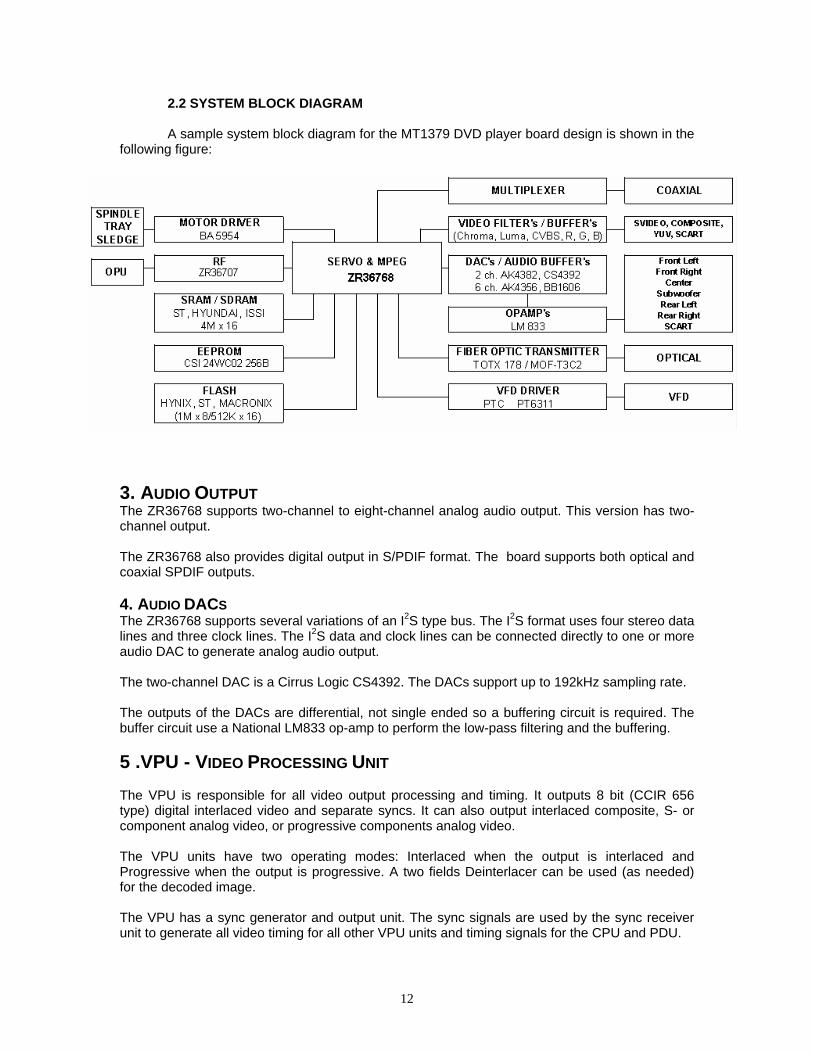
2.2 SYSTEM BLOCK DIAGRAM A sample system block diagram for the MT1379 DVD player board design is shown in the
following figure:
3. AUDIO OUTPUT The ZR36768 supports two-channel to eight-channel analog audio output. This version has two-channel output. The ZR36768 also provides digital output in S/PDIF format. The board supports both optical and coaxial SPDIF outputs. 4. AUDIO DACS The ZR36768 supports several variations of an I2S type bus. The I2S format uses four stereo data lines and three clock lines. The I2S data and clock lines can be connected directly to one or more audio DAC to generate analog audio output. The two-channel DAC is a Cirrus Logic CS4392. The DACs support up to 192kHz sampling rate. The outputs of the DACs are differential, not single ended so a buffering circuit is required. The buffer circuit use a National LM833 op-amp to perform the low-pass filtering and the buffering. 5 .VPU - VIDEO PROCESSING UNIT The VPU is responsible for all video output processing and timing. It outputs 8 bit (CCIR 656 type) digital interlaced video and separate syncs. It can also output interlaced composite, S- or component analog video, or progressive components analog video. The VPU units have two operating modes: Interlaced when the output is interlaced and Progressive when the output is progressive. A two fields Deinterlacer can be used (as needed) for the decoded image. The VPU has a sync generator and output unit. The sync signals are used by the sync receiver unit to generate all video timing for all other VPU units and timing signals for the CPU and PDU.
12

The image post-processing unit can scale the stored image (horizontally and vertically with scale ratios of 1/2 to 2) and shift it with 1/4 pixel resolution. Then, it can enhance the image and pad it with background colour. In addition, the VPU has a DVD sub-picture decoding unit. The sub-picture is blended with the enhanced image. The resulting image is blended with an OSD image generated by a 2, 4 or 8 bits per pixel OSD Decoder. Finally, closed captions is added to generate the final digital video. The final interlaced digital video is processed by the video encoder to generate six 10 bit video streams. One stream is composite video, the next two are the luma and composite chroma components of the Svideo format. The three other streams are color components, either Y,U,V or R,G,B. Four of the sixstreams are converted to analog by four on-chip 54 MHz DACs. For three of the four DACs, the selected combination can be: (a) Interlaced composite and S-video; (b) Three interlaced components (either Y,U,V or R,G,B); (c) Three progressive Y,U,V components. For cases (a) and (b), the fourth DAC can output either the composite signal, the luma (Y) signal, or the chroma (C) signal of the S-Video. The final progressive digital video is processed by the video encoder to generate three 10 bit video color components streams, either Y,U,V or R,G,B. The streams are converted to analog by three on-chip 54 MHz DACs. The fourth DAC has no output. 6. FLASH MEMORY The decoder board supports 70ns Flash memories. The CPU executes from a NOR type Flash memory with 16 bit data bus. Alternately, a compatible EPROM, PROM, OTPROM or masked ROM can be connected. 7. SERIAL EEPROM MEMORY
An I2C serial EEPROM is used to store user configuration (i.e. language preferences, speaker setup, etc.) and software configuration.. Industry standard EEPROM range in size from 1kbit to 256kbit and share the same IC footprint and pinout. The default device is 2kbit, 256kx 8, SOIC8 CSI 24WC02 or equivalent.
8. ADP - AUDIO DATA PROCESSOR The ADP is the audio processing unit of the I64. It is based on a 20 bits data and 32 bits instruction ADP44 core. The ADP core has attached to it 24 KWords (32 bits) instruction and data ROM, 5 Kwords (32 bits) instruction RAM, 8 KWords (20 bits) data RAM, 1 KWords (20 bits) data DMA caches, and several peripheral units mentioned below. The peripherals are DMA interface unit, audio code interface unit, CPU and DVP interface unit, realtime clock unit, serial port unit, serial port PLL unit and interrupt handler. All the ADP peripheral units are connected to the ADP core through the AP_Bus (audio peripherals bus). The interrupt handler is also connected directly to the interrupt port of the ADP core. Several external pins (multiplexed with the digital video pins) can be used for debugging. This interface is usually called "ICE" (which is of course a mis-nomer as ICE means "In-Circuit Emulation") but they are similar to JTAG.
13

9. PLL - PROCESSING CLOCK GENERATION UNIT The PLL unit consists of three sub-units: The PLLa unit generates (under ADP control) the audio interface master clock (AMCLK). It has 13 bits of frequency multiply and divide factors. Its input can be a separate clock generator or be (externally) tied to the clock generator or crystal input to the processing clock PLL (see below). An external control pin can indicate by-pass of this PLL unit to be used mainly for testing or for low jitter operation. The PLLp unit generates (under CPU control) the processing clocks. It has 8 bits of frequency multiply and 6 bits of divide ratios. In most cases the input clock frequency will be 27 MHz multiplied by 5 and divided by 1 to generate clk and PCLK with frequency of 135 MHz. An external control pin can indicate by-pass of this PLL unit to be used mainly for testing. The PLL also generates the 27 MHz video clock signal (clk27 and VCLKx2), the encoder and DACs 54 MHz processing signal (clk54), the RF channel ADC sampling clock (rf_clk) and the servo ADC and DACs sampling clock (adc_servo_clk). The third unit is responsible to generate the internal reset signals to all I64 units after detecting a proper power-up condition or a proper external reset input signal. 10. FRONT PANEL 10.1 VFD CONTROLLER
The VFD controller is a PTC PT6311. This controller is not a processor, but does include a simple state machine, which scans the VFD and reads the front panel button matrix. The 6311 also includes RAM so it can store the current state of all the VFD icons and segments. Therefore, the 6311 needs only be accessed when the VFD status changes and when the button status is read. The ZR36768 can control this chip directly using PIO pins or can allow the front panel PIC to control the VFD. 11. CONNECTORS 11.1 SCART CONNECTORS Pinout of the scart connector: 1 Audio Right Out 2 Audio Right In 3 Audio Left / Monu Out 4 Audio Gnd 5 Blue Gnd 6 Audio Left / Mono In 7 Blue 8 Control Voltage 9 Green Gnd 10 Comms Data 2 11 Green 12 Comms Data 1
14
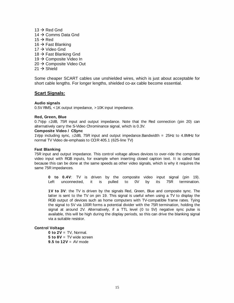
13 Red Gnd 14 Comms Data Gnd 15 Red 16 Fast Blanking 17 Video Gnd 18 Fast Blanking Gnd 19 Composite Video In 20 Composite Video Out 21 Shield Some cheaper SCART cables use unshielded wires, which is just about acceptable for short cable lengths. For longer lengths, shielded co-ax cable become essential. Scart Signals: Audio signals0.5V RMS, <1K output impedance, >10K input impedance. Red, Green, Blue0.7Vpp ±2dB, 75R input and output impedance. Note that the Red connection (pin 20) can alternatively carry the S-Video Chrominance signal, which is 0.3V. Composite Video / CSync1Vpp including sync, ±2dB, 75R input and output impedance.Bandwidth = 25Hz to 4.8MHz for normal TV Video de-emphasis to CCIR 405.1 (625-line TV) Fast Blanking75R input and output impedance. This control voltage allows devices to over-ride the composite video input with RGB inputs, for example when inserting closed caption text. It is called fast because this can be done at the same speeds as other video signals, which is why it requires the same 75R impedances.
0 to 0.4V: TV is driven by the composite video input signal (pin 19). Left unconnected, it is pulled to 0V by its 75R termination. 1V to 3V: the TV is driven by the signals Red, Green, Blue and composite sync. The latter is sent to the TV on pin 19. This signal is useful when using a TV to display the RGB output of devices such as home computers with TV-compatible frame rates. Tying the signal to 5V via 100R forms a potential divider with the 75R termination, holding the signal at around 2V. Alternatively, if a TTL level (0 to 5V) negative sync pulse is available, this will be high during the display periods, so this can drive the blanking signal via a suitable resistor.
Control Voltage0 to 2V = TV, Normal. 5 to 8V = TV wide screen 9.5 to 12V = AV mode
15

12. CIRCUIT DESCRIPTION 12.1 POWER SUPPLY: • Socket PL2 is the 220VAC input. • 2.5A fuse F1 is used to protect the device against short circuit. • Line filters and capacitors L1, C1, L5 and L6 are used to block the parasitic
coming from the mains. They also prevent the noise, produced in the circuit, from being injected to the line.
• Voltage is rectified by using diodes D1, D2, D3 and D4. Using capacitor C3 (470μf) a DC voltage is produced. (310- 320VDC).
• The current in the primary side of the transformer TR1 comes to the SMPS IC (IC1 STR-A6351). The SMPS IC has a eight-pin DIP case.
• Voltages on the secondary side are as follows: -22V, -12V, 3.3V, 5V, 15V. • IC3 TL431 is a constant current regulator. TL431 watches the 5 volts and
supplies the required current to IC2. There are a LED and a photo transistor in IC2. The LED inside the IC2 transmits the value of the current from IC3 to phototransistor. Depending on the current gain of the phototransistor IC1 keeps the voltage on the 5-volt-winding constant.
• –22 Volts is used to feed the VFD (Vacuum Fluorescent Display) driver IC on the front panel.
12.2 FRONT PANEL: • All the functions on the front panel are controlled by IC1 (ZR36768) on the
mainboard. • IC1 sends the commands to IC2 PT6311 via socket PL1 (pins 3,4 and 5). • There are 16 keys scanning function, 2 LED outputs, 1 Stand-by output and
VFD drivers on IC2. • Pin 52 is the oscillator pin and is connected via R5 56K. • LED D6 is red in stand-by mode and green when the device is on. When
entering stand-by mode, pin 48 goes HIGH (+5V) and controls the transistor Q2 on the power board.
• Vacuum fluorescent display MD2 is specially designed for DVD. • The scanned keys are transmitted via IC2 pin 5 and 6 to IC1 on the
mainboard. • IR remote control receiver module IC3 (TSOP1836) sends the commands
from the remote control directly to U1. • Socket PL2 carries the VFD filament voltage and –22 Volts. 12.3 BACK PANEL: • There are 1 SCART connector (PL2), 2 pieces RCA audio jacks, for audio
output, 1 coaxial digital audio output JK1 and 1 laser digital audio output MD1 on the back panel.
16

• TOTX176 is used for laser output. • For coaxial audio output SPDIF is used. • Q4, Q5, Q6, Q7, Q8 and Q9 transistors are to mute the audio outputs while
switching the state of the unit(power on/off) • There are two op-amps in U9, U12 and U14. They are used for left,right,rear
left and right, subwoofer center audio channels. The feedback resistor is amplifying the gain.
• SCART pin 8 controls 16:9 and 4:3 mode using Q19, Q20, Q21 and Q22. • When the pin8 output of the scart becomes 5 Volts, 4:3 mode is selected and
16:9 mode is selected when this output becomes 0. The circuit is adjusted to output 12 Volts for 4:3 mode and 6 Volts for 16:9 mode.
• Transistors Q19, Q20, Q21 and Q22 transmit these voltages when the device is turned on and cuts them off when it is turned off.
• FBL on pin 16 transmits 5 Volts via transistors Q17 and Q18 when the device is on.
• Socket PL2, which is coming from the mainboard, transmits RED, GREEN, BLUE and VIDEO signals to SCART over the buffer stage.
• LUMA and CHROMA signals of S-Video are transmitted to S-Video socket via transistors Q25 - Q29, Q26 - Q30 respectively.
13.SOFWARE UPTATE 13.1 Universal Service Password for Parental Level = 1369 13.2 Version Page (Hidden Menu)
To see Version Page; - Press DISPLAY button from remote
- Press “1”-“3”-“5”-“7” at Setup Menu - Setup Menu screen refresh and “Version” selection can be seen under
“Preferences Setup” - Select “Version” for Version Page - First 6 lines contains current VERSION information.1st and 5th line is for
customers Other lines (Sub-Ver, 8032, Servo, Risc) for factory use only; 1st line contains build information example: 02.01.EF65 5th line contains hardware option example: A6AO1.bin 7th line contains Region Code (Management )
- Press “DISPLAY” button on remote control to exit hidden menu. 5th line also shows CD update file name. It defines also Hardware options.
17

13.3 Build Names for Hardware Options DVD6000 MTK Concept has 3 different hardware option: 1. 2 OPU Option 2. 3 VFD Option +TV DVD 3. 4 DAC Option 4. 3 Language Group (19 Language total) There is a naming standard for software builds according to player’s hardware options like; X X X X X. bin VFD OPU DAC VFD Type: O = Old VFD / N = New small VFD / T = TV DVD/7 NoVFD OPU Type: A = ASA SANYO HD60 / F = FUSS HITACHI HOP 1200 DAC Type: A6 = AK4356 / A2 = AK4382 / P6 = PCM1606 / C2 = CS4392 Example: A6AO1.bin = AK4356, ASA, OLD VFD,Language Group 1 C2FN2.bin = CS4392 ,ASA, NEW small VFD, Language Group 2 Note: Update CD should have no volume ID. 13.4 CD UPTADE PROCEDURE:
1) Any Player can be updated automatically with Update CD which contains proper files (see Service Cd.Jpg ) 2) Burn up CD within proper files 2) There should be no Volume Name for CD 3) Open Tray and place update CD 4) You can see "Upgrade File Detected. Press Play to start" OSD message 5) Press Play button to start upgrade 6) You can see "File copying" OSD message for a few second 7) Tray is open automatically 8) No need for CD in tray;Take it from tray. 9) During upgrade procedure "CD upgrade start, Please wait.." indicator at OSD, and "UPG" indicator at VFD 10) Upgrade procedure takes about a few minutes, please wait if tray is open.
18

11) When CD update is finished tray is closed, screen is refreshed, update is finished. 12) To see Version Page; - Press DISPLAY button from remote
- Press “1”-“3”-“5”-“7” at Setup Menu - Setup Menu screen refresh and “Version” selection can be seen under “Preferences Setup”
- Select “Version”or version Page - 1st line contains release number like EFXX - 5th line contains hardware options and build number
- Press “DISPLAY” button on remote control to exit hidden menu. 13.5 Region Management At version Page by using arrow keys you can change region. 14.CIRCUIT SCHEMATICS : Appendix A
19