Embed Size (px)
Citation preview
catalog
VF and VL Fan-Coil Units Floor-Mounted, Vertical
2 ENVIRO-TEC
Catalog: ET115.26-EG9 (1115) VF & VL Fan-Coil Units Floor-Mounted, Vertical
Features and Benefits . . . . . . . . . . . . . . . . . . . . . . . . . . . . . . . . . . . . . . . . . . . . . . . . . . . . . . . . . . . . . . . . . . . . . . . 3Construction Features . . . . . . . . . . . . . . . . . . . . . . . . . . . . . . . . . . . . . . . . . . . . . . . . . . . . . . . . . . . . . . . . . . . . . . . 4Standard and Optional Features . . . . . . . . . . . . . . . . . . . . . . . . . . . . . . . . . . . . . . . . . . . . . . . . . . . . . . . . . . . . . . . 9Coil Data . . . . . . . . . . . . . . . . . . . . . . . . . . . . . . . . . . . . . . . . . . . . . . . . . . . . . . . . . . . . . . . . . . . . . . . . . . . . . . . . . 11Physical Data . . . . . . . . . . . . . . . . . . . . . . . . . . . . . . . . . . . . . . . . . . . . . . . . . . . . . . . . . . . . . . . . . . . . . . . . . . . . . 13Electric Heat . . . . . . . . . . . . . . . . . . . . . . . . . . . . . . . . . . . . . . . . . . . . . . . . . . . . . . . . . . . . . . . . . . . . . . . . . . . . . . 15Fan Performance . . . . . . . . . . . . . . . . . . . . . . . . . . . . . . . . . . . . . . . . . . . . . . . . . . . . . . . . . . . . . . . . . . . . . . . . . . 16Motor and Fan Data . . . . . . . . . . . . . . . . . . . . . . . . . . . . . . . . . . . . . . . . . . . . . . . . . . . . . . . . . . . . . . . . . . . . . . . . 25Sound Data . . . . . . . . . . . . . . . . . . . . . . . . . . . . . . . . . . . . . . . . . . . . . . . . . . . . . . . . . . . . . . . . . . . . . . . . . . . . . . 27Dimensional Data . . . . . . . . . . . . . . . . . . . . . . . . . . . . . . . . . . . . . . . . . . . . . . . . . . . . . . . . . . . . . . . . . . . . . . . . . . 28Piping Packages . . . . . . . . . . . . . . . . . . . . . . . . . . . . . . . . . . . . . . . . . . . . . . . . . . . . . . . . . . . . . . . . . . . . . . . . . . . 36Guide Specifications . . . . . . . . . . . . . . . . . . . . . . . . . . . . . . . . . . . . . . . . . . . . . . . . . . . . . . . . . . . . . . . . . . . . . . . . 44
TABLE OF CONTENTS
NOTES:• Aweb-basedComputerSelectionProgram,“Web-Select”,isavailabletofacilitatetheselectionprocess. Contactyourrepresentativetoobtainaccesstothispowerfulandtime-savingprogram.• Somedrawingsarenotshowninthiscatalog.• Alldatahereinissubjecttochangewithoutnotice.• Drawingsnotforinstallationpurposes.• ETLReportNumber3096645CRT-002.
ENVIRO-TEC 3
VF & VL Fan-Coil Units Floor-Mounted, Vertical Catalog: ET115.26-EG9 (1115)
FEATURES AND BENEFITS
DESIGN FLEXIBILITY
TheENVIRO-TECverticalfloormountedfancoilunitsare designed to maximize flexibility of selection andinstallation .
The units are also designed to exceed the stringent quality standards of the institutional market, whileremainingcostcompetitiveinthelightcommercialseg-ment of the market .
ENVIRO-TECvertical fancoilunitsset thenewstan-dardsforquality,flexibility,andcompetitivepricing.
DESIGN FLEXIBILITY
Theextensivevarietyofstandardoptionsavailableonverticalfloorfancoilunitsarewhereyoufindthever-satility to fit any HVAC system designer’s needs.ModelsVFEandVFSallow foradditionalheightandwidthdimensionstomeetarchitecturaldemand.
Options include:singlewallstainlesssteeldrainpan;MERV7,MERV8andMERV13 filters; andelectricheatwithsinglepointpowerconnection.AllelectricheatunitsarelistedwithETLasanassemblyandcarrythecETLlabel.
AllunitscomplywiththelatesteditionofAHRIStandard440 for testingand rating fancoilunits,arecertified,anddisplaytheAHRIsymbol.
High efficiency motors, fan relays, disconnects andfusingmeaneasiercoordinationbetweenmechanicaland electrical trades .
CoiloptionsallowforthreeorfourrowchilledwaterorDXcoolingcoils,andoneortworowhotwaterorsteamheating coils .
Silentsolidstaterelaysareavailableforfanandelectricheatcontrolinsoundsensitiveenvironments.
CONVENIENT INSTALLATION
All vertical floor fan coils are shipped completelyassembled, reducing field installation timeand labor.Allunitsare thoroughly inspectedand testedprior toshipment, eliminating potential problems at startup.Motorwiringisbroughttoajunctionboxontheinsideof the unit end pocket, reducing electrical hook-uptime .
Factory furnished valve packages assure proper fit,operation and performance .
Forfasttrackjobs,theverticalfloorfancoilisavailableonQuickShipwith5,10or15dayleadtimes.
OPTIMUM BUILDING PERFORMANCE
Concealedverticalfloorfancoilchassisarebuiltfromgalvanizedsteel.Exposedcabinetmodelsarepowdercoatedgalvannealedsteel.
Allunits,withorwithoutelectricheat,arecETLlistedand labeled. All wiring is in compliance with NEC, assuringsafetyandqualityfortheowner.
Floormounted cabinetmodels feature finned tubularheatingelementsinthereheatposition,protectingroomoccupants from electrical shock .
Verticalfloorfancoilunitshavearemovablefan/drainpanassembly.Theentirefanassemblycanbeeasilyremovedfromtheunitandservicedonaworkbench.
Filters are easily replaceable from the return air toespacewithouttheneedfortoolsorremovalofthefrontpanel (VF only) .
4 ENVIRO-TEC
Catalog: ET115.26-EG9 (1115) VF & VL Fan-Coil Units Floor-Mounted, Vertical
CONSTRUCTION FEATURES
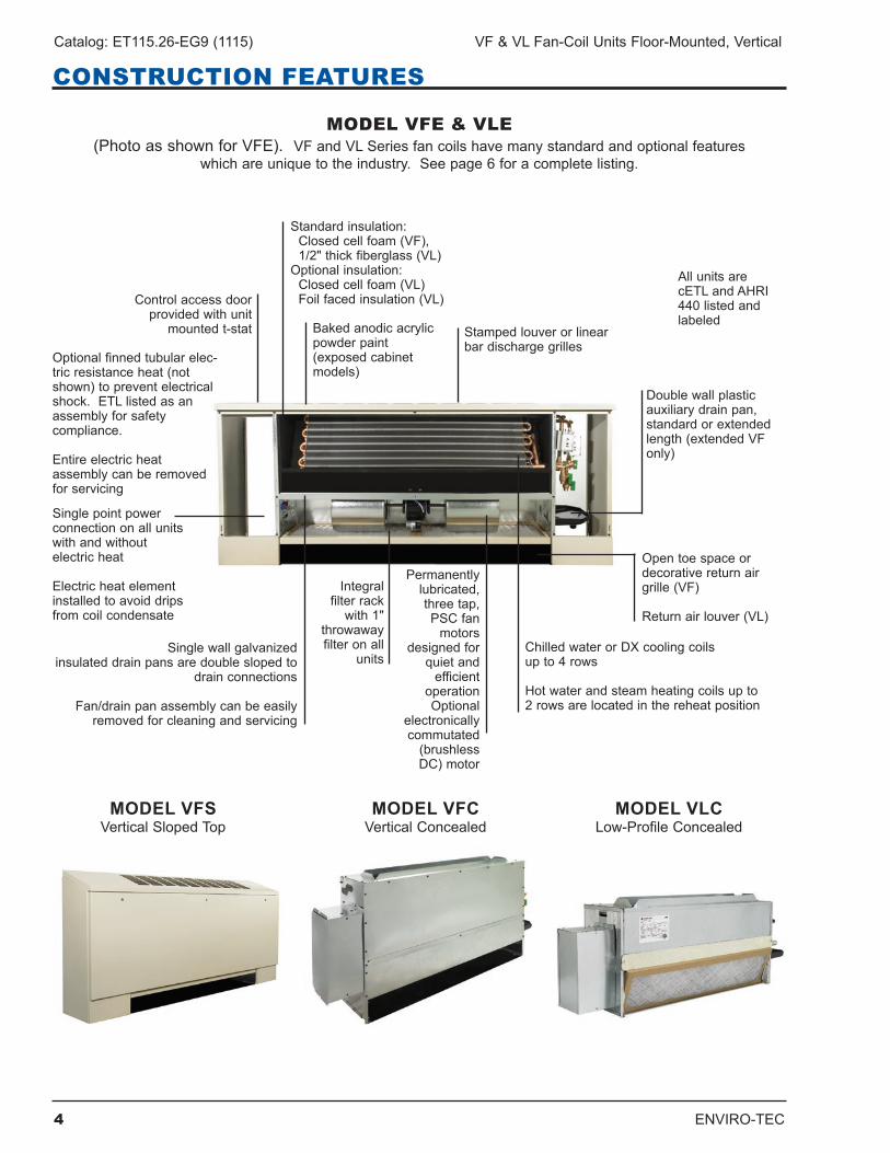
MODEL VFE & VLE(PhotoasshownforVFE). VFandVLSeriesfancoilshavemanystandardandoptionalfeatures
whichareuniquetotheindustry.Seepage6foracompletelisting.
MODEL VFSVertical Sloped Top
MODEL VFCVertical Concealed
AllunitsarecETLandAHRI440listedandlabeled
Singlewallgalvanizedinsulateddrainpansaredoubleslopedto
drain connections
Fan/drainpanassemblycanbeeasilyremovedforcleaningandservicing
ChilledwaterorDXcoolingcoilsupto4rows
Hotwaterandsteamheatingcoilsupto2rowsarelocatedinthereheatposition
Open toe space or decorativereturnairgrille (VF)
Returnairlouver(VL)
Optionalfinnedtubularelec-tric resistance heat (not shown)topreventelectricalshock.ETLlistedasanassemblyforsafety compliance .
Entire electric heat assemblycanberemovedforservicing
Baked anodic acrylic powderpaint(exposedcabinetmodels)
Standard insulation:Closedcellfoam(VF),1/2"thickfiberglass(VL)Optional insulation:Closedcellfoam(VL)Foilfacedinsulation(VL)
Integral filter rack with1"
throwawayfilter on all
units
Singlepointpower connection on all units withandwithout electric heat
Electric heat element installedtoavoiddripsfrom coil condensate
Control access door providedwithunit
mounted t-stat Stampedlouverorlinearbardischargegrilles
Doublewallplastic auxiliarydrainpan,standard or extended length (extended VF only)
MODEL VLCLow-ProfileConcealed
Permanently lubricated,threetap,PSC fan
motors designed for
quiet and efficient
operationOptional
electronically commutated (brushlessDC) motor
ENVIRO-TEC 5
VF & VL Fan-Coil Units Floor-Mounted, Vertical Catalog: ET115.26-EG9 (1115)
CONSTRUCTION FEATURES
MODELS VFE/VFS/VFC
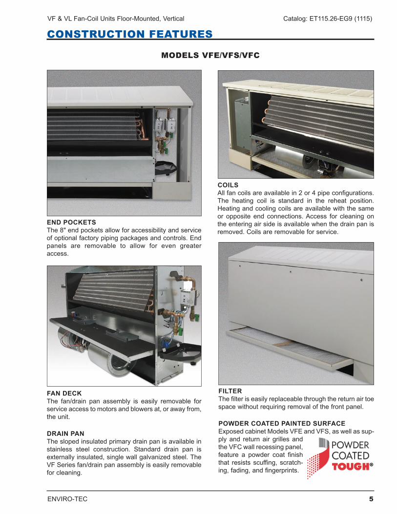
END POCKETSThe8"endpocketsallowforaccessibilityandserviceof optional factory piping packages and controls . End panels are removable to allow for even greateraccess .
FAN DECKThe fan/drain pan assembly is easily removable forserviceaccesstomotorsandblowersat,orawayfrom,the unit .
DRAIN PANTheslopedinsulatedprimarydrainpanisavailableinstainless steel construction . Standard drain pan is externallyinsulated,singlewallgalvanizedsteel.TheVFSeriesfan/drainpanassemblyiseasilyremovablefor cleaning .
COILSAllfancoilsareavailablein2or4pipeconfigurations.The heating coil is standard in the reheat position . Heatingandcoolingcoilsareavailablewiththesameor opposite end connections.Access for cleaning ontheenteringairsideisavailablewhenthedrainpanisremoved.Coilsareremovableforservice.
FILTERThefilteriseasilyreplaceablethroughthereturnairtoespacewithoutrequiringremovalofthefrontpanel.
POWDER COATED PAINTED SURFACEExposedcabinetModelsVFEandVFS,aswellassup-ply and return air grilles and theVFCwallrecessingpanel,feature a powder coat finishthat resistsscuffing, scratch-ing,fading,andfingerprints.
6 ENVIRO-TEC
Catalog: ET115.26-EG9 (1115) VF & VL Fan-Coil Units Floor-Mounted, Vertical
CONSTRUCTION FEATURES
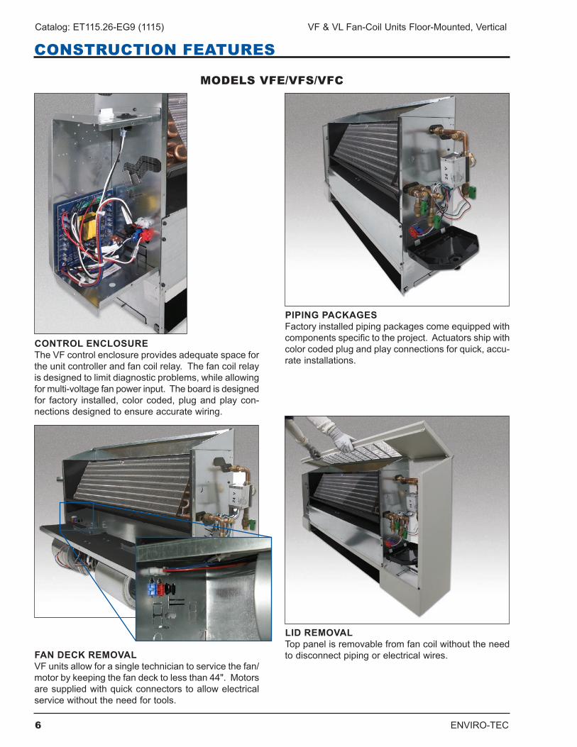
CONTROL ENCLOSURETheVFcontrolenclosureprovidesadequatespaceforthe unit controller and fan coil relay . The fan coil relay isdesignedtolimitdiagnosticproblems,whileallowingformulti-voltagefanpowerinput.Theboardisdesignedfor factory installed,colorcoded,plugandplaycon-nectionsdesignedtoensureaccuratewiring.
FAN DECK REMOVALVFunitsallowforasingletechniciantoservicethefan/motorbykeepingthefandecktolessthan44".Motorsaresuppliedwithquickconnectorstoallowelectricalservicewithouttheneedfortools.
PIPING PACKAGESFactoryinstalledpipingpackagescomeequippedwithcomponentsspecifictotheproject.Actuatorsshipwithcolorcodedplugandplayconnectionsforquick,accu-rate installations .
LID REMOVALToppanelisremovablefromfancoilwithouttheneedtodisconnectpipingorelectricalwires.
MODELS VFE/VFS/VFC
ENVIRO-TEC 7
VF & VL Fan-Coil Units Floor-Mounted, Vertical Catalog: ET115.26-EG9 (1115)
MODELS VLE/VLC
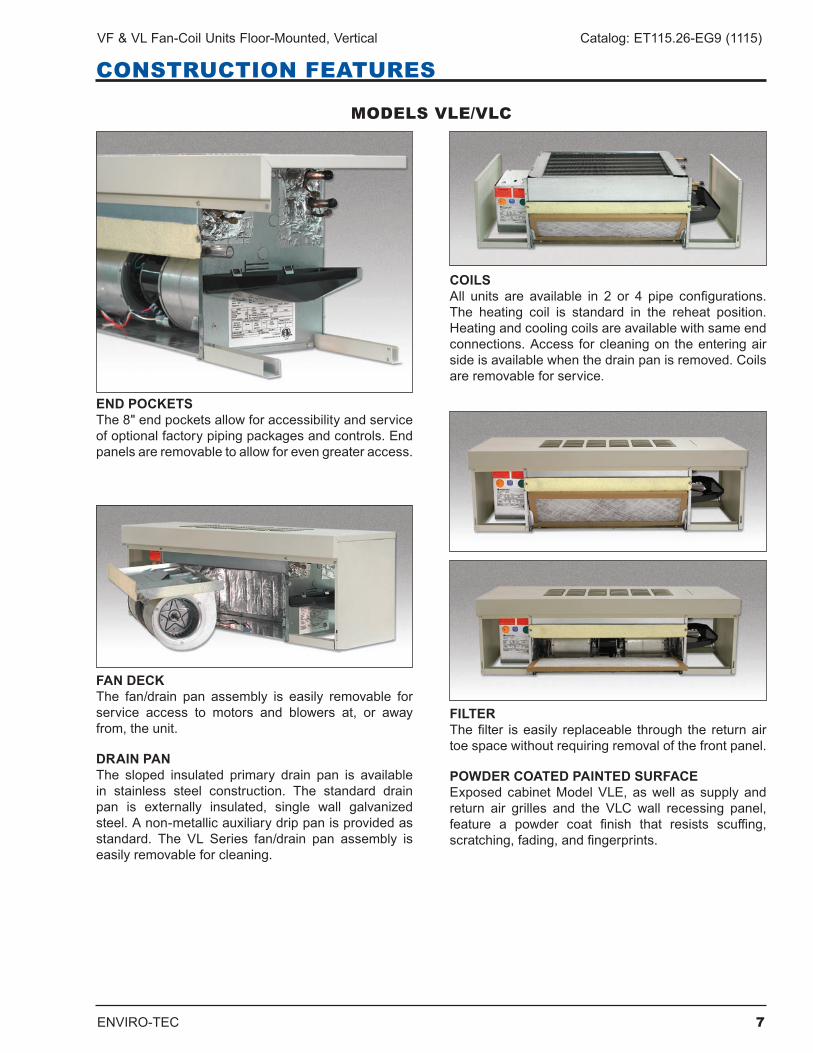
END POCKETSThe8"endpocketsallowforaccessibilityandserviceof optional factory piping packages and controls . End panelsareremovabletoallowforevengreateraccess.
FAN DECKThe fan/drain pan assembly is easily removable forservice access to motors and blowers at, or awayfrom,theunit.
DRAIN PANThe sloped insulated primary drain pan is availablein stainless steel construction . The standard drain pan is externally insulated, single wall galvanizedsteel.Anon-metallicauxiliarydrippanisprovidedasstandard. The VL Series fan/drain pan assembly iseasilyremovableforcleaning.
COILSAll units are available in 2 or 4 pipe configurations.The heating coil is standard in the reheat position . Heatingandcoolingcoilsareavailablewithsameendconnections.Access forcleaningon theenteringairsideisavailablewhenthedrainpanisremoved.Coilsareremovableforservice.
FILTERThefilter iseasily replaceable through the returnairtoespacewithoutrequiringremovalofthefrontpanel.
POWDER COATED PAINTED SURFACEExposedcabinetModelVLE,aswell as supplyandreturn air grilles and the VLC wall recessing panel,feature a powder coat finish that resists scuffing,scratching,fading,andfingerprints.
CONSTRUCTION FEATURES
8 ENVIRO-TEC
Catalog: ET115.26-EG9 (1115) VF & VL Fan-Coil Units Floor-Mounted, Vertical
CONSTRUCTION FEATURES
MODELS VLE/VLC
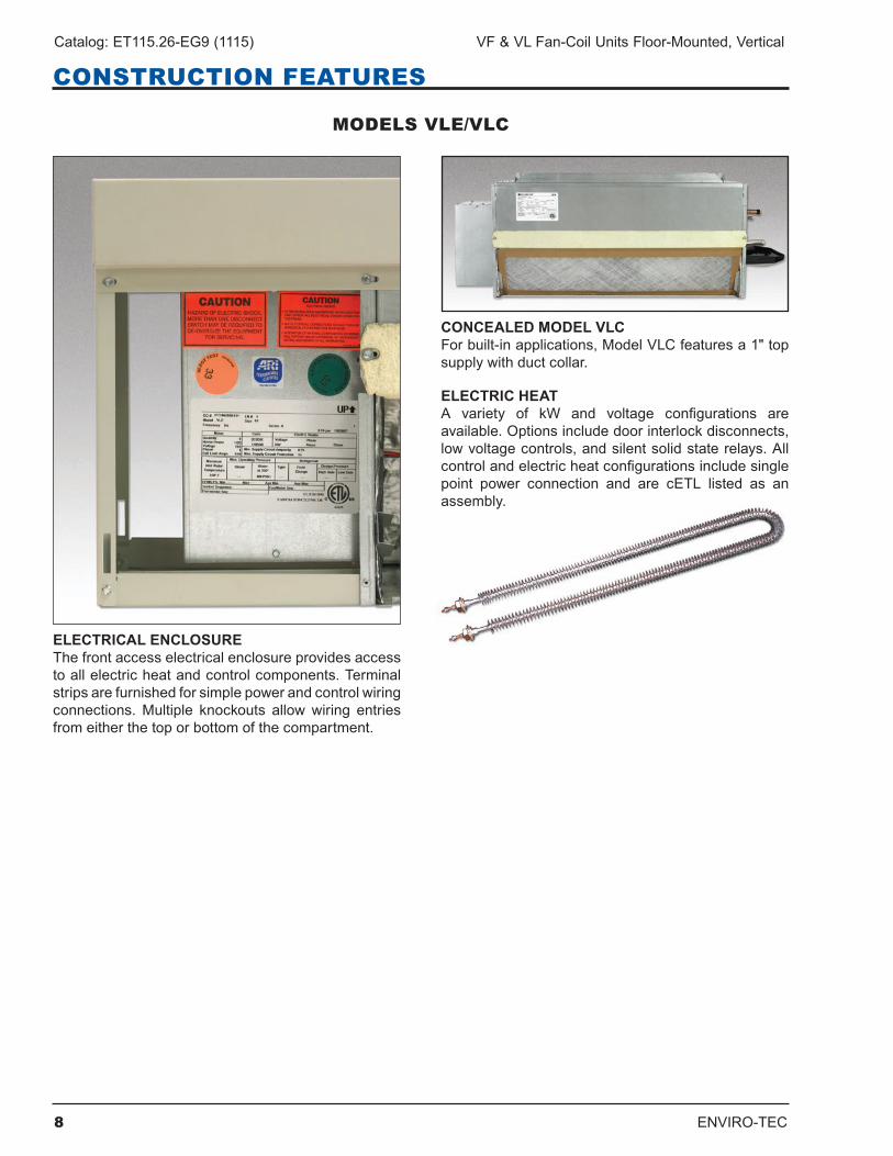
CONCEALED MODEL VLCForbuilt-inapplications,ModelVLCfeaturesa1"topsupplywithductcollar.
ELECTRIC HEATA variety of kW and voltage configurations areavailable.Optionsincludedoorinterlockdisconnects,lowvoltagecontrols,andsilentsolidstaterelays.Allcontrolandelectricheatconfigurationsincludesingle point power connection and are cETL listed as anassembly.
ELECTRICAL ENCLOSUREThefrontaccesselectricalenclosureprovidesaccessto all electric heat and control components . Terminal stripsarefurnishedforsimplepowerandcontrolwiringconnections.Multiple knockouts allowwiring entriesfromeitherthetoporbottomofthecompartment.
ENVIRO-TEC 9
VF & VL Fan-Coil Units Floor-Mounted, Vertical Catalog: ET115.26-EG9 (1115)
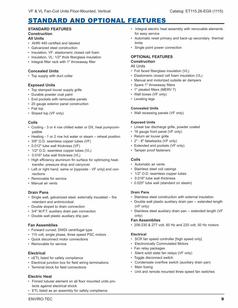
STANDARD AND OPTIONAL FEATURESSTANDARD FEATURESConstructionAll Units• AHRI440certifiedandlabeled•Galvanizedsteelconstruction•Insulation,VF:elastomericclosedcellfoam•Insulation,VL:1/2"thickfiberglassinsulation•Integralfilterrackwith1"throwawayfilter
Concealed Units•Topsupplywithductcollar
Exposed Units•Topstampedlouversupplygrille•Durablepowdercoatpaint•Endpocketswithremovablepanels•20gaugeexteriorpanelconstruction•Flattop•Slopedtop(VFonly)
Coils•Cooling-3or4rowchilledwaterorDX,heatpumpcom-patible
•Heating-1or2rowhotwaterorsteam–reheatposition•3/8"O.D.seamlesscoppertubes(VF)•0.012"tubewallthickness(VF)• 1/2"O.D.seamlesscoppertubes(VL)• 0.016"tubewallthickness(VL)•Highefficiencyaluminumfinsurfaceforoptimizingheat-transfer,pressuredropandcarryover
•Leftorrighthand,sameor[opposite-VFonly]endcon-nections
•Removableforservice•Manualairvents
Drain Pans•Singlewall,galvanizedsteel,externallyinsulated–fireretardantandantimicrobial
•Doubleslopedtodrainconnection•3/4"M.P.T.auxiliarydrainpanconnection•Doublewallplasticauxiliarydrippan
Fan Assemblies•Forwardcurved,DWDIcentrifugaltype•115volt,singlephase,threespeedPSCmotors•Quickdisconnectmotorconnections•Removableforservice
Electrical•cETLlistedforsafetycompliance•Electricaljunctionboxforfieldwiringterminations•Terminalblockforfieldconnections
Electric Heat•Finnedtubularelementonallfloormountedunitspro-
tects against electrical shock•ETLlistedasanassemblyforsafetycompliance
•Integralelectricheatassemblywithremovableelementsforeasyservice
•Automaticresetprimaryandback-upsecondarythermallimits
•Singlepointpowerconnection
OPTIONAL FEATURESConstructionAllUnits•Foilfacedfiberglassinsulation(VL)•Elastomericclosedcellfoaminsulation(VL)•Manualandmotorizedoutsideairdampers•Spare1"throwawayfilters•1"pleatedfilters(MERV7)•Wallboxes(VFonly)•Levelinglegs
Concealed Units•Wallrecessingpanels(VFonly)
Exposed Units•Linearbardischargegrille,powdercoated•16gaugefrontpanel(VFonly)•Returnairlouvergrille•2"-8"falsebacks(VFonly)•Extendedendpockets(VFonly)•Tamperprooffasteners
Coils• Automaticairvents•Stainlesssteelcoilcasings• 1/2"O.D.seamlesscoppertubes• 0.016"tubewallthickness•0.025"tubewall(standardonsteam)
Drain Pans•Stainlesssteelconstructionwithexternalinsulation•Doublewallplasticauxiliarydrainpan--extendedlength
(VF only)•Stainlesssteelauxiliarydrainpan--extendedlength(VF
only)Fan Assemblies•208-230&277volt,60Hzand220volt,50Hzmotors
Electrical•SCRfanspeedcontroller[highspeedonly]• ElectronicallyCommutatedMotors•Fanrelaypackages•Silentsolidstatefanrelays(VFonly)•Toggledisconnectswitch•Condensateoverflowswitch(auxiliarydrainpan)•Mainfusing•Unitandremotemountedthreespeedfanswitches
10 ENVIRO-TEC
Catalog: ET115.26-EG9 (1115) VF & VL Fan-Coil Units Floor-Mounted, Vertical
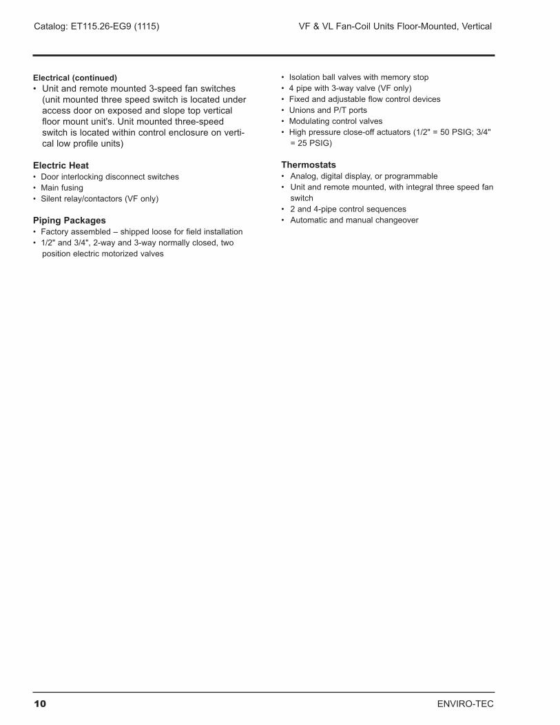
Electrical (continued)• Unitandremotemounted3-speedfanswitches(unitmountedthreespeedswitchislocatedunderaccessdooronexposedandslopetopverticalfloormountunit's.Unitmountedthree-speedswitchislocatedwithincontrolenclosureonverti-callowprofileunits)
Electric Heat•Doorinterlockingdisconnectswitches•Mainfusing•Silentrelay/contactors(VFonly)
Piping Packages•Factoryassembled–shippedlooseforfieldinstallation•1/2"and3/4",2-wayand3-waynormallyclosed,twopositionelectricmotorizedvalves
•Isolationballvalveswithmemorystop•4pipewith3-wayvalve(VFonly)•Fixedandadjustableflowcontroldevices•UnionsandP/Tports•Modulatingcontrolvalves•Highpressureclose-offactuators(1/2"=50PSIG;3/4"=25PSIG)
Thermostats•Analog,digitaldisplay,orprogrammable•Unitandremotemounted,withintegralthreespeedfanswitch
• 2and4-pipecontrolsequences• Automaticandmanualchangeover
ENVIRO-TEC 11
VF & VL Fan-Coil Units Floor-Mounted, Vertical Catalog: ET115.26-EG9 (1115)
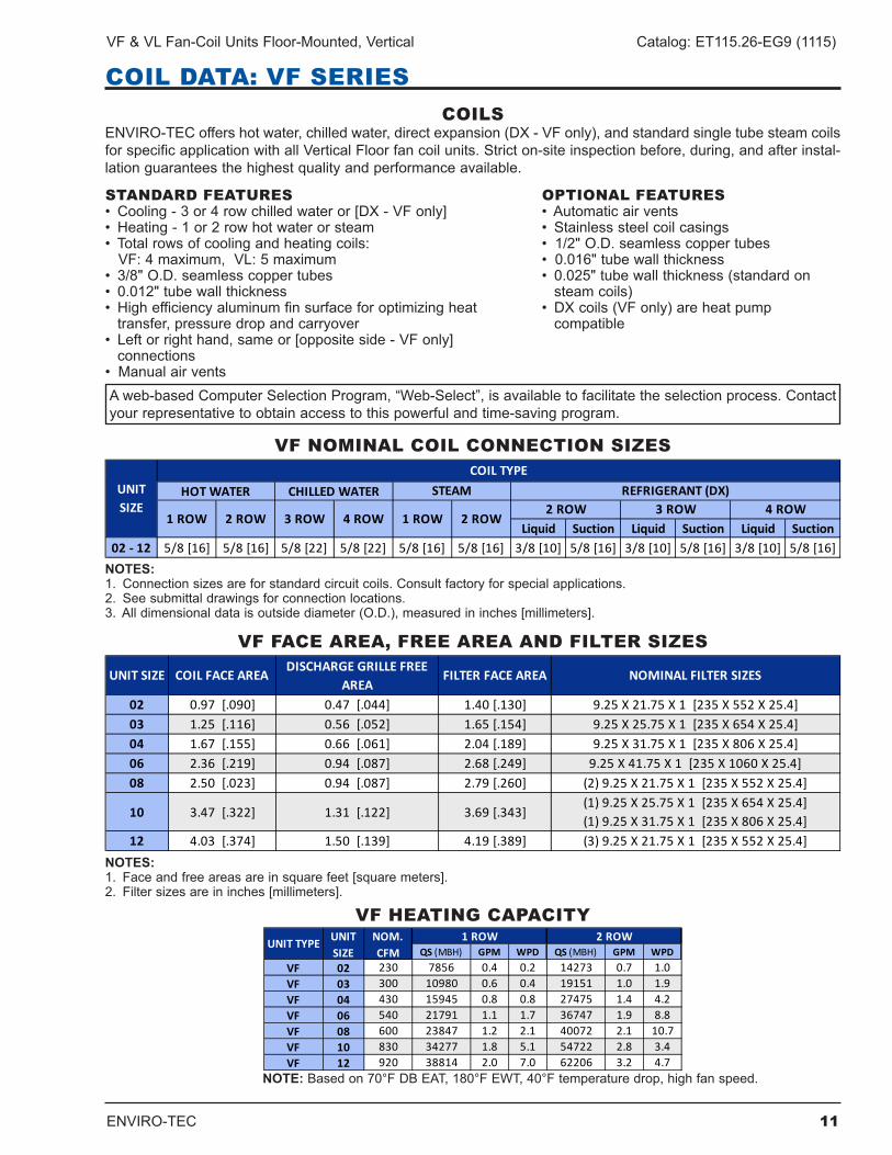
COIL DATA: VF SERIESCOILS
ENVIRO-TECoffershotwater,chilledwater,directexpansion(DX-VFonly),andstandardsingletubesteamcoilsforspecificapplicationwithallVerticalFloorfancoilunits.Stricton-siteinspectionbefore,during,andafterinstal-lationguaranteesthehighestqualityandperformanceavailable.
STANDARD FEATURES• Cooling-3or4rowchilledwateror[DX-VFonly]• Heating-1or2rowhotwaterorsteam• Totalrowsofcoolingandheatingcoils: VF:4maximum,VL:5maximum• 3/8"O.D.seamlesscoppertubes• 0.012"tubewallthickness• Highefficiencyaluminumfinsurfaceforoptimizingheattransfer,pressuredropandcarryover
• Leftorrighthand,sameor[oppositeside-VFonly] connections
• Manualairvents
OPTIONAL FEATURES• Automaticairvents• Stainlesssteelcoilcasings• 1/2"O.D.seamlesscoppertubes• 0.016"tubewallthickness• 0.025"tubewallthickness(standardon
steam coils)• DXcoils(VFonly)areheatpump compatible
NOTES:1 . Connection sizes are for standard circuit coils . Consult factory for special applications .2. Seesubmittaldrawingsforconnectionlocations.3. Alldimensionaldataisoutsidediameter(O.D.),measuredininches[millimeters].
UNIT SIZE COIL FACE AREADISCHARGE GRILLE FREE
AREAFILTER FACE AREA NOMINAL FILTER SIZES
02 0.97 [.090] 0.47 [.044] 1.40 [.130] 9.25 X 21.75 X 1 [235 X 552 X 25.4]03 1.25 [.116] 0.56 [.052] 1.65 [.154] 9.25 X 25.75 X 1 [235 X 654 X 25.4]04 1.67 [.155] 0.66 [.061] 2.04 [.189] 9.25 X 31.75 X 1 [235 X 806 X 25.4]06 2.36 [.219] 0.94 [.087] 2.68 [.249] 9.25 X 41.75 X 1 [235 X 1060 X 25.4]08 2.50 [.023] 0.94 [.087] 2.79 [.260] (2) 9.25 X 21.75 X 1 [235 X 552 X 25.4]
10 3.47 [.322] 1.31 [.122] 3.69 [.343](1) 9.25 X 25.75 X 1 [235 X 654 X 25.4](1) 9.25 X 31.75 X 1 [235 X 806 X 25.4]
12 4.03 [.374] 1.50 [.139] 4.19 [.389] (3) 9.25 X 21.75 X 1 [235 X 552 X 25.4]NOTES:1. Faceandfreeareasareinsquarefeet[squaremeters].2. Filtersizesareininches[millimeters].
NOTE: Basedon70°FDBEAT,180°FEWT,40°Ftemperaturedrop,highfanspeed.
Aweb-basedComputerSelectionProgram,“Web-Select”,isavailabletofacilitatetheselectionprocess.Contactyourrepresentativetoobtainaccesstothispowerfulandtime-savingprogram.
QS (MBH) GPM WPD QS (MBH) GPM WPDVF 02 230 7856 0.4 0.2 14273 0.7 1.0VF 03 300 10980 0.6 0.4 19151 1.0 1.9VF 04 430 15945 0.8 0.8 27475 1.4 4.2VF 06 540 21791 1.1 1.7 36747 1.9 8.8VF 08 600 23847 1.2 2.1 40072 2.1 10.7VF 10 830 34277 1.8 5.1 54722 2.8 3.4VF 12 920 38814 2.0 7.0 62206 3.2 4.7
2 ROW1 ROWNOM. CFM
UNIT SIZE
UNIT TYPE
VF HEATING CAPACITY
Liquid Suction Liquid Suction Liquid Suction02 - 12 5/8 [16] 5/8 [16] 5/8 [22] 5/8 [22] 5/8 [16] 5/8 [16] 3/8 [10] 5/8 [16] 3/8 [10] 5/8 [16] 3/8 [10] 5/8 [16]
COIL TYPEUNIT SIZE
HOT WATER CHILLED WATER STEAM
1 ROW 2 ROW 3 ROW2 ROW 3 ROW
4 ROW 1 ROW 2 ROW
REFRIGERANT (DX)4 ROW
VF NOMINAL COIL CONNECTION SIZES
VF FACE AREA, FREE AREA AND FILTER SIZES
12 ENVIRO-TEC
Catalog: ET115.26-EG9 (1115) VF & VL Fan-Coil Units Floor-Mounted, Vertical
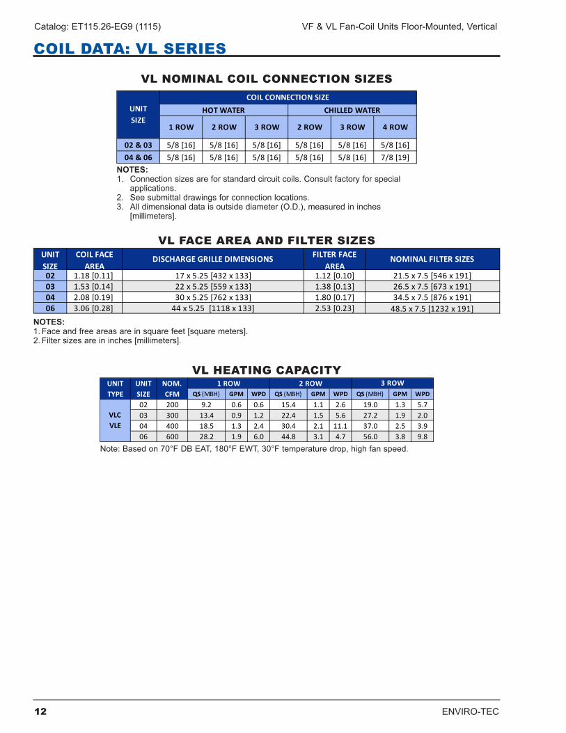
COIL DATA: VL SERIES
02 & 03 5/8 [16] 5/8 [16] 5/8 [16] 5/8 [16] 5/8 [16] 5/8 [16]04 & 06 5/8 [16] 5/8 [16] 5/8 [16] 5/8 [16] 5/8 [16] 7/8 [19]
UNIT SIZE
1 ROW 3 ROW 3 ROW
COIL CONNECTION SIZE
2 ROW 2 ROW
HOT WATER CHILLED WATER
4 ROW
NOTES:1 . Connection sizes are for standard circuit coils . Consult factory for special
applications .2. Seesubmittaldrawingsforconnectionlocations.3. Alldimensionaldataisoutsidediameter(O.D.),measuredininches
[millimeters].
UNIT SIZE
COIL FACE AREA
DISCHARGE GRILLE DIMENSIONS FILTER FACE AREA
NOMINAL FILTER SIZES
02 1.18 [0.11] 17 x 5.25 [432 x 133] 1.12 [0.10] 21.5 x 7.5 [546 x 191]03 1.53 [0.14] 22 x 5.25 [559 x 133] 1.38 [0.13] 26.5 x 7.5 [673 x 191]04 2.08 [0.19] 30 x 5.25 [762 x 133] 1.80 [0.17] 34.5 x 7.5 [876 x 191]06 3.06 [0.28] 44 x 5.25 [1118 x 133] 2.53 [0.23] 48.5 x 7.5 [1232 x 191]
NOTES:1.Faceandfreeareasareinsquarefeet[squaremeters].2.Filtersizesareininches[millimeters].
QS (MBH) GPM WPD QS (MBH) GPM WPD QS (MBH) GPM WPD
02 200 9.2 0.6 0.6 15.4 1.1 2.6 19.0 1.3 5.703 300 13.4 0.9 1.2 22.4 1.5 5.6 27.2 1.9 2.004 400 18.5 1.3 2.4 30.4 2.1 11.1 37.0 2.5 3.906 600 28.2 1.9 6.0 44.8 3.1 4.7 56.0 3.8 9.8
2 ROW 3 ROW
VLC VLE
UNIT TYPE
UNIT SIZE
NOM. CFM
1 ROW
Note:Basedon70°FDBEAT,180°FEWT,30°Ftemperaturedrop,highfanspeed.
VL NOMINAL COIL CONNECTION SIZES
VL FACE AREA AND FILTER SIZES
VL HEATING CAPACITY
ENVIRO-TEC 13
VF & VL Fan-Coil Units Floor-Mounted, Vertical Catalog: ET115.26-EG9 (1115)
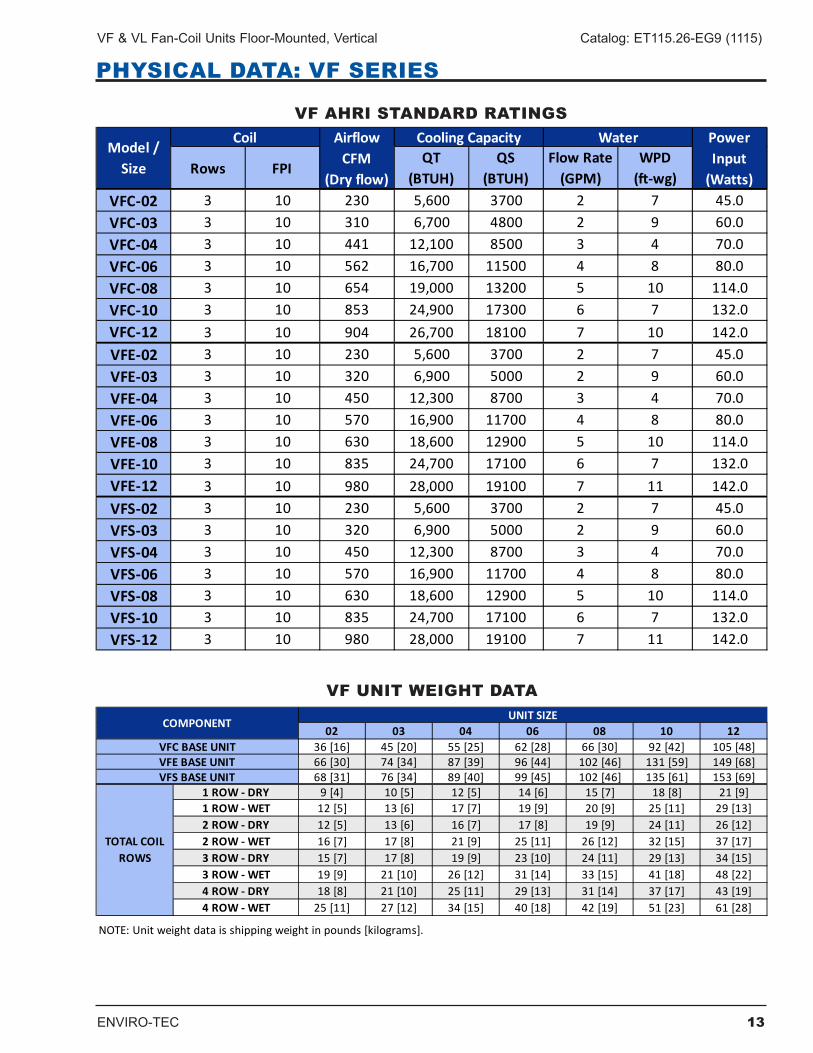
PHYSICAL DATA: VF SERIES
VF AHRI STANDARD RATINGS
VF UNIT WEIGHT DATA
02 03 04 06 08 10 1236 [16] 45 [20] 55 [25] 62 [28] 66 [30] 92 [42] 105 [48]66 [30] 74 [34] 87 [39] 96 [44] 102 [46] 131 [59] 149 [68]68 [31] 76 [34] 89 [40] 99 [45] 102 [46] 135 [61] 153 [69]
1 ROW - DRY 9 [4] 10 [5] 12 [5] 14 [6] 15 [7] 18 [8] 21 [9]1 ROW - WET 12 [5] 13 [6] 17 [7] 19 [9] 20 [9] 25 [11] 29 [13]2 ROW - DRY 12 [5] 13 [6] 16 [7] 17 [8] 19 [9] 24 [11] 26 [12]2 ROW - WET 16 [7] 17 [8] 21 [9] 25 [11] 26 [12] 32 [15] 37 [17]3 ROW - DRY 15 [7] 17 [8] 19 [9] 23 [10] 24 [11] 29 [13] 34 [15]3 ROW - WET 19 [9] 21 [10] 26 [12] 31 [14] 33 [15] 41 [18] 48 [22]4 ROW - DRY 18 [8] 21 [10] 25 [11] 29 [13] 31 [14] 37 [17] 43 [19]4 ROW - WET 25 [11] 27 [12] 34 [15] 40 [18] 42 [19] 51 [23] 61 [28]
NOTE: Unit weight data is shipping weight in pounds [kilograms].
VFS BASE UNIT
TOTAL COIL ROWS
COMPONENTUNIT SIZE
VFC BASE UNITVFE BASE UNIT
Rows FPIQT
(BTUH)QS
(BTUH)Flow Rate
(GPM)WPD
(ft-wg)VFC-02 3 10 230 5,600 3700 2 7 45.0VFC-03 3 10 310 6,700 4800 2 9 60.0VFC-04 3 10 441 12,100 8500 3 4 70.0VFC-06 3 10 562 16,700 11500 4 8 80.0VFC-08 3 10 654 19,000 13200 5 10 114.0VFC-10 3 10 853 24,900 17300 6 7 132.0VFC-12 3 10 904 26,700 18100 7 10 142.0VFE-02 3 10 230 5,600 3700 2 7 45.0VFE-03 3 10 320 6,900 5000 2 9 60.0VFE-04 3 10 450 12,300 8700 3 4 70.0VFE-06 3 10 570 16,900 11700 4 8 80.0VFE-08 3 10 630 18,600 12900 5 10 114.0VFE-10 3 10 835 24,700 17100 6 7 132.0VFE-12 3 10 980 28,000 19100 7 11 142.0VFS-02 3 10 230 5,600 3700 2 7 45.0VFS-03 3 10 320 6,900 5000 2 9 60.0VFS-04 3 10 450 12,300 8700 3 4 70.0VFS-06 3 10 570 16,900 11700 4 8 80.0VFS-08 3 10 630 18,600 12900 5 10 114.0VFS-10 3 10 835 24,700 17100 6 7 132.0VFS-12 3 10 980 28,000 19100 7 11 142.0
Power Input
(Watts)
Model / Size
Coil Airflow CFM
(Dry flow)
Cooling Capacity Water
14 ENVIRO-TEC
Catalog: ET115.26-EG9 (1115) VF & VL Fan-Coil Units Floor-Mounted, Vertical
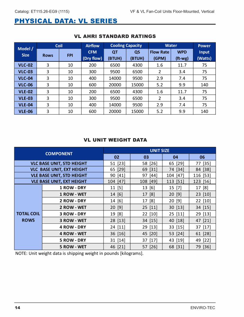
PHYSICAL DATA: VL SERIES
VL UNIT WEIGHT DATA
VL AHRI STANDARD RATINGS
Rows FPIQT
(BTUH)QS
(BTUH)Flow Rate
(GPM)WPD
(ft-wg)VLC-02 3 10 200 6500 4300 1.6 11.7 75VLC-03 3 10 300 9500 6500 2 3.4 75VLC-04 3 10 400 14000 9500 2.9 7.4 75VLC-06 3 10 600 20000 15000 5.2 9.9 140VLE-02 3 10 200 6500 4300 1.6 11.7 75VLE-03 3 10 300 9500 6500 2 3.4 75VLE-04 3 10 400 14000 9500 2.9 7.4 75VLE-06 3 10 600 20000 15000 5.2 9.9 140
Power Input
(Watts)
Model / Size
Coil Airflow CFM
(Dry flow)
Cooling Capacity Water
51 [23] 58 [26] 65 [29] 77 [35]65 [29] 69 [31] 74 [34] 84 [38]90 [41] 97 [44] 104 [47] 116 [53]
104 [47] 108 [49] 113 [51] 123 [56]1 ROW - DRY 11 [5] 13 [6] 15 [7] 17 [8]1 ROW - WET 14 [6] 17 [8] 20 [9] 23 [10]2 ROW - DRY 14 [6] 17 [8] 20 [9] 22 [10]2 ROW - WET 20 [9] 25 [11] 30 [13] 34 [15]3 ROW - DRY 19 [8] 22 [10] 25 [11] 29 [13]3 ROW - WET 28 [13] 34 [15] 40 [18] 47 [21]4 ROW - DRY 24 [11] 29 [13] 33 [15] 37 [17]4 ROW - WET 36 [16] 45 [20] 53 [24] 61 [28]5 ROW - DRY 31 [14] 37 [17] 43 [19] 49 [22]5 ROW - WET 46 [21] 57 [26] 68 [31] 79 [36]
NOTE: Unit weight data is shipping weight in pounds [kilograms].
TOTAL COIL ROWS
COMPONENT
VLC BASE UNIT, STD HEIGHTVLC BASE UNIT, EXT HEIGHTVLE BASE UNIT, STD HEIGHT
06UNIT SIZE
VLE BASE UNIT, EXT HEIGHT
02 03 04
ENVIRO-TEC 15
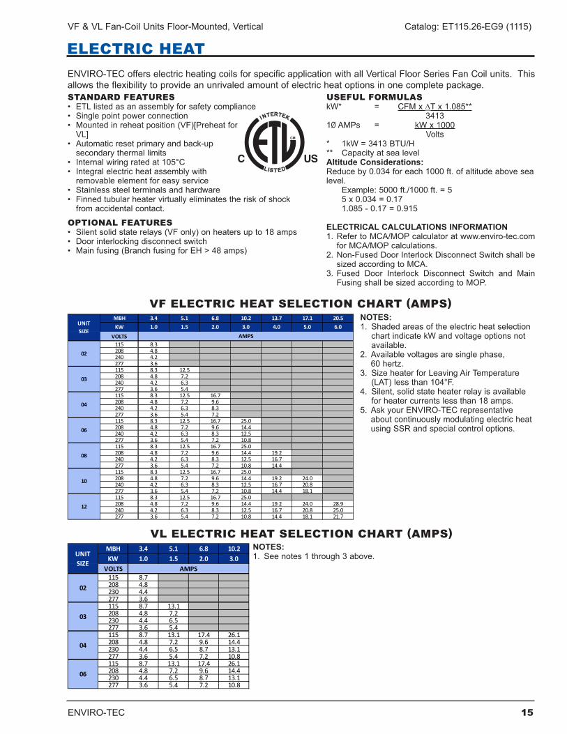
VF & VL Fan-Coil Units Floor-Mounted, Vertical Catalog: ET115.26-EG9 (1115)
NOTES:1 . Shaded areas of the electric heat selection
chartindicatekWandvoltageoptionsnotavailable.
2. Availablevoltagesaresinglephase, 60hertz.
3. SizeheaterforLeavingAirTemperature(LAT)lessthan104°F.
4. Silent,solidstateheaterrelayisavailablefor heater currents less than 18 amps .
5. AskyourENVIRO-TECrepresentativeaboutcontinuouslymodulatingelectricheatusing SSR and special control options .
VF ELECTRIC HEAT SELECTION CHART (AMPS)
STANDARD FEATURES• ETLlistedasanassemblyforsafetycompliance• Singlepointpowerconnection• Mountedinreheatposition(VF)[Preheatfor VL]• Automaticresetprimaryandback-up
secondary thermal limits• Internalwiringratedat105°C• Integralelectricheatassemblywith removableelementforeasyservice
• Stainlesssteelterminalsandhardware• Finnedtubularheatervirtuallyeliminatestheriskofshock
from accidental contact .
OPTIONAL FEATURES• Silentsolidstaterelays(VFonly)onheatersupto18amps• Doorinterlockingdisconnectswitch• Mainfusing(BranchfusingforEH>48amps)
USEFUL FORMULASkW* = CFM x ∆Tx1.085** 34131ØAMPs = kWx1000 Volts* 1kW=3413BTU/H** CapacityatsealevelAltitude Considerations:Reduceby0.034foreach1000ft.ofaltitudeabovesealevel. Example:5000ft./1000ft.=5 5x0.034=0.17 1.085-0.17=0.915
ELECTRICAL CALCULATIONS INFORMATION1. RefertoMCA/MOPcalculatoratwww.enviro-tec.com
forMCA/MOPcalculations.2. Non-FusedDoorInterlockDisconnectSwitchshallbe
sizedaccordingtoMCA.3. Fused Door Interlock Disconnect Switch and Main
FusingshallbesizedaccordingtoMOP.
ENVIRO-TECofferselectricheatingcoilsforspecificapplicationwithallVerticalFloorSeriesFanCoilunits.Thisallowstheflexibilitytoprovideanunrivaledamountofelectricheatoptionsinonecompletepackage.
ELECTRIC HEAT
MBH 3.4 5.1 6.8 10.2 13.7 17.1 20.5KW 1.0 1.5 2.0 3.0 4.0 5.0 6.0
VOLTS115 8.3208 4.8240 4.2277 3.6115 8.3 12.5208 4.8 7.2240 4.2 6.3277 3.6 5.4115 8.3 12.5 16.7208 4.8 7.2 9.6240 4.2 6.3 8.3277 3.6 5.4 7.2115 8.3 12.5 16.7 25.0208 4.8 7.2 9.6 14.4240 4.2 6.3 8.3 12.5277 3.6 5.4 7.2 10.8115 8.3 12.5 16.7 25.0208 4.8 7.2 9.6 14.4 19.2240 4.2 6.3 8.3 12.5 16.7277 3.6 5.4 7.2 10.8 14.4115 8.3 12.5 16.7 25.0208 4.8 7.2 9.6 14.4 19.2 24.0240 4.2 6.3 8.3 12.5 16.7 20.8277 3.6 5.4 7.2 10.8 14.4 18.1115 8.3 12.5 16.7 25.0208 4.8 7.2 9.6 14.4 19.2 24.0 28.9240 4.2 6.3 8.3 12.5 16.7 20.8 25.0277 3.6 5.4 7.2 10.8 14.4 18.1 21.7
08
10
12
UNIT SIZE
AMPS
02
03
04
06
MBH 3.4 5.1 6.8 10.2KW 1.0 1.5 2.0 3.0
VOLTS115 8.7208 4.8230 4.4277 3.6115 8.7 13.1208 4.8 7.2230 4.4 6.5277 3.6 5.4115 8.7 13.1 17.4 26.1208 4.8 7.2 9.6 14.4230 4.4 6.5 8.7 13.1277 3.6 5.4 7.2 10.8115 8.7 13.1 17.4 26.1208 4.8 7.2 9.6 14.4230 4.4 6.5 8.7 13.1277 3.6 5.4 7.2 10.8
04
06
UNIT SIZE
AMPS
02
03
VL ELECTRIC HEAT SELECTION CHART (AMPS)NOTES:1. Seenotes1through3above.
16 ENVIRO-TEC
Catalog: ET115.26-EG9 (1115) VF & VL Fan-Coil Units Floor-Mounted, Vertical
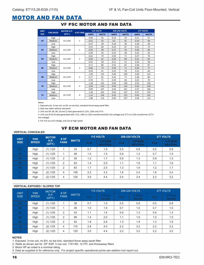
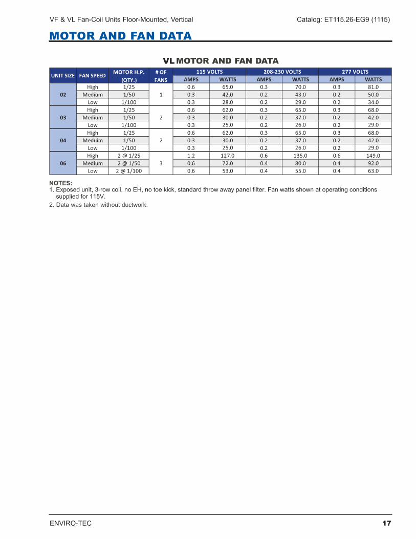
MOTOR AND FAN DATA
AMPS WATTS AMPS WATTS AMPS WATTSHigh 0.40 45 0.23 53 0.21 57
Medium 0.31 35 0.2 41 0.19 44Low 0.27 28 0.18 36 0.18 40High 0.55 60 0.33 67 0.31 73
Medium 0.43 48 0.27 54 0.26 60Low 0.40 43 0.25 49 0.24 54High 0.62 70 0.30 71 0.27 76
Meduim 0.56 61 0.24 60 0.21 65Low 0.54 58 0.21 52 0.20 58High 0.71 80 0.35 81 0.30 87
Medium 0.66 74 0.29 71 0.26 77Low 0.59 61 0.25 59 0.22 64High 1.03 114 0.46 109 0.40 114
Medium 0.77 81 0.32 77 0.28 80Low 0.70 71 0.29 66 0.25 70High 1.18 132 0.60 140 0.53 144
Medium 1.03 114 0.49 116 0.42 120Low 0.99 107 0.43 101 0.37 106High 1.26 142 0.63 147 0.57 154
Medium 1.14 126 0.53 125 0.45 131Low 1.08 114 0.46 107 0.40 114
Notes:1. Exposed unit, 3-row coil, no EH, no toe kick, standard throw away panel filter2. Data was taken without ductwork3. Unit size 04, 06, 08, 10 and 12 data generated at 115v, 230v and 277v
5. For FLA use unit voltage, and size at high speed
4. Unit size 02 & 03 data generated with 115v, 240v to 120v transformer(230v line voltage) and 277v to 120v transformer (277v line voltage)
10 4
12 4
04 2
06 2
08 2
(1) 1/20
(1) 1/20
(1) 1/10
(2) 1/20
(2) 1/20
208-230 VOLTS 277 VOLTS
02 1
03 1
UNIT SIZE
FAN SPEEDMOTOR H.P.
(QTY.)# OF FANS
115 VOLTS
(1) 1/50
(1) 1/20
VF PSC MOTOR AND FAN DATA
VERTICAL CONCEALED
UNIT SIZE
FAN SPEED
MOTOR H.P.
(QTY.)
# OF FANS WATTS
115 VOLTS 208-230 VOLTS 277 VOLTS
FLA 3-PHASE NEUTRAL FLA 3-PHASE
NEUTRAL FLA 3-PHASE NEUTRAL
02 High (1)1/25 1 34 0.7 1.0 0.5 0.8 0.5 0.8
03 High (1)1/25 1 48 1.0 1 .5 0.8 1 .2 0.7 1.0
04 High (1)1/25 2 55 1 .2 1 .7 0.9 1 .3 0.9 1 .3
06 High (1)1/25 2 63 1 .4 2.0 1 .1 1 .6 1 .1 1 .6
08 High (1)1/25 2 83 1 .7 2 .5 1 .3 1 .9 1 .2 1 .7
10 High (2)1/25 4 106 2 .2 3 .2 1 .6 2 .4 1 .6 2 .4
12 High (2)1/25 4 120 3.0 4 .4 2 .4 3 .4 2 .2 3 .2
VERTICAL EXPOSED / SLOPED TOP
UNITSIZE
FANSPEED
MOTOR H .P .
(QTY .)
# OF FANS WATTS
115VOLTS 208-230VOLTS 277VOLTS
FLA 3-Phase Neutral FLA 3-Phase
Neutral FLA 3-Phase Neutral
02 High (1)1/25 1 38 0.7 1.0 0.5 0.8 0.5 0.8
03 High (1)1/25 1 48 1.0 1 .5 0.7 1.0 0.7 1.0
04 High (1)1/25 2 53 1 .1 1 .6 0.9 1 .3 0.9 1 .3
06 High (1)1/25 2 66 1 .4 2.0 1 .1 1 .6 1.0 1 .5
08 High (1)1/25 2 93 1 .8 2 .6 1 .3 1 .9 1 .3 1 .9
10 High (2)1/25 4 115 2 .8 4.0 2 .2 3 .2 2 .2 3 .2
12 High (2)1/25 4 120 3.0 4 .4 2 .2 3 .2 2 .2 3 .2 NOTES: 1.Exposed,3-rowcoil,noEH,notoekick,standardthrowawaypanelfilter 2.Wattsasshownarefor.05"ESP,3rowcoil,115/1/60,12FPI,andthrowawayfilters 3 . Motor HP as noted is a nominal rating 4.Dataassuppliedisforreferenceonly.Forprojectspecificoperationalpointsseeseletiontoolreportout.
VF ECM MOTOR AND FAN DATA
ENVIRO-TEC 17
VF & VL Fan-Coil Units Floor-Mounted, Vertical Catalog: ET115.26-EG9 (1115)
MOTOR AND FAN DATA
��
��������������������� ������������������������������������� �� ��������������������� �������� ������������������������������������������������
18 ENVIRO-TEC
Catalog: ET115.26-EG9 (1115) VF & VL Fan-Coil Units Floor-Mounted, Vertical
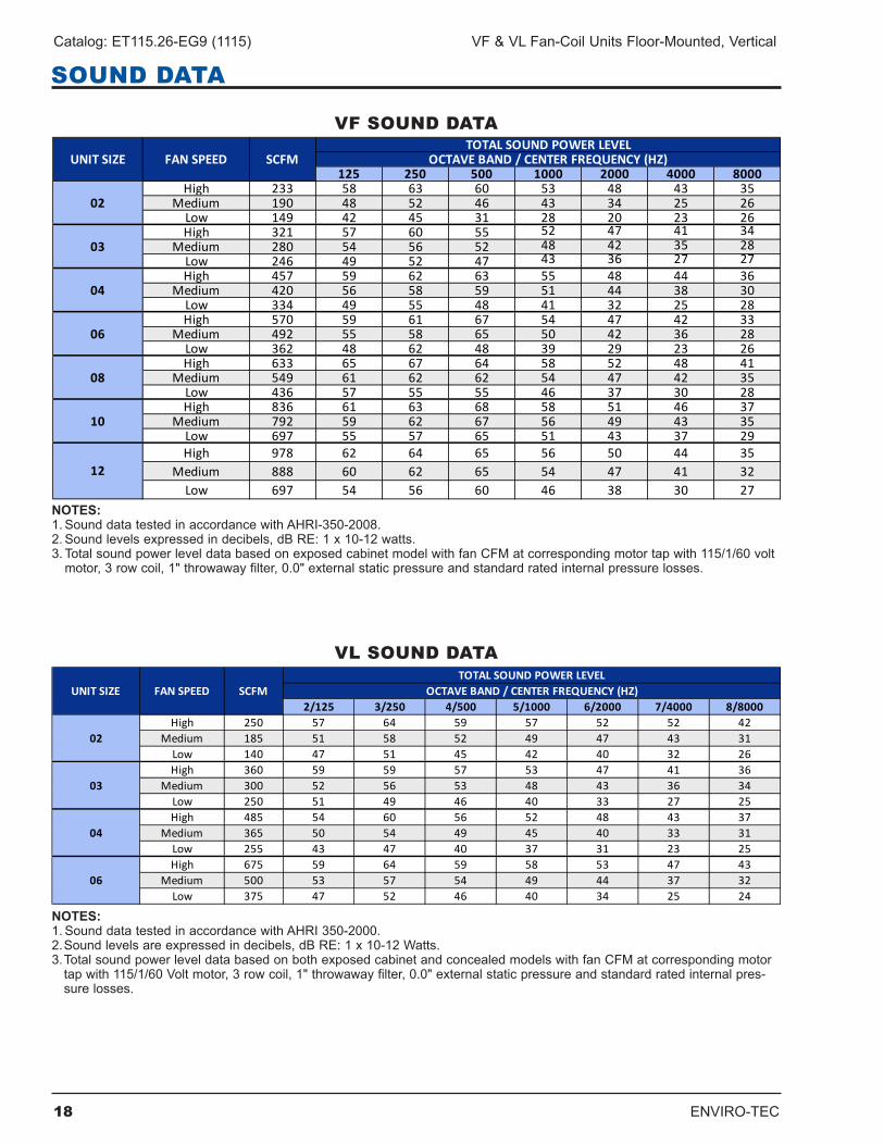
VF SOUND DATA
125 250 500 1000 2000 4000 8000High 233 58 63 60 53 48 43 35
Medium 190 48 52 46 43 34 25 26Low 149 42 45 31 28 20 23 26High 321 57 60 55 52 47 41 34
Medium 280 54 56 52 48 42 35 28Low 246 49 52 47 43 36 27 27High 457 59 62 63 55 48 44 36
Medium 420 56 58 59 51 44 38 30Low 334 49 55 48 41 32 25 28High 570 59 61 67 54 47 42 33
Medium 492 55 58 65 50 42 36 28Low 362 48 62 48 39 29 23 26High 633 65 67 64 58 52 48 41
Medium 549 61 62 62 54 47 42 35Low 436 57 55 55 46 37 30 28High 836 61 63 68 58 51 46 37
Medium 792 59 62 67 56 49 43 35Low 697 55 57 65 51 43 37 29High 978 62 64 65 56 50 44 35
Medium 888 60 62 65 54 47 41 32Low 697 54 56 60 46 38 30 27
UNIT SIZE FAN SPEED SCFMTOTAL SOUND POWER LEVEL
OCTAVE BAND / CENTER FREQUENCY (HZ)
12
02
03
04
06
08
10
NOTES:1.SounddatatestedinaccordancewithAHRI-350-2008.2.Soundlevelsexpressedindecibels,dBRE:1x10-12watts.3.TotalsoundpowerleveldatabasedonexposedcabinetmodelwithfanCFMatcorrespondingmotortapwith115/1/60voltmotor,3rowcoil,1"throwawayfilter,0.0"externalstaticpressureandstandardratedinternalpressurelosses.
VL SOUND DATA
2/125 3/250 4/500 5/1000 6/2000 7/4000 8/8000High 250 57 64 59 57 52 52 42
Medium 185 51 58 52 49 47 43 31Low 140 47 51 45 42 40 32 26High 360 59 59 57 53 47 41 36
Medium 300 52 56 53 48 43 36 34Low 250 51 49 46 40 33 27 25High 485 54 60 56 52 48 43 37
Medium 365 50 54 49 45 40 33 31Low 255 43 47 40 37 31 23 25High 675 59 64 59 58 53 47 43
Medium 500 53 57 54 49 44 37 32Low 375 47 52 46 40 34 25 24
02
04
06
03
TOTAL SOUND POWER LEVELOCTAVE BAND / CENTER FREQUENCY (HZ)UNIT SIZE FAN SPEED SCFM
NOTES:1.SounddatatestedinaccordancewithAHRI350-2000.2.Soundlevelsareexpressedindecibels,dBRE:1x10-12Watts.3.TotalsoundpowerleveldatabasedonbothexposedcabinetandconcealedmodelswithfanCFMatcorrespondingmotortapwith115/1/60Voltmotor,3rowcoil,1"throwawayfilter,0.0"externalstaticpressureandstandardratedinternalpres-sure losses .
SOUND DATA
ENVIRO-TEC 19
VF & VL Fan-Coil Units Floor-Mounted, Vertical Catalog: ET115.26-EG9 (1115)
DIMENSIONAL DATA: VF SERIES
A
9-1/4"[235]
25"[635]
2-1/4"[57]
9-1/4"[235]
7-1/2"[190]4-3/16"
[106]
3/4" M.P.T. AUXILIARYDRAIN PAN CONNECTION
FILTER
CONTROLENCLOSURE
SUPPLYAIR
RETURN AIR
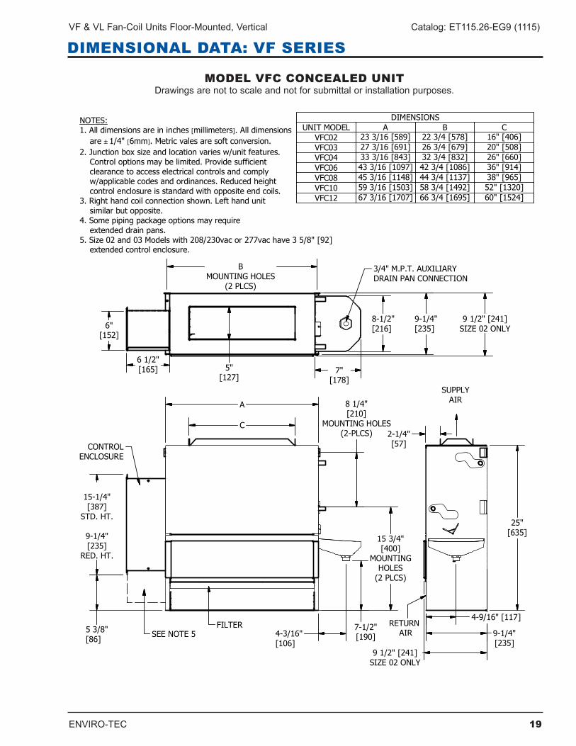
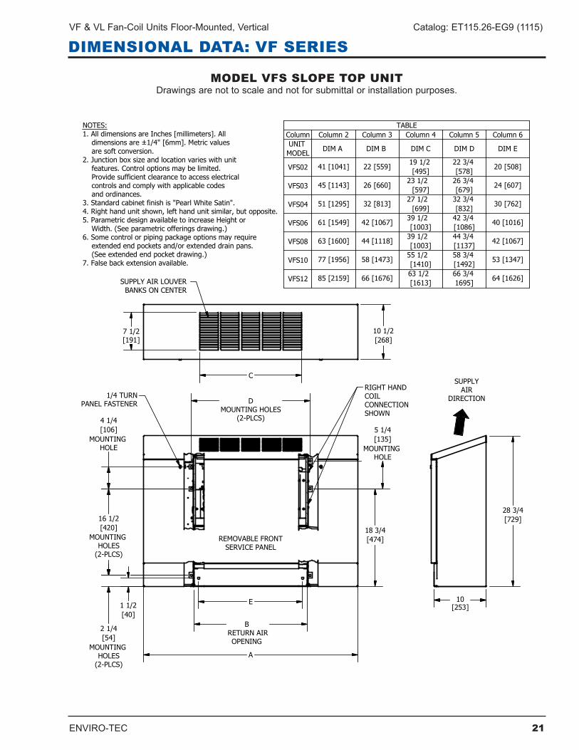
DIMENSIONSUNIT MODEL A B C
VFC02 23 3/16 [589] 22 3/4 [578] 16" [406]VFC03 27 3/16 [691] 26 3/4 [679] 20" [508]VFC04 33 3/16 [843] 32 3/4 [832] 26" [660]VFC06 43 3/16 [1097] 42 3/4 [1086] 36" [914]VFC08 45 3/16 [1148] 44 3/4 [1137] 38" [965]VFC10 59 3/16 [1503] 58 3/4 [1492] 52" [1320]VFC12 67 3/16 [1707] 66 3/4 [1695] 60" [1524]
BMOUNTING HOLES
(2 PLCS)
NOTES:1. All dimensions are in inches [millimeters]. All dimensions are 1/4" [6mm]. Metric vales are soft conversion.2. Junction box size and location varies w/unit features. Control options may be limited. Provide sufficient clearance to access electrical controls and comply w/applicable codes and ordinances. Reduced height control enclosure is standard with opposite end coils.3. Right hand coil connection shown. Left hand unit similar but opposite.4. Some piping package options may require extended drain pans.5. Size 02 and 03 Models with 208/230vac or 277vac have 3 5/8" [92] extended control enclosure.
4-9/16" [117]
8-1/2"[216]
7"[178]
5 3/8"[86]
SEE NOTE 5
9 1/2" [241]SIZE 02 ONLY
9 1/2" [241]SIZE 02 ONLY
15-1/4"[387]
STD. HT.
9-1/4"[235]
RED. HT.
15 3/4"[400]
MOUNTINGHOLES
(2 PLCS)
8 1/4"[210]
MOUNTING HOLES(2-PLCS)
C
6"[152]
6 1/2"[165] 5"
[127]
MODEL VFC CONCEALED UNITDrawingsarenottoscaleandnotforsubmittalorinstallationpurposes.
20 ENVIRO-TEC
Catalog: ET115.26-EG9 (1115) VF & VL Fan-Coil Units Floor-Mounted, Vertical
DIMENSIONAL DATA: VF SERIES
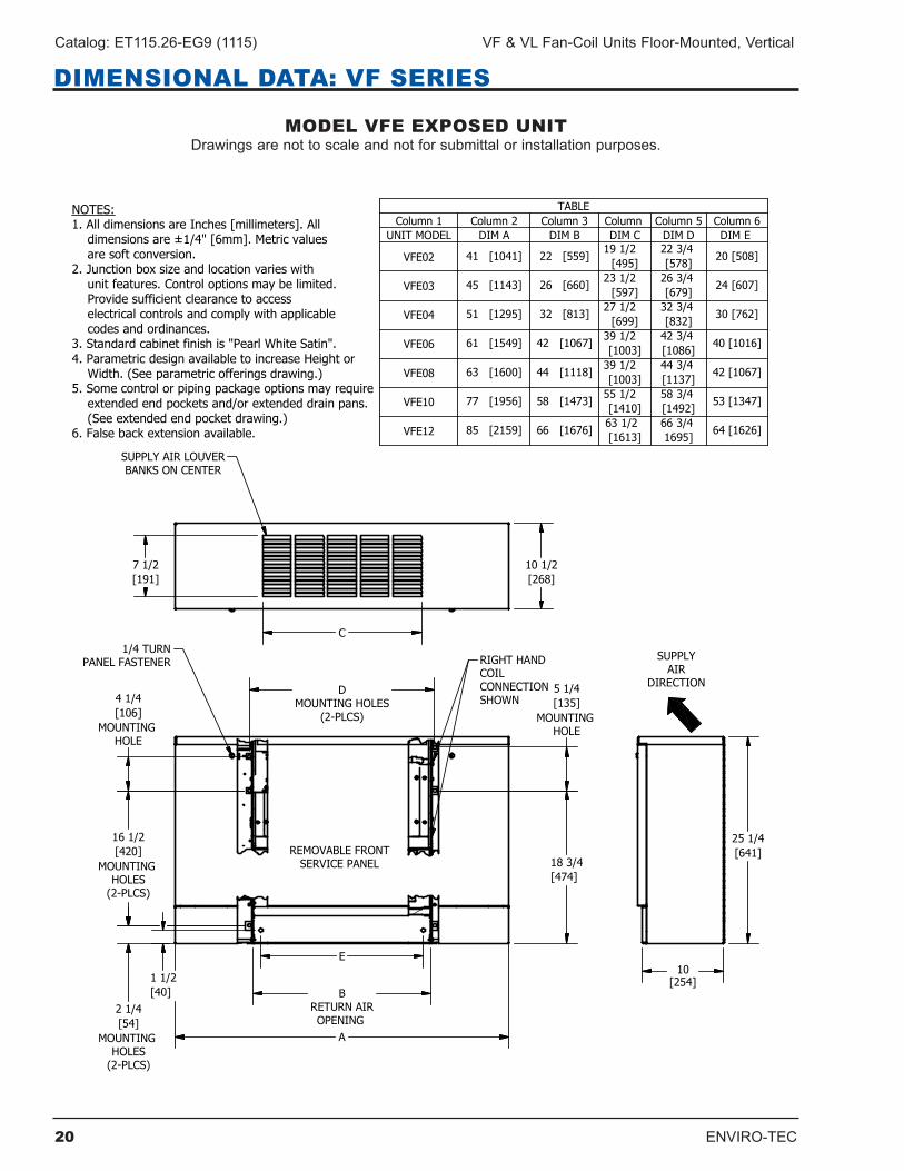
MODEL VFE EXPOSED UNITDrawingsarenottoscaleandnotforsubmittalorinstallationpurposes.
ENVIRO-TEC 21
VF & VL Fan-Coil Units Floor-Mounted, Vertical Catalog: ET115.26-EG9 (1115)
DIMENSIONAL DATA: VF SERIES
MODEL VFS SLOPE TOP UNITDrawingsarenottoscaleandnotforsubmittalorinstallationpurposes.
22 ENVIRO-TEC
Catalog: ET115.26-EG9 (1115) VF & VL Fan-Coil Units Floor-Mounted, Vertical
DIMENSIONAL DATA: VF SERIES
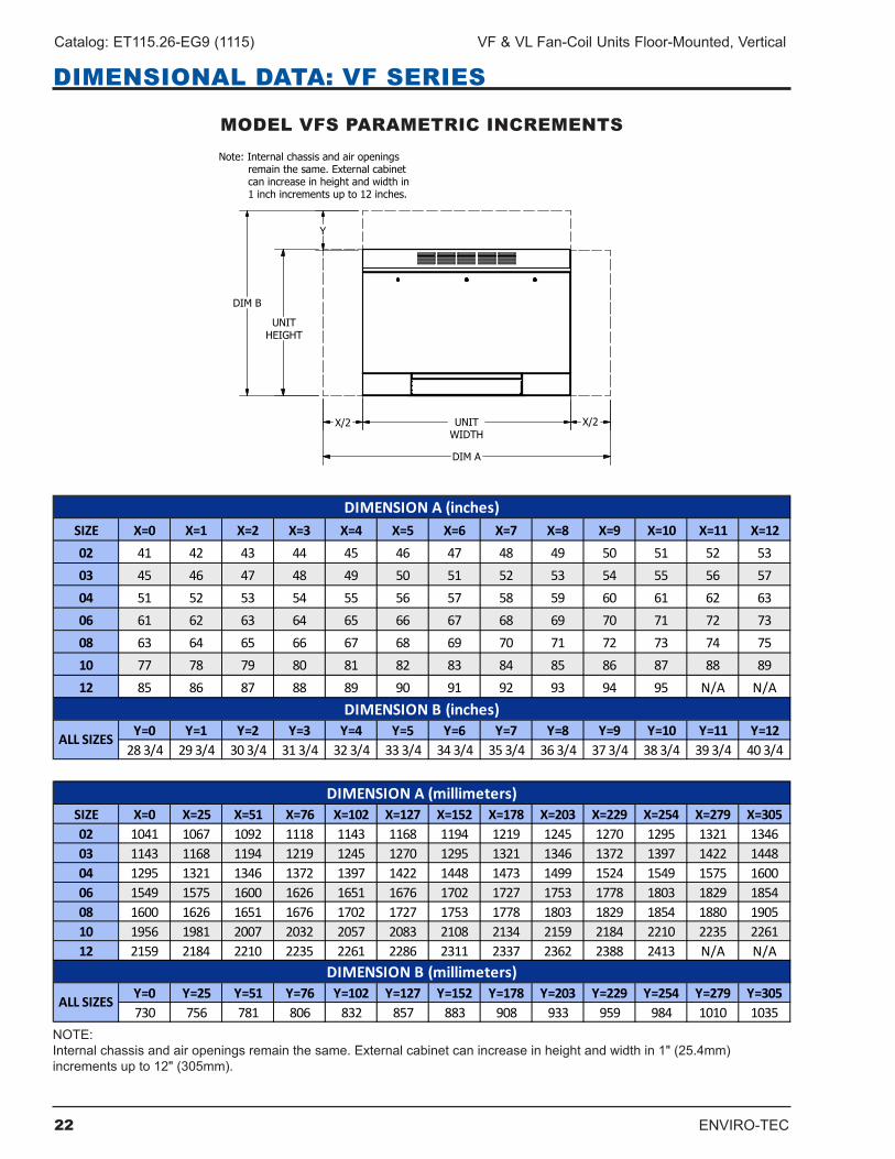
MODEL VFS PARAMETRIC INCREMENTS
UNITWIDTH
Note: Internal chassis and air openings remain the same. External cabinet can increase in height and width in 1 inch increments up to 12 inches.
X/2
DIM A
DIM B
UNITHEIGHT
X/2
Y
SIZE X=0 X=1 X=2 X=3 X=4 X=5 X=6 X=7 X=8 X=9 X=10 X=11 X=1202 41 42 43 44 45 46 47 48 49 50 51 52 5303 45 46 47 48 49 50 51 52 53 54 55 56 5704 51 52 53 54 55 56 57 58 59 60 61 62 6306 61 62 63 64 65 66 67 68 69 70 71 72 7308 63 64 65 66 67 68 69 70 71 72 73 74 7510 77 78 79 80 81 82 83 84 85 86 87 88 8912 85 86 87 88 89 90 91 92 93 94 95 N/A N/A
Y=0 Y=1 Y=2 Y=3 Y=4 Y=5 Y=6 Y=7 Y=8 Y=9 Y=10 Y=11 Y=1228 3/4 29 3/4 30 3/4 31 3/4 32 3/4 33 3/4 34 3/4 35 3/4 36 3/4 37 3/4 38 3/4 39 3/4 40 3/4
SIZE X=0 X=25 X=51 X=76 X=102 X=127 X=152 X=178 X=203 X=229 X=254 X=279 X=30502 1041 1067 1092 1118 1143 1168 1194 1219 1245 1270 1295 1321 134603 1143 1168 1194 1219 1245 1270 1295 1321 1346 1372 1397 1422 144804 1295 1321 1346 1372 1397 1422 1448 1473 1499 1524 1549 1575 160006 1549 1575 1600 1626 1651 1676 1702 1727 1753 1778 1803 1829 185408 1600 1626 1651 1676 1702 1727 1753 1778 1803 1829 1854 1880 190510 1956 1981 2007 2032 2057 2083 2108 2134 2159 2184 2210 2235 226112 2159 2184 2210 2235 2261 2286 2311 2337 2362 2388 2413 N/A N/A
Y=0 Y=25 Y=51 Y=76 Y=102 Y=127 Y=152 Y=178 Y=203 Y=229 Y=254 Y=279 Y=305730 756 781 806 832 857 883 908 933 959 984 1010 1035
ALL SIZES
DIMENSION A (inches)
DIMENSION B (inches)
ALL SIZES
DIMENSION A (millimeters)
DIMENSION B (millimeters)
NOTE: Internalchassisandairopeningsremainthesame.Externalcabinetcanincreaseinheightandwidthin1"(25.4mm) incrementsupto12"(305mm).
ENVIRO-TEC 23
VF & VL Fan-Coil Units Floor-Mounted, Vertical Catalog: ET115.26-EG9 (1115)
DIMENSIONAL DATA: VF SERIES
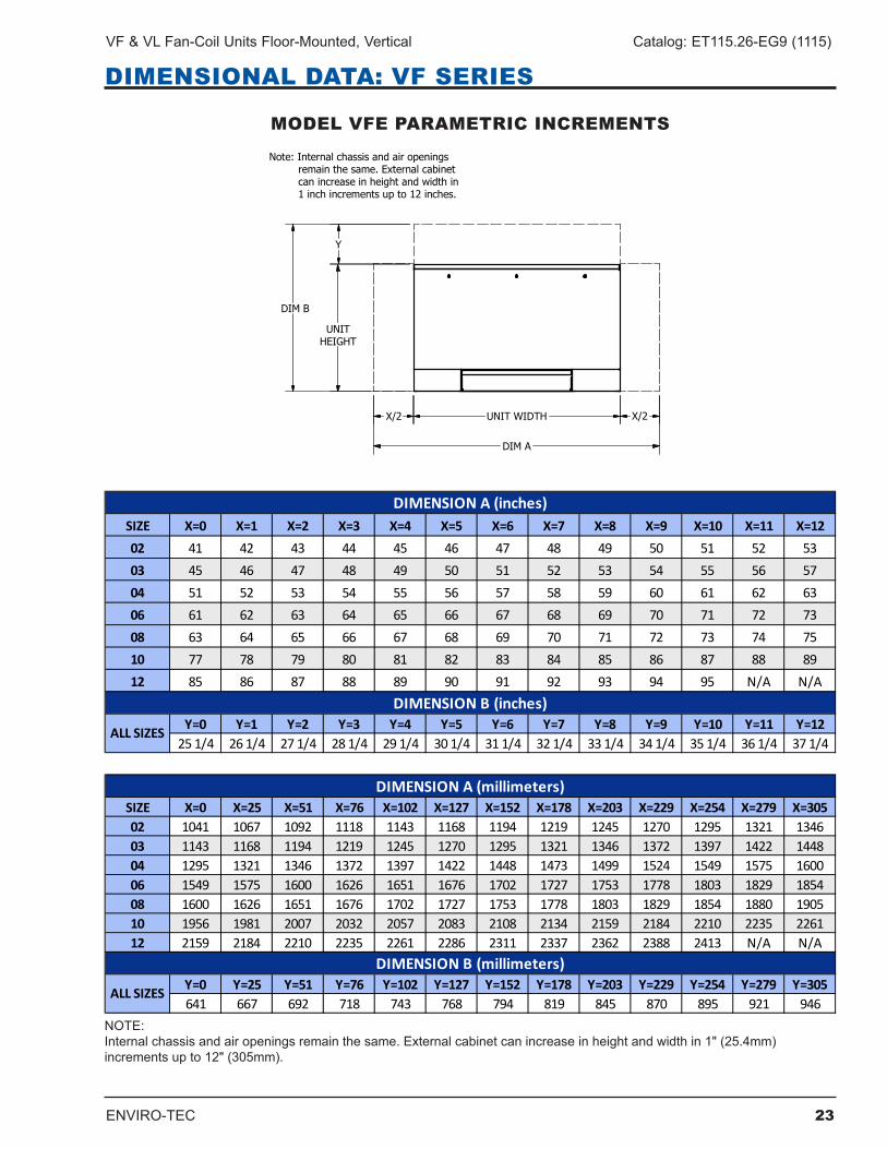
MODEL VFE PARAMETRIC INCREMENTS
UNIT WIDTH
Note: Internal chassis and air openings remain the same. External cabinet can increase in height and width in 1 inch increments up to 12 inches.
X/2
DIM A
DIM B
UNITHEIGHT
Y
X/2
SIZE X=0 X=1 X=2 X=3 X=4 X=5 X=6 X=7 X=8 X=9 X=10 X=11 X=1202 41 42 43 44 45 46 47 48 49 50 51 52 5303 45 46 47 48 49 50 51 52 53 54 55 56 5704 51 52 53 54 55 56 57 58 59 60 61 62 6306 61 62 63 64 65 66 67 68 69 70 71 72 7308 63 64 65 66 67 68 69 70 71 72 73 74 7510 77 78 79 80 81 82 83 84 85 86 87 88 8912 85 86 87 88 89 90 91 92 93 94 95 N/A N/A
Y=0 Y=1 Y=2 Y=3 Y=4 Y=5 Y=6 Y=7 Y=8 Y=9 Y=10 Y=11 Y=1225 1/4 26 1/4 27 1/4 28 1/4 29 1/4 30 1/4 31 1/4 32 1/4 33 1/4 34 1/4 35 1/4 36 1/4 37 1/4
SIZE X=0 X=25 X=51 X=76 X=102 X=127 X=152 X=178 X=203 X=229 X=254 X=279 X=30502 1041 1067 1092 1118 1143 1168 1194 1219 1245 1270 1295 1321 134603 1143 1168 1194 1219 1245 1270 1295 1321 1346 1372 1397 1422 144804 1295 1321 1346 1372 1397 1422 1448 1473 1499 1524 1549 1575 160006 1549 1575 1600 1626 1651 1676 1702 1727 1753 1778 1803 1829 185408 1600 1626 1651 1676 1702 1727 1753 1778 1803 1829 1854 1880 190510 1956 1981 2007 2032 2057 2083 2108 2134 2159 2184 2210 2235 226112 2159 2184 2210 2235 2261 2286 2311 2337 2362 2388 2413 N/A N/A
Y=0 Y=25 Y=51 Y=76 Y=102 Y=127 Y=152 Y=178 Y=203 Y=229 Y=254 Y=279 Y=305641 667 692 718 743 768 794 819 845 870 895 921 946
ALL SIZES
DIMENSION A (inches)
DIMENSION B (inches)
ALL SIZES
DIMENSION A (millimeters)
DIMENSION B (millimeters)
NOTE: Internalchassisandairopeningsremainthesame.Externalcabinetcanincreaseinheightandwidthin1"(25.4mm) incrementsupto12"(305mm).
24 ENVIRO-TEC
Catalog: ET115.26-EG9 (1115) VF & VL Fan-Coil Units Floor-Mounted, Vertical
DIMENSIONAL DATA: VF SERIES
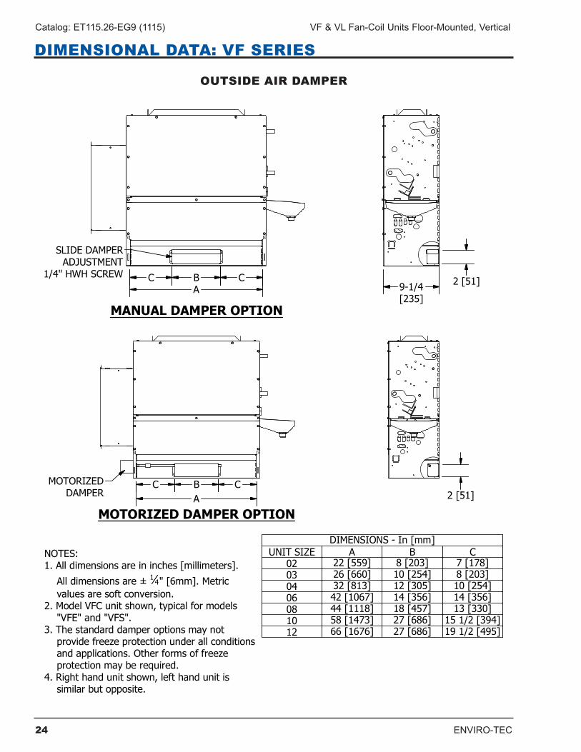
OUTSIDE AIR DAMPER
MOTORIZED DAMPER OPTION
MANUAL DAMPER OPTION
A
DIMENSIONS - In [mm]UNIT SIZE A B C
02 22 [559] 8 [203] 7 [178]03 26 [660] 10 [254] 8 [203]04 32 [813] 12 [305] 10 [254]06 42 [1067] 14 [356] 14 [356]08 44 [1118] 18 [457] 13 [330]10 58 [1473] 27 [686] 15 1/2 [394]12 66 [1676] 27 [686] 19 1/2 [495]
A
B CC
B CC
9-1/4[235]
2 [51]
2 [51]
SLIDE DAMPERADJUSTMENT
1/4" HWH SCREW
MOTORIZEDDAMPER
NOTES:1. All dimensions are in inches [millimeters].
All dimensions are ± 1 4" [6mm]. Metric values are soft conversion.2. Model VFC unit shown, typical for models "VFE" and "VFS".3. The standard damper options may not provide freeze protection under all conditions and applications. Other forms of freeze protection may be required.4. Right hand unit shown, left hand unit is similar but opposite.
ENVIRO-TEC 25
VF & VL Fan-Coil Units Floor-Mounted, Vertical Catalog: ET115.26-EG9 (1115)
DIMENSIONAL DATA: VF SERIES
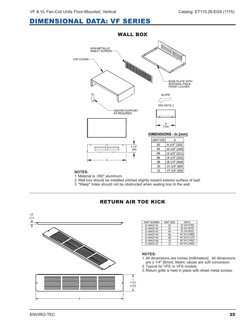
WALL BOX
RETURN AIR TOE KICK
NOTES:1.Materialis.050"aluminum.2.Wallboxshouldbeinstalledpitchedslightlytowardexteriorsurfaceofwall.3."Weep"holesshouldnotbeobstructedwhensealingboxtothewall.
NOTES:1.Alldimensionsareinches[millimeters].Alldimensionsare±1/4"[6mm].Metricvaluesaresoftconversion.
2 . Typical for VFE or VFS models .3.Returngrilleisheldinplacewithsheetmetalscrews.
26 ENVIRO-TEC
Catalog: ET115.26-EG9 (1115) VF & VL Fan-Coil Units Floor-Mounted, Vertical
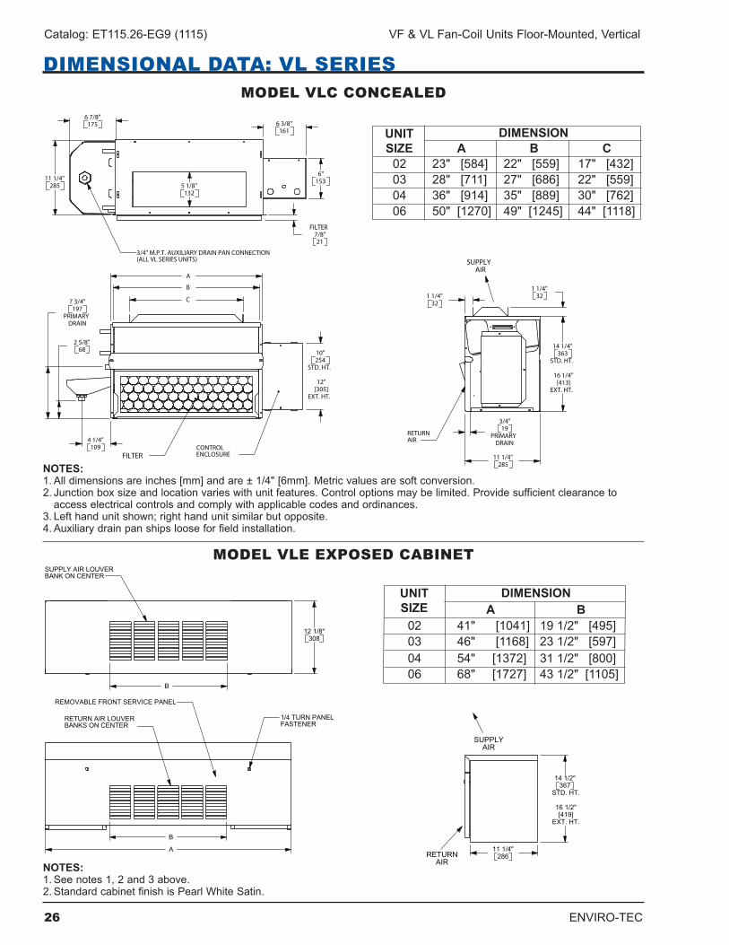
DIMENSIONAL DATA: VL SERIESMODEL VLC CONCEALED
11 1/4"285
6 7/8"175 6 3/8"
161
6"153
5 1/8"132
7/8"21
FILTER
3/4" M.P.T. AUXILIARY DRAIN PAN CONNECTION(ALL VL SERIES UNITS)
DIMENSIONUNITSIZE
02 23" [584] 22" [559] 17" [432] 03 28" [711] 27" [686] 22" [559] 04 36" [914] 35" [889] 30" [762] 06 50" [1270] 49" [1245] 44" [1118]
A B C
C
A
B
2 5/8"68
4 1/4"109
10"
STD. HT.
12"[305]
EXT. HT.
254
7 3/4"
PRIMARYDRAIN
197
FILTERCONTROLENCLOSURE
14 1/4"
STD. HT.
16 1/4"[413]
EXT. HT.
363
11 1/4"285
1 1/4"32
3/4"
PRIMARYDRAIN
19
1 1/4"32
RETURNAIR
SUPPLYAIR
NOTES:1.Alldimensionsareinches[mm]andare±1/4"[6mm].Metricvaluesaresoftconversion.2.Junctionboxsizeandlocationvarieswithunitfeatures.Controloptionsmaybelimited.Providesufficientclearancetoaccesselectricalcontrolsandcomplywithapplicablecodesandordinances.
3.Lefthandunitshown;righthandunitsimilarbutopposite.4.Auxiliarydrainpanshipslooseforfieldinstallation.
MODEL VLE EXPOSED CABINET
B
12 1/8"308
SUPPLY AIR LOUVER BANK ON CENTER
DIMENSIONUNITSIZE
02 41" [1041] 19 1/2" [495] 03 46" [1168] 23 1/2" [597] 04 54" [1372] 31 1/2" [800] 06 68" [1727] 43 1/2" [1105]
A B
A
B
1/4 TURN PANEL FASTENER
REMOVABLE FRONT SERVICE PANEL
RETURN AIR LOUVER BANKS ON CENTER
11 1/4"286
14 1/2"
STD. HT.
16 1/2"[419]
EXT. HT.
367
SUPPLYAIR
RETURNAIRNOTES:
1.Seenotes1,2and3above.2.StandardcabinetfinishisPearlWhiteSatin.
ENVIRO-TEC 27
VF & VL Fan-Coil Units Floor-Mounted, Vertical Catalog: ET115.26-EG9 (1115)
28 ENVIRO-TEC
Catalog: ET115.26-EG9 (1115) VF & VL Fan-Coil Units Floor-Mounted, Vertical
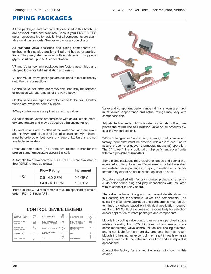
PIPING PACKAGES
Allthepackagesandcomponentsdescribedinthisbrochureareoptional,extracostfeatures.ConsultyourENVIRO-TECsalesrepresentativefordetails.Notallcomponentsareavail-ableonallunitmodels.Seevalvepackagecodecharts.
All standard valve packages and piping components de-scribed in thiscatalogare forchilledandhotwaterapplica-tions.Theymayalso beusedwith ethyleneandpropyleneglycolsolutionsupto50%concentration.
VFandVLfancoilunitpackagesarefactoryassembledandshippedlooseforfieldinstallationandwiring.
VFandVLunitvalvepackagesaredesignedtomountdirectlyonto the coil connections .
Controlvalveactuatorsareremovable,andmaybeservicedorreplacedwithoutremovalofthevalvebody.
Controlvalvesarepipednormallyclosedtothecoil.Controlvalvesareavailablenormallyopen.
3-Waycontrolvalvesarepipedasmixingvalves.
Allballisolationvalvesarefurnishedwithanadjustablemem-orystopfeatureandmaybeusedasabalancingvalve.
Optionalunionsareinstalledatthewatercoil,andareavail-ableonVAVproducts,andallfancoilunitsexceptVH.Unionsmustbeorderedonbothcoilsof4-pipeunits.Unionsarenotavailableseparately.
Pressure/temperature(P/T)portsare located tomonitor thepressure and temperature across the coil .
Automaticfixedflowcontrols(FC,FCN,FCS)areavailableinflow(GPM)ratingsasfollows:
IndividualcoilGPMrequirementsmustbespecifiedattimeoforder.FC=2-8psigAFS.
CONTROL DEVICE LEGEND
Valveandcomponentperformanceratingsshownaremaxi-mumvalues.Appearance and actual ratingsmay varywithcomponent size .
Adjustableflowsetter (AFS) is rated for fullshut-offandre-placesthereturn lineball isolationvalveonallproductsex-cept the VH fan coil unit .
2-Pipe "change-over"unitsusinga2-waycontrolvalveandfactorythermostatmustbeorderedwitha¼""bleed"linetoassure proper changeover thermostat (aquastat) operation.The¼""bleed"lineisoptionalon2-pipe"changeover"unitswithfieldprovidedthermostats.
Somepipingpackagesmayrequireextendedendpocketwithextendedauxiliarydrainpan.Requirementsforfieldfurnishedandinstalledvalvepackageandpipinginsulationmustbede-terminedbyothersonanindividualapplicationbasis.
Actuatorssuppliedwithfactorymountedpipingpackagesin-cludecolor codedplugandplayconnectionswith insulatedwiretoconnecttorelayboard.
The valve packagepiping and component details shown inthis catalog are for standard valves and components. Thesuitabilityofallvalvepackagesandcomponentsmustbede-termined by others based on individual application require-ments.ENVIRO-TECassumesnoresponsibilityforselectionand/orapplicationofvalvepackagesandcomponents.
Modulatingcoolingvalvecontrolcanincreasepartloadspacerelative humidity. ENVIRO-TEC does not encourage or en-dorsemodulatingvalvecontrol for fancoilcoolingsystems,and isnot liable forhighhumidityproblemsthatmayresult.Modulatingheatingvalvecontrolmayresultinlowleavingairtemperatureswhilethevalvereducesflowandassetpointisapproached .
Contact the factory for any requirements not shown in thiscatalog .
Flow Rating Increment
0.5-4.0GPM 0.5GPM >4.0-6.0GPM 1.0GPM
1/2"
ENVIRO-TEC 29
VF & VL Fan-Coil Units Floor-Mounted, Vertical Catalog: ET115.26-EG9 (1115)
PIPING PACKAGES
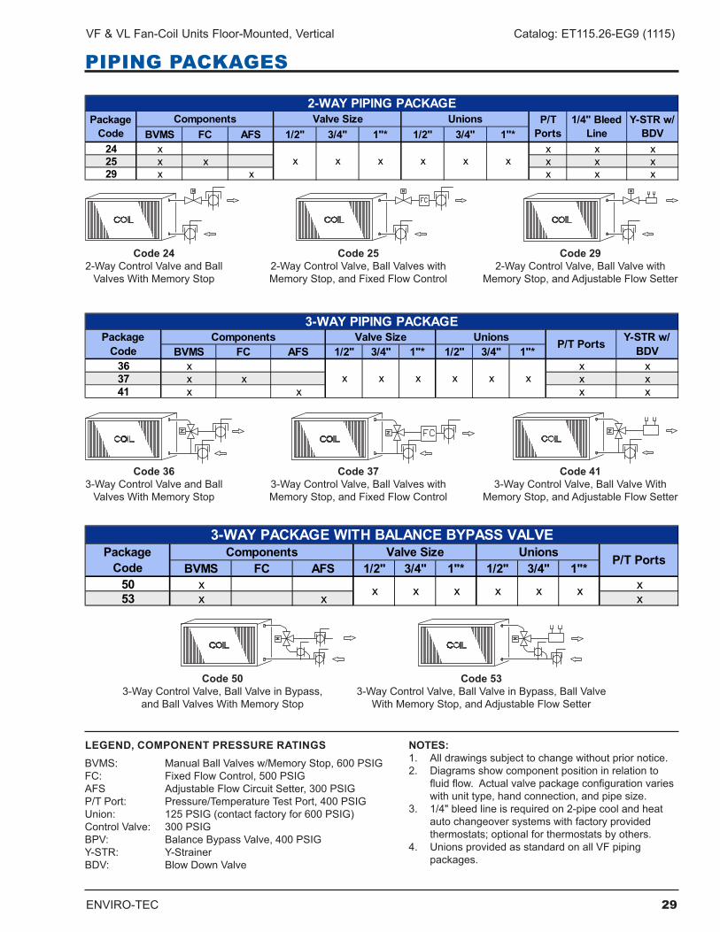
BVMS FC AFS 1/2" 3/4" 1"* 1/2" 3/4" 1"*24 x x x x25 x x x x x29 x x x x x
Y-STR w/ BDV
2-WAY PIPING PACKAGE
x
P/T Ports
xxx
ComponentsPackage Code
UnionsValve Size
x x
1/4" Bleed Line
BVMS FC AFS 1/2" 3/4" 1"* 1/2" 3/4" 1"*36 x x x37 x x x x41 x x x x
Y-STR w/ BDV
3-WAY PIPING PACKAGE
x
P/T PortsUnions
x x
Package Code
Valve SizeComponents
x x x
BVMS FC AFS 1/2" 3/4" 1"* 1/2" 3/4" 1"*50 x x53 x x x
P/T PortsComponentsPackage Code
3-WAY PACKAGE WITH BALANCE BYPASS VALVE
x x x
Unions
x x x
Valve Size
Code 242-WayControlValveandBallValvesWithMemoryStop
Code 252-WayControlValve,BallValveswithMemoryStop,andFixedFlowControl
Code 292-WayControlValve,BallValvewith
MemoryStop,andAdjustableFlowSetter
Code 363-WayControlValveandBallValvesWithMemoryStop
Code 373-WayControlValve,BallValveswithMemoryStop,andFixedFlowControl
Code 413-WayControlValve,BallValveWith
MemoryStop,andAdjustableFlowSetter
Code 503-WayControlValve,BallValveinBypass,
andBallValvesWithMemoryStop
Code 533-WayControlValve,BallValveinBypass,BallValve
WithMemoryStop,andAdjustableFlowSetter
LEGEND, COMPONENT PRESSURE RATINGSBVMS: ManualBallValvesw/MemoryStop,600PSIGFC: FixedFlowControl,500PSIGAFS AdjustableFlowCircuitSetter,300PSIGP/TPort: Pressure/TemperatureTestPort,400PSIGUnion: 125PSIG(contactfactoryfor600PSIG)ControlValve: 300PSIGBPV: BalanceBypassValve,400PSIGY-STR: Y-StrainerBDV: BlowDownValve
NOTES:1. Alldrawingssubjecttochangewithoutpriornotice.2. Diagramsshowcomponentpositioninrelationto
fluidflow.Actualvalvepackageconfigurationvarieswithunittype,handconnection,andpipesize.
3. 1/4"bleedlineisrequiredon2-pipecoolandheatautochangeoversystemswithfactoryprovided thermostats;optionalforthermostatsbyothers.
4. UnionsprovidedasstandardonallVFpiping packages .
30 ENVIRO-TEC
Catalog: ET115.26-EG9 (1115) VF & VL Fan-Coil Units Floor-Mounted, Vertical
PIPING PACKAGES
Man
ualAuto
1/2"
1/2"
100
200
300
400
500
600
500@ 200°F
Coi
lAi
r Ven
t250@ 200°F,15 PSIG Steam
400@ 200°F
1/4"
Sc
hrae
der
Valv
e
300@ 200°F
300@ 400°F
500@ 225°F
Pres
sure
/ Te
mp.
Tes
t Po
rt
Flex
ible
H
ose
Kit
Y-St
rain
er
Car
tridg
e 3
230@ 250°F
375 @ 250°F
400@ 200°F
400@ 250°F
Cle
an-
out
Circ
uit
Sette
rBa
lanc
e Valve
Fixe
d
150@ 240°F
600@ 200°F
300@ 200°F
400@ 250°F
400@ 150°F
400@ 200°F
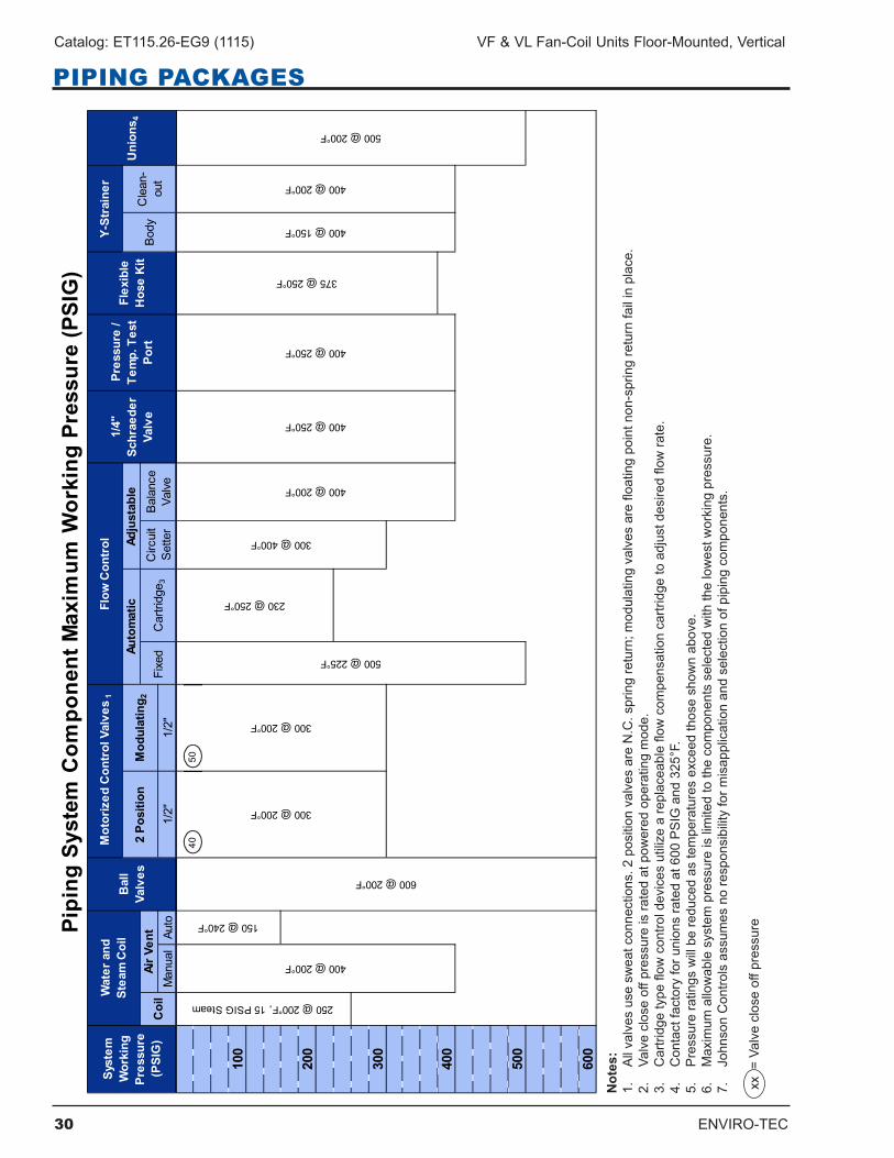
Pipi
ng S
yste
m C
ompo
nent
Max
imum
Wor
king
Pre
ssur
e (P
SIG
)Sy
stem
W
orki
ng
Pres
sure
(P
SIG
)
Wat
er a
nd
St
eam
Coi
lB
all
Valv
es
Mot
oriz
ed C
ontr
ol V
alve
s 1
Flow
Con
trol
Uni
ons 4
2 Po
sitio
nM
odul
atin
g 2Au
tom
atic
Adju
stab
leBo
dy
4050
Not
es:
1.Allvalvesusesw
eatconnections.2positionvalvesareN.C.springreturn;m
odulatingvalvesarefloatingpointnon-springreturnfailinplace.
2.Valvecloseoffpressureisratedatpow
eredoperatingmode.
3.Cartridgetypeflow
controldevicesutilizeareplaceableflowcom
pensationcartridgetoadjustdesiredflowrate.
4.Contactfactoryforunionsratedat600PSIGand325°F.
5.Pressureratingswillbereducedastemperaturesexceedthoseshow
nabove.
6.Maximum
allowablesystempressureislimitedtothecomponentsselectedwiththelowestw
orkingpressure.
7.JohnsonControlsassum
esnoresponsibilityform
isapplicationandselectionofpipingcomponents.
xx=Valvecloseoffpressure
ENVIRO-TEC 31
VF & VL Fan-Coil Units Floor-Mounted, Vertical Catalog: ET115.26-EG9 (1115)
PIPING PACKAGES
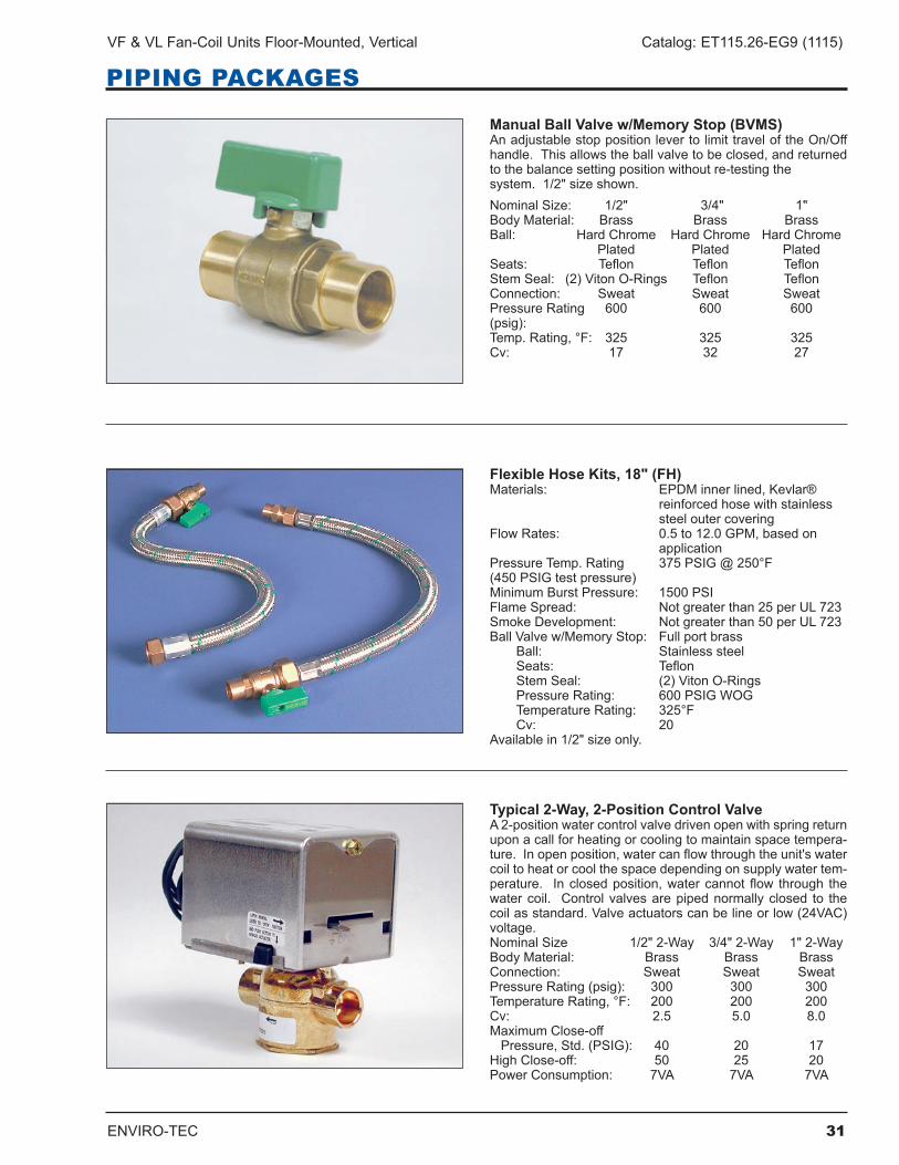
Manual Ball Valve w/Memory Stop (BVMS)AnadjustablestoppositionlevertolimittraveloftheOn/Offhandle.Thisallowstheballvalvetobeclosed,andreturnedtothebalancesettingpositionwithoutre-testingthesystem.1/2"sizeshown.NominalSize: 1/2" 3/4" 1"Body Material: Brass Brass BrassBall: Hard Chrome Hard Chrome Hard Chrome Plated Plated PlatedSeats: Teflon Teflon TeflonStemSeal: (2)VitonO-Rings Teflon TeflonConnection: Sweat Sweat SweatPressureRating 600 600 600(psig): Temp.Rating,°F: 325 325 325Cv: 17 32 27
Flexible Hose Kits, 18" (FH)Materials: EPDMinnerlined,Kevlar® reinforcedhosewithstainless steeloutercoveringFlowRates: 0.5to12.0GPM,basedon applicationPressureTemp.Rating 375PSIG@250°F(450PSIGtestpressure)MinimumBurstPressure: 1500PSIFlameSpread: Notgreaterthan25perUL723SmokeDevelopment: Notgreaterthan50perUL723BallValvew/MemoryStop: Fullportbrass Ball: Stainless steel Seats: Teflon Stem Seal: (2) Viton O-Rings PressureRating: 600PSIGWOG TemperatureRating: 325°F Cv: 20Availablein1/2"sizeonly.
Typical 2-Way, 2-Position Control ValveA2-positionwatercontrolvalvedrivenopenwithspringreturnupon a call for heating or cooling to maintain space tempera-ture.Inopenposition,watercanflowthroughtheunit'swatercoiltoheatorcoolthespacedependingonsupplywatertem-perature. Inclosedposition,watercannotflow through thewatercoil. Controlvalvesarepipednormallyclosed to thecoilasstandard.Valveactuatorscanbelineorlow(24VAC)voltage.NominalSize 1/2"2-Way 3/4"2-Way 1"2-WayBody Material: Brass Brass BrassConnection: Sweat Sweat SweatPressureRating(psig): 300 300 300TemperatureRating,°F: 200 200 200Cv: 2.5 5.0 8.0MaximumClose-offPressure,Std.(PSIG): 40 20 17HighClose-off: 50 25 20PowerConsumption: 7VA 7VA 7VA
32 ENVIRO-TEC
Catalog: ET115.26-EG9 (1115) VF & VL Fan-Coil Units Floor-Mounted, Vertical
PIPING PACKAGES
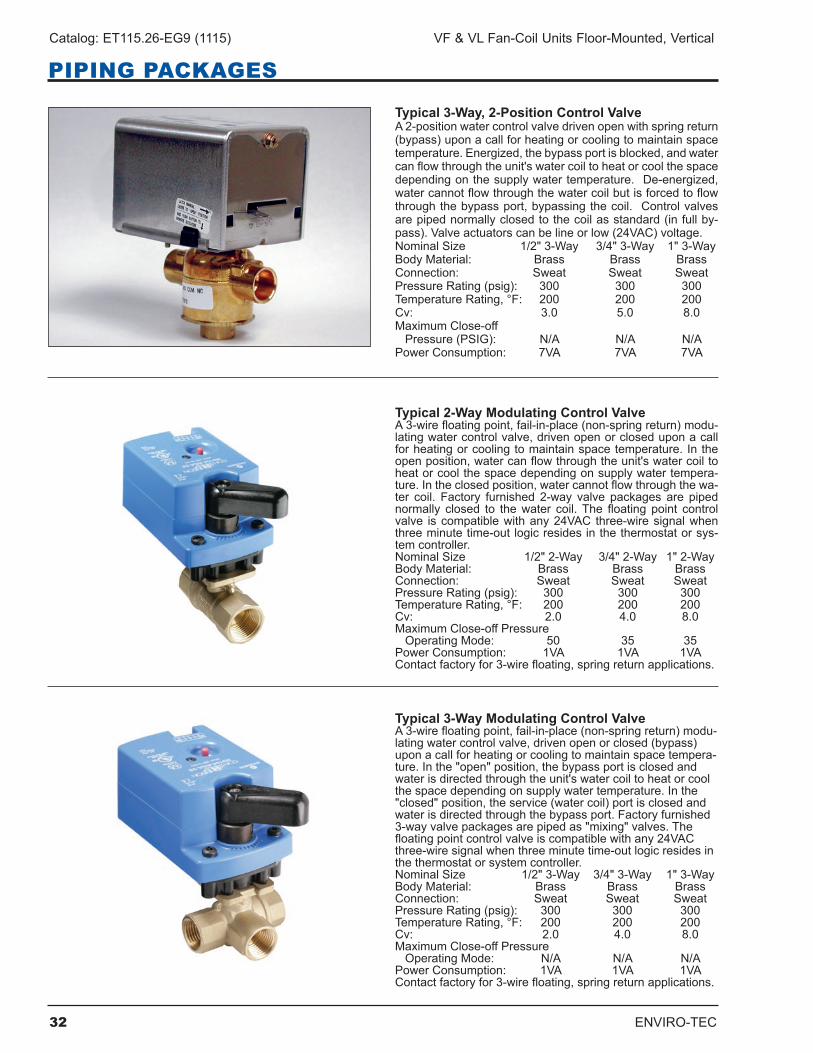
Typical 3-Way, 2-Position Control ValveA2-positionwatercontrolvalvedrivenopenwithspringreturn(bypass)uponacallforheatingorcoolingtomaintainspacetemperature.Energized,thebypassportisblocked,andwatercanflowthroughtheunit'swatercoiltoheatorcoolthespacedependingonthesupplywatertemperature.De-energized,watercannotflowthroughthewatercoilbutisforcedtoflowthroughthebypassport,bypassingthecoil. Controlvalvesarepipednormallyclosedtothecoilasstandard(infullby-pass).Valveactuatorscanbelineorlow(24VAC)voltage.NominalSize 1/2"3-Way 3/4"3-Way 1"3-WayBody Material: Brass Brass BrassConnection: Sweat Sweat SweatPressureRating(psig): 300 300 300TemperatureRating,°F: 200 200 200Cv: 3.0 5.0 8.0MaximumClose-offPressure(PSIG): N/A N/A N/APowerConsumption: 7VA 7VA 7VA
Typical 2-Way Modulating Control ValveA3-wirefloatingpoint,fail-in-place(non-springreturn)modu-latingwatercontrolvalve,drivenopenorcloseduponacallfor heating or cooling to maintain space temperature . In the openposition,watercanflowthroughtheunit'swatercoiltoheatorcoolthespacedependingonsupplywatertempera-ture.Intheclosedposition,watercannotflowthroughthewa-ter coil. Factory furnished 2-way valve packages are pipednormally closed to thewater coil.The floating point controlvalve iscompatiblewithany24VAC three-wiresignalwhenthree minute time-out logic resides in the thermostat or sys-tem controller .NominalSize 1/2"2-Way 3/4"2-Way 1"2-WayBody Material: Brass Brass BrassConnection: Sweat Sweat SweatPressureRating(psig): 300 300 300TemperatureRating,°F: 200 200 200Cv: 2.0 4.0 8.0MaximumClose-offPressureOperatingMode: 50 35 35PowerConsumption: 1VA 1VA 1VAContactfactoryfor3-wirefloating,springreturnapplications.
Typical 3-Way Modulating Control ValveA3-wirefloatingpoint,fail-in-place(non-springreturn)modu-latingwatercontrolvalve,drivenopenorclosed(bypass)upon a call for heating or cooling to maintain space tempera-ture.Inthe"open"position,thebypassportisclosedandwaterisdirectedthroughtheunit'swatercoiltoheatorcoolthespacedependingonsupplywatertemperature.Inthe"closed"position,theservice(watercoil)portisclosedandwaterisdirectedthroughthebypassport.Factoryfurnished3-wayvalvepackagesarepipedas"mixing"valves.Thefloatingpointcontrolvalveiscompatiblewithany24VACthree-wiresignalwhenthreeminutetime-outlogicresidesinthe thermostat or system controller .NominalSize 1/2"3-Way 3/4"3-Way 1"3-WayBody Material: Brass Brass BrassConnection: Sweat Sweat SweatPressureRating(psig): 300 300 300TemperatureRating,°F: 200 200 200Cv: 2.0 4.0 8.0MaximumClose-offPressureOperatingMode: N/A N/A N/APowerConsumption: 1VA 1VA 1VAContactfactoryfor3-wirefloating,springreturnapplications.
ENVIRO-TEC 33
VF & VL Fan-Coil Units Floor-Mounted, Vertical Catalog: ET115.26-EG9 (1115)
PIPING PACKAGES
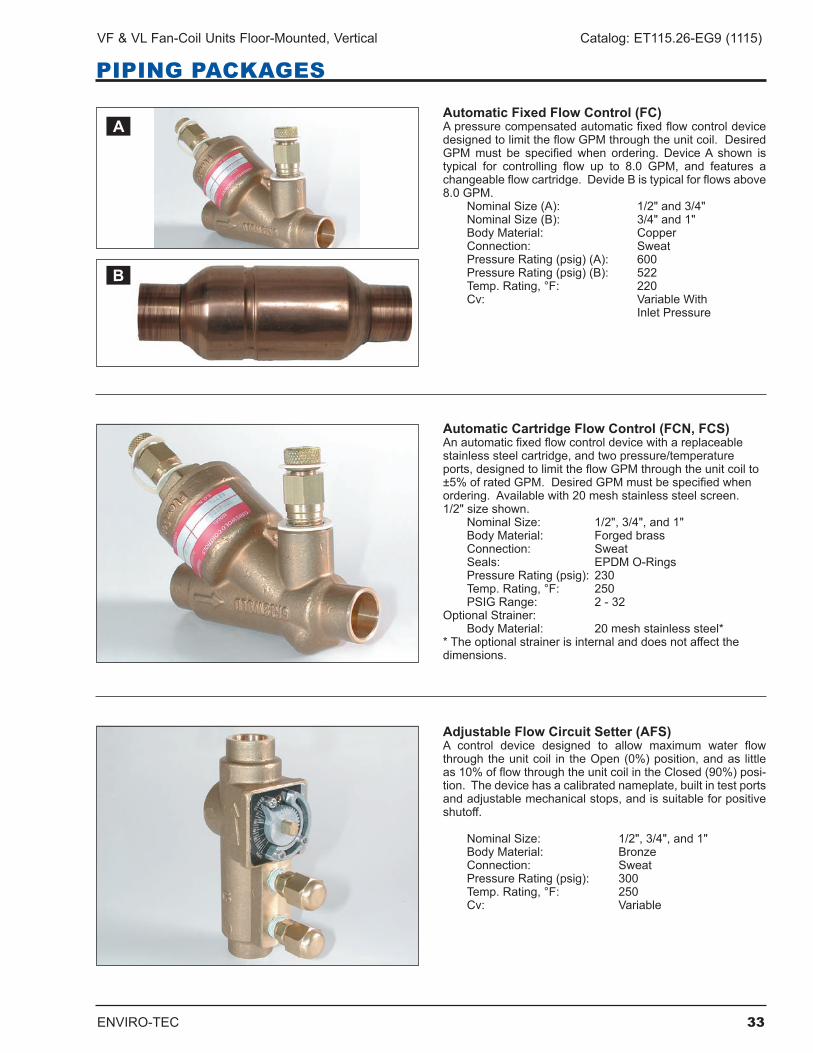
Automatic Fixed Flow Control (FC)ApressurecompensatedautomaticfixedflowcontroldevicedesignedtolimittheflowGPMthroughtheunitcoil.DesiredGPMmust be specifiedwhen ordering. DeviceA shown istypical for controlling flow up to 8.0 GPM, and features achangeableflowcartridge.DevideBistypicalforflowsabove8.0GPM. NominalSize(A): 1/2"and3/4" NominalSize(B): 3/4"and1" Body Material: Copper Connection: Sweat PressureRating(psig)(A): 600 Pressure Rating (psig) (B): 522 Temp.Rating,°F: 220 Cv: VariableWith Inlet Pressure
Automatic Cartridge Flow Control (FCN, FCS)Anautomaticfixedflowcontroldevicewithareplaceablestainlesssteelcartridge,andtwopressure/temperatureports,designedtolimittheflowGPMthroughtheunitcoilto±5%ofratedGPM.DesiredGPMmustbespecifiedwhenordering.Availablewith20meshstainlesssteelscreen.1/2"sizeshown. NominalSize: 1/2",3/4",and1" BodyMaterial: Forgedbrass Connection: Sweat Seals: EPDM O-Rings PressureRating(psig): 230 Temp.Rating,°F: 250 PSIG Range: 2 - 32Optional Strainer: BodyMaterial: 20meshstainlesssteel**Theoptionalstrainerisinternalanddoesnotaffectthedimensions .
Adjustable Flow Circuit Setter (AFS)A control device designed to allow maximum water flowthroughtheunitcoil in theOpen(0%)position,andas littleas10%offlowthroughtheunitcoilintheClosed(90%)posi-tion.Thedevicehasacalibratednameplate,builtintestportsandadjustablemechanicalstops,andissuitableforpositiveshutoff.
NominalSize: 1/2",3/4",and1" Body Material: Bronze Connection: Sweat PressureRating(psig): 300 Temp.Rating,°F: 250 Cv: Variable
A
B
34 ENVIRO-TEC
Catalog: ET115.26-EG9 (1115) VF & VL Fan-Coil Units Floor-Mounted, Vertical
PIPING PACKAGES
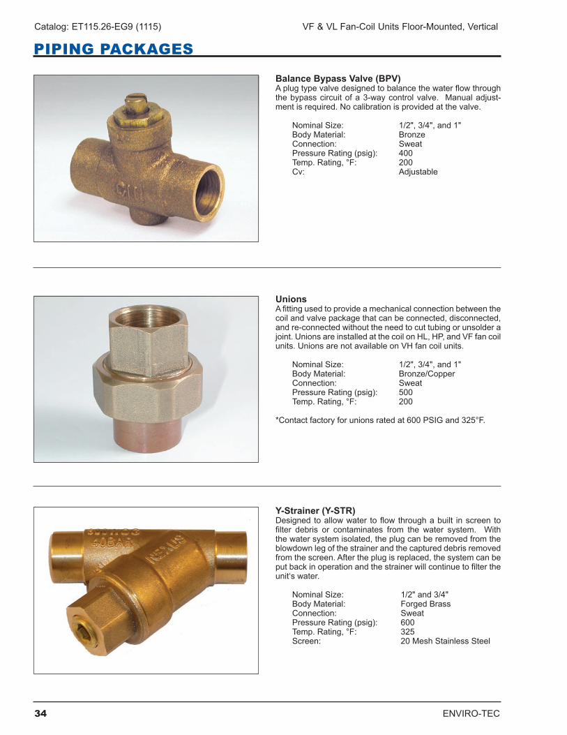
Balance Bypass Valve (BPV)Aplugtypevalvedesignedtobalancethewaterflowthroughthebypasscircuitofa3-waycontrolvalve. Manualadjust-mentisrequired.Nocalibrationisprovidedatthevalve.
NominalSize: 1/2",3/4",and1" Body Material: Bronze Connection: Sweat PressureRating(psig): 400 Temp.Rating,°F: 200 Cv: Adjustable
UnionsAfittingusedtoprovideamechanicalconnectionbetweenthecoilandvalvepackagethatcanbeconnected,disconnected,andre-connectedwithouttheneedtocuttubingorunsolderajoint.UnionsareinstalledatthecoilonHL,HP,andVFfancoilunits.UnionsarenotavailableonVHfancoilunits.
NominalSize: 1/2",3/4",and1" BodyMaterial: Bronze/Copper Connection: Sweat PressureRating(psig): 500 Temp.Rating,°F: 200
*Contactfactoryforunionsratedat600PSIGand325°F.
Y-Strainer (Y-STR)Designed toallowwater toflowthroughabuilt inscreen tofilter debris or contaminates from the water system. Withthewatersystemisolated,theplugcanberemovedfromtheblowdownlegofthestrainerandthecaptureddebrisremovedfromthescreen.Aftertheplugisreplaced,thesystemcanbeputbackinoperationandthestrainerwillcontinuetofiltertheunit‘swater.
NominalSize: 1/2"and3/4" Body Material: Forged Brass Connection: Sweat PressureRating(psig): 600 Temp.Rating,°F: 325 Screen: 20MeshStainlessSteel
ENVIRO-TEC 35
VF & VL Fan-Coil Units Floor-Mounted, Vertical Catalog: ET115.26-EG9 (1115)
PIPING PACKAGES
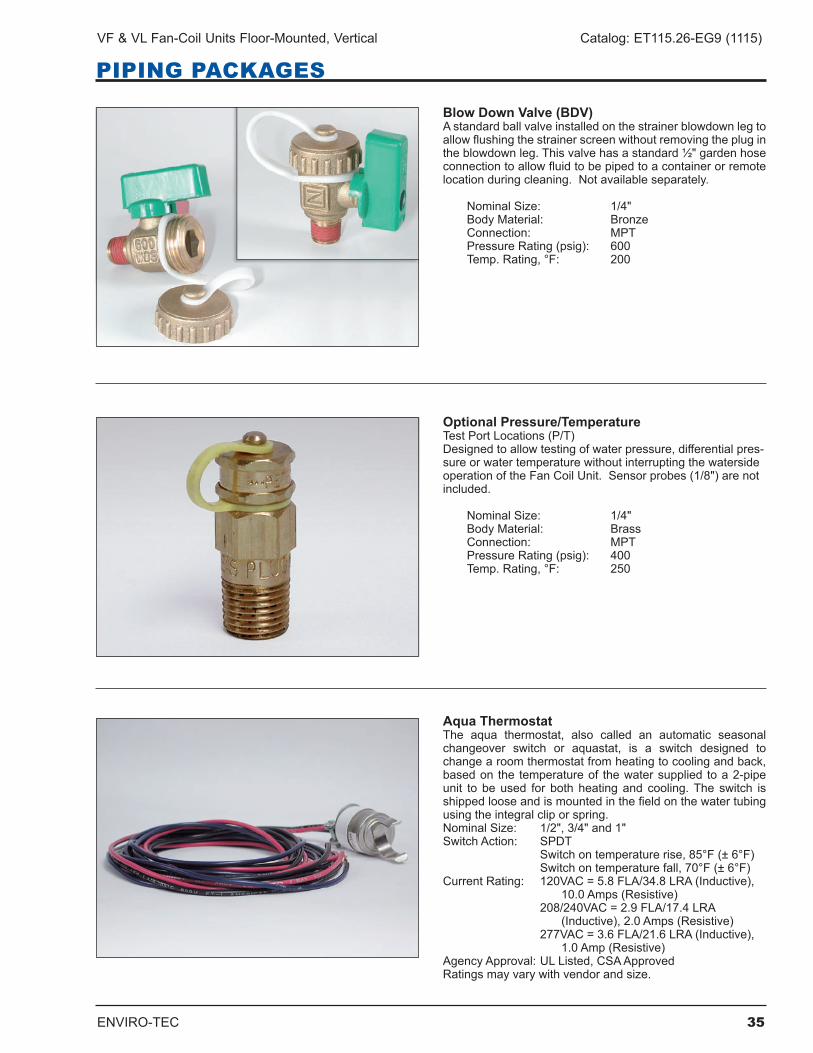
Blow Down Valve (BDV)Astandardballvalveinstalledonthestrainerblowdownlegtoallowflushingthestrainerscreenwithoutremovingtheplugintheblowdownleg.Thisvalvehasastandard½"gardenhoseconnectiontoallowfluidtobepipedtoacontainerorremotelocationduringcleaning.Notavailableseparately.
NominalSize: 1/4" Body Material: Bronze Connection: MPT PressureRating(psig): 600 Temp.Rating,°F: 200
Optional Pressure/Temperature TestPortLocations(P/T)Designedtoallowtestingofwaterpressure,differentialpres-sureorwatertemperaturewithoutinterruptingthewatersideoperationoftheFanCoilUnit.Sensorprobes(1/8")arenotincluded .
NominalSize: 1/4" Body Material: Brass Connection: MPT PressureRating(psig): 400 Temp.Rating,°F: 250
Aqua ThermostatThe aqua thermostat, also called an automatic seasonalchangeover switch or aquastat, is a switch designed tochangearoomthermostatfromheatingtocoolingandback,basedon the temperatureof thewatersupplied toa2-pipeunit to beused for bothheatingand cooling.The switch isshippedlooseandismountedinthefieldonthewatertubingusing the integral clip or spring .NominalSize: 1/2",3/4"and1"SwitchAction: SPDT Switchontemperaturerise,85°F(±6°F) Switchontemperaturefall,70°F(±6°F)CurrentRating: 120VAC=5.8FLA/34.8LRA(Inductive), 10.0Amps(Resistive) 208/240VAC=2.9FLA/17.4LRA (Inductive),2.0Amps(Resistive) 277VAC=3.6FLA/21.6LRA(Inductive), 1.0Amp(Resistive)AgencyApproval:ULListed,CSAApprovedRatingsmayvarywithvendorandsize.
36 ENVIRO-TEC
Catalog: ET115.26-EG9 (1115) VF & VL Fan-Coil Units Floor-Mounted, Vertical
GUIDE SPECIFICATIONS: VF AND VL SERIES
GENERALFurnish and install ENVIRO-TEC Vertical Floor Direct DriveFanCoilUnitswhereindicatedontheplansandinthespecifications.Allunitsshallbecapableofmeet-ingorexceedingthescheduledcapacitiesforcooling,heating and air delivery. Units shall be ETL listed incompliancewithUL/ANSIStandard1995,andbecerti-fiedascomplyingwithAHRIStandard440-2008.
CONSTRUCTIONAllunitchassisshallbefabricatedofheavygaugegal-vanized steel panels.All unit chassis panels shall beinsulatedwithElastomericClosedCellFoamInsulation.InsulationshallconformtoUL181forerosionandNFPA90Aforfire,smokeandmelting,andcomplywitha25/50FlameSpreadandSmokeDevelopedIndexperASTME-84 orUL 723. Additionally, insulation shall complywithAntimicrobialPerformanceRatingof0,noobservedgrowth, perASTMG-21. Polyethylene or Fiberglassinsulationisnotacceptable.
Allexposedunitsshallhaveexteriorpanelsfabricatedofnotlessthan20gaugegalvannealedsteel[Providea 16 gauge front panel on exposed units]. The frontpanel shall be attached with quarter turn quick openfastenerstoallowforeasyremovalandaccessforser-vice.[Thefrontpanelshallbeattachedwithtamperprooffasteners.Sidepanelsshallberemovableforaccesstocontrolsandpipingwithintheendpockets].
Toppanelshallberemovablefromfancoilwithouttheneedtodisconnectpipingorelectricalwiring(VFE/VFS).Thetoppanelshallberemovedthroughnotmorethan8screws.
Provide a grille in the return air opening (VLE only).[Provideagrilleinthereturnairopening.(VFE,VFS).][Provideadecorativereturnairopening(VFC).]
All exposed units shall include a recessed stampedlouverdischargegrille.Louverdischargegrilleshallbereversestamped(VFSonly).[Provideanarchitecturalgradelinearbardischargegrillewithapowdercoatedpaint finish tomatch cabinet color. Liquid coat paintshallnotbeacceptable.]
Allconcealedunitsshallhaveaminimum1"ductcollaron the discharge .
PAINTED FINISHAllpaintedcabinetexteriorpanelsshallbefinishedwithaheatcuredanodicacrylicpowderpaintofthestandardfactory color. Liquid coat paint shall not be accept-able.
SOUNDUnits shall have published sound power level datatestedinaccordancewithAHRIStandard350.
POWERUnitsshallnotexceedscheduledpowerconsumption.
FAN & MOTOR Unitfanshallbedynamicallybalanced,forwardcurved,DWDIcentrifugal typeconstructedofgalvanizedsteelforcorrosionresistance.Motorsshallbehighefficiency,permanentlylubricatedsleevebearing,permanentsplit-capacitortypewithULandCSAlistedautomaticresetthermaloverloadprotectionandthreeseparatehorse-power taps. Shaded polemotors are not acceptable.Singlespeedmotorsarenotacceptable.
Thefan/motorassemblyshallberemovableandservice-ablethroughthefrontpanel.Eachfan/motorassemblyshallbefastenedbynomorethan2screws.Thefan/motorassemblyshallbenolongerthan44”,andshallbeeasilyremovablebyasingleservicetechnician.Themotorsshallhavequickconnectorstoallowserviceandremovalwithouttheneedfortools.
DRAIN PAN Primary condensate drain pans shall be single wall,heavygaugegalvanizedsteelforcorrosionresistance,and extend under the entire coil section . Drain pans shall beofonepiececonstructionandbedoubleslopedforcondensate removal. Drainpanaccess that requiresremovalofcoilsisnotacceptable.
Theprimarydrainpanshallbeexternallyinsulatedwithafireretardant,elastomericclosedcellfoaminsulation.Theinsulationshallcarrynomorethana25/50FlameSpreadandSmokeDevelopedRatingperASTME-84andUL723andanAntimicrobialPerformanceRatingof0,noobservedgrowth,perASTMG-21.Doublewallnon-corrosiveauxiliarydrainpanisusedforcondensatefromprimarydrainpanandoptionalvalvepackages.
Option:Provideaprimarydrainpanconstructedentire-lyofheavygaugestainlesssteelforsuperiorcorrosionresistance .
COILSAllcoolingandheatingcoilsshalloptimizerowstomeetthespecifiedcapacity.Coilsshallhaveseamlesscoppertubesandshallbemechanicallyexpanded toprovideanefficient,permanentbondbetweenthetubeandfin. Finsshallhavehighefficiencyaluminum[copper]sur-faceoptimizedforheattransfer,airpressuredropandcarryover.Lancedfinsshallnotbeacceptable.
ENVIRO-TEC 37
VF & VL Fan-Coil Units Floor-Mounted, Vertical Catalog: ET115.26-EG9 (1115)
GUIDE SPECIFICATIONS: VF AND VL SERIES
Allcoilsshallbetestedat325PSIGairpressureunderwater, and rated for a maximum 300 PSIG workingpressureat200°F.
All water coils shall be designed to connect with½”nominal pipe connections .
CoilCasingshallbe fabricated fromgalvanizedsteel[stainlesssteel].
Heating coils shall be furnished in the pre-heat (VFOnly) or re-heat position .
Directexpansioncoolingcoilsshallbefactorysealedandchargedwithminimum25PSIGnitrogenorrefrig-erated dry air .
Steamcoilsshallbestandardsingletubesteamtypesuitable for temperatures above 35°F and 15 PSIGsteam pressure .
Allwatercoilsshallbeprovidedwithamanualairventfittingtoallowforcoilventing.
FILTERSAllunitsshallbefurnishedwithaminimum1"nominalglassfiberthrowaway(1”pleatedMERV7)(1”pleatedMERV8) (1”pleatedMERV13) filter.Filtersshallbetightfittingtopreventairbypass.Filtersshallbeeasilyremovablefromthereturnairopeningwithouttheneedfor tools (VF Only) .
ELECTRICALUnitsshallbefurnishedwithsinglepointpowerconnec-tion.Provideanelectrical junctionboxformotorandother electrical terminations .
Option: Provide 24VAC fan relay boardwith 25VAtransformer. Fan relayboarddesigned tooperate inconjunctionwithfactoryprovided(fieldprovided)24Vthermostat.Fanrelayboarddesignedtoaccept115,208,220,230,or277Vinputpower.Fanrelayboardtobefactoryinstalled.
Relay board shall operate with generic thermostatdesigned to control up to three independently energized fan speeds .
ELECTRIC HEATFurnishanelectricresistanceheatingassemblyasanintegralpartofthefancoilunit,withtheheatingcapac-ity, voltage and kilowatts scheduled. The heaterassemblyshallberatedforinstallationonthefancoilunitandbelocatedsoasnottoexposethefanassem-bly to excessive leaving air temperatures that couldaffect motor performance .
Theheaterandunitassemblyshallbe listedforzeroclearanceandmeetallNECrequirements,andbeETLlistedwiththeunitasanassemblyincompliancewithUL/ANSIStandard1995.
All heating elements on floormounted units shall befinnedtubulartype.Elementsshallbeconstructedofnickelchromiumresistancewirecenteredintubesandembedded in refractory material. Terminals shall besealedwithsiliconerubbertoprotectagainstmoisture.Terminalsandhardwareshallbestainlesssteelforcor-rosionresistance.All internalwiringshallberatedfor105°Cminimum.
All heaters shall include over temperature protectionconsisting of an automatic reset primary thermal limit andback-upsecondarythermallimit.Allheatersshallbesinglestage.
Option: Devices used to energize and de-energize(switch)electricheatmustbe totallysilent.Magnetic,mercury,and/orquietrelaysand/orcontactorsarenotacceptable.
PIPING PACKAGESProvide a standard factory assembled valve pipingpackage toconsistofa2or3-way,on/off,motorizedelectriccontrolvalveandtwoballisolationvalves.
Controlvalvesshallbepipednormallyclosedtothecoil.Control valves shall bewired to relay board throughquick connects to allow service and replacement ofvalves.Quickconnectsshallprevent incorrectwiringthroughphysicalandcolorcodedvisualconfirmation.Maximum entering water temperature on the controlvalveshallbe200°F,andmaximumoperatingpressureshallbe300PSIG.
Unions shall be provided to allow removal of pipingpackagefromunitwithouttheneedforbrazingorcuttingpipe .
Option:Provide3-wirefloatingpointmodulatingcontrolvalve(fail-in-place),inlieuofstandard2-positioncontrolvalvewithfactoryassembledvalvepipingpackage.
Option: Provide high pressure close-off actuator for2-wayon/offcontrolvalve.Maximumclose-offpressureis50PSIG(1/2"),25PSIG(3/4)",or20PSIG(1”).
Option:Provideeitherafixedoradjustableflowcontroldeviceforeachpipingpackage.Option:Providepressure-temperatureports (P/T) foreachpipingpackagetoallowmeasurementacrossthecoil .
38 ENVIRO-TEC
Catalog: ET115.26-EG9 (1115) VF & VL Fan-Coil Units Floor-Mounted, Vertical
GUIDE SPECIFICATIONS: VF AND VL SERIES
Pipingpackagesshallbecompletelyfactoryassembled,including interconnecting pipe and shipped loose for field installation .
Option: Piping package will be shipped factoryinstalled .
OUTSIDE AIR DAMPER (VF Only)Provideamanualortwopositionmotorizedoutsideairdamper integral to the unit .
Option:Providealuminumoutsideairwallbox(VFOnly)with integral insect screen and weep holes for fieldinstallation .

ENVIRO-TEC 39
VF & VL Fan-Coil Units Floor-Mounted, Vertical Catalog: ET115.26-EG9 (1115)

ENVIRO-TECisaregisteredtrademarkofJohnsonControls,Inc.intheUnitedStatesofAmericaandothercountries. Othertrademarksusedhereinmaybetrademarksorregisteredtrademarksofothercompanies.
Catalog: ET115 .26-EG9 (1115) Supersedes ET115 .26-EG9 (915)©2015JohnsonControls,Inc.P.O.Box423,Milwaukee,WI53201PrintedinUSAwww.enviro-tec.com


![SECCIONES - pressfolios-production.s3.amazonaws.com · [ 4 ] CAPITAL RIESGO 2013 OPERACIONES VF: Mediobanca / KPMG VL: Uría Menéndez CF: Arcano Corporate / Deloitte CL: Garrigues](https://img.pdfslide.net/doc/110x75/5bb6d70e09d3f20c668cc019/secciones-pressfolios-productions3-4-capital-riesgo-2013-operaciones.jpg)