Embed Size (px)
Citation preview

GOVERNMENT OF INDIAMINISTRY OF RAILWAYS
~?imCif ~ lJCi JiI6f.cp l':ldld6f.
m <Ji~
RESEARCH DESIGNS AND STANDARDS ORGANISATIONMINISTRY OF RAILWAYS
cP ftt. ~ Vfl~ cj} ftffc! cpCfS~c:.vuueft ctft ftlfirtJc
SPECIFICATION OF CONDUIT SYSTEM FOR CABLEMANAGEMENT
Spec No. RDSO/PE/SPEC/AC-0138- 2009 (Rev. 1)3fR.t!t.rm:.m1./Tft.t./rm: Tft t ~/l!.~./ 0138 (Hm.l)-2009
S. No. Date Revision Reason1 March-2012 1 Sizes of conduits and fittings added.
APPROVED fl.JJ o.S\~~04.tY
CPI~lCPItl t6f:C:~fCP/ Tft rm: l!US t lTc1l ~ED/PS&EMU
~ . Checked BySSE/Design/Elec~ 0"> , 1 fl.-.-

Clause No.1.02.03.04.05.06.06.46.57.08.09.010.011.012.013.0
Pa e No.3334467810101112121213

I Page 3 of 23
Presently, the flexible conduits used in wiring of cables are as per IS: 9537.Mostly PVCconduit & fittings are used. However, in LHB coaches Polyamide conduits are being used.To standardize the specification for halogen free, fire retardant conduit for rolling stockapplication, this specification is prepared.
1.1 This specification covers performance parameters, general & technical requirements,method of sampling, inspection, testing and supply of conduits and its fittings.
1.2 The conduit system of cable management shall comprise polyamide flexible conduit andend fittings with threaded ends (both metric and Pg thread) provided with gaskets, a-ringsand metallic lock nuts ensuring minimum IP-67 protection of the system.
1.3 Any deviation from this specification proposed by the manufacturer, aimed to improve uponthe performance, utility and reliability /efficiency of the equipment will be given dueconsideration, provided full particulars of the deviations with justification are furnished toROSa. In such a case, the proposed product must be proven in rolling stock application intropical countries for at least five years. The manufacturer shall submit full technical detail ofthe proposed product along with the test report from reputed national/internationallaboratory for evaluation to ROSa. In case of any contradiction between the provisions ofIS/IEC and this specification, the later shall prevail.
Manufacturers of this item shall get ROSa approval for their product for which theguidelines can be obtained from website www.rdso.gov.in. Such manufacturers shall haveinfrastructure for manufacture, testing and supply of conduits and its fittings as perrequirements specified in this specification. The conduit and its accessories shall beapproved in a set.
Purchaser shall specify the size of conduit and its accessories as per their requirementconfirming to this specification. However, sizes normally used by RCF is as per Annexure-A.It should be noted that the conduits and its fittings shall be of same make only.
SpecificationslStandardsIEC- 61386-1
~SSt!Desig'iVElect
I RDSO/PE/SPEC/0138-2009(Rev-1)
Conduits system for cable management (Flexible conduitss stem.Railway applications-Rolling stock equipment-shock andvibration testsClassification of degrees of protection provided by enclosuresof e ui ment.Fire. smoke & toxicit re uirementsConduit system of cable management (Threads for Metric EndFittin s & lock NutsThreads for PG End Fittin s
NFF 16-101 &102IEC-60423
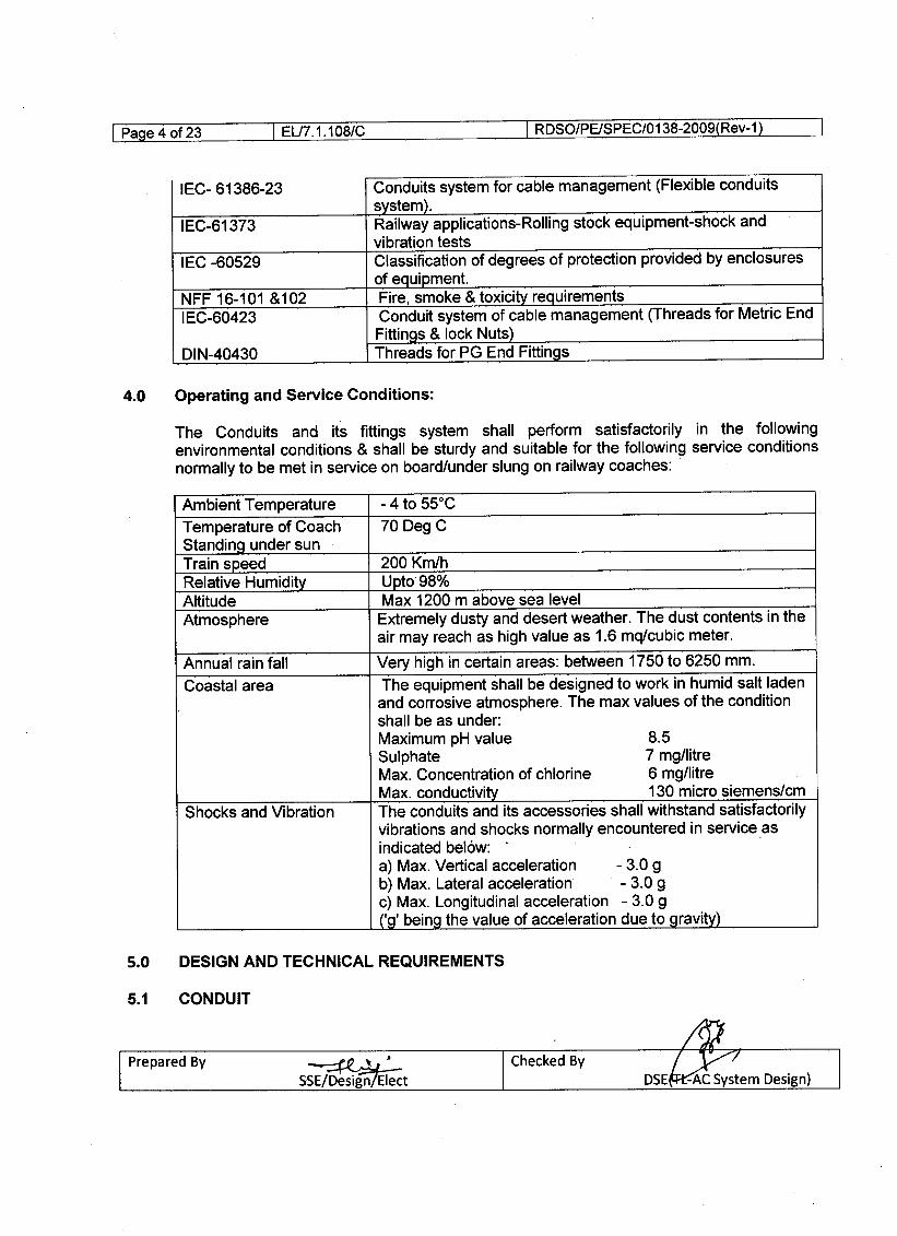
The Conduits and its fittings system shall perform satisfactorily in the followingenvironmental conditions & shall be sturdy and suitable for the following service conditionsnormally to be met in service on board/under slung on railway coaches:
Ambient Temperature - 4 to 55°CTemperature of Coach 70 Deg CStanding under sunTrain speed 200 Km/hRelative Humidity Upto98%Altitude Max 1200 m above sea levelAtmosphere Extremely dusty and desert weather. The dust contents in the
air may reach as high value as 1.6 mq/cubic meter.
Annual rain fall Very high in certain areas: between 1750 to 6250 mm.Coastal area The equipment shall be designed to work in humid salt laden
and corrosive atmosphere. The max values of the conditionshall be as under:Maximum pH value 8.5Sulphate 7 mgllitreMax. Concentration of chlorine 6 mgllitreMax. conductivity 130 micro siemens/em
Shocks and Vibration The conduits and its accessories shall withstand satisfactorilyvibrations and shocks normally encountered in service .asindicated below:a) Max. Vertical acceleration - 3.0 gb) Max. Lateral acceleration - 3.0 gc) Max. Longitudinal acceleration - 3.0 g('g' being the value of acceleration due to gravity)
~SSE/Design/Elect

I EU7. 1. 1DBle
The Conduit system for cable management shall comprise of mainly conduit, end fittings,lock nuts, terminal sleeve etc. The material for the conduit and its accessories shall bepolyamide -6 (PA-6). It should be free from halogen, phosphorous, sulphur and cadmium. Itshould be UV resistant and resistant to abrasion and corrosive environment.
5.1.2 There shall be no sharp edges, burrs or surface projections which are likely to damageinsulated conductors or cables or inflict Injury to the user or installer.
5.1.3 The conduits shall have coarse profile with internal and external corrugation, thick walledmedium duty generally confirming to IEC-61386 for sizes NW17 & above (as per Annexure-A), however the sizes below NW17 shall be of light classification confirming to IEC-61386.
5.1.4 The conduit and conduit fittings shall withstand the stresses likely to occur during transportstorage etc.
5.1.5 The colour of the conduits and accessories shall be black, unless otherwise specified.5.1.6 Flexible conduit shall be suitable for provision in the under carriage of Railways with high
impact strength suitable for working in service conditions as per clause 4.0. It should havefollowing properties:-
a) Conduit shall be internally and externally corrugated.b) Conduit should as per classification "medium" for resistant to compression, tensile strength
and suspended load capacity as per IEC-61386-1 for size NW 17 and above. Size belowNW 17 shall be "light" classification as per IEC 61386.
c) Conduit should be non-flame propagating as defined in IEC- 61386-1.d) The conduit shall be suitable for category A-2 application as per Para 5.1 of NFF 16-101.f) Its self extinguishing class shall be 13as per NFF 16-101. .g) Its smoke emission classification shall be F3 as per NFF 16- 101.h) Its oxygen index shall be greater than 25%, when tested as per ISO 4589.i) It should be suitable for continuous temperature range -:1O°C to +105 °C.
5.1.7 Conduit shall havedi-electric strength and insulation resistance as per Para 11.3 of IEC-61386-1.
5.1.8 The complete cable protection system shall be suitable for minimum IP-67 as per IEC-60529 for its connection.
5.1.9 The conduit shall be circular in section with concentricity of more than 90%. Theconcentricity shall be calculated as the ratio of the maximum and minimum thicknessmeasured on the same cross section on the opposite sides.
~J_
SSE!Design1EleCt

I RDSO/PEISPEC/0138-2009(Rev-1)
The end fittings are the connectors provided at the ends of the flexible conduits at each endwhich in turn terminates in the equipment I sub-assembly used for outdoor application. Theconnection to the flexible conduit shall be such as not to become loose due to vibrationsencountered in rolling stock. This shall include the end fittings and accessories such as y-connector (for taking out two outputs from one).
For connection of flexible conduit with end fitting, system shall be such as the conduit isfitted with push in or safety lock retaining ring type arrangement to be inserted for fixing theconduit. Incidental dismantling or reduction in sealing performance shall not be permitted.
Threading provided at the end of the end fitting shall be as per the interface. If the interfaceis plastic then the threads & hexagonal locknuts shall be of Polyamide - 6 material and ifthe interface is metal then threads & hexagonal locknuts shall be of Nickel plated brasshowever the entire metal thread length shall be internally insulated with Polyamide - 6Material. The thread design shall be as per the requirements for PG Threads confirming toDIN-40430 & Metric Threads confirming to IEC-60423 respectively. The minimum threadlength shall be 10 mm for the various sizes & types of end fittings.
To maintain the IP-67 level the fitting shall be provided with Gaskets & O-ring to avoid wateringress. The material of O-ring shall be NBR however the gaskets shall be Non AsbestosReinforced NBR.
The fitting shall be provided with a metallic thread (insert part) to guarantee a secure andvibrations free fitting and the connection partner. No metallic part shall however have directcontact with cables traversing through it
The tube clamps are required for holding the conduits in place. The tube clamps should bemade from Galvanized Steel and to be covered with Elastomeric profile for better grip & toavoid damage to conduits. Elastomeric material should be self-extinguishing & free fromhalogens, phosphorous and cadmium. The application temp range should be -40 Deg C to+105 Deg C. Ends of the Tube clamps to be provided with holes to install the fixing screws
These are cylindrical sleeves for conduit termination and are used at the end of the conduitswhere no connector with threads are necessary and to avoid the damage of cable isolationsthrough sharp cutting edges on the conduit. .
~~~SSE/Desi'gn/~

I EU7. 1. 1DB/e
These lock nuts are to be used in conjunction with end fittings suitable for both metric andPg thread. The material shall be brass nickel plated.
5.2.5 In-Line Connectors - These fittings are used to connect two corrugated conduit lengths ofthe same size (NW). Both the ends of these connectors shall be provided with the interfaceto fix the conduits. It shall be of Polyamide - 6 material.
5.2.6 Spouts - 2-Way & 4-Way Spouts shall be used for the distribution of cables in the roofwiring of the coaches. It shall be of Polyamide - 6 material.
5.2.7 Corrugated Conduits to Pipe Connector - The connectors shall be used to connect thecorrugated conduits to the Steel pipes carrying electrical wires.
5.2.8 Flange Connectors - Flanged connectors (Straight and Elbow) shall be used to connect theinterface of ZS coupling (In LHB Type coaches). The interface of the fittings should be ableto accommodate NW70 and NW95 size conduits. It shall be of Polyamide - 6 material.
5.2.9 Plug Screws - Plug screws are used to block the female threaded interface whereverrequired. It shall be of Polyamide-6 material for Plastic interface and Nickel plated brass forMetal interface.
6.1.1 Only after the detail drawings and the design have been approved and the clearance givento this effect, the manufacturer shall take up the manufacture of the prototype. It is to beclearly understood that any changes, required to be done in the prototype or any additionaltests other than specified herein are required to be conducted on the prototype unit or itscomponents, it shall be done expeditiously. During the process of manufacture of theequipment, if the purchaser so desires, may conduct/repeat any of the routine or additionaltests to satisfy himself that the quality of the model being manufactured is of the requiredstandards.
6.1.2 Subject to agreement between user and manufacturer, ROSOl purchaser shall repeat someor all type tests once in three years on sample basis, so as to confirm the quality of theproduct to meet the specified requirements.
6.1.3 The type tests shall be carried out by ROSa representative on prototype unit either totallyor in part under the following conditions without any additional cost:
• A manufacturer undertakes to manufacture for the first time as per this specification.• An important change in design details of product has been introduced.• Specification is modified necessitating re-designing of product.
" 'SSE/~

• Unsatisfactory performance reported from user Railways.• Resumption of production after an interruption of more than two years.
6.1.4 ROSa may conduct surprise check on manufacturing process and quality control alongwith ~ny of the tests to ensure quality of product and its conformance to ROSa
6.1.5 The tests shall be carried out at the works of the manufacturer or a reputed testinglaboratory in presence of Indian Railway representative on the prototype test sample of theconduits and its accessories as per relevant governing specifications modified or amplified.The manufacture shall have necessary arrangement for testing of conduits and its fittings.
6.1.7 The test protocol indicating relevant clause of the test, condition of the test, specified valueand observed value of the parameter for conduits shall be submitted by the firm beforeoffering the sample for testing.
6.2 Routine test:
Routine tests are to be carried out on each unit to verify that properties & design of theproduct corresponds to those measured during type test. Proper documentation of routinetests results shall be made available with the firm and will be produced before inspectingofficial on demand.
Each offered lot of supply shall be subjected to acceptance tests as per ROSa approvedsampling plan or as per sampling plan specified in IS 2501, at manufacturer's works.Acceptance test shall be witnessed by inspecting official nominated by purchaser/ROSa.Manufacturer on demand by inspecting official shall produce the internal/routine test reportcarried out by manufacturer.
S.No Description of test Clause No. Type Acceptance RoutineTest Test Test
1 Checking of IEC 61386-1 Yes Yes Yesdimension
2 Compression test IEC 61386-1 Yes Yes Yes3 Impact test IEC 61386-1 Yes Yes Yes4 Flexing test IEC 61386-23 Yes Yes Yes5 Tensile Test IEC 61386-1 Yes Yes No
&236 Suspended Load test IEC 61386-1 Yes No No7 Thermal Properties IEC 61386-1 Yes Yes No
&238 Oi-Electric Strength & IEC 61386-1 Yes Yes No
Insulation resistance r-.-.I n.,lI Prepared By
, ' I Checked ByDSE(TL-AC/J~n) ISSE/~

I EL/7.1.108/C I RDSO/PEISPEC/0138-2009(Rev-1)
test
9 Spread of fire IEC 61386-1 Yes Yes No10 Degree of protection IEC-60529 Yes No . No11 Self extinguishing AS Per NFF- Yes No No
class & Smoke 16101 & 102emission classification
12 Test of material As per clause Yes No Nocomposition 6.5.12
Note: 1) Test specified at S.No. 5, 6, 7, 8, & 10 in the above table shall be conducted onconduit along with its end fitting.
2) Test at S.No. 1, 11, 12 shall also be conducted on the End Fittings.3) Conduit shall be subjected to the entire test mentioned above.
Note: Testing/measuring instruments duly calibrated from any NABL accredited laboratory shallbe furnished during test.
6.5 TEST DETAILS:6.5.1 Checking of dimensions:-
To check the uniformity of the conduits, three samples, each taken from different lengths or. place separated by approximately 3 metres, are cut along a plane perpendicular to the axis.
The inside and outside diameter at each edge is measured at four places as far as possibleequally spaced around the circumference. Dimensions shall confirm to Para 5.1.2, 5.1.3,5.1.9 &5.1.10 of this specification.
The sample shall be tested as per IEC 61386-1 Clause 10.2. The product shall be of"medium" Classification for size NW 17 & above. However, size below NW 17 shall be of"light classification".
The sample shall be tested as per IEC 61386-1 Clause 10.3. The product shall be of"medium" Classification for size NW 17 & above. However, size below NW 17 shall be "lightclassification". .
6.5.4 Flexing Test
The test shall be carried out as per Clause 10.5 of IEC: 61386-23.
~JJ'SS E/OeSigll]ETeCt

The test shall be tested as per clause 10.7 of IEC 61386-1. The product shall be of"medium" Classification for size NW 17 & above. However, size below NW 17 shall be "lightclassification" .
6.5.6 Suspended load Test:-
The test shall be carried out as per clause 10.8 of IEC 61386-1. The product shall be of"medium" Classification for size NW 17 & above. However, size below NW 17 shall be "lightclassification".
The sample shall be tested as per clause 12 table 8 (classification-medium) of IEC 61386-1and IEC: 61386-23. The product shall be of "medium" Classification for size NW 17 &above. However, size below NW 17 shall be "light classification".
Conduits and its fittings shall be tested as per clause 11.3.1 &11.3.2 of IEC 61386-1
6.5.9 Spread of Fire: -The test shall be conducted as per clause 13.1.3.1 and 13.1.3.2 of IEC 61386 -1.
6.5.10 Degree of Protection:-Conduit system when assembled shall have protection against dust & water ingress andtested to meet IP 67 grade protection as per IEC 60529.
6.5.11 Fire resistant class & Smoke class:-Test shall be conducted as per NF F 16-101 and NF F 16-102. The material shall confirm tofire resistant class 13and Smoke class F3.
6.5.12 Test of material composition:-Conduit and its accessories shall be made up of virgin polyamide-6 material havingfollowing properties.
Properties Standard Parameter Value Unit
GENERAL
Den'sity ISO 1183-1 1.14-1.19 g/cm3
Viscosity number ISO 307 130-160 cm3/gMECHANICAL CONDITION Dry Conditioned
Tensile strength at yield ISO 527 50 mm/min >75 - Mpa
ISO 527 50 mm/min >2.8 - %
Tensile strength at yield ISO 527 1 mm/min >3200 >1000 MpaTensile Modulus
~SSE/Design/Elect

Charpy impact strength ISO 179/1 Eu 23°C No Break No Break Kj/m2
-30°C No Break No Break Kj/m2
Charpy notched impact ISO 179/1eA 23°C >7 > 12strength -30°C >5 -THERMAL
VICAT Softening ISO 306 A50 ( 10N) >210 °Ctemperature B50 (50N) >200 °C
Heat deflection 15075 Af (1.80 Mpa) >75 °Ctemperature (HOT) Bf (0.45 Mpa) >200 °C
BURNING BEHAVIOUR
UL Internal test procedure UL 94/1501210 0.75/1.5 mm V-ON-O
Glow wire flammability IEC 695-2112 2mm 960 °Cindex GWFI
UL 746 A
ELECTRICAL
Comparative tracking IEC 112 Solution A 600 Vindex CTI
Necessary IR Spectroscopy finger print of raw material shall be submitted to RDSO. Theabove properties are for guidelines and firm shall take prior approval of grade of PA-6material to be used for manufacturing conduit Firm shall submit test report on raw materialcovering the entire test above from NABL accredited lab. Firm shall also keep the record ofprocurement of virgin raw material and OEM's test certificate for each lot.
7.1 The manufacturer shall indicate their compliance or other wise provide comments againsteach clause and sub-clause of the technical specification and submit with the offer. Themanufacturer shall for this purpose enclose a separate statement, if necessary, indicatingthe Annexure and clause reference and compliance or otherwise. The manufacturer shallalso furnish the technical specifications with dimensions for each size of Flexible Polyamideconduits. The dimensional details shall be furnished as per the format specified in Annexure"e" of the specification.
8.1 The supplier shall supply detailed instructions for proper installation of the equipment onRolling stock. For this purpose, the supplier shall depute his engineers/supervisors topurchaser site during installation of the equipment.
8.2 The supplier shall be responsible for commissioning, testing and field trials of the equipmentin service and depute team of engineers/supervisors for this purpose during developmentalstage.
~J~'SSE/Design/Erect

8.3 The supplier shall be responsible for carrying out improvements and modifications at hisown expense on all the equipments supplied, provided such modifications/improvementsare decided to be necessary for meeting the requirements of reliability, performance andsafety etc, jointly between manufacturerand purchaser.
8.4 For the purpose of technical decisionson improvements/ modifications etc. on equipment,the final authority from the purchaser'ssidewill be ROSa.
9.0 Marking and packing
9.1 The following information shall be marked with laser printing/engraving at every one meterlength of conduit:
a) Size of conduitb) Name and Address of the manufacturer.c) Year and batch of the manufacture.
The manufacturers are advised to mark each item with the vendor name or trademark oridentification mark. The product identificationmark, which may be, for example, a cataloguenumber, a symbol or the like, in such way that it can be identified in the manufacturer'sliterature however for the items where it is impractical, then the mark may be on the labelattached to the product or on the smallest supplied package.
The supplier/manufacturer shall be responsible for any damage to the products due todefective design, materials and workmanshipfor a period as per Indian Railway stores (IRS)condition of contract.
Indian Railways shall not be responsible for infringement of patent rights arising due tosimilarity in design, manufacturing process, use of similar components in the design &development of this item and any other factor not mentioned herein which may cause sucha dispute. The entire responsibility to settle any such disputes/matters lies with themanufacturer/ supplier.
Details / design/documents given by them are not infringing any IPR and they areresponsible in absolute and full measure instead of railways for any such violations. Data,specifications and other IP as generated out of interaction with railways shall not beunilaterally used without the consent of ROSa and right of Railways / ROSa on such IP isacceptable to them.
~ ,sSE70e~t

I RDSO/PE/SPEC/O 138-2009(Rev-1)
The firms will not engage in cartel formation with other firms and will also submit adeclaration in this regard as per attached annexure - B.
13.1 The firm intending to develop manufacture & supply of conduits and its fittings should haveISO: 9001: 2008 International quality standard certification.
13.2 The firm intending to develop, manufacture & supply of conduits and its fittings should havesufficient infrastructure & testing facilities. Firm will furnish the list of infrastructuremanufacturing and testing facilities at the time of fresh registration, the list shall include theName & make of equipment/SI. No'/Size & date of purchase etc.
• Organizational chart clearly bringing out the quality control setup,• Qualification of the personnel evolved in quality control set up.• Qualification log sheets of the personnel meaning the quality control set up,• Process flow chart indicating the process of manufacture of conduits and its fittings.• Quality Assurance System indicating test plan for incoming material, process control &
system control
• Name of the item for which sub-vendor is considered.• Inspection criteria of the sub-vendor.• The sub-vendor has ISO: 9001 :2008 certification.• QAP of the sub-vendor is approved by the primary vendor.• Sub-vendor has submitted the quality manual to the primary vendor.• Sub-vendor has all the requisite infrastructure of manufacturing and testing facilities,
preferably under one roof.• Periodical inspection schedule for sub-vendor is being followed strictly by the primary
vendor.
Firm shall also maintain proper record of incoming material (rejection & acceptance),process control (stage inspection) and system control so that the traceability & investigationmay be ensured.
Firm desiring to get ROSO's approval for this product shall comply to schedule of technicalrequirement no. ROSO/PE/STRIAC/0035-2011 (Rev-O).
~SSE/Design/Elect
I RDSO/PEISPEC/0138-2009(Rev-1)
Annexure A: Dimensions of conduits and its accessories.Annexure B: Undertaking against cartel formation.Annexure C: Conduit size and dimensions
~'.SSE/Design/~

I RDSO/PEISPEC/0138-2009(Rev-1)
NW10NW12NW17NW23NW29NW36NW48NWS6NW70NW9S
13.0±O.2lS.8±O.221.2±O.228.S±O.234.4±O.242.4±O.2S4.4±O.267.2±O.280.0±O.2106.0±O.2
The minimum inside diameter of the conduit system shall be as declared by the manufacturer asspecified in clause 8.2 of lEe 61386-23. The compliance is checked by measurement.
A-2 Sizes of Straight PG Metal Thread End FittingsS.No. Thread Size Fits to Conduit Size
PG9PGllPG16PG13.SPG21PG29PG36PG48
NW10NW12NW17
NW17NW23NW29NW36
NW48
A-3 Sizes of 450 PG Metal Thread End FittingsS.No. Thread Size Fits to Conduit Size
PG9PGllPG16PG13.SPG21PG29PG36PG48
NW10NW12NW17
NW17NW23NW29NW36NW48
~SSE/Design[Elect

I RDSO/PEISPEC/0138-2009(Rev-1)
A-4S.No.1.2.3.4.5.6.7.8.A-SS.No.1.2.3.4.5.6.7.8.9.10.11.12.13.14.
A-6S.No.1.2.3.4.5.6.7.8.9.10.11.12.13.14.
Sizes of 90° Elbow PG Metal Thread End FittingsThread Size Fits to Conduit SizePG9 NW10PGll NW12PG16 NW17PG13.5 NW17PG21 NW23PG29 NW29PG36 NW36PG48 NW48
Thread SizeM12xl.5M16x1.5M16x1.5M20x1.5M20x1.5M25x1.5M25xl.5M32x1.5M32xl.5M40x1.5M40xl.5M50xl.5M50xl.5M63x1.5
Fits to Conduit SizeNW10NW10NW12NW12NW17NW17NW23NW23NW29NW29NW36NW36NW48NW48
Thread SizeM12x1.5M16xl.5M16x1.5M20xl.5M20x1.5M25x1.5M25xl.5M32x1.5M32xl.5M40x1.5M40xl.5M50x1.5M50x1.5M63xl.5
Fits to Conduit SizeNW10NWlONW12NW12NW17NW17NW23NW23NW29NW29NW36NW36NW48NW48

.A-7S.No.1.2.3.4.5.6.7.8.9.10.11.12.13.14.
A-aS.No.1.2.3.4.5.6.7.8.
A-9S.No.1.2.3.4.5.6.7.8.A-10S.No.1.2.3.4.5.
I RDSO/PE/SPEC/0138-2009(Rev-1)
Thread SizeM12x1.5M16x1.5M16xl.5M20x1.5M20x1.5M25xl.5M25x1.5M32x1.5M32xl.5M40x1.5M40x1.5M50x1.5M50x1.5M63xl.5
Fits to Conduit SizeNW10NW10NW12NW12NW17NW17NW23NW23NW29NW29NW36NW36NW48NW48
Sizes of Tube ClampsFits to Conduit Size Fixing ScrewNW10 M4NW12 M4NW17 M5NW23 M5NW23 M6NW29 M6NW36 M6NW48 M6
Sizes of Hexagonal Metric Lock Nuts - Nickel Plated BrassThreadSizeM12x1.5M16x1.5M20x1.5M25x1.5M32xl.5M40x1.5M50x1.5M63x1.5Sizes of Hexagonal PG Lock Nuts - Nickel Plated BrassThreadSizePG9PGllPG13.5PG16PG21
SSE/~

6. PG297. PG368. PG48
A-ll V-type connectors for branching of conduits.S.No. Size:
1. NW lO/NW 7 x 22. NW 12/NW10 x 23. NW 17/NW12 x 24. NW 23/NW17 x 25. NW 29/NW23 x 26. NW 36/NW29 x 27. NW 48/NW36 x 2
A-12 Flanged End Fittings StraightS.No. Suitable for Conduit Size:
1. NW702. NW95
A-13 Flanged End Fittings ElbowS.No. Suitable for Conduit Size
1. NW702. NW95
A-14 Fittings to connect Flexible Corrugated Conduit to Rigid Pipe/ConduitsS.No. Flexible Conduit Size Rigid Conduit Dia
NW17NW23NW29NW36NW48
A-1S Spouts - 2 WayS.No. Flexible Conduit Size1. NW172. NW233. NW294. NW36
~ ..t.,'SSEiDesig~
20mm2Smm
'32 mm40mmSOmm

I RDSO/PEISPEC/0138-2009(Rev-1)
A-16 Spouts - 4 WayS.No. Flexible Conduit Size1. NW172. NW233. NW294. NW36
A-17 Sizes of In-Line ConnectorS.No. Fits to Conduit Size2. NW123. NW174. NW235. NW296. NW367. NW48
A-1S Sizes of PG Thread Plug ScrewsS.No. ThreadSize1. PG92. PGll3. PG13.54. PG165. PG216. PG297. PG368. PG48
1. M12xl.52. M16x1.53. M20x1.54. M25x1.55. M32x1.56. M40xl.57. M50x1.58. M63x1.5
~.\.L'SSE/DeSign!f1e~

We, hereby, give an undertaking that asa Registered Vendor for manufacture and supply of will notbe a part of a cartel with other vendors and will be quoting competitive rates in the tendersinvited by the Indian Railway/PUs.
We are aware of the fact that the RegisteringAuthority Le. ROSa may de-list the name of our firm from the Master List of ApprovedVendors if complaint is received about such cartel formation from any of theRailways/Production Units.
Seal and Signature(Authorized signatory of the firm)
Date:Place:Seal
~SSE/Design/Elect

S.No Manufacturer Conduit Size Outside Inside MinimumModel Number (NW) Diameter Diameter Bending
(mm) (mm) Radius (mm)
1 102 123 174 235 296 367 48
8 56.9 7010 95
~SSE/Design/Elect

CHIEF ELECTRICAL ENGINEER:1 Northern Railway, Baroda House, New Delhi - 110 001.
2 Central Railway, II Floor, Parcel office, CST Mumbai - 400 001.3 Eastern Railway, FairliePlace, Kolkata - 700 001.4 South Eastern Railway, Garden Reach,Kolkata - 700 0435 Southern Railway, Park Town, Chennai - 600003.6 Western Railway, Churchgate, Mumbai - 400 020.7 South Central Railway, Rail Nilayam, Secunderabad - 500 371.8 East Central Railway, Dighi Distt- Vaishali, Hajipur Bihar- 844 101.9 North Central Railway, Subedarganj, Allahabad- 211 001.10 South Western Railway, 4th Floor, Sri Laxmi Narain Complex, Station Road, Hubli 580 02011 South East Central Railway, Bilaspur.49500412 North East Frontier Railway, Maligaon, Guwahati - 78100113 North Eastern Railway, Gorakhpur - 27300114 North Western Railway, Jaipur - 30200615 West Central Railway, Jabalpur - 48200116 East Coast Railway, Bhuvneshwar, Orrisa -75101617 Konkan Railway, Belapur Bhavan, Sector-11, Belapur, Mumbai - 40061418 Metro Railway, 33/1 J.L. Nehru road, Kolkata- 70007119 Integral coach factory, Perambur, Chennai - 60003820 Rail Coach Factory, Kapurthala (Punjab) -144 602CHIEF WORKS MANAGER:
1 Matunga Workshop, Central Railway, Mumbai 400 019.2 Liluah Workshop, Eastern Railway, Howrah3 C&W Workshop, Northern Railway, Alambagh, Lucknow-226 054 C & WWorkshop,N. Rly., Jagdhari -135 0025 Mechanical Workshop, NER, Gorakhpur - 273 0126 Carraige Workshop, Southern Railway, Perambur, Ayanavaram, Chennai-600023.7 SCR, Lallagudda Workshop, Lallaguda, Secunderabad - 5000178 Carriage Workshop, Western Railway, Lower Parel, Mumbai-4000139 CRWS, W. C. Railway, Nishatpura, Bhopal-46201010 Carriage Workshop, NW Rly,. Ajmer - 30500111 Carriage Repair Workshop, Gadag Road, SWR, Hubli - 580 02012 Carriage Workshop, S.W. Railway, Mysore Vishwanath.13 Carriage Workshop, SE Rly., Kharagpur - 72130114 New Bonaaigaon , Railway Workshop, Dangtal, Distt. Bongaigaon, Assam-78338015 Carriage and Wagon Workshop, N. C. Rly., Jhansi - 24800316 Carriage and Wagon Workshop, WC Rly., Kota - 32400217 Carriage and Wagon Workshop, Eeastern Rly., Liluha - 71120418 Carriage and Wagon Workshop, W. Rly., Pratap Nagar, Vadodara - 390004
/C;;tI Prepared By ~~ I Checked By
DSE(TL-j~eSign)SSE/Design/Elect •......

I Page 23 of 23 I EL/7.1.108/C
SSE/D~t'


![CTFT, DTFT and Properties[1] - kau DTFT and Properties.pdf · CTFT, DTFT and Properties Monday 12/04/2010 •Properties of CTFT •DTFS to DTFT transition •Discrete-time Fourier](https://img.pdfslide.net/doc/110x75/5e34c610328dbd16d82c68af/ctft-dtft-and-properties1-dtft-and-propertiespdf-ctft-dtft-and-properties.jpg)