Embed Size (px)
DESCRIPTION
b
Citation preview

• VHSIC (Very High Speed Integrated Circuit) Hardware
Description Language
• Describes the behavior of an electronic circuit or
system
• First hardware description language to be standardized
by IEEE through IEEE-1076 standard
• IEEE-1164 – a multi-valued logic system.
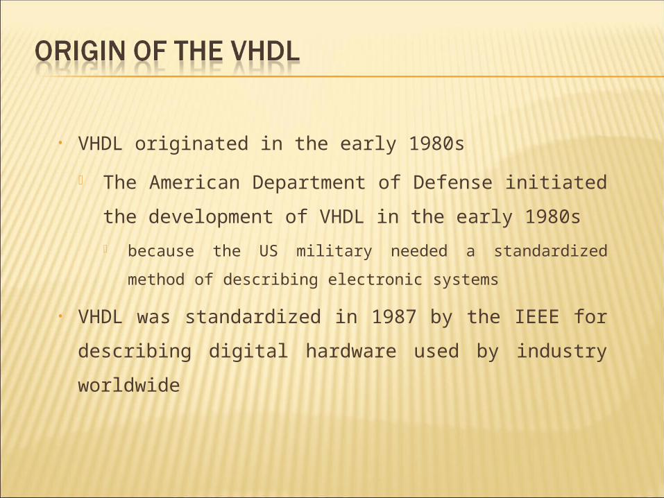
• VHDL originated in the early 1980s
The American Department of Defense initiated the
development of VHDL in the early 1980s
because the US military needed a standardized method of
describing electronic systems
• VHDL was standardized in 1987 by the IEEE for
describing digital hardware used by industry worldwide
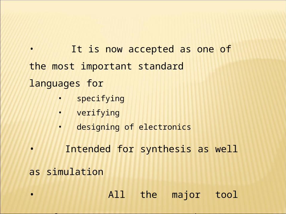
• It is now accepted as one of the most important
standard languages for
• specifying
• verifying
• designing of electronics
• Intended for synthesis as well as simulation
• All the major tool manufacturers now support the
VHDL standard
VHDL is a standard, technology/vendor independent language
Advantage: it is easy to move VHDL code between different
commercial platforms (Portable and reusable)
Concurrent statements not sequential VHDL is fully simulatable, not all constructs are
synthesizable
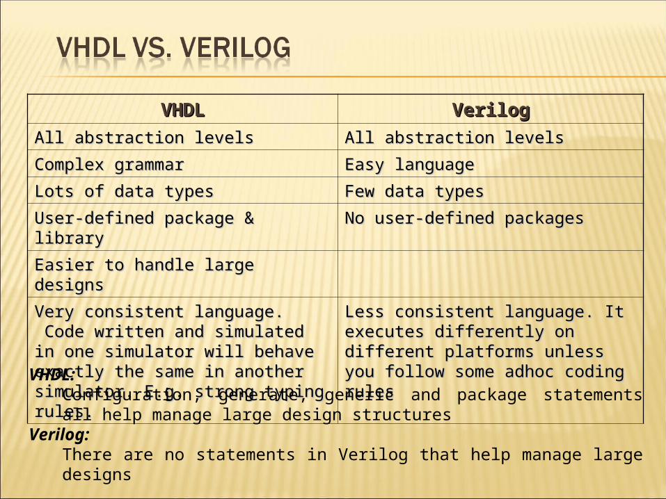
VHDLVHDL VerilogVerilog
All abstraction levelsAll abstraction levels All abstraction levelsAll abstraction levels
Complex grammarComplex grammar Easy languageEasy language
Lots of data typesLots of data types Few data typesFew data types
User-defined package & libraryUser-defined package & library No user-defined packagesNo user-defined packages
Easier to handle large designsEasier to handle large designs
Very consistent language. Code written and Very consistent language. Code written and simulated in one simulator will behave simulated in one simulator will behave exactly the same in another simulator.exactly the same in another simulator. E.g. E.g. strong typing rules.strong typing rules.
Less consistent language. Less consistent language. IItt executes executes differently on different platforms unlessdifferently on different platforms unless you follow some adhoc coding rulesyou follow some adhoc coding rules
VHDL:Configuration, generate, generic and package statements all help manage large design structures
Verilog:There are no statements in Verilog that help manage large designs
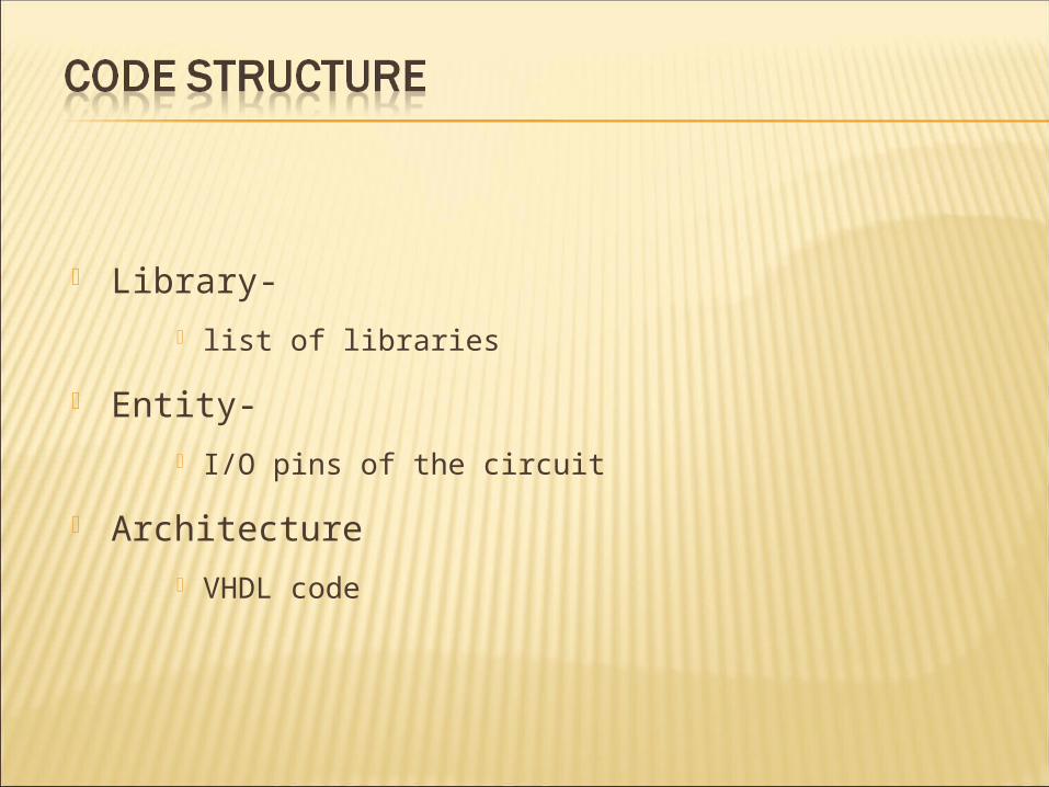
Library-
list of libraries
Entity-
I/O pins of the circuit
Architecture
VHDL code
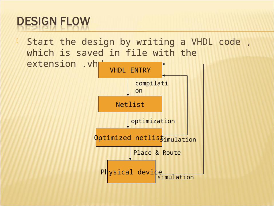
Start the design by writing a VHDL code , which is saved in file with the extension .vhd
VHDL ENTRY
Optimized netlist
Physical device
Netlist
compilation
optimization
Place & Route
simulation
simulation
Library-
list of libraries
Entity-
I/O pins of the circuit
Architecture
VHDL code
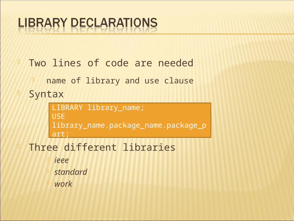
Two lines of code are needed
name of library and use clause
Syntax
Three different libraries ieee standard work
LIBRARY library_name;USE library_name.package_name.package_part;
Three packages from three different libraries
ieee.std_logic_1164
standard
work
std and work- default
ieee- explicitly written
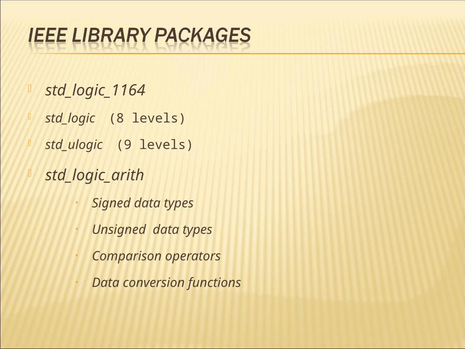
std_logic_1164
std_logic (8 levels)
std_ulogic (9 levels)
std_logic_arith
• Signed data types
• Unsigned data types
• Comparison operators
• Data conversion functions
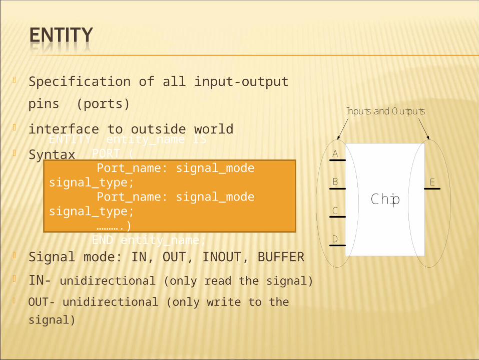
Specification of all input-output pins (ports)
interface to outside world
Syntax
Signal mode: IN, OUT, INOUT, BUFFER
IN- unidirectional (only read the signal)
OUT- unidirectional (only write to the signal)
ENTITY entity_name IS PORT (
Port_name: signal_mode signal_type; Port_name: signal_mode signal_type;
……….) END entity_name;
Inputs and Outputs
Chip
A
B
C
D
E

INOUT-bidirectional (read or write to the signal )
BUFFER- when output signal is read internally
Signal Type: BIT, STD_LOGIC, INTEGER
Entity name can be any name except VHDL reserved words
Entity name should be same as the file name
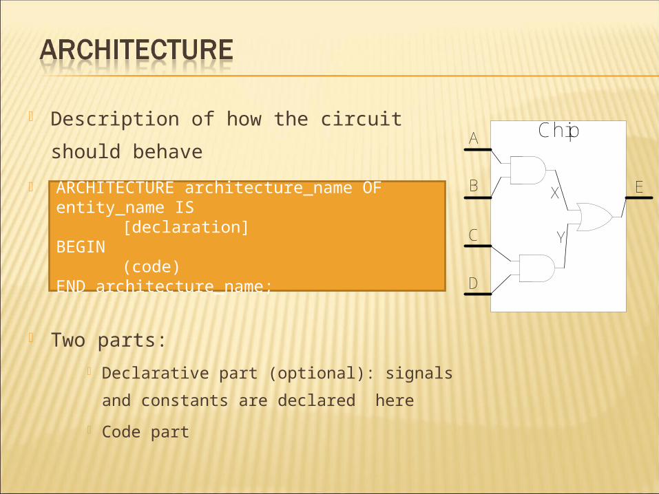
Description of how the circuit should behave
Syntax
Two parts:
Declarative part (optional): signals and
constants are declared here
Code part
ARCHITECTURE architecture_name OF entity_name IS
[declaration]BEGIN
(code)END architecture_name;
ChipA
B
C
D
EX
Y
The architecture declaration part must be defined before first
begin and can consist of, for example:
types
subprograms
components
signal declarations

Case insensitive inputa, INPUTA and InputA are refer to same variable
Comments ‘--’ If you want to comment multiple lines, ‘--’ need to be put at the
beginning of every single line
Statements are terminated by ‘;’ Signal assignment:
‘<=’
User defined names: letters, numbers, underscores (‘_’) start with a letter
Define the logic function
output <= inputa and inputb;
output is assigned to be inputa AND inputb
LHS contains only 1 variable only
RHS can be logics operations for many variables
18

All internal variables
Signal X,Y : std_logic;
Chip
Signal
A
B
C
D
EX
Y

LIBRARY IEEE;USE IEEE.STD_LOGIC_1164.ALL;
ENTITY TEST ISPORT (A,B,C,D : IN STD_LOGIC;
E : OUT STD_LOGIC);END TEST;
ARCHITECTURE BEHAVIOR OF TEST IS SIGNAL X,Y : STD_LOGIC;
BEGIN
X <= A AND B;Y <= C AND D;E <= X OR Y;
END BEHAVIOR;
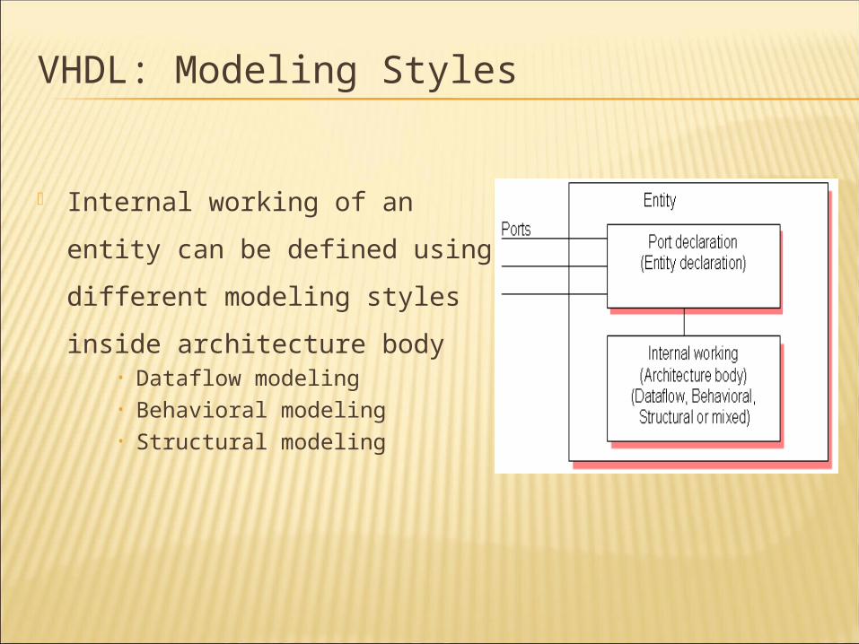
VHDL: Modeling Styles
Internal working of an entity can be
defined using different modeling
styles inside architecture body• Dataflow modeling• Behavioral modeling• Structural modeling
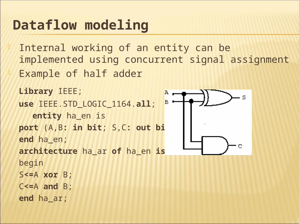
Dataflow modeling Internal working of an entity can be implemented using concurrent
signal assignment Example of half adder
Library IEEE;
use IEEE.STD_LOGIC_1164.all;
entity ha_en is
port (A,B: in bit; S,C: out bit);
end ha_en;
architecture ha_ar of ha_en is
begin
S<=A xor B;
C<=A and B;
end ha_ar;
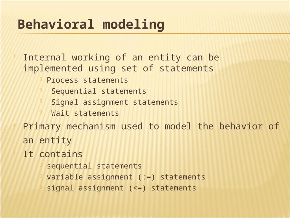
Behavioral modeling
Internal working of an entity can be implemented using set of statements
Process statements Sequential statements Signal assignment statements Wait statements
Primary mechanism used to model the behavior of an entity It contains
sequential statements variable assignment (:=) statements signal assignment (<=) statements
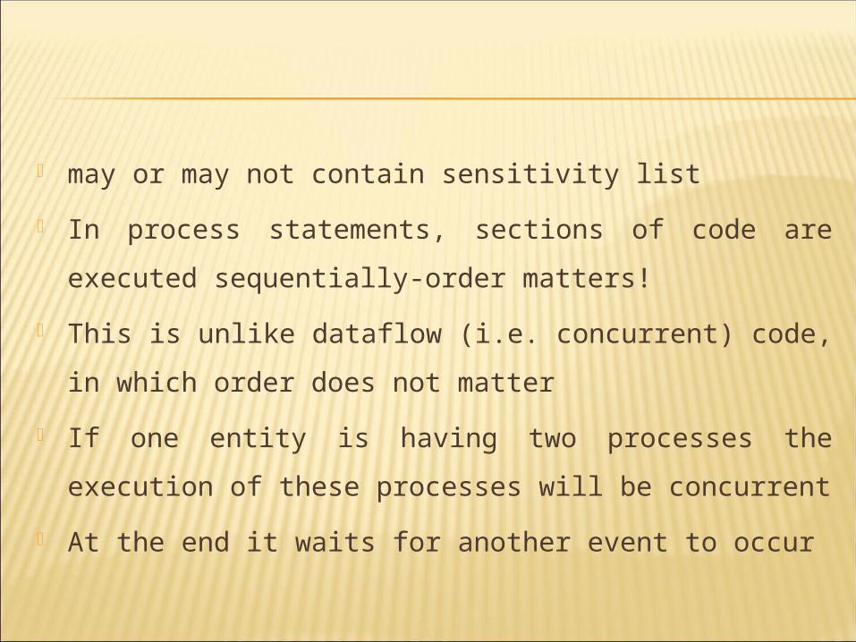
may or may not contain sensitivity list
In process statements, sections of code are executed sequentially-
order matters!
This is unlike dataflow (i.e. concurrent) code, in which order does
not matter
If one entity is having two processes the execution of these
processes will be concurrent
At the end it waits for another event to occur
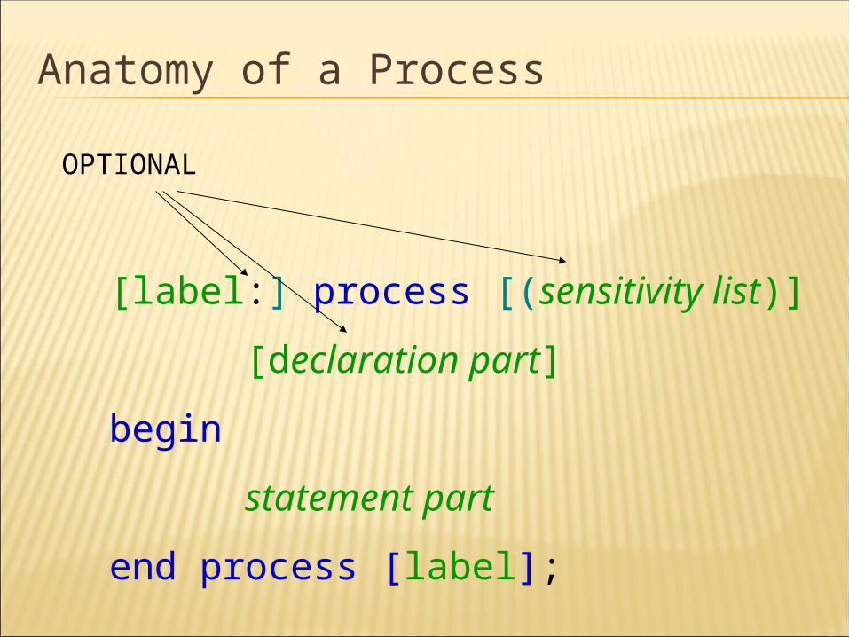
Anatomy of a Process
[label:] process [(sensitivity list)]
[declaration part]
begin
statement part
end process [label];
OPTIONAL
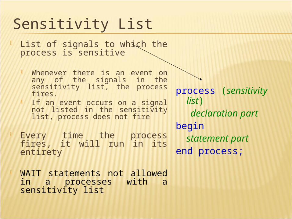
Sensitivity List List of signals to which the process
is sensitive
Whenever there is an event on any of the signals in the sensitivity list, the process fires.
If an event occurs on a signal not listed in the sensitivity list, process does not fire
Every time the process fires, it will run in its entirety
WAIT statements not allowed in a processes with a sensitivity list
process (sensitivity list)
declaration part begin
statement part end process;
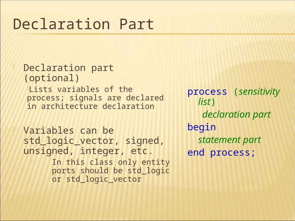
Declaration Part
Declaration part (optional)Lists variables of the process; signals are declared in architecture declaration
Variables can be std_logic_vector, signed, unsigned, integer, etc.
In this class only entity ports should be std_logic or std_logic_vector
process (sensitivity list)
declaration part begin
statement part end process;
Statement Part
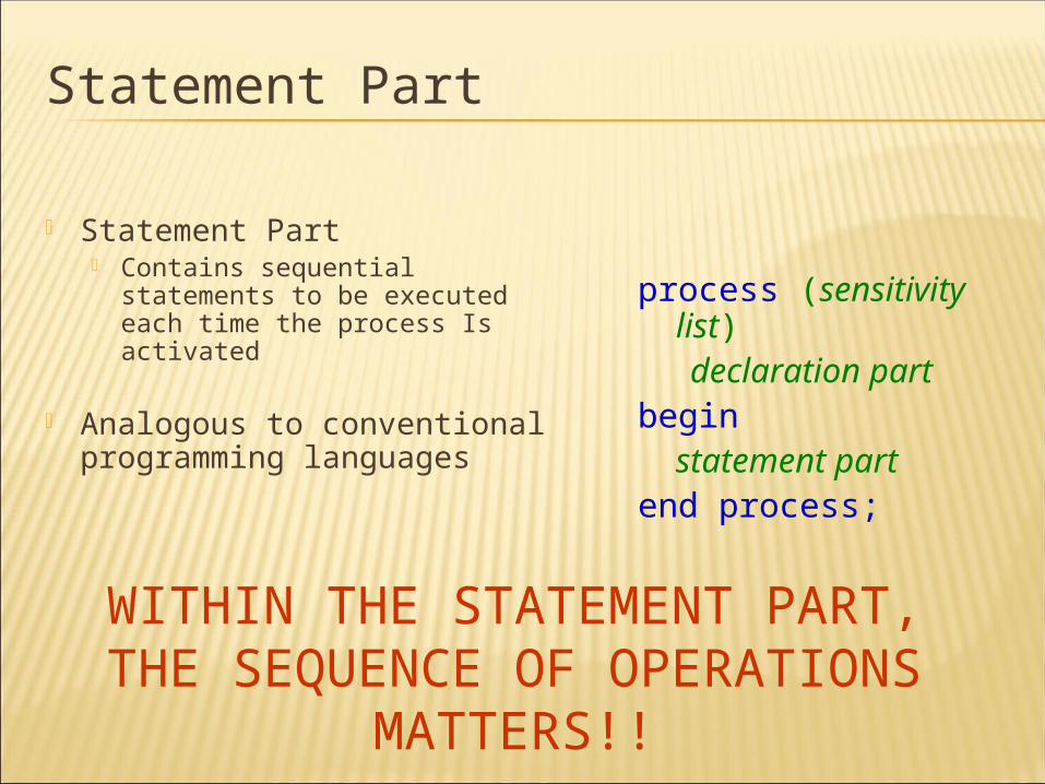
Statement Part Contains sequential statements to be
executed each time the process Is activated
Analogous to conventional programming languages
process (sensitivity list)
declaration part begin
statement part end process;
WITHIN THE STATEMENT PART, THE SEQUENCE OF OPERATIONS MATTERS!!
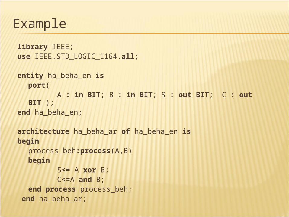
Example
library IEEE; use IEEE.STD_LOGIC_1164.all; entity ha_beha_en is
port( A : in BIT; B : in BIT; S : out BIT; C : out BIT );
end ha_beha_en;
architecture ha_beha_ar of ha_beha_en is begin
process_beh:process(A,B) begin
S<= A xor B; C<=A and B;
end process process_beh; end ha_beha_ar;
Structural modeling
Implementation of an entity is done through set of interconnected components
It contains: • Signal declaration. • Component instances • Port maps. • Wait statements.
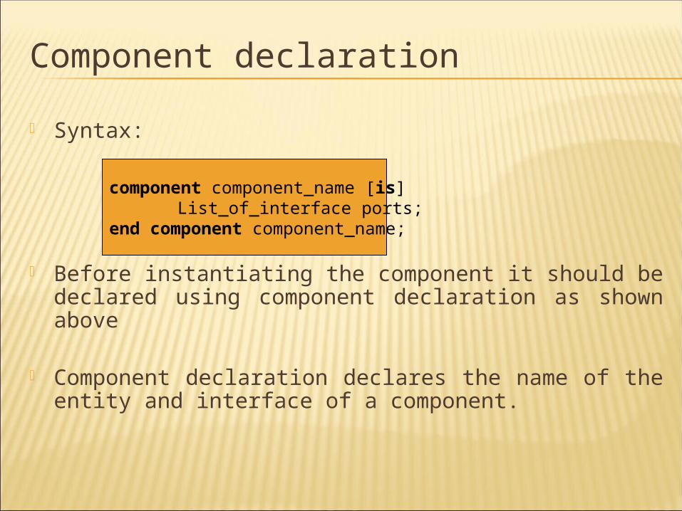
Component declaration
Syntax:
Before instantiating the component it should be declared using component declaration as shown above
Component declaration declares the name of the entity and interface of a component.
component component_name [is] List_of_interface ports; end component component_name;
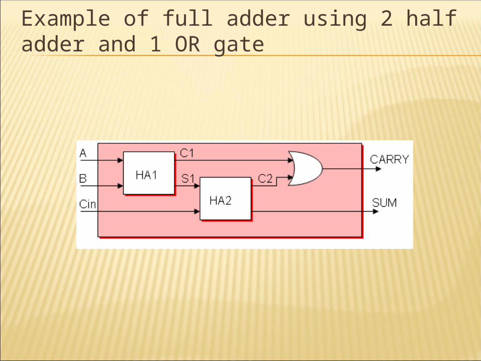
Example of full adder using 2 half adder and 1 OR gate
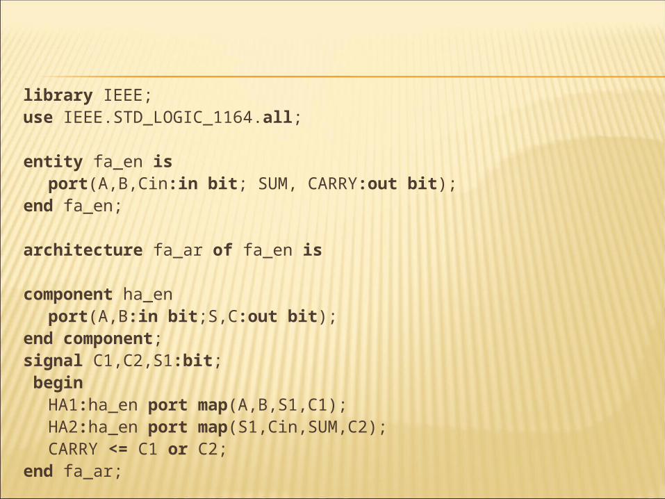
library IEEE; use IEEE.STD_LOGIC_1164.all;
entity fa_en is port(A,B,Cin:in bit; SUM, CARRY:out bit);
end fa_en;
architecture fa_ar of fa_en is
component ha_en port(A,B:in bit;S,C:out bit);
end component; signal C1,C2,S1:bit; begin
HA1:ha_en port map(A,B,S1,C1); HA2:ha_en port map(S1,Cin,SUM,C2); CARRY <= C1 or C2;
end fa_ar;