Embed Size (px)
Citation preview
MODEL TAF-550VHF/AM/FM Modular Communications
Technisonic VHF/AM/FM Modular Communications System
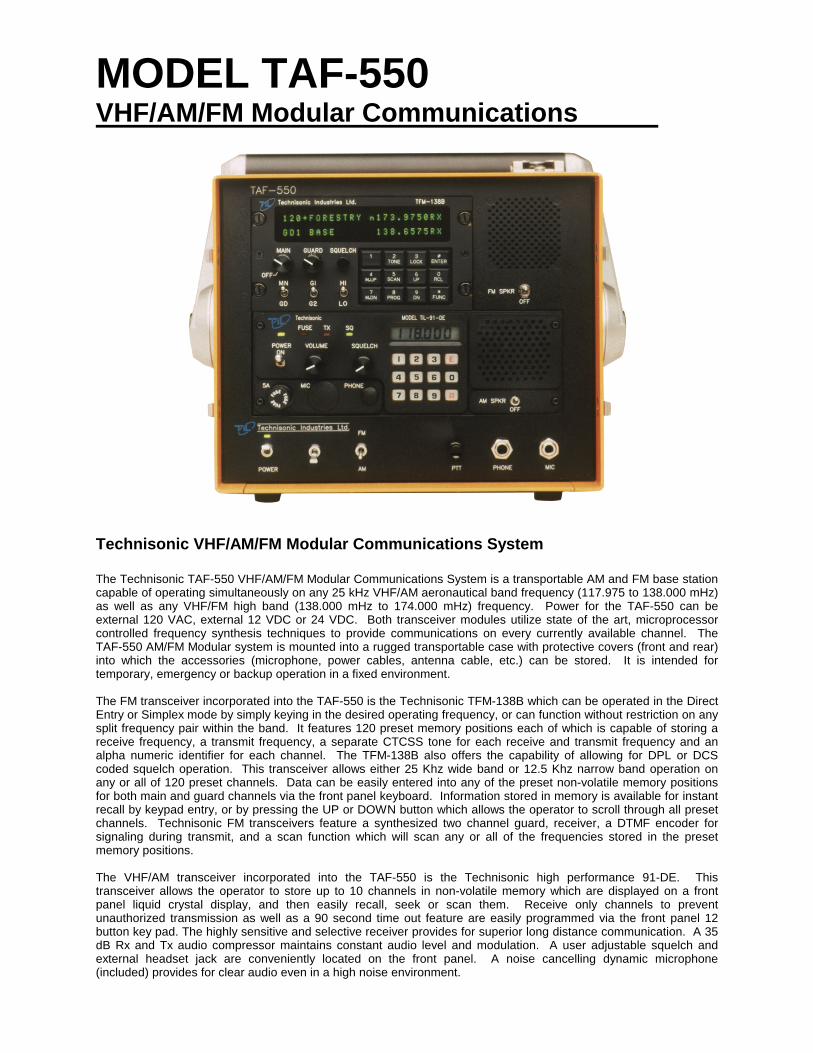
The Technisonic TAF-550 VHF/AM/FM Modular Communications System is a transportable AM and FM base stationcapable of operating simultaneously on any 25 kHz VHF/AM aeronautical band frequency (117.975 to 138.000 mHz)as well as any VHF/FM high band (138.000 mHz to 174.000 mHz) frequency. Power for the TAF-550 can beexternal 120 VAC, external 12 VDC or 24 VDC. Both transceiver modules utilize state of the art, microprocessorcontrolled frequency synthesis techniques to provide communications on every currently available channel. TheTAF-550 AM/FM Modular system is mounted into a rugged transportable case with protective covers (front and rear)into which the accessories (microphone, power cables, antenna cable, etc.) can be stored. It is intended fortemporary, emergency or backup operation in a fixed environment.
The FM transceiver incorporated into the TAF-550 is the Technisonic TFM-138B which can be operated in the DirectEntry or Simplex mode by simply keying in the desired operating frequency, or can function without restriction on anysplit frequency pair within the band. It features 120 preset memory positions each of which is capable of storing areceive frequency, a transmit frequency, a separate CTCSS tone for each receive and transmit frequency and analpha numeric identifier for each channel. The TFM-138B also offers the capability of allowing for DPL or DCScoded squelch operation. This transceiver allows either 25 Khz wide band or 12.5 Khz narrow band operation onany or all of 120 preset channels. Data can be easily entered into any of the preset non-volatile memory positionsfor both main and guard channels via the front panel keyboard. Information stored in memory is available for instantrecall by keypad entry, or by pressing the UP or DOWN button which allows the operator to scroll through all presetchannels. Technisonic FM transceivers feature a synthesized two channel guard, receiver, a DTMF encoder forsignaling during transmit, and a scan function which will scan any or all of the frequencies stored in the presetmemory positions.
The VHF/AM transceiver incorporated into the TAF-550 is the Technisonic high performance 91-DE. Thistransceiver allows the operator to store up to 10 channels in non-volatile memory which are displayed on a frontpanel liquid crystal display, and then easily recall, seek or scan them. Receive only channels to preventunauthorized transmission as well as a 90 second time out feature are easily programmed via the front panel 12button key pad. The highly sensitive and selective receiver provides for superior long distance communication. A 35dB Rx and Tx audio compressor maintains constant audio level and modulation. A user adjustable squelch andexternal headset jack are conveniently located on the front panel. A noise cancelling dynamic microphone(included) provides for clear audio even in a high noise environment.
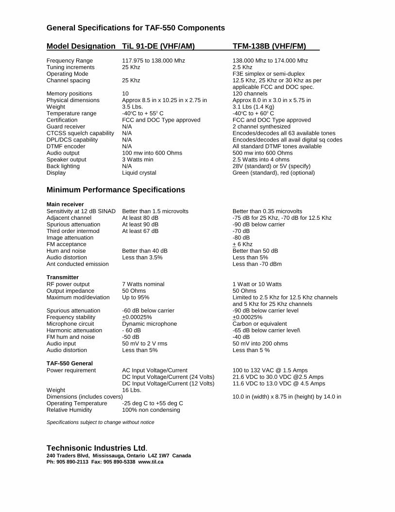
General Specifications for TAF-550 Components
Model Designation TiL 91-DE (VHF/AM) TFM-138B (VHF/FM)
Frequency Range 117.975 to 138.000 Mhz 138.000 Mhz to 174.000 MhzTuning increments 25 Khz 2.5 KhzOperating Mode F3E simplex or semi-duplexChannel spacing 25 Khz 12.5 Khz, 25 Khz or 30 Khz as per
applicable FCC and DOC spec.Memory positions 10 120 channelsPhysical dimensions Approx 8.5 in x 10.25 in x 2.75 in Approx 8.0 in x 3.0 in x 5.75 inWeight 3.5 Lbs. 3.1 Lbs (1.4 Kg)Temperature range -40oC to + 550 C -40oC to + 600 CCertification FCC and DOC Type approved FCC and DOC Type approvedGuard receiver N/A 2 channel synthesizedCTCSS squelch capability N/A Encodes/decodes all 63 available tonesDPL/DCS capability N/A Encodes/decodes all avail digital sq codesDTMF encoder N/A All standard DTMF tones availableAudio output 100 mw into 600 Ohms 500 mw into 600 OhmsSpeaker output 3 Watts min 2.5 Watts into 4 ohmsBack lighting N/A 28V (standard) or 5V (specify)Display Liquid crystal Green (standard), red (optional)
Minimum Performance Specifications
Main receiverSensitivity at 12 dB SINAD Better than 1.5 microvolts Better than 0.35 microvoltsAdjacent channel At least 80 dB -75 dB for 25 Khz, -70 dB for 12.5 KhzSpurious attenuation At least 90 dB -90 dB below carrierThird order intermod At least 67 dB -70 dBImage attenuation -80 dBFM acceptance + 6 KhzHum and noise Better than 40 dB Better than 50 dBAudio distortion Less than 3.5% Less than 5%Ant conducted emission Less than -70 dBm
TransmitterRF power output 7 Watts nominal 1 Watt or 10 WattsOutput impedance 50 Ohms 50 OhmsMaximum mod/deviation Up to 95% Limited to 2.5 Khz for 12.5 Khz channels
and 5 Khz for 25 Khz channelsSpurious attenuation -60 dB below carrier -90 dB below carrier levelFrequency stability +0.00025% +0.00025%Microphone circuit Dynamic microphone Carbon or equivalentHarmonic attenuation - 60 dB -65 dB below carrier level\FM hum and noise -50 dB -40 dBAudio input 50 mV to 2 V rms 50 mV into 200 ohmsAudio distortion Less than 5% Less than 5 %
TAF-550 GeneralPower requirement AC Input Voltage/Current 100 to 132 VAC @ 1.5 Amps
DC Input Voltage/Current (24 Volts) 21.6 VDC to 30.0 VDC @2.5 AmpsDC Input Voltage/Current (12 Volts) 11.6 VDC to 13.0 VDC @ 4.5 Amps
Weight 16 Lbs.Dimensions (includes covers) 10.0 in (width) x 8.75 in (height) by 14.0 inOperating Temperature -25 deg C to +55 deg CRelative Humidity 100% non condensing
Specifications subject to change without notice
Technisonic Industries Ltd.240 Traders Blvd, Mississauga, Ontario L4Z 1W7 CanadaPh: 905 890-2113 Fax: 905 890-5338 www.til.ca
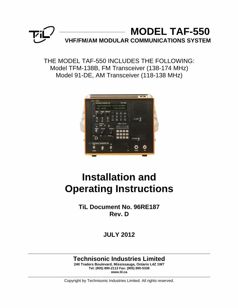
MODEL TAF-550 VHF/FM/AM MODULAR COMMUNICATIONS SYSTEM
THE MODEL TAF-550 INCLUDES THE FOLLOWING: Model TFM-138B, FM Transceiver (138-174 MHz)
Model 91-DE, AM Transceiver (118-138 MHz)
Installation and Operating Instructions
TiL Document No. 96RE187 Rev. D
JULY 2012
Technisonic Industries Limited 240 Traders Boulevard, Mississauga, Ontario L4Z 1W7
Tel: (905) 890-2113 Fax: (905) 890-5338 www.til.ca
Copyright by Technisonic Industries Limited. All rights reserved.

ii
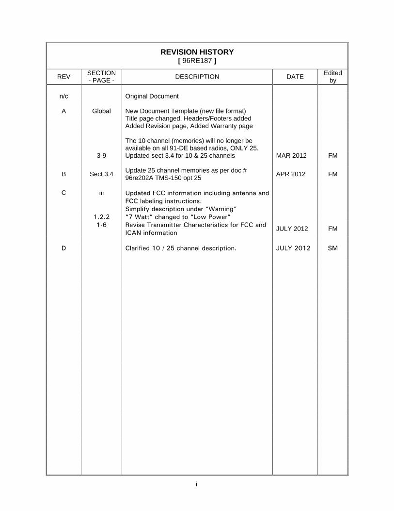
REVISION HISTORY [ 96RE187 ]
REV SECTION - PAGE - DESCRIPTION DATE Edited
by
n/c Original Document
A Global New Document Template (new file format) Title page changed, Headers/Footers added Added Revision page, Added Warranty page The 10 channel (memories) will no longer be
available on all 91-DE based radios, ONLY 25.
3-9 Updated sect 3.4 for 10 & 25 channels MAR 2012 FM
B Sect 3.4 Update 25 channel memories as per doc # 96re202A TMS-150 opt 25 APR 2012 FM
C iii Updated FCC information including antenna and
FCC labeling instructions.
Simplify description under “Warning” 1.2.2 “7 Watt” changed to “Low Power” 1-6 Revise Transmitter Characteristics for FCC and
ICAN information JULY 2012 FM
D Clarified 10 / 25 channel description. JULY 2012 SM

iiii
iii
WARNING Do not make physical contact with antenna when transmitter is on. CAUTION ! STATIC SENSITIVE !
This unit contains static sensitive devices. Wear a grounded wrist strap and/or conductive gloves when handling printed circuit boards.
FCC COMPLIANCE INFORMATION This device complies with Part 15 of the FCC Rules. Operation is subject to the following two conditions: (1) this device may not cause harmful interference and (2) this device must accept any interference received, including interference that may cause undesired operation.
WARNING: For compliance with FCC RF Exposure Requirements the mobile transmitter antenna installation shall comply with the following two conditions:
1. The transmitter antenna gain shall not exceed 3 dBi. 2. The transmitter antenna is required to be located outside of a vehicle and kept at a separation distance of 90 cm
or more between the transmitter antenna of this device and person(s) during operation. NOTE: This equipment has been tested and found to comply with the limits for a Class A digital device, pursuant to Part 15 of the FCC Rules. These limits are designed to provide reasonable protection against harmful interference when the equipment is operated in a commercial environment. This equipment generates, uses, and can radiate radio frequency energy and, if not installed and used in accordance with the instruction manual, may cause harmful interference to radio communications. Operation of this equipment in a residential area is likely to cause harmful interference, in which case the user will be required to correct the interference at his/her own expense. FCC LABELING INFORMATION: When this device is permanently mounted in an enclosure where the FCC ID label can not be seen, another label must be placed on the outside of the enclosure stating ‘contains FCC ID: IMA90-6R’. WARRANTY INFORMATION The TAF-550 Communications System is under warranty for one year from date of purchase. Failed units caused by defective parts, or workmanship should be returned to: Technisonic Industries Limited 240 Traders Boulevard Mississauga, Ontario L4Z 1W7 Tel: (905) 890-2113 Fax: (905) 890-5338

iv
TECHNISONIC INDUSTRIES LIMITED www.til.ca
TAF-550 Installation & Operating Instructions TiL 96RE187 Rev Dv
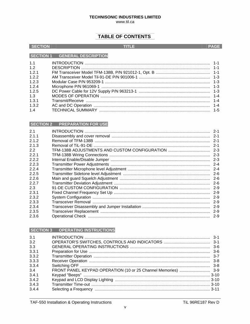
TABLE OF CONTENTS
SECTION TITLE PAGE
SECTION 1 GENERAL DESCRIPTION
1.1 INTRODUCTION ............................................................................................................... 1-1 1.2 DESCRIPTION .................................................................................................................. 1-1 1.2.1 FM Transceiver Model TFM-138B, P/N 921012-1, Opt. B ................................................ 1-1 1.2.2 AM Transceiver Model Til-91-DE P/N 901006-1 ............................................................... 1-3 1.2.3 Modular Case P/N 953209-1 ............................................................................................. 1-3 1.2.4 Microphone P/N 961069-1 ................................................................................................ 1-3 1.2.5 DC Power Cable for 12V Supply P/N 963213-1 ............................................................... 1-3 1.3 MODES OF OPERATION ................................................................................................. 1-4 1.3.1 Transmit/Receive .............................................................................................................. 1-4 1.3.2 AC and DC Operation ....................................................................................................... 1-4 1.4 TECHNICAL SUMMARY .................................................................................................. 1-5 SECTION 2 PREPARATION FOR USE
2.1 INTRODUCTION ............................................................................................................... 2-1 2.1.1 Disassembly and cover removal ....................................................................................... 2-1 2.1.2 Removal of TFM-138B ...................................................................................................... 2-1 2.1.3 Removal of TiL-91-DE ....................................................................................................... 2-1 2.2 TFM-138B ADJUSTMENTS AND CUSTOM CONFIGURATION ..................................... 2-3 2.2.1 TFM-138B Wiring Connections ......................................................................................... 2-3 2.2.2 Internal Enable/Disable Jumper ........................................................................................ 2-3 2.2.3 Transmitter Power Adjustments ........................................................................................ 2-4 2.2.4 Transmitter Microphone level Adjustment ......................................................................... 2-4 2.2.5 Transmitter Sidetone level Adjustment ............................................................................. 2-6 2.2.6 Main and guard Squelch Adjustment ................................................................................ 2-6 2.2.7 Transmitter Deviation Adjustment ..................................................................................... 2-6 2.3 91-DE CUSTOM CONFIGURATION ................................................................................ 2-9 2.3.1 Fixed Channel Frequency Set Up ..................................................................................... 2-9 2.3.2 System Configuration ........................................................................................................ 2-9 2.3.3 Transceiver Removal ........................................................................................................ 2-9 2.3.4 Transceiver Disassembly and Jumper Installation ............................................................ 2-9 2.3.5 Transceiver Replacement ................................................................................................. 2-9 2.3.6 Operational Check ............................................................................................................ 2-9 SECTION 3 OPERATING INSTRUCTIONS
3.1 INTRODUCTION ............................................................................................................... 3-1 3.2 OPERATOR'S SWITCHES, CONTROLS AND INDICATORS ......................................... 3-1 3.3 GENERAL OPERATING INSTRUCTIONS ....................................................................... 3-6 3.3.1 Preparation for Use ........................................................................................................... 3-6 3.3.2 Transmitter Operation ....................................................................................................... 3-7 3.3.3 Receiver Operation ........................................................................................................... 3-8 3.3.4 Switching OFF ................................................................................................................... 3-8 3.4 FRONT PANEL KEYPAD OPERATION (10 or 25 Channel Memories) ........................... 3-9 3.4.1 Keypad "Beeps" ................................................................................................................ 3-10 3.4.2 Keypad and LCD Display Lighting .................................................................................... 3-10 3.4.3 Transmitter Time-out ......................................................................................................... 3-10 3.4.4 Selecting a Frequency ...................................................................................................... 3-11
TECHNISONIC INDUSTRIES LIMITED www.til.ca
TAF-550 Installation & Operating Instructions TiL 96RE187 Rev Dvi
SECTION TITLE PAGE
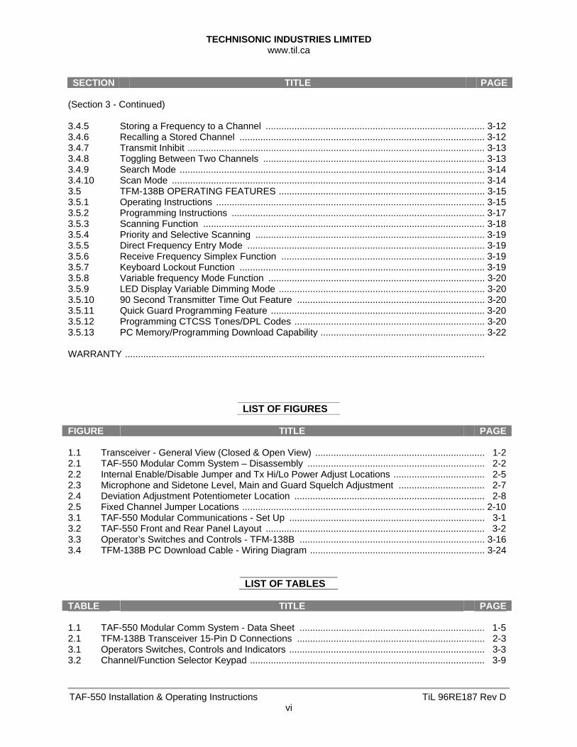
(Section 3 - Continued) 3.4.5 Storing a Frequency to a Channel .................................................................................... 3-12 3.4.6 Recalling a Stored Channel .............................................................................................. 3-12 3.4.7 Transmit Inhibit .................................................................................................................. 3-13 3.4.8 Toggling Between Two Channels ..................................................................................... 3-13 3.4.9 Search Mode ..................................................................................................................... 3-14 3.4.10 Scan Mode ........................................................................................................................ 3-14 3.5 TFM-138B OPERATING FEATURES ............................................................................... 3-15 3.5.1 Operating Instructions ....................................................................................................... 3-15 3.5.2 Programming Instructions ................................................................................................. 3-17 3.5.3 Scanning Function ............................................................................................................ 3-18 3.5.4 Priority and Selective Scanning ........................................................................................ 3-19 3.5.5 Direct Frequency Entry Mode ........................................................................................... 3-19 3.5.6 Receive Frequency Simplex Function .............................................................................. 3-19 3.5.7 Keyboard Lockout Function .............................................................................................. 3-19 3.5.8 Variable frequency Mode Function ................................................................................... 3-20 3.5.9 LED Display Variable Dimming Mode ............................................................................... 3-20 3.5.10 90 Second Transmitter Time Out Feature ........................................................................ 3-20 3.5.11 Quick Guard Programming Feature .................................................................................. 3-20 3.5.12 Programming CTCSS Tones/DPL Codes ......................................................................... 3-20 3.5.13 PC Memory/Programming Download Capability ............................................................... 3-22 WARRANTY ..........................................................................................................................................
LIST OF FIGURES FIGURE TITLE PAGE 1.1 Transceiver - General View (Closed & Open View) ................................................................. 1-2 2.1 TAF-550 Modular Comm System – Disassembly .................................................................... 2-2 2.2 Internal Enable/Disable Jumper and Tx Hi/Lo Power Adjust Locations ................................... 2-5 2.3 Microphone and Sidetone Level, Main and Guard Squelch Adjustment ................................. 2-7 2.4 Deviation Adjustment Potentiometer Location ......................................................................... 2-8 2.5 Fixed Channel Jumper Locations ............................................................................................. 2-10 3.1 TAF-550 Modular Communications - Set Up ........................................................................... 3-1 3.2 TAF-550 Front and Rear Panel Layout .................................................................................... 3-2 3.3 Operator’s Switches and Controls - TFM-138B ....................................................................... 3-16 3.4 TFM-138B PC Download Cable - Wiring Diagram ................................................................... 3-24
LIST OF TABLES TABLE TITLE PAGE 1.1 TAF-550 Modular Comm System - Data Sheet ....................................................................... 1-5 2.1 TFM-138B Transceiver 15-Pin D Connections ........................................................................ 2-3 3.1 Operators Switches, Controls and Indicators ........................................................................... 3-3 3.2 Channel/Function Selector Keypad .......................................................................................... 3-9
TECHNISONIC INDUSTRIES LIMITED www.til.ca
TAF-550 Installation & Operating Instructions TiL 96RE187 Rev D1-1
SECTION 1 - GENERAL DESCRIPTION
1.1 INTRODUCTION The Model TAF-550 Modular Communications System No. 960200, manufactured by Technisonic Industries Limited, consisting of a VHF/FM and a VHF/AM Transceiver complete with an AC and DC power supply, microphone and power cables. The TFM-138B is a frequency agile fully synthesized FM transceiver offering an extended operating frequency range of 138-174 MHz with selectable wide/narrow band channel spacing. The Model 91-DE is a microprocessor controlled, simplex AM transceiver operating over the frequency range of 117.975 MHz to 138.000 MHz. The Modular Communications system is intended for temporary, emergency or backup operation in a fixed environment. The system can operate from external AC power, external 12 Volt DC power, or external 24 Volt DC power.
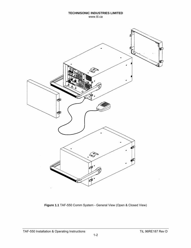
1.2 DESCRIPTION The TAF-550 Modular Communications System consists of FM Transceiver TFM-138B P/N 921012-1 Option B, AM Transceiver Model TiL 91-DE P/N 901006-2, Modular Case P/N 953209-1, Microphone P/N 861902-1, AC Power Cord P/N 927002-1, DC cable Assembly P/N 963213-1 (12 Volt) and Optional DC Cable P/N 93212-1 (24 Volt). The rear panel access cover houses the microphone, AC power cord, DC power cable assemblies and 2.5 Amp SLO blow fuse (AC), 5 Amp fuse (12 Volt DC) and 3 Amp fuse (24 Volt DC). Refer to Figure 1.1 for details.
1.2.1 FM Transceiver Model TFM-138B, P/N 921012-1, Opt. B
The TFM-138B, Transceiver is a frequency agile, fully synthesized airborne transceiver capable of operating in the 138.000 MHz to 174.000 MHz frequency range in 2.5 kHz increments with either 25 kHz or 12.5 kHz channel spacing. The Transceiver can operate without restriction on any split frequency pair in the band and also incorporates a two channel synthesized guard receiver.
The TFM-138B Transceiver provides 120 operator accessible memory positions, each of which is capable of storing a transmit frequency, receive frequency, transmit frequency CTCSS tone or DPL code, receive frequency CTCSS tone or DPL code, an alphanumeric identifier for each channel and for wideband (25 kHz) or narrowband (12.5 kHz) channel spacing assignment. Operating frequency and other related data are presented on a 48 character, two line LED matrix display. Data entry and function control are performed via a 12 button keypad. Preset channels may also be scrolled and scanned through keypad function activation. Data may also be entered via an MS-DOS based computer with the provided software and optional PC download cable, P/N 943165-1. A DB-15 connector is provided on the rear panel of the TAF-550 chassis to facilitate the PC download function of the TFM-138B without the need to remove it from the TAF-550 chassis.
TECHNISONIC INDUSTRIES LIMITED www.til.ca
TAF-550 Installation & Operating Instructions TiL 96RE187 Rev D1-2
Figure 1.1 TAF-550 Comm System - General View (Open & Closed View)
TECHNISONIC INDUSTRIES LIMITED www.til.ca
TAF-550 Installation & Operating Instructions TiL 96RE187 Rev D1-3
1.2.2 AM Transceiver Model TiL-91-DE, P/N 901006-2
The Transceiver is a microprocessor controlled VHF/AM transceiver operating over the entire band of 117.975 to 138.000 MHz in 25 kHz steps. The transceiver will store 10 or 25 user selected frequency channels in addition to the resident emergency channel of 121.500 MHz. The TiL-91-DE transceiver was available in either 10 or 25 channel versions until July 2012. The 25 channel version can be identified by ‘25’ or ‘1283T’ on the option label on those units. All units manufactured after July 2012 are 25 channel only. Frequency Selection, Storage, Recall, Channel Scan, Search, and Toggle modes are all selected by the 12-key keypad. Current operating frequency is displayed on a backlit liquid crystal display (LCD).
1.2.3 Modular Case P/N 953209-1
In addition to housing the two previously mentioned transceivers, the TAF-550 Modular case consists of an AC to DC Power Supply Module, a DC to DC Power Supply Module and a speaker for the TFM-138B. 1. AC to DC POWER SUPPLY MODULE - The AC Power Supply Module provides the 27.5
VDC supply voltage to the TFM-138B and 91-DE Transceivers, and houses a battery charger which will provide a combination constant current constant voltage charging and trickle charging to an optional external 24 Volt Battery connected to the DC connector (24 VDC output only).
2. DC to DC POWER SUPPLY MODULE - Provides the ability to power the TAF-550 with
an external 12 VDC supply. The dc to dc convertor steps the 12 VDC input to the required 27.5 VDC to operate the TFM-138B and 91-DE Transceivers.
3. SPEAKER - With on/off switching function. Speaker will monitor the receive audio from
the TFM-138B. The speaker may also be switched off if a headset is used to access the receive audio from the TAF-550 front panel phone connector. The 91-DE Transceiver utilizes an internal speaker for this purpose.
The lower front panel of the TAF-550 Modular Case provides a main power on/off switch, a transceiver backlighting on/off switch, a FM/AM transceiver selection switch, a PTT test button a 1/4" headphone connector and 0.2" microphone connector.
1.2.4 Microphone P/N 961069-1
The microphone is a rugged hand-held microphone housed in a high impact plastic case. The dynamic microphone is a noise canceling type with a two-stage preamplifier, press to talk switch, and a retractable three-core cable terminated by a standard 0.2" aviation jack which mates with the MIC/PTT connector located on the front panel of the transceiver. The microphone dc supply for the microphone is supplied by the transceiver. The microphone is stored in the rear access compartment for transportation. A mounting hardware kit consisting of a microphone mounting clip and clip mounting screws is also provided.
1.2.5 DC Power Cable for 12V Supply P/N 963213-1
DC Power Cable Part Number 963213-1 is provided with the TAF-550. This cable is configured to allow operation with a 12 VDC supply. Pin 1 (12V input) and Pin 2 (ground) are wired on the connector for this cable assembly. Optional 24V DC Power Cable P/N 963212-1 utilizes the same connector but has Pin 2 (ground) and Pin 3 (24 V input) wired. The DC power cable is stored in the rear panel access cover.
TECHNISONIC INDUSTRIES LIMITED www.til.ca
TAF-550 Installation & Operating Instructions TiL 96RE187 Rev D1-4
1.3 MODES OF OPERATION
The FM/AM selector switch located on the front panel of the TAF-550 is used to select operation of either the TFM-138B FM Transceiver or the 91-DE AM Transceiver. The receive audio of the selected transceiver will be routed over the headphone jack. Similarity the microphone connected to the TAF-550 front panel will route transmit audio to the selected transceiver. Speaker Rx audio for each transceiver can be manually turned on or off by the switch located under each speaker.
1.3.1 Transmit/Receive
Each transceiver may be operated in either of two modes; transmit or receive, as selected by the Press-to-Talk (PTT) switch on the microphone. (1) TRANSMIT MODE - When the PTT switch on the microphone is pressed, the transceiver
operates in the transmit mode. The PTT signal line is grounded by the microphone PTT switch via the microphone lead and the MIC/PTT connector to the transceiver.
On the TFM-138B either a “TX” or “TT” will be shown after the frequency on the alphanumeric LED display. A “TT” rather than a “TX” indicates that either a transmit CTCSS tone or DPL code has been programmed.
For the 91-DE the Tx ON amber LED will go ON, indicating that the transmitter is activated. Transmission will occur on the channel frequency displayed on the Liquid Crystal Display (LCD). Frequency is determined by keypad entry of the operating frequency or by recalling a stored channel.
(2) RECEIVE MODE - When the PTT switch on the microphone is released, the transceiver operates in the receive mode.
On the TFM-138B either a “RX” or “RT” will be shown after the frequency on the alphanumeric LED display. A “RT” as opposed to an “RX” means that a receive CTCSS tone or DPL code has been programmed.
In the receive mode on the 91-DE the Tx ON amber LED will go OFF, indicating that the transmitter is inhibited. Reception of the frequency displayed on the LCD will occur.
For the 91-DE the setting of the SQUELCH CONTROL determines the squelch threshold level. When the SQUELCH CONTROL is rotated in the counter-clockwise direction, the SQUELCH INDICATOR green LED will go ON, indicating that the squelch circuit is connecting the demodulated audio to the VOLUME CONTROL. The setting of the VOLUME CONTROL determines the audio level produced from the internal speaker. When the VOLUME CONTROL is adjusted in the clockwise direction, the audio level will increase.
The TFM-138B main and guard receiver squelch settings are located on the bottom panel of the TFM-138B chassis. The TFM-138B squelch is factory set to 0.5uV.
1.3.2 AC and DC Operation
The unit can be operated by external 120 VAC, external 28 VDC, or external 12 VDC power.
1. AC OPERATION - An AC power cord P/N 927002-1 is supplied in the rear access cover of the portable case assembly. During AC operation, the operator can elect to trickle charge external batteries (24 V only) when connected to the DC connector configured for 24 Volts.
2. DC OPERATION - The unit can be operated from an external 24V DC supply within the range of 21.6 VDC to 30 VDC. A DC connector is mounted on the rear of the Modular Chassis which mates with DC Power Cable P/N 963212-1 (Not Supplied) to facilitate external DC operation. DC Power Cable P/N 963213-1 will allow operation with a 12V DC external input supply and is included with The TAF-550 System.
TECHNISONIC INDUSTRIES LIMITED www.til.ca
TAF-550 Installation & Operating Instructions TiL 96RE187 Rev D1-5
1.4 TECHNICAL SUMMARY
A summary of electrical, operational, mechanical and physical characteristics of the transceivers, modular case and microphone indicated in Tables 1.1.
TABLE 1.1 TAF-550 MODULAR COMM SYSTEM - DATA SHEET GENERAL:
Power Requirements: AC Input Voltage/Current …………………………………………..….. 100 to 132 VAC @ 1.5 Amp DC Input Voltage/Current (24V configuration ……………….... 2)1.6 VDC to 30 VDC @ 2.5 Amp DC Input Voltage/Current (12V configuration) ….……………..... 1.6 VDC to 13 VDC @ 4.5 Amp Frequency Range, TFM-138B (FM) ………………………….………………….. 138.000 to 174.000 MHz Number of Channels (TFM-138B) ………………………….….... (120) programmable memory positions Frequency Range, 91-DE (AM) ………………………………………………….. 117.975 to 138.000 MHz Number of Channels (91-DE) ……………………………………………………………….. Ten (10) preset
Temperature & Humidity: Operating Temperature Range ………………………………..….. -25°C(-13°F) to +55°C(+131°F) Storage Temperature Range ………………………………….…... -55°C(-67°F) to +65°C(+149°F) Relative Humidity ……………………………………………………………... 100% non-condensing Microphone Compression Range ……………………….…….………………………………... 35 dB Antenna: Impedance ……………………………………………….…………………….…………..…..….. 50 VSWR …………………………………………………………….…………….…………..….. 4:1 MAX Dimensions & Weight (excluding Front and Rear Covers): Width X Height X Depth ……………………………………………….... 10.0 X 8.75 X 14.0 in MAX Weight ……………………………………………………………………………………..... 16 lbs MAX
MODEL TFM-138B TRANSCEIVER: TRANSMITTER: RF Power Output …………………………….………………………………………….. 1 or 10 Watts Output Impedance …………………………..…………………………………………….….. 50 ohms Maximum Deviation …………………….….. ±5 kHz (25 kHz mode) or ±2.5 kHz (12.5 kHz mode) Spurious Attenuation …………………..………………………………….…….. -90 dB below carrier Frequency Stability (-20°C to +55°C) …….……………………………………….... ±0.0005% MAX Microphone Circuit …………………………..………………………………..... Carbon or equivalent Sidetone Output ……………………………..…………………………... 0.5W (max) into 600 ohms Harmonic Attenuation ……………………..…………………………………….. -65dB below carrier FM Hum and Noise ………………………..…………………………………..... -40 dB below carrier Audio Input …...... 50 millivolts at 2.5kHz into 200 ohm input circuit for ±3.5kHz deviation, adjst. Audio Distortion ……………………………………………………………………….……..... 5% MAX
MAIN RECEIVER: Sensitivity (12 dB SINAD) ………………………………………………….... better than 0.35 μvolts Adjacent Channel Selectivity 25 kHz Channel Spacing ………….………………………………………………….... -70dB 12.5 kHz Channel Spacing …………………………………………………………….. -70dB Spurious Attenuation …………………………………………………………………………….. -90dB Third Order Intermodulation …………………………………………………………………….. -70dB Image Attenuation …………………………………………………………………………….….. -80dB FM Acceptance …………………………………………………………………………………... ±6kHz Hum & Noise ……………………………………………………………………………….... 50 dB MIN Antenna Conducted Emission ………………………………………………………….. -70 dBm MIN
GUARD RECEIVER: All specifications identical to main receiver
TECHNISONIC INDUSTRIES LIMITED www.til.ca
TAF-550 Installation & Operating Instructions TiL 96RE187 Rev D1-6
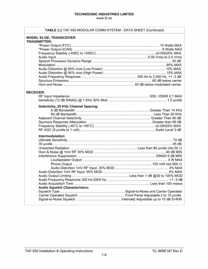
TABLE 1.1 TAF-550 MODULAR COMM SYSTEM - DATA SHEET (Continued)
MODEL 91-DE, TRANSCEIVER TRANSMITTER: *Power Output (FCC) ..............................................…………………………...…… 10 Watts MAX *Power Output (ICAN) …………………………………………………………………… 8 Watts MAX Frequency Stability (-40EC to +55EC) ………………………………………….... ±0.00025% MAX Audio Input …………………………………………………………………….. 0.05 Vrms to 2.0 Vrms Speech Processor Dynamic Range ………………………………………………………….... 35 dB Modulation ………………………………………………………………………………….... 95% MAX Audio Distortion @ 90% mod (Low Power) …………………………………………….... 10% MAX Audio Distortion @ 90% mod (High Power) …………………………………………….... 15% MAX Audio Frequency Response ……………………………………….... 300 Hz to 2,500 Hz, +1 -3 dB Spurious Emissions …………………………………………………………….... 60 dB below carrier Hum and Noise ……………………………………………………... 45 dB below modulated carrier RECEIVER: RF Input Impedance ………………………………………………………..….. 50S, VSWR 2:1 MAX Sensitivity (12 dB SINAD) @ 1 KHz 30% Mod ………………………………………..….. 1.5 μvolts
Selectivity, 25 KHz Channel Spacing: 6 dB Bandwidth ……………………………………………………….. Greater Than 14 KHz 90 dB Bandwidth ……………………………………………………….... Less Than 50 KHz Adjacent Channel Selectivity …………………………………………………... Greater Than 90 dB Spurious Response Attenuation …………………………………………….….. Greater than 95 dB Frequency Stability (-40°C to +55°C) …………………………………………….. ±0.00025% MAX RF AGC (5 μvolts to 1 volt) …………………………………………………….….. Audio Level 3 dB
Intermodulation: Ultimate Sensitivity ……………………………………………………………………………….. 70 dB 30 μvolts …………………………………………………………………………………………... 45 dB Unwanted Radiation ………………………………………………….. Less than 80 μvolts into 50 Hum & Noise @ 1mV RF 30% MOD ……………………………………………………... 40 dB MIN Interference Suppression …………………………………………………………... SINAD 6 dB MIN Loudspeaker Output ………………………………………………………………... 3 W MAX Phone Output ………………………………………………………….... 100 mW into 600 Audio Distortion 1mV RF Input, 30% MOD ……………………………………….. 3% MAX Audio Distortion 1mV RF Input, 90% MOD ……………………………………………….... 6% MAX Audio Output Limiting ………………………………………….. Less than 1 dB @30 to 100% MOD Audio Frequency Response 300 Hz-2500 Hz …………………………………………….... +1 -3 dB Audio Acquisition Time ……………………………………………………….... Less than 100 msecs Audio Squelch Characteristics: Squelch Type ………………………………………………... Signal-to-Noise and Carrier Operated Carrier Operated Squelch ………………………………….. Front Panel Adjustable 2 to 15 μvolts Signal-to-Noise Squelch ……………………………….... Internally Adjustable up to 15 dB S+N/N
TECHNISONIC INDUSTRIES LIMITED www.til.ca
TAF-550 Installation & Operating Instructions TiL 96RE187 Rev D2-1
SECTION 2 – PREPARATION FOR USE 2.1 INTRODUCTION
This section provides the information required for the removal, replacement, adjustment and/ or custom configuration of the self-contained modular TFM-138B and 91-DE Transceivers. Custom configuration and adjustments on the TFM-138B include; Internal enable/disable Jumper selection, Tx power adjustment, Tx microphone level adjustment, Tx side tone level adjustment, Main and Guard squelch adjustment and Transmitter deviation adjustment. Custom configuration for the 91-DE Transceiver includes customizing channel frequencies. Channels 0 to 9 can be configured for fixed frequency operation including transmit inhibit on pres-elected channels.
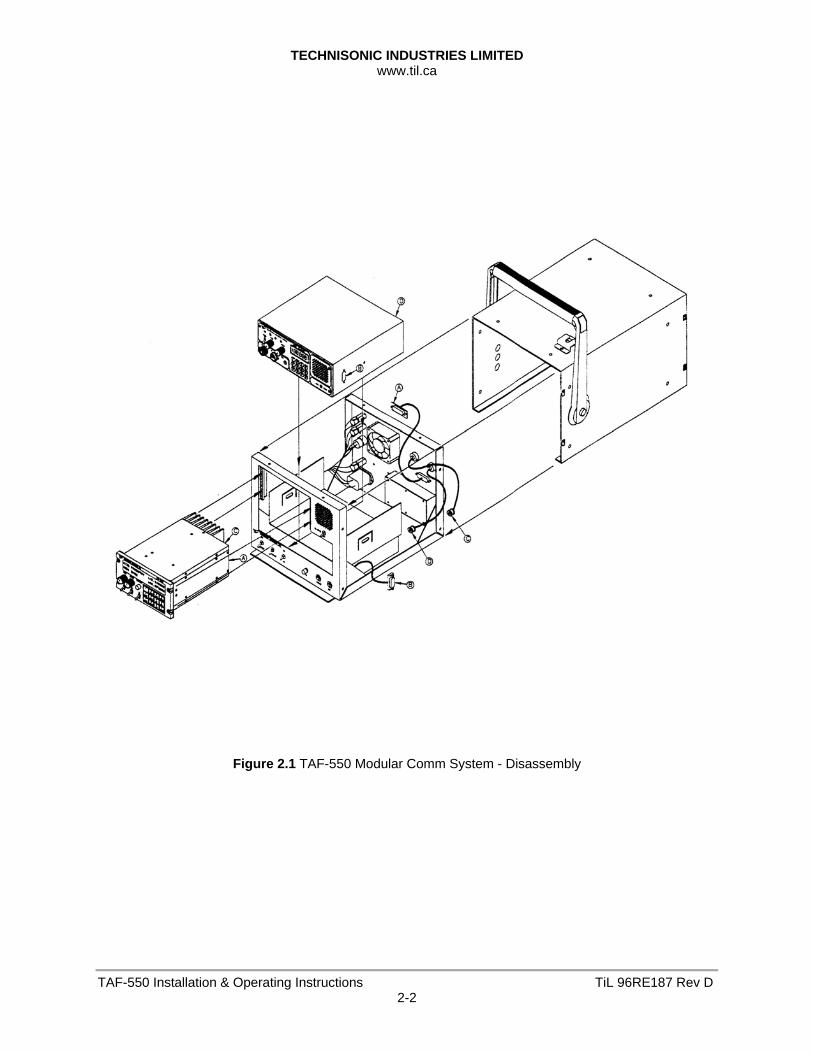
2.1.1 Disassembly and cover removal (Refer Figure 2.1)
(1) Release the (4) clip fasteners securing each front and back cover.
(2) Remove and retain (4) bottom screws and (4) top screws securing cover to chassis.
(3) Remove and retain (4) screws on each side securing cover to chassis, then slide the cover forward and lift it clear of the chassis.
(4) Reverse the order of the above steps to replace the cover on the TAF-550 chassis.
2.1.2 Removal of TFM-138B)
(1) Remove TAF-550 cover as described above and then release the (4) Dzus rail mounting
screws on the front panel of the TFM-138B.
(2) Remove the BNC RF connection from the back of the TFM-138B and then slide it out approximately 3 inches forward through the front cut-out of the TAF-550 chassis.
(3) Undo the (2) slotted screws securing the DB-9 connector on the back of the TFM-138B and slide the unit out of the TAF-550 chassis front cut-out.
(4) Reverse the order of the above steps to re-install the TFM-138B Transceiver.
2.1.3 Removal of the TiL-91-DE
(1) Remove the TAF-550 cover and the TFM-138B as described in the previous paragraphs.
Remove the two large mounting screws securing each side of the 91-DE Transceiver.
(2) Disconnect the two screws securing the DB-9 remote connector on the right side of the 91-DE Transceiver. Remove the DB-9 connector and pull the 91-DE Transceiver approximately 1 inch through the front cut-out of the TAF-550 chassis.
(3) Remove the DC and UHF RF connectors located on the back of the 91-DE chassis.
(4) Slide the 91-DE chassis back through the TAF-550 front cut-out and lift up and out of the back of the TAF-550 chassis.
(5) Reverse the order of the above steps to re-install the TiL-91-DE Transceiver in the TAF-550 modular chassis.
TECHNISONIC INDUSTRIES LIMITED www.til.ca
TAF-550 Installation & Operating Instructions TiL 96RE187 Rev D2-2
Figure 2.1 TAF-550 Modular Comm System - Disassembly
TECHNISONIC INDUSTRIES LIMITED www.til.ca
TAF-550 Installation & Operating Instructions TiL 96RE187 Rev D2-3
2.2 TFM-138B ADJUSTMENTS AND CUSTOM CONFIGURATION
Custom configuration and adjustments on the TFM-138B include; Internal enable/disable Jumper selection, Transmitter power adjustment, Transmitter microphone level adjustment, Transmitter side tone level adjustment, Main and Guard squelch adjustment and Transmitter deviation adjustment. The TFM-138B wiring connections are also provided.
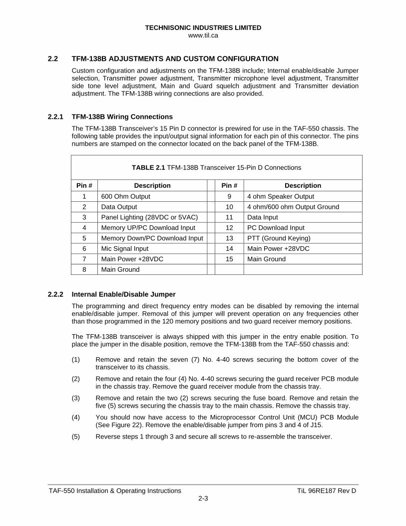
2.2.1 TFM-138B Wiring Connections
The TFM-138B Transceiver’s 15 Pin D connector is prewired for use in the TAF-550 chassis. The following table provides the input/output signal information for each pin of this connector. The pins numbers are stamped on the connector located on the back panel of the TFM-138B.
TABLE 2.1 TFM-138B Transceiver 15-Pin D Connections
Pin # Description Pin # Description 1 600 Ohm Output 9 4 ohm Speaker Output 2 Data Output 10 4 ohm/600 ohm Output Ground 3 Panel Lighting (28VDC or 5VAC) 11 Data Input 4 Memory UP/PC Download Input 12 PC Download Input 5 Memory Down/PC Download Input 13 PTT (Ground Keying) 6 Mic Signal Input 14 Main Power +28VDC 7 Main Power +28VDC 15 Main Ground 8 Main Ground
2.2.2 Internal Enable/Disable Jumper
The programming and direct frequency entry modes can be disabled by removing the internal enable/disable jumper. Removal of this jumper will prevent operation on any frequencies other than those programmed in the 120 memory positions and two guard receiver memory positions. The TFM-138B transceiver is always shipped with this jumper in the entry enable position. To place the jumper in the disable position, remove the TFM-138B from the TAF-550 chassis and: (1) Remove and retain the seven (7) No. 4-40 screws securing the bottom cover of the
transceiver to its chassis.
(2) Remove and retain the four (4) No. 4-40 screws securing the guard receiver PCB module in the chassis tray. Remove the guard receiver module from the chassis tray.
(3) Remove and retain the two (2) screws securing the fuse board. Remove and retain the five (5) screws securing the chassis tray to the main chassis. Remove the chassis tray.
(4) You should now have access to the Microprocessor Control Unit (MCU) PCB Module (See Figure 22). Remove the enable/disable jumper from pins 3 and 4 of J15.
(5) Reverse steps 1 through 3 and secure all screws to re-assemble the transceiver.
TECHNISONIC INDUSTRIES LIMITED www.til.ca
TAF-550 Installation & Operating Instructions TiL 96RE187 Rev D2-4
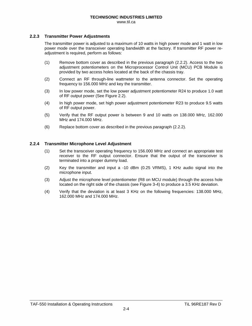
2.2.3 Transmitter Power Adjustments
The transmitter power is adjusted to a maximum of 10 watts in high power mode and 1 watt in low power mode over the transceiver operating bandwidth at the factory. If transmitter RF power re-adjustment is required, perform as follows: (1) Remove bottom cover as described in the previous paragraph (2.2.2). Access to the two
adjustment potentiometers on the Microprocessor Control Unit (MCU) PCB Module is provided by two access holes located at the back of the chassis tray.
(2) Connect an RF through-line wattmeter to the antenna connector. Set the operating frequency to 156.000 MHz and key the transmitter.
(3) In low power mode, set the low power adjustment potentiometer R24 to produce 1.0 watt of RF output power (See Figure 2.2).
(4) In high power mode, set high power adjustment potentiometer R23 to produce 9.5 watts of RF output power.
(5) Verify that the RF output power is between 9 and 10 watts on 138.000 MHz, 162.000 MHz and 174.000 MHz.
(6) Replace bottom cover as described in the previous paragraph (2.2.2).
2.2.4 Transmitter Microphone Level Adjustment
(1) Set the transceiver operating frequency to 156.000 MHz and connect an appropriate test receiver to the RF output connector. Ensure that the output of the transceiver is terminated into a proper dummy load.
(2) Key the transmitter and input a -10 dBm (0.25 VRMS), 1 KHz audio signal into the microphone input.
(3) Adjust the microphone level potentiometer (R8 on MCU module) through the access hole located on the right side of the chassis (see Figure 3-4) to produce a 3.5 KHz deviation.
(4) Verify that the deviation is at least 3 KHz on the following frequencies: 138.000 MHz, 162.000 MHz and 174.000 MHz.
TECHNISONIC INDUSTRIES LIMITED www.til.ca
TAF-550 Installation & Operating Instructions TiL 96RE187 Rev D2-5
Figure 2.2 Internal Enable/Disable Jumper and Transmit High/Low Power Adjust Locations
TECHNISONIC INDUSTRIES LIMITED www.til.ca
TAF-550 Installation & Operating Instructions TiL 96RE187 Rev D2-6
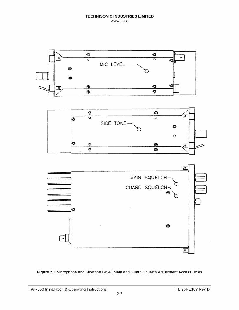
2.2.5 Transmitter Sidetone Level Adjustment
(1) Set the transceiver operating frequency to 156.000 MHz and connect an appropriate test receiver to the RF output connector. Ensure that the output of the transceiver is terminated into a proper dummy load.
(2) Key the transmitter and input a -10 dBm (0.25 VRMS), 1 kHz audio signal into the microphone input.
(3) Adjust the sidetone level potentiometer (R37 on MCU module) through the access hole located on the left side of the chassis (see Figure 2.3) to produce a +3.0 dBm (1.0 VRMS) 600 ohm audio output.
2.2.6 Main And Guard Squelch Adjustment
The squelch on both the main and guard receivers is factory set to open at approximately 0.5 microvolts. This adjustment can be made or altered to suit local conditions as follows:
(1) Set the main receiver of the transceiver to 156.0 MHz. Connect a signal generator the
antenna input of the transceiver.
(2) Set the signal generator to produce a ±3 kHz deviation with a 1 kHz tone on 156.000 MHz.Increase the signal generator RF level from 0.1 uV until the squelch indicator LED is on. Verify the receiver SINAD ratio is between 12 and 14 dB.
(3) If not, re-adjust main receiver squelch potentiometer, R3 through the access hole located on the bottom of the transceiver chassis (see Figure 2.3).
(4) Repeat the above procedure to adjust the guard receiver squelch setting using guard receiver squelch adjustment potentiometer, R4 (see Figure 2.3).
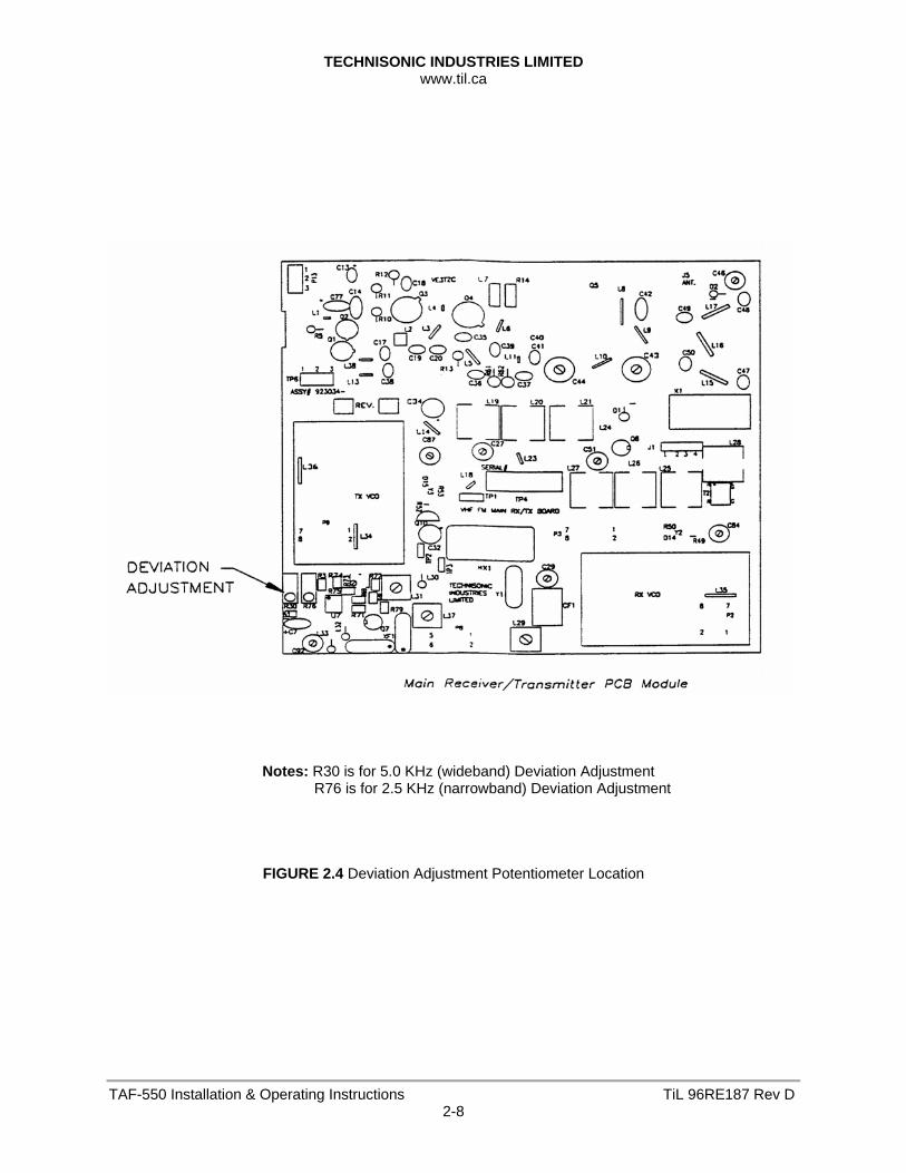
2.2.7 Transmitter Deviation Adjustment
(1) Remove and retain the eight (8) No. 4-40 screws securing the top cover of the transceiver to its chassis. You should now have access to the Main Rx/Tx Module.
(2) Set the transceiver operating frequency to 156.000 MHz and connect an appropriate test receiver to the RF output connector. Ensure that the output of the transceiver is terminated into a proper dummy load.
(3) Key the transmitter and input a +10 dBm (2.5 VRMS), 1 kHz audio signal into the microphone input.
(4) Adjust the wideband deviation limit potentiometer, R30 on the main Rx/Tx module (see Figure 2.4) to produce a ±4.45 kHz deviation. For TFM-138B only: Adjust the narrowband deviation limit potentiometer, R76 on the main Rx/Tx module to produce a ±2.2 kHz deviation. (All narrowband adjustments for TFM-138B only).
(5) Verify that the deviation does not exceed ±5 kHz for wideband and ±2.5 kHz for narrowband on the following frequencies: 138.000 MHz, 162.000 MHz and 174.000 MHz. Re-adjust R30 or R76 as required, if the deviation exceeds ±5 kHz or ±2.5 kHz, respectively.
(6) Place top cover on transceiver chassis and secure all eight (8) screws.
TECHNISONIC INDUSTRIES LIMITED www.til.ca
TAF-550 Installation & Operating Instructions TiL 96RE187 Rev D2-7
Figure 2.3 Microphone and Sidetone Level, Main and Guard Squelch Adjustment Access Holes
TECHNISONIC INDUSTRIES LIMITED www.til.ca
TAF-550 Installation & Operating Instructions TiL 96RE187 Rev D2-8
Notes: R30 is for 5.0 KHz (wideband) Deviation Adjustment R76 is for 2.5 KHz (narrowband) Deviation Adjustment
FIGURE 2.4 Deviation Adjustment Potentiometer Location
TECHNISONIC INDUSTRIES LIMITED www.til.ca
TAF-550 Installation & Operating Instructions TiL 96RE187 Rev D2-9
2.3 TiL-91-DE CUSTOM CONFIGURATION
Custom system configuration for the 91-DE Transceiver includes customizing channel frequencies. Channels 0 to 9 can be configured for fixed frequency operation including transmit inhibit on pre-selected channels.
2.3.1 Fixed Channel Frequency Set Up
The following procedure fixes pre-selected channel frequencies and inhibits transmit on receive only channels. After completion of this procedure the operator will be able select stored channels only for receive or transmit. Keypad entry of frequencies is disabled.
2.3.2 System Configuration
(1) Configure channel frequencies as desired (Refer to Section 3). (2) Select channels for Rx only (transmit inhibit) operation (Refer to 91-DE Keypad Operating
Instructions in Section 3). 2.3.3 Transceiver Removal
(1) Remove TAF-550 Modular Case Cover, the TFM-138B Transceiver then the 91-DE Transceiver. Refer to paragraph 2.1.1, 2.1.2 and 2.1.3.
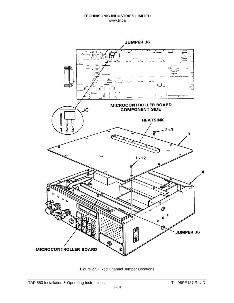
2.3.4 Transceiver Disassembly/Assembly and Jumper Installation
(1) Remove and retain 15 flathead screws securing transceiver top cover to chassis. Refer to Figure 2.5.
(2) Position Jumper J6 on pin 1 and pin 2 to disable keyboard entry of frequency selection and lock operating configuration.
(3) Position Jumper J6 on pin 2 and pin 3 to enable keypad frequency selection and unlock operating configuration.
(4) Position Transceiver Cover on Chassis. Ensure that cover holes are aligned with threaded inserts.
(5) Position 15 flathead screws through cover holes into chassis threaded inserts. Tighten screws with fingers. Tighten screws securing Transceiver Cover to Chassis.
2.3.5 Transceiver Replacement
(1) Replace 91-DE Transceiver into the TAF-550 Modular case by reversing the steps outlined in paragraphs 2.1.1, 2.1.2 and 2.1.3.
2.3.6 Operational Check
(1) Turn 91-DE Transceiver Unit On (Refer to Section 3).
(2) Recall Channels "0" through "9" (Refer to Section 3). Ensure that the frequencies indicated for each channel displayed correspond to those selected.
(3) Transmit on each channel. Observe that the TX Led (Refer to Figure 3-2, for location) does not light on channels selected to operate exclusively in receive mode.
(4) Enter a valid frequency (within the frequency range of (117.975 MHz to 138 MHz) that differs from the frequency stored in channel "0".
(5) Store the frequency in channel "0" (Refer to paragraph 3.4.5).
(6) Recall Channel "0" frequency. Channel "0" frequency displayed shall be the same frequency entered before Locking the operating configuration (ie. different from the frequency entered in step 4).
(7) Perform Steps 4 through 6 for each channel.
TECHNISONIC INDUSTRIES LIMITED www.til.ca
TAF-550 Installation & Operating Instructions TiL 96RE187 Rev D2-10
Figure 2.5 Fixed Channel Jumper Locations
TECHNISONIC INDUSTRIES LIMITED www.til.ca
TAF-550 Installation & Operating Instructions TiL 96RE187 Rev D3-1
SECTION 3 – OPERATING INSTRUCTIONS 3.1 INTRODUCTION
This section includes a functional description of each switch, control, indicator and connector located on the front and rear panels of the TAF-550 Modular Comm System, including the PRESS TO TALK switch located on the microphone. Specific Operating instructions for both the TFM-138B and TiL-91-DE Transceivers are also included.
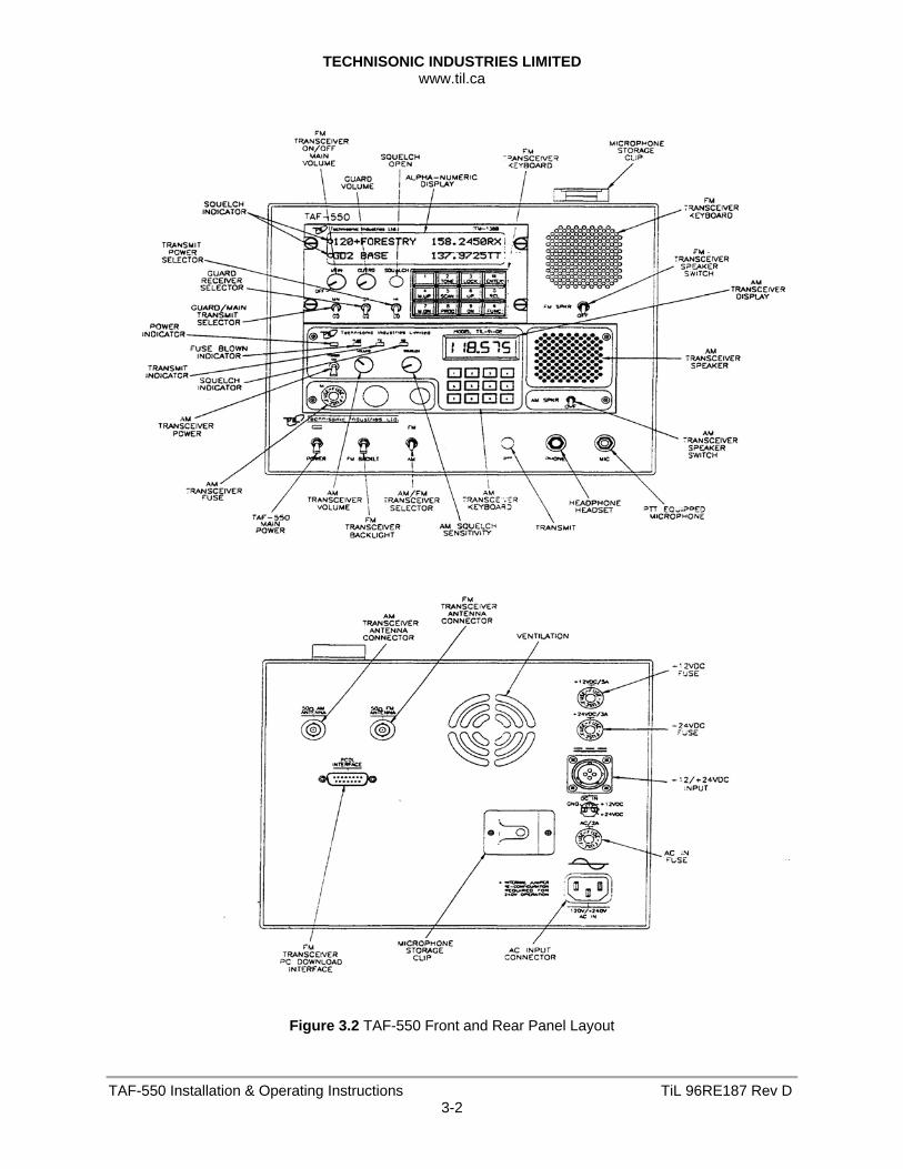
3.2 OPERATOR'S SWITCHES, CONTROLS AND INDICATORS
A view of the front and rear panel is given in Figure 3.2. A functional description of each of the operator's switches, controls and indicators, and the microphone PRESS TO TALK switch, is given in Table 3.1, Operator's Switches, Controls and Indicators and Table 3.2, Channel/Function Selector Keypad.
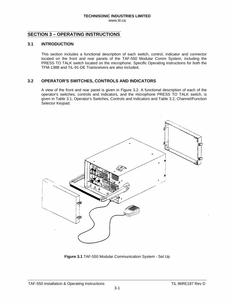
Figure 3.1 TAF-550 Modular Communication System - Set Up
TECHNISONIC INDUSTRIES LIMITED www.til.ca
TAF-550 Installation & Operating Instructions TiL 96RE187 Rev D3-2
Figure 3.2 TAF-550 Front and Rear Panel Layout
TECHNISONIC INDUSTRIES LIMITED www.til.ca
TAF-550 Installation & Operating Instructions TiL 96RE187 Rev D3-3
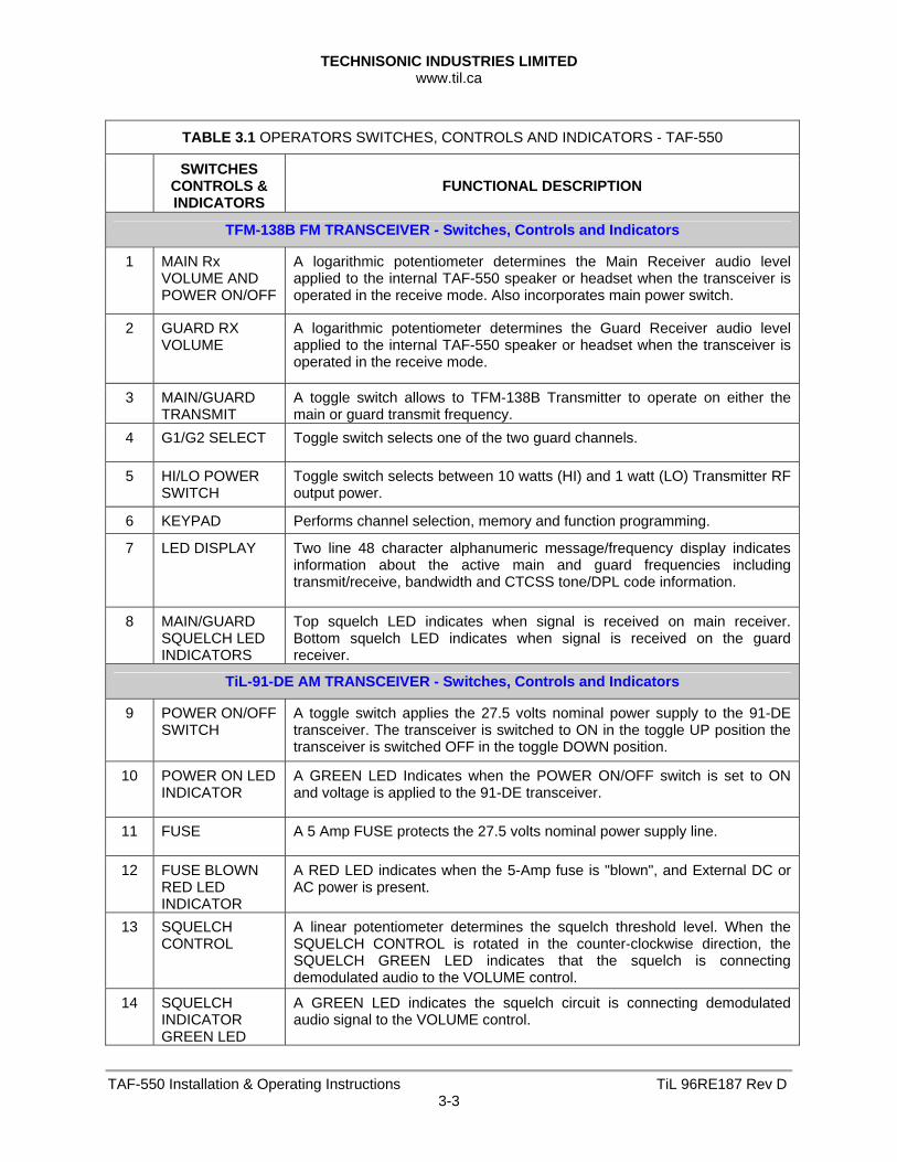
TABLE 3.1 OPERATORS SWITCHES, CONTROLS AND INDICATORS - TAF-550
SWITCHES CONTROLS & INDICATORS
FUNCTIONAL DESCRIPTION
TFM-138B FM TRANSCEIVER - Switches, Controls and Indicators
1 MAIN Rx VOLUME AND POWER ON/OFF
A logarithmic potentiometer determines the Main Receiver audio level applied to the internal TAF-550 speaker or headset when the transceiver is operated in the receive mode. Also incorporates main power switch.
2 GUARD RX VOLUME
A logarithmic potentiometer determines the Guard Receiver audio level applied to the internal TAF-550 speaker or headset when the transceiver is operated in the receive mode.
3 MAIN/GUARD TRANSMIT
A toggle switch allows to TFM-138B Transmitter to operate on either the main or guard transmit frequency.
4 G1/G2 SELECT Toggle switch selects one of the two guard channels.
5 HI/LO POWER SWITCH
Toggle switch selects between 10 watts (HI) and 1 watt (LO) Transmitter RF output power.
6 KEYPAD Performs channel selection, memory and function programming.
7 LED DISPLAY Two line 48 character alphanumeric message/frequency display indicates information about the active main and guard frequencies including transmit/receive, bandwidth and CTCSS tone/DPL code information.
8 MAIN/GUARD SQUELCH LED INDICATORS
Top squelch LED indicates when signal is received on main receiver. Bottom squelch LED indicates when signal is received on the guard receiver.
TiL-91-DE AM TRANSCEIVER - Switches, Controls and Indicators
9 POWER ON/OFF SWITCH
A toggle switch applies the 27.5 volts nominal power supply to the 91-DE transceiver. The transceiver is switched to ON in the toggle UP position the transceiver is switched OFF in the toggle DOWN position.
10 POWER ON LED INDICATOR
A GREEN LED Indicates when the POWER ON/OFF switch is set to ON and voltage is applied to the 91-DE transceiver.
11 FUSE A 5 Amp FUSE protects the 27.5 volts nominal power supply line.
12 FUSE BLOWN RED LED INDICATOR
A RED LED indicates when the 5-Amp fuse is "blown", and External DC or AC power is present.
13 SQUELCH CONTROL
A linear potentiometer determines the squelch threshold level. When the SQUELCH CONTROL is rotated in the counter-clockwise direction, the SQUELCH GREEN LED indicates that the squelch is connecting demodulated audio to the VOLUME control.
14 SQUELCH INDICATOR GREEN LED
A GREEN LED indicates the squelch circuit is connecting demodulated audio signal to the VOLUME control.
TECHNISONIC INDUSTRIES LIMITED www.til.ca
TAF-550 Installation & Operating Instructions TiL 96RE187 Rev D3-4
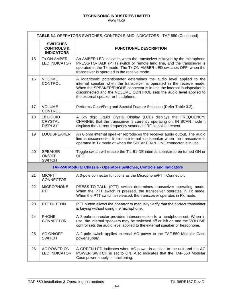
TABLE 3.1 OPERATORS SWITCHES, CONTROLS AND INDICATORS - TAF-550 (Continued)
SWITCHES CONTROLS & INDICATORS
FUNCTIONAL DESCRIPTION
15 Tx ON AMBER LED INDICATOR
An AMBER LED indicates when the transceiver is keyed by the microphone PRESS-TO-TALK (PTT) switch or remote land line, and the transceiver is operated in the Tx mode. The Tx ON AMBER LED switches OFF, when the transceiver is operated in the receive mode.
16 VOLUME CONTROL
A logarithmic potentiometer determines the audio level applied to the internal speaker when the transceiver is operated in the receive mode. When the SPEAKER/PHONE connector is in use the internal loudspeaker is disconnected and the VOLUME CONTROL sets the audio level applied to the external speaker or headphone.
17 VOLUME CONTROL
Performs Chan/Freq and Special Feature Selection (Refer Table 3.2).
18 18 LIQUID CRYSTAL DISPLAY
A 5½ digit Liquid Crystal Display (LCD) displays the FREQUENCY/ CHANNEL that the transceiver is currently operating on. IN SCAN mode it displays the current frequency scanned if RF signal is present.
19 LOUDSPEAKER An 8-ohm internal speaker reproduces the receiver audio output. The audio line is disconnected from the internal loudspeaker when the transceiver is operated in Tx mode or when the SPEAKER/PHONE connector is in use.
20 SPEAKER ON/OFF SWITCH
Toggle switch will enable the TiL-91-DE internal speaker to be turned ON or OFF.
TAF-550 Modular Chassis - Operators Switches, Controls and Indicators
21 MIC/PTT CONNECTOR
A 3-pole connector functions as the Microphone/PTT Connector.
22 MICROPHONE PTT
PRESS-TO-TALK (PTT) switch determines transceiver operating mode. When the PTT switch is pressed, the transceiver operates in Tx mode. When the PTT switch is released, the transceiver operates in Rx mode.
23 PTT BUTTON PTT button allows the operator to manually verify that the correct transmitter is keying without using the microphone.
24 PHONE CONNECTOR
A 3-pole connector provides interconnection to a headphone set. When in use, the internal speakers may be switched off or left on and the VOLUME control sets the audio level applied to the external speaker or headphone.
25 AC ON/OFF SWITCH
A 2-pole switch applies external AC power to the TAF-550 Modular Case power supply.
26 AC POWER ON LED INDICATOR
A GREEN LED indicates when AC power is applied to the unit and the AC POWER SWITCH is set to ON. Also indicates that the TAF-550 Modular Case power supply is functioning.
TECHNISONIC INDUSTRIES LIMITED www.til.ca
TAF-550 Installation & Operating Instructions TiL 96RE187 Rev D3-5
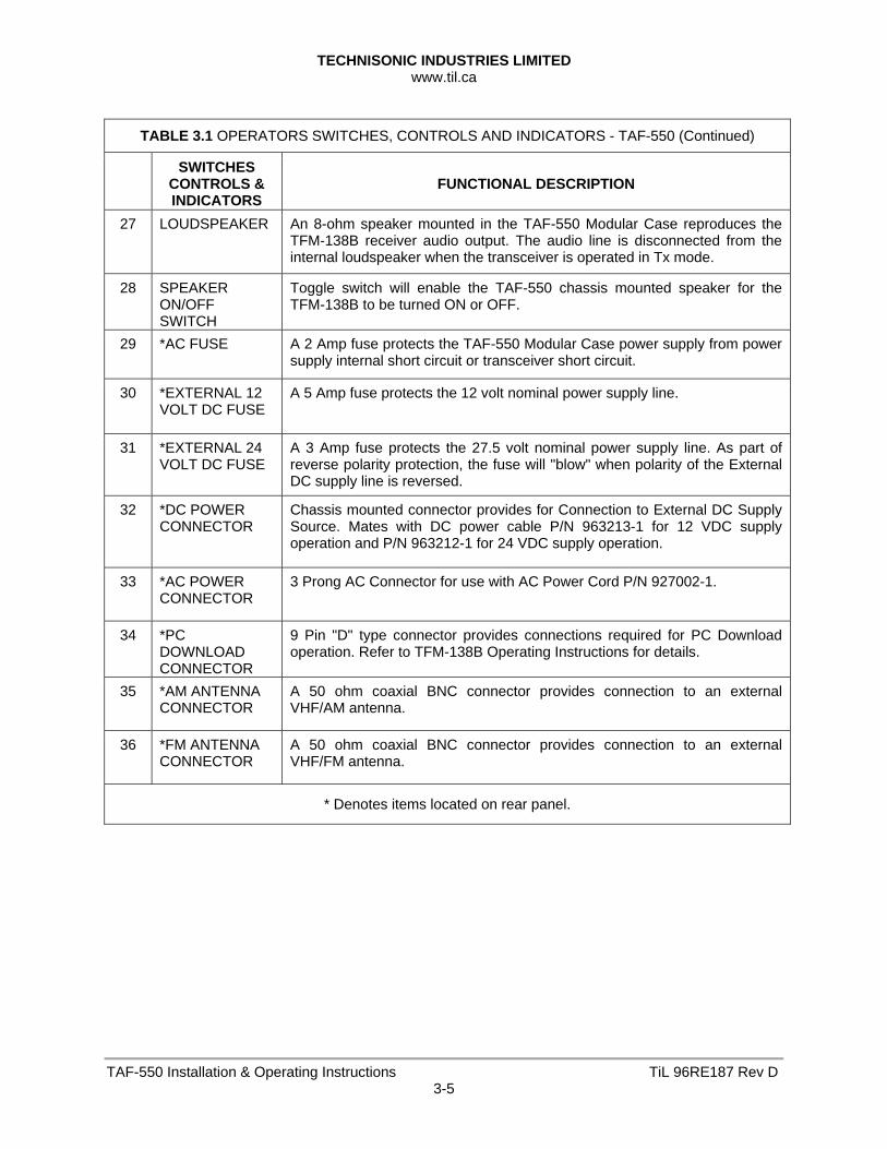
TABLE 3.1 OPERATORS SWITCHES, CONTROLS AND INDICATORS - TAF-550 (Continued)
SWITCHES CONTROLS & INDICATORS
FUNCTIONAL DESCRIPTION
27 LOUDSPEAKER An 8-ohm speaker mounted in the TAF-550 Modular Case reproduces the TFM-138B receiver audio output. The audio line is disconnected from the internal loudspeaker when the transceiver is operated in Tx mode.
28 SPEAKER ON/OFF SWITCH
Toggle switch will enable the TAF-550 chassis mounted speaker for the TFM-138B to be turned ON or OFF.
29 *AC FUSE A 2 Amp fuse protects the TAF-550 Modular Case power supply from power supply internal short circuit or transceiver short circuit.
30 *EXTERNAL 12 VOLT DC FUSE
A 5 Amp fuse protects the 12 volt nominal power supply line.
31 *EXTERNAL 24 VOLT DC FUSE
A 3 Amp fuse protects the 27.5 volt nominal power supply line. As part of reverse polarity protection, the fuse will "blow" when polarity of the External DC supply line is reversed.
32 *DC POWER CONNECTOR
Chassis mounted connector provides for Connection to External DC Supply Source. Mates with DC power cable P/N 963213-1 for 12 VDC supply operation and P/N 963212-1 for 24 VDC supply operation.
33 *AC POWER CONNECTOR
3 Prong AC Connector for use with AC Power Cord P/N 927002-1.
34 *PC DOWNLOAD CONNECTOR
9 Pin "D" type connector provides connections required for PC Download operation. Refer to TFM-138B Operating Instructions for details.
35 *AM ANTENNA CONNECTOR
A 50 ohm coaxial BNC connector provides connection to an external VHF/AM antenna.
36 *FM ANTENNA CONNECTOR
A 50 ohm coaxial BNC connector provides connection to an external VHF/FM antenna.
* Denotes items located on rear panel.
TECHNISONIC INDUSTRIES LIMITED www.til.ca
TAF-550 Installation & Operating Instructions TiL 96RE187 Rev D3-6
3.3 GENERAL OPERATING INSTRUCTIONS 3.3.1 Preparation for Use
To prepare the transceiver for use (Refer to Figures 3.1, 3.2 and Table 3.1). (1) Location of Antennae
The VHF frequency band is essentially line of site communication. When selecting a location there should be no obstacles between the communicating radio sites. Objects greater than two metres will reflect the RF signal and foliage greatly attenuates signal strength. The VHF/AM and VHF/FM antennae should be positioned as far apart as space permits for optimum performance. The mounting height of each antenna should also be maximized. The antennae should be separated by a minimum distance of at least 15 feet.
WARNING
Do not make physical contact with antenna when transmitter is on. This unit can produce up to 10 Watts of power when operated in High Power Mode.
(2) Open front and rear access covers by levering the clip fasteners toward front of case.
Remove Microphone from its storage clip on the rear panel and install jack in Microphone (PTT) connector. A clip to mount the microphone when connected for use is provided on the top right hand side of the TAF-550 Modular case.
(3) Ensure that TFM-138B and 91-DE transceiver POWER knob/switch are set to OFF.
(4) Remove AC Cord from rear access cover and install in AC chassis connector on rear panel or install External DC Cable in External DC chassis connector on rear panel as required. Caution: Make certain to use the appropriate DC Cable for either 12V or 24V DC operation. The 12VDC cable connects to pin 1 (12V input) and pin 2 (ground) of the DC mating connector located on the rear of the TAF-550 case. The 24 VDC cable connects to pin 3 (24V input) and pin 2 (ground) of the DC mating connector.
(5) Install the appropriate antennae and cables to the rear panel chassis BNC connectors for AM and FM use. Adjust Antenna location to maximize distance, height and vertical polarization.
(6) Select Main Power switch to the ON position. Verify the GREEN LED located above this switch illuminates.
(7) Remove the microphone from the front microphone mounting clip, and ensure that the microphone connector is connected to the MIC/PTT connector on the TAF-550.
(8) If desired connect a headphone to the front panel PHONE connector on the TAF-550.
(9) Use the FM/AM selector switch on the front panel of the TAF-550 chassis to select the Transceiver for which the microphone transmit and headphone receive operations will be routed to.
(10) Turn the FM Transceiver and/or AM Transceiver speaker ON or OFF as desired using the ON/OFF selector switch located under each speaker.
(11) For the 91-DE set the SQUELCH control in the fully counter-clockwise (CCW) position.
(12) Set the VOLUME control as desired on both Transceivers.
(13) Refer to Paragraphs 3.4 and 3.5 of this Manual for Operating Instructions specific to the TFM-138B or 91-DE Transceivers.
TECHNISONIC INDUSTRIES LIMITED www.til.ca
TAF-550 Installation & Operating Instructions TiL 96RE187 Rev D3-7
3.3.2 Transmitter Operation
To operate either transceiver in the transmit mode select appropriate position of the FM/AM selector switch and proceed as follows: (1) Set HI/LO (10W/1W) RF POWER switch to desired operating level on TFM-138B.
(2) Hold the microphone in one hand, with the upper edge of the microphone as close as Possible to the upper lip.
NOTE
This technique activates the noise cancelling feature of the microphone. The microphone is most effective when sound is ½ inch (12.7 mm) or more away from the microphone.
(3) Press and hold the PRESS TO TALK switch of the microphone during transmission.
(4) Ensure that the Tx ON amber LED is ON, on the 91-DE front panel or that the alphanumeric display on the main or guard (as selected) indicates “TX” or “TT” on the TFM-138B. “TT” indicates a transmit CTCSS tone or DPL code has been programmed.
(5) Speak slowly and distinctly into the microphone using specified operating procedures during transmission.
(6) When message is ended, release the PRESS TO TALK switch of the microphone.
(7) The transceiver is now operating in the receive mode.
(8) Verify that the Tx ON amber LED is OFF on the 91-DE or that “RX” or “RT” is indicated rather than “TX” or “TT” on the alphanumeric display of the TFM-138B.
(9) Refer to paragraph 3.4 for 91-DE Front Panel Keypad Operation and additional Operating modes. Refer to paragraph 3.5 for completeTFM-138B operating instructions.
TECHNISONIC INDUSTRIES LIMITED www.til.ca
TAF-550 Installation & Operating Instructions TiL 96RE187 Rev D3-8
3.3.3 Receiver Operation
To operate either transceiver in the receive mode, proceed as follows: (1) Ensure that the PRESS TO TALK switch on the microphone is NOT depressed, and
verify that the Tx ON amber LED is OFF on the 91-DE or that the alphanumeric display on the TFM-138B does not indicate “TX” or “TT”.
(2) Verify that the correct operating frequency is displayed on the liquid crystal display (LCD) on the 91-DE or the alphanumeric LED display on the TFM-138B. Refer to Front Panel Keypad Operation, paragraph 3.4 for Channel/Frequency selection on the 91-DE. Refer to paragraph
(3) Adjust the SQUELCH control to suit local reception conditions. When the SQUELCH control is rotated in the counter-clockwise direction, the SQUELCH indicator green LED will switch to ON, indicating that the squelch circuit is connecting the demodulated audio output to the VOLUME control.
Further adjustment of the SQUELCH control determines the squelch setting.
(4) The VOLUME control can then be adjusted in a clockwise direction to increase the audio level, or in a counter-clockwise direction to decrease the audio level which can be heard on the internal loudspeaker.
NOTE
When an external loudspeaker or headset is connected to the SPEAKER/PHONE jack of the transceiver, the internal loudspeaker is automatically disconnected. The VOLUME control will now control the audio level applied to the external loudspeaker or headset, as applicable.
(5) Refer to paragraph 3.4 for Front Panel Keypad Operation and additional Operating modes.
3.3.4 Switching OFF To switch off the transceiver:
(1) Set the POWER ON/OFF on transceiver to switch to OFF.
(2) Verify that all indicator LED's on the front panel are OFF.
TECHNISONIC INDUSTRIES LIMITED www.til.ca
TAF-550 Installation & Operating Instructions TiL 96RE187 Rev D3-9
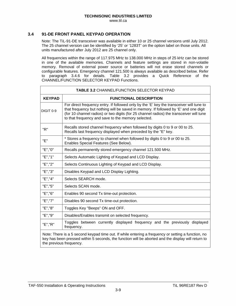
3.4 91-DE FRONT PANEL KEYPAD OPERATION
Note: The TiL-91-DE transceiver was available in either 10 or 25 channel versions until July 2012. The 25 channel version can be identified by ‘25’ or ‘1283T’ on the option label on those units. All units manufactured after July 2012 are 25 channel only. All frequencies within the range of 117.975 MHz to 138.000 MHz in steps of 25 kHz can be stored in one of the available memories. Channels and feature settings are stored in non-volatile memory. Removal of external power source or batteries will not erase stored channels or configurable features. Emergency channel 121.500 is always available as described below. Refer to paragraph 3.4.6 for details. Table 3.2 provides a Quick Reference of the CHANNEL/FUNCTION SELECTOR KEYPAD Functions.
TABLE 3.2 CHANNEL/FUNCTION SELECTOR KEYPAD
KEYPAD FUNCTIONAL DESCRIPTION
DIGIT 0-9
For direct frequency entry. If followed only by the ‘E’ key the transceiver will tune to that frequency but nothing will be saved in memory. If followed by ‘E’ and one digit (for 10 channel radios) or two digits (for 25 channel radios) the transceiver will tune to that frequency and save to the memory selected.
"R" Recalls stored channel frequency when followed by digits 0 to 9 or 00 to 25. Recalls last frequency displayed when preceded by the "E" key.
"E" * Stores a frequency to channel when followed by digits 0 to 9 or 00 to 25. Enables Special Features (See Below).
"E","0" Recalls permanently stored emergency channel 121.500 MHz.
"E","1" Selects Automatic Lighting of Keypad and LCD Display.
"E","2" Selects Continuous Lighting of Keypad and LCD Display.
"E","3" Disables Keypad and LCD Display Lighting.
"E","4" Selects SEARCH mode.
"E","5" Selects SCAN mode.
"E","6" Enables 90 second Tx time-out protection.
"E","7" Disables 90 second Tx time-out protection.
"E","8" Toggles Key "Beeps" ON and OFF.
"E","9" Disables/Enables transmit on selected frequency.
"E","R" Toggles between currently displayed frequency and the previously displayed frequency.
Note: There is a 5 second keypad time out. If while entering a frequency or setting a function, no key has been pressed within 5 seconds, the function will be aborted and the display will return to the previous frequency.
TECHNISONIC INDUSTRIES LIMITED www.til.ca
TAF-550 Installation & Operating Instructions TiL 96RE187 Rev D3-10
3.4.1 Keypad "Beeps"
Audible "Beeps" are generated when a key is pressed (default condition). Beeps can be enabled/disabled by toggling the "E","8" keys.
Press , to disable Key "Beeps".
Press , to enable Key "Beeps".
3.4.2 Keypad and LCD Display Lighting
Three Display and keypad lighting modes are available to the operator. The default mode provides no keypad or LCD display backlighting. In Continuous mode, display backlight and keypad lighting is permanent until power is removed or until lighting mode exited. In automatic mode, display backlight and keypad lighting is off until a key on the keypad is pressed or until the lighting mode is exited.
Press to initiate automatic lighting.
Press to initiate continuous lighting.
Press to turn to lighting OFF.
3.4.3 Transmitter Time-out
A 90 second time-out timer is provided to prevent accidental continuous transmission.
Press to initiate 90 second Tx time-out protection.
Press to disable 90 second Tx time-out protection.
TECHNISONIC INDUSTRIES LIMITED www.til.ca
TAF-550 Installation & Operating Instructions TiL 96RE187 Rev D3-11
3.4.4 Selecting a Frequency
To select a frequency, press the keypad digits in the sequence indicated (Refer to Fig 3.2 Base Station Front and Rear Panel Layout, and Table 3.1 Operators Switches Controls and Indicators).
1st digit - must be 1 for 100 MHz, all other digits are ignored. 2nd digit - must be 1, 2 or 3, all other digits are ignored.
NOTE
Entry of 117 MHz fills 975 in remaining digits. Entry of 138 MHz fills 000 in remaining digits.
4th digit - Can be any digit. 5th + 6th digits are paired.
Entry of 5th digit 0 results in 00 displayed. Entry of 2 results in 25. Entry of 5 results in 50. Entry of 7 results in 75.
Examples:
Press 117.975 is displayed on screen. Press 118.000 is displayed on screen.
Press 138.000 is displayed on screen.
After keypad entry of a desired frequency, normal Tx/Rx operation can begin or the frequency can be stored as a channel as described in paragraph 3.4.5 (Storing a Frequency to a Channel).
TECHNISONIC INDUSTRIES LIMITED www.til.ca
TAF-550 Installation & Operating Instructions TiL 96RE187 Rev D3-12
3.4.5 Storing a Frequency to a Channel
Up to 10 Frequencies can be stored and recalled in channels 0 to 9 as follows or , up to 25 Frequencies can be stored and recalled in channels 01 to 25 as follows: (1) Enter the frequency to be stored as described in paragraph 3.4.4 (Selecting a Frequency)
followed immediately by pressing "E" and the desired Channel number “#” or "##" (for 25 channels).
NOTE "E",”#” or “E”, "##" (for 25 channels) must be pressed within 5 seconds of entry or frequency will not be stored.
Examples:
Radios with 10 channels Radios with 25 channels
Press Frequency 117.975 MHz is stored as channel 0.
Press Frequency 119.750 MHz is stored as channel 1.
Press 138.000 MHz as channel 2.
Press Frequency 117.975 MHz is stored as channel 00.
Press Frequency 119.750 MHz is stored as channel 01.
Press 138.000 MHz as channel 02.
3.4.6 Recalling a Stored Channel
To recall one of the previously stored channels, press"R" followed by the channel number. Example:
Radios with 10 channels Radios with 25 channels
Channel 1 frequency 119.750 MHz stored in the previous example will be displayed.
Press
Channel 01 frequency 119.750 MHz stored in the previous example will be displayed.
Press Note: To recall the permanently stored emergency channel 121.500 MHz, press"E","0".
TECHNISONIC INDUSTRIES LIMITED www.til.ca
TAF-550 Installation & Operating Instructions TiL 96RE187 Rev D3-13
3.4.7 Transmit Inhibit
To Inhibit the transmit function on a desired channel press "E","9" immediately followed by the channel "#" or “##” to be inhibited. Subsequent pressing of "E","9","#" or "E","9","##" will enable the transmit function.
NOTE
After inhibiting the transmit function, the Tx inhibited channel must be recalled from memory for this function to take effect.
Examples:
Press or Press (for 25 channels) Channel 1 frequency 119.750 MHz stored in the previous example will be displayed. Press the PRESS-TO-TALK switch. Observe that the TX indicator LED lights.
Press Press or
Press Press (for 25 channels) Press the PRESS-TO-TALK switch. Observe that the TX indicator LED does not light.
Press Press or
Press Press (for 25 channels) Press the PRESS-TO-TALK switch. Observe that the TX indicator LED lights.
3.4.8 Toggling Between Two Channels
Press to recall previous channel.
Example: Recall Channel 0 as described in para. 3.4.6 (Recalling a Stored Channel). 117.975 will be displayed. Recall Channel 2 138.000 will be displayed.
Press 117.975 will be displayed.
Press 138.000 will be displayed.
TECHNISONIC INDUSTRIES LIMITED www.til.ca
TAF-550 Installation & Operating Instructions TiL 96RE187 Rev D3-14
3.4.9 Search Mode
In SEARCH MODE the receiver steps through each stored channel until a transmitted signal is found. The receiver will lock on to the first signal strong enough to quiet the squelch circuit. SEARCH mode is exited when a signal is found. Normal operation resumes as if the SEARCH frequency was selected from the keypad or recalled from memory.
Press to enter SEARCH mode.
Press to exit SEARCH mode. 3.4.10 Scan Mode
In SCAN MODE the receiver steps through each stored channel until a transmitted signal is found. The receiver will lock on to the first signal strong enough to quiet the squelch circuit. When a signal is found, the frequency is displayed and the audio is enabled for as long as the squelch is held open by the RF signal. After the signal drops below the squelch threshold SCAN is resumed until the next frequency is found and the process is repeated. SCAN mode is continuous until the operator exits or the unit is switched off.
NOTE PTT is inhibited during SCAN mode. Pressing PTT once exits SCAN mode. Pressing PTT twice is required to Key the Transmitter.
Press to enter SCAN mode. Press PTT to Lock on SCANned Frequency or
Press to exit SCAN.
TECHNISONIC INDUSTRIES LIMITED www.til.ca
TAF-550 Installation & Operating Instructions TiL 96RE187 Rev D3-15
3.5 TFM-138B OPERATING FEATURES
The TFM-138B has several important operating features which include: 1. 120 memory positions which can each be programmed with a transmit and receive
frequency with 25 or 12.5 kHz channel spacing, Tx/Rx CTCSS tones or DPL codes and a 9-character alphanumeric title.
2. 2 guard channels which can each be programmed with a Rx frequency with 25 or 12.5 kHz channel spacing, CTCSS Tx tone or DPL code and a 9-character alphanumeric title.
3. Scanning of preprogrammed memories with selective memory scanning.
4. Priority scan of memory channel 1, if desired.
5. Direct frequency entry mode.
6. Receive frequency simplex function.
7. Switchable RF output power between 1 watt and 8-10 watts.
8. Lockout of keyboard to prevent inadvertent entries.
9. Variable frequency mode to manually scan up and down in 2.5 kHz steps.
10. LED display variable dimming mode.
11. Selectable 90 second Tx time out feature.
12. Quick download of any of the 120 memory positions to the guard memories.
13. PC Memory download capability.
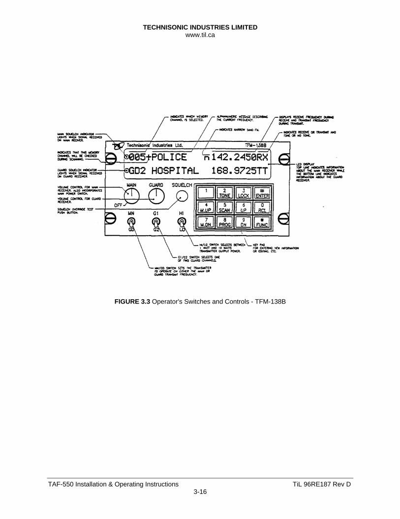
3.5.1 OPERATING INSTRUCTIONS (See Figure 3.3)
1. Switch power on by turning the main volume clockwise. The last programmed frequencies will be displayed. The transceiver is now in normal operating mode.
2. Adjust the audio level by adjusting the main and guard volume knobs.
3. Pressing the squelch defeat button will open both receivers to confirm they work.
4. Read the display. The top line will indicate which memory is selected followed by a "+" if the memory position is included in the scan list, an alpha-numeric message, and the frequency of the main receiver. A small "n" before the frequency indicates 12.5 kHz narrowband channel spacing is in effect on this memory position. In the receive mode, the frequency is followed by an "RT" if a RX CTCSS tone or RX DPL code is programmed, or an "RX" if no Receive tone/code is programmed. Similarity in the transmit mode either a "TT" or "TX" is shown after the frequency. The bottom line indicates similar information about the guard receiver.
5. Only TX CTCSS tones or TX DPL codes may be programmed for the guard receiver. At the beginning of each line, an LED indicates open squelch.
TECHNISONIC INDUSTRIES LIMITED www.til.ca
TAF-550 Installation & Operating Instructions TiL 96RE187 Rev D3-16
FIGURE 3.3 Operator's Switches and Controls - TFM-138B
TECHNISONIC INDUSTRIES LIMITED www.til.ca
TAF-550 Installation & Operating Instructions TiL 96RE187 Rev D3-17
3.5.1 OPERATING INSTRUCTIONS - continued
6. Set the MN/GD switch to main or guard transmit frequency.
7. Set the G1/G2 switch to the desired guard channel.
8. Set the HI/LO switch to the desired RF output power.
9. Select the desired memory by using the M.UP and M.DN buttons, or the RCL button and a three digit number followed by ENTER.
10. To transmit DTMF tones, use the keyboard keys while holding the PTT button on the microphone. The keyboard returns to its normal function when the PTT is released.
The display always shows the status of both receivers and the transmitter. The light at the left of the top and bottom line indicates which receiver is receiving. The display also indicates the memory channel in use and the guard channel in use. A "TX" (no TX tone/codes programmed) or "TT"(either TX tone or code programmed) on the right side of the display indicates whether the guard or main channel is active when transmitting. The transmit frequency is also shown. In the receive mode the display shows “RX” beside the receive frequency, if no RX tone or DPL code is programmed and “RT”, if a CTCSS tone or DPL code is programmed. When the transceiver is in either of the operating frequency or CTCSS tone/DPL code programming modes and you must respond to a call, click the microphone PTT once (the radio will not transmit during this click). This will cause the transceiver to revert back to the normal operating mode and communications with the caller can proceed in the usual fashion.
3.5.2 PROGRAMMING INSTRUCTIONS
To program one of the 120 memory channels in the TFM-138B: 1. Press the FUNC key. The display will show the function prompt.
2. Press the PROG key. The display will show the current receive frequency with a flashing curser on the second digit (The first digit is always a one <1>).
3. Type in the desired receive frequency. If you type in a frequency which is not a 2.5 kHz step, the nearest valid frequency will be automatically selected.
4. The curser will return to the second digit. You can now retype the frequency if you made an error or press ENTER to continue.
5. The transmit frequency will be displayed with the curser on the second digit. Follow the same method as in step 3 and 4.
6. The channel spacing increment of either 25.0 or 12.5 KHz is now displayed. Use the M.UP and M.DN keys to select the desired channel spacing for the memory position, then press ENTER.
7. The alpha-numeric title is now displayed. Use the M.UP and M.DN keys to scroll through the alphabet, numbers and symbols. When the desired character is displayed, press ENTER to advance to the next character.
8. Keep repeating step six until the last space is set. The display will show SCAN or LOCKOUT to enable this memory position as part of the scan list or lock it out of the scan list. Use the M.UP and M.DN keys to toggle between these functions (for details see paragraph 3.5.4). Once the desired condition has been selected, press ENTER. The display will show a "+" beside the memory channel number if scan is enabled.
TECHNISONIC INDUSTRIES LIMITED www.til.ca
TAF-550 Installation & Operating Instructions TiL 96RE187 Rev D3-18
3.5.2 PROGRAMMING INSTRUCTIONS - continued
9. The display will now show the current memory number. Type in the 3-digit number of the
memory you want to save to (if different from displayed one) and press ENTER.
10. You now have the option to program the guard frequencies by pressing FUNC or press ENTER to return to normal operating mode.
11. If you pressed FUNC to program the guards, guard"1" transmit frequency will be displayed with the flashing curser on the second digit. Enter the frequencies for guard"1" receive/transmit and guard"2" receive/transmit as in step 3 and 4.
12. The alphanumeric labels for guard"1" and guard"2" are entered the same as in step 7 and 8. When the last character is entered, the radio returns to normal operating mode. If the guard is be programmed for 12.5 kHz narrowband operation, use the QUICK GUARD PROGRAMMING FEATURE described in paragraph 3.5.11.A memory position must be programmed to the 12.5 kHz mode then the contents can be quickly downloaded to GD1 or GD2 memory positions.
Programming of memory is disabled when the internal entry disable jumper is set. Alternatively any transceiver can be programmed by an IBM PC or compatible computer. See section 3.5.13 PC Memory/Programming Download Capability.
3.5.3 SCANNING FUNCTION (5 second talkback delay)
1. To start scanning of the memory channels, press FUNC then SCAN. The radio will scan through all the preset memory positions (see next paragraph for priority and selective scan features) and will lock on to the first active channel in the scan sequence. It will remain on the channel until it becomes inactive. Scanning will resume again after five seconds of inactivity. To exit the scan mode, press the SCAN key. This will cause the radio to revert back to the normal operating mode. Therefore if while scanning, you hear a call for you: 1. Respond to the call within 5 seconds. When scanning is interrupted by an incoming
signal, the channel will remain open for five seconds before resuming scanning.
2. During communications the five second timer is reset from the last Rx or Tx signal experienced.
The radio resumes scanning once the Rx or Tx activity has ceased for more than five seconds. The SCAN key must be pressed to exit the scan mode.
TECHNISONIC INDUSTRIES LIMITED www.til.ca
TAF-550 Installation & Operating Instructions TiL 96RE187 Rev D3-19
3.5.4 PRIORITY AND SELECTIVE MEMORY CHANNEL SCANNING
The priority memory channel is always memory position number 1. The priority memory channel is scanned every other step (i.e. 121314151) to ensure that no incoming messages are missed. The priority channel can be locked out, which will result in the normal scanning of the other memory positions. Selective memory scanning allows the user to select which of the 120 memory channels are to be scanned or locked out when the scan function is invoked. To use this feature, follow the PROGRAMMING INSTRUCTIONS found in paragraph 2.3. Once the screen displays SCAN or LOCKOUT, use the M.UP or M.DN keys to toggle to the desired condition and press ENTER. In normal operating mode the display (of the TFM-138B) will later show a "+" beside the memory channel number if scan is enabled.
3.5.5 DIRECT FREQUENCY ENTRY MODE
This mode is designed to facilitate quick frequency selection during emergency and other operational conditions requiring direct operating frequency selection. This operating mode is disabled along with the programming mode when the internal disable jumper is set. 1. When the transceiver is in the normal operating mode, press FUNC and the desired
operating frequency i.e. 153.275. Please note in the above operation, after FUNC and "1" are entered, the LED display will show memory channel "000" and then the remaining digits in the desired frequency are shown as they are entered. No alphanumeric message can be entered in this mode. Operation on the new frequency occurs in both transmit and receive (simplex only) modes. If RX or TX CTCSS tones/DPL codes are required they must be programmed on.
3.5.6 RECEIVE FREQUENCY SIMPLEX FUNCTION
The receive frequency simplex function allows you to quickly change the transmit frequency, when operating on a split pair (repeater/semi-duplex mode), to the receive frequency to allow direct communications. i.e. If you are transmitting on 152.000 MHz and receiving 152.555 MHz, press FUNC then UP to transmit on 152.555 MHz. To return to the split pair condition, you must recall the memory channel again. This is quickly done by pressing M.UP for one step up, then back down one step with the M.DN key.
3.5.7 KEYBOARD LOCKOUT FUNCTION
The keyboard can be locked out so that accidental pressing of keys does not change frequency, etc., unknowingly to the operator. To lock the keyboard, press FUNC then LOCK. This will disable all keyboard functions (except keyboard unlock) in the receive mode. The DTMF function during transmit will not be affected. To unlock the keyboard, press and hold the LOCK key for two seconds until the display indicates "UNLOCK".
TECHNISONIC INDUSTRIES LIMITED www.til.ca
TAF-550 Installation & Operating Instructions TiL 96RE187 Rev D3-20
3.5.8 Variable Frequency Mode Function
To enter variable frequency mode, press RCL, 0,0,0, then ENTER. The memory channel that you were just in will still be valid but now you can manually adjust the frequency with the M.UP, M.DN, UP and DN keys. The UP and DN keys will make the frequency count up or down in steps of 2.5 kHz. The M.UP and M.DN keys will make the frequency count up or down in steps of 1 MHz. You can not change the label. The frequency in this mode can not be stored in memory. To exit this mode, recall one of the 120 memory channels (ie. RCL, 0,0,1). Variable frequency mode is disabled when the internal entry disable jumper is set.
3.5.9 Led Display Variable Dimming Mode
1. With the transceiver in normal operating mode press the UP or DN keys to increase or decrease the intensity of the LED display.
2. Once maximum intensity of the display is achieved, the UP key no longer functions. Conversely once minimum intensity is reached, the DN key ceases to function.
3.5.10 90 Second Transmitter Time Out Feature
A selectable 90 second transmitter time out feature is provided to prevent accidental continuous transmission in the event of a faulty PTT switch. With this feature enabled the transceiver will stop transmitting after the PTT is engaged continuously for 90 seconds. The timer is reset by releasing then re-engaging the PTT switch. Press the FUNC then the M.UP key. Use the M.UP and M.DN keys to select 90 SEC, which enables the feature, or NONE which disables it.
3.5.11 Quick Guard Programming Feature
A quick download of any of the 120 memory positions to either of the guard memory positions can be accomplished. Select the memory position whose contents you desire to download to a guard memory. Select either GD1 or GD2 memory channel as desired. Press FUNC then 7. The guard memory channel will now contain all the same information as the selected memory position.
3.5.12 Programming CTCSS Tones/DPL Codes
NOTE: The TFM-138B supports both CTCSS tone and DPL code functions. CTCSS tones (PL tones) or Digital DPL codes can be assigned to each memory channel. The guard receiver squelch will operate only on carrier detection, but guard 1 and 2 transmit tones or codes can be programmed. To program a tone/code to a memory channel: 1. Use the M.UP and M.DN keys to select the memory channel that you want to assign a
CTCSS tone or DPL code.
2. Press the FUNC key then the TONE key. The display will show "RX TONE:" and the current tone number, as well as the tone frequency in Hz.
3. Use the M.UP and M.DN keys to select the tone number you require. The following is a list of the available CTCSS tones:
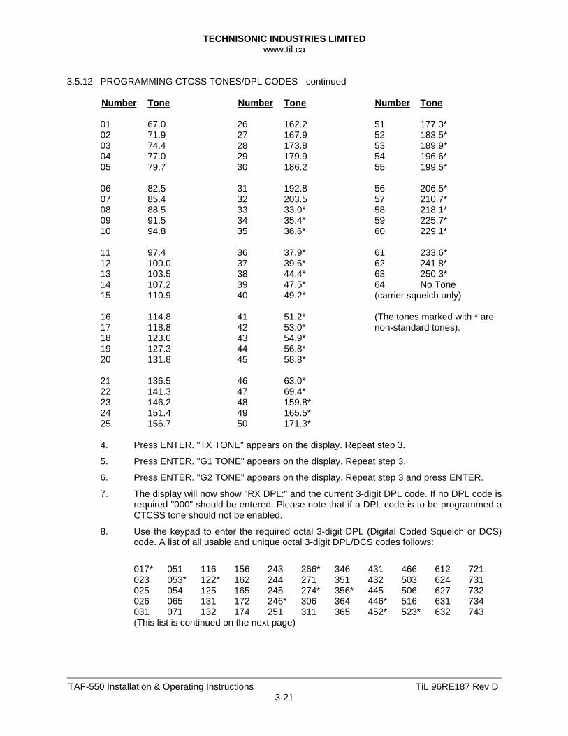
TECHNISONIC INDUSTRIES LIMITED www.til.ca
TAF-550 Installation & Operating Instructions TiL 96RE187 Rev D3-21
3.5.12 PROGRAMMING CTCSS TONES/DPL CODES - continued
Number Tone Number Tone Number Tone 01 67.0 26 162.2 51 177.3* 02 71.9 27 167.9 52 183.5* 03 74.4 28 173.8 53 189.9* 04 77.0 29 179.9 54 196.6* 05 79.7 30 186.2 55 199.5* 06 82.5 31 192.8 56 206.5* 07 85.4 32 203.5 57 210.7* 08 88.5 33 33.0* 58 218.1* 09 91.5 34 35.4* 59 225.7* 10 94.8 35 36.6* 60 229.1* 11 97.4 36 37.9* 61 233.6* 12 100.0 37 39.6* 62 241.8* 13 103.5 38 44.4* 63 250.3* 14 107.2 39 47.5* 64 No Tone 15 110.9 40 49.2* (carrier squelch only) 16 114.8 41 51.2* (The tones marked with * are 17 118.8 42 53.0* non-standard tones). 18 123.0 43 54.9* 19 127.3 44 56.8* 20 131.8 45 58.8* 21 136.5 46 63.0* 22 141.3 47 69.4* 23 146.2 48 159.8* 24 151.4 49 165.5* 25 156.7 50 171.3* 4. Press ENTER. "TX TONE" appears on the display. Repeat step 3.
5. Press ENTER. "G1 TONE" appears on the display. Repeat step 3.
6. Press ENTER. "G2 TONE" appears on the display. Repeat step 3 and press ENTER.
7. The display will now show "RX DPL:" and the current 3-digit DPL code. If no DPL code is required "000" should be entered. Please note that if a DPL code is to be programmed a CTCSS tone should not be enabled.
8. Use the keypad to enter the required octal 3-digit DPL (Digital Coded Squelch or DCS) code. A list of all usable and unique octal 3-digit DPL/DCS codes follows:
017* 051 116 156 243 266* 346 431 466 612 721 023 053* 122* 162 244 271 351 432 503 624 731 025 054 125 165 245 274* 356* 445 506 627 732 026 065 131 172 246* 306 364 446* 516 631 734 031 071 132 174 251 311 365 452* 523* 632 743 (This list is continued on the next page)
TECHNISONIC INDUSTRIES LIMITED www.til.ca
TAF-550 Installation & Operating Instructions TiL 96RE187 Rev D3-22
3.5.12 PROGRAMMING CTCSS TONES/DPL CODES - continued
032 072 134 205 252* 315 371 454* 526* 654 754 036* 073 143 212* 255* 325* 411 455* 532 662 043 074 145* 223 261 331 412 462* 546 664 047 114 152 225* 263 332* 413 464 565 703 050* 115 155 226 265 343 423 465 606 712 * indicates GE Digital Coded Squelch (DCS) Code
9. Press ENTER. "TX DPL" appears on the display. Repeat step 8.
10. Press ENTER. "G1 DPL" appears on the display. Repeat step 8.
11. Press ENTER. "G2 DPL" appears on the display. Repeat step 8 and press ENTER.
3.5.13 PC MEMORY/PROGRAMMING DOWNLOAD CAPABILITY
The TFM-138B transceiver can be programmed by a MS-DOS based personal computer. This is an alternative to programming data manually by the keypad. A 3.5" disk containing the required PC download software is provided with each TFM-138B transceiver. Requirements: 1. PC compatible computer with any monitor, 3.5" floppy drive and a printer port (LPT1).
2. Bench power supply of 12 to 30 volts DC. The TFM-138B requires 28 volts to operate fully (transmit) but can be programmed at voltages as low as 12 volts.
3. PC download cable, P/N 943165-1 which can be supplied or made from the wiring diagram at the back of this section.
Installation: 1. Insert the floppy disk into drive A and type: A:INSTALL <enter>
2. All the files will be copied to your hard drive into a directory called \PCDLB.
Connections: 1. With the PC turned off, plug the 25 pin male 'D' connector into its printer port.
2. Plug the 15 pin 'D' connector into the back of the TFM-138B transceiver.
3. Connect the power wires to the power supply.
Running the program: 1. Turn on the power supply and the TFM-138B first and then turn on the PC.
2. Change to the \PCDLB directory and type: PCDLB and <enter>. The main menu will be displayed.
TECHNISONIC INDUSTRIES LIMITED www.til.ca
TAF-550 Installation & Operating Instructions TiL 96RE187 Rev D3-23
3.5.13 PC MEMORY/PROGRAMMING DOWNLOAD CAPABILITY - continued
Listing memory channels:
The first channel listed (in blue on colour monitors) is the memory channel that will appear on the display of the TFM-138B when it is turned on. The next two channels listed are guard 1 and guard 2. (in red on colour monitors) Only TX CTCSS tones or TX DPL codes are listed for the guards since the TFM-138B has a CTCSS tone/DPL code decoder for the main receiver only. The rest of the memory channels displayed (in yellow) are the 120 memories listed in sequence. Either LOCK or SCAN is displayed for each memory channel which indicates whether that memory channel will be included in the scan list or locked out. After reviewing the multi-page list, you have the option to return to the final page, for further review, to return to the main menu or to print out the memory channel list. Edit menu:
You can select which memory channel to program, main or guard. When entering memory channel information, if you just press return, the previous information will be retained. For example, you only want to change the receive frequency. Type in the new receive frequency and press return for all of the other prompts. You also will not be able to type in frequencies or information that does not make sense. If the information entered is not what was prompted for, you will be re-prompted for the correct information. For example, if you type in 999.9999 for the transmit frequency you will be prompted again because the frequency range of the TFM-138B is 138 to 174 MHz. Keep in mind that the label for the memory channel can only have characters that exist on the TFM-138B. These include only capital letters, numbers 0 to 9 and a few other characters. Any other character will show up as a blank on the unit’s display. You will then be prompted to enter a receive CTCSS tone, a transmit CTCSS tone, a receive DPL code and a transmit DPL code. Although both CTCSS tones and DPL codes can be programmed simultaneously, this should not be done. Care should also be taken to program the correct DPL code since non-unique (inverted) code numbers will be accepted. Downloading to the Transceiver:
Select 'D' from the main menu. Follow on screen instructions. The memory channels will be downloaded sequentially to the TFM-138B. You will be able to see them on the radio's display as they go by. The download process will take several minutes. (The data transfer is fast but the non-volatile memory in the radio needs time to program.) The PC will return to the main menu when the process is complete. The radio will also return to the normal operating mode when done. Files:
The file containing the memory channel list is named 'DATA1' in the \PCDLB directory. The program will not run if it can not find the 'DATA1' file. To have multiple databases, you can copy the data file to a new name and edit the 'DATA1' file again. To retrieve a database, copy it back to 'DATA1'.
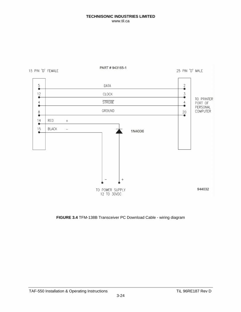
TECHNISONIC INDUSTRIES LIMITED www.til.ca
TAF-550 Installation & Operating Instructions TiL 96RE187 Rev D3-24
FIGURE 3.4 TFM-138B Transceiver PC Download Cable - wiring diagram

Technisonic Industries Limited
240 Traders Blvd., Mississauga, ON Canada L4Z 1W7 Tel: (905) 890-2113 Fax: (905) 890-5338
IMPORTANT WARRANTY
All communication equipment manufactured by Technisonic Industries Limited is warranted to be free of defects in Material or Workmanship under normal use for a period of one year from Date of Purchase by the end user. Warranty will only apply to equipment installed by a factory approved and/or authorized facility in accordance with Technisonic published installation instructions. Equipment falling under the following is not covered by warranty: • equipment that has been repaired or altered in any way as to affect performance, • equipment that has been subject to improper installation, • equipment that has been used for purposes other than intended, • equipment that has been involved in any accident, fire, flood, immersion or subject to
any other abuse. Expressly excluded from this warranty are changes or charges relating to the removal and re-installation of equipment from the aircraft. Technisonic will repair or replace (at Technisonic's discretion) any defective transceiver (or part thereof) found to be faulty during the Warranty Period. Faulty equipment must be returned to Technisonic (or its authorized Warranty Depot) with transportation charges prepaid. Repaired (or replacement) equipment will be returned to the customer with collect freight charges. If the failure of a transceiver occurs within the first 30 days of service, Technisonic will return the repaired or replacement equipment prepaid. Technisonic reserves the right to make changes in design, or additions to, or improvements in its products without obligation to install such additions and improvements in equipment previously manufactured. This Warranty is in lieu of any and all other warranties express or implied, including any warranty of merchantability or fitness, and of all other obligations or liabilities on the part of Technisonic. This Warranty shall not be transferable or assignable to any other persons, firms or corporations.
For warranty registration please complete the on-line Warranty Registration Form found at www.til.ca.