Embed Size (px)
Citation preview

1113/Engg/BE/Pre Pap/2013/CMPN/Soln/MC 1
Vidyalankar B.E. Sem. VII [CMPN]
Mobile Computing Prelim Question Paper Solution
Application of Mobile Computing The following applications describe the need of mobile communications. Vehicles Transmission of news, road conditions, weather, music via Digital Audio Broadcasting (DAB). Current position of the vehicle can be known via the Global Positioning System (GPS). Cars in the same area could build a local ad-hoc network to ensure a minimum safe distance
from other cars. This network could also be used to alert other cars and hospitals in case of anaccident.
Emergencies and Natural Disasters The condition of the patient can be transmitted to the hospital from the ambulance itself. The
hospital can then make the necessary arrangements to speed up the treatment. In case of disasters like earthquakes, cyclones, heavy rains etc. most of the wired networks
and the infrastructure based networks completely fail. On demand, ad-hoc wireless networks are the only way for communication is such cases.
Ad-hoc wireless networks are also useful on the battlefield (in wars) as the existentcommunication network might have already been destroyed (jammed) by the enemy.
Replacement of Fixed (Wired) Networks Remote sensors used for weather forecasts, earthquakes detection etc. can be wireless, this
allows freedom from miles of cabling. Instead of fixed networks, wireless networks can be used for information display and
enforcing security measures in historical monuments, as the cabling required for the fixed network may cause damage to the monument.
Business A travelling salesman can have instant access to the company’s database. Thus, he can easily
provide the latest product info to the customers. Also, the managers can keep track of the performance of the salesman. The laptop can truly be turned in to a mobile office.
Near and Far Terminal Problem Consider three phones placed in the order as shown in figure 1. Both A and B transmit signals at the same power level. By the time A’s signal reaches C, the power level of the signal decreases considerably
(inverse square law) On the other hand, as B is much closer to C, the power level of B’s signal is much higher. Thus, B’s signal would completely drown A’s signal, and C cannot receive A’s transmission. This is called as the near far effect. This effect poses a very severe problem in wireless systems using CDM.\ In a system using CDM, all the signals must arrive at the receiver at about the same power
level. In case a terminal near the receiver transmits at a high power then the receiver cannot detect
any other signals. The situation is even worse if the receiver is a base station coordinating media access. The
base station cannot apply a fair scheme as it cannot hear any other signals.
1. (a)
1. (b)
Vidyala
nkar

Vidyalankar : B.E. MC
1113/Engg/BE/Pre Pap/2013/CMPN/Soln/MC 2
Fig. 1 : Near and Far Terminals To avoid the near-far effect, precise power control is necessary is CDM system, for example,
UMTS adapts power 1500 times/sec.
Network Signaling with Signaling System No. 7 (SS7) SS7 defines a set of telephony signaling protocols by which network elements in PSTN
exchange information over a digital signaling network. Also known as CCSS7 (Common Channel Signaling System 7) Standardized by the International Telecommunication Union (ITU) The SS7 network enables services such as : Basic call setup, management, and tear down. Local Number Portability (LNP) Toll-free and toll wireline services. Enhanced call features such as call forwarding, calling party name/number display and
three-way calling. Efficient and secure worldwide telecommunications. Signaling Points A signaling point uses a routing table to select the appropriate signaling path for each
message.
Fig. 1 : SS7 Architecture
As shown in the figure 1, there are three kinds of signaling points in the SS7: i) SSP (Service Switching Point)
SSP’s are PSTN switches that originate or terminate calls, or route calls to other switches (tandem switches)
SSP’s exchange SS7 messages to set up, manage and release voice circuits. An SSP may also send a query message to a centralized database (an SCP) to determine
how to route a call.
ii) STP (Signal Transfer Point) STP is a packet switch that routes network traffic between signaling points.
An STP routes each incoming message to an outgoing signaling link based on routing information contained in the SS7 message.
1. (c)
Vidyala
nkar
Prelim Question Paper Solution
1113/Engg/BE/Pre Pap/2013/CMPN/Soln/MC 3
Additionally an STP can also act as a “firewall” to screen SS7 messages exchanged with other networks.
iii) SCP (Service Control Point) SCP’s are database servers that respond to requests from SSP’s for call routing information. The signaling points are usually deployed in mated pair configuration in separate physical
information. This ensures network-wide service in the event of an isolated failure. If one of the links fails;
the signaling traffic can be rerouted over another link. Signaling Links SS7 messages are exchanged between network elements over 56 kbps or 64 kbps
bidirectional channels called signaling links. Signaling is out-of-band; meaning that SS7 signaling links are dedicated channels, separate
from voice channels. Out-of-band signaling provides :
Faster call setup times [compared to in-band signaling using Multi-Frequency (MF) signaling tones]
More efficient use of voice circuits. Support for Intelligent Network (IN) services which require signaling to network
elements without voice trunks (e.g. database systems) Improved control over fraudulent network usage.
Signaling Link Types Figure 2 illustrates the different types of signaling links in SS7.
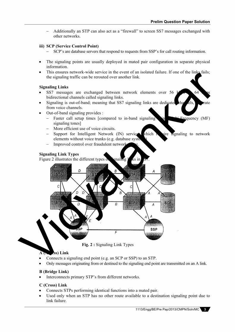
Fig. 2 : Signaling Link Types
A (Access) Link Connects a signaling end point (e.g. an SCP or SSP) to an STP. Only messages originating from or destined to the signaling end point are transmitted on an A link.
B (Bridge Link) Interconnects primary STP’s from different networks.
C (Cross) Link Connects STPs performing identical functions into a mated pair. Used only when an STP has no other route available to a destination signaling point due to
link failure.
Vidyala
nkar

Vidyalankar : B.E. MC
1113/Engg/BE/Pre Pap/2013/CMPN/Soln/MC 4
D (Diagonal) Link It is similar to a B link. Interconnects secondary (e.g. local or regional) STP pair to a primary (e.g. inter-network
gateway) STP pair. E (Extended) Link Connects an SSP to an alternate sTP. Provides an alternate signaling path if an SSP’s home STP cannot be reached via an A link. F (Fully Associated) Link Connects two signaling end points (i.e. SSPs and SCPs) Generally used only in networks that do not have STPs. Bluetooth Protocol Stack
The various layers and protocols of the core specification are as follows, Radio Layer
Bluetooth operates in the 2.4 GHz ISM license free band with a bandwidth limited to 1 MHz per channel. The symbol rate is 1 Msymbol/sec.
It uses G-FSK modulation with a bandwidth-bit period product BT = 0.5. It uses FHSS with a typical hopping rate of 1600 hops/s. It uses Time Division Duplex (TDD) for send/receive separation. Operating range is 10 meters or less. Can be extended up to 100 meters. Data rate is about 730 Kbits/s. As shown in table 1, Bluetooth transceivers are available in three classes depending on
the required power.
Device Class Maximum Power Nominal Power Minimum Power ControlClass 1 100 mW N/A 1 mW Mandatory Class 2 2.5 mW 1 mW 0.25 mW Optional Class 3 1 mW N/A N/A Optional
Baseband Layer It is the part of the Bluetooth system that specifies or implements the medium access and
physical layer procedures between Bluetooth devices. This layer is responsible for the following fuctions, Connection establishment (paging and enquiry) Packet formats
2. (a)
Vidyala
nkar

Prelim Question Paper Solution
1113/Engg/BE/Pre Pap/2013/CMPN/Soln/MC 5
Timing (clock management) Frequency (hopping pattern) selection Basic QoS parameter negotiation Power management
Link Manager Protocol (LMP) The LMP manages the following aspects of the radio link between the devices,
Authentication, pairing, encryption Clock synchronization Capability negotiation Quality of Service negotiation Power control Link supervision State and transmission mode change
Host Controller Interface (HCI) The HCI is a standardized interface between the host controller and the host controller
and the host and also provides a communication protocol between them. It defines the set of functions of a Bluetooth module that are accessible to the host and its
applications. HCI can be seen as a hardware/software boundary. Implementation of HCI is not mandatory and in some fully integrated systems it may not
even be necessary.
Logical Link Control and Adaptation Protocol (L2CAP) It is responsible for the adaptation of the higher layers to the baseband layer. It provides three different types logical channels on top of the baseband layer. Connectionless channels, typically used for broadcast from master to slaves. Connection-oriented channels, these are bi-directional with QoS flow specifications. Signaling channels, used to exchange signaling messages between L2CAP entities.
Service Discovery Protocol (SDP) The SDP allows devices in the Bluetooth environments to locate the available services. SDP is adapted to the highly dynamic environment. SDP defines only the discovery of services and not say anything about their usage. A typical SDP transaction is as follows,
Client sends a request to search for a service of interest. The server responds with the list of available services that match the client’s criteria. The client uses this list to retrieve additional service attributes for the service of interest.
The various layers and protocols of the profile specification are, RFCOMM It is primarily, a cable-replacement protocol that provides a serial line interface to the existing
applications. This allows many legacy applications and protocols to run on Bluetooth. RFCOMM supports multiple serial ports over a single physical channel.
Telephony Control Protocol Specification Binary (TCS-BIN) It describes a binary, packet based, bit-oriented protocol that defines call control signaling for
the establishment of voice and data calls between Bluetooth devices. It also describes mobility and group management functions.
AT Modem Commands These commands are used in cases where an application is supported by a modem service. For example, the headset, fax and dial-up networking profiles use AT commands for
telephony control.
Vidyala
nkar

Vidyalankar : B.E. MC
1113/Engg/BE/Pre Pap/2013/CMPN/Soln/MC 6
Building hierarchies in adhoc networks
Bluetooth Network Encapsulation Protocol (BNEP) The BNEP encapsulates packets from various networking protocols, which are transported
directly over L2CAP. Encapsulation is provided by replacing the networking header, such as an Ethernet header,
with BNEP headers. It allows for the transport of both control and data packets over Bluetooth.
BNEP is used by the Personal Area Networking Profile (PAN) to provide on-demand networking capabilities between Bluetooth devices.
Object Exchange Protocol (OBEX) It provides a session protocol for transactions between two devices. Used for various purposes such as, Generic object exchange Synchronization File transfer The object formats that can be exchanged via OBEX are vCard, vCalender, vMessage and vNote. Audio It is basically not a distinct protocol layer but rather a fundament part of the baseband layer,
i.e.; audio is essentially integrated in to the baseband. Audio applications can directly use the baseband layer after encoding the audio signals.
Hierarchical adhoc routing DSDV & DSR work for a limited numbers of nodes and heavily depend on mobility of nodes. clustering of nodes and using different routing algorithms within clusters enables network scalable and efficient. Here nodes of other clusters only need to know how to reach other cluster. Clusters are combined to form super node which act as cluster heads and represents a router to all / from cluster. Nodes within the cluster and all other cluster heads use these as gateway for the cluster.
The above figure shows the interconnection to internet via a base station of ad hoc network. Cluster head Gateway switch Routing This is a representative of hierarchical routing algorithm based on distance vector routing hierarchy algorithms help to reduce routing tables. It is difficult to maintain the cluster structures in highly mobile environment. Hierarchical state routing is an algorithm based on linkstate principle in which the clusters are recursive and create multiple levels of clusters. Zone routing protocol is a typical hybrid hierarchical routing protocol. A node using ZRP has predefined zone with the node as center which comprises all other nodes within certain hoplimit.
2. (b)
Vidyala
nkar
Prelim Question Paper Solution
1113/Engg/BE/Pre Pap/2013/CMPN/Soln/MC 7
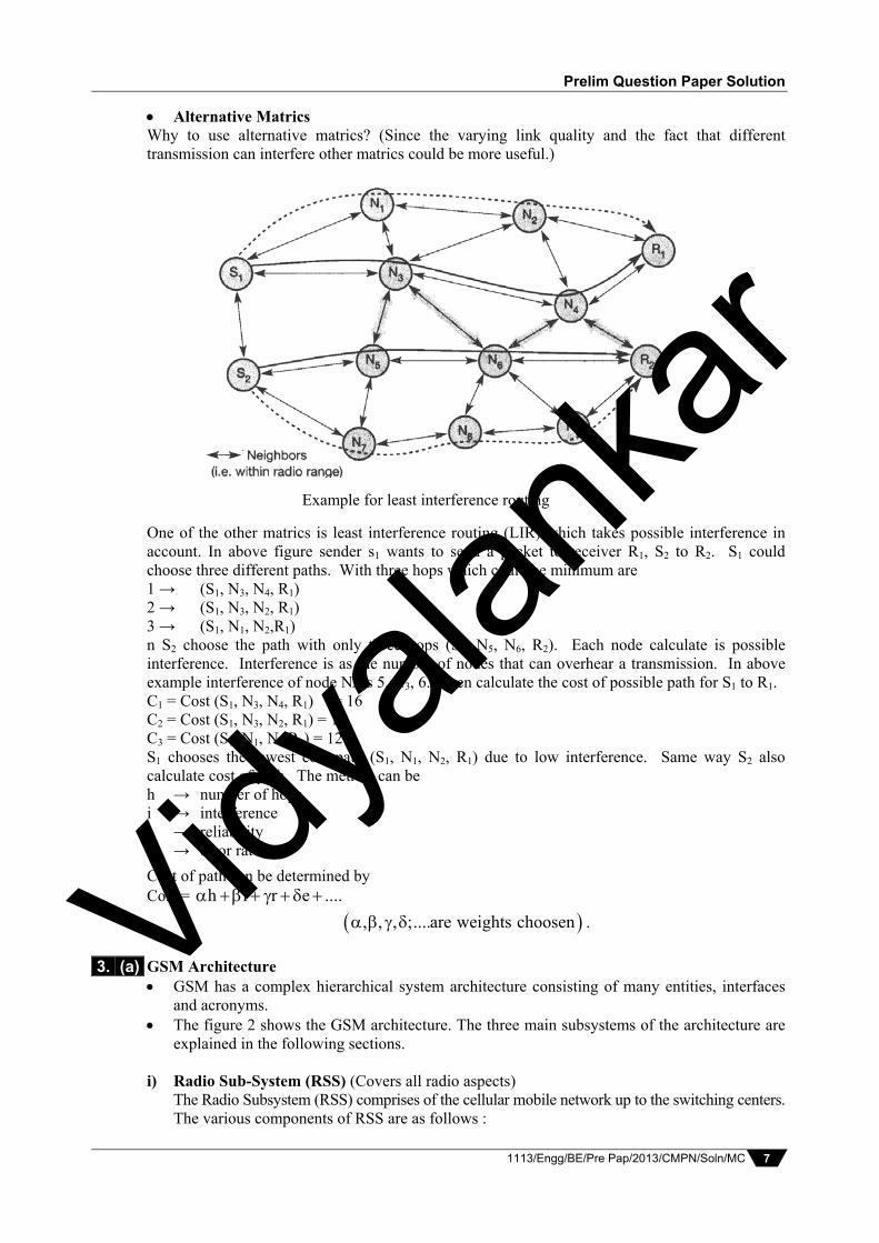
Alternative Matrics Why to use alternative matrics? (Since the varying link quality and the fact that different transmission can interfere other matrics could be more useful.)
One of the other matrics is least interference routing (LIR) which takes possible interference in account. In above figure sender s1 wants to send a packet to receiver R1, S2 to R2. S1 could choose three different paths. With three hops which could be minimum are 1 → (S1, N3, N4, R1) 2 → (S1, N3, N2, R1) 3 → (S1, N1, N2,R1) n S2 choose the path with only three hops (S2, N5, N6, R2). Each node calculate is possible interference. Interference is as the number of nodes that can overhear a transmission. In above example interference of node N4 is 5, N3, 6. Then calculate the cost of possible path for S1 to R1. C1 = Cost (S1, N3, N4, R1) = 16 C2 = Cost (S1, N3, N2, R1) = 15 C3 = Cost (S1, N1, N2,R1) = 12 S1 chooses the lowest cost path (S1, N1, N2, R1) due to low interference. Same way S2 also calculate cost of path. The metrics can be h → number of hops i → interference r → reliability e → error rate.
Cost of path can be determined by Cost = h i r e ....
, , , ;....are weights choosen .
GSM Architecture GSM has a complex hierarchical system architecture consisting of many entities, interfaces
and acronyms. The figure 2 shows the GSM architecture. The three main subsystems of the architecture are
explained in the following sections. i) Radio Sub-System (RSS) (Covers all radio aspects) The Radio Subsystem (RSS) comprises of the cellular mobile network up to the switching centers. The various components of RSS are as follows :
3. (a)
Example for least interference routing
Vidyala
nkar

Vidyalankar : B.E. MC
1113/Engg/BE/Pre Pap/2013/CMPN/Soln/MC 8
Base Station Subsystem (BSS) A GSM network comprises of many BSSs. Each BSS contains several BTSs. Each BSS is controlled by a Base Station Controller (BSC), Thus, BSS = BSC + Sum (BTS) + Interconnection Functions : Maintain necessary connections to MS. Coding / Decoding of voice. Rate Adaption to/from the wireless network. Base Transceiver Station (BTS) A BTS comprises of all the radio equipment such as antennas, digital signal processors,
and amplifiers etc. which are necessary for radio transmission. It typically operates in a region called as cell. A single BTS may form a single cell or
with the help of sectorized antennas, it can form several cells. Functions Transcoding and rate adaptation. Time and frequency synchronizing. Voice through full or half-rate services. Decoding, decrypting and equalizing received signals. Random access detection. Timing advances, Uplink channel measurements. Base Station Controller (BSC) BSC manages the BTSs. The main function of BSC is to multiplex the radio channels on to the fixed network
connections at the A interface i.e. It manages the radio and terrestrial channels. Additional functions include Control of frequency hopping Performing traffic concentration to reduce the number of lines from the MSC. Providing an interface to the Operations and Maintenance Center for the BSS. Reallocation of frequencies among BTSs. Time and frequency synchronization. Power management. Time-delay measurements of received signals from the MS. Mobile Station (MS) The MS comprises of all the hardware/software required by the user to communicate with
the GSM network and access its services. The MS basically consists of user equipment and a SIM. The International Mobile Equipment Identity (IMEI) number is used to uniquely identify
user equipment. (Press *#06# on your mobile phone to find out your IMEI). Device specific mechanisms like theft protection use the IMEI number. The Subscriber Identity Module (SIM), stores all the user specific data that is relevant to GSM. User specific mechanisms like charging and authentications are based on the SIM rather
than the equipment itself. Without the SIM, only emergency calls are possible. The SIM contains a Personal Identity Number (PIN), Pin Unblocking Key (PUK), an
Authentication key and an International Mobile Subscriber Identity (IMSI) number. The MS also stores dynamic information about the user logged onto the GSM network
such as the Cipher key, KC.
Vidyala
nkar

Prelim Question Paper Solution
1113/Engg/BE/Pre Pap/2013/CMPN/Soln/MC 9
Location information about a user is maintained with the help of Temporary Mobile Subscriber Identity (TMSI) and the Location Area Identification (LAI).
The transmit power required for MS ranges from 1 to 2 Watts. The MS may also support various services like IrDA, Bluetooth, Camera, FM, Voice
recorder, Games etc.
Fig. 1 : GSM architecture Interfaces Um is the radio interface connecting the MS and the BTs. Abis connects the BTS to the BSC; it is a standardized, open interface with 16 kbit/s user
channels. The A interface connects the RSS to the Network and Switching Sub-System (NSS) and
is typically based on the circuit switched PCM-30 systems; it is a standardized, open interface with 64 Kbits/s user channels.
The O interface connects the OSS to the RSS and uses the Signaling System 7 (SS7). ii) Network and Switching Subsystem (NSS)
NSS is the main component of GSM architecture. The NSS is responsible for switching, mobility management, and interconnection to other
networks, system control, charging and accounting. The NSS comprises of the following components Mobile Services Switching Center (MSC) MSCs are basically high performance ISDN switches. A single MSC manages several BSCs in a particular area. The primary functions of a MSC are as follows :
Vidyala
nkar

Vidyalankar : B.E. MC
1113/Engg/BE/Pre Pap/2013/CMPN/Soln/MC 10
Paging Coordination of call setup for all MSs in its operating area Dynamic allocation of resources Location registration Handover management Billing Reallocation of frequencies to BTSs Encryption Echo cancellation Signaling exchange Synchronizing the BSS Gateway to SMS Provide supplementary services A Gateway MSC (GMSC) has additional connections to fixed networks like PSTN and
ISDN. Using additional interworking functions (IWF), and MSC can also connect to Public Data
Networks (PDN) such as X.25. The NSS maintains the following databases : Home Location Register (HLR) It is the central master database containing user data, permanent and semi-permanent data
of all subscribers assigned to the HLR (one provider can have several HLRs) It is the most important database in the GSM system. HLR supports charging and accounting. The HLR comprises of the following information. Static information like Mobile Subscriber ISDN number (MSISDN) International Mobile Subscriber Identity (IMSI) Subscriber services such as roaming services, call forwarding etc. Dynamic information like Current Location Area (LA) Mobile Subscriber Roaming Number (MSRN) Current VLR and MSC assigned to a user As soon as a MS leaves a particular LA, the information in the HLR is updated. HLRs have to manage data for several million users; they therefore use highly specialized
databases which can satisfy the strict real time requirements.
Visitor Location Register (VLR) (Dynamic Database) Each MSC has a corresponding VLR. The VLR stores all the important information about the users who are currently in the
location area corresponding to the MSC. This information includes IMSI number, MSISDN, the HLR address etc. When a new user enters the LA corresponding to the MSC, the associated VLR copis all
the relevant information about the user from the HLR. The VLR avoids frequent HLR access/updates, as all the user information required (by
MSC or BSC) is available in the VLR.
iii) Operational Subsystem (OSS) The OSS enables centralized operation, management, and maintenance of all GSM subsystems. The OSS accesses other entities via SS7 signaling.
The components of OSS are as follows : Authentication Center (AuC) It is responsible for protection of user identity and data over the air interface.
Vidyala
nkar

Prelim Question Paper Solution
1113/Engg/BE/Pre Pap/2013/CMPN/Soln/MC 11
It generates user specific authentication parameters on request of a VLR. It contains the algorithms for authentication (A3) as well as the keys for encryption (KC). The AuC may be situated in a special protected part of the HLR. Operation and Maintenance Center (OMC) The OMC is responsible for various functions like : Traffic monitoring Subscriber and Security management Status reports of network entities Accounting and billing OMC’s use the concept of Telecommunication Management Network as specified by
the ITUT. Equipment Identity Register (EIR) It contains the IMEI of all the user equipments. With the help of IMEI, stolen or malfunctioning mobile stations can be locked and
sometimes even localized. Thus the EIR contains the following lists, A blacklist containing IMEI of stolen/locked devices. A white list containing IMEI of valid devices. A grey list containing IMEI of malfunctioning devices. A major problem is that the blacklists of different service providers may not be synchronized.
Orbits
Fig. 1: Types of Orbits
i) Geostationary / Geosynchronous Earth orbit (GEO) It’s the outermost orbit, GEO satellites are at a distance of about 36,000 km (35,768)
from earth. These satellites have a period of 24 Hrs, i.e. they have a period equal to that of earth, and
hence the satellites appear to be fixed at a point in the sky. Satellites used for TV and radio broadcasting and for weather forecast all in to this
category. Advantages Three GEO satellites are enough for a complete coverage of almost any spot on earth. Due to the synchronous nature of the satellite, senders and receivers can have fixed
antenna positions, no adjusting is required.
3. (b)
Vidyala
nkar

Vidyalankar : B.E. MC
1113/Engg/BE/Pre Pap/2013/CMPN/Soln/MC 12
GEO satellites have a rather higher lifetime expectancy of about 15 years. Do not exhibit any Doppler shift effect as the relative movement with respect to earth is zero. A GEO system typically does not require handovers due to large footprint size.
Disadvantages There is a latency of 0.25 Sec one-way. This is a BIG problem for voice and data
communication. Most of the retransmission schemes known from fixed networks fail. Since it is an equatorial orbit, as the latitude or longitude difference between the satellite
and earth station increases, the angle of elevation decreases. Low elevation angles can be a problem for mobile communications.
The transmit power needed is about 10W this can pose a severe problem for battery powered handheld devices.
Due to the large footprint of a satellite, either frequencies cannot be reused or the satellite needs special antennas focusing on a smaller footprint.
Launching a GEO satellite in to orbit is very expensive.
ii) Medium Earth Orbit (MEO) MEO operates at a distance of about 5000-12000 km from earth. It is also known as Intermediate Circular Orbit (ICO) It can be positioned in between GEOs and LEOs, both in terms of its orbit and its
advantages and disadvantages. MEO satellites have a period of about 6 Hrs. Satellites used for land and sea navigation fall in to this category. Example, Intermediate Circular Orbit (ICO) satellite system.
Advantages At an orbit of about 10,000 km, 12 satellites are enough for global coverage. The system design becomes simpler because of the lower speed of the satellite. Larger size of footprint (as compared to LEO), hence fewer handovers required. Disadvantages
Due to large distance from earth, latency increases to about 70-80 ms. Higher transmission power required. Special antennas required for focusing on a smaller footprint.
iii) Lower Earth Orbit (LEO) This orbit is the closet to the earth, at a distance of about 500-1200 km from earth. LEO satellites have a much shorter period of about 95-120 minutes. Visibility of each satellite from earth is about 10 minutes. Examples, Iridium (66) and Global Start (48).
Advantages Ensure high elevation for almost every spot on earth (even in Polar Regions) and provide
a high quality connection link between the satellite and the sender/receiver. Due to smaller footprint size, frequency reuse is possible. Have a latency of about 5-10 ms, which is comparable to terrestrial long distance
communication. Transmission rates of about 2.4 Mbits/s can be achieved. Transmit power required is about 1W. Therefore, mobile terminals with Omni-directional
antennas can also be used.
Disadvantages A large number of satellites are needed for global coverage. Frequent handovers may be required due to smaller footprint size.
Vidyala
nkar

Prelim Question Paper Solution
1113/Engg/BE/Pre Pap/2013/CMPN/Soln/MC 13
The large number of satellites moving at high speed makes the overall satellite system very complex.
Due to atmospheric drag and the radiation from Van Allen belts, the satellites have a short lifetime expectancy of about 5-8 years. New satellites need to be launched frequently.
WATM Reference Model The generic WATM reference model is shown in the figure 1.
Fig. 1 : WATM Generic Reference Model – The Mobile ATM (MATM) terminal uses the WATM terminal adapter to gain wireless
access to the ATM network via the RAS. – The RAS is connected to the mobility aware ATM switches such as EMAS-E/N, which in
turn are connected to the standard ATM switches that can provide access to a fixed end system.
– The WATM reference model with the different access scenarios is shown in figure 2.
Fig. 2 : WATM Reference Model with Several Access Scenarios The various components involved are T (Terminal) It is the standard ATM terminal that offers the ATM services defined for fixed ATM
networks. MT (Mobile Terminal)
A mobile terminal is a standard ATM terminal that can move between different access points within a certain domain.
MT includes mechanisms for reconnecting after moving to a different access point. WT (Wireless Terminal) It is fixed terminal that can be accessed via a wireless link. WT do not change their access points. WMT (Wireless Mobile Terminal) It is a combination of a WT and MT.
4. (a)
Vidyala
nkar

Vidyalankar : B.E. MC
1113/Engg/BE/Pre Pap/2013/CMPN/Soln/MC 14
It can change its access point and can be accessed via a wireless link. EMAS-E/N (End-User Mobility Supporting ATM Switch, E-Edge, N-Network) These switches are responsible for supporting end use mobility. NMAS (Network Mobility Supporting ATM Switch) Along with the terminals, the entire network can move from one point to another. NMAS includes the additional mechanisms required for supporting this mobility of the
network. RAS (Radio Access System) The terminals and MS can use the RAS to access the ATM network via a radio link. MS (Mobile ATM Switch) ATM switches can also mobile. MS can access other parts of a network via a radio link. ACT (Ad-hoc controller Terminal) It is a special terminal responsible for the configuration of ad-hoc networks. It allows wireless access without using a RAS. The six access scenarios shown in the figure 2 are,
i) Wireless Ad-hoc ATM Network In this scenario, the WMTs can communicate with each other without relying on any
infrastructure. The ACT is responsible for access control. RAS allows the WMTs to communicate with a fixed network.
ii) Wireless Mobile ATM Terminals WMT’s can access the fixed networks via RAS. In order to communicate the WMTs to communicate with a fixed network.
iii) Mobile ATM Terminals This scenario supports device portability and supports simple network
reconfiguration. The MTs can automatically reconfigure if the access point is changed. In order to communicate the MTs need the support of fixed network entities such as
EMAS-E. iv) Mobile ATM Switches This is perhaps the most complex scenario. In this scenario the mobile switches can access other networks via a wireless link. Entities such as NMAS are now required to support the mobility of the switches. v) Fixed ATM Terminals
The terminals and switches in this configuration do not include any capabilities for mobility or wireless access i..e the terminals and switches are typically fixed.
It is a reference configuration for applications working on top of an ATM Network. vi) Fixed Wireless ATM Terminals The WTs can access the network via a wireless link (no wired infrastructure required) RAS allows the WTs to communicate with a fixed network. This scenario does not require any changes or enhancements in the fixed network.
Application of Satellites Astronomy An astronomy satellite is actually a really big telescope floating in space. Astronomy satellites have various uses like, They can be used to make star maps. They can be used to study mysterious phenomena such as black holes and quasars. They can be used to take pictures of the planets in the solar system. They can be used to make maps of different planetary surfaces. The Hubble Space Telescope is an example of an astronomy satellite.
4. (b) Vidyala
nkar

Prelim Question Paper Solution
1113/Engg/BE/Pre Pap/2013/CMPN/Soln/MC 15
Agriculture Many countries use satellite technology to improve agriculture. Satellites are used to
determine productive from non-productive yields. Satellite-based navigation, such as the Global Positioning System (GPS), typically, a military
invention, also assists in the process of reviewing agricultural production. Farmers can keep track of what they plant, fertilize, and spray. A farmer can now account for
different kinds of soil, varying in acidity, organic content, and nitrogen levels. Weather Forecasting Several satellites deliver pictures of earth using, visible light or infrared. Radiation measurements from the earth’s surface and atmosphere give information on
amounts of heat and energy being released from the earth and the earth’s atmosphere. Used to forecast rains, cyclones, hurricanes etc. For example, Meteosat is a geostationary weather satellite launched by the European Space
Agency (ESA) Other general applications of satellites include Radio and T.V. broadcasts Espionage to monitor the enemy’s movements. Navigation i.e. the use of Global Positioning System (GPS) for precise worldwide localization Broadband satellites – to provide Internet access remote areas. Global Mobile Communication In the context of mobile communications, the main usage of satellites to explained below. Cellular systems like GSM, AMPS usually do not cover all the parts of a country. In sparsely populated areas, installing a base station just for coverage can be very expensive. The solution to this is to use satellite communication after moving out of the coverage area of
a regular cellular system. Thus, world wide mobile connectivity is available to the user. Today’s satellites are more like flying routers. The satellites can convert the analog signal into a bit stream, use digital signal processing
techniques to regenerate the signal then retransmit the signal. This can drastically improve the quality of the signal received on earth.
Fig. 1 : A Typical Satellite System
The figure 1 shows the classical scenario for satellite systems supporting global communication.
Each satellite covers a certain area on earth; this area is called as its footpint.
Vidyala
nkar
Vidyalankar : B.E. MC
1113/Engg/BE/Pre Pap/2013/CMPN/Soln/MC 16
Within the footprint, communication with the satellite is possible via a Mobile User Link (MUL) and for the land base station controlling the satellite and acting as a gateway to other networks or footprints via the Gateway Link (GWL).
Two satellites can either communicate via the land gateway or they can use Inter-Satellite Links (ISL).
Using ISL reduces the latency for data packets and voice data because the extra links from satellite to gateway are not needed.
A real challenge for the global mobile phone system is to provide a smooth, seamless handover between a cellular network (such as GSM) and a satellite system.
General problems of Mobile IP regarding the Quality of Service Security Issues Firewalls, in particular, cause difficulty for mobile IP because they block all classes of
incoming packets that do not meet specified criteria. Enterprise firewalls are typically configured to block packets from entering via the Internet
that appear to emanate from internal computers. Although this permits management of internal Internet nodes without great attention to
security, it presents difficulties for mobile nodes wishing to communicate with other nodes within their home enterprise networks.
Such communications, originating from the mobile node, carry the MNs home address (in a foreign network), and would thus be blocked by the firewall.
In many cases, authentication with the FA is problematic as the FA typically belongs to another organization or network.
There is no standardized protocol for key management and key distribution, different vendors use different protocols which further makes the coordination difficult.
There are several patent and export restrictions. For example an organization could hold a patent on its encryption technology and thus prevent others from using it.
QoS Issues The QoS solution for mobile IP should satisfy obvious requirements such as scalability,
conservation of wireless bandwidth, low processing overhead, authorization and accounting, and robustness against failure of any mobile IP specific QoS components in the network.
When handover occurs in mobile IP environment, some applications such as Web browser and file transfer using TCP as the transport protocol will face disconnection or a degradation of the performance.
A problem arising from the tunnel-based communication is that tunnel based communication is that different data flows addressed to the same terminal (same IP address) are treated in the same manner.
Thus, tunneling makes it hard to give a flow of packets a special treatment needed for the required QoS.
Personal Communication Services (PCS) Architecture PCS refers to a set of services that provide a mobile user with voice, data and multimedia
anywhere, anytime and in any given format. Most of PCS systems are connected to the fixed networks such as the Public Switched
Telephone Network (PSTN). However, with the widespread use of the Internet in the current market these systems are
increasingly adapting and interfacing with the Internet and are driven by the Internet standards.
The basic architecture of any general PCS system shown in the figure 1, consists of 2 parts. i) Radio Network
Individual Mobile Phones (stations) through which the user is connected to the system.
5. (a)
5. (b) Vidyala
nkar

Prelim Question Paper Solution
1113/Engg/BE/Pre Pap/2013/CMPN/Soln/MC 17
The Base Transceiver Stations (BTS) which typically controls one cell. The number of cells may vary depending on the PCS system.
The Base Station Controller (BSC) controls several BTSs and is responsible for interaction with the MSC.
The BSCs usually reach the wireline transport network (core or backbone network) via land links or dedicated microwave links.
ii) Wireline Transport Network Mobile Switching Center (MSC) which is connected to the Mobility database that keeps
track of the mobile users and their location. The MSC acts as the interface between the Radio Network and the PSTN.
The various PCS systems are classified as follows : High Tier Cellular Systems Advanced Mobile Phone Service (AMPS) EIA/TIA IS-136 Digital Cellular System (DAMPS) Global System for Mobile Communication (GSM) EIA/TIA IS-95 Digital Cellular System (CDMAOne).
Low Tier Cellular Systems and Cordless Telephony Cordless Telephone, Second Generation (CT2) Digital European Cordless Telephone (DECT) Personal Handy Phone System (PHS) Personal Access Communication System (PACS).
Fig. 1 : General PCS Architecture
3G Wireless Wideband Systems Wideband Code Division Multiple Access (W-CDMA)/UMTS. IS-2000/CDMA2000; an evolution of CDMAOne/IS-95 to 3rd generation services. Unlicenced Systems Systems operating in the Industry, Scientific, Medical (ISM) band. Wireless Local Area Networks (W-LAN) A brief comparison of the PCS categories is shown in the table 1.
System High Tier Cellular Low Tier Cellular Cordless Cell size Large (0.25-38 km) Medium (10-100 m) Small (10-20 m)
User speed High ( 250 km/h) Medium ( 100 km/h) Low ( 50 km/h) Handset complexity High Low Low
Handset power consumption
High (100-800 mW) Low (5-20 mW) Low (5-10 mW)
Public switched telephony network
Vidyala
nkar

Vidyalankar : B.E. MC
1113/Engg/BE/Pre Pap/2013/CMPN/Soln/MC 18
Speech coding rate Low (8-13 kbps) High (32 kbps) High (32 kbps) Delay or latency High Medium Low (Often flat rate)
Examples GSM, D-AMPS, PDC, cdmaOne, UMTS,
CT2, DECT, PHS, PACS
Agent Discovery Agent discovery allows the MN to, Determine whether it is at home or not. Detect whether it has moved. Obtain a COA when away from home. Agent discovery consists of 2 messages, agent advertisement and agent solicitation i) Advertisement
The functions performed by an agent advertisement are the as follows, Allows the detection of HAs and FAs. Lists one (or more available) COA Informs the MN about special features provided by FA, say, for example a list of
alternative encapsulation techniques supported. Permits MNs to determine the network number and congestion status of their link to
the Internet. Lets the MN know, whether it is in its home network or in a foreign network by
identifying whether the agent is a HA, a FA, or both. The agent advertisement packet along with the extension for mobility is as shown in figure 1.
Fig. 1 : Agent Advertisement Packet The various fields in the ICMP part of the packet are
Type : It is set to 9. Code : It is set to 0 if the agent also routes traffic from non-mobile nodes. It is set to
16 if the agent only routes mobile traffic. Num Addrs : It indicates the number of addresses advertised with this packet. The
actual addresses follow as shown in the figure. Lifetime : It denotes the duration for which the packet is valid. Preference Level : A preference level is specified for each address. It helps the MN
to select a specific router.
6. (a)
Vidyala
nkar
Prelim Question Paper Solution
1113/Engg/BE/Pre Pap/2013/CMPN/Soln/MC 19
The various fields in the Mobility Extension part of the packet are , Type : It is set to 16. Length : It indicates the number of COAs provided with the message. It is equal to
6 + 4* (Number of Addresses) Sequence Number : It specifies the total number of advertisements sent since
initialization. Registration Lifetime : It specifies the maximum lifetime a node can request during
registration. The bits used to specify the characteristics of the agent are as follows,
R Bit : If set, it indicates that a registration with this agent is required even if the MN is using a co-located COA.
B Bit : If set, it indicates that the agent is too busy to accept new registrations. H Bit : If set, it indicates that the agent is offering services as a HA. F Bit : If set, it indicates that the agent is offering services as a FA. M Bit : If set, it indicates that Minimal Encapsulation is used for tunneling. G Bit : If set, it indicates that Generic Routing Encapsulation is used for tunneling. T Bit : Indicates whether reverse tunneling is supported by the FA.
ii) Agent Solicitation
If a mobile node does not receive an agent advertisement within a specified duration, it can send an Agent Solicitation to request the sending of an advertisement.
Any agent that receives the solicitation message then transmits a single agent advertisement in response.
Typically, a MN sends three solicitation messages in one second. If it does not receive a reply soon it should exponentially reduce the sending rate to avoid flooding of the network.
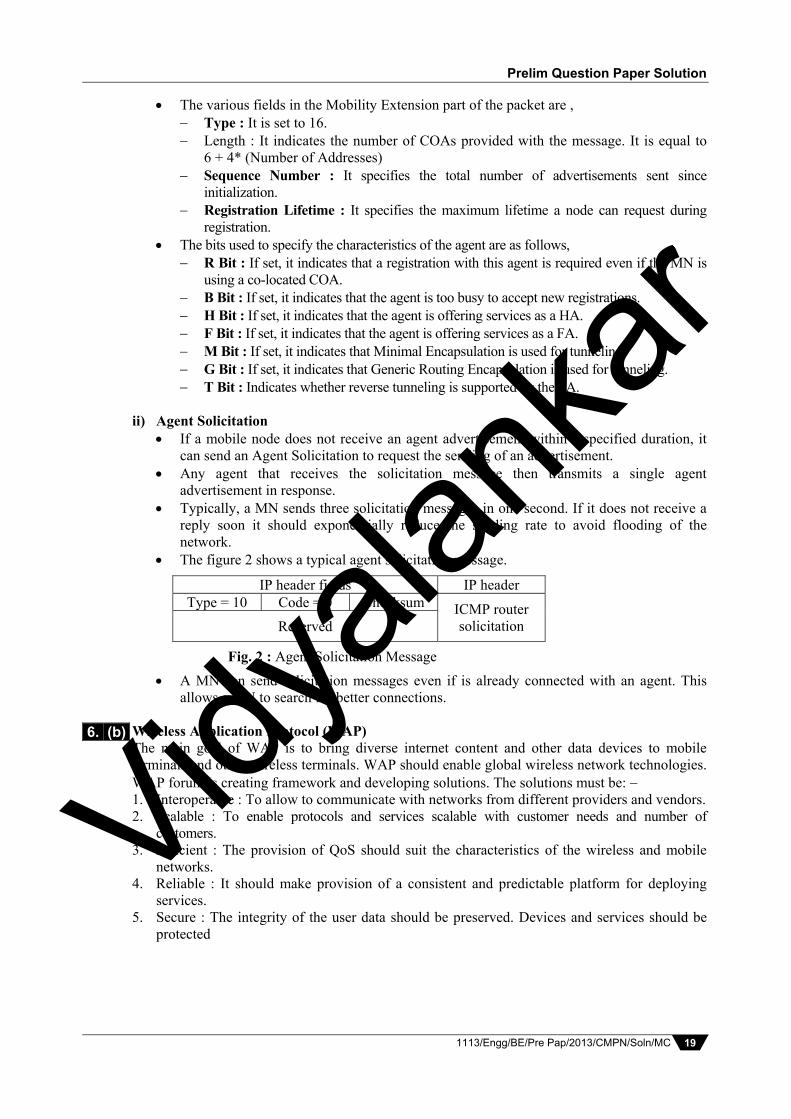
The figure 2 shows a typical agent solicitation message.
IP header fields IP header Type = 10 Code = 0 Checksum ICMP router
solicitation Reserved
Fig. 2 : Agent Solicitation Message
A MN can send solicitation messages even if is already connected with an agent. This allows a MN to search for better connections.
Wireless Application Protocol (WAP) The main goal of WAP is to bring diverse internet content and other data devices to mobile terminals and other wireless terminals. WAP should enable global wireless network technologies. WAP forum is creating framework and developing solutions. The solutions must be: 1. Interoperable : To allow to communicate with networks from different providers and vendors. 2. Scalable : To enable protocols and services scalable with customer needs and number of
customers. 3. Efficient : The provision of QoS should suit the characteristics of the wireless and mobile
networks. 4. Reliable : It should make provision of a consistent and predictable platform for deploying
services. 5. Secure : The integrity of the user data should be preserved. Devices and services should be
protected
6. (b)
Vidyala
nkar

Vidyalankar : B.E. MC
1113/Engg/BE/Pre Pap/2013/CMPN/Soln/MC 20
Architecture
The above figure shows model of component and interface of the WAP 1.X architecture. Let’s study the above figure in ascending order. The transport layer offers a bearer independent, consistent datagramoriented service to the higher layers of the WAP architecture. The transport layer service point (TSAP) is common interface to be used by higher layers independent of the underlying network.
The next higher layer, the security layer with its wireless transport layer security protocols (WTLS) offers its services at security SAP (SECSAP). This WTLS is based on the transport layer security.
WAP transaction layer with wireless transaction protocol (WTP) offers a lightweight transaction service at the transaction SAP (TRSAP), provides reliable or unreliable request and asynchronous transactions.
Session layer is tightly coupled to layer below it. Session layer with wireless session protocol (WSP) offers two services at the sessionSAP (SSAP). There are two kinds, one connectionoriented and connectionless when it is used directly on top of WDP.
Application layer with the wireless application environment (WAE) offers a framework for the integration of different WWW and mobile telephony applications. It provides many protocols and services with special services access points.
It is not necessary for application user to use the whole protocol architecture. Shown in the above figure. If an application does not require security but needs the reliable transport area it can directly use a service of transaction layer.
HIPERLAN (High Performance Radio LAN 1) It is a wireless LAN standard defined by the ETSI. HIPERLAN1 features i) Data transmission Range 50 m Point-to-point, point-to-multipoint, connectionless. 23.5 Mbits/s, 1 W power, maximum packet size 2383 bytes. 5 channels in 5 GHz
7. (a)
Application layer (WAE)
ASAP
Session layer (WSP)
SSAP
Transaction layer (WTP)
TRSAP
Security layer (WTLS)
SECSAP
Transport layer (WDP)
TSAP
HTML, Java
HTTP
SSL / TLS
TCP / IP, UDP / IP, media
Internet WAP
WCMP
Additional services &applications
Components and interface of WAP 1.X architecture
Vidyala
nkar

Prelim Question Paper Solution
1113/Engg/BE/Pre Pap/2013/CMPN/Soln/MC 21
ii) Topology Infrastructure or ad-hoc networks Transmission range can be larger then coverage of a single node. iii) Further Mechanisms Power saving, encryption, checksums etc. iv) Services Synchronous and time-bounded services with hierarchical priorities. HIPERLAN does not conflict with microwave and other using the 2.4 GHz band. HIPERLAN Protocol Stack The HIPERLAN protocol stack is as shown in figure 1. The layers are explained as follows, Fig. 1 : HIPERLAN Protocol Stack Physical Layer The physical layer uses FSK and GMSK modulations. The functions of the physical layer are, Modulation, demodulation, bit and frame synchronization Implement forward error correction meachanisms Measurement of signal strength Channel sensing HIPERLAN Channels HIPERLAN provides 3 mandatory and 2 optional channel Mandatory Channels include Channel 0 at 5.17 GHz, Channel 1 at 5.19 GHZ and
Channel 2 at 5.22 GHz Optional Channels include Channel 3 at 5.24 GHz and Channel 4 at 5.27 GHz Channel Access and Control Layer (CAC) The functions of the CAC layer include Deal with the access requests to the channels. Assure that terminal does not access forbidden channels Provide hierarchical independence with Elimination-Yield Non-Preemptive Multiple
Access Mechanism (EY-NPMA) To provide the requested QoS, the layer offers five priority levels for QoS support. EY-NPMA enables the network to function with few collisions even though there would be a
large number of users. Multimedia applications work in HIPERLAN because of EY-NPMA priority mechanism. The mapping of QoS onto a priority level is done with the help of the packet lifetime. The
mapping process works as follows, An application can set the packet lifetime to a standard start value 500 ms up to a
maximum of 16000 ms. If a terminal cannot send the packet due to its current priority, waiting time is
permanently subtracted from lifetime. Based on the packet lifetime, the waiting time in a sender and number of hops to the
receiver, the packet is assigned to one out of five priorities. The priority of waiting packets, therefore, rises automatically.
Medium access control layer
Channel access control layer
Physical layer
Vidyala
nkar

Vidyalankar : B.E. MC
1113/Engg/BE/Pre Pap/2013/CMPN/Soln/MC 22
MAC Layer The MAC layer provides the following facilities, i) Packet Forwarding
MAC layer supports directed (point-to-point) forwarding and broadcast forwarding. It also provides QoS support while forwarding.
ii) Encryption Mechanisms These mechanisms are integrated in the MAC layer. However, key management is the
responsibility of the higher layer. iii) Power Conservation Mechanism
These mechanisms allow the mobile terminals to be switched off when not needed i.e., when the terminals do not have data to send they can go into a sleep mode.
Mobile terminals can then wake up periodically according to some pre-determined pattern to receive data.
Additionally, some nodes in the networks must be able to buffer data for sleeping terminals.
UMTS
UMTS stands for Universal Mobile Telecommunication System. It is the European proposal for IMT-2000 and is standardized by the ETSI.
The UMTS initially proposed by the ETSI represents an evolution from the second generation GSM system to a third generation system.
The UMTS forum was then set up by a number of telecom operators, manufacturers, national governments, and other organization.
Its aim is to define a common strategy and policy for the development and implementation of UMTS and combining personal communications with multimedia services and applications built on existing fixed and mobile infrastructure.
UMTS Architecture A very simplified UMTS reference architecture is shown in figure 1. The components of the UMTS architecture are explained as follows :
Fig. 1 : UMTS Reference Architecture
Core Network (CN) It communicate with the UTRAN via the Iu interface. This interface is similar to the A
interface (between the BSC and MSC) used in GSM. It is responsible for the following functions : Inter-system handover. Gateways to other network like IADN or PSTN Location management
Universal Terrestiral Radio Access Network (UTRAN) It handles cell level mobility and comprises of many Radio Network Subsystems (RNS). It is connected to the User Equipment via the Radio interface Uu. This interface is
comparable to the Um interface (between the MS and BTS) used in GSM. The function of RNS include Admission control Congestion control System information broadcasting Radio channel encryption and decryption Radio network configuration
7. (b)
Vidyala
nkar

Prelim Question Paper Solution
1113/Engg/BE/Pre Pap/2013/CMPN/Soln/MC 23
Channel quality measurements Radio carrier control Channel quality measurements Radio carrier control Data transmission over the radio interface Channel coding Access control Handover control Radio resource management
User Equipment (UE) This consist of the equipment that the subscriber uses to connect to the UMTS system. The user equipment also contains SIM whose functions are similar to those in GSM.
The simplified architecture of figure 1 is further divided into a number of domains. Figure 2 shows the various domains.
User Equipment Domain It is assigned to a single user and is responsible for all the functions that are needed to
access the UMTS services. It is further divided into,
Fig. 2 : UMTS Domains and Interfaces USIM Domain
It consists of the Subscriber Identity Module (SIM) that performs authentication of the user and various other functions like encryption and decryption.
The USIM also stores all the user related data necessary for UMTS. The USIM typically, belongs to a service provider.
Mobile Equipment Domain The end device itself is in this domain. The mobile equipment contains the USIM.
Infrastructure Domain This domain is shared among all the users. It offers UMTS services to all the
authenticated users. It consist of,
Access Network Domain It contains all the Radio Access Networks (RANs)
Core Network It contains the access network independent functions. This domain can be separated in to three domains, each of which performs a specific task.
Vidyala
nkar
Vidyalankar : B.E. MC
1113/Engg/BE/Pre Pap/2013/CMPN/Soln/MC 24
Serving Network Domain It comprises of all the functions that are current used by the user to access the UMTs
services. Home Network Domain It comprises of all the function related to the home network of the user. Also responsible for location management. Transit Network Domain This is an optional domain. It is necessary only when the user cannot directly reach its home network. Wireless Mark-up Language (WML) WML is a markup language based on XML and is used to specify the content and user
interface for narrowband devices such as cellular phones and pagers and PDAs. WML was designed by taking in to account the following constrains on wireless handheld devices, Small display and limited user input facilities. Narrowband network connection (low bandwidth and high latency) Limited memory and computational resources WML includes four major functional areas which are as follows, i) Text Presentation and Layout
WML includes text and image support, including a variety of formatting and layout commands.
Examples of such tags include bold, italic etc. However, the exact presentation of the data is up to the user agent running on the user
device. ii) Deck/Card Organizational Metaphor (Similar to HDML)
All information in WML is organized into a collection of cards and decks. Logically, a user can navigate through a series of WML cards, review the contents of
each, enter requested information, make desired choices and move on to another card. Cards are grouped together into decks. A WML deck is similar to an HTML page.
iii) Inter-card Navigation and Linking WML provides mechanisms for explicitly managing the navigation between cards and decks. WML supports anchored links, similar to those found in HTML. WML also includes provisions for event handling in the device. These provisions may be
used for navigation or for the execution of scripts. iv) String Parameterization and State Management
All WML decks can be parameterized using a state model. Variables can be used in the place of strings and are substituted at run-time. This
parameterization allows for a more efficient use of network resources. Wireless Telephony Application (WTA) A collection of telephony specific extensions for call and feature control mechanism that provide authors (and ultimately end-users) advanced Mobile Network Service. The WTA framework integrates advanced telephony services using a consistent user interface (e.g. the WML browser) and allows network operators to increase accessibility for various special services in their network. A network operator can reach more end-devices using WTA because this is integrated in the wireless application environment (WAE) which handles device-specific characteristics and environments. The main idea behind the wireless application environment (WAE) is to create a general-purpose application environment based mainly on existing technologies and philosophies of the world wide web. The Wireless Telephony Application Framework has four main goals : Enable Network Operators to provide advanced telephony services that are well integrated and have consistent user interfaces. Enable Network Operators to create customized content to increase
7. (c)
7. (d) Vidyala
nkar

Prelim Question Paper Solution
1113/Engg/BE/Pre Pap/2013/CMPN/Soln/MC 25
demands and accessibility for various services in their Networks. Enable Network Operator to reach a wider range of devices by leveraging generic WAE features that allows the operator to create content independent of device specific characteristics and environments. Enable third party developer to create network-independent content that access basic features (i.e. non-privileged). Requirements for WT device and network independent, international support manufacturers can determine look-and-feel, user interface considerations of slow links, limited memory, low computing power, small display, simple user interface (compared to desktop computers) WTA logical architecture The elements of the logical WTA network, presented in the following figure are : i) Content and Content Generators ii) Firewalls (optional) iii) Mobile Switching Framework
The WTA user agent is connected to the mobile network using dedicated signaling connections. The WTA Server (an origin server) communicates with the client using the WAP protocol stack. The WTA server may be connected to the mobile network and is responsible for deploying content to its clients. Origin servers within the trusted domain may be connected via the WAP gateway. A firewall is used to connect third-party origin servers outside the trusted domain. In the case of call handling for example, the mobile network sets up the call to the client, the server delivers the event-handling content, and the user agent invokes the event-handler content and manages the presentation of the call handling service to the user. The WTA user agent is a content interpreter that extends a typical WML user agent.
It supports extended libraries and executes WML decks and WML Script similar to a WML user agent. However, unlike a typical WML user agent, the WTA user agent has a very rigid and real-time context management component. For example, the user agent drops outdated (or stale) events, does not place intermediate results on the history stack, and typically terminates after the event is handled. If the user wants to listen to the stored messages, he or she can request a list of the messages. This is done with the help of the URL.
Fig. 1 : WTA logical architecture
A WSP get requests the content the URL points to. The gateway translates this WSP get into an HTTP get and the server responds with the prepared list of callers. After displaying the content, the user can select a voice message from the list. Each voice message in this example has an associate URL, which can request a certain WML card from the server. The purpose of this card
Vidyala
nkar

Vidyalankar : B.E. MC
1113/Engg/BE/Pre Pap/2013/CMPN/Soln/MC 26
is to prepare the client for an incoming call. As soon as the client receives the card, it waits for the incoming call. The call is then automatically accepted. The WTA server also signals the voice box system to set up a (traditional) voice connection to play the selected voice messages. Setting up the call and accepting the call are not controlled by WAP.
WTA origin servers The WTA Origin Server is assumed to be under the control of the Network Operator and is therefore to be regarded as a “Trusted Content Server”. The Operator’s server is assumed to control, in varying degrees, the Mobile Network Switch. The success of the WTA content (e.g. handling Call Control) is, to some extend, dependent on the operator’s ability to access and control the features and characteristics of the Mobile Network. The operator has information about latency, capacity and reliability for the different bearers in the Mobile Network. Since the operator is able to provide the WTA services without needing to rely on the Internet, the operator can have more control over the behavior of the services than a third party service provider can, and can better optimize their services to achieve good real-time characteristics. Third party origin severs Content from third party providers does not handle any extensive set of WTA functions. Developing advanced WTA applications requires, in most cases, in-depth knowledge of the mobile network. Due to the limitations imposed by the operator as to which third party is granted access to the mobile network resources and WTA services, third party content providers are limited to handling WAE content using the subscriber’s standard WML user agent. Mobile network The network operator controls the mobile network. The mobile network handles switching and call set-up to the mobile subscribers (or terminals). The mobile network connects with the client using in-band or out-of-band signaling connections. The mobile network-to-client signaling is exposed to the content running in a user agent using WTA network events. Even though the mobile network-to-client messaging uses network-level system-specific signaling at the content level, signaling is converted to more generic and abstract WTA network events. Wireless broadband (WiMax) WiMAX is a short name for Worldwide Interoperability of Microwave Access. WiMAX is described in IEEE 802.16 Wireless Metropolitan Area Network (MAN) standard. It is expected that WiMAX compliant systems will provide fixed wireless alternative to conventional DSL and Cable Internet. Typically, a WiMAX system consists of two parts : a) WiMAX base station Base station consists of indoor electronics and a WiMAX tower. Typically, a base station can
cover up to 10 km radius (Theoretically, a base station can cover up to 50 kilo meter radius or 30 miles, however practical considerations limit it to about 10 km or 6 miles). Any wireless node within the coverage area would be able to access the Internet.
b) WiMAX receiver The receiver and antenna could be a stand-alone box or a PCMCIA card that sits in your
laptop or computer. Access to WiMAX base station is similar to accessing a Wireless Access Point in a WiFi network, but the coverage is more.
Several base stations can be connected with one another by use of high-speed backhaul microwave links. This would allow for roaming by a WiMAX subscriber from one base station to another base station area, similar to roaming enabled by Cellular phone companies. Wireless MAN IEEE 802.16 (WiMAX) Specifications.
Range 30-mile (50-km) radius from base stationSpeed Up to 70 megabits per second Non-Line-of-sight (NLoS) between user and base station Frequency bands 2 to 11 GHz and 10 to 66 GHz (licensed and unlicensed bands) Defines both the MAC and PHY layers and allows multiple PHY layer specifications.
7. (e)
Vidyala
nkar

Prelim Question Paper Solution
1113/Engg/BE/Pre Pap/2013/CMPN/Soln/MC 27
Application of WiMAX are given below : i) Residential and SOHO high speed internet Access The main contenders for residential and SOHO market are the DSL, and Cable Internet
technologies. These technologies have already established a market presence, and have proven track record in meeting the demands of the residential and SOHO customers. WiMAX provides an alternative to existing access methods, where it is not feasible to use DSL or Cable Internet. Typical application will be in remote areas where it is not economically feasible to have a DSL or Cable Internet. WiMAX is also expected to be more reliable due to wireless nature of communication between the customer premises and the base station. This is particularly useful in developing countries where the reliability and quality of land-line communications infrastructure is often poor.
ii) Small and medium business The WiMAX WBA is well suited to provide the reliability and speed for meeting the
requirements of small and medium size business in low density environments. One disadvantages of WiMAX is the spectral limitation, in other words limitation of wireless bandwidth. For use in high density areas, it is possible that the bandwidth may not be sufficient to cater to the needs of a large clientele, driving the costs high.
iii) WiFi hot spot backaul Another area where WiMAX connectivity is for WiFi hot spots connectivity. As of now,
there have been several WiFi hotspots and a WiMAX backhaul provides full wireless solution to these wireless networks.
Compare WiMAX with WiFi The mail distinction between WiFi and WiMAX is speed and coverage distances. WiFi has a typical bandwidth of 2MBps whereas WiMAX can have a bandwidth of up to 75 MBps. The coverage distances also differ to a great extent. A WiFi hotspot typically covers a few hundred feet radius (fraction of a kilometer) whereas a WiMAX can practically cover up to a distance of 10 kilometers (6 miles). On probable application of MAN is to link several WiFi networks together with WBA (Wireless Broadband Access) using WiMAX technology. Current trends in WiMAX usage The technology is relatively new, and several vendors are coming up with the support infrastructure. Intel and Fujitsu are among the leading providers of WiMAX compliant SoC chips. The SoC’s can be used to make Customer Premise Equipment (CPE) that are used to access WBA base stations. It is expected that 802.16 compliant systems would be in place by the end of 2005. Besides the obvious benefits of mobilizing high speed broadband, there are three significant developments that are part of WiMAX that could be game-changers in the technology industry.
Vidyala
nkar


![B.E. Sem. VII [INFT] Vidyalankarvidyalankar.org/file/engg_degree/prelim_paper_soln/SemVII/INFT/DWM.… · Therefore it flows into a Decision Support System (DSS) or into marketing](https://img.pdfslide.net/doc/110x75/5a9db36e7f8b9a85318b9f3f/be-sem-vii-inft-vi-therefore-it-flows-into-a-decision-support-system-dss.jpg)