Embed Size (px)
Citation preview
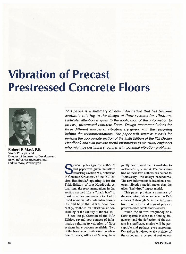
Vibration of Precast Prestressed Concrete Floors
Robert F. Mast, P.E. Senior Principal and Director of Engineering Development BERGER/ABAM Engineers, Inc. Federal Way, Washington
76
This paper is a summary of new information that has become available relating to the design of floor systems for vibration. Particular attention is given to the application of this information to precast, prestressed concrete floors. Design recommendations for three different sources of vibration are given, with the reasoning behind the recommendations. The paper will serve as a basis for revising the appropriate section of the Sixth Edition of the PC/ Design Handbook and will provide useful information to structural engineers who might be designing structures with potential vibration problems.
Several years ago, the author of this paper was given the task of rewriting Section 9.7, Vibration
in Concrete Structures, of the PCI Design Handbook, 1 updating it for the Fifth Edition of that Handbook. At that time, the recommendations in that section seemed like a "black box" to most structural engineers. One had to insert numbers into unfamiliar formulas, and hope that it was done correctly, without an intuitive understanding of the validity of the results.
Since the publication of the Fifth Edition, several new sources of information relating to vibration of floor systems have become available. Two of the best-known authorities on vibration of floors, Allen and Murray, have
jointly contributed their knowledge to References 2, 3, and 4. The collaboration of these two authors has helped to "demystify" the design procedures. The new information is based on a resonant vibration model, rather than the older "heel-drop" impact model.
This paper provides a summary of the new information contained in References 2 through 6, as the information relates to the design of precast, prestressed concrete floor systems.
When the natural frequency of a floor system is close to a forcing frequency, and the deflection of the system is significant, motion will be perceptible and perhaps even annoying. Perception is related to the activity of the occupant: a person at rest or en-
PCI JOURNAL
gaged in quiet work will tolerate less vibration than a person perfomring an active function, such as dancing or aerobics. If a floor system dissipates the imparted energy in a very short period of time, the motion is likely to be perceived as less annoying. Thus, the damping characteristics of the system affect acceptability.
Three separate sources of vibrations are discussed, and design recommendations are made for each. The first source relates to vibrations caused by individuals walking, the second relates to vibrations caused by individuals engaged in rhythmic activity, and the third relates to vibrations introduced by machinery.
Limits are stated as a minimum natural frequency of a structural system. These limits depend on the pemrissible peak accelerations (as a fraction of gravitational acceleration), on the mass affected by an activity, the environment in which the vibration occurs, the effectiveness of interaction between connected structural components, and the degree of damping, among others. Much vibration theory is derived from experience with steel and wood floors. In general, floor vibrations are much less likely to be a problem with stiffer, more massive concrete floors.
Some building types common in precast construction are not dealt with in the references that form the basis for this paper. For example, response to vehicular-induced vibrations in parking structures is not provided, because none of the source references cover this aspect. Choice of limits for usages not listed may be selected, with judgment, by comparison with other types listed here.
It must be emphasized that the calculations presented are very approximate. The actual natural frequency of a floor can be estimated to a reasonable degree of accuracy, but the calculation of the required frequency is based on damping and on human perception, both of which are subject to variation. When in doubt about the acceptability of a proposed floor system, the best way to decide is to compare it, using the same method of analysis, to existing similar systems that are known to be acceptable or unacceptable.
November-December 2001
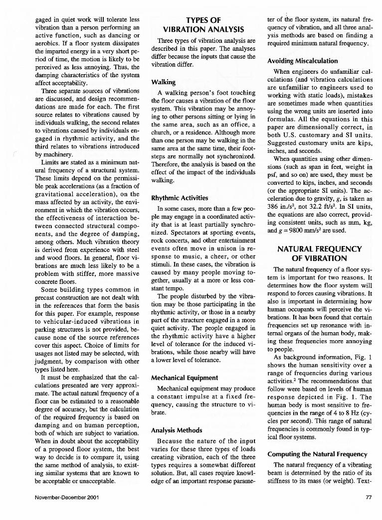
TYPES OF VIBRATION ANALYSIS
Three types of vibration analysis are described in this paper. The analyses differ because the inputs that cause the vibration differ.
Walking
A walking person's foot touching the floor causes a vibration of the floor system. This vibration may be annoying to other persons sitting or lying in the same area, such as an office, a church, or a residence. Although more than one person may be walking in the same area at the same time, their footsteps are normally not synchronized. Therefore, the analysis is based on the effect of the impact of the individuals walking.
Rhythmic Activities
In some cases, more than a few people may engage in a coordinated activity that is at least partially synchronized. Spectators at sporting events, rock concerts, and other entertainment events often move in unison in response to music, a cheer, or other stimuli. In these cases, the vibration is caused by many people moving together, usually at a more or less constant tempo.
The people disturbed by the vibration may be those participating in the rhythmic activity, or those in a nearby part of the structure engaged in a more quiet activity. The people engaged in the rhythmic activity have a higher level of tolerance for the induced vibrations, while those nearby will have a lower level of tolerance.
Mechanical Equipment
Mechanical equipment may produce a constant impulse at a fixed frequency, causing the structure to vibrate.
Analysis Methods
Because the nature of the input varies for these three types of loads creating vibration, each of the three types requires a somewhat different solution. But, all cases require knowledge of an important response parame-
ter of the floor system, its natural frequency of vibration, and all three analysis methods are based on finding a required minimum natural frequency.
Avoiding Miscalculation
When engineers do unfamiliar calculations (and vibration calculations are unfamiliar to engineers used to working with static loads), mistakes are sometimes made when quantities using the wrong units are inserted into formulas. All the equations in this paper are dimensionally correct, in both U.S. customary and SI units. Suggested customary units are kips, inches, and seconds.
When quantities using other dimensions (such as span in feet, weight in psf, and so on) are used, they must be converted to kips, inches, and seconds (or the appropriate SI units). The acceleration due to gravity, g, is taken as 386 in./s2
, not 32.2 ftls2• In SI units, the equations are also correct, providing consistent units, such as mm, kg, and g = 9800 mm/s2 are used.
NATURAL FREQUENCY OF VIBRATION
The natural frequency of a floor system is important for two reasons. It determines how the floor system will respond to forces causing vibrations. It also is important in determining how human occupants will perceive the vibrations. It has been found that certain frequencies set up resonance with internal organs of the human body, making these frequencies more annoying to people.
As background information, Fig. 1 shows the human sensitivity over a range of frequencies during various activities.2 The recommendations that follow were based on levels of human response depicted in Fig. 1. The human body is most sensitive to frequencies in the range of 4 to 8Hz (cycles per second). This range of natural frequencies is commonly found in typical floor systems.
Computing the Natural Frequency
The natural frequency of a vibrating beam is determined by the ratio of its stiffness to its mass (or weight). Text-
77
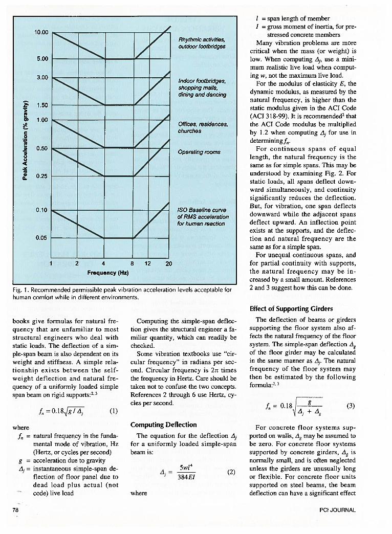
Fig. 1. Recommended permissible peak vibration acceleration levels acceptable forhuman comfort while in different environments.
span length of memberI = gross moment of inertia, for pre
stressed concrete membersMany vibration problems are more
critical when the mass (or weight) islow. When computing A, use a minimum realistic live load when computing w, not the maximum live load.
For the modulus of elasticity E, thedynamic modulus, as measured by thenatural frequency, is higher than thestatic modulus given in the ACT Code(ACT 318-99). It is recommended2thatthe ACT Code modulus be multipliedby 1.2 when computing A for use indeterminingf.
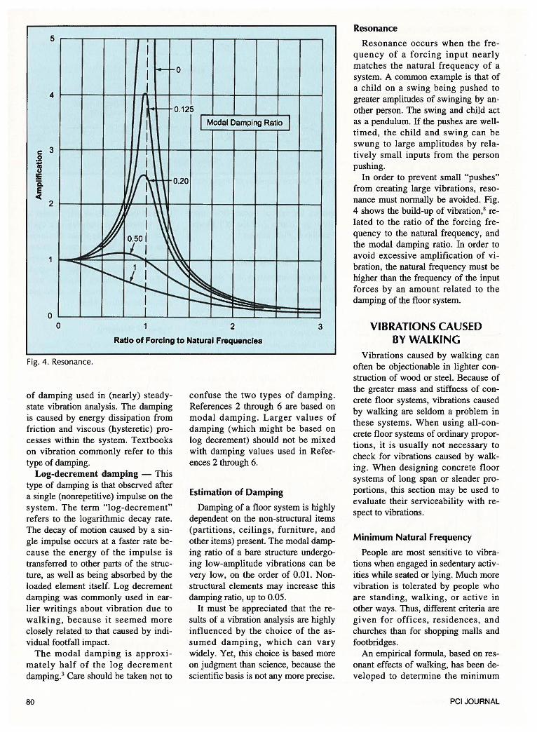
For continuous spans of equallength, the natural frequency is thesame as for simple spans. This may beunderstood by examining Fig. 2. Forstatic loads, all spans deflect downward simultaneously, and continuitysignificantly reduces the deflection.But, for vibration, one span deflectsdownward while the adjacent spansdeflect upward. An inflection pointexists at the supports, and the deflection and natural frequency are thesame as for a simple span.
For unequal continuous spans, andfor partial continuity with supports,the natural frequency may be increased by a small amount. References2 and 3 suggest how this can be done.
Effect of Supporting Girders
books give formulas for natural frequency that are unfamiliar to moststructural engineers who deal withstatic loads. The deflection of a simple-span beam is also dependent on itsweight and stiffness. A simple relationship exists between the self-weight deflection and natural frequency of a uniformly loaded simplespan beam on rigid supports:2’3
where
f, =O.18gI/i, (1)
f,, = natural frequency in the fundamental mode of vibration, Hz(Hertz, or cycles per second)
g = acceleration due to gravity= instantaneous simple-span de
flection of floor panel due todead load plus actual (notcode) live load
78
Computing the simple-span deflection gives the structural engineer a familiar quantity, which can readily bechecked.
Some vibration textbooks use “circular frequency” in radians per second. Circular frequency is 27t timesthe frequency in Hertz. Care should betaken not to confuse the two concepts.References 2 through 6 use Hertz, cycles per second.
Computing Deflection
The equation for the deflectionfor a uniformly loaded simple-spanbeam is:
where
A5w14
— 384E1
The deflection of beams or girderssupporting the floor system also affects the natural frequency of the floorsystem. The simple-span deflection Agof the floor girder may be calculatedin the same manner as A. The naturalfrequency of the floor system maythen be estimated by the followingformula:2’3
f=0.18I gAj+Ag
(3)
For concrete floor systems supported on walls, 4g may be assumed tobe zero. For concrete floor systemssupported by concrete girders, Ag iS
normally small, and is often neglected
(2) unless the girders are unusually longor flexible. For concrete floor unitssupported on steel beams, the beamdeflection can have a significant effect
Rhythmic activities,outdoor footbridges
10,00
5.00
3.00
1.50
1,00
0.50
0.25
0.10
Indoor footbridges,shopping malls,dining and dancing
>a,a,
0
a,a’C.,C.,
a,a’
Offices, residences,churches
Operating rooms
0.05
ISO Baseline curveof RMS accelerationfor human reaction
1 2 4 8 12Frequency (Hz)
20
PCI JOURNAL
on the behavior, and should usually beincluded in the computation forf.
Minimum Natural Frequency
Floors with natural frequencieslower than 3 Hz are not recommended3because they are subject to “roguejumping.” Rogue jumping occurs whenpeople discover that they can cause vibrations to build up by jumping at thefloor’s natural frequency. They maythen decide to see how large a vibration they can induce. But, it has beenfound that people have difficulty synchronizing their jumping at frequenciesgreater than 3 Hz.
Graphs of Natural Frequency
Eqs. (1) and (2) may be combined toproduce the following Eq. (4) for afloor unit on stiff supports:
f, = (l.58112)...JEIg/w
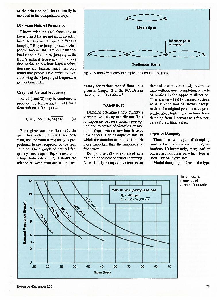
For a given concrete floor unit, thequantities under the radical are constant, and the natural frequency is proportional to the reciprocal of the spansquared. On a graph of natural frequency versus span, Eq. (4) results ina hyperbolic curve. Fig. 3 shows therelation between span and natural fre
quency for various topped floor unitsgiven in Chapter 2 of the PCI DesignHandbook, Fifth Edition.’
DAMPINGDamping determines how quickly a
(4) vibration will decay and die out. Thisis important because human perception and tolerance of vibration or motion is dependent on how long it lasts.Seasickness is an example of this, inwhich the duration of motion is muchmore important than the amplitude orfrequency.
Damping usually is expressed as afraction or percent of critical damping.A critically damped system is so
damped that motion slowly returns tozero without ever completing a cycleof motion in the opposite direction.This is a very highly damped system,in which the motion slowly creepsback to the original position asymptotically. Real building structures havedamping from 1 percent to a few percent of the critical value.
Types of Damping
There are two types of dampingused in the literature on building vibrations. Unfortunately, many earlierpapers are not clear on which type isused. The two types are:
Modal damping — This is the type
November-December 2001
Fig. 3. Naturalfrequency ofselected floor units.
Simple Span
—Inflection pointat support
Continuous Spans
Fig. 2. Natural frequency of simple and continuous spans.
12
10
C’,
I
>‘UCw0•
U..
(0
(0z3
2
020 25 30 35 40 45 50 55 60 65 70
Span (feet)
79
5
4
I I f-~o I I
1r-- o.125
1 l Modal Damping Ratio I
c 3 0
1 !E a. ~
2
0
I I
i ~m 020
0 2 3
Ratio of Forcing to Natural Frequencies
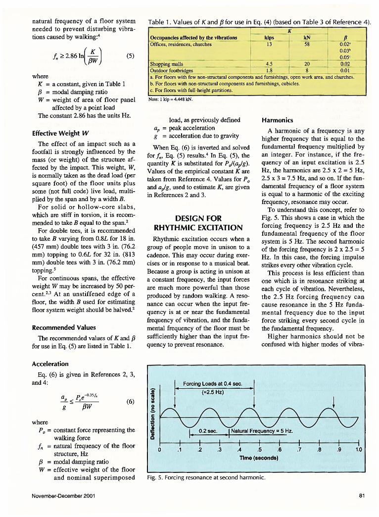
Fig. 4. Resonance.
of damping used in (nearly) steadystate vibration analysis. The damping is caused by energy dissipation from friction and viscous (hysteretic) processes within the system. Textbooks on vibration commonly refer to this type of damping.
Log-decrement damping - This type of damping is that observed after a single (nonrepetitive) impulse on the system. The term "log-decrement" refers to the logarithmic decay rate. The decay of motion caused by a single impulse occurs at a faster rate because the energy of the impulse is transferred to other parts of the structure, as well as being absorbed by the loaded element itself. Log decrement damping was commonly used in earlier writings about vibration due to walking, because it seemed more closely related to that caused by individual footfall impact.
The modal damping is approximately half of the log decrement damping. 3 Care should be taken not to
80
confuse the two types of damping. References 2 through 6 are based on modal damping. Larger values of damping (which might be based on log decrement) should not be mixed with damping values used in References 2 through 6.
Estimation of Damping
Damping of a floor system is highly dependent on the non-structural items (partitions, ceilings, furniture, and other items) present. The modal damping ratio of a bare structure undergoing low-amplitude vibrations can be very low, on the order of 0.01. Nonstructural elements may increase this damping ratio, up to 0.05.
It must be appreciated that the results of a vibration analysis are highly influenced by the choice of the assumed damping, which can vary widely. Yet, this choice is based more on judgment than science, because the scientific basis is not any more precise.
Resonance
Resonance occurs when the frequency of a forcing input nearly matches the natural frequency of a system. A common example is that of a child on a swing being pushed to greater amplitudes of swinging by another person. The swing and child act as a pendulum. If the pushes are welltimed, the child and swing can be swung to large amplitudes by relatively small inputs from the person pushing.
In order to prevent small "pushes" from creating large vibrations, resonance must normally be avoided. Fig. 4 shows the build-up of vibration, 8 related to the ratio of the forcing frequency to the natural frequency, and the modal damping ratio. In order to avoid excessive amplification of vibration, the natural frequency must be higher than the frequency of the input forces by an amount related to the damping of the floor system.
VIBRATIONS CAUSED BY WALKING
Vibrations caused by walking can often be objectionable in lighter construction of wood or steel. Because of the greater mass and stiffness of concrete floor systems, vibrations caused by walking are seldom a problem in these systems. When using all-concrete floor systems of ordinary proportions, it is usually not necessary to check for vibrations caused by walking. When designing concrete floor systems of long span or slender proportions, this section may be used to evaluate their serviceability with respect to vibrations.
Minimum Natural Frequency
People are most sensitive to vibrations when engaged in sedentary activities while seated or lying. Much more vibration is tolerated by people who are standing, walking, or active in other ways. Thus, different criteria are given for offices, residences, and churches than for shopping malls and footbridges.
An empirical formula, based on resonant effects of walking, has been developed to determine the minimum
PCI JOURNAL
natural frequency of a floor system needed to prevent disturbing vibrations caused by walking:4
f.~ 2.86ln(~) (5)
where K = a constant, given in Table 1 f3 = modal damping ratio W = weight of area of floor panel
affected by a point load The constant 2.86 has the units Hz.
Effective Weight W
The effect of an impact such as a footfall is strongly influenced by the mass (or weight) of the structure affected by the impact. This weight, W, is normally taken as the dead load (per square foot) of the floor units plus some (not full code) live load, multiplied by the span and by a width B.
For solid or hollow-core slabs, which are stiff in torsion, it is recommended to take B equal to the span.2
For double tees, it is recommended to take B varying from 0.8L for 18 in. (457 mm) double tees with 3 in. (76.2 mm) topping to 0.6L for 32 in. (813 mm) double tees with 3 in. (76.2 mm) topping.5
For continuous spans, the effective weight W may be increased by 50 percent. 2•3 At an unstiffened edge of a floor, the width B used for estimating floor system weight should be halved. 2
Recommended Values
The recommended values of K and f3 for use in Eq. (5) are listed in Table 1.
Acceleration
Eq. (6) is given in References 2, 3, and4:
where
a p -0.35/n ___g_ < _,_oe-:---g - {3W
(6)
P 0 = constant force representing the walking force
fn = natural frequency of the floor structure, Hz
f3 = modal damping ratio W = effective weight of the floor
and nominal superimposed
November-December 2001
j__f!__ Occupancies affected by the vibrations __ _ Offices, residences, churches
K _ -:-:-:--kips I kN 13 --58 0.02"
I 0.03b .______Q,05'
Sho in.&_m~ -~~~-- ~ 20 _J_ 0.~ Outdoorfootbridges 1.8 __L__ 8 0.01 a. For floors with few ~ctural components and furnishings, open work area, and churches. b. For floors with non-structural components and furnishings, cubicles. c. For floors with full-height partitions.
Note: I kip = 4.448 leN.
load, as previously defined aP = peak acceleration g = acceleration due to gravity
When Eq. (6) is inverted and solved for fm Eq. (5) results.4 In Eq. (5), the quantity K is substituted for P J(aplg). Values of the empirical constant K are taken from Reference 4. Values for Po and aplg, used to estimate K, are given in References 2 and 3.
DESIGN FOR RHYTHMIC EXCITATION Rhythmic excitation occurs when a
group of people move in unison to a cadence. This may occur during exercises or in response to a musical beat. Because a group is acting in unison at a constant frequency, the input forces are much more powerful than those produced by random walking. A resonance can occur when the input frequency is at or near the fundamental frequency of vibration, and the fundamental frequency of the floor must be sufficiently higher than the input frequency to prevent resonance.
Forcing Loads at 0.4 sec.
(=2.5 Hz)
0 .1 .2 .3 .4
Harmonics
A harmonic of a frequency is any higher frequency that is equal to the fundamental frequency multiplied by an integer. For instance, if the fre quency of an input excitation is 2.5 Hz, the harmonics are 2.5 x 2 = 5 Hz, 2.5 x 3 = 7.5 Hz, and so on. If the fundamental frequency of a floor system is equal to a harmonic of the exciting frequency, resonance may occur.
To understand this concept, refer to Fig. 5. This shows a case in which the forcing frequency is 2.5 Hz and the fundamental frequency of the floor system is 5 Hz. The second harmonic of the forcing frequency is 2 x 2.5 = 5 Hz. In this case, the forcing impulse strikes every other vibration cycle.
This process is less efficient than one which is in resonance striking at each cycle of vibration. Nevertheless, the 2 .5 Hz forcing frequency can cause resonance in the 5 Hz fundamental frequency due to the input force striking every second cycle in the fundamental frequency.
Higher harmonics should not be confused with higher modes of vibra-
Time (seconds)
Fig. 5. Forcing resonance at second harmonic.
81
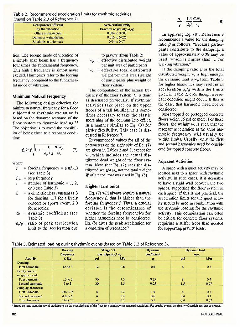
Table 2. Recommended acceleration limits for rhythmic activities (based on Table 2.3 of Reference 2). (8)
Occupancies affected ~ the vibration
Office or residential_
tion. The second mode of vibration of a simple span beam has a frequency four times the fundamental frequency. This high a frequency is almost never excited. Harmonics refer to the forcing frequency, compared to the fundamental mode of vibration.
Minimum Natural Frequency
The following design criterion for minimum natural frequency for a floor subjected to rhythmic excitation is based on the dynamic response of the floor system to dynamic loading.2•3
The objective is to avoid the possibility of being close to a resonant condition:
1 + _k_a;wp f. "?.f ao I g w,
(7)
where f = forcing frequency = (i)lfsrep)
(see Table 3) fsrep = step frequency
= number of harmonic = 1, 2, or 3 (see Table 3)
k = a dimensionless constant ( 1.3 for dancing, 1.7 for a lively concert or sports event, 2.0 for aerobics)
ai = dynamic coefficient (see Table 3)
aJg = ratio of peak acceleration limit to the acceleration due
Acceleration limit, Fraction of ravity, a,jg
_____ _ O.QQ4 to 0.007
O.QJ1_to_Q;..025 _ 0.04 to 0.07
to gravity (from Table 2) wP = effective distributed weight
per unit area of participants w1 = effective total distributed
weight per unit area (weight of participants plus weight of floor system)
The computation of the natural frequency of the floor system, fm is done as discussed previously. If rhythmic activities take place on the upper floors of a tall building, it is sometimes necessary to take the elastic shortening of the columns into effect, in a manner similar to Eq. (3) for girder flexibility. This case is discussed in Reference 7.
Recommended values for all of the parameters on the right side of Eq. (7) are given in Tables 2 and 3, except for w 1, which includes the actual distributed dead weight of the floor system. Note that Eq. (7) uses the distributed weight w,, not the total weight W of a panel that was used in Eq. (5).
Higher Harmonics
Eq. (7) will always require a natural frequency fn that is higher than the forcing frequency f. Thus, a crucial decision is the determination of whether the forcing frequencies for higher harmonics need be considered. Eq. (8) gives the peak acceleration for a condition of resonance:3
In applying Eq. (8), Reference 3 recommends a value for the damping ratio f3 as follows. "Because participants contribute to the damping, a value of approximately 0.06 may be used, which is higher than ... for walking vibration."
If the damping ratio f3 or the total distributed weight w, is high enough, the dynamic load aiwp from Table 3 for higher harmonics may result in an acceleration a of g within the limits given in Table 2, even though a resonant condition might occur. If this is the case, that harmonic need not be considered.
Most topped or pretopped concrete floors weigh 75 psf or more. For these floors, the weight w, is such that the resonant acceleration at the third harmonic frequency will usually be within limits. Usually, only the first and second harmonics need be considered for topped concrete floors.
Adjacent Activities
A space with a quiet activity may be located next to a space with rhythmic activity. In such cases, it is desirable to have a rigid wall between the two spaces, supporting the floor system in each space. If this is not practical, the acceleration limits for the quiet activity should be used in combination with the rhythmic loading for the rhythmic activity. This combination can often be critical for concrete floor systems, requiring a stiffer floor than needed for supporting gravity loads.
Table 3. Estimated loading during rhythmic events (based on Table 5.2 of Reference 3).
Forcing Weight of Dynamic Dynamic load frequency participants,* Wp 'I coefficient (l;Wp
Activity f,Hz psf kPa a; psf kPa ----·
Dancing: I First harmonic 1.5 to 3 12 0.6 0.5 6 0.3 --- ·- -- - -Lively concert or sports event:
First harmonic 1.5 to 3 30 1.5 0.25 8 0.4 Second harmonic _ i-- 3 !9 5 30 1.5 0.05 I 1.5 0.07
Jumping exercises: i
First harmonic 2to 2.75 4 0.2 1.5 6 0.3 Second harmonic 4 to 5.5 4 0.2
I 0.6 2.4 0.1
Third harmonic 6 to 8.25 4 0.2 I 0.1 0.4 0.02
* Based on maximum density of participants on the occupied area of the floor for commonly encountered conditions. For special events, the density of participants can be greater.
82 PCI JOURNAL
VIBRATION ISOLATION FOR MECHANICAL
EQUIPMENT Note: This section is taken from
Reference 1. It is included here for the sake of completeness.
Vibration produced by equipment with unbalanced operating or starting forces can usually be isolated from the structure by mounting on a heavy concrete slab placed on resilient supports. This type of slab, called an inertia block, provides a low center of gravity to compensate for thrusts, such as those generated by large fans.
For equipment with less unbalanced weight, a "housekeeping" slab is sometimes used below the resilient mounts to provide a rigid support for the mounts and to keep them above the floor so they are easier to clean and inspect. This slab may also be mounted on pads of precompressed glass fiber or neoprene.
The natural frequency of the total load on resilient mounts must be well below the frequency generated by the equipment. The required weight of an inertia block depends on the total weight of the machine and the unbalanced force. For a long-stroke compressor, five to seven times its weight might be needed. For high pressure fans, one to five times the fan weight is usually sufficient.
A floor supporting resiliently mounted equipment must be stiffer than the isolation system. If the static deflection of the floor approaches the static deflection of the mounts, the floor becomes a part of the vibrating system, and little vibration isolation is achieved. In general, the floor deflection should be limited to about 15 percent of the deflection of the mounts.
Simplified theory shows that for 90 percent vibration isolation, a single resilient supported mass (isolator) should have a natural frequency of about one-third the driving frequency of the equipment. The natural frequency of this mass can be calculated by Eq. (9):
fn = 0.16~g I 11i (9)
where fn = natural frequency of the isola
tor, Hz
November-December 2001
11; = static deflection of the isolator, in.
Note that the coefficient 0.16 differs from the coefficient 0.18 in Eq. (1). Eq. (9) is for a lump mass; Eq. (1) is for a distributed mass in a beam.
From the above, the required static deflection of an isolator can be determined as follows:
In= fd I 3 = 0.16~g I 11i
L\ = 0.23g I!/
and
or
(10)
11!=:> 0.15 11; (11)
where !d = driving frequency of the
equipment, Hz 111 = static deflection of the floor
system caused by the weight of the equipment, including inertia block, at the location of the equipment, in.
REAL-WORLD OBSERVATIONS
The author has experienced concern over the apparent flexibility of precast floor units while stored on dunnage. But, he has found the same units to appear much less flexible once they were installed in a building, and interconnected to adjacent members. Concrete members have a high torsional rigidity that enables them to distribute loads laterally more effectively than does bridging in other materials. The author believes this helps prevent serious resonant conditions from occurring in interconnected concrete floors.
A football stadium was constructed using individual 2 ft (0.6 m) wide channel slabs for each row of seats. The natural frequency of the channel slabs was 4.2 Hz. The required minimum natural frequency using Eq. (7) was 4.2 Hz for the first harmonic and 5.8 Hz for the second harmonic. When first installed, connections to adjacent channel slabs at the quarter points of the span were not completed.
Spectators complained about the perceptible movements of the channel slabs. Then, the weld connections at
the quarter points were completed. Subsequently, the performance was satisfactory. Apparently, the interconnection suppressed response in the second harmonic, and reduced the response in the first harmonic.
The seat slabs of Example 2 have been used on three major stadiums in service since 1990. The span is 43 ft (13.1 m) in rectangular bays, with a maximum span of 50ft (15.2 m) in angled bays. Performance is satisfactory, despite the fact that Example 2 shows the maximum span to be 43 ft (13.1 m), and only 36 ft (11.0 m) when the second harmonic is considered.
Apparently, the second harmonic is not being excited, and the first harmonic response is reduced in the angled bays, in which each of the interconnected seat slab sections has a different natural frequency. This helps prevent a resonant response.
Footbridges have little, if any, interconnection with adjacent members. The response of a footbridge resembles that of an individual member stored on temporary supports more than that of an integrated floor system. Footbridges need to be conservatively designed.
The author and the PCI Industry Handbook Committee would greatly appreciate hearing about real-world experiences relating to objectionable vibration (or lack of such) in concrete floor systems.
CONCLUDING REMARKS Methods of vibration analysis for
three sources of vibration have been presented. All three cases are taken from existing publications, and all three depend upon finding the natural frequency of vibration of the floor system.
In addition to showing the reader how the analyses are done, this paper has attempted to show the reader why various aspects of the analysis process are important.
The author once again reminds the reader that the recommendations for acceptability are based on human perception, which is very subjective. Thus, the numerical results cannot be applied as rigidly as those of, say, a strength analysis.
83
REFERENCES
The following is a brief listing of references, many of which have been published since the writing of the Fifth Edition of the PCI Design Handbook. Reference 3 gives a more comprehensive listing of references on the subject of floor vibrations. A brief description follows below the listing of each reference.
1. PCI Industry Handbook Committee, PC/ Design Handbook -Precast and Prestressed Concrete, Fifth Edition, Precast/Prestressed Concrete Institute, Chicago, IL, 1999.
2. ATC, "ATC Design Guide 1, Minimizing Floor Vibration," Applied Technology Council, Redwood City, CA, 1999, 49 pp.
(This guide covers the design of wood, steel, and concrete floors. The approach given is straightforward, and is compatible with References 3, 4, and 6.) 3. AISC/OSC, "Steel Design Guide Series 11, Floor Vibrations
Due to Human Activity," American Institute of Steel Construction, Chicago, IL, 1997.
(This is a comprehensive reference covering the design of steel floor systems subjected to vibrations from human activity. It is generally applicable to concrete floors as well.) 4. Allen, D. E., and Murray, T. M., "Design Criterion for Vibra-
tions Due to Walking," Engineering Journal, Fourth Quarter, American Institute of Steel Construction, 1993, pp. 117-129.
(This paper discusses the origin of Eqs. 9.7.3 and 9.7.4.) 5. Chen, Y., and Aswad, A., "Vibration Characteristics of Double
Tee Building Floors," PCI JOURNAL, V. 37, No. 1, JanuaryFebruary 1994, pp. 84-95.
(This paper examined practical spans ranging from 30 to 72ft (9.1 to 22 m) for topped floor double tees, and evaluated them using four different published criteria. It was concluded that the spans examined have satisfactory performance when subjected to walking inputs, provided the modal damping ratio is at least 0.03.) 6. Murray, T. M., "Floor Vibrations: Tips for Designers of Office
Buildings," Structure, Fall 2000, National Council of Structural Engineers, pp. 26-30.
(This article gives practical advice on designing steel floors. The advice also applies to concrete floors.) 7. Allen, D. E., "Building Vibrations From Human Activities,"
Concrete International, V. 12, No.6, June 1990, pp. 66-73. 8. Den Hartog, J.P., Mechanical Vibrations, Dover, 1956. (This is a classic text on vibration.) 9. Harris, C. M., and Crede, C. E., Shock and Vibration Hand
book, Second Edition, McGraw-Hill Book Co., New York, NY, 1976.
APPENDIX A- NOTATION
ao = acceleration limit Po = constant force representing the walking force
aP = peak acceleration w = weight of area of floor panel affected by a point B = width of floor affected by a point load load E = dynamic modulus of elasticity = 1.2 x static modu- w = uniform load, per unit length
Ius per ACI 318 Wp = effective distributed weight of participants per unit f = forcing frequency, Hz= (i)lfsrep), see Table 3 area
!d driving frequency of the equipment, Hz Wr = effective total distributed weight per unit area fn = natural frequency in the fundamental mode of vi- (weight of participant plus weight of floor system)
bration, Hz (cycles per second) ai = dynamic coefficient (see Table 3)
!step = step frequency f3 = modal damping ratio (fraction of critical damping) g = acceleration due to gravity, 386 in./s2 (9800 Lit = static deflection of the floor system caused by the
mmJs2) weight of the equipment, including inertial block, I = gross moment of inertia for prestressed concrete at the location of the equipment
members L1g = instantaneous deflection of a supporting girder number of harmonic (see Table 3) L1i = static deflection of isolator
K = a constant, given in Table 1 L1j = instantaneous simple-span deflection of a floor k = a dimensionless constant (1.3 for dancing, 1.7 for panel due to dead load plus actual (not code) live
lively concert or sports event, 2.0 for aerobics) load = span length
84 PCI JOURNAL
APPENDIX B — DESIGN EXAMPLES
Example 1. Vibrations Caused by WalkingGiven: 1ODT32+2 (see p. 2-15 of Reference 1)
Open office area: 60 ft span
Problem: Check for vibration caused by walking.
Solution: Use Eq. (5) to find minimum requiredf:
f, 2.86
Estimate j3 = 0.02 (Table 1)K= 13 kips (Table 1)Estimate effective weight Ww = 89 psf (p. 2-15 of Reference 1) + 10 psfassumed superimposed load = 99 psfEstimate effective width B = 0.6 L = 36 ftW = w(B)(L) = 0.099 ksf (36 ft)(60 ft) = 214 kipsNote that in this case, it was not necessary toconvert ft to in. because the ft units cancel out.
Minimum requiredf =
2.86Hzln(13k
‘1=3.18Hz\0.02x2l4k}
From Fig. 3, for 10DT32+2 on 60 ft spanProvidedf = 3.8 Hz>3.18 OK
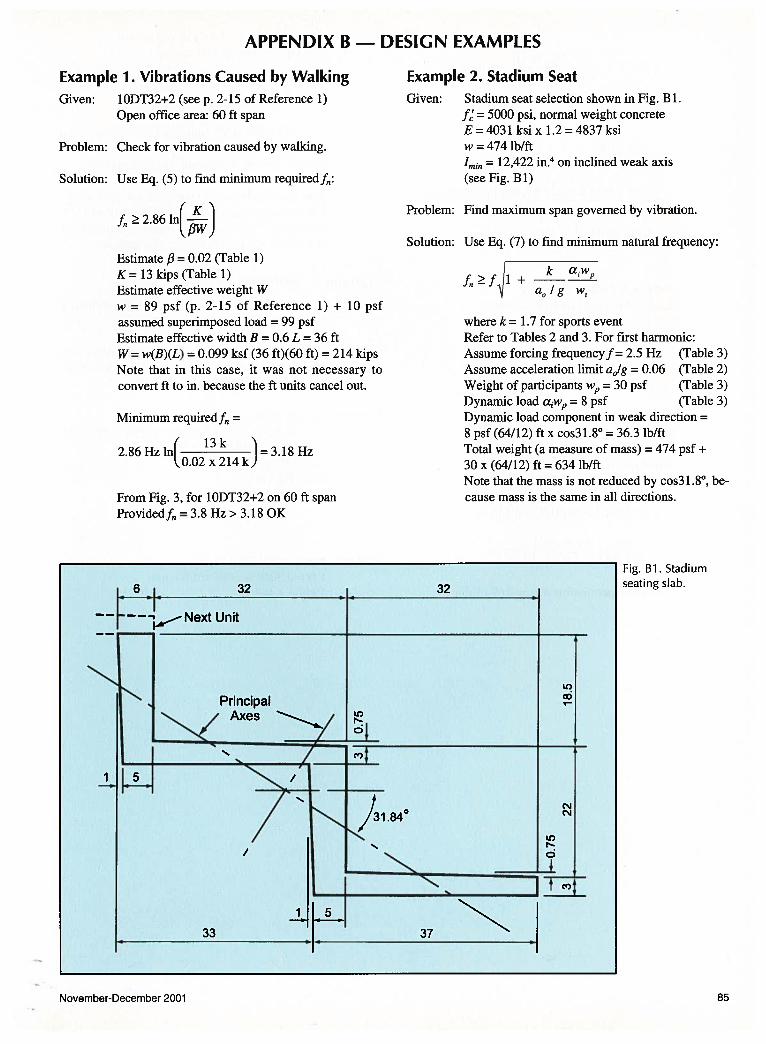
Example 2. Stadium SeatGiven: Stadium seat selection shown in Fig. B 1.
f’ = 5000 psi, normal weight concreteE=403l ksix 1.2=4837ksiw = 474 lb/ft
‘mEn = 12,422 in.4 on inclined weak axis(see Fig. Bi)
Problem: Find maximum span governed by vibration.
Solution: Use Eq. (7) to find minimum natural frequency:
ffl+k aw
a0/g w
where k = 1.7 for sports eventRefer to Tables 2 and 3. For first harmonic:Assume forcing frequencyf= 2.5 Hz (Table 3)Assume acceleration limit a0Ig = 0.06 (Table 2)Weight of participants w = 30 psf (Table 3)Dynamic load cw = 8 psf (Table 3)Dynamic load component in weak direction =8 psf (64/12) ft x cos3l.8° = 36.3 lb/ftTotal weight (a measure of mass) 474 psf +
30 x (64/12) ft = 634 lb/ftNote that the mass is not reduced by cos3 1.8°, because mass is the same in all directions.
Fig. WI. Stadiumseating slab.
November-December 2001 85
86
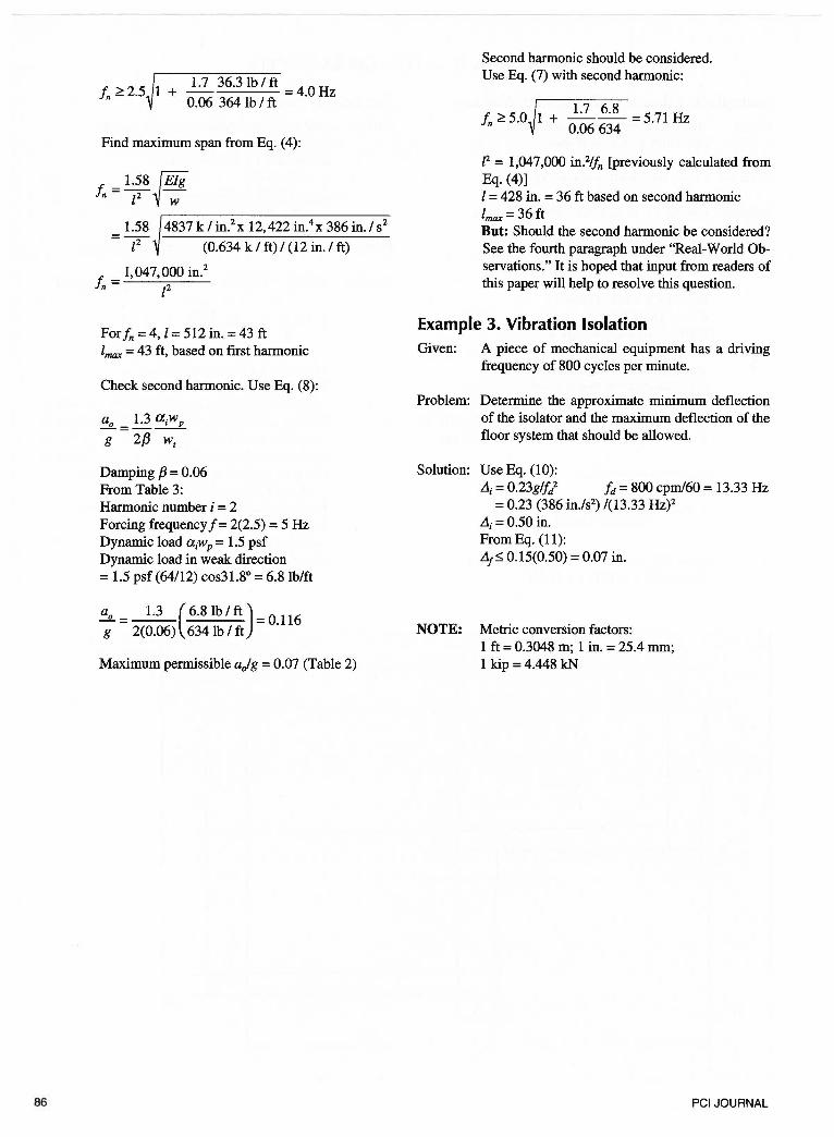
!, 2 5 1 1.7 36.3 lb I ft = 4.0 Hz n ~ • +
0.06 364 lb I ft
Find maximum span from Eq. (4):
!, = 1.58 ~ Elg n [2 W
1.58 4837 k I in.2 x 12,422 in.4 x 386 in. I s2
= f (0.634 k I ft) I (12 in. I ft)
!, = 1,047,000 in.2
n z2
Forfn = 4, l = 512 in.= 43ft lmax = 43 ft, based on first harmonic
Check second harmonic. Use Eq. (8):
ao =~ aiwp g 2{3 w1
Damping f3 = 0.06 From Table 3: Harmonic number i = 2 Forcing frequency f = 2(2.5) = 5 Hz Dynamic load aiwp = 1.5 psf Dynamic load in weak direction = 1.5 psf (64112) cos31.8° = 6.8lblft
ao = 1.3 (6.8lblft)=O.l16 g 2(0.06) 634 lb I ft
Maximum permissible ajg = 0.07 (Table 2)
Second harmonic should be considered. Use Eq. (7) with second harmonic:
!, ~ 5.0 1 + __!:Z_ 6·8
= 5.71 Hz n 0.06 634
P = 1,047,000 in.21fn [previously calculated from Eq. (4)] l = 428 in. = 36 ft based on second harmonic lmax =36ft But: Should the second harmonic be considered? See the fourth paragraph under "Real-World Observations." It is hoped that input from readers of this paper will help to resolve this question.
Example 3. Vibration Isolation
Given: A piece of mechanical equipment has a driving frequency of 800 cycles per minute.
Problem: Determine the approximate minimum deflection of the isolator and the maximum deflection of the floor system that should be allowed.
Solution: Use Eq. (10): L1i = 0.23glfi !d = 800 cpm/60 = 13.33 Hz
= 0.23 (386 in./s2) 1(13.33 Hz)2
L1i = 0.50 in. From Eq. (11): L1t:5: 0.15(0.50) = 0.07 in.
NOTE: Metric conversion factors: 1 ft = 0.3048 m; 1 in. = 25.4 mm; 1 kip = 4.448 kN
PCI JOURNAL