Embed Size (px)
Citation preview

3,209,448 Oct. 5, 1965 J. B. JONES
VIBRATORY WELDING METHOD AND APPARATUS
4 Sheets-Sheet 1 Filed March 12, 1962
N
INVENTOR. JAMES BYRON JONES
ATTORNEY

3,209,448 Oct. 5, 1965 J. B. JONES
VIBRATORY WELDING METHOD AND APPARATUS
4 Sheets-Sheet 2 Filed March 12, 1962
IN VENTOR.
JAMES 8YRO/V JONES BY
Mop/w ATTORNEY

3,209,448 J. B. JONES Oct. 5, 1965 VIBRATORY WELDING METHOD AND APPARATUS _
4 Sheets-Sheet 3 Filed March 12, 1962
j” F/G.4
M28
II will
64
INVENTOR. JAMES BYRON JONES
ATTORNEY

Oct. 5, 1965 J. B. JONES 3,209,448 VIBRATORY WELDING‘ METHOD AND APPARATUS
Filed March 12, 1962 4 Sheets-Sheet 4
INVENTOR.
JAMES BYRON JONES BY
WA/M ATTORNEY
United States Patent 0 " 1
‘3,209,448 VIBRATORY WELDING METHOD AND
, APPARATUS
James Byron Jones, West Chester, Pa., assignor, by mesne assignments, to Sonobond Corporation, West Chester, Pa., a corporation of Pennsylvania
Filed Mar. 12, 1962, Ser. No.\179,158 23 ‘Claims. (Cl. 29-4701)
This invention relates to vibratory welding, and more particularly, to an apparatus and method for elongated weld area vibratory welding.
In the packaging of many types of products, it is neces sary to hermetically seal the container. The hermetic seal of the container normally extends along an elongated area such as along the side or end of a pouch, packet, toothpaste tube, can, etc. Heretofore, the hermetic sealed elongated closure has been made by crimping, seal ing with cement or adhesive, heat sealing, sealing with plastic liners, etc. These closures have often been di?i cult, time consuming, and expensive to make, and are un— satisfactory for some applications. Hermetically-sealed elongated closures have been provided on containers such as can bodies, for example, by means of welding, solder ing, and other heat-sealing methods. However, these lat ter mentioned methods involve the use of considerable heat during the joining process. There are many types of containers, and/or products to be packaged, for which such closure methods are unsuitable because of the adverse effect of heat and/ or spatter or byproducts thereof.
In U. S. Patents 2,946,119; 2,946,120; and 2,985,984, there is disclosed apparatus and method for welding to gether workpieces by means of vibratory welding. Vi bratory welding offers a great many advantages for forming hermetically sealed closures. For example, vibratory welding does not involve the use of any special sealing or ?ller agents, there need to be no signi?cant deformation of the workpieces being welded together, and there is relatively little heat generated in the weld area (too little heat, for example, to develop a cast structure in metal or alloy weldments). In addition, vibratory welding provides joints of su?‘iciently high strength as may be required by a particular hermetically sealed closure. Moreover, little or no pre-weld or post-weld cleaning is usually required; special joint designs or post-weld clean ing is usually required; special joint designs are usually unnecessary; no high currents are needed, relatively low power from standard voltage sources being generally used; actuation of the equipment can be synchronized with existing machinery by many straightforward methods; the power source can be remotely located from the welding area; and relatively low equipment maintenance is involved.
Vibratory welds having an elongated weld area may be made with reference to the disclosures in the aforesaid patents. Thus, an elongated weld area can be achieved by consecutive partial overlapping of a series of spot-type vi bratory Welds. This method of obtaining an elongated weld area is often time consuming and expensive. On the other hand, continuous-seam vibratory welds having an elon gated weld area and made with roller-type apparatus are faster to make and neater in appearance than overlap ping spots, but reliable continuous-roller-seam welding involves complicated rotary and/or traversing mecha nisms. Neither the overlapping-spot-weld method nor the roller-seam weld method provides an elongated Weld area with a single or extremely short weld pulse interval, such as in a fraction of a second. ‘
It has been discovered that a vibratory weld having an elongated area of appreciable line-like length may be obtained with a single weld time pulse interval with a uni form quality of bond over the entire length of the weld.
10
15
20
25
35
40
45
50
55
65
70
3,209,448 Patented Oct. 5, 1965 ice 2
This has not been practical heretofore, in view of the state of the mechanical vibratory art in general, and in view of the stringent tolerances requisite in connection with the making of many types of elongated hermetically sealed closures.
‘It is an object of the present invention to provide a novel apparatus employing vibratory energy for elongated weld area welding.
It is another object of the present invention to provide a novel method employing vibratory energy for elongated weld area welding.
It is another object of the present invention to provide a novel apparatus and method for providing an elongated weld area vibratory weld.
It is another object of the present invention to provide a novel apparatus and method employing vibratory energy wherein an elongated weld area may be provided with a single pulse interval.
It is still another object of the present invention to pro vide a novel apparatus and method employing vibratory energy in the forming of ‘a hermetic seal on container bodies.
It is still another object of the present invention to pro vide a novel apparatus and method employing vibratory energy for welding wherein it is possible to apply different forces to maintain the workpieces in intimate contact at spaced points along the weld zone.
Other objects will appear hereinafter. For the purposes of illustrating the invention there is
shown in the drawings forms which .are presently pre ferred; it being understood, however, that this invention is not limited to the precise arrangement and instrumen talities shown. ‘FIGURE 1 is a top plan view of the apparatus of the
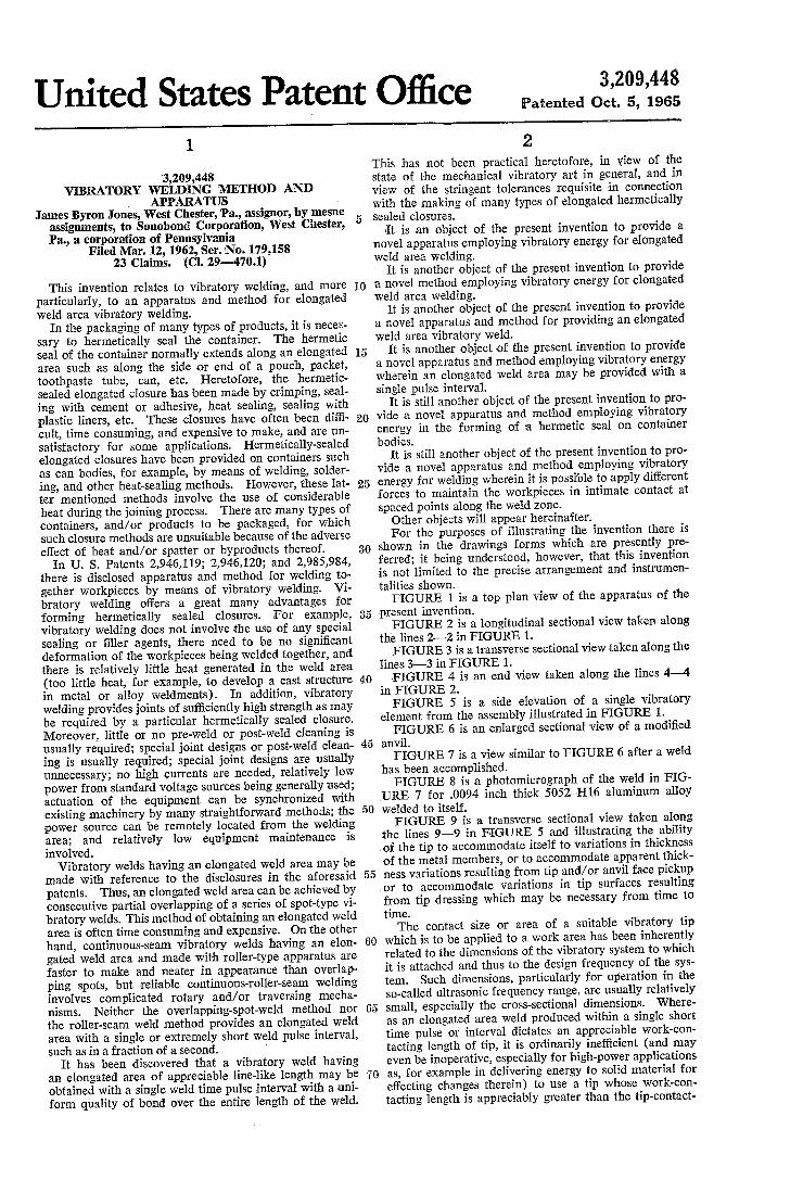
present invention. FIGURE 2 is a longitudinal sectional View taken along
the lines 2'—2 in FIGURE 1. FIGURE 3 is a transverse sectional view taken along the
lines 3-—-3 in FIGURE 1. ‘FIGURE 4 is an end view taken along the lines 4—4
in FIGURE 2. FIGURE 5 is a side elevation of a single vibratory
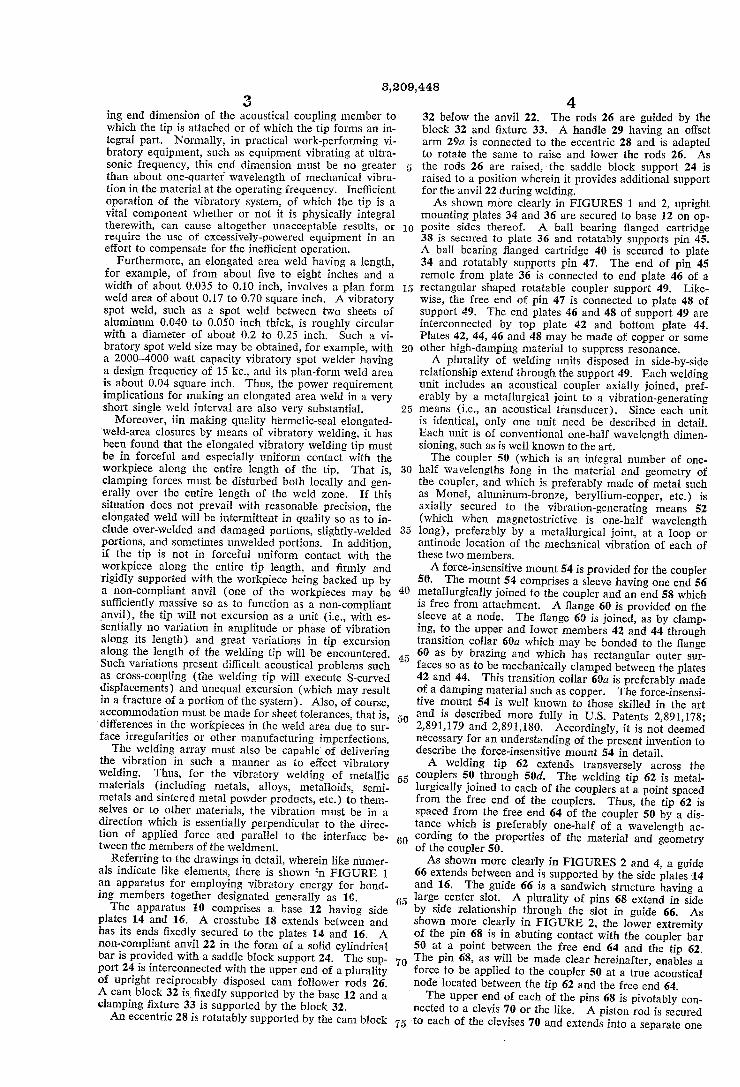
element from the assembly illustrated in FIGURE 1. FIGURE 6 is an enlarged sectional view of a modi?ed
anvil. FIGURE 7 is a view similar to FIGURE 6 after a weld
has been accomplished. FIGURE 8 is a photomicrograph of the weld in FIG
URE 7 for .0094 inch thick 5052~Hl6 aluminum alloy welded to itself. FIGURE 9 is a transverse sectional view taken along
the lines 9—9 in FIGURE 5 and illustrating the ability of the tip to accommodate itself to variations in thickness of the metal members, or to accommodate apparent thick ness variations resulting from tip and/ or anvil face pickup or to accommodate variations in tip surfaces resulting from tip dressing which may be necessary from time to time. The contact size or area of a suitable vibratory tip
which is to be applied to a work area has been inherently related to the dimensions of the vibratory system to which it is attached and thus to the design frequency of the sys tem. Such dimensions, particularly for operation in the so-called ultrasonic frequency range, are usually relatively small, especially the cross-sectional dimensions. Where as an elongated area weld produced within a single short time pulse or interval dictates an appreciable work-con tacting length of tip, it is ordinarily inef?cient (and may even be inoperative, especially for high-power applications as, for example in delivering energy to solid material for effecting changes therein) to use a tip whose work-con tacting length is appreciably greater than the tip-contact
3,209,448 3
ing end dimension of the acoustical coupling member to which the tip is attached or of which the tip forms an in tegral part. Normally, in practical work-performing vi bratory equipment, such as equipment vibrating at ultra sonic frequency, this end dimension must be no greater than about one-quarter wavelength of mechanical vibra tion in the material at the operating frequency. Ine?icient operation of the vibratory system, of which the tip is a vital component whether or not it is physically integral therewith, can cause altogether unacceptable results, or require the use of excessively-powered equipment in an effort to compensate for the inet?cient operation.
Furthermore, an elongated area weld having a length, for example, of from about ?ve to eight inches and a width of about 0.035 to 0.10 inch, involves a plan form weld area of about 0.17 to 0.70 square inch. A vibratory spot weld, such as a spot weld between two sheets of aluminum 0.040 to 0.050 inch thick, is roughly circular with a diameter of about 0.2 to 0.25 inch. Such 9. vi bratory spot weld size may be obtained, for example, with a 2000-4000 watt capacity vibratory spot welder having a design frequency of 15 kc., and its plan-form weld area is about 0.04 square inch. Thus, the power requirement implications for making an elongated area weld in a very short single weld interval are also very substantial.
Moreover, iin making quality hermetic-seal elongated weld-area closures by means of vibratory welding, it has been found that the elongated vibratory welding tip must be in forceful and especially uniform contact with the workpiece along the entire length of the tip. That is, clamping forces must be disturbed both locally and gen erally over the entire length of the weld zone. If this situation does not prevail with reasonable precision, the elongated weld will be intermittent in quality so as to in clude over-welded and damaged portions, slightly-welded portions, and sometimes unwelded portions. In addition, if the tip is not in forceful uniform contact with the workpiece along the entire tip length, and ?rmly and ‘rigidly supported with the workpiece being backed up by a non-compliant anvil (one of the workpieces may be sufficiently massive so as to function as a non-compliant anvil), the tip will not excursion as a unit (i.e., with es sentially no variation in amplitude or phase of vibration along its length) and great variations in tip excursion along the’ length of the welding tip will be encountered. Such variations present difficult acoustical problems such as cross-coupling (the welding tip will execute S-curved displacements) and unequal excursion (which may result in a fracture of a portion of the system). Also, of course, accommodation must be made for sheet tolerances, that is, ‘differences in the workpieces in the weld area due to sur face irregularities or other manufacturing imperfections. The welding array must also be capable of delivering
the vibration in such a manner as to effect vibratory welding. Thus, for the vibratory welding of metallic materials (including metals, alloys, metalloids, semi metals and sintered metal powder products, etc.) to them selves or to other materials, the vibration must be in a direction which is essentially perpendicular to the direc tion of applied force and parallel to the interface be tween the members of the weldment.
Referring to the drawings in detail, wherein like numer als indicate like elements, there is shown in FIGURE 1 an apparatus for employing vibratory energy for bond ing members together designated generally as 10. The apparatus 10 comprises a base 12 having side
plates 14 and 16. A crosstube 18 extends between and has its ends ?xedly secured to the plates 14 and 16. A non-compliant anvil 22 in the form of a solid cylindrical bar is provided with a saddle block support 24. The sup port 24 is interconnected with the upper end of a plurality of upright reciprocably disposed cam follower rods 26. A cam block 32 is ?xedly supported by the base 12 and a clamping ?xture 33 is supported by the block 32. An eccentric 28 is rotatably supported by the cam block
5
15
25
30
40
50
55
60
65
70
4 32 below the anvil 22. The rods 26 are guided by the block 32 and ?xture 33. A handle 29 having an offset arm 29a is connected to the eccentric 28 and is adapted to rotate the same to raise and lower the rods 26. As the rods 26 are raised, the saddle block support 24 is raised to a position wherein it provides additional support for the anvil 22 during welding. As shown more clearly in FIGURES 1 and 2, upright
mounting plates 34 and 36 are secured to base 12 on op posite sides thereof. A ball bearing ?anged cartridge 38 is secured to plate 36 and rotatably supports pin 45. A ball bearing ?anged cartridge 40 is secured to plate 34 and rotatably supports pin 47. The end of pin 45 remote from plate 36 is connected to end plate 46 of a rectangular shaped rotatable coupler support 49. Like wise, the free end of pin 47 is connected to plate 48 of support 49. The end plates 46 and 48 of support 49 are interconnected by top plate 42 and bottom plate 44. Plates 42, 44, 46 and 48 may be made of copper or some other high-damping material to suppress resonance. A plurality of welding units disposed in side-by-side
relationship extend through the support 49. Each welding unit includes an acoustical coupler axially joined, pref erably by a metallurgical joint to a vibration-generating means (i.e., an acoustical transducer). Since each unit is identical, only one unit need be described in detail. Each unit is of conventional one-half wavelength dimen sioning, such as is well known to the art. The coupler 50 (which is an integral number of one
half wavelengths long in the material and geometry of the coupler, and which is preferably made of metal such as Monel, aluminum-bronze, beryllium-copper, etc.) is axially secured to the vibration-generating means 52 (which when magnetostrictive is one-half wavelength long), preferably by a metallurgical joint, at a loop or antinode location of the mechanical vibration of each of these two members. A force-insensitive mount 54 is provided for the coupler
50. The mount 54 comprises a sleeve having one end 56 metallurgically joined to the coupler and an end 58 which is free from attachment. A ?ange 60 is provided on the sleeve at a node. The ?ange 60 is joined, as by clamp ing, to the upper and lower members 42 and 44 through transition collar 60a which may be bonded to the ?ange 60 as by brazing and which has rectangular outer sur faces so as to be mechanically clamped between the plates 42 and 44. This transition collar 60a is preferably made of a damping material such as copper. The force-insensi tive mount 54 is well known to those skilled in the art and is described more fully in US. Patents 2,891,178; 2,891,179 and 2,891,180. Accordingly, it is not deemed necessary for an understanding of the present invention to describe the force-insensitive mount 54 in detail. A welding tip 62 extends transversely across the
couplers 50 through 50d. The welding tip 62 is metal lurgically joined to each of the couplers at a point spaced from the free end of the couplers. Thus, the tip 62 is spaced from the free end 64 of the coupler 50 by a dis tance which is preferably one-half of a wavelength ac cording to the properties of the material and geometry of the coupler 50. As shown more clearly in FIGURES 2 and 4, a guide
66 extends between and is supported by the side plates 14 and 16. The guide 66 is a sandwich structure having a large center slot. A plurality of pins 68 extend in side by side relationship through the slot in guide 66. As shown more clearly in FIGURE 2, the lower extremity of the pin 68 is in abuting contact with the coupler bar 50 at a point between the free end 64 and the tip 62. The pin 68, as will be made clear hereinafter, enables a force to be applied to the coupler 50 at a true acoustical node located between the tip 62 and the free end 64. The upper end of each of the pins 68 is pivotably con
nected to a clevis 70 or the like. A piston rod is secured -to each-of the clevises 70 and extends into a separate one

3,209,448 5
of a plurality of piston cylinders 72 which correspond in number to the number of couplers. The uppermost end of the piston cylinders 72 are each pivotably secured to the crosstube 18. It will be appreciated that the conduits for supplying motivating ?uid (such as compressed air or oil under pressure) to the piston cylinders 72 have not been illustrated. When motivating ?uid is supplied to the piston cylinders 72, a force at the position and in the direction of arrow 74 may be applied to each of the couplers. ' '
The force applied in the direction and at the location of arrow 74 enables the couplers and the tip 62 to pivot about the longitudinal axis of the pins 45 and 47. The magnitude of the force 74 need only be su?icient so as to maintain the entire length of the tip 62 in contact with the overlapping edges of the members of the weldment, as, for example, the can body 76, so that said overlapping edges are maintained in intimate contact at the intended weld zone. The tip 62 has a length so that it extends slightly beyond each end of the weldment members, name 1y, can body 76, such as for a distance of approximately one-quarter inch. This length relationship provides a safety factor and assures that the overlapping edges of the members to be welded will be joined by a vibratory weld along its entire length. The cylindrically shaped can body 76 is held in a dis
position so that its overlapping free edges are below the tip 62 by a pair of pressure blocks 7 8 and 80. As shown more clearly in FIGURE 2, the pressure blocks 78 and 80 are provided with a concave surface juxtaposed to and spaced from the outer peripheral surface of the anvil 22. The pressure blocks 78 and 80, and their respective actua tors are identical. Accordingly, only the actuating mech anism of the pressure block 80 will be described in detail. The pressure block 80 is guided for reciprocatory move
ment toward and away from the anvil 22 by a T-shaped lug 82 which rides in and is guided by a T-shaped slot in‘ ?xture 33. Movement of block 80 is effected by a pres sure cylinder 91. The block 80 is connected to a variable chamber member such as a piston in cylinder 91 by means of a rod 92. The block 78 is actuated by cylinder 93. The cylinders 91 and 93 are supported in the posi
- tions illustrated by bracket arms 94 and 95, respectively, which extend between the side plates 14 and 16.
It will be noted that a groove is provided on the upper surface of block 80 to accommodate a strap or bail 96 which is preferably made of plastic such as nylon and assists in raising the couplers 50—50d upwardly. The strap 96 is U-shaped and has its free ends secured to the two outermost ones of the pins 68. Each of the transducers for the couplers 50~50d may
be separately and individually controlled as to power. However, all of the transducers are ordinarily coupled to a single power source such as a motor alternator or electronic power supply which operates at the precise fre quency that is common to all of the transducers. It has been found that a better weld extremity is sometimes ob tained if the power supply of the transducers 52 and 52d is slightly greater than that of the transducers 50a—50c. The apparatus 10 operates as follows: The vibratory energy generating means secured to each
of the couplers 50-5041 may be of the magnetostrictive type or of the piezoelectric type or of other known types ,and generates vibratory energy in a manner well known to those skilled in the art. Such vibratory energy causes the couplers to vibrate axially, i.e., in longitudinal vibra tion. Such vibratory energy is delivered by the tip 62. The tip 62 may be made of the same material as the coupler or may be made of a different material, and is
- located at a vibratory loop region on each of the couplers. The tip 62 delivers energy to the overlapping intimately contacting surfaces of the members to be welded such as the edges of the can body 76 in a direction which is perpendicular to the direction of the applied force and
10
15
20
25
30
35
40
65
70
75
6 parallel to the interface of the said surfaces, thereby eI fecting a vibratory weld therebetween.
It is to be noted that, while the same amount of force may be applied to each of the coupler members, the force applied to each of the coupler members may also differ as desired and as will be explained below. The amount of force should be su?icient to hold the
workpieces to be welded in ?rm contact at the intended weld interface. The clamping force may thus be varied over a wide range. In a preferred embodiment, the maxi mum clamping force need not produce a deformation of more than about ten percent and may not produce any appreciable deformation at all. By deformation is meant the loss in thickness of the weldment at the center of the weld zone divided by the aggregate thickness of the work pieces prior to welding, with the result multipled by 100 to obtain percentage. The conditions under which weld ing is to take place have been generally developed as indi cated in the above-mentioned patents and need not be de scribed in detail. As illustrated, the vibration generating means or trans
ducer 52 is of the magnetostrictive type and consists of a stack of metal laminations, such as laminations of nickel, or well known alloys such as nickel-cobalt, iron-cobalt vanadium, iron-aluminum, etc., properly dimensioned to insure axial resonance with the frequency of the alternat ing current applied thereto, so as to cause it to increase or decrease in length according to its coe?icient of magneto striction. The energizing and polarizing means conven tionally used with such a transducer are well known to the art.
In place of the aforesaid metallic magnetostrictive ma terials, the vibration generating means or transducer may comprise almost any material which has good physical properties and which will change its physical dimensions under the in?uence of an electric potential. Thus, the vibration generating means may comprise an electrostric tive material such as barium titanate, lead zirconate tita nate, etc., or sophisticated sandwich assemblies of wafers made of such materials. The magnetostrictive materials have a preferred operating range at frequencies below about 75,000 cycles per second. Ceramic transducer as semblies comprising sandwiches can be built to operate in about the same frequency range as or higher than the magnetostrictive materials, and they have several times the conversion e?iciency of a nickel stack. This conver sion e?iciency, if it can properly be utilized, lowers operat ing power requirements of equipment. For example, a nickel stack may have an over-all e?iciency of 18-30%, whereas a properly designed transducer assembly com prising ceramic washers can have an over-all e?iciency of as high as about 90%. , Means such as transducers 52 are provided for vibrat
ing the acoustical coupling members 50 through 50d at a frequency of between about 59 and 300,000 cycles per second, with the preferred frequency being a frequency between about 500 and’ 100,000 cycles per second. Suf ?cient vibratory energy is supplied to and delivered by the tip 62 so that the workpieces are welded together by an elongated-weld-area non-fusion vibratory weld. That is, the weld is a solid-state weld, lacking the cast struc ture which is typical of a weld obtained by melt-weld processes, lacking the extreme external deformation of the weldment members which is characteristic of pres sure welding, but having the interface between the weld ment members which is characteristic of a vibratory weld. As illustrated in the drawings, ?ve transducer-coupler
elements are provided. However, a greater or lesser num ber of transducer-couplers may be provided depending on the length of weld desired. In use, a 5.5-inch long tip 62 was metallurgically bonded to ?ve couplers and utilized to make an elongated weld having a length of ?ve inches, which was the length of the can body. The elongated 'weld had a width of .05 inch. Of particular signi?cance is the fact that such a ?ve-inch length weld was provided

3,209,448 7
with a single pulse time interval of vibratory energy. Each of the transducer-coupler elements was dimensioned to operate at 15,000 cycles per second. Electrical power input to the ?ve elements totaled about 4,000 watts. The total clamping force applied was 420 pounds per linear inch of weld, or 2,100 pounds. The Weld was made in 0.2 second between the overlapping edges of a can body made of 0.0l0-inch-thick 5052~H36 aluminum alloy. As shown more clearly in FIGURE 8, the elongated
weld provided a clean ?llet for the inside of the package which was free from cracks and crevices in which dirt and bacteria might lodge and lead to contamination of the can product. Also, the weld was in some cases nearly twice as strong as the soldered-side-seam or adhesively-bonded side-seam utilized on can bodies heretofore. According ly, the welding apparatus of the present invention is capa ble of being utilized on can bodies where a sanitary stand ard is required. On test runs, welds having a tensile shear strength between 85-95 percent of the parent metal were obtained. The crack free joint illustrated in FIGURE 8 was ob
tained by providing a recess 114 in the anvil 22’. The edge portion 110 of a can body overlies the recess 114 and edge portion 112 overlies the edge portion 110. The tip 62’ is positioned so that it will excursion across the edge on portion 110 thereby causing the same to enter recess 114 and be welded to the inner surface of portion 112.
Elongated welds have been made by cold pressure weld ing die tools heretofore. However, the extreme deforma tion required to achieve cold pressure welding in alumi num and other metals, especially in connection with a very long line-like weld, is a deterrent to its use commer cially for this purpose. The elongated weld made in ac cordance with the present invention need have little or no external deformation at the weld zone. As indicated above, the tip 62 preferably has a length
slightly greater than the length of the intended weld zone. The tip 62 need not have a resonant length (such as one half wavelength, one wavelength, etc., at the system de sign frequency). It will be noted that the longitudinal axis of the tip 62 extends in the same direction as the longitudinal axis of the vibratory weld. Also, it will be noted that the vibratory excursion of the tip 62 is in the direction of the double-headed arrow 100 so that the direction of the tip vibration is across the width of the weld and not in the direction of the length of the weld. The width and height of the tip should be as small as is consonant with rigidity and durability under vibrating conditions and with the width of the weld desired. A tip which is too massive can have undesirable energy-dissi~ pation effects. Too wide a weld may be an unnecessary waste of power, as well as providing welding of unequal quality across the width band in sections too remote from the indicated location with respect to the coupling mem bers. Low bending stiffness in the vertical plane of the tip
62 is provided by utilizing a relatively small cross-section rod-like welding tip. As indicated in FIGURES 2, 4 and 9, a multiple-piston type of hydraulic or other applica tion of clamping force can be used to provide an indi vidual clamping force for each of the couplers. Due to the aforesaid low bending stiffness of the rod-like tip, this individual application of force will cause the tip to ‘conform (whi?letree-like) to local and general irregu larities along the length of the weld zone.
It is to be noted that other uses may be found for the individual application of force to the separate couplers and from thence to the work. For example, a type of “swaging” or “forming” may be accomplished at the ends of the elongated weld area vibratory weld, if greater amounts of force are exerted at those ends. Thus, the end areas, one or both, may be thinned delib erately during the welding operation. This may be im portant, for example, in making some types of can
10
15
20
25
30
35
40
55
60
70
75
8 bodies, wherein the ends are ?anged in a subsequent op eration. The thinned area is adaptable to such a ?anging setup and to accepting the embracing edge of the can lid which is applied in a subsequent operation.
Also, there may be different levels of power applied to each of the transducers 52, rather than an equal amount of wattage supplied to each transducer. This is particu larly pertinent with respect to the transducer-coupler ele ments positioned at each end of the intended weld area, inasmuch as the center elements more or less reinforce one another’s vibratory effect on their respective contact portions of the tip and therefore on the respective weld area portion, whereas the end elements are reinforced in this manner only on one side. The general conditions under which welding should
take place such as surface cleaning, temperature, amount of clamping force required, weld time, etc., are easily determined by those skilled in the art and set forth in de tail in the above mentioned patents. Accordingly, it is not deemed necessary to repeat the same herein. The anvil for the present invention may consist of a
heavy material, such as copper or tungsten, having a re placeable insert of steel or the like, such as insert 101 of FIGURE 2, for purposes of wear along the area where the weld is generated. The anvil is non-compliant in the direction of the double headed arrow 100. The anvil may have a variety of shapes so as to accommodate special geometries to be welded, such as cans or the like. While the apparatus 10 illustrates a particular type
of means for applying a clamping force to the workpieces and for maintaining the cylindrical shape of the can bodies, it will be appreciated by those skilled in the art that equivalent structures may be substituted therefore. It will be noted that the arcuate upper surface on the support 24 cooperates with the concave inner periphery of the blocks 78 and 80 to de?ne a gripping support means which is substantially a 340-350 degree are.
It will be appreciated that the anvil supporting ele ment for the workpieces in the various embodiments of the present invention comprises an element having a length approximately the length of the welding tip 62 or somewhat longer. Also, it will be appreciated that any one of a variety of geometries may be provided for the couplers. In FIGURE 1 of the illustrated embodi ments, it is evident that coupler 50b is disposed at a 90-degree angle to the axis of tip 62 and that each of the other couplers 50, 50a, 50c, 50a’ is disposed at a some what smaller angle than 90 degrees to the longitudinal axis of the tip. As used hereinafter, the tip may be recited as having
an elongated workpiece engaging surface. The word “elongated” in this respect is to be interpreted as having a length which is at least twenty times its width. The present invention may be embodied in other speci?c
forms without departing from the spirit or essential at tributes thereof and, accordingly, reference should. be made to the appended claims, rather than to the fore going speci?cation as indicating the scope of the in vention.
I claim: 1. Apparatus for non-fusion welding contacting mem
bers together comprising a plurality of force-applying members, an elongated tip extending transversely across said members and rigidly secured to said member at an antinode on each member, means coupled to said force applying members for impelling said tip against an outer face of one of said contacting members with a force in a direction and of a magnitude to hold the to-be-welded faces of the members in intimate contact at the in~ tended weld zone and to couple mechanical vibratory energy into the intended weld zone, and means for vi brating said tip at a frequency of between about 59 and 300,000 cycles per second in a path substantially perpen dicular to the direction of the applied force while such to-be-welded faces of the members are being held in