Embed Size (px)
Citation preview
5007.00/EN/1099/M
Directional Control ValvesDG3V-8/DG5V-8 Hydraulic/Solenoid Pilot Operated
Overhaul ManualVickers®
Directional Controls
2
Contents
Section I. Introduction 3. . . . . . . . . . . . . . . . . . . . . . . . . . . . . . . . . . . . . . . . . . . . . . . . . . . . . . . . . . . . . . . . . . . . . . . . . . . . . . . . . . . . . . . . . .
Model Code Breakdown 4. . . . . . . . . . . . . . . . . . . . . . . . . . . . . . . . . . . . . . . . . . . . . . . . . . . . . . . . . . . . . . . . . . . . . . . . . . . . . . . . . . . . . . . .
Section II. Description 6. . . . . . . . . . . . . . . . . . . . . . . . . . . . . . . . . . . . . . . . . . . . . . . . . . . . . . . . . . . . . . . . . . . . . . . . . . . . . . . . . . . . . . . . . .
Section III. Valve Operation 7. . . . . . . . . . . . . . . . . . . . . . . . . . . . . . . . . . . . . . . . . . . . . . . . . . . . . . . . . . . . . . . . . . . . . . . . . . . . . . . . . . . . .
Section IV. Pilot Valve Section 14. . . . . . . . . . . . . . . . . . . . . . . . . . . . . . . . . . . . . . . . . . . . . . . . . . . . . . . . . . . . . . . . . . . . . . . . . . . . . . . . . .
Section V. Internal Valve Functions 17. . . . . . . . . . . . . . . . . . . . . . . . . . . . . . . . . . . . . . . . . . . . . . . . . . . . . . . . . . . . . . . . . . . . . . . . . . . . .
Section VI. Installation 18. . . . . . . . . . . . . . . . . . . . . . . . . . . . . . . . . . . . . . . . . . . . . . . . . . . . . . . . . . . . . . . . . . . . . . . . . . . . . . . . . . . . . . . .
Section VII. Service, Inspection & Maintenance 19. . . . . . . . . . . . . . . . . . . . . . . . . . . . . . . . . . . . . . . . . . . . . . . . . . . . . . . . . . . . . . . . . . .
Section VIII. Overhaul 20. . . . . . . . . . . . . . . . . . . . . . . . . . . . . . . . . . . . . . . . . . . . . . . . . . . . . . . . . . . . . . . . . . . . . . . . . . . . . . . . . . . . . . . . .
DG5V-8-S/H-*(C)-10 20. . . . . . . . . . . . . . . . . . . . . . . . . . . . . . . . . . . . . . . . . . . . . . . . . . . . . . . . . . . . . . . . . . . . . . . . . . . . . . . . . . . . . . .
DG3V-8-*(D) (2/8 / 28)-10 21. . . . . . . . . . . . . . . . . . . . . . . . . . . . . . . . . . . . . . . . . . . . . . . . . . . . . . . . . . . . . . . . . . . . . . . . . . . . . . . . . .
DG4V-3(S)-*A(L)/B(L)-FJ/FW-60 21. . . . . . . . . . . . . . . . . . . . . . . . . . . . . . . . . . . . . . . . . . . . . . . . . . . . . . . . . . . . . . . . . . . . . . . . . . . .
Section IX. Internal Body Passages & Plug Locations 28. . . . . . . . . . . . . . . . . . . . . . . . . . . . . . . . . . . . . . . . . . . . . . . . . . . . . . . . . . . . .
Section X. Start-Up and Test 31. . . . . . . . . . . . . . . . . . . . . . . . . . . . . . . . . . . . . . . . . . . . . . . . . . . . . . . . . . . . . . . . . . . . . . . . . . . . . . . . . . .
Eaton Hydraulics, Incorporated 2000All Rights Reserved
3
Section I. - Introduction
A. Purpose of Manual
This manual describes operational characteristics,maintenance requirements, and overhaul information forVickers DG3V-8 and DG5V-8 series single stage and twostage pilot operated and hydraulic operated directionalvalves. The information contained herein pertains to thelatest design series as listed in Table 1.
B. Related PublicationsService parts and installation dimensions are not contained inthis manual. The parts and installation drawings listed in Table1 are available from any Vickers sales engineering office
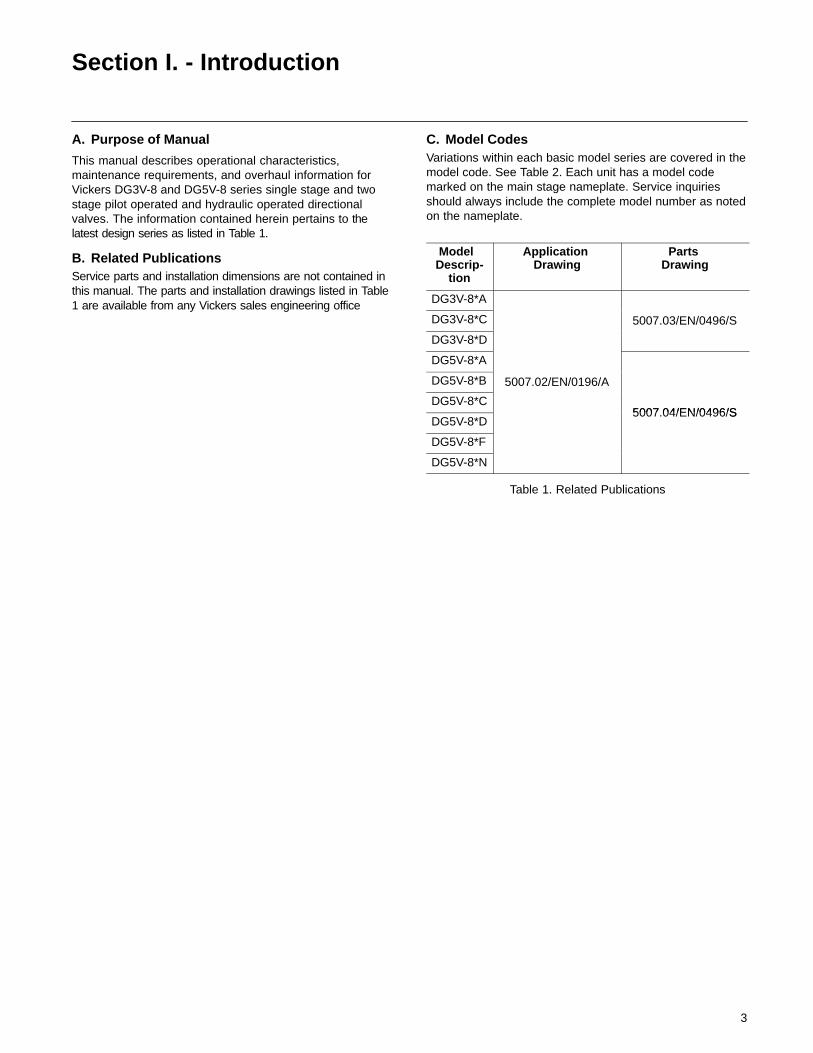
C. Model CodesVariations within each basic model series are covered in themodel code. See Table 2. Each unit has a model codemarked on the main stage nameplate. Service inquiriesshould always include the complete model number as notedon the nameplate.
Model Descrip-
tion
Application Drawing
Parts Drawing
DG3V-8*A
DG3V-8*C 5007.03/EN/0496/S
DG3V-8*D
DG5V-8*A
DG5V-8*B 5007.02/EN/0196/A
DG5V-8*C5007 04/EN/0496/S
DG5V-8*D5007.04/EN/0496/S
DG5V-8*F
DG5V-8*N
Table 1. Related Publications
4
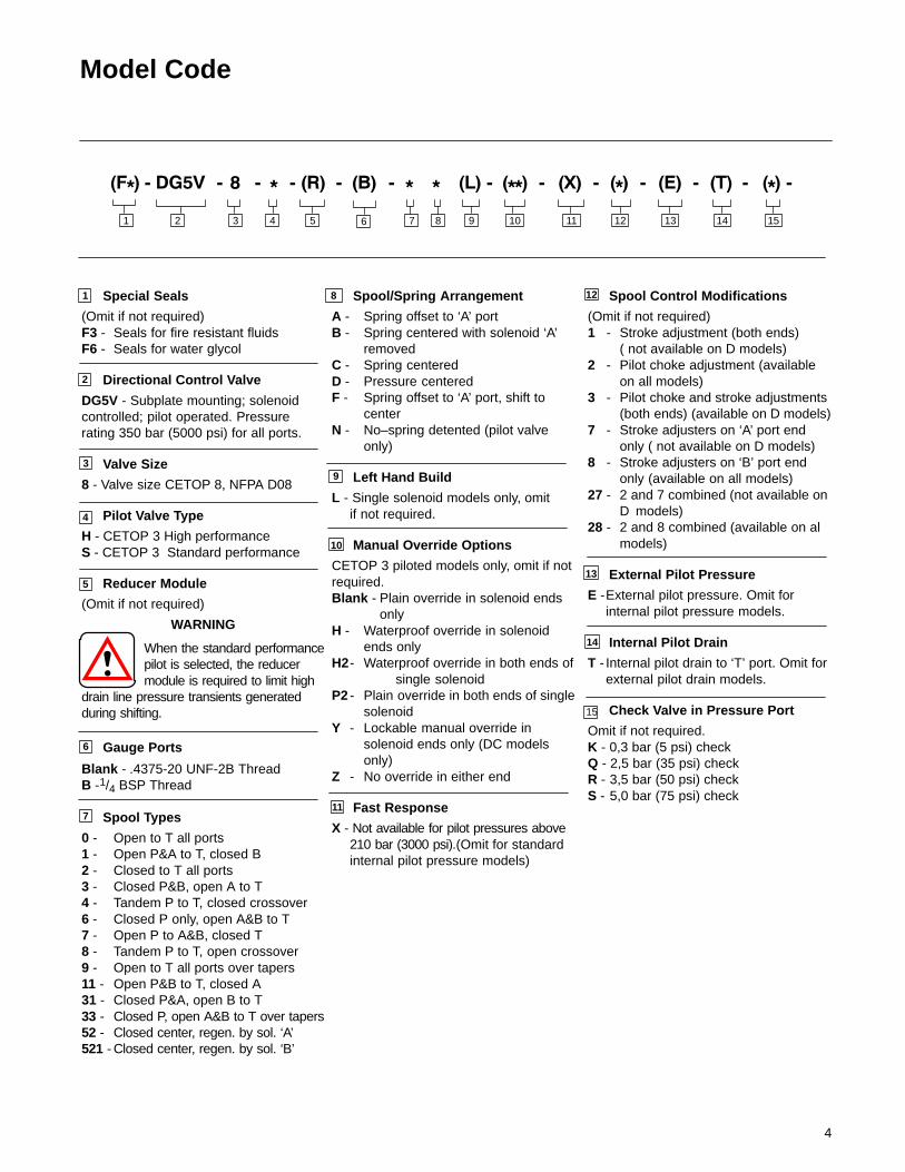
Model Code
Special Seals
(Omit if not required)F3 - Seals for fire resistant fluidsF6 - Seals for water glycol
Directional Control Valve
DG5V - Subplate mounting; solenoidcontrolled; pilot operated. Pressurerating 350 bar (5000 psi) for all ports.
Valve Size
8 - Valve size CETOP 8, NFPA D08
Pilot Valve Type
H - CETOP 3 High performanceS - CETOP 3 Standard performance
Reducer Module
(Omit if not required)
WARNING
When the standard performancepilot is selected, the reducermodule is required to limit high
drain line pressure transients generatedduring shifting.
Gauge Ports
Blank - .4375-20 UNF-2B ThreadB -1/4 BSP Thread
Spool Types
0 - Open to T all ports1 - Open P&A to T, closed B2 - Closed to T all ports3 - Closed P&B, open A to T4 - Tandem P to T, closed crossover6 - Closed P only, open A&B to T7 - Open P to A&B, closed T8 - Tandem P to T, open crossover9 - Open to T all ports over tapers11 - Open P&B to T, closed A31 - Closed P&A, open B to T33 - Closed P, open A&B to T over tapers52 - Closed center, regen. by sol. ‘A’521 - Closed center, regen. by sol. ‘B’
Spool Control Modifications
(Omit if not required)1 - Stroke adjustment (both ends)
( not available on D models)2 - Pilot choke adjustment (available
on all models)3 - Pilot choke and stroke adjustments
(both ends) (available on D models)7 - Stroke adjusters on ‘A’ port end
only ( not available on D models)8 - Stroke adjusters on ‘B’ port end
only (available on all models)27 - 2 and 7 combined (not available on
D models)28 - 2 and 8 combined (available on al
models)
External Pilot Pressure
E -External pilot pressure. Omit for internal pilot pressure models.
Internal Pilot Drain
T - Internal pilot drain to ‘T’ port. Omit for external pilot drain models.
Check Valve in Pressure Port
Omit if not required.K - 0,3 bar (5 psi) checkQ - 2,5 bar (35 psi) checkR - 3,5 bar (50 psi) checkS - 5,0 bar (75 psi) check
1
2
3
4
5
8
7
6
Spool/Spring Arrangement
A - Spring offset to ‘A’ portB - Spring centered with solenoid ‘A’
removedC - Spring centeredD - Pressure centeredF - Spring offset to ‘A’ port, shift to
centerN - No–spring detented (pilot valve
only)
Left Hand Build
L - Single solenoid models only, omit if not required.
Manual Override Options
CETOP 3 piloted models only, omit if notrequired.Blank - Plain override in solenoid ends
onlyH - Waterproof override in solenoid
ends only H2- Waterproof override in both ends of
single solenoidP2 - Plain override in both ends of single
solenoidY - Lockable manual override in
solenoid ends only (DC models only)
Z - No override in either end
Fast Response
X - Not available for pilot pressures above 210 bar (3000 psi).(Omit for standard internal pilot pressure models)
9
10
11
12
13
14
2 3 4 75 81 10 11 12 13 14 1596
15
5
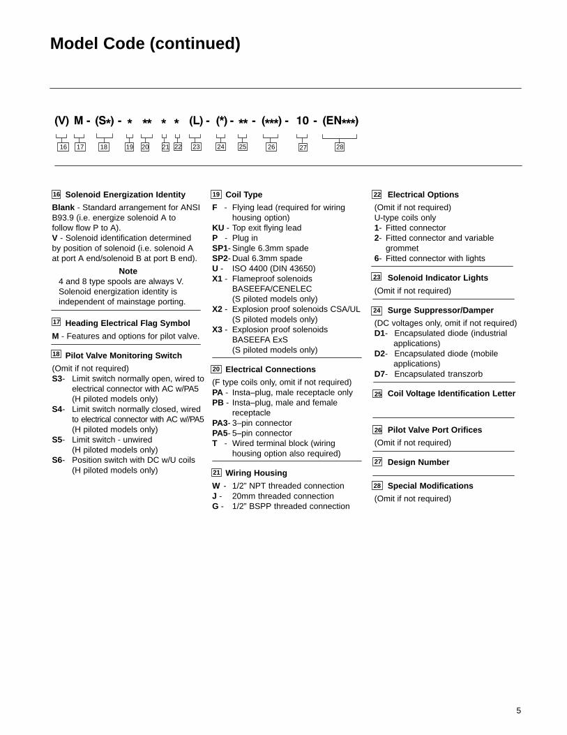
Model Code (continued)
20
18
21
17
28
16 Solenoid Energization Identity
Blank - Standard arrangement for ANSIB93.9 (i.e. energize solenoid A tofollow flow P to A).V - Solenoid identification determinedby position of solenoid (i.e. solenoid Aat port A end/solenoid B at port B end).
Note4 and 8 type spools are always V.Solenoid energization identity isindependent of mainstage porting.
Heading Electrical Flag Symbol
M - Features and options for pilot valve.
Pilot Valve Monitoring Switch
(Omit if not required)S3- Limit switch normally open, wired to
electrical connector with AC w/PA5(H piloted models only)
S4- Limit switch normally closed, wired to electrical connector with AC w//PA5(H piloted models only)
S5- Limit switch - unwired(H piloted models only)
S6- Position switch with DC w/U coils(H piloted models only)
Coil Type
F - Flying lead (required for wiring housing option)
KU - Top exit flying leadP - Plug in SP1- Single 6.3mm spadeSP2- Dual 6.3mm spadeU - ISO 4400 (DIN 43650)X1 - Flameproof solenoids
BASEEFA/CENELEC(S piloted models only)
X2 - Explosion proof solenoids CSA/UL (S piloted models only)
X3 - Explosion proof solenoids BASEEFA ExS (S piloted models only)
Electrical Connections
(F type coils only, omit if not required)PA - Insta–plug, male receptacle onlyPB - Insta–plug, male and female
receptaclePA3- 3–pin connectorPA5- 5–pin connectorT - Wired terminal block (wiring
housing option also required)
Wiring Housing
W - 1/2” NPT threaded connectionJ - 20mm threaded connectionG - 1/2” BSPP threaded connection
Electrical Options
(Omit if not required)U-type coils only1- Fitted connector2- Fitted connector and variable
grommet6- Fitted connector with lights
Solenoid Indicator Lights
(Omit if not required)
Surge Suppressor/Damper
(DC voltages only, omit if not required)D1- Encapsulated diode (industrial applications)D2- Encapsulated diode (mobile applications)D7- Encapsulated transzorb
Coil Voltage Identification Letter
Pilot Valve Port Orifices
(Omit if not required)
Design Number
Special Modifications
(Omit if not required)
22
25
26
23
24
27
19
16 17 18 19 2620 21 22 23 24 25 27 28
6
Section II. - Description
A. GeneralDirectional valves are devices used to change the flowdirection of fluid within a hydraulic circuit. A valve isdesigned to control the direction of movement of a workcylinder or the direction of rotation of a fluid motor.
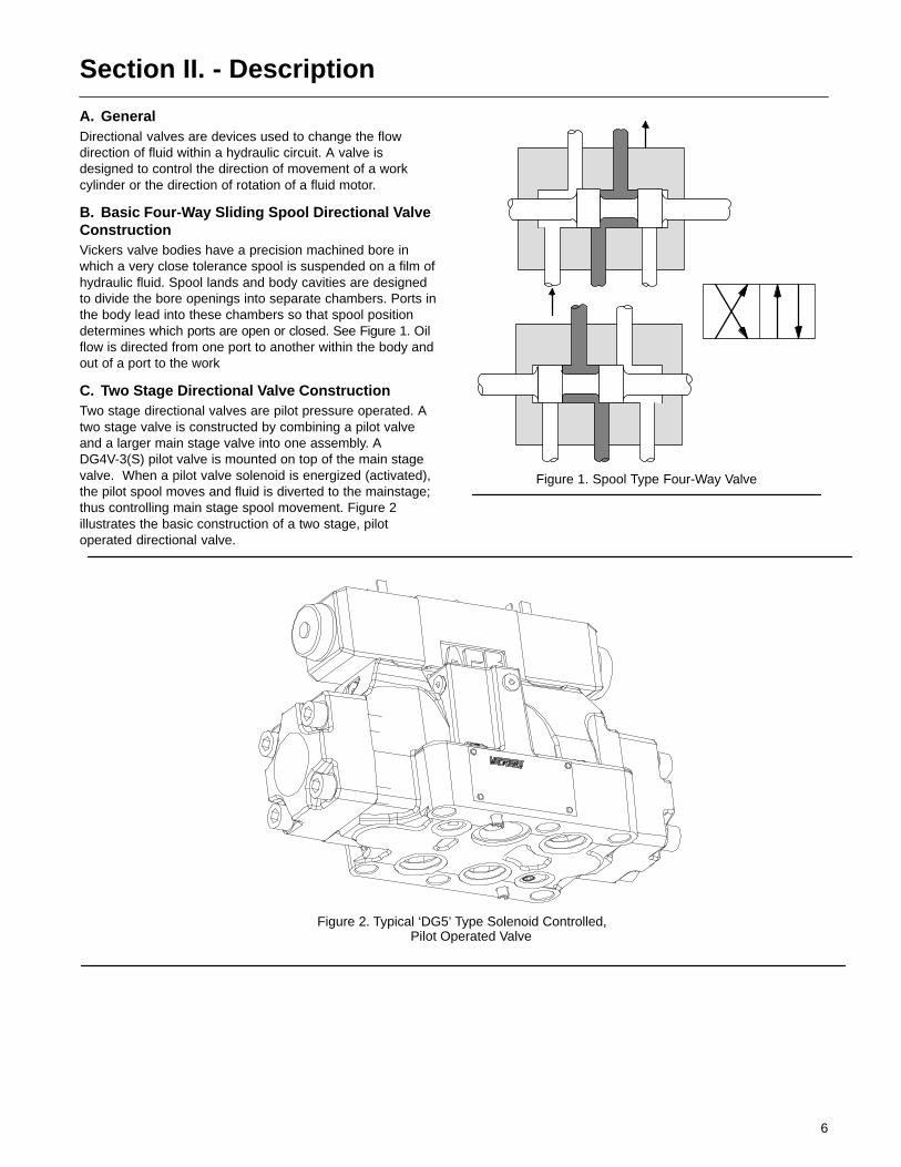
B. Basic Four-Way Sliding Spool Directional ValveConstructionVickers valve bodies have a precision machined bore inwhich a very close tolerance spool is suspended on a film ofhydraulic fluid. Spool lands and body cavities are designedto divide the bore openings into separate chambers. Ports inthe body lead into these chambers so that spool positiondetermines which ports are open or closed. See Figure 1. Oilflow is directed from one port to another within the body andout of a port to the work
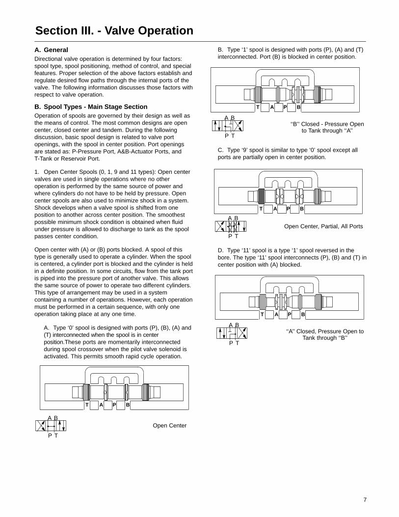
C. Two Stage Directional Valve ConstructionTwo stage directional valves are pilot pressure operated. Atwo stage valve is constructed by combining a pilot valveand a larger main stage valve into one assembly. ADG4V-3(S) pilot valve is mounted on top of the main stagevalve. When a pilot valve solenoid is energized (activated),the pilot spool moves and fluid is diverted to the mainstage;thus controlling main stage spool movement. Figure 2illustrates the basic construction of a two stage, pilotoperated directional valve.
Figure 1. Spool Type Four-Way Valve
Figure 2. Typical ‘DG5’ Type Solenoid Controlled, Pilot Operated Valve
7
Section III. - Valve Operation
A. GeneralDirectional valve operation is determined by four factors:spool type, spool positioning, method of control, and specialfeatures. Proper selection of the above factors establish andregulate desired flow paths through the internal ports of thevalve. The following information discusses those factors withrespect to valve operation.
B. Spool Types - Main Stage SectionOperation of spools are governed by their design as well asthe means of control. The most common designs are opencenter, closed center and tandem. During the followingdiscussion, basic spool design is related to valve portopenings, with the spool in center position. Port openingsare stated as: P-Pressure Port, A&B-Actuator Ports, andT-Tank or Reservoir Port.
1. Open Center Spools (0, 1, 9 and 11 types): Open centervalves are used in single operations where no otheroperation is performed by the same source of power andwhere cylinders do not have to be held by pressure. Opencenter spools are also used to minimize shock in a system.Shock develops when a valve spool is shifted from oneposition to another across center position. The smoothestpossible minimum shock condition is obtained when fluidunder pressure is allowed to discharge to tank as the spoolpasses center condition.
Open center with (A) or (B) ports blocked. A spool of thistype is generally used to operate a cylinder. When the spoolis centered, a cylinder port is blocked and the cylinder is heldin a definite position. In some circuits, flow from the tank portis piped into the pressure port of another valve. This allowsthe same source of power to operate two different cylinders.This type of arrangement may be used in a systemcontaining a number of operations. However, each operationmust be performed in a certain sequence, with only oneoperation taking place at any one time.
A. Type ‘0’ spool is designed with ports (P), (B), (A) and(T) interconnected when the spool is in centerposition.These ports are momentarily interconnectedduring spool crossover when the pilot valve solenoid isactivated. This permits smooth rapid cycle operation.
T A P B
Open CenterA B
P T
B. Type ‘1’ spool is designed with ports (P), (A) and (T)interconnected. Port (B) is blocked in center position.
‘‘B’’ Closed - Pressure Opento Tank through ‘‘A’’
T A P B
A B
P T
C. Type ‘9’ spool is similar to type ‘0’ spool except allports are partially open in center position.
Open Center, Partial, All Ports
T A P B
A B
P T
)( )()( )(
D. Type ‘11’ spool is a type ‘1’ spool reversed in thebore. The type ‘11’ spool interconnects (P), (B) and (T) incenter position with (A) blocked.
‘‘A’’ Closed, Pressure Open toTank through ‘‘B’’
T A P B
A B
P T

8
2. Closed Center Spools (2, 3, 6, 31, 33, 52 and 521 types):Closed center spools are used where two or more operationsare performed by a single pump or an accumulator. Closedcenter valves prevent the loss of fluid from the pump oraccumulator when the spool crosses center.
A. Type ‘2’ spool blocks ports (P), (A), (B) and (T) fromone another in the center position. The ports aremomentarily blocked during spool crossover.
Closed Center - All Ports Closed
T A P B
A B
P T
B. Type ‘3’ spool is designed with ports (A) and (T)interconnected and ports (P) and (B) blocked in thecenter position.
Pressure and ‘‘B’’ Closed - ‘‘A’’ Open to Tank
T A P B
A B
P T
C. Type ‘6’ spool is interconnected at ports (A), (B) and(T). Port (P) is blocked in the center position.
Pressure Closed - ‘‘A’’ & ‘‘B’’ Open to Tank
T A P B
A B
P T
D. Type ‘31’ spool is a type ‘3’ spool reversed in thebore. A type ‘31’ spool is interconnected at ports (B) and (T), but blocked at ports (P) and (A) in the center position.
Pressure and ‘‘A’’ Closed - ‘‘B’’ Open to Tank
T A P B
A B
P T
E. Type ‘33’ spool provides controlled leakage from port (A) and (B) to port (T). Port (P) is blocked in the centerposition.
Closed Center - Bleed ‘‘A’’ & ‘‘B’’
T A P B
A B
P T
)( )(
F. Type ‘52’ spool
Closed Center, Regen. by Solenoid ‘A’
T A P B
A B
P T
G. Type ‘521’ spool
Closed Center,Regen. by Solenoid ‘B’
T A P B
A B
P T
9
3. Tandem spools (4 and 8 types): Tandem spool valves areused in hydraulic circuits where two or more hydrauliccylinders or motors are controlled from a single source ofpower. The valve’s spool is designed so that in centerposition, all cylinder connections are blocked and fullpump delivery is connected to tank. The tank connectionof one valve may be connected to the pressureconnection of another valve and both valves operatedsimultaneously as long a the combined pressuresdeveloped by the two loads are within the capabilities ofthe power source.
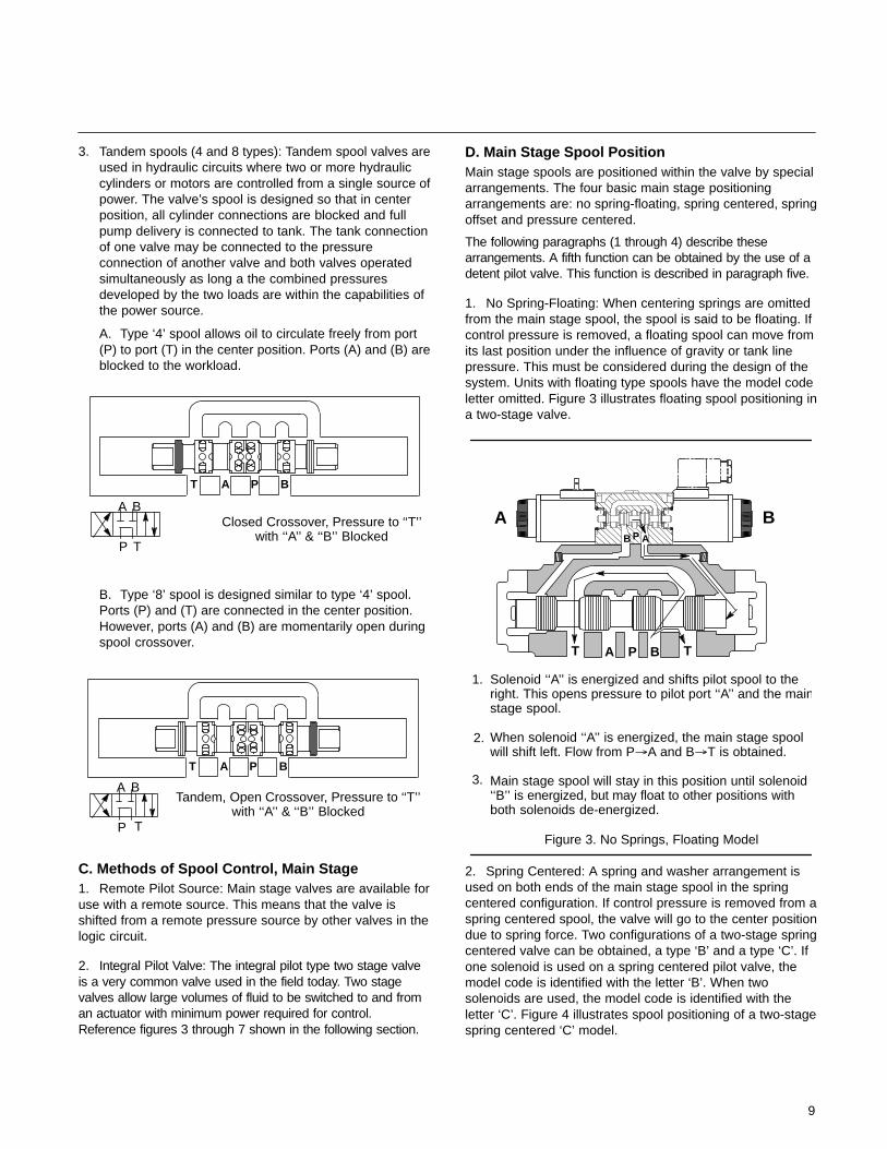
A. Type ‘4’ spool allows oil to circulate freely from port (P) to port (T) in the center position. Ports (A) and (B) areblocked to the workload.
Closed Crossover, Pressure to ‘‘T’’with ‘‘A’’ & ‘‘B’’ Blocked
T A P B
A B
P T
B. Type ‘8’ spool is designed similar to type ‘4’ spool. Ports (P) and (T) are connected in the center position. However, ports (A) and (B) are momentarily open during spool crossover.
Tandem, Open Crossover, Pressure to ‘‘T’’with ‘‘A’’ & ‘‘B’’ Blocked
T A P B
A B
P T
C. Methods of Spool Control, Main Stage1. Remote Pilot Source: Main stage valves are available foruse with a remote source. This means that the valve isshifted from a remote pressure source by other valves in thelogic circuit.
2. Integral Pilot Valve: The integral pilot type two stage valveis a very common valve used in the field today. Two stagevalves allow large volumes of fluid to be switched to and froman actuator with minimum power required for control.Reference figures 3 through 7 shown in the following section.
D. Main Stage Spool PositionMain stage spools are positioned within the valve by specialarrangements. The four basic main stage positioningarrangements are: no spring-floating, spring centered, springoffset and pressure centered.
The following paragraphs (1 through 4) describe thesearrangements. A fifth function can be obtained by the use of adetent pilot valve. This function is described in paragraph five.
1. No Spring-Floating: When centering springs are omittedfrom the main stage spool, the spool is said to be floating. Ifcontrol pressure is removed, a floating spool can move fromits last position under the influence of gravity or tank linepressure. This must be considered during the design of thesystem. Units with floating type spools have the model codeletter omitted. Figure 3 illustrates floating spool positioning ina two-stage valve.
Figure 3. No Springs, Floating Model
Solenoid ‘‘A’’ is energized and shifts pilot spool to theright. This opens pressure to pilot port ‘‘A’’ and the mainstage spool.
When solenoid ‘‘A’’ is energized, the main stage spoolwill shift left. Flow from P�A and B�T is obtained.
Main stage spool will stay in this position until solenoid‘‘B’’ is energized, but may float to other positions withboth solenoids de-energized.
1.
2.
3.
A B
T A P B T
PB A
2. Spring Centered: A spring and washer arrangement isused on both ends of the main stage spool in the springcentered configuration. If control pressure is removed from aspring centered spool, the valve will go to the center positiondue to spring force. Two configurations of a two-stage springcentered valve can be obtained, a type ‘B’ and a type ‘C’. Ifone solenoid is used on a spring centered pilot valve, themodel code is identified with the letter ‘B’. When twosolenoids are used, the model code is identified with theletter ‘C’. Figure 4 illustrates spool positioning of a two-stagespring centered ‘C’ model.
10
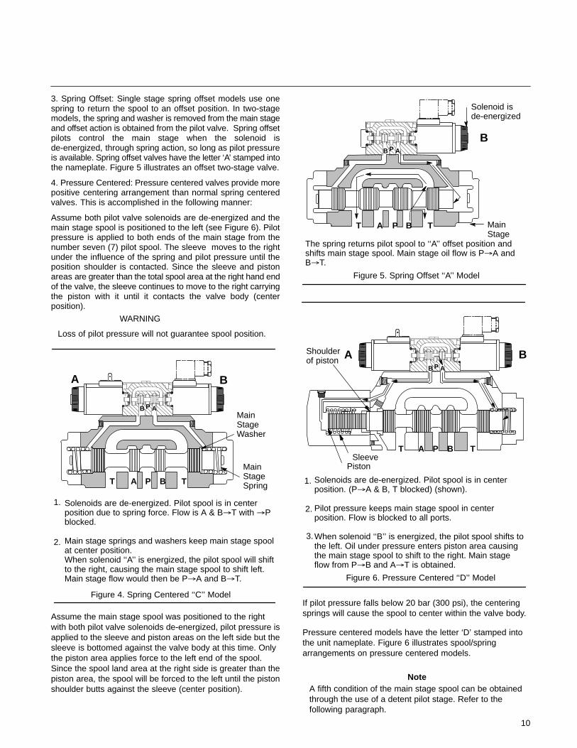
3. Spring Offset: Single stage spring offset models use onespring to return the spool to an offset position. In two-stagemodels, the spring and washer is removed from the main stageand offset action is obtained from the pilot valve. Spring offsetpilots control the main stage when the solenoid isde-energized, through spring action, so long as pilot pressureis available. Spring offset valves have the letter ‘A’ stamped intothe nameplate. Figure 5 illustrates an offset two-stage valve.
4. Pressure Centered: Pressure centered valves provide morepositive centering arrangement than normal spring centeredvalves. This is accomplished in the following manner:
Assume both pilot valve solenoids are de-energized and themain stage spool is positioned to the left (see Figure 6). Pilotpressure is applied to both ends of the main stage from thenumber seven (7) pilot spool. The sleeve moves to the rightunder the influence of the spring and pilot pressure until theposition shoulder is contacted. Since the sleeve and pistonareas are greater than the total spool area at the right hand endof the valve, the sleeve continues to move to the right carryingthe piston with it until it contacts the valve body (centerposition).
WARNING
Loss of pilot pressure will not guarantee spool position.
Figure 4. Spring Centered ‘‘C’’ Model
Solenoids are de-energized. Pilot spool is in centerposition due to spring force. Flow is A & B�T with �Pblocked.
Main stage springs and washers keep main stage spoolat center position. When solenoid ‘‘A’’ is energized, the pilot spool will shiftto the right, causing the main stage spool to shift left.Main stage flow would then be P�A and B�T.
1.
2.
MainStageSpring
MainStageWasher
T A P B T
PB A
A B
Assume the main stage spool was positioned to the rightwith both pilot valve solenoids de-energized, pilot pressure isapplied to the sleeve and piston areas on the left side but thesleeve is bottomed against the valve body at this time. Onlythe piston area applies force to the left end of the spool.Since the spool land area at the right side is greater than thepiston area, the spool will be forced to the left until the pistonshoulder butts against the sleeve (center position).
Figure 5. Spring Offset ‘‘A’’ Model
The spring returns pilot spool to ‘‘A’’ offset position andshifts main stage spool. Main stage oil flow is P�A andB�T.
Solenoid isde-energized
Main Stage
B
T A P B T
PB A
Figure 6. Pressure Centered ‘‘D’’ Model
Solenoids are de-energized. Pilot spool is in centerposition. (P�A & B, T blocked) (shown).
Pilot pressure keeps main stage spool in centerposition. Flow is blocked to all ports.
When solenoid ‘‘B’’ is energized, the pilot spool shifts tothe left. Oil under pressure enters piston area causingthe main stage spool to shift to the right. Main stageflow from P�B and A�T is obtained.
1.
2.
3.
Shoulder of piston
PistonSleeve
A BPT T
A BPB A
If pilot pressure falls below 20 bar (300 psi), the centeringsprings will cause the spool to center within the valve body.
Pressure centered models have the letter ‘D’ stamped intothe unit nameplate. Figure 6 illustrates spool/springarrangements on pressure centered models.
NoteA fifth condition of the main stage spool can be obtainedthrough the use of a detent pilot stage. Refer to thefollowing paragraph.
11
5. Detent Valve Operation: Detent valve operation can beachieved by installing a detent into the pilot valve. A detent isassembled on one or both ends of the pilot spool depending onthe type of pilot valve used. When a pilot valve solenoid isde-energized, the detent holds the pilot spool in the last positionattained and the main stage spool remains in its last position.
�
WARNINGIf pilot pressure fails or falls below the minimumrequirement of 5 bar (75 psi), the main stage spool will shiftto center position even though the pilot valve remains in thelast detent position. For this reason, flow conditions incenter or neutral position must be selected with care.
Detent models are indicated by the letter ‘N’ stamped intothe unit nameplate. Figure 7 illustrates the spool/springarrangement on detent models.
Figure 7. Detented ‘‘N’’ Model
Solenoid ‘‘A’’ is energized and shifts pilot spool to the right.
Which causes main stage spool to shift left. Oil flowfrom P�A and B�T is obtained.
Main stage spool remains in position attained due to pilotvalve detent until solenoid ‘‘B’’ is energized. (Note: If pilotpressure fails, the main stage will shift to center position.
1.
2.
3.
Detent
Main Stage
A B
A BP T
PAB
T
PilotSolenoid
E. Optional Features (Main Stage)Control of the mainstage spool travel can be modified withcertain optional features. The most common features arediscussed in the following paragraphs.
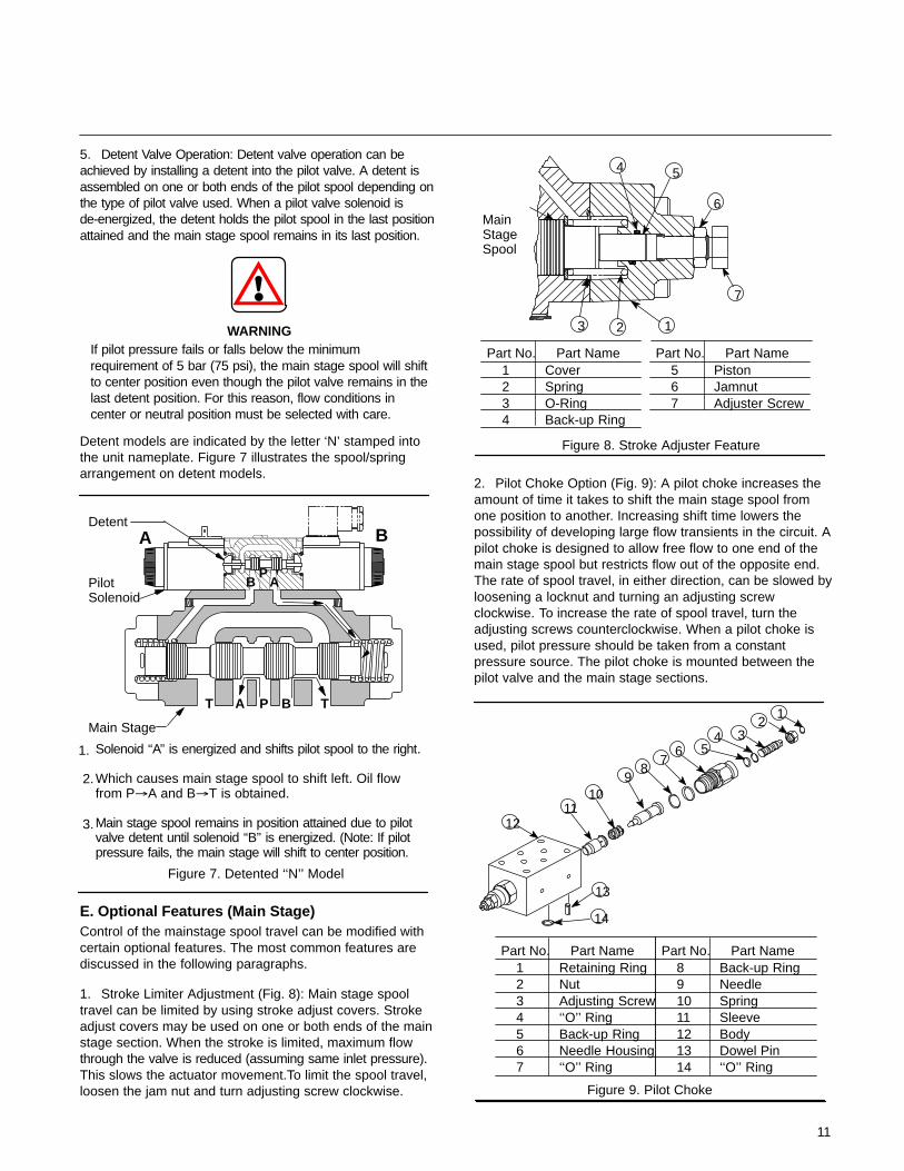
1. Stroke Limiter Adjustment (Fig. 8): Main stage spooltravel can be limited by using stroke adjust covers. Strokeadjust covers may be used on one or both ends of the mainstage section. When the stroke is limited, maximum flowthrough the valve is reduced (assuming same inlet pressure).This slows the actuator movement.To limit the spool travel,loosen the jam nut and turn adjusting screw clockwise.
Figure 8. Stroke Adjuster Feature
2
7
5
13
4
6MainStageSpool
Part No. Part Name1234
CoverSpringO-RingBack-up Ring
Part No. Part Name567
PistonJamnutAdjuster Screw
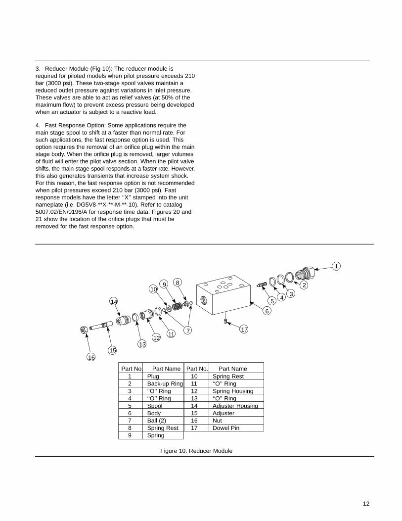
2. Pilot Choke Option (Fig. 9): A pilot choke increases theamount of time it takes to shift the main stage spool fromone position to another. Increasing shift time lowers thepossibility of developing large flow transients in the circuit. Apilot choke is designed to allow free flow to one end of themain stage spool but restricts flow out of the opposite end.The rate of spool travel, in either direction, can be slowed byloosening a locknut and turning an adjusting screwclockwise. To increase the rate of spool travel, turn theadjusting screws counterclockwise. When a pilot choke isused, pilot pressure should be taken from a constantpressure source. The pilot choke is mounted between thepilot valve and the main stage sections.
Figure 9. Pilot Choke
79
5
1
6
12
13
4
14
23
8
1110
Part No. Part Name1234567
Retaining RingNutAdjusting Screw‘‘O’’ RingBack-up RingNeedle Housing‘‘O’’ Ring
Part No. Part Name891011121314
Back-up RingNeedleSpringSleeveBodyDowel Pin‘‘O’’ Ring
12
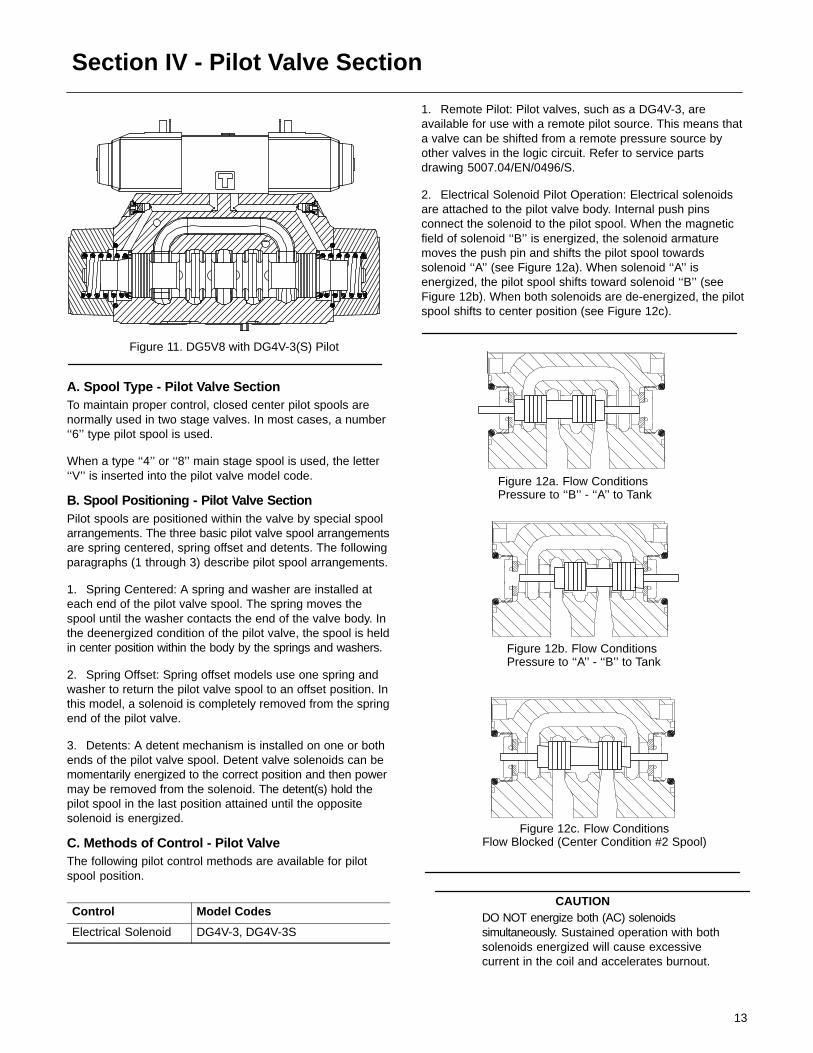
3. Reducer Module (Fig 10): The reducer module isrequired for piloted models when pilot pressure exceeds 210bar (3000 psi). These two-stage spool valves maintain areduced outlet pressure against variations in inlet pressure.These valves are able to act as relief valves (at 50% of themaximum flow) to prevent excess pressure being developedwhen an actuator is subject to a reactive load.
4. Fast Response Option: Some applications require themain stage spool to shift at a faster than normal rate. Forsuch applications, the fast response option is used. Thisoption requires the removal of an orifice plug within the mainstage body. When the orifice plug is removed, larger volumesof fluid will enter the pilot valve section. When the pilot valveshifts, the main stage spool responds at a faster rate. However,this also generates transients that increase system shock.For this reason, the fast response option is not recommendedwhen pilot pressures exceed 210 bar (3000 psi). Fastresponse models have the letter ‘‘X’’ stamped into the unitnameplate (i.e. DG5V8-**X-**-M-**-10). Refer to catalog5007.02/EN/0196/A for response time data. Figures 20 and21 show the location of the orifice plugs that must beremoved for the fast response option.
Figure 10. Reducer Module
1
2
54
3
7
6
89
11
10
1213
14
Part No. Part Name123456789
PlugBack-up Ring‘‘O’’ Ring‘‘O’’ RingSpoolBodyBall (2)Spring RestSpring
Part No. Part Name1011121314151617
Spring Rest‘‘O’’ RingSpring Housing‘‘O’’ RingAdjuster HousingAdjusterNutDowel Pin
1615
17
13
Section IV - Pilot Valve Section
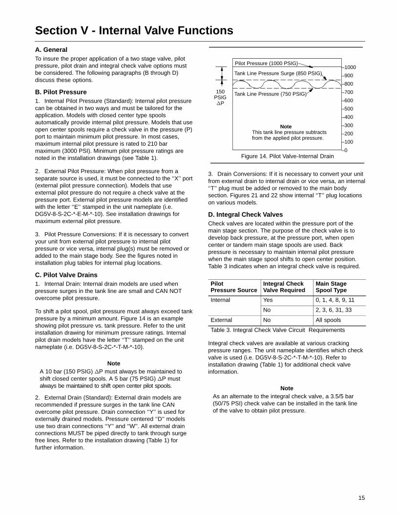
Figure 11. DG5V8 with DG4V-3(S) Pilot
A. Spool Type - Pilot Valve SectionTo maintain proper control, closed center pilot spools arenormally used in two stage valves. In most cases, a number‘‘6’’ type pilot spool is used.
When a type ‘‘4’’ or ‘‘8’’ main stage spool is used, the letter‘‘V’’ is inserted into the pilot valve model code.
B. Spool Positioning - Pilot Valve SectionPilot spools are positioned within the valve by special spoolarrangements. The three basic pilot valve spool arrangementsare spring centered, spring offset and detents. The followingparagraphs (1 through 3) describe pilot spool arrangements.
1. Spring Centered: A spring and washer are installed ateach end of the pilot valve spool. The spring moves thespool until the washer contacts the end of the valve body. Inthe deenergized condition of the pilot valve, the spool is heldin center position within the body by the springs and washers.
2. Spring Offset: Spring offset models use one spring andwasher to return the pilot valve spool to an offset position. Inthis model, a solenoid is completely removed from the springend of the pilot valve.
3. Detents: A detent mechanism is installed on one or bothends of the pilot valve spool. Detent valve solenoids can bemomentarily energized to the correct position and then powermay be removed from the solenoid. The detent(s) hold thepilot spool in the last position attained until the oppositesolenoid is energized.
C. Methods of Control - Pilot ValveThe following pilot control methods are available for pilotspool position.
Control Model Codes
Electrical Solenoid DG4V-3, DG4V-3S
1. Remote Pilot: Pilot valves, such as a DG4V-3, areavailable for use with a remote pilot source. This means thata valve can be shifted from a remote pressure source byother valves in the logic circuit. Refer to service partsdrawing 5007.04/EN/0496/S.
2. Electrical Solenoid Pilot Operation: Electrical solenoidsare attached to the pilot valve body. Internal push pinsconnect the solenoid to the pilot spool. When the magneticfield of solenoid ‘‘B’’ is energized, the solenoid armaturemoves the push pin and shifts the pilot spool towardssolenoid ‘‘A’’ (see Figure 12a). When solenoid ‘‘A’’ isenergized, the pilot spool shifts toward solenoid ‘‘B’’ (seeFigure 12b). When both solenoids are de-energized, the pilotspool shifts to center position (see Figure 12c).
Figure 12a. Flow ConditionsPressure to ‘‘B’’ - ‘‘A’’ to Tank
Figure 12b. Flow ConditionsPressure to ‘‘A’’ - ‘‘B’’ to Tank
Figure 12c. Flow ConditionsFlow Blocked (Center Condition #2 Spool)
CAUTIONDO NOT energize both (AC) solenoidssimultaneously. Sustained operation with bothsolenoids energized will cause excessivecurrent in the coil and accelerates burnout.

14
A. Electrical Solenoid Types Available: Two basic typesof electrical solenoids exist:Standard and high performance.The unit nameplate identifies the type of solenoid beingused. See the model code in Table 2.
B. Electrical Solenoid Voltage Requirement: Electricalsolenoids are available in various AC and DC voltageranges. The standard voltage and frequency range is 115VAC, 60 Hz. Refer to parts and service drawings for units withnon-standard voltage ranges.Ten (-10) design units use anidentification letter for the coil voltage and frequency.
C. Electrical Solenoid Ground Connections and WiringHousing: An electrical wiring housing with a 1/2” NPTFthread connection is available on DG4V-3 pilot valves. Wiregrounding screws are provided for convenience.
D. Manual Override: Each solenoid has a manualoverride plunger to shift the pilot spool. This feature allows atechnician to shift the pilot spool when electricity is notavailable. Refer to Figure 13. To operate the manual overridefeature, obtain a small rod and push in on the plunger.
5. Accessories for Electrical Type Solenoids: The modelcode (Table 2) indicates the type of accessories used ondirectional valves. Obtain a parts and service drawing foryour particular model (see Table 1). Most accessoriespertain to the pilot section. The most common types ofaccessories are discussed in the following paragraphs (Athrough F).
A. Hazardous Location Solenoids: This type of is usedat locations where added protection from electrical shortagefailure is mandatory, the solenoid housing is designed tocompletely enclose all wiring connections to the valve.Hazardous location valves are approved Class 1, Group D orClass 2, Group E-F-G, for 1various voltages.
B. Monitor (Limit) Switch Feature: The monitor switchfeature can be incorporate into a basic spring offsetdirectional valve. The switch monitors valve spool positionand an be wired into control circuits. This permits electricalinterlocking of various hydraulic controlled motions withoutresorting to external mechanical arrangements. The monitorswitch is a single pole, double throw contact arrangementwith -normally closed and - normally open connections.Switch ratings are noted on installation drawing (Table 1).The monitor switch housing does not provide a manualplunger for operation of the switch or valve.
C. Insta-Plug Connectors: Pilot valves can be suppliedwith electrical connectors called insta-plugs. Theseconnectors allow quick disconnect of electrical power fromthe valve. The following data pertains to the insta-plug feature:
PA- A prefix of PA in the model code indicates the male plug section of the insta-plug feature is included on the valve.
PB- A prefix of PB in the model code indicates both the male plug and female receptacle are included with the valve. the insta-plug feature is available on the DG4V-3(S) directional valves.
Wiring NoteConnect white wires to ‘‘A’’ solenoid and black wires tothe ‘‘B’’ solenoid. Refer to parts drawing (Table 1) foradditional data.
D. Brad Harrison Connectors: Brad Harrison connectorsthread into the 1/2” NPTF opening in the wiring housing of aDG4V-3(S) directional valve.
PA3- A prefix of PA3 in the model code indicates the three pin male connector is included with the valve.
PA5- A prefix of PA5 in the model code indicates the five pin male connector is included with the valve.
Female Brad Harrison connectors are not available fromVickers and must be supplied by the customer.
E. Solenoid Indicator Lights: Solenoid indicator lights areavailable for installation on the DG4V-3(S) series directionalvalves. Indicator lights are connected across the solenoidsand will light when voltage is present at the solenoid. Thisgives an indication to the technician which solenoid isenergized and aids in troubleshooting a system. Refer to theappropriate parts drawing for additional information.
Figure 13. Typical DG4V-3(S)-C-FW-60
Terminal Box
FlyingLead Coil
ManualOverride Plunger
Wet Armature (Standard)Push Pin
Core Tube
SolenoidCoil
Pilot SpoolBody
15
Section V - Internal Valve Functions
A. GeneralTo insure the proper application of a two stage valve, pilotpressure, pilot drain and integral check valve options mustbe considered. The following paragraphs (B through D)discuss these options.
B. Pilot Pressure1. Internal Pilot Pressure (Standard): Internal pilot pressurecan be obtained in two ways and must be tailored for theapplication. Models with closed center type spoolsautomatically provide internal pilot pressure. Models that useopen center spools require a check valve in the pressure (P)port to maintain minimum pilot pressure. In most cases,maximum internal pilot pressure is rated to 210 barmaximum (3000 PSI). Minimum pilot pressure ratings arenoted in the installation drawings (see Table 1).
2. External Pilot Pressure: When pilot pressure from aseparate source is used, it must be connected to the ‘‘X’’ port(external pilot pressure connection). Models that useexternal pilot pressure do not require a check valve at thepressure port. External pilot pressure models are identifiedwith the letter ‘‘E’’ stamped in the unit nameplate (i.e.DG5V-8-S-2C-*-E-M-*-10). See installation drawings formaximum external pilot pressure.
3. Pilot Pressure Conversions: If it is necessary to convertyour unit from external pilot pressure to internal pilotpressure or vice versa, internal plug(s) must be removed oradded to the main stage body. See the figures noted ininstallation plug tables for internal plug locations.
C. Pilot Valve Drains1. Internal Drain: Internal drain models are used whenpressure surges in the tank line are small and CAN NOTovercome pilot pressure.
To shift a pilot spool, pilot pressure must always exceed tankpressure by a minimum amount. Figure 14 is an exampleshowing pilot pressure vs. tank pressure. Refer to the unitinstallation drawing for minimum pressure ratings. Internalpilot drain models have the letter ‘‘T’’ stamped on the unitnameplate (i.e. DG5V-8-S-2C-*-T-M-*-10).
NoteA 10 bar (150 PSIG) �P must always be maintained toshift closed center spools. A 5 bar (75 PSIG) �P mustalways be maintained to shift open center pilot spools.
2. External Drain (Standard): External drain models arerecommended if pressure surges in the tank line CANovercome pilot pressure. Drain connection ‘‘Y’’ is used forexternally drained models. Pressure centered ‘‘D’’ modelsuse two drain connections ‘‘Y’’ and ‘‘W’’. All external drainconnections MUST be piped directly to tank through surgefree lines. Refer to the installation drawing (Table 1) forfurther information.
Figure 14. Pilot Valve-Internal Drain
–1000
–900
–800
–700
–600
–500
–400
–300
–200
–100
–0
150PSIG�P
Pilot Pressure (1000 PSIG)
Tank Line Pressure Surge (850 PSIG)
Tank Line Pressure (750 PSIG)
NoteThis tank line pressure subtractsfrom the applied pilot pressure.
3. Drain Conversions: If it is necessary to convert your unitfrom external drain to internal drain or vice versa, an internal‘‘T’’ plug must be added or removed to the main bodysection. Figures 21 and 22 show internal ‘‘T’’ plug locationson various models.
D. Integral Check ValvesCheck valves are located within the pressure port of themain stage section. The purpose of the check valve is todevelop back pressure, at the pressure port, when opencenter or tandem main stage spools are used. Backpressure is necessary to maintain internal pilot pressurewhen the main stage spool shifts to open center position.Table 3 indicates when an integral check valve is required.
PilotPressure Source
Integral CheckValve Required
Main StageSpool Type
Internal Yes 0, 1, 4, 8, 9, 11
No 2, 3, 6, 31, 33
External No All spools
Table 3. Integral Check Valve Circuit Requirements
Integral check valves are available at various crackingpressure ranges. The unit nameplate identifies which checkvalve is used (i.e. DG5V-8-S-2C-*-T-M-*-10). Refer toinstallation drawing (Table 1) for additional check valveinformation.
NoteAs an alternate to the integral check valve, a 3.5/5 bar(50/75 PSI) check valve can be installed in the tank lineof the valve to obtain pilot pressure.

16
Section VI - InstallationA. Installation DrawingsThe installation drawings listed in Table 1 show installationdimensions, port locations and operating parameters.Manifold, subplate and bolt kit information is also included.
NoteDetent valves must be installed with the valve spool inthe horizontal position for good machine reliability. Themounting position of spring offset and spring centeredmodels is unrestricted.
NoteMake sure the ‘‘Y’’ drain port is piped directly to the tank.Back pressure cannot be tolerated at this valve port.
CAUTIONOn solenoid operated directional valves, ensurean electrical ground is connected to the valve.This prevents the possibility of a shock hazardif a coil develops a short circuit to the frame.
B. Fluids and SealsStandard seals (Nitrile) can be used with petroleum,water-glycols, and water-oil emulsion type fluids.
F1 seals (Butyl, EPR) must be used for alkylphosphate-ester base fluids and aircraft type fire-resistantfluids. F1 seals cannot be used with petroleum or phosphateester-hydrocarbon blends.
F3 seals (Viton�) can be used with all commonly usedindustrial hydraulic fluids. Viton� is compatible withpetroleum, water-base and synthetic fire-resistant fluids.
� Viton is a registered trademark of E.I. Dupont
F6 seals (Nitrile) can be used with petroleum, water-glycols,and water-oil emulsion type fluids.
The following table summarizes the compatibilities of themost common phosphate ester fluids.
Fluid Type F1 F3 F6
Skydrol Yes No No
Pydraul 10-E Yes No No
Pydraul 29-E-L-T, 50-E65-E, 115-E
Yes Yes Yes
Pydraul 230-C, 312-C,540-C
No Yes Yes
Fyrquel & Fyrlube Yes Yes Yes
Fyrtek No Yes Yes
Houghton Safe 1000 Series Yes Yes Yes
C. Piping and Tubing1. All pipes and tubing must be thoroughly cleaned beforeinstallation. Recommended cleaning methods aresandblasting, wire brushing and pickling.
2. To minimize flow resistance and the possibility of externalleakage, use only the necessary fittings and connectionsrequired for proper installation.
3. The number of bends in tubing should be kept to aminimum to prevent excessive turbulence and friction of fluidflow. Tubing must not be bent too sharply. The recommendedradius for tube ends is three times the inside diameter.
D. Hydraulic Fluid RecommendationsHydraulic fluid within the systems performs the dual functionof lubrication and transmission of power. To insure properlubrication, system life, and component reliability, fluidselection should be made carefully with the assistance of areputable supplier. Fluid selection should be acceptable foruse with all valves, motors and pumps within the system.
The fluid recommendations noted in the data sheet arebased on our experience in industry as a hydrauliccomponent supplier. Where special considerations indicate aneed to depart from these recommendations, see yourVickers sales representative.
E. CleanlinessTo ensure your hydraulic system is clean, perform thefollowing steps:
1. Clean (flush) the entire system to remove paint, metalchips, welding shot, etc.
2. Filter each oil change to prevent introduction ofcontaminants.
3. Provide continuous oil filtration to remove sludge,products of wear and corrosion generated during the lifeof the system.
4. Provide protection to all areas that can introduceairborne contaminants into the system.
5. Perform regular servicing procedures of filters, breathers,and reservoirs.
F. Overload ProtectionA relief valve must be installed in the system as close to thepump as possible. the relief valve limits pressure in thesystem to a prescribed maximum. The setting of the reliefvalve depends on the work requirements of the system.
17
Section VII - Service, Inspection & Maintenance
A. Service ToolsNo special tools are required to service this valve series.
B. InspectionPeriodic inspection of the fluid condition and tube or pipingconnections can save time consuming breakdown andunnecessary parts replacement. the following should bechecked regularly.
1. All hydraulic connections must be kept tight. A looseconnection in a pressure line will permit the fluid to leakout. If the fluid level becomes so low as to uncover theinlet pipe opening in the reservoir, extensive damage tothe system can result. Loose connections also permit airto be drawn into the system resulting in a noisy and/orerratic operation.
2. Clean fluid is the best insurance for long service life.Therefore, check the reservoir periodically for dirt andother contaminants. If the fluid becomes contaminated,flush the entire system and add new fluid.
3. Filter elements should also be checked periodically. Aclogged filter element will cause higher pressure dropswithin the system.
4. Air bubbles in the reservoir can ruin the valve and othercomponents. If bubbles are seen, locate the source ofthe air and seal the leak.
C. Adding Fluid to the SystemWhen hydraulic fluid is added to replenish the system, pour itthrough a fine wire screen (200 mesh or finer). Whenapplicable, pump the fluid through a 10 micron filter. DO
NOT use a cloth to strain the fluid or lint may enter thesystem.
D. AdjustmentsNo periodic adjustments are required other than normalsystem maintenance,
E. Replacement PartsReliable operation throughout the specified operating rangeis assured only if genuine Vickers parts are used.Sophisticated design processes and material are used in themanufacture of our parts. Substitutions may result in earlyfailure. Part numbers are shown in the parts and servicedrawings listed in Table 1.
F. Product LifeThe service life of this product is dependent uponenvironment, duty cycle, operating parameters and systemcleanliness. Since these parameters vary from application toapplication, the ultimate user must determine and establishthe periodic maintenance required to maximize life anddetect potential component failure.
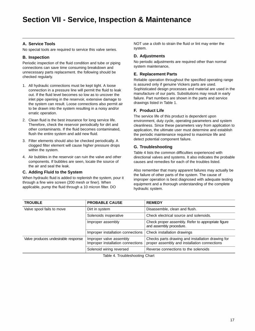
G. TroubleshootingTable 4 lists the common difficulties experienced withdirectional valves and systems. It also indicates the probablecauses and remedies for each of the troubles listed.
Also remember that many apparent failures may actually bethe failure of other parts of the system. The cause ofimproper operation is best diagnosed with adequate testingequipment and a thorough understanding of the completehydraulic system.
TROUBLE PROBABLE CAUSE REMEDY
Valve spool fails to move Dirt in system Disassemble, clean and flush.
Solenoids inoperative Check electrical source and solenoids.
Improper assembly Check proper assembly. Refer to appropriate figureand assembly procedure.
Improper installation connections Check installation drawings
Valve produces undesirable response Improper valve assemblyImproper installation connections
Checks parts drawing and installation drawing forproper assembly and installation connections
Solenoid wiring reversed Reverse connections to the solenoids
Table 4. Troubleshooting Chart
18
Section VIII - OverhaulWARNING
Before breaking a circuit connection, ensuresystem power is off and system pressure hasbeen relieved. Lower all vertical cylinders,discharge accumulators and block any load
whose movement could generate pressure. Plug all unitsand cap all lines to prevent entry of dirt into the unit orsystem.
A. Unit Removal
1. Thoroughly clean the exterior of the valve and the areaaround the valve to prevent contamination of the systemduring removal.
2. Remove the valve from its subplate or mounting pad asfollows:
A. If the valve is equipped with the insta-plug feature,loosen the two slotted screws and unplug the electricalwiring from the pilot section.
B. If the valve has an air operated section, turn off airsupply and disconnect the pressure lines from theconnection plate.
WARNINGIn the following step make sure electricalpower is off, then disconnect the solenoidwiring. Label each wire to provide assemblyinformation.
C. If the valve has standard electrically operatedsolenoids, remove the four nameplate screws on top ofthe pilot section. Move nameplate and gasket aside toexpose interior of the wire cavity. Disconnect solenoidwiring.
D. Loosen the six mounting screws that hold the mainstage section to the mounting pad. Be ready to catch thefluid retained inside the lines and valve.
E. Remove the valve from the mounting pad and set iton a clean work bench. Use a chain lift when necessary.
B. Disassembly (General)
The manual describes the disassembly sequence of a typicalDG5V8 two-stage directional valve. See Figures 17 and 18.Slight variations may be noted on your model depending onthe type of accessories and unit design. Figure 17 may beused for all models, except pressure centered ‘‘D’’ modelsregardless of the design. Refer to Section E and Figure 18for pressure centered ‘‘D’’ models. Figure 19 shows thedisassembly sequence of a DG4V-3(S)-*A(L)/B(L)-FJ/FW-60standard performance pilot valve.
C. Pilot Valve Crossover Plate Removal
1. Remove the four attaching screws (1) from the pilot valveor crossover plate (2). Remove the pilot valve from themain stage body (3).
NoteThe following section pertains to main stagedisassembly. If your unit does not require main stagedisassembly, omit the following section.
D. General Main Stage Disassembly(Refer to Figure 17)
WARNINGSpring in end cover is under tension. Slowlyremove end cover screws alternatively toavoid damge to equipment and injury topersonnel
NoteRepeat steps 1 and 2 for opposite side cover disassembly.
1. Loosen the four end cover screws (5) from end cover (6).Be ready to catch any oil trapped inside the unit. Removethe end cover and discard ‘‘O’’ ring (7).
NoteSpring (8) and washer (9) do not exist on spring offset‘‘A’’ or floating type models.
2. Remove spring (8) and washer (9) from the main stagespool (10).
3. Remove main stage spool (10) from body (3).
4 Turn the body (3) on its side and remove ‘‘O’’ rings (11and 12) and plugs (14) and (15) from mounting face.
5 Remove plugs (16) and (17) and ‘‘O’’ Rings (18) and (19)from body (3).
6. If necessary, remove rest pins (13) with vise grip pliers.
19
E. Pressure Centered Main Stage Disassembly (Refer to Figure 18)
1. Remove the four attaching screws (1) from the crossoverplate (2) and remove the crossover plate from the mainstage body (3).
NoteThe following section pertains to main stagedisassembly. If your unit does not require main stagedisassembly, omit the following section.
2. Loosen the four end cover screws (6) from end cover (7).Be ready to catch any oil trapped inside the unit. Removethe end cover, spring (10) and discard ‘‘O’’ ring (8).
3. Remove sleeve (11) and piston (12) from the main stagespool (9).
4. Remove main stage spool (9) from body (3).
NotePerform step 5 for opposite side cover disassembly. Notethat centering springs are different.
5. Loosen the four end cover screws (13) from end cover(14). Be ready to catch any oil trapped inside the unit.Remove the end cover, spring (15), centering washer(16) and ‘‘O’’ Ring (17).
6. Remove plug (18) and ‘‘O’’ Ring (19) from cover (7).
7. Turn the body (3) on its side and remove ‘‘O’’ rings (20,24, 25 and 26) from mounting face.
8. If necessary, remove rest pins (27) with vise grip pliers.
NoteThe following step pertains to integral check valvemodels only. DO NOT remove check valve parts unlessinspection or unit operation indicates a check valveproblem. If check valve removal is necessary, performstep 9.
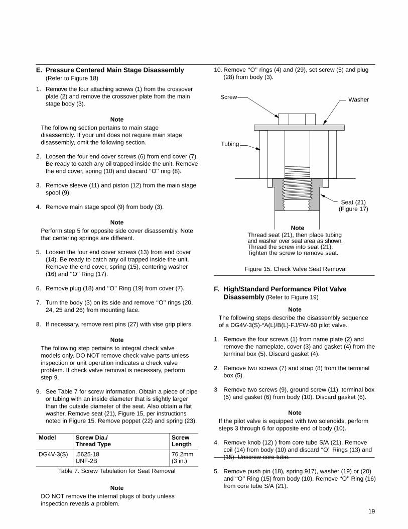
9. See Table 7 for screw information. Obtain a piece of pipeor tubing with an inside diameter that is slightly largerthan the outside diameter of the seat. Also obtain a flatwasher. Remove seat (21), Figure 15, per instructionsnoted in Figure 15. Remove poppet (22) and spring (23).
Model Screw Dia./Thread Type
ScrewLength
DG4V-3(S) .5625-18UNF-2B
76.2mm(3 in.)
Table 7. Screw Tabulation for Seat Removal
NoteDO NOT remove the internal plugs of body unlessinspection reveals a problem.
10. Remove ‘‘O’’ rings (4) and (29), set screw (5) and plug(28) from body (3).
Figure 15. Check Valve Seat Removal
NoteThread seat (21), then place tubingand washer over seat area as shown.Thread the screw into seat (21).Tighten the screw to remove seat.
Screw
Tubing
Washer
Seat (21)(Figure 17)
F. High/Standard Performance Pilot Valve Disassembly (Refer to Figure 19)
NoteThe following steps describe the disassembly sequenceof a DG4V-3(S)-*A(L)/B(L)-FJ/FW-60 pilot valve.
1. Remove the four screws (1) from name plate (2) andremove the nameplate, cover (3) and gasket (4) from theterminal box (5). Discard gasket (4).
2. Remove two screws (7) and strap (8) from the terminalbox (5).
3 Remove two screws (9), ground screw (11), terminal box(5) and gasket (6) from body (10). Discard gasket (6).
NoteIf the pilot valve is equipped with two solenoids, performsteps 3 through 6 for opposite end of body (10).
4. Remove knob (12) ) from core tube S/A (21). Removecoil (14) from body (10) and discard ‘‘O’’ Rings (13) and(15). Unscrew core tube.
5. Remove push pin (18), spring 917), washer (19) or (20)and ‘‘O’’ Ring (15) from body (10). Remove ‘‘O’’ Ring (16)from core tube S/A (21).
20
6. Remove pilot spool (22) from body (10).
7. Secure the body and remove plug (24) and ‘‘O’’ Ring (25)from body (10). Discard ‘‘O’’ Ring (25).
8 If necessary, remove rest pins (26) with vise grip pliers.
H. Cleaning
All parts must be thoroughly cleaned and kept clean duringinspection and assembly. Close tolerance of valve bodiesand spools make this requirement critical. Clean all partswith a commercial solvent that is compatible with systemfluid. Compressed air may be used to clean valve, but itmust be filtered to remove water and contamination. Cleancompressed air is particularly useful for cleaning spoolorifices, body passages and drying parts.
I. Inspection, Repair and Replacement
1. Check that all internal passages are clean and free fromobstruction. Examine all mating surfaces for nicks andburrs. Minor nicks and burrs can be removed with crocuscloth or an India stone.
CAUTION
DO NOT stone the edges of spool sealinglands. Remove minor burrs with #500 gritpaper. Use the paper very lightly on theouter diameter of each spool.
2. Inspect all screws for evidence of damaged threads. Ifthreads are damaged, replace the screws.
3. Inspect all springs for distortion or wear. The ends of thesprings shall be square and parallel to each other.Replace springs that are damaged or distorted.
4. Check push pins, pole faces, washers, and manualplungers for burrs, cracks or mushrooming. Replace allparts that show evidence of wear.
5. Visually inspect the internal coring (bore) of each body forlarge scratches or erosion across the spool land sealingareas. If such evidence is found, replace valve. If the bodybore passes inspection, check bore to spool clearanceas follows:
A. Lubricate spools and body bores with clean systemfluid. make sure the parts are clean.
B. Insert the spool into its body bore. Rotate the spool360� while moving it back and forth. Observe the following:
If the spool does not move freely, the spool is sticking inside thebody bore. Remove the spool and recheck the spool and bodybore for scratches and/or burrs. remove any minor scratchesor burrs with India stone or crocus cloth. Repeat steps A and B.
NoteAn alternate test is to turn the body on end and allowgravity to pull the spool from the body into your hand. ifthe spool does not move under the influence of gravity,the spool is sticking inside the body bore.
If the spool binding persists, replace the valve.
Check the feel of the spool. If side movement of the spoolcan be felt within the body bore, the body/spool clearancesare excessive. A new spool and body have a select fit ofapproximately 0.0002-0.0003 inch. Body/spool clearances inexcess of this value may still work satisfactorily in yoursystem; however, limitations are dependant on how muchleakage your valve system can tolerate. Normally, excessivebody/spool clearances dictate replacing the entire valve.
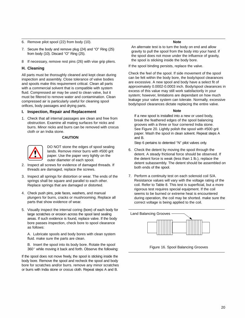
NoteIf a new spool is installed into a new or used body,break the feathered edges of the spool balancinggrooves with a three or four cornered India stone.See Figure 20. Lightly polish the spool with #500 gritpaper. Wash the spool in clean solvent. Repeat steps Aand B.Step 6 pertains to detented ‘‘N’’ pilot valves only.
6. Check the detent by moving the spool through thedetent. A steady frictional force should be observed. Ifthe detent force is weak (less than 1 lb.), replace thedetent subassembly. The detent should be assembled onboth ends of the spool.
7. Perform a continuity test on each solenoid coil S/A.Resistance values will vary with the voltage rating of thecoil. Refer to Table 8. This test is superficial, but a morerigorous test requires special equipment. If the coilseems to be burned or extreme heat is encounteredduring operation, the coil may be shorted. make sure thecorrect voltage is being applied to the coil.
Figure 16. Spool Balancing Grooves
Land Balancing Grooves
21
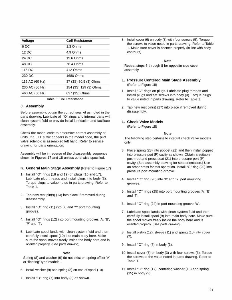
Voltage Coil Resistance
6 DC 1.3 Ohms
12 DC 4.9 Ohms
24 DC 19.6 Ohms
48 DC 78.4 Ohms
115 DC 412 Ohms
230 DC 1680 Ohms
115 AC (60 Hz) 37 (3S) 30.5 (3) Ohms
230 AC (60 Hz) 154 (3S) 129 (3) Ohms
460 AC (60 Hz) 637 (3S) Ohms
Table 8. Coil Resistance
J. Assembly
Before assembly, obtain the correct seal kit as noted in theparts drawing. Lubricate all ‘‘O’’ rings and internal parts withclean system fluid to provide initial lubrication and facilitateassembly.
Check the model code to determine correct assembly ofunits. If a L.H. suffix appears in the model code, the pilotvalve solenoid is assembled left hand. Refer to servicedrawing for parts orientation.
Assembly will be in reverse of the disassembly sequenceshown in Figures 17 and 18 unless otherwise specified.
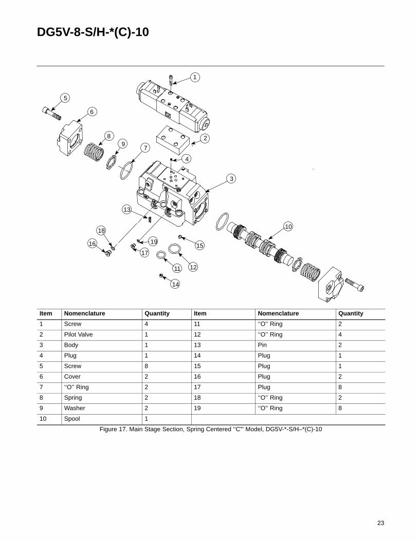
K. General Main Stage Assembly (Refer to Figure 17)
1. Install ‘‘O’’ rings (18 and 19) on plugs (16 and 17).Lubricate plug threads and install plugs into body (3).Torque plugs to value noted in parts drawing. Refer toTable 1.
2. Tap new rest pin(s) (13) into place if removed duringdisassembly.
3. Install ‘‘O’’ ring (11) into ‘X’ and ‘Y’ port mountinggrooves.
4. Install ‘‘O’’ rings (12) into port mounting grooves ‘A’, ‘B’,‘P’ and ‘T’.
5. Lubricate spool lands with clean system fluid and thencarefully install spool (10) into main body bore. Makesure the spool moves freely inside the body bore and isoriented properly. (See parts drawing).
NoteSpring (8) and washer (9) do not exist on spring offset ‘A’or ‘floating’ type models.
6. Install washer (9) and spring (8) on end of spool (10).
7. Install ‘‘O’’ ring (7) into body (3) as shown.
8. Install cover (6) on body (3) with four screws (5). Torquethe screws to value noted in parts drawing. Refer to Table1. Make sure cover is oriented properly (in line with bodycontours).
NoteRepeat steps 6 through 8 for opposite side coverassembly.
L. Pressure Centered Main Stage Assembly(Refer to Figure 18)
1. Install ‘‘O’’ rings on plugs. Lubricate plug threads andinstall plugs and set screws into body (3). Torque plugsto value noted in parts drawing. Refer to Table 1.
2. Tap new rest pin(s) (27) into place if removed duringdisassembly.
L. Check Valve Models(Refer to Figure 18)
NoteThe following step pertains to integral check valve modelsonly.
3. Place spring (23) into poppet (22) and then install poppetinto pressure port (P) cavity as shown. Obtain a suitablepush rod and press seat (21) into pressure port (P)cavity. (See assembly drawing for seat orientation.) Usean arbor press for this operation. Install ‘‘O’’ ring (20) intopressure port mounting groove.
4. Install ‘‘O’’ ring (26) into ‘X’ and ‘Y’ port mountinggrooves.
5. Install ‘‘O’’ rings (25) into port mounting grooves ‘A’, ‘B’and ‘T’.
6. Install ‘‘O’’ ring (24) in port mounting groove ‘W’.
7. Lubricate spool lands with clean system fluid and thencarefully install spool (9) into main body bore. Make surethe spool moves freely inside the body bore and isoriented properly. (See parts drawing).
8. Install piston (12), sleeve (11) and spring (10) into cover(7).
9. Install ‘‘O’’ ring (8) in body (3).
10. Install cover (7) on body (3) with four screws (6). Torquethe screws to the value noted in parts drawing. Refer toTable 1.
11. Install ‘‘O’’ ring (17), centering washer (16) and spring(15) in body (3).
22
12. Install cover (14) on body (3) with four screws (13).Torque the screws to the value noted in parts drawing.Refer to Table 1.
13. Install plugs (18) and ‘‘O’’ rings (19) into cover (7).
14 For DG3V8 models, install crossover plate (2) on body (3)with four screws (1). Torque screws to value noted inparts drawing. Refer to Table 1.
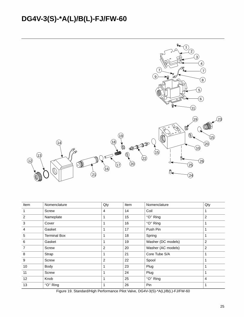
M. High/Standard Performance Pilot ValveAssembly (Refer to Figure 19)
1. Install ‘‘O’’ rings (25) on plugs (24). Lubricate plugthreads and install into body (10). Install remaining ‘‘O’’rings (25) into body (10). Torque plugs to the valueshown in parts drawing. Refer to Table 1.
2. Lubricate pilot spool (22), then carefully install spool intothe body (10).
NoteIf pilot valve is equipped with two solenoids, repeat steps3 through 7.
3. Assemble washer (19) or (20) on end of spool (22) withsharp break edge toward outside of body.
4. Install spring (18), push pin (17) and ‘‘O’’ ring (15) intobody (10).
5. Install ‘‘O’’ ring (16) on core tube S/A (21) and install coretube S/A into body (10).
6. Install ‘‘O’’ ring (13) on core tube S/A (20).
7. Install coil (14) on body (10) and secure to core tube S/A(20) with knob (12).
8. Install gasket (6) and terminal box (5) on body (10) andsecure with ground screw (11) and two screws (9).
9. Install strap (8) on terminal box (5) with two screws (7).
10. Install gasket (4), cover (3) and nameplate (2) onterminal box (5) with four screws (1).
23
DG5V-8-S/H-*(C)-10
2
79
11
5
12
10
1
3
4
6
16
13
1715
18
14
8
19
Item Nomenclature Quantity Item Nomenclature Quantity
1 Screw 4 11 ‘‘O’’ Ring 2
2 Pilot Valve 1 12 ‘‘O’’ Ring 4
3 Body 1 13 Pin 2
4 Plug 1 14 Plug 1
5 Screw 8 15 Plug 1
6 Cover 2 16 Plug 2
7 ‘‘O’’ Ring 2 17 Plug 8
8 Spring 2 18 ‘‘O’’ Ring 2
9 Washer 2 19 ‘‘O’’ Ring 8
10 Spool 1
Figure 17. Main Stage Section, Spring Centered ‘‘C”’ Model, DG5V-*-S/H–*(C)-10

24
DG3V-8-*(D)-10
25
26
2728
2
7
9
21
11
5
1210
1
3
4
6
16 13
17
15
19
18
14
8
22
23
24
20
29
Item Nomenclature Quantity Item Nomenclature Quantity
1 Screw 4 16 Centering Washer 1
2 Crossover Plate 1 17 ‘‘O’’ Ring 1
3 Body 1 18 Plug 4
4 ‘‘O’’ Ring 4 19 ‘‘O’’ Ring 1
5 Set screw 1 20 ‘‘O’’ Ring 1
6 Screw 4 21 Seat 1
7 Cover 1 22 Poppet 1
8 ‘‘O’’ Ring 2 23 Spring 1
9 Spool 2 24 ‘‘O’’ Ring 1
10 Spring 2 25 ‘‘O’’ Ring 3
11 Sleeve 1 26 ‘‘O’’ Ring 2
12 Piston 1 27 Rest Pin 2
13 Screw 4 28 Plug 1
14 Cover 1 29 ‘‘O’’ Ring 1
15 Spring 1
Figure 18. DG3V-8-*(D) (2/8/28)-10 Pressure Centered with Check Valve Options
25
DG4V-3(S)-*A(L)/B(L)-FJ/FW-60
2
7
9
21
11
5
12
10
1
3
4
6
16
13
17
15
19
1814
8
20
19
22
25
24
23
7
20
15
26
Item Nomenclature Qty Item Nomenclature Qty
1 Screw 4 14 Coil 1
2 Nameplate 1 15 ‘‘O’’ Ring 2
3 Cover 1 16 ‘‘O’’ Ring 1
4 Gasket 1 17 Push Pin 1
5 Terminal Box 1 18 Spring 1
6 Gasket 1 19 Washer (DC models) 2
7 Screw 2 20 Washer (AC models) 2
8 Strap 1 21 Core Tube S/A 1
9 Screw 2 22 Spool 1
10 Body 1 23 Plug 1
11 Screw 1 24 Plug 1
12 Knob 1 25 ‘‘O’’ Ring 4
13 ‘‘O’’ Ring 1 26 Pin 1
Figure 19. Standard/High Performance Pilot Valve, DG4V-3(S)-*A(L)/B(L)-FJ/FW-60
26
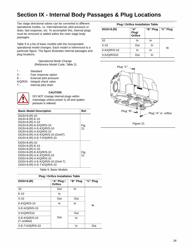
Section IX - Internal Body Passages & Plug LocationsTwo stage directional valves can be converted to differentoperational modes, i.e. internal/external, pilot pressure ordrain, fast response, etc. To accomplish this, internal plugsmust be removed or added within the main stage bodypassages.
Table 9 is a list of basic models with the incorporatedoperational model changes. Each model is referenced to aparticular figure. The figure illustrates internal passages andplug locations.
Operational Mode Change (Reference Model Code, Table 2)
* - StandardX - Fast response optionE - External pilot pressure K/Q/R/S- Integral check valveT - Internal pilot drain
CAUTIONDO NOT change internal plugs withinmainstage unless power is off and systempressure is relieved.
Basic Model Description Ref.
DG3V-8-(R)-10DG3V-8-(R)-E-10DG3V-8-(R)-X-10DG3V-8-(R)-E-K/Q/R/S-10DG3V-8-(R)-X-E-K/Q/R/S-10DG3V-8-(R)-X-K/Q/R/S-10DG3V-8-(R)-X-E-K/Q/R/S-10 (OmitT)DG3V-8-(R)-X-E-T-K/Q/R/S-10
Fig.21
DG5V-8-(R)-10DG5V-8-(R)-E-10DG5V-8-(R)-X-10DG5V-8-(R)-E-K/Q/R/S-10DG5V-8-(R)-X-E-K/Q/R/S-10DG5V-8-(R)-X-K/Q/R/S-10DG5V-8-(R)-X-E-K/Q/R/S-10 (Omit T)DG5V-8-(R)-X-E-T-K/Q/R/S-10
Fig.21
Table 9. Basic Models
Plug / Orifice Installation Table
DG3V-8-(R) ‘‘A’’Plug/Orifice
‘‘B’’ Plug ‘‘C’’ Plug
10 In In
X-10 Out InIn
X-K/Q/R/S-10 In InIn
X-K/Q/R/S10 Out In
Plug ‘‘B’’Plug ‘‘A’’ or orifice
Plug ‘‘C’’
Figure 21
Plug / Orifice Installation Table
DG5V-8-(R) ‘‘A’’ Plug /Orifice
‘‘B’’ Plug ‘‘C’’ Plug
10 Out In
E-10 In
X-10 Out Out
E-K/Q/R/S-10 In InIn
X-E-K/Q/R/S-10In
X-K/Q/R/S10 Out
X-E-K/Q/R/S-10(T omitted)
Out In
X-E-T-K/Q/R/S-10 In Out
27
Section X - Start-Up and Test
A. Start-Up
Start the system and sequence the unit through all positionswhile watching for appropriate movement of actuators.Improper or erratic movement of the actuators may indicateincorrect assembly of the unit or presence of trapped air.
B. Test
A test stand having regulated flow, temperature control andspecial fixtures is required to fully test the performance of therebuilt unit. Because of this, only the functional test shown inthe start-up paragraph is given. If such a test stand isavailable, test the unit to the requirements set forth in theinstallation drawings.