Embed Size (px)
Citation preview
VIDEAS: Supporting Answer-Set ProgramDevelopment using Model-Driven
Engineering Techniques?
Johannes Oetsch1, Jorg Puhrer1, Martina Seidl2,3,Hans Tompits1, and Patrick Zwickl4
1 Technische Universitat Wien, Institut fur Informationssysteme 184/3,Favoritenstraße 9–11, A-1040 Vienna, Austria
oetsch,puehrer,[email protected] Johannes Kepler Universitat Linz, Institut fur Formale Modelle und Verifikation,
Altenbergerstraße 69, A-4040 Linz, [email protected]
3 Technische Universitat Wien, Institut fur Softwaretechnik, 188/3Favoritenstraße 9–11, A-1040 Vienna, Austria
4 FTW Telecommunications Research Center ViennaDonau-City-Straße 1, A-1220 Vienna, Austria
Abstract. Recently, the techniques of model-driven engineering (MDE) havebeen proven valuable to manage the complexity of modern software systems dur-ing the software development process. In the area of answer-set programming(ASP), the focus is set so far on theoretical aspects, applications, and the devel-opment of efficient solvers, reducing the attention that is paid to the pragmaticsof programming and assisting tools. To address this issue, we propose the MDE-based program development method VIDEAS by introducing explicit model-to-code mappings and code generation strategies ensuring compliant specification offacts and essential constraints. Its practical applicability is realised on the basisof a prototypical implementation.
1 Introduction
Answer-set programming (ASP) [1] offers a powerful framework for declarative prob-lem solving based on principles of logic programming. The basic idea of ASP is toencode problems in terms of answer-set programs whose results (the “answer sets”)represent the solutions of the original problems. This is in contrast to traditional logic-based knowledge representation languages like Prolog where the solutions are given byproofs.? This research was partially supported by the Austrian Science Fund (FWF) under grant P21698
and the Vienna Science and Technology Fund (WWTF) under grant ICT10-018. The last au-thor would like to acknowledge additional funding from FTW Telecommunications ResearchCenter Vienna (Project U-0).
During the last decade, ASP experienced considerable attention in the academic ar-tificial intelligence community, leading to successful applications in diverse areas likeplanning, diagnosis, symbolic model checking, decision support systems, and bioinfor-matics, among others, exploiting various sophisticated solvers like DLV5 or clasp6. Sofar, ASP research mainly focused on (i) formal properties of the answer-set semantics,(ii) issues related to using it for knowledge representation and reasoning, and (iii) thedevelopment of efficient ASP solvers, being the trailblazers to the success in the aca-demic world. However, ASP could not attract the same interest as other programminglanguages outside academia. This might be because comparably little attention was paidto the development of programming methods and tools, which are arguably indispens-able to convince software engineers and programmers to take advantage of the benefitsof answer-set programming.
In particular, no graphical modelling environment as it is available in traditionalsoftware engineering in terms of the Unified Modeling Language (UML) and in tradi-tional data engineering in terms of the entity relationship diagram (ER diagram) [2]has been introduced for ASP so far. One explanation for the absence of such modellingtools may be seen in the fact that answer-set programs themselves are already definedat a high level of abstraction—in contrast to imperative programs—and may in turnbe regarded as executable specification themselves. However, practice has shown thatthe development of answer-set programs is not always straightforward and that pro-grams are, as all human-made artefacts, prone to errors. Consider, for example, thefacts airplan(boeing) and airplane(airbus). This small program excerptalready contains a mistake. A predicate name is misspelled, which might result in someunexpected program behaviour. Furthermore, most current ASP solvers do not supporttype checking. A notable exception is the DLV+ system [3] that supports typing andconcepts from object-oriented programming. If values of predicate arguments are ex-pected to come from a specific domain only, specific constraints have to be included inthe program. This requires additional programming effort and could even be a furthersource for programming errors.
To support answer-set programmers, we developed the tool VIDEAS [4], standingfor “VIsual DEsign support for Answer-Set programming”, which graphically supportsthe partial specification of answer-set programs. Due to the close relationship betweenanswer-set programs and deductive databases, in VIDEAS, ER diagrams are used asa starting point for the development of answer-set programs. The constraints on theproblem domain from an ER diagram are automatically translated to ASP itself. Havingsuch constraints as part of a problem encoding can be compared to using assertions in Cprograms. To support the development of a fact base, VIDEAS automatically generates aprogram providing an input mask for correctly specifying the facts. To realise VIDEAS,we used well-established technologies from the active field of model-driven engineering(MDE) which provides tools for building the necessary graphical modelling editors aswell as a code generator.
This paper is structured as follows. First, we review the status quo concerning thedevelopment support for answer-set programs in Section 2. Then, after some back-
5 http://www.dlvsystem.com.6 http://potassco.sourceforge.net.
ground on ASP in Section 3, we present the basic ideas of the VIDEAS approach whereER diagrams serve as starting point for the program development and visualisation inSection 4. To this end, we introduce a mapping between ER diagrams and ASP in Sec-tion 5. Finally, we discuss the implementation in Section 6 and conclude with an outlookto future work in Section 7.
2 Related Work
For assisting the development of answer-set programs, much research effort is recentlyspent in debugging. For example, debugging concepts for inconsistent answer-sets [5]and model extensions [6] have been proposed. Likewise, debugging methodologies likerecursive ASP debugging [7, 8], meta-programming techniques [9, 10], translational de-bugging reformulating programs in natural language [11], justification concepts fortruth values [12], or stepping [13] have been developed. However, only limited effortis spent on directly supporting the construction phase of programs with few exceptionslike the specification of services with preferences by Confalonieri et al. [14]. There arealso efforts towards the realisation of integrated development environments (IDEs), likeAPE [15], ASPIDE [16], SeaLion [17], and iGROM 7, as well as for systems allowingthe visualisation of answer sets, as done in the systems ASPVIZ [18], IDPDraw8, and,most recently, the Kara [19] plugin of SeaLion.
To derive certain consistency constraints for ensuring data-model compliance withthe program code, Sureshkumar et al. [15] use dependency graphs while Konczak etal. [20] use colored graphs.
Similar approaches have been introduced by Kehrer and Neumann [21] and byAmalfi and Provetti [22], where it is proposed to derive logic programs from extendedER diagrams (EER diagrams). The intention behind that work was not to support thedevelopment of ASP programs, but to use the inference mechanisms of logic program-ming to reason about the instances of the database.
VisualASP [23] and ASPIDE [16] offer an environment for the graphical speci-fication of answer-set programs by providing an editor for directly visualising the ASPconcepts. VIDEAS, in contrast, takes advantage of the abstraction power of the ER di-agram and adopts the query by a diagram approach (cf. the survey article by Catarciet al. [24]) for program specification. On the other hand, a fact generator concept asgiven by Chirila et al. [25]—a language-independent generator of facts for logics—istransferred to ASP.
Overall, we are not aware of any solutions for introducing modelling techniquesinto the ASP context as we discuss in the next sections.
3 Preliminaries
In this section, we recapitulate the basics of ASP. For more details, we refer to the liter-ature [1]. An answer-set program, Π , or program for short, is defined over an alphabet
7 http://igrom.sourceforge.net/.8 https://dtai.cs.kuleuven.be/krr/software/visualisation.
AASP = (P,C, V ), where P , C, and V are finite and non-empty sets of predicate sym-bols, constant symbols, and variables, respectively. Each predicate symbol is assumedto have a unique natural number assigned, called its arity. A term is either a variablefrom V or a constant from C. An atom is an expression of the form p(t1, . . . , tn),where p is a predicate symbol of arity n ≥ 0 from P , and t1, . . . , tn are terms. A literalis either an atom p or a negated atom ¬p. The symbol “¬” is referred to as strong nega-tion. Besides strong negation, there is a second, weaker form of negation, called defaultnegation, written “not”. Intuitively, not p states that p cannot be proved, where p is aliteral. That is, default negation corresponds to negation as failure.
A rule, r, is an expression of the form
h :− b1, . . . , bk, not bk+1, . . . , not bn,
where h, b1, . . . , bn are literals with n ≥ 0. The informal meaning of rule r is that h isasserted whenever b1, . . . , bn are derivable whilst bk+1, . . . , bn are not derivable. Theliteral h is called the head of r and b1, . . . , bk, not bk+1, . . . , not bn form the body ofr. A rule is a fact if its body is empty, and a constraint if its head is empty. The intuitivereading of a constraint is that it is forbidden that all literals b1, . . . , bk are true but noneof bk+1, . . . , bn are true. For facts, usually the symbol “: − ” is omitted. We refer torules which are neither constraints nor facts as proper rules. An atom, a literal, or a ruleis called ground if it does not contain any variables. An answer-set program is a set ofrules. We call a program positive if none of its rules contains a default-negated literal.In the following, the language of ASP is referred to as LASP.
The semantics of answer-set programs is defined in terms of consistent sets of liter-als representing three-valued interpretations (true, false, undefined). Programs withoutdefault negation are associated with their least satisfying consistent set of literals. Ifno such set can be found, the program is inconsistent. The semantics of programs con-taining default negation is defined by a reduction to the least model semantics via theGelfond-Lifschitz transformation. For a formal definition of the semantics, we refer tothe textbook by Baral [1].
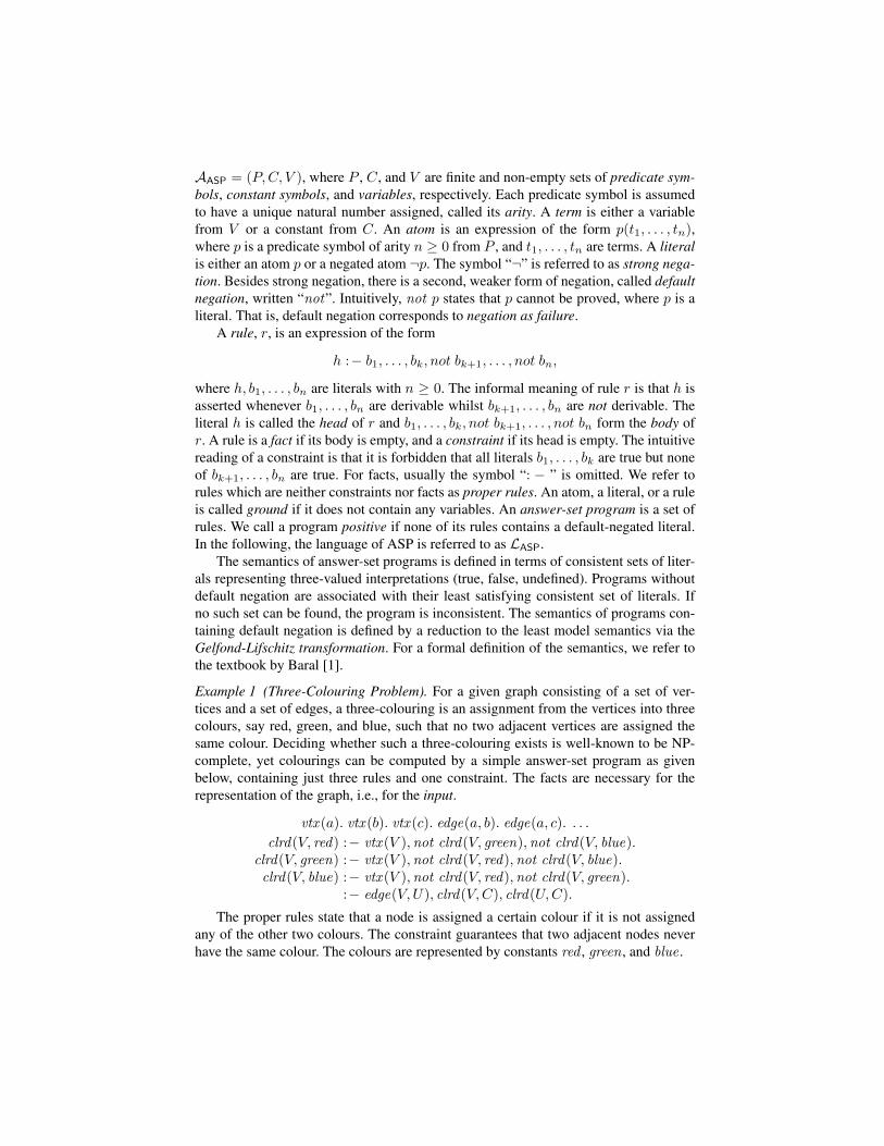
Example 1 (Three-Colouring Problem). For a given graph consisting of a set of ver-tices and a set of edges, a three-colouring is an assignment from the vertices into threecolours, say red, green, and blue, such that no two adjacent vertices are assigned thesame colour. Deciding whether such a three-colouring exists is well-known to be NP-complete, yet colourings can be computed by a simple answer-set program as givenbelow, containing just three rules and one constraint. The facts are necessary for therepresentation of the graph, i.e., for the input.
vtx (a). vtx (b). vtx (c). edge(a, b). edge(a, c). . . .
clrd(V, red) :− vtx (V ),not clrd(V, green),not clrd(V, blue).clrd(V, green) :− vtx (V ),not clrd(V, red),not clrd(V, blue).clrd(V, blue) :− vtx (V ),not clrd(V, red),not clrd(V, green).
:− edge(V,U), clrd(V,C), clrd(U,C).
The proper rules state that a node is assigned a certain colour if it is not assignedany of the other two colours. The constraint guarantees that two adjacent nodes neverhave the same colour. The colours are represented by constants red , green , and blue .
Modeling Editor
Code Generator
Data Model
VIDEAS
Editor GeneratorModel
Data Engineer
Fact Builder
ASP C dSecretary
Rules Facts Constraints
ASP Code
ASP Solver
Programmer
Answer Sets
input
generate
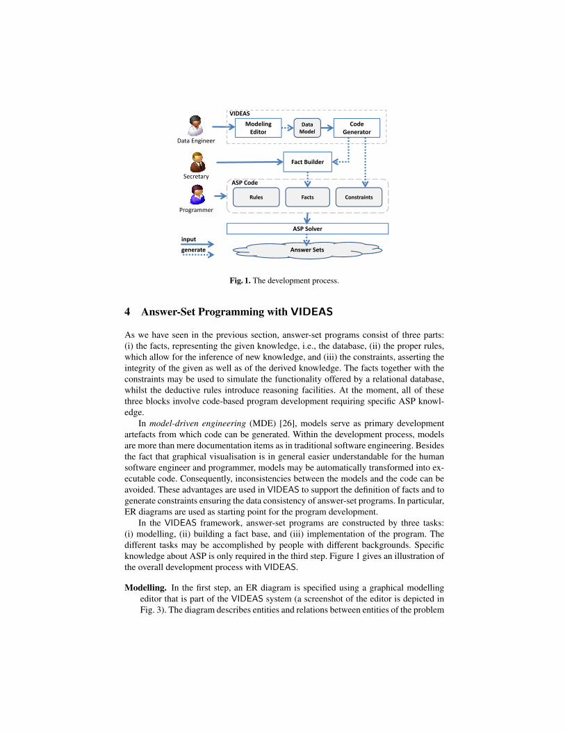
Fig. 1. The development process.
4 Answer-Set Programming with VIDEAS
As we have seen in the previous section, answer-set programs consist of three parts:(i) the facts, representing the given knowledge, i.e., the database, (ii) the proper rules,which allow for the inference of new knowledge, and (iii) the constraints, asserting theintegrity of the given as well as of the derived knowledge. The facts together with theconstraints may be used to simulate the functionality offered by a relational database,whilst the deductive rules introduce reasoning facilities. At the moment, all of thesethree blocks involve code-based program development requiring specific ASP knowl-edge.
In model-driven engineering (MDE) [26], models serve as primary developmentartefacts from which code can be generated. Within the development process, modelsare more than mere documentation items as in traditional software engineering. Besidesthe fact that graphical visualisation is in general easier understandable for the humansoftware engineer and programmer, models may be automatically transformed into ex-ecutable code. Consequently, inconsistencies between the models and the code can beavoided. These advantages are used in VIDEAS to support the definition of facts and togenerate constraints ensuring the data consistency of answer-set programs. In particular,ER diagrams are used as starting point for the program development.
In the VIDEAS framework, answer-set programs are constructed by three tasks:(i) modelling, (ii) building a fact base, and (iii) implementation of the program. Thedifferent tasks may be accomplished by people with different backgrounds. Specificknowledge about ASP is only required in the third step. Figure 1 gives an illustration ofthe overall development process with VIDEAS.
Modelling. In the first step, an ER diagram is specified using a graphical modellingeditor that is part of the VIDEAS system (a screenshot of the editor is depicted inFig. 3). The diagram describes entities and relations between entities of the problem
Airplane
AirplaneType
is_of
regNo
name size
Airportbased neighbour
ID
capacity
n
1
1n
n
m
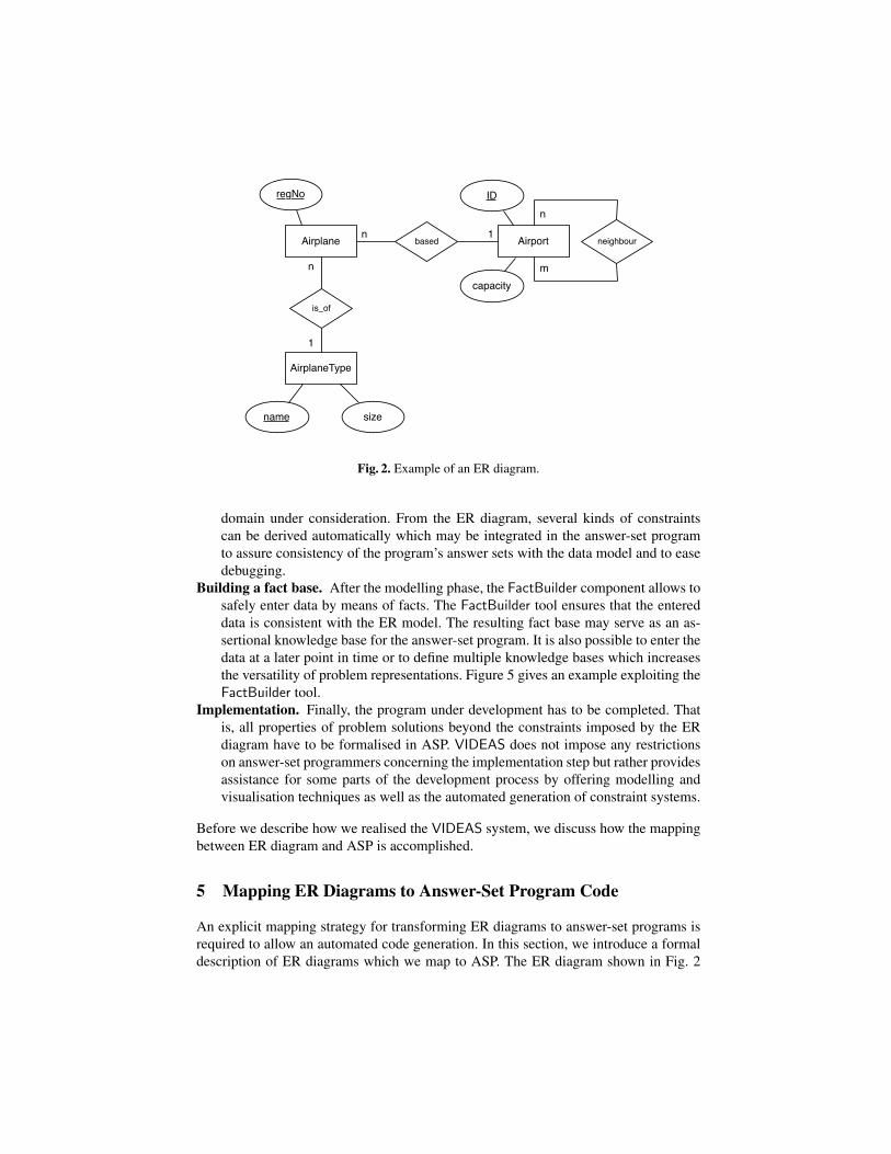
Fig. 2. Example of an ER diagram.
domain under consideration. From the ER diagram, several kinds of constraintscan be derived automatically which may be integrated in the answer-set programto assure consistency of the program’s answer sets with the data model and to easedebugging.
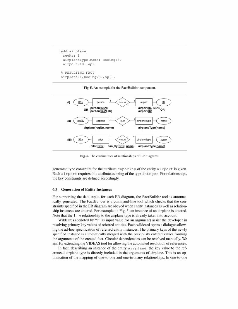
Building a fact base. After the modelling phase, the FactBuilder component allows tosafely enter data by means of facts. The FactBuilder tool ensures that the entereddata is consistent with the ER model. The resulting fact base may serve as an as-sertional knowledge base for the answer-set program. It is also possible to enter thedata at a later point in time or to define multiple knowledge bases which increasesthe versatility of problem representations. Figure 5 gives an example exploiting theFactBuilder tool.
Implementation. Finally, the program under development has to be completed. Thatis, all properties of problem solutions beyond the constraints imposed by the ERdiagram have to be formalised in ASP. VIDEAS does not impose any restrictionson answer-set programmers concerning the implementation step but rather providesassistance for some parts of the development process by offering modelling andvisualisation techniques as well as the automated generation of constraint systems.
Before we describe how we realised the VIDEAS system, we discuss how the mappingbetween ER diagram and ASP is accomplished.
5 Mapping ER Diagrams to Answer-Set Program Code
An explicit mapping strategy for transforming ER diagrams to answer-set programs isrequired to allow an automated code generation. In this section, we introduce a formaldescription of ER diagrams which we map to ASP. The ER diagram shown in Fig. 2
serves as illustrating example which will be represented as an answer-set program. Notethat we use only standard concepts of ASP as described in Section 3, but no solver-specific language extensions. Furthermore, for the sake of simplicity, we consider hereonly a subset of the language of ER diagrams—in particular, we do not consider arbi-trary cardinality constraints.
Let LER be the language of ER diagrams defined over an alphabetAER=(R,A,D),where R denotes a set of relations, A denotes a set of attributes, and D is a non-emptyset called domain. Each attribute a ∈ A is assigned with its associated domain d(a),which is a subset of D, i.e., d(a) ⊆ D. In the ER diagram of Fig. 2, Airplane/1and based/2 are examples for relations, ID is an example for an attribute, and thenumbers, referred to as integer/1, are elements of the domain.
In view of our purposes, we define an ER diagram Ω ∈ LER as a triple (E,R, k),consisting of a set E of entities, a set R of relationships, and a function k : E → Ndefining the primary key for each entity. In the following, we introduce these conceptsiteratively and provide a mapping σα : LER × I → LASP from the language LER ofER diagrams, along with the set I of all instances of entities, to the language LASP ofanswer-set programs, parametrised by a mapping α relating the respective alphabets,which will be formally introduced first.
Definition 1 (Symbol Mapping). Given a language LER over an alphabet AER =(R,A,D) and a language LASP over an alphabet AASP = (P,C, V ), a symbol map-ping is an injective function α : R ∪A ∪D → P ∪ C ∪ V such that (i) for any r ∈ R,α(r) ∈ P , where r and α(r) have the same arity, (ii) for any a ∈ A, α(a) ∈ V , and(iii) for any d ∈ D, α(d) ∈ C.
Hence, according to this definition, in an answer-set program, relations are repre-sented by predicate symbols, attributes are represented by variables, and elements ofthe domain are represented by constants. Furthermore, a symbol mapping is stipulatedto be injective, which means that for all elements x, y of its domain, we have that x 6= yimplies α(x) 6= α(x). From the definition of a function, this implies in turn that x 6= yholds precisely in case α(x) 6= α(y) holds. Thus, all terms are uniquely identifiable.
Definition 2 (Entity). Let AER = (R,A,D) be an alphabet. An entity over AER is anexpression of the form e(a1, . . . , an) with e ∈ R and a1, . . . , an ∈ A such that, forevery attribute ai and aj , 1 ≤ i, j ≤ n, it holds that ai 6= aj iff i 6= j. An instance ofan entity e(a1, . . . , an) is an expression of the form e(w1, . . . , wn), where wi ∈ d(ai),for every 1 ≤ i ≤ n. The term wi is called a value of attribute ai.
An entity is hence characterised by its attributes which in turn range over a givendomain. In an ER diagram, an entity is visualised by a rectangle containing the name ofthe entity and the attributes are represented as ellipses which are attached to the entitythey belong to. In Fig. 2, Airport(ID, capacity) and Airplane(regNo) areexamples of entities. Instances are not part of an ER diagram, but they can be seen asactual entries of a database which is realised according to the schema defined by the ERdiagram. For instance, Airport(‘‘vienna’’, 500) would be an example for aninstance in the ER diagram of Fig. 2.
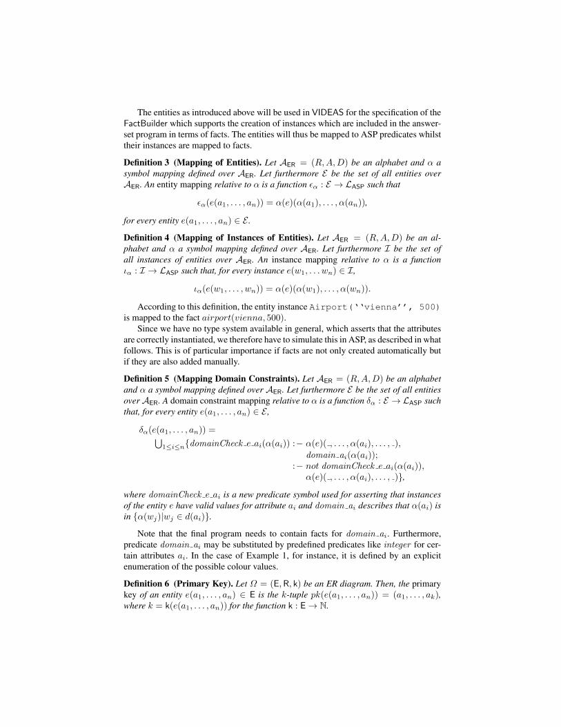
The entities as introduced above will be used in VIDEAS for the specification of theFactBuilder which supports the creation of instances which are included in the answer-set program in terms of facts. The entities will thus be mapped to ASP predicates whilsttheir instances are mapped to facts.
Definition 3 (Mapping of Entities). Let AER = (R,A,D) be an alphabet and α asymbol mapping defined over AER. Let furthermore E be the set of all entities overAER. An entity mapping relative to α is a function εα : E → LASP such that
εα(e(a1, . . . , an)) = α(e)(α(a1), . . . , α(an)),
for every entity e(a1, . . . , an) ∈ E .
Definition 4 (Mapping of Instances of Entities). Let AER = (R,A,D) be an al-phabet and α a symbol mapping defined over AER. Let furthermore I be the set ofall instances of entities over AER. An instance mapping relative to α is a functionια : I → LASP such that, for every instance e(w1, . . . wn) ∈ I,
ια(e(w1, . . . , wn)) = α(e)(α(w1), . . . , α(wn)).
According to this definition, the entity instance Airport(‘‘vienna’’, 500)is mapped to the fact airport(vienna, 500).
Since we have no type system available in general, which asserts that the attributesare correctly instantiated, we therefore have to simulate this in ASP, as described in whatfollows. This is of particular importance if facts are not only created automatically butif they are also added manually.
Definition 5 (Mapping Domain Constraints). Let AER = (R,A,D) be an alphabetand α a symbol mapping defined over AER. Let furthermore E be the set of all entitiesoverAER. A domain constraint mapping relative to α is a function δα : E → LASP suchthat, for every entity e(a1, . . . , an) ∈ E ,
δα(e(a1, . . . , an)) =⋃1≤i≤ndomainCheck e ai(α(ai)) :− α(e)( , . . . , α(ai), . . . , ),
domain ai(α(ai));:− not domainCheck e ai(α(ai)),
α(e)( , . . . , α(ai), . . . , ),
where domainCheck e ai is a new predicate symbol used for asserting that instancesof the entity e have valid values for attribute ai and domain ai describes that α(ai) isin α(wj)|wj ∈ d(ai).
Note that the final program needs to contain facts for domain ai . Furthermore,predicate domain ai may be substituted by predefined predicates like integer for cer-tain attributes ai. In the case of Example 1, for instance, it is defined by an explicitenumeration of the possible colour values.
Definition 6 (Primary Key). Let Ω = (E,R, k) be an ER diagram. Then, the primarykey of an entity e(a1, . . . , an) ∈ E is the k-tuple pk(e(a1, . . . , an)) = (a1, . . . , ak),where k = k(e(a1, . . . , an)) for the function k : E→ N.
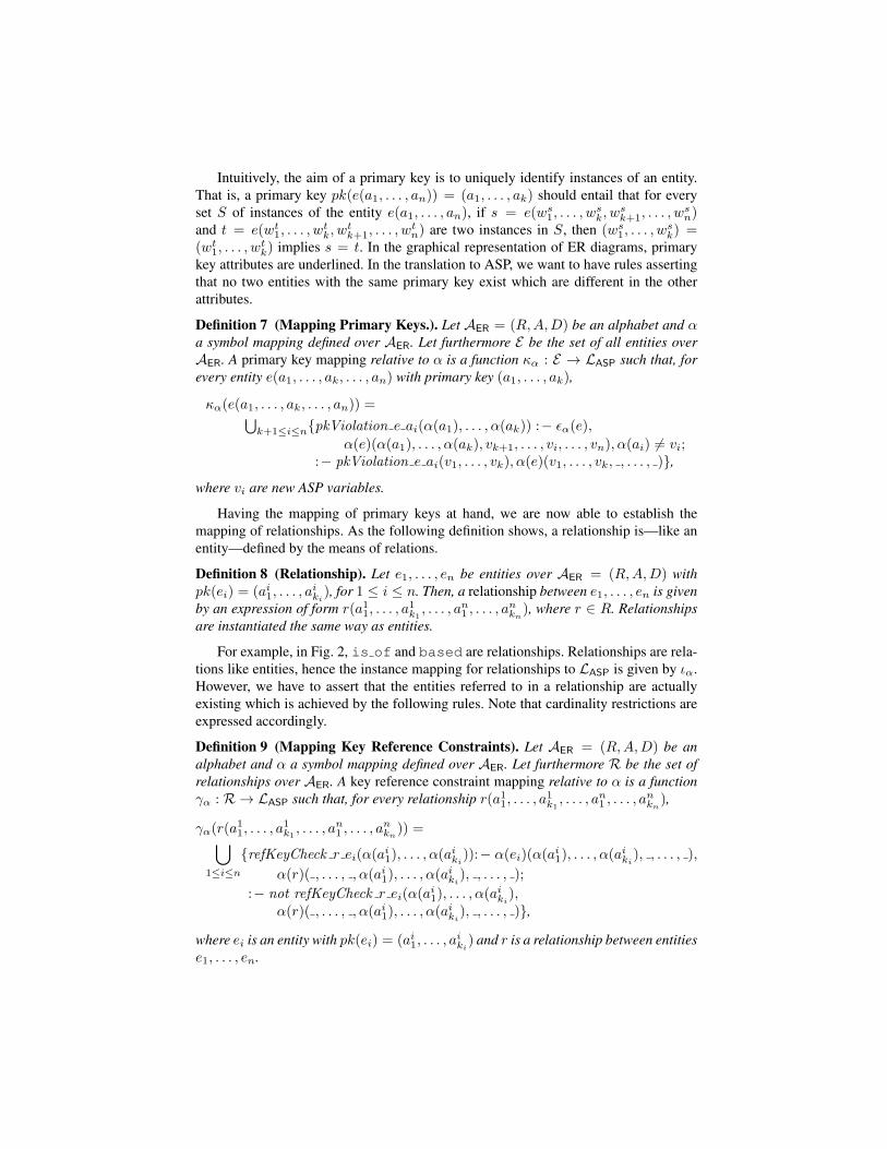
Intuitively, the aim of a primary key is to uniquely identify instances of an entity.That is, a primary key pk(e(a1, . . . , an)) = (a1, . . . , ak) should entail that for everyset S of instances of the entity e(a1, . . . , an), if s = e(ws1, . . . , w
sk, w
sk+1, . . . , w
sn)
and t = e(wt1, . . . , wtk, w
tk+1, . . . , w
tn) are two instances in S, then (ws1, . . . , w
sk) =
(wt1, . . . , wtk) implies s = t. In the graphical representation of ER diagrams, primary
key attributes are underlined. In the translation to ASP, we want to have rules assertingthat no two entities with the same primary key exist which are different in the otherattributes.
Definition 7 (Mapping Primary Keys.). Let AER = (R,A,D) be an alphabet and αa symbol mapping defined over AER. Let furthermore E be the set of all entities overAER. A primary key mapping relative to α is a function κα : E → LASP such that, forevery entity e(a1, . . . , ak, . . . , an) with primary key (a1, . . . , ak),
κα(e(a1, . . . , ak, . . . , an)) =⋃k+1≤i≤npkViolation e ai(α(a1), . . . , α(ak)) :− εα(e),
α(e)(α(a1), . . . , α(ak), vk+1, . . . , vi, . . . , vn), α(ai) 6= vi;:− pkViolation e ai(v1, . . . , vk), α(e)(v1, . . . , vk, , . . . , ),
where vi are new ASP variables.
Having the mapping of primary keys at hand, we are now able to establish themapping of relationships. As the following definition shows, a relationship is—like anentity—defined by the means of relations.
Definition 8 (Relationship). Let e1, . . . , en be entities over AER = (R,A,D) withpk(ei) = (ai1, . . . , a
iki), for 1 ≤ i ≤ n. Then, a relationship between e1, . . . , en is given
by an expression of form r(a11, . . . , a1k1, . . . , an1 , . . . , a
nkn), where r ∈ R. Relationships
are instantiated the same way as entities.
For example, in Fig. 2, is of and based are relationships. Relationships are rela-tions like entities, hence the instance mapping for relationships to LASP is given by ια.However, we have to assert that the entities referred to in a relationship are actuallyexisting which is achieved by the following rules. Note that cardinality restrictions areexpressed accordingly.
Definition 9 (Mapping Key Reference Constraints). Let AER = (R,A,D) be analphabet and α a symbol mapping defined over AER. Let furthermore R be the set ofrelationships over AER. A key reference constraint mapping relative to α is a functionγα : R → LASP such that, for every relationship r(a11, . . . , a
1k1, . . . , an1 , . . . , a
nkn),
γα(r(a11, . . . , a
1k1 , . . . , a
n1 , . . . , a
nkn)) =⋃
1≤i≤n
refKeyCheck r ei(α(ai1), . . . , α(a
iki)):− α(ei)(α(ai1), . . . , α(aiki), , . . . , ),
α(r)( , . . . , , α(ai1), . . . , α(aiki), , . . . , );
:− not refKeyCheck r ei(α(ai1), . . . , α(a
iki),
α(r)( , . . . , , α(ai1), . . . , α(aiki), , . . . , ),
where ei is an entity with pk(ei) = (ai1, . . . , aiki) and r is a relationship between entities
e1, . . . , en.
Now, we have introduced all components for defining a mapping from ER diagramsto answer-set programs which is summarised by the following definition:
Definition 10. Let AER be an alphabet and α a symbol mapping over AER. Further-more, let I be the set of all instances of entities overAER. Then, σα : LER×I → LASP
is the partial function mapping an ER diagram Ω = (E,R, k) over alphabet AER and aset I ⊆ I of instances into a program over language LASP given by
σα(Ω, I) =⋃i∈I
ια(i) ∪⋃e∈E
κα(e) ∪⋃r∈R
γα(r) ∪⋃e∈E
δα(e),
providing I contains only instances of entities in E, otherwise σα(Ω, I) is undefined.
With the function σα at hand, we are able to translate the information given byan ER diagram along with instances provided by the FactBuilder to a correspondinganswer-set program. Note that the full program developed during the modelling phasemay need to make use of entities in terms of their translation under εα. In the followingsection, we discuss how σα is actually implemented in VIDEAS.
6 Implementation
6.1 General Aspects
With VIDEAS, we provide a framework which supports the development of answer-set programs by providing an editor for creating ER diagrams from which ASP codemay be derived as discussed in the previous section. In particular, constraints are au-tomatically created. To establish the database, i.e., for entering the instances of the ERdiagram, manual user input is required. Based on the constraints specified in the ERdiagram, the FactBuilder tool is automatically generated which provides an input maskfor specifying of the actual data. It asserts that the constraints are obeyed by the user.
VIDEAS has been implemented on top of the Eclipse platform9; the implementationis available at
https://subversion.assembla.com/svn/videas/.
In particular, technologies provided by the Eclipse Modeling Framework (EMF)10 andthe Graphical Modeling Framework (GMF)11 projects have been used. The meta-modelrepresenting the ER diagram modelling language has been created using the Ecoremodelling language which is specified within the EMF project. Based on this Ecoremodel (an implementation for a subset of the Meta Object Facility12), a graphical ed-itor has been created using GMF. The models created by the graphical model editorare stored as Ecore XML, models being accessible by EMF libraries, which is a pre-requisite for the code generation. Visually, n-ary relationships, for arbitrary n, can be
9 https://www.eclipse.org.10 http://www.eclipse.org/modeling/emf/.11 http://www.eclipse.org/modeling/gmf/.12 http://www.omg.org/mof/.
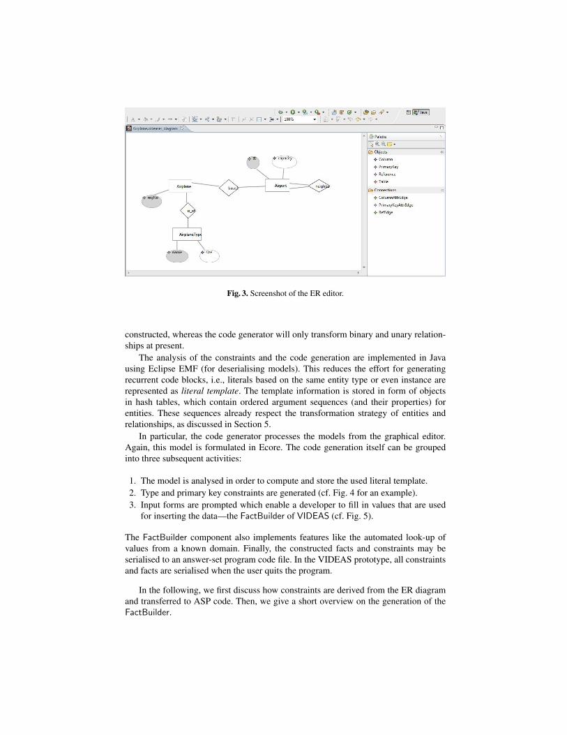
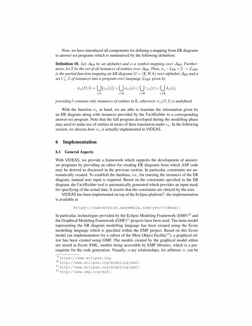
Fig. 3. Screenshot of the ER editor.
constructed, whereas the code generator will only transform binary and unary relation-ships at present.
The analysis of the constraints and the code generation are implemented in Javausing Eclipse EMF (for deserialising models). This reduces the effort for generatingrecurrent code blocks, i.e., literals based on the same entity type or even instance arerepresented as literal template. The template information is stored in form of objectsin hash tables, which contain ordered argument sequences (and their properties) forentities. These sequences already respect the transformation strategy of entities andrelationships, as discussed in Section 5.
In particular, the code generator processes the models from the graphical editor.Again, this model is formulated in Ecore. The code generation itself can be groupedinto three subsequent activities:
1. The model is analysed in order to compute and store the used literal template.2. Type and primary key constraints are generated (cf. Fig. 4 for an example).3. Input forms are prompted which enable a developer to fill in values that are used
for inserting the data—the FactBuilder of VIDEAS (cf. Fig. 5).
The FactBuilder component also implements features like the automated look-up ofvalues from a known domain. Finally, the constructed facts and constraints may beserialised to an answer-set program code file. In the VIDEAS prototype, all constraintsand facts are serialised when the user quits the program.
In the following, we first discuss how constraints are derived from the ER diagramand transferred to ASP code. Then, we give a short overview on the generation of theFactBuilder.
%%%%%% PRIMARY KEY CONSTRAINT
pkViolation_airport_capacity(ID) :- airport(ID, Capacity),airport(ID, Capacity2),Capacity != Capacity2.
:- pkViolation_airport_capacity(ID), airport(ID,_).
%%%%%% REFERENCE TYPE CONSTRAINT
refKeyCheck_isOf_airplaneType(TypeName) :-airplaneType(TypeName,_),airplane(_,TypeName,_).
:- not refKeyCheck_isOf_airplaneType(TypeName),airplane(_,TypName,_).
%%%%%% DOMAIN CONSTRAINT
domainCheck_airport_capacity(Capacity) :- airport(_, Capacity),integer(Capacity).
:- not domainCheck_airport_capacity(Capacity),airport(_, Capacity).
Fig. 4. Excerpt of constraints generated from an ER diagram.
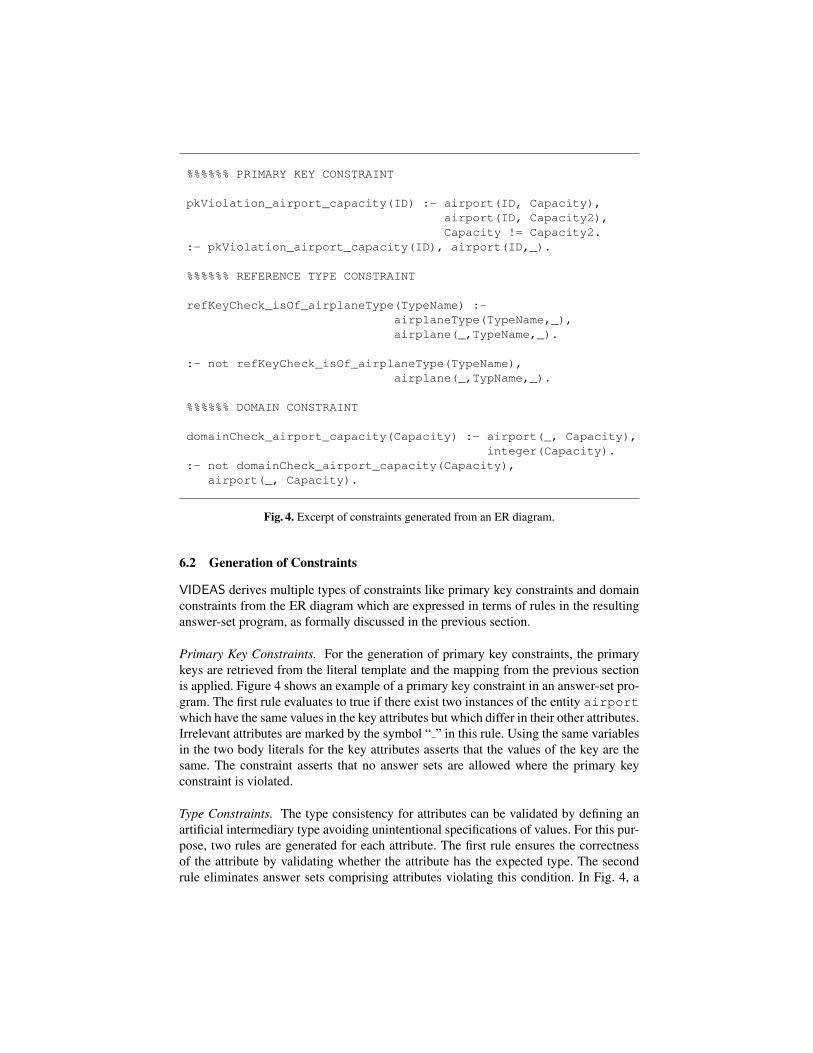
6.2 Generation of Constraints
VIDEAS derives multiple types of constraints like primary key constraints and domainconstraints from the ER diagram which are expressed in terms of rules in the resultinganswer-set program, as formally discussed in the previous section.
Primary Key Constraints. For the generation of primary key constraints, the primarykeys are retrieved from the literal template and the mapping from the previous sectionis applied. Figure 4 shows an example of a primary key constraint in an answer-set pro-gram. The first rule evaluates to true if there exist two instances of the entity airportwhich have the same values in the key attributes but which differ in their other attributes.Irrelevant attributes are marked by the symbol “ ” in this rule. Using the same variablesin the two body literals for the key attributes asserts that the values of the key are thesame. The constraint asserts that no answer sets are allowed where the primary keyconstraint is violated.
Type Constraints. The type consistency for attributes can be validated by defining anartificial intermediary type avoiding unintentional specifications of values. For this pur-pose, two rules are generated for each attribute. The first rule ensures the correctnessof the attribute by validating whether the attribute has the expected type. The secondrule eliminates answer sets comprising attributes violating this condition. In Fig. 4, a
:add airplaneregNr: 1airplaneType.name: Boeing737airport.ID: ap1
% RESULTING FACTairplane(1,Boeing737,ap1).
Fig. 5. An example for the FactBuilder component.
airplane airplaneTypeis_of 1n
person airportboss_of 11
pilot airplaneTypecan_flymn
airport(ID, SSN)
SSN ID
nameregNo
SSN name
person(SSN)
airplaneType(name) airplane(regNo, name)
airport(ID) person(SSN, ID)OR OR
pilot(SSN) can_fly(SSN, name) airplaneType(name)
(i)
(ii)
(iii)
Fig. 6. The cardinalities of relationships of ER diagrams.
generated type constraint for the attribute capacity of the entity airport is given.Each airport requires this attribute as being of the type integer. For relationships,the key constraints are defined accordingly.
6.3 Generation of Entity Instances
For supporting the data input, for each ER diagram, the FactBuilder tool is automat-ically generated. The FactBuilder is a command-line tool which checks that the con-straints specified in the ER diagram are obeyed when entity instances as well as relation-ship instances are entered. For example, in Fig. 5, an instance of an airplane is entered.Note that the 1 : n relationship to the airplane type is already taken into account.
Wildcards (denoted by “?” as input value for an argument) assist the developer inresolving primary key values of referred entities. Each wildcard opens a dialogue allow-ing the ad-hoc specification of referred entity instances. The primary keys of the newlyspecified instance is automatically merged with the previously entered values formingthe arguments of the created fact. Circular dependencies can be resolved manually. Weaim for extending the VIDEAS tool for allowing the automated resolution of references.
In fact, describing an instance of the entity airplane, the key value to the ref-erenced airplane type is directly included in the arguments of airplane. This is an op-timisation of the mapping of one-to-one and one-to-many relationships. In one-to-one
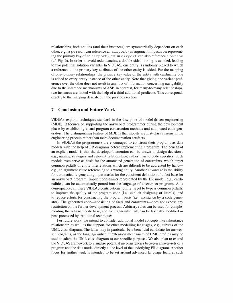
relationships, both entities (and their instances) are symmetrically dependent on eachother, e.g., a person can reference an airport (an argument in person represent-ing the primary key of an airport), but an airport can also reference a person(cf. Fig. 6). In order to avoid redundancies, a double-sided linking is avoided, leadingto two potential solution variants. In VIDEAS, one entity is randomly picked to whicha reference to the primary key attributes of the other entity is added. For the mappingof one-to-many relationships, the primary key value of the entity with cardinality oneis added to every entity instance of the other entity. Note that giving one variant pref-erence over the other does not result in any loss of information concerning navigabilitydue to the inference mechanisms of ASP. In contrast, for many-to-many relationships,two instances are linked with the help of a third additional predicate. This correspondsexactly to the mapping described in the previous section.
7 Conclusion and Future Work
VIDEAS exploits techniques standard in the discipline of model-driven engineering(MDE). It focuses on supporting the answer-set programmer during the developmentphase by establishing visual program construction methods and automated code gen-erators. The distinguishing feature of MDE is that models are first-class citizens in theengineering process rather than mere documentation artefacts.
In VIDEAS the programmers are encouraged to construct their programs as datamodels with the help of ER diagrams before implementing a program. The benefit ofan explicit model is that the developer’s attention can be drawn to design decisions,e.g., naming strategies and relevant relationships, rather than to code specifics. Suchmodels even serve as basis for the automated generation of constraints, which targetcommon pitfalls of entity interrelations which are difficult to be addressed by hand—e.g., an argument value referencing to a wrong entity. Another advantage is the abilityfor automatically generating input masks for the consistent definition of a fact base foran answer-set program. Implicit constraints represented by the ER model, e.g., cardi-nalities, can be automatically ported into the language of answer-set programs. As aconsequence, all these VIDEAS contributions jointly target to bypass common pitfalls,to improve the quality of the program code (i.e., explicit designing of literals), andto reduce efforts for constructing the program basis (i.e., assistance by a code gener-ator). The generated code—consisting of facts and constraints—does not expose anyrestriction on the further development process. Arbitrary rules can be used for comple-menting the returned code base, and each generated rule can be textually modified orpost-processed by traditional techniques.
For future work, we intend to consider additional model concepts like inheritancerelationship as well as the support for other modelling languages, e.g., subsets of theUML class diagram. The latter may in particular be a beneficial candidate for answer-set programs, as the language-inherent extension mechanism of UML profiles may beused to adapt the UML class diagram to our specific purposes. We also plan to extendthe VIDEAS framework to visualise potential inconsistencies between answer-sets of aprogram and the data model directly at the level of the underlying ER diagram. Anotherfocus for further work is intended to be set around advanced language features such
as relationships involving an arbitrary number of entities. Finally, the full potential ofVIDEAS is exploited if it is included in an integrated development environment likeASPIDE [16] or SeaLion [17].
References
1. Baral, C.: Knowledge Representation, Reasoning, and Declarative Problem Solving. Cam-bridge University Press, Cambridge, England (2003)
2. Chen, P.: The entity-relationship model—Toward a unified view of data. ACM Transactionson Database Systems 1(1) (1976) 9–36
3. Ricca, F., Leone, N.: Disjunctive logic programming with types and objects: The DLV+
system. Journal of Applied Logic 5(3) (2007) 545–5734. Oetsch, J., Puhrer, J., Seidl, M., Tompits, H., Zwickl, P.: VIDEAS: A development tool for
answer-set programs based on model-driven engineering technology. In: Proc. LPNMR’11.Volume 6645 of LNCS, Springer (2011) 382–387
5. Syrjanen, T.: Debugging inconsistent answer set programs. In: Proc. NMR’06. (2006) 77–836. Wittocx, J., Vlaeminck, H., Denecker, M.: Debugging for model expansion. In: Proc.
ICLP’09. Volume 5649 of LNCS, Springer (2009) 296–3117. Brain, M., De Vos, M.: Debugging logic programs under the answer-set semantics. In: Proc.
ASP’05. Volume 142 of CEUR Workshop Proc., CEUR-WS.org (2005) 141–1528. Brain, M., Gebser, M., Puhrer, J., Schaub, T., Tompits, H., Woltran, S.: Debugging ASP
programs by means of ASP. In: Proc. LPNMR’07. Volume 4483 of LNCS, Springer (2007)31–43
9. Gebser, M., Puhrer, J., Schaub, T., Tompits, H.: A meta-programming technique for debug-ging answer-set programs. In: Proc. AAAI’08, AAAI Press (2008) 448–453
10. Oetsch, J., Puhrer, J., Tompits, H.: Catching the Ouroboros: On debugging non-groundanswer-set programs. Theory and Practice of Logic Programming 10(4-6) (2010) 513–529
11. Mikitiuk, A., Moseley, E., Truszczynski, M.: Towards debugging of answer-set programs inthe language PSpb. In: Proc. ICAI’07, CSREA Press (2007) 635–640
12. Pontelli, E., Son, T.C., El-Khatib, O.: Justifications for logic programs under answer setsemantics. Theory and Practice of Logic Programming 9(1) (2009) 1–56
13. Johannes Oetsch, Jorg Puhrer, H.T.: Stepping through an answer-set program. In: Proc.LPNMR’11. Volume 6645 of LNCS, Springer (2011) 134–147
14. Confalonieri, R., Nieves, J.C., Vazquez-Salceda, J.: A preference meta-model for logic pro-grams with possibilistic ordered disjunction. In: Proc. SEA’09. (2009) 19–33
15. Sureshkumar, A., De Vos, M., Brain, M., Fitch, J.: APE: An AnsProlog* environment. In:Proc. SEA’07. (2007) 71–85
16. Febbraro, O., Reale, K., Ricca, F.: ASPIDE: Integrated development environment for answerset programming. In: Proc. LPNMR’11. Volume 6645 of LNCS, Springer (2011) 317–330
17. Oetsch, J., Puhrer, J., Tompits, H.: The SeaLion has landed: An IDE for answer-setprogramming—Preliminary report (2011). Submitted draft.
18. Cliffe, O., De Vos, M., Brain, M., Padget, J.A.: ASPVIZ: Declarative visualisation andanimation using answer set programming. In: Proc. ICLP’08. Volume 5366 of LNCS, (2008)724–728
19. Kloimullner, C., Oetsch, J., Puhrer, J., Tompits, H.: Kara: A system for visualising andvisual editing of interpretations (2011). Submitted draft.
20. Konczak, K., Linke, T., Schaub, T.: Graphs and colorings for answer set programming.Theory and Practice of Logic Programming 6(1-2) (2006) 61–106
21. Kehrer, N., Neumann, G.: An EER prototyping environment and its implementation in adatalog language. In: Proc. ER’92. Volume 645 of LNCS, Springer (1992) 243–261
22. Amalfi, M., Provetti, A.: From extended entity-relationship schemata to illustrative instances.In: Proc. LID’08. (2008)
23. Febbraro, O., Reale, K., Ricca, F.: A visual interface for drawing ASP programs. In: Proc.CILC’10. (2010)
24. Catarci, T., Costabile, M.F., Levialdi, S., Batini, C.: Visual query systems for databases: Asurvey. J. Visual Languages and Computing 8(2) (1997) 215–260
25. Chirila, C.B., Jebelean, C., Slavici, T., Cretu, V.: Generating logic representations for pro-grams in a language independent fashion. WSEAS Transactions on Computers 9(10) (2010)1201–1211
26. Schmidt, D.C.: Guest editor’s introduction: Model-driven engineering. IEEE Computer39(2) (2006) 25–31