Embed Size (px)
Citation preview
Video Camera Plus DVR GSM Alarm System
Firmware and device communication diagram
Preface
Thanks for choosing our product.
The system is a creative VAR system with video camera, alarm
system and record in Pc facil i tes all- in-one; it is a perfect
combination of alarm and surveil lance system; it overcomes
the disadvantage of the alarm system that it could not take
the evidence as well as the camera that it could not inform of
master in real t ime;
● It is the only one network video recording gsm alarm system,
supports 4 cameras; with all the functions of GSM/PSTN alarm
system; and at the same time, it could be worked as a PC-DVR
recorder;
● The product has voice instruction for every step, easy and
convenient to use; it is widely used in shops, vil las, schools,
buildings, office and small factories.
52
1
2
3
3
7
8
8
8
9
10
10
12
13
13
14
15
15
15
17
17
2020
21
22
22
23
2425
25
26
26
29
3232
32
34
37
44
44
44
45
46
46
47
50
42
51
23
23
37
33
Catalogue
Overview
Basic principle of operation
ComponentsAlarm control panel with 4 channel IP camera
Other Optional detectors Simple operation Instruction Remote and detector registration
Wired detector registration
Check registered sensor
Delete registered remotes and detectors
Zone setting and allocation
Set phone numbers
Set times of ringing
Set user password
Voice message recording
Access the panel from a remote phone(telephone or mobile)
Alarm confirming
LCD description
Common operation guideView the event log
View detector’s total in each zone
Set detector’s feature
Set silent/audible alarm
Selectable detector alarm local only or local and auto dial
How to Arm
How to Disarm
Set timed auto arm time
Set timed auto disarm time
Main fails alarm
Set away arm with siren onSet watchdog start and stop timeSet watchdog interval time
Zone setting and explaination
Quick referenceMonitoring Firmware Function Introduction
Network connection diagram
Firmware installation
Video screen Introduction
Camera SettingsCamera Settings
Connect/disconnect to server
Logon Information
Delete the camera
Guard setting
Basic settingsPC Video recording Video playback
Motion Detection
User Management
U-disk repair
Trouble shooting
1 2
Functions As An Alarm System Overview
1. LCD display everything you want to know about the panel.
2. Full compliance with the International standard protocol--Ademco
Contact ID.
3. 85 event log about arming, disarming, and alarming, all viewable
directly on the LCD.
4. 12 seconds user recording voice message.
5. Any detector can be doorbell when disarmed, and any detector can
be set to locally alarm(do not dial out)in disarmed mode.
6. Monitor the old, the sick and the important place: when the old
doesn’t move, or the important warehouse hasn’t human presence
for a period of time, the panel will alarm.
7. Any zone feature programmable (including: watchdog zone, exit/
entry delay, 24 hours zone, sounder/silent when alarming, armed/
part armed zone, sensor/no sensor in the zone).
8. Panel can receive the detector low voltage signal and display zone
number and detector number on the LCD and sound a beep.
9. Support wired detectors and alarm output terminals on the back.
10. 6 time points of timed Auto-arm/disarm(24 hour mode).
11. Wireless detector installing test.
12. Speak and listen in function.
13. Away arming with sounder ON.
14. Any zone can be set to arm/disarm separately (except 24-hour
zone).
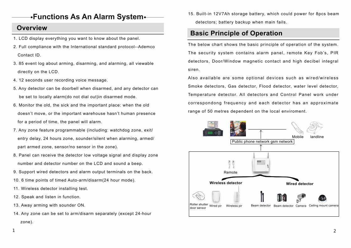
Basic Principle of OperationThe below chart shows the basic principle of operation of the system.
The secur i ty system contains alarm panel , remote Key Fob’s, PIR
detectors, Door/Window magnetic contact and high decibel integral
siren.
A lso ava i lab le are some opt ional dev ices such as wi red/wi re less
Smoke detectors, Gas detector, Flood detector, water level detector,
Temperature detector. Al l detectors and Control Panel work under
cor respondong f requency and each detector has an approx imate
range of 50 metres dependent on the local enviroment.
15. Built- in 12V7Ah storage battery, which could power for 8pcs beam
detectors; battery backup when main fails.
Public phone network gsm networkMobile landline
Remote
Wireless detector Wired detector
Roller shutter door sensor
Wired pir Wireless pir Beam detector Beam detector Camera Ceiling mount camera
4
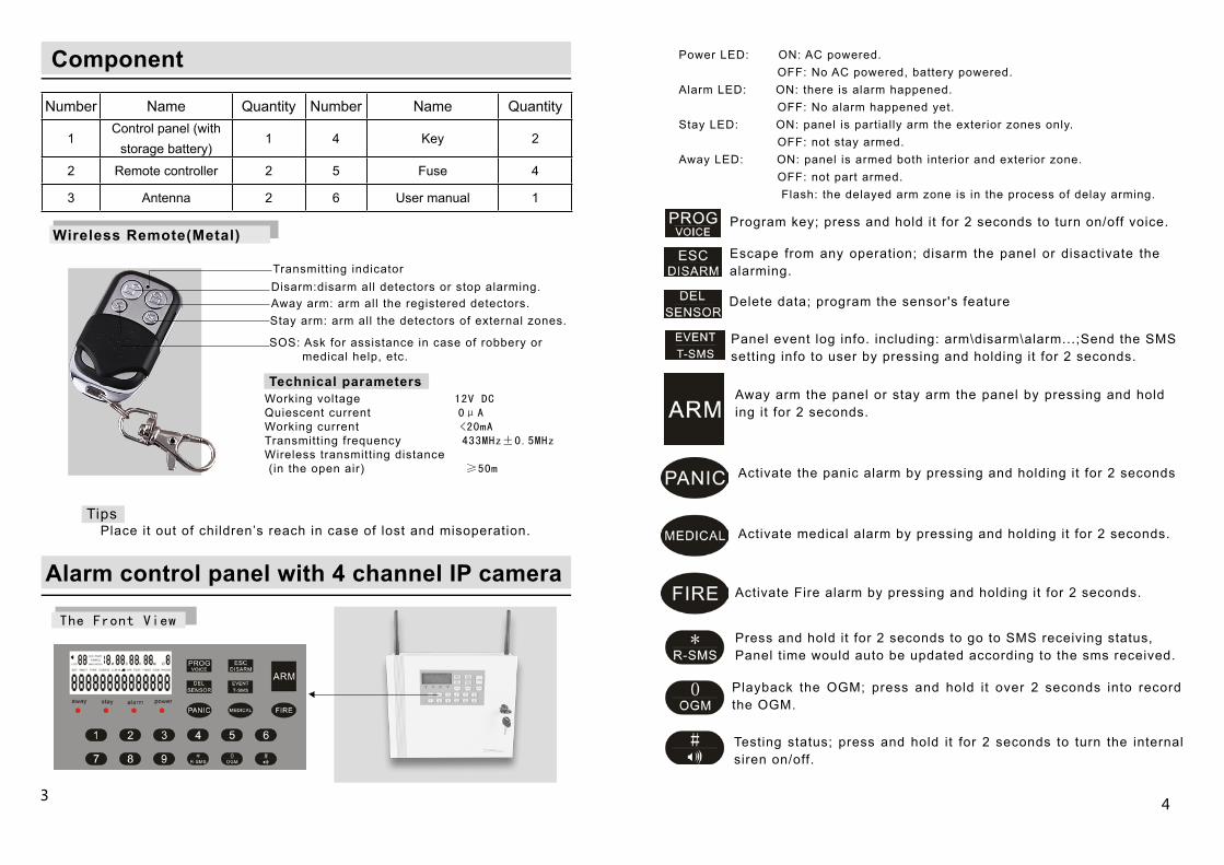
The Front View
Component
Number Name Quantity Number Name Quantity
1Control panel (with
storage battery)1 4 Key 2
2 Remote controller 2 5 Fuse 4
3 Antenna 2 6 User manual 1
Wireless Remote(Metal)
Working voltage 12V DCQuiescent current 0μAWorking current <20mATransmitting frequency 433MHz±0.5MHzWireless transmitting distance (in the open air) ≥50m
Disarm:disarm all detectors or stop alarming.Transmitting indicator
Away arm: arm all the registered detectors.Stay arm: arm all the detectors of external zones.
SOS: Ask for assistance in case of robbery or medical help, etc.
Technical parameters
Tips Place it out of children’s reach in case of lost and misoperation.
3
Alarm control panel with 4 channel IP camera
Power LED: ON: AC powered. OFF: No AC powered, battery powered.Alarm LED: ON: there is alarm happened. OFF: No alarm happened yet.Stay LED: ON: panel is partially arm the exterior zones only. OFF: not stay armed.Away LED: ON: panel is armed both interior and exterior zone. OFF: not part armed. Flash: the delayed arm zone is in the process of delay arming.
Program key; press and hold it for 2 seconds to turn on/off voice.
Escape from any operation; disarm the panel or disactivate the alarming.
Delete data; program the sensor's feature
Panel event log info. including: arm\disarm\alarm...;Send the SMS setting info to user by pressing and holding it for 2 seconds.
Away arm the panel or stay arm the panel by pressing and hold ing it for 2 seconds.
Activate the panic alarm by pressing and holding it for 2 seconds
Activate medical alarm by pressing and holding it for 2 seconds.
Activate Fire alarm by pressing and holding it for 2 seconds.
Press and hold it for 2 seconds to go to SMS receiving status, Panel time would auto be updated according to the sms received.
Playback the OGM; press and hold it over 2 seconds into record the OGM.
Testing status; press and hold it for 2 seconds to turn the internal siren on/off.
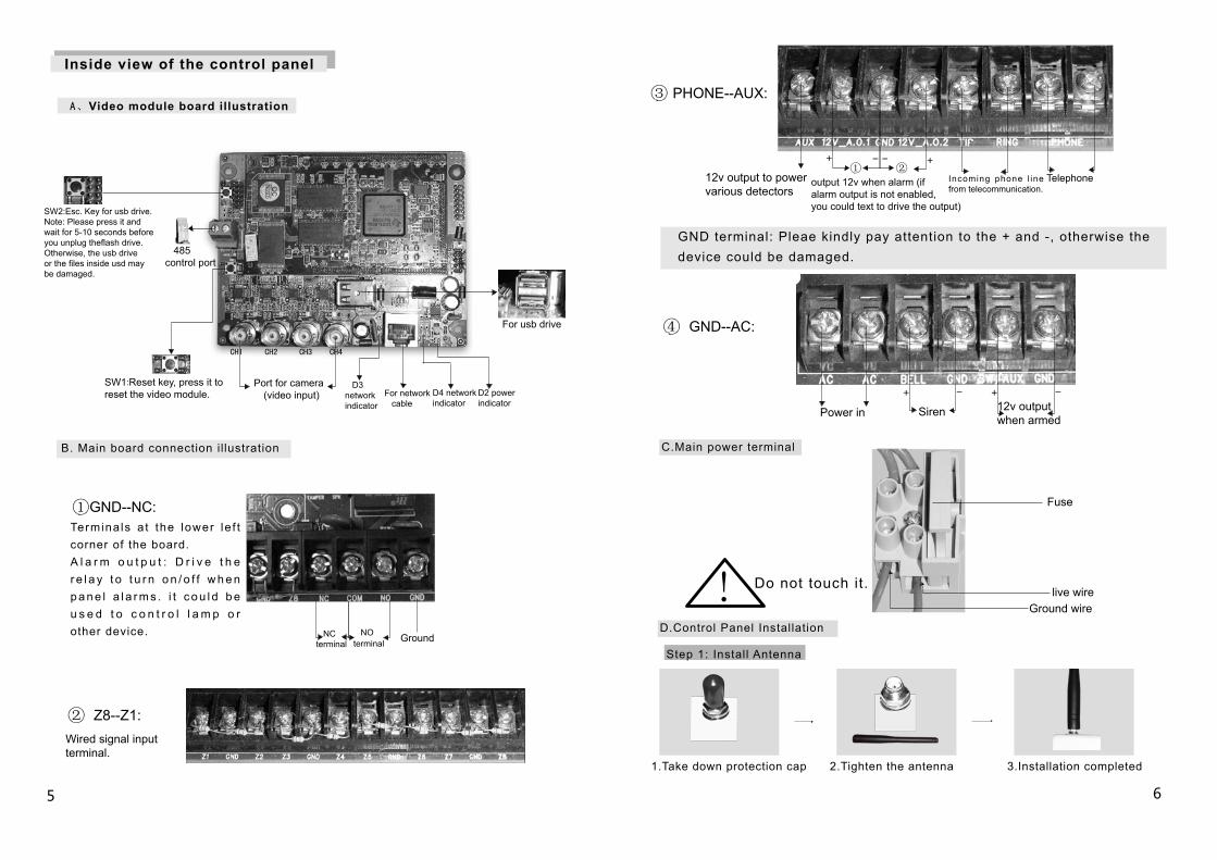
③ PHONE--AUX:
Telephone①
output 12v when alarm (if alarm output is not enabled,you could text to drive the output)
12v output to power various detectors
④ GND--AC:
Power in 12v output when armed
Fuse
live wireDo not touch it.!
Step 1: Install Antenna
②
+ - + -
+ - - +
5 6
1.Take down protection cap 2.Tighten the antenna 3.Installation completed
GND terminal: Pleae kindly pay attention to the + and -, otherwise the device could be damaged.
Port for camera (video input)
485 control port
SW1:Reset key, press it to reset the video module.
SW2:Esc. Key for usb drive.Note: Please press it and wait for 5-10 seconds before you unplug theflash drive. Otherwise, the usb driveor the files inside usd may be damaged.
For usb drive
B. Main board connection il lustration
D2 power indicator
D3 network indicator
D4 network indicator
NC terminal Ground NO
terminal
①GND--NC:
② Z8--Z1:Wired signal input terminal.
Inside view of the control panel
A、Video module board illustration
CHI CH2 CH3 CH4
Termina ls a t the lower le f t corner of the board. A l a r m o u t p u t : D r i v e t h e r e l a y t o t u r n o n / o f f w h e n p a n e l a l a r m s . i t c o u l d b e u s e d t o c o n t r o l l a m p o r other device.
For network cable
Incoming phone l ine from telecommunication.
C.Main power terminal
Siren
Ground wire
D.Control Panel Installation
7
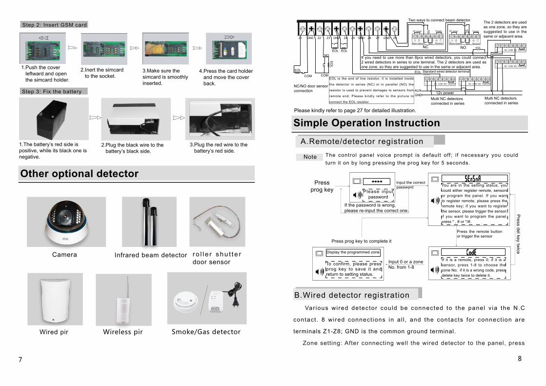
A.Remote/detector registration
Note
8
Please input password
Input the correct password
Press prog key
The control panel voice prompt is default off ; i f necessary you could turn it on by long pressing the prog key for 5 seconds.
You are in the setting status, you could either register remote, sensors or program the panel. If you want to register remote, please press the remote key; if you want to register the sensor, please trigger the sensor; if you want to program the panel, press * , # or */#.
If the password is wrong, please re-input the correct one.
Press the remote button or trigger the sensor
If it is a remote, press 0; if it is a sensor, press 1-8 to choose the zone No; if it is a wrong code, press delete key twice to delete it.
Press prog key to complete it
Press del key tw
ice
Input 0 or a zone No. from 1-8
To confirm, please press prog key to save it and return to setting status.
Display the programmed zone
Var ious wi red detector could be connected to the panel v ia the N.C
contact . 8 wired connect ions in a l l , and the contacts for connect ion are
terminals Z1-Z8; GND is the common ground terminal.
Zone setting: After connecting well the wired detector to the panel, press
Infrared beam detectorCamera r o l l e r shu t t e r door sensor
Wireless pir
2.Plug the black wire to the battery’s black side.
3.Plug the red wire to the battery’s red side.
1.The battery’s red side is positive, while its black one is negative.
1.Push the cover leftward and open the simcard holder.
2.Inert the simcard to the socket.
3.Make sure the simcard is smoothly inserted.
4.Press the card holder and move the cover back.
Smoke/Gas detector
Step 2: Insert GSM card
Step 3: Fix the battery
Other optional detector
Wired pir
Simple Operation Instruction
Z1 GND Z2 Z3 GND Z4 Z5 GND Z6 Z7 GND Z8 ① ② ③ ④ ⑤ ⑥ ⑦ ① ② ③ ④ ⑤ ⑥ ⑦
+ - NC COM NO TAMPER
+ - NC COM NO TAMPER
DC power
EO
L
EOL
alarm alarm
EOL
EOL EOL
COM COM
EO
L
NO
+ - NC COM NO TAMPER + - NC COM NO TAMPER
EOL
AUXGND
EOL
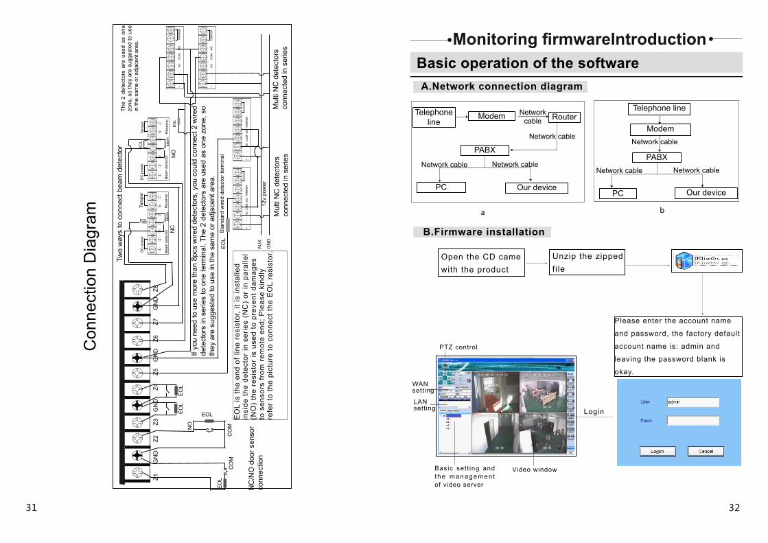
EOL is the end of line resistor, it is installed inside
the detector in series (NC) or in parallel (NO) the
resistor is used to prevent damages to sensors from
remote end; Please kindly refer to the picture to
connect the EOL resistor.
Two ways to connect beam detector The 2 detectors are used as one zone, so they are suggested to use in the same or adjacent area.
NC NO
If you need to use more than 8pcs wired detectors, you could connect 2 wired detectors in series to one terminal. The 2 detectors are used as one zone, so they are suggested to use in the same or adjacent area.
NC/NO door sensor connection
Standard wired detector terminal
Multi NC detectors connected in series
Multi NC detectors connected in series
Tamper DC power Tamper
Beam detector Receiver ReceiverBeam detector
12v power
Please kindly refer to page 27 for detailed illustration.
B.Wired detector registration
Note: This step has no voice instruction; 00 means there is no remote/sensor registered yet.Press 0-8, 1-9
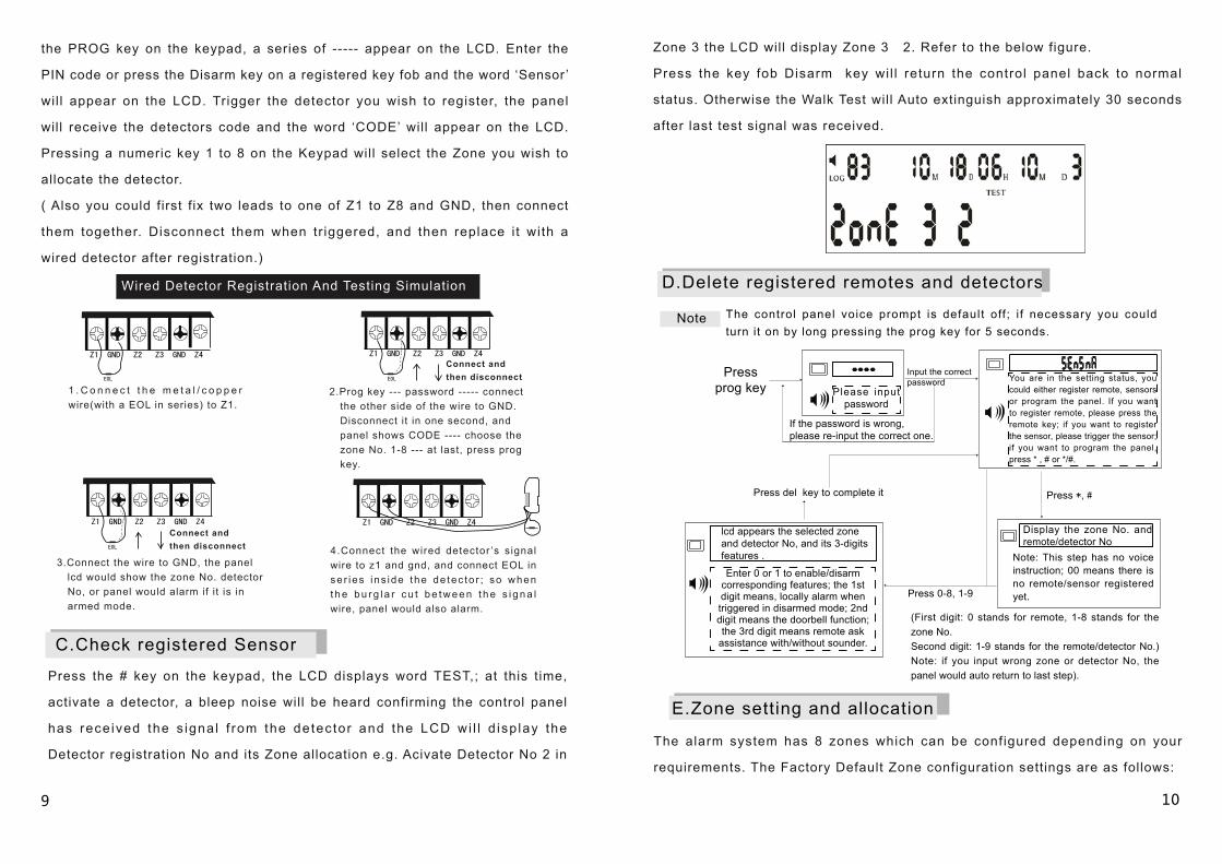
Enter 0 or 1 to enable/disarm corresponding features; the 1st digit means, locally alarm when triggered in disarmed mode; 2nd digit means the doorbell function; the 3rd digit means remote ask
assistance with/without sounder.
Display the zone No. and remote/detector No
9 10
(First digit: 0 stands for remote, 1-8 stands for the zone No. Second digit: 1-9 stands for the remote/detector No.) Note: if you input wrong zone or detector No, the panel would auto return to last step).
Z1 GND Z2 Z3 GND Z4
Wired Detector Registration And Testing Simulation
1 . C o n n e c t t h e m e t a l / c o p p e r wire(with a EOL in series) to Z1.
Connect and then disconnect
Z1 GND Z2 Z3 GND Z4
Z1 GND Z2 Z3 GND Z4 Z1 GND Z2 Z3 GND Z4
the PROG key on the keypad, a series of ----- appear on the LCD. Enter the
PIN code or press the Disarm key on a registered key fob and the word ‘Sensor ’
will appear on the LCD. Trigger the detector you wish to register, the panel
will receive the detectors code and the word ‘CODE’ will appear on the LCD.
Pressing a numeric key 1 to 8 on the Keypad will select the Zone you wish to
allocate the detector.
( Also you could first fix two leads to one of Z1 to Z8 and GND, then connect
them together. Disconnect them when tr iggered, and then replace i t with a
wired detector after registration.)
EOL EOL
EOL
2.Prog key --- password ----- connect the other side of the wire to GND. Disconnect it in one second, and panel shows CODE ---- choose the zone No. 1-8 --- at last, press prog key.
3.Connect the wire to GND, the panel lcd would show the zone No. detector No, or panel would alarm if it is in armed mode.
4.Connect the wired detector ’s signal wire to z1 and gnd, and connect EOL in se r ies i ns ide the de tec to r ; so when t h e b u r g l a r c u t b e t w e e n t h e s i g n a l wire, panel would also alarm.
C.Check registered Sensor
Press the # key on the keypad, the LCD displays word TEST,; at this time,
activate a detector, a bleep noise will be heard confirming the control panel
has rece ived the s igna l f rom the detector and the LCD wi l l d isp lay the
Detector registration No and its Zone allocation e.g. Acivate Detector No 2 in
Zone 3 the LCD will display Zone 3 2. Refer to the below figure.
Press the key fob Disarm key wi l l return the control panel back to normal
status. Otherwise the Walk Test will Auto extinguish approximately 30 seconds
after last test signal was received.
D.Delete registered remotes and detectors
Note The control panel voice prompt is default off ; i f necessary you could turn it on by long pressing the prog key for 5 seconds.
Connect and then disconnect
Please input password
Input the correct password
Press prog key
You are in the setting status, you could either register remote, sensors or program the panel. If you want to register remote, please press the remote key; if you want to register the sensor, please trigger the sensor; if you want to program the panel, press * , # or */#.
If the password is wrong, please re-input the correct one.
Press del key to complete it
lcd appears the selected zone and detector No, and its 3-digits features .
Press *, #
E.Zone setting and allocation
The alarm system has 8 zones which can be configured depending on your
requirements. The Factory Default Zone configuration settings are as follows:
11 12
Press1-6
Press prog key to confirm
and exit
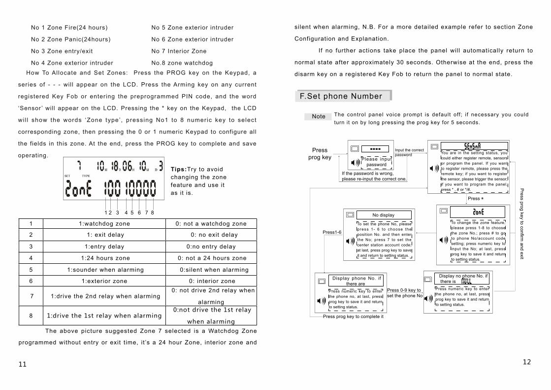
1 1:watchdog zone 0: not a watchdog zone
2 1: exit delay 0: no exit delay
3 1:entry delay 0:no entry delay
4 1:24 hours zone 0: not a 24 hours zone
5 1:sounder when alarming 0:silent when alarming
6 1:exterior zone 0: interior zone
7 1:drive the 2nd relay when alarming 0: not drive 2nd relay when
alarming
8 1:drive the 1st relay when alarming 0:not drive the 1st relay
when alarming The above picture suggested Zone 7 selected is a Watchdog Zone
programmed without entry or exit t ime, it ’s a 24 hour Zone, interior zone and
No 1 Zone Fire(24 hours)
No 2 Zone Panic(24hours)
No 3 Zone entry/exit
No 4 Zone exterior intruder
No 5 Zone exterior intruder
No 6 Zone exterior intruder
No 7 Interior Zone
No.8 zone watchdog
How To Allocate and Set Zones: Press the PROG key on the Keypad, a
series of - - - wil l appear on the LCD. Press the Arming key on any current
registered Key Fob or entering the preprogrammed PIN code, and the word
‘Sensor ’ will appear on the LCD. Pressing the * key on the Keypad, the LCD
wi l l show the words ‘Zone type’ , pressing No1 to 8 numeric key to select
corresponding zone, then pressing the 0 or 1 numeric Keypad to configure all
the fields in this zone. At the end, press the PROG key to complete and save
operating.
1 2 3 4 5 6 7 8
Tips:Try to avoid changing the zone feature and use it as it is.
silent when alarming, N.B. For a more detailed example refer to section Zone
Configuration and Explanation.
If no further actions take place the panel wil l automatically return to
normal state after approximately 30 seconds. Otherwise at the end, press the
disarm key on a registered Key Fob to return the panel to normal state.
F.Set phone Number
Note The control panel voice prompt is default off ; i f necessary you could turn it on by long pressing the prog key for 5 seconds.
Please input password
Input the correct password
Press prog key
You are in the setting status, you could either register remote, sensors or program the panel. If you want to register remote, please press the remote key; if you want to register the sensor, please trigger the sensor; if you want to program the panel, press * , # or */#.
If the password is wrong, please re-input the correct one.
Press *
No display
To set the phone No, please press 1- 6 to choose the position No. and then enter the No; press 7 to set the center station account code; at last, press prog key to save it and return to setting status.
To change the zone feature, please press 1-8 to choose the zone No.; press # to go to phone No/account code setting; press numeric key to input the No; at last, press prog key to save it and return to setting status.
Press prog key to complete it
Display phone No. if there are
Press numeric key to enter the phone no, at last, press prog key to save it and return to setting status.
Display no phone No. if there is
Press numeric key to enter the phone no, at last, press prog key to save it and return to setting status.
Press 0-9 key toset the phone No
13 14
Press#09
Prog
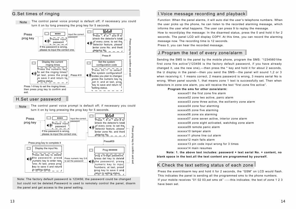
G.Set times of ringing
Note The control panel voice prompt is default off ; i f necessary you could turn it on by long pressing the prog key for 5 seconds.
Please input password
Input the correct password
Press prog key
If the password is wrong, please re-input the correct one.
Press *, # or * and # to check the detector's total of every zone; to set the detector feature, please enter zone No. and then detector No.
Press prog key to confirm
and exit
Press #
Set the system configuration code
Press 00-17 to se lect the system configuration codes you plan to change; press the numeric key to set it; and at last, prog key to save and return to setting status.
Press #10
Display the current ringing times
Press the numeric key to set the ringing times; at last, press the prog to save it and return to setting status.
Press 1-9 key to set the ringing times; then press prog key to confirm and exit.
H.Set user password
Note The control panel voice prompt is default off ; i f necessary you could turn it on by long pressing the prog key for 5 seconds.
Please input password
Input the correct password
Press prog key
If the password is wrong, please re-input the correct one.
Press *, # or * and # to check the detector's total of every zone; to set the detector feature, please enter zone No. and then detector No.
Press del key to delete t h e p a s s w o r d ; p r e s s numeric key to enter new one; At last, press prog key to save it and return to setting status.
prog a 6-digit password, press del key to delete t h e p a s s w o r d ; p r e s s numer i c key to i npu t numbers; at last, press prog key to save it and return to setting status
Press numeric key 0-9 to set the password
Display the input No.
Press prog key to confirm
and exit
Press prog key to complete it
Note: The factory default password is 123456; the password could be changed but could not be deleted.Password is used to remotely control the panel, disarm the panel and get access to the panel setting.
I.Voice message recording and playbackFunction: When the panel alarms, it will auto dial the user ’s telephone numbers. When the user picks up the phone, he can listen to the recorded alarming message, which informs the user what happens. The user can press 9 to replay the message.How to record/play the message: In the disarmed status, press the 0 and hold it for 2 seconds. The panel LCD will display COPY. At this time, you can record the alarming message now. The recording time is 12 seconds.Press 0, you can hear the recorded message.
J.Program the text of every zone/alarmSending the SMS to the panel by the mobile phone, program the SMS: “12345601the f i rst zone f i re act ive”(123456 is the factory default password, i f you have already changed it, use the new one),---then press the * key and hold it for about 2 seconds, the U display in the panel---then you send the SMS---the panel wil l sound 1,2 or 3 when receiving it. 1 means correct, 2 means password is wrong, 3 means serial No is wrong. When panel sounds 1, that means zone 1 text is successfully set. Then when detectors in zone one alarm, you will receive the text “first zone fire active”. Program the sms for other zone/alarm: xxxxxx01 the first zone fire alarm xxxxxx02 zone two active, panic alarm xxxxxx03 zone three active, the exit\entry zone alarm xxxxxx04 zone four alarming xxxxxx05 zone five alarming xxxxxx06 zone six alarming xxxxxx07 zone seven active, interior zone alarm xxxxxx08 zone eight activated, watchdog zone alarm xxxxxx09 remote panic alarm xxxxxx10 tamper alarm xxxxxx11 phone line cut alarm xxxxxx12 main fails alarm xxxxxx13 pin code input wrong for 3 times xxxxxx14 main resumes Note: 1. the above text includes: password + text serial No. + content, no blank space in the text.all the text content are programmed by yourself.
K.Check the text setting status of each zonePress the event/disarm key and hold it for 2 seconds, the “GSM” on LCD would flash. This indicates the panel is sending all the programmed sms to the phone numbers. If your mobile receives “01 02 03,set sms ok” -----this indicates: the text of zone 1 2 3 have been set.
15 16
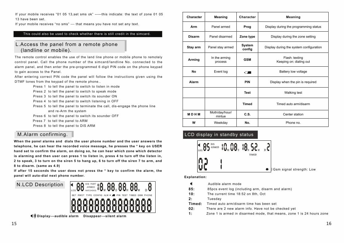
Character Meaning Character Meaning
Arm Panel armed Prog Display during the programming status
Disarm Panel disarmed Zone type Display during the zone setting
Stay arm Panel stay armed System config Display during the system configuration
Arming In the arming process GSM Flash: texting
Keeping on: dialing out
No Event log Battery low voltage
Alarm PIN Display when the pin is required
Test Walking test
Timed Timed auto arm/disarm
M D H M Moth/day/hour/mintue C.S. Center station
W Weekday No. Phone no.
LCD display in standby status
If your mobile receives “01 05 13,set sms ok” -----this indicate: the text of zone 01 05 13 have been set. If your mobile receives “no sms” --- that means you have not set any text.
This could also be used to check whether there is stil l credit in the simcard.
L.Access the panel from a remote phone (landline or mobile). The remote control enables the use of the land line phone or mobile phone to remotely control panel. Cal l the phone number of the simcard/ landl ine No. connected to the alarm panel, and then enter the pre-programmed 6 digit PIN code on the phone keypad to gain access to the Panel.After entering correct PIN code the panel wil l fol low the instructions given using the DTMF tones from the keypad of the remote phone.. Press 1 to tell the panel to switch to listen in mode Press 2 to tell the panel to switch to speak mode Press 3 to tell the panel to switch its sounder ON Press 4 to tell the panel to switch listening in OFF Press 5 to tell the panel to terminate the call, dis-engage the phone line and re-Arm the system Press 6 to tell the panel to switch its sounder OFF Press 7 to tell the panel to ARM Press 8 to tell the panel to DIS ARM
M.Alarm confirming.When the panel alarms and dials the user phone number and the user answers the telephone, he can hear the recorded voice message, he presses the * key on USER hand set to confirm the alarm, on doing so, he can hear which zone which detector is alarming and then user can press 1 to listen in, press 4 to turn off the listen in, 2 to speak, 3 to turn on the siren 5 to hang up, 6 to turn off the siren 7 to arm, and 8 to disarm. (same as 4.9)If after 15 seconds the user does not press the * key to confirm the alarm, the panel will auto-dial next phone number.
N.LCD Description
Display---audible alarm Disappear---silent alarm
}Gsm signal strength: Low
Explanation:
Audible alarm mode85: 85pcs event log (including arm, disarm and alarm)10: The current time 18:52 on 8th, Oct2: TuesdayTimed: Timed auto arm/disarm time has been set02: There are 2 new alarm info. Have not be checked yet1: Zone 1 is armed in disarmed mode, that means, zone 1 is 24 hours zone
17 18
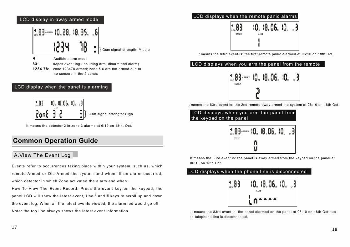
LCD display in away armed mode
}Gsm signal strength: Middle
Audible alarm mode83: 83pcs event log (including arm, disarm and alarm)1234 78: zone 123478 armed; zone 5.6 are not armed due to no sensors in the 2 zones
LCD display when the panel is alarming
}Gsm signal strength: High
It means the detector 2 in zone 3 alarms at 6:19 on 18th, Oct.
Common Operation Guide
A.View The Event Log
Events refer to occurrences taking place within your system, such as, which
remote Armed or Dis-Armed the system and when. I f an a larm occurred,
which detector in which Zone activated the alarm and when.
How To View The Event Record: Press the event key on the keypad, the
panel LCD will show the latest event, Use * and # keys to scroll up and down
the event log. When all the latest events viewed, the alarm led would go off.
Note: the top l ine always shows the latest event information.
LCD displays when the remote panic alarms
It means the 83rd event is: the first remote panic alarmed at 06:10 on 18th Oct.
LCD displays when you arm the panel from the remote
It means the 83rd event is: the 2nd remote away armed the system at 06:10 on 18th Oct.
LCD displays when you arm the panel from the keypad on the panel
It means the 83rd event is: the panel is away armed from the keypad on the panel at 06:10 on 18th Oct.
LCD displays when the phone line is disconnected
It means the 83rd event is: the panel alarmed on the panel at 06:10 on 18th Oct due to telephone line is disconnected.
19 20
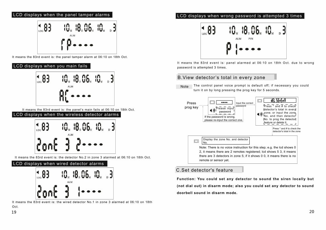
LCD displays when the panel tamper alarms
It means the 83rd event is: the panel tamper alarm at 06:10 on 18th Oct.
LCD displays when you main fails
It means the 83rd event is: the panel’s main fails at 06:10 on 18th Oct.
LCD displays when the wireless detector alarms
It means the 83rd event is: the detector No.2 in zone 3 alarmed at 06:10 on 18th Oct.
LCD displays when wired detector alarms
It means the 83rd event is: the wired detector No.1 in zone 3 alarmed at 06:10 on 18th Oct.
LCD displays when wrong password is attempted 3 times
I t means the 83rd event is : pane l a larmed a t 06:10 on 18th Oct . due to wrong password is attempted 3 times.
B.View detector ’s total in every zone
Note The control panel voice prompt is default off ; i f necessary you could turn it on by long pressing the prog key for 5 seconds.
Please input password
Input the correct password
Press prog key
If the password is wrong, please re-input the correct one.
Press * and # to check detector’s total in every zone; or input the zone No. and then detector No. to prog the detector feature or delete it.
Press * and # to check the detector's total in the zone
Display the zone No. and detector No.
Note: There is no voice instruction for this step; e.g. the lcd shows 0 2, it means there are 2 remotes registered; lcd shows 5 3, it means there are 3 detectors in zone 5; if it shows 0 0, it means there is no remote or sensor yet.
C.Set detector's feature
Function: You could set any detector to sound the siren locally but
(not dial out) in disarm mode; also you could set any detector to sound
doorbell sound in disarm mode.
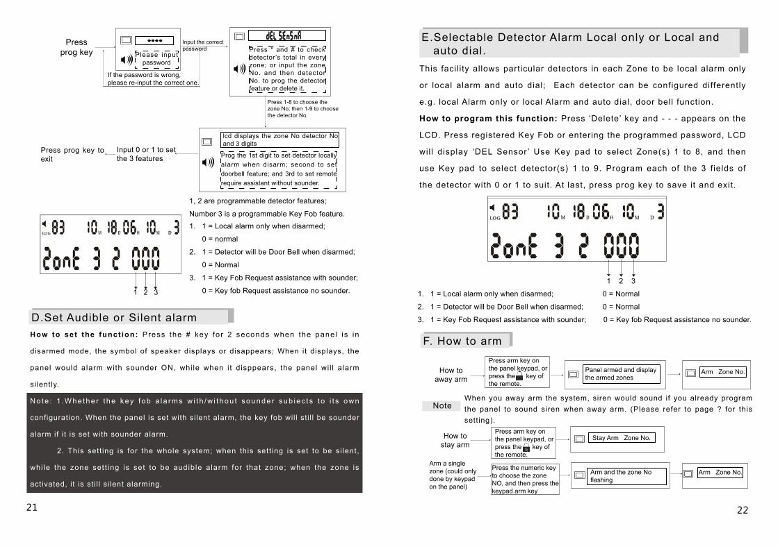
Press arm key on the panel keypad, or press the key of the remote.
When you away arm the system, siren would sound if you already program the panel to sound siren when away arm. (Please refer to page ? for this setting).
Press arm key on the panel keypad, or press the key of the remote.
2221
1, 2 are programmable detector features;
Number 3 is a programmable Key Fob feature.1. 1 = Local alarm only when disarmed;
0 = normal
2. 1 = Detector will be Door Bell when disarmed;
0 = Normal
3. 1 = Key Fob Request assistance with sounder;
0 = Key fob Request assistance no sounder.
Please input password
Input the correct password
Press prog key
If the password is wrong, please re-input the correct one.
Press * and # to check detector’s total in every zone; or input the zone No. and then detector No. to prog the detector feature or delete it.
Press 1-8 to choose the zone No; then 1-9 to choose the detector No.
lcd displays the zone No detector No and 3 digits
Prog the 1st digit to set detector locally alarm when disarm; second to set doorbell feature; and 3rd to set remote require assistant without sounder.
Input 0 or 1 to set the 3 features
Press prog key to exit
1 2 3
D.Set Audible or Silent alarmHow to set the funct ion: Press the # key fo r 2 seconds when the pane l i s in
disarmed mode, the symbol of speaker displays or disappears; When it displays, the
panel would alarm with sounder ON, whi le when i t disppears, the panel wi l l alarm
silently.
No te : 1 .Whe the r t he key fob a la rms w i th /w i t hou t sounde r sub iec t s t o i t s own
configuration. When the panel is set with silent alarm, the key fob wil l sti l l be sounder
alarm if it is set with sounder alarm.
2. This sett ing is for the whole system; when this sett ing is set to be si lent,
whi le the zone set t ing is set to be audible alarm for that zone; when the zone is
activated, it is sti l l si lent alarming.
E.Selectable Detector Alarm Local only or Local and auto dial.This facil i ty allows particular detectors in each Zone to be local alarm only
or local alarm and auto dial; Each detector can be configured differently
e.g. local Alarm only or local Alarm and auto dial, door bell function.
How to program this function: Press ‘Delete’ key and - - - appears on the
LCD. Press registered Key Fob or entering the programmed password, LCD
wil l display ‘DEL Sensor ’ Use Key pad to select Zone(s) 1 to 8, and then
use Key pad to select detector(s) 1 to 9. Program each of the 3 f ields of
the detector with 0 or 1 to suit. At last, press prog key to save it and exit.
F. How to arm
1 2 3
1. 1 = Local alarm only when disarmed; 0 = Normal
2. 1 = Detector will be Door Bell when disarmed; 0 = Normal
3. 1 = Key Fob Request assistance with sounder; 0 = Key fob Request assistance no sounder.
How to away arm
Panel armed and display the armed zones
Arm Zone No.
Note
How to stay arm
Arm a single zone (could only done by keypad on the panel)
Stay Arm Zone No.
Press the numeric key to choose the zone NO, and then press the keypad arm key
Arm and the zone No flashing
Arm Zone No.
You are in the setting status, you cou ld e i ther reg is ter remote, sensors or program the panel . I f you want to register remote, please press the remote key; if you want to register the sensor, please trigger the sensor; if you want to program the panel, press * , # or */#.
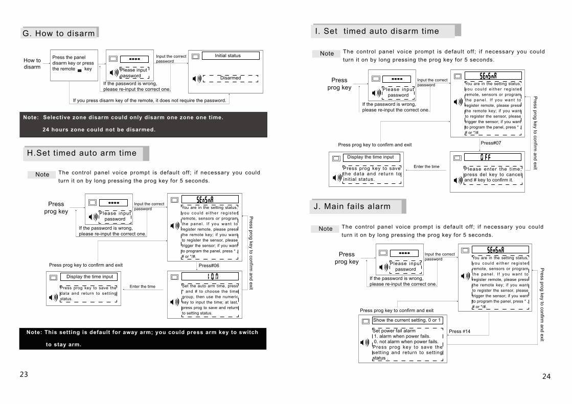
Press the panel disarm key or press the remote key
2423
Please input password Disarmed
Initial status
Press#06
G. How to disarm
How to disarm
If the password is wrong, please re-input the correct one.
Input the correct password
If you press disarm key of the remote, it does not require the password.
Note: Selective zone disarm could only disarm one zone one time.
24 hours zone could not be disarmed.
H.Set timed auto arm time
Note The control panel voice prompt is default off ; i f necessary you could turn it on by long pressing the prog key for 5 seconds.
Please input password
Input the correct password
Press prog key
If the password is wrong, please re-input the correct one.
Set the auto arm time, press * and # to choose the time group, then use the numeric key to input the time; at last, press prog to save and return to setting status.
Display the time input
Enter the timePress prog key to save the data and return to sett ing status.
Press prog key to confirm and exit
Press prog key to confirm
and exit
Note: This setting is default for away arm; you could press arm key to switch
to stay arm.
I. Set timed auto disarm time
Press#07
Please enter the t ime; press del key to cancel and # key to confirm it.
Press prog key to save the data and return to init ial status.
Press #14Set power fail alarm 1. alarm when power fails. 0. not alarm when power fails.Press prog key to save the setting and return to setting status .
You are in the setting status, you cou ld e i ther reg is ter remote, sensors or program the panel . I f you want to register remote, please press the remote key; if you want to register the sensor, please trigger the sensor; if you want to program the panel, press * , # or */#.
Please input password
Input the correct password
Press prog key
If the password is wrong, please re-input the correct one.
Press prog key to confirm
and exit
Press prog key to confirm and exit
Enter the time
Display the time input
Note The control panel voice prompt is default off ; i f necessary you could turn it on by long pressing the prog key for 5 seconds.
J. Main fails alarm
Note The control panel voice prompt is default off ; i f necessary you could turn it on by long pressing the prog key for 5 seconds.
You are in the setting status, you cou ld e i ther reg is ter remote, sensors or program the panel . I f you want to register remote, please press the remote key; if you want to register the sensor, please trigger the sensor; if you want to program the panel, press * , # or */#.
Please input password
Input the correct password
Press prog key
If the password is wrong, please re-input the correct one.
Press prog key to confirm
and exit
Press prog key to confirm and exit
Show the current setting, 0 or 1
25 26
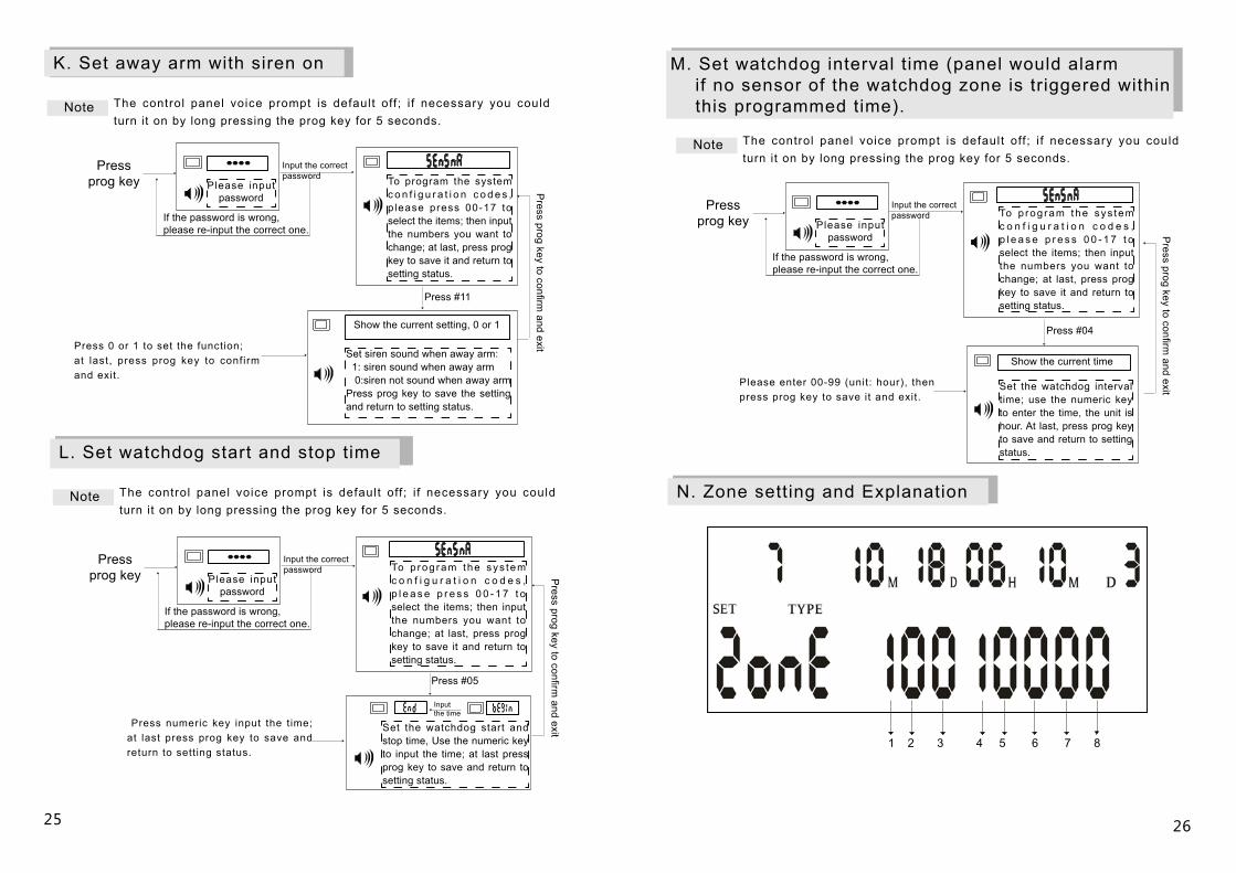
Press #11
To program the system c o n f i g u r a t i o n c o d e s , p lease press 00-17 to select the items; then input the numbers you want to change; at last, press prog key to save it and return to setting status.
Press 0 or 1 to set the function; at last, press prog key to confirm and exit.
Set siren sound when away arm: 1: siren sound when away arm 0:siren not sound when away armPress prog key to save the setting and return to setting status.
Press #05
Set the watchdog start and stop time, Use the numeric key to input the time; at last press prog key to save and return to setting status.
Press #04
Set the watchdog interval time; use the numeric key to enter the time, the unit is hour. At last, press prog key to save and return to setting status.
K. Set away arm with siren on
Note The control panel voice prompt is default off ; i f necessary you could turn it on by long pressing the prog key for 5 seconds.
Please input password
Input the correct password
Press prog key
If the password is wrong, please re-input the correct one.
Show the current setting, 0 or 1
Press prog key to confirm
and exit
L. Set watchdog start and stop time
Note The control panel voice prompt is default off ; i f necessary you could turn it on by long pressing the prog key for 5 seconds.
Please input password
Input the correct password
Press prog key
If the password is wrong, please re-input the correct one.
To p rog ram the sys tem c o n f i g u r a t i o n c o d e s , p l e a s e p r e s s 0 0 - 1 7 t o select the items; then input the numbers you want to change; at last, press prog key to save it and return to setting status.
Input the time
Press numeric key input the time; at last press prog key to save and return to setting status.
M. Set watchdog interval time (panel would alarm if no sensor of the watchdog zone is triggered within this programmed time).
Note The control panel voice prompt is default off ; i f necessary you could turn it on by long pressing the prog key for 5 seconds.
Press prog key to confirm
and exit
Please input password
Input the correct password
Press prog key
If the password is wrong, please re-input the correct one.
To p rog ram the sys tem c o n f i g u r a t i o n c o d e s , p l e a s e p r e s s 0 0 - 1 7 t o select the items; then input the numbers you want to change; at last, press prog key to save it and return to setting status.
Press prog key to confirm
and exit
Show the current time
Please enter 00-99 (unit: hour), then press prog key to save it and exit.
N. Zone setting and Explanation
1 2 3 4 5 6 7 8
27 28
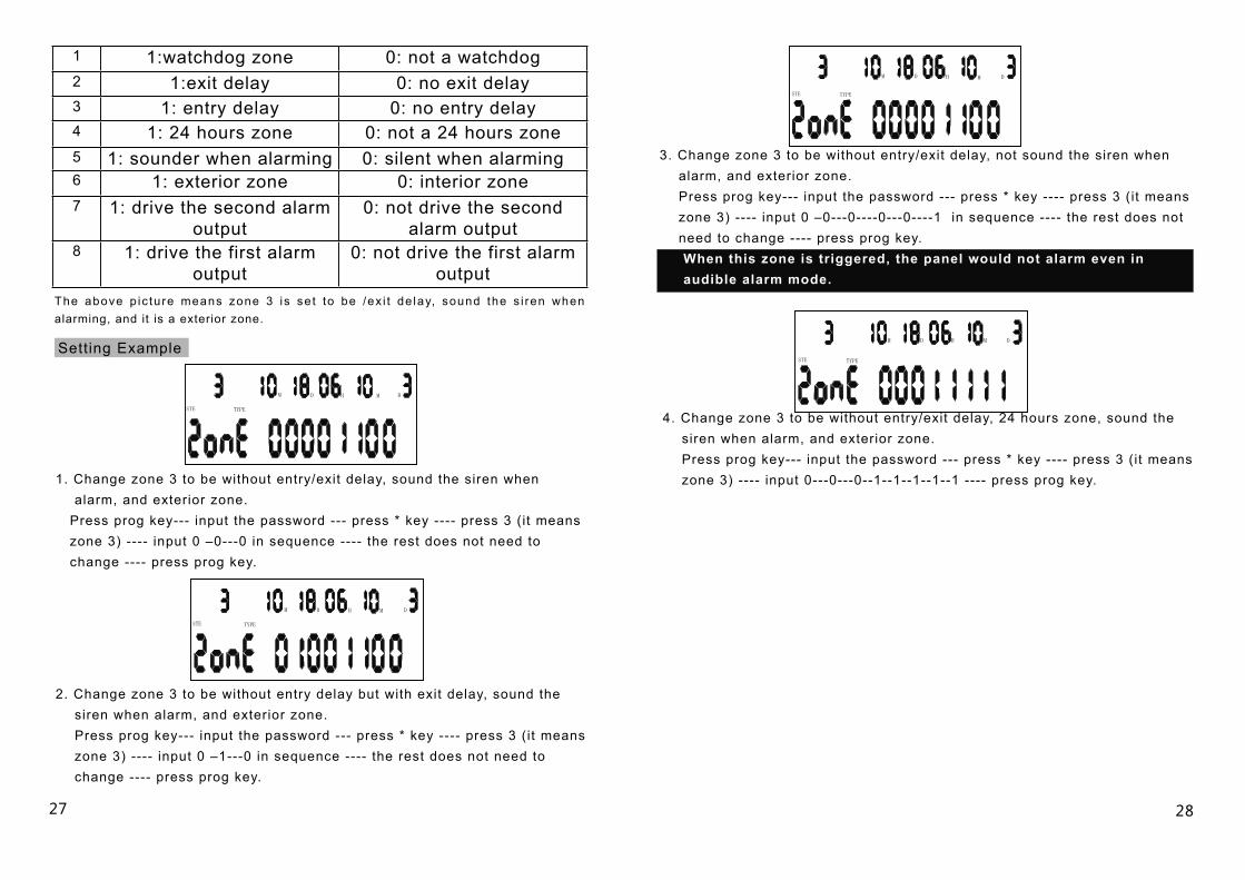
1 1:watchdog zone 0: not a watchdog 2 1:exit delay 0: no exit delay3 1: entry delay 0: no entry delay4 1: 24 hours zone 0: not a 24 hours zone5 1: sounder when alarming 0: silent when alarming6 1: exterior zone 0: interior zone7 1: drive the second alarm
output0: not drive the second
alarm output8 1: drive the first alarm
output0: not drive the first alarm
output
Setting Example
M D H M D
STE TYPE
M D H M D
STE TYPE
STE TYPE
M D H M D
The above p ic ture means zone 3 is se t to be /ex i t de lay, sound the s i ren when alarming, and it is a exterior zone.
1. Change zone 3 to be without entry/exit delay, sound the siren when alarm, and exterior zone. Press prog key--- input the password --- press * key ---- press 3 (it means zone 3) ---- input 0 –0---0 in sequence ---- the rest does not need to change ---- press prog key.
2. Change zone 3 to be without entry delay but with exit delay, sound the siren when alarm, and exterior zone. Press prog key--- input the password --- press * key ---- press 3 (it means zone 3) ---- input 0 –1---0 in sequence ---- the rest does not need to change ---- press prog key.
3. Change zone 3 to be without entry/exit delay, not sound the siren when alarm, and exterior zone. Press prog key--- input the password --- press * key ---- press 3 (it means zone 3) ---- input 0 –0---0----0---0----1 in sequence ---- the rest does not need to change ---- press prog key. When this zone is triggered, the panel would not alarm even in audible alarm mode.
STE TYPE
M D H M D
4. Change zone 3 to be without entry/exit delay, 24 hours zone, sound the siren when alarm, and exterior zone. Press prog key--- input the password --- press * key ---- press 3 (it means zone 3) ---- input 0---0---0--1--1--1--1--1 ---- press prog key.

3029
18 Sensor low voltage with beep 0: no 1:Yes default 1
19 Main fails alarm with sounder0: no 1:Yes default 1 (Effective when #14 is turned on)
20 Auto text and dial when alarm 0: no 1:yes default 1
21 Not available
22 Set the year Default is 10, year 2010
23 Not available
24 Not available
25 Not available
26 Not available
27 Sound the keypad tone 0: no 1:yes default: 1
28 Dial in to remote control 0: no 1:yes default 1
29Dial from simcard when landline is connected
0: no 1:yes default 0
30Reset the video module parameter setting
Press 7 to reset
01 Exit delay time. The init ialization value is 06 = 30 seconds arm delay
02 Entry delay time The init ialization value is 04 = 20 seconds alarm delay
03 Sounder run time The init ialization value is 06 = 120 seconds
04 Watchdog interval t ime Factory default value is 12hours
05 Watchdog start and stop time Default setting is from 8:00 to 20:00
06 Set time to Arm. Press * or #Select the time poitns( 6 time points in all) enter the time desired. To cancel this set, press Delete key.
07 Set t ime to disarm
Press * or #, select the time point ( 6
t ime points in all) enter the time desired.
To cancel this set, press Delete key. 08 Not available
09 Change the password 6 digit code Cancel the password, use
the Delete key
10 Set numbers of ringing
in times
Default value is 8 times, min.
6 and max.9
11 Arming with sounder ON/OFF 0: no sounder when arming 1: sounder when arming default 0
12 Speak 0: No 1: YES default 0
13 Listen to dial out DTMF 0 = NO: 1 = YES. Default: 0
14 Mains Fail alarm 0 = NO ; 1 = YES. Default 0
15 Away arm delay with beep 0. no 1:yes default 0
16 Phone line cut alarm 0: NO 1: YES default 0
17 Not available
Quick Reference
31 32
Con
nect
ion
Dia
gram
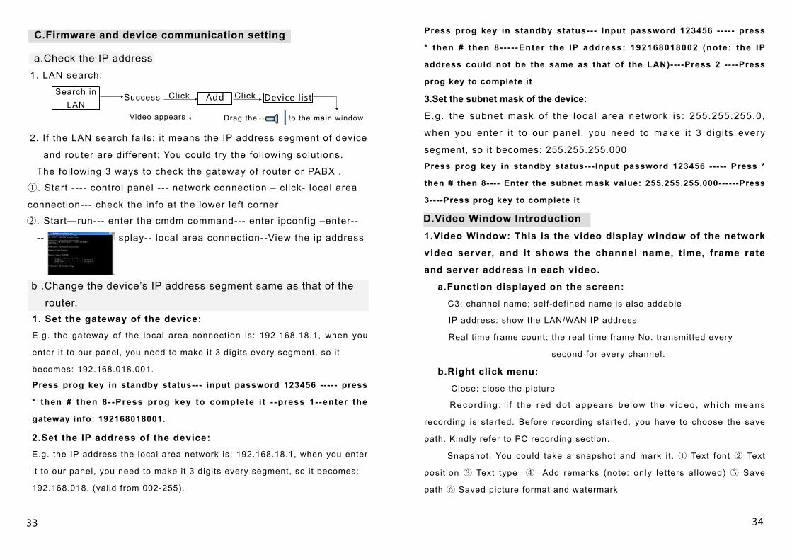
A.Network connection diagram
Telephone line
Modem Router
PC Our device
PABX
Network cable
Open the CD came with the product
Please enter the account name
and password, the factory default
account name is: admin and
leaving the password blank is
okay.
Login
Video windowBasic set t ing and t h e m a n a g e m e n t of video server
Modem
PC Our device
PABX
a b
Monitoring firmwareIntroductionBasic operation of the software
Network cable
Network cable
Network cable
Telephone line
Network cable
Network cable Network cable
B.Firmware installation
Unzip the zipped file
PTZ control
WAN setting
LAN setting
The
2 de
tect
ors
are
used
as
one
zone
, so
they
are
sug
gest
ed to
use
in
the
sam
e or
adj
acen
t are
a.
Z1
G
ND
Z
2
Z3
G
ND
Z
4
Z5
G
ND
Z
6
Z7
G
ND
Z8
①
②
③
④
⑤
⑥
⑦
①
②
③
④
⑤
⑥
⑦
+
-
NC
C
OM
N
O
T
AM
PE
R
+
-
NC
C
OM
N
O
T
AM
PE
R
DC
pow
er
EOL
EO
L
alar
mal
arm
EO
L
EO
LE
OL
CO
MC
OM
EOL
NO
+
-
N
C C
OM
NO
TA
MP
ER
+
-
N
C C
OM
NO
TA
MP
ER
EO
L
AU
X
GN
D
EO
L
EO
L is
the
end
of li
ne r
esis
tor,
it is
inst
alle
d in
side
the
dete
ctor
in s
erie
s (N
C)
or in
par
alle
l (N
O)
the
resi
stor
is u
sed
to p
reve
nt d
amag
es
to s
enso
rs fr
om r
emot
e en
d; P
leas
e ki
ndly
re
fer
to th
e pi
ctur
e to
con
nect
the
EO
L re
sist
or.
Two
way
s to
con
nect
bea
m d
etec
tor
NC
NO
If yo
u ne
ed to
use
mor
e th
an 8
pcs
wire
d de
tect
ors,
you
cou
ld c
onne
ct 2
wire
d de
tect
ors
in s
erie
s to
one
term
inal
. The
2 d
etec
tors
are
use
d as
one
zon
e, s
o th
ey a
re s
ugge
sted
to u
se in
the
sam
e or
adj
acen
t are
a.
NC
/NO
doo
r sen
sor
conn
ectio
n
Sta
ndar
d w
ired
dete
ctor
term
inal
Mul
ti N
C d
etec
tors
co
nnec
ted
in s
erie
sM
ulti
NC
det
ecto
rs
conn
ecte
d in
ser
ies
Tam
per
DC
pow
erTa
mpe
r
Bea
m d
etec
tor
Rec
eive
rR
ecei
ver
Bea
m d
etec
tor
12v
pow
er
②. Start—run--- enter the cmdm command--- enter ipconfig –enter--
-- splay-- local area connection--View the ip address
33 34
1. LAN search:
Search in LAN
Success Add Device list
Drag the to the main window
a.Check the IP address
The following 3 ways to check the gateway of router or PABX .
C.Firmware and device communication setting
Click Click
Video appears
2. If the LAN search fails: it means the IP address segment of device
and router are different; You could try the following solutions.
①. Start ---- control panel --- network connection – click- local area
connection--- check the info at the lower left corner
b .Change the device’s IP address segment same as that of the router.1. Set the gateway of the device: E.g. the gateway of the local area connection is: 192.168.18.1, when you
enter it to our panel, you need to make it 3 digits every segment, so it
becomes: 192.168.018.001.
Press prog key in standby status--- input password 123456 ----- press
* then # then 8- -Press prog key to complete i t - -press 1- -enter the
gateway info: 192168018001.
2.Set the IP address of the device: E.g. the IP address the local area network is: 192.168.18.1, when you enter
i t to our panel, you need to make it 3 digits every segment, so it becomes:
192.168.018. (valid from 002-255).
Press prog key in standby status--- Input password 123456 ----- press
* then # then 8- - - - -Enter the IP address: 192168018002 (note: the IP
address could not be the same as that of the LAN)----Press 2 ----Press
prog key to complete it
3.Set the subnet mask of the device:
E.g. the subnet mask of the local area network is: 255.255.255.0,
when you enter i t to our panel, you need to make i t 3 digi ts every
segment, so it becomes: 255.255.255.000
Press prog key in standby status---Input password 123456 ----- Press *
then # then 8---- Enter the subnet mask value: 255.255.255.000------Press
3----Press prog key to complete it
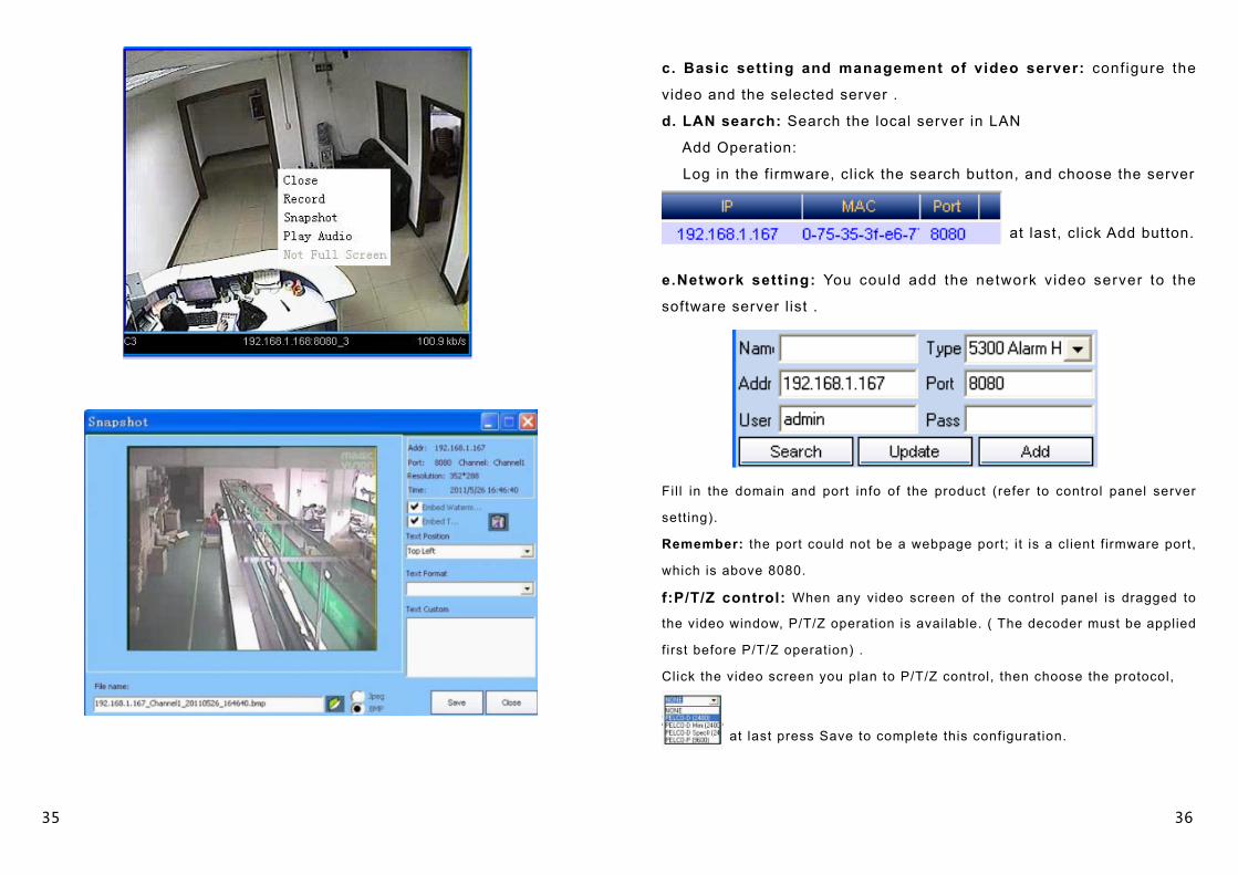
D.Video Window Introduction1.Video Window: This is the video display window of the network
video server, and it shows the channel name, t ime, frame rate
and server address in each video.
a.Function displayed on the screen:
C3: channel name; self-defined name is also addable
IP address: show the LAN/WAN IP address
Real t ime frame count: the real t ime frame No. transmitted every
second for every channel.
b.Right click menu:
Close: close the picture
Reco rd ing : i f t he red do t appea rs be low the v ideo , wh i ch means
recording is started. Before recording started, you have to choose the save
path. Kindly refer to PC recording section.
Snapshot: You could take a snapshot and mark it. ① Text font ② Text
posit ion ③ Text type ④ Add remarks (note: only letters al lowed) ⑤ Save
path ⑥ Saved picture format and watermark
35 36
c. Basic setting and management of video server: conf igure the
video and the selected server .
d. LAN search: Search the local server in LAN
Add Operation:
Log in the firmware, click the search button, and choose the server
at last, cl ick Add button.
e.Network setting: You could add the network video server to the
software server l ist .
Fil l in the domain and port info of the product (refer to control panel server
setting).
Remember: the port could not be a webpage port; it is a client f irmware port,
which is above 8080.
f:P/T/Z control: When any video screen of the control panel is dragged to
the video window, P/T/Z operation is available. ( The decoder must be applied
first before P/T/Z operation) .
Click the video screen you plan to P/T/Z control, then choose the protocol,
at last press Save to complete this configuration.
37 38
Pan, tilt and zoom in/out.
Focus。 Zoom in/out。 Auto cruise。
Color adjustment, Restore factory default。
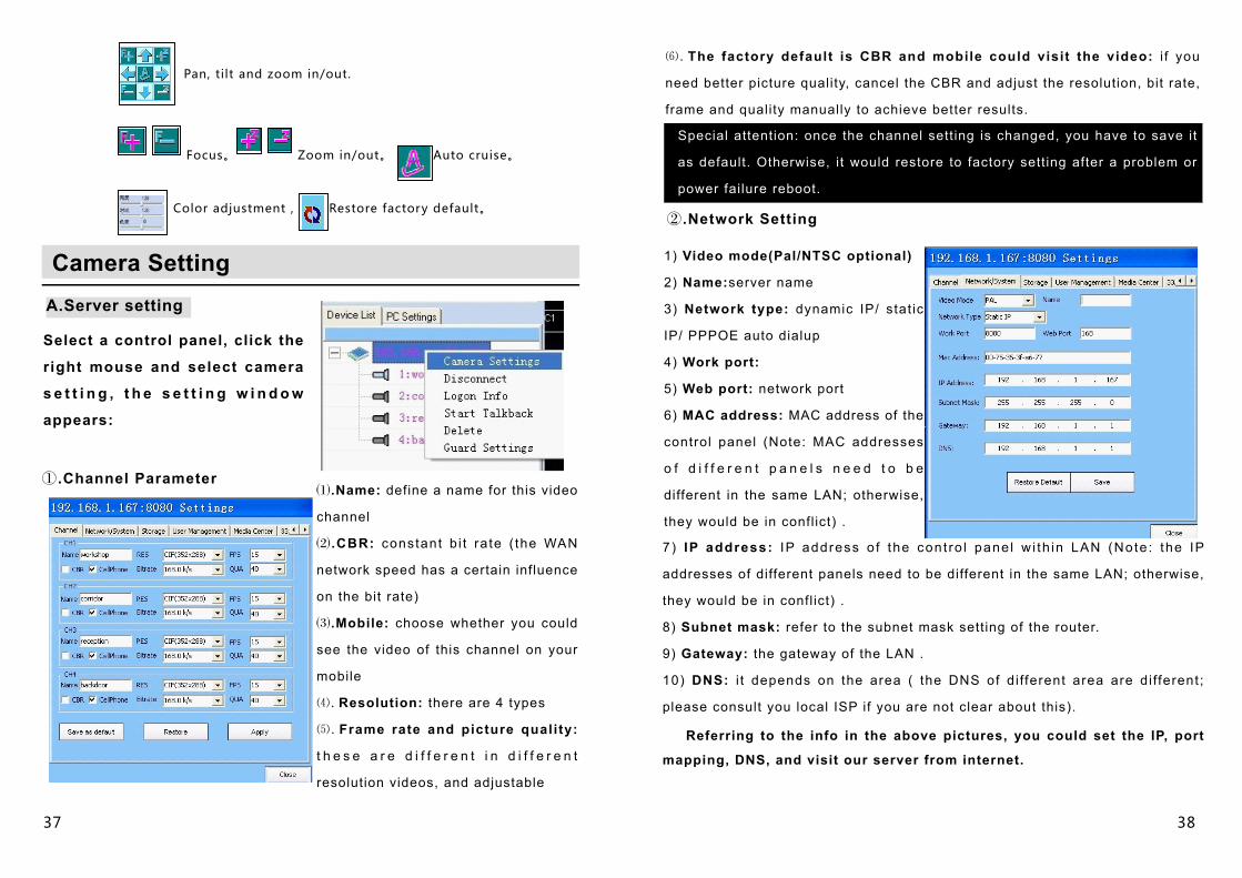
Camera SettingA.Server setting
Select a control panel, click the
right mouse and select camera
s e t t i n g , t h e s e t t i n g w i n d o w
appears:
①.Channel Parameter⑴.Name: define a name for this video
channel
⑵ .CBR: constant b i t ra te ( the WAN
network speed has a certain influence
on the bit rate)
⑶.Mobile: choose whether you could
see the video of this channel on your
mobile
⑷.Resolution: there are 4 types
⑸.Frame rate and picture quality:
t h e s e a r e d i f f e r e n t i n d i f f e r e n t
resolution videos, and adjustable
⑹.The factory default is CBR and mobile could visit the video: i f you
need better picture quality, cancel the CBR and adjust the resolution, bit rate,
frame and quality manually to achieve better results.
Special attention: once the channel setting is changed, you have to save it
as default. Otherwise, it would restore to factory setting after a problem or
power failure reboot.
②.Network Setting
1) Video mode(Pal/NTSC optional)
2) Name:server name
3) Network type: dynamic IP/ stat ic
IP/ PPPOE auto dialup
4) Work port:
5) Web port: network port
6) MAC address: MAC address of the
control panel (Note: MAC addresses
o f d i f f e r e n t p a n e l s n e e d t o b e
different in the same LAN; otherwise,
they would be in conflict) .
7 ) IP address: IP address o f the cont ro l pane l w i th in LAN (Note : the IP
addresses of different panels need to be different in the same LAN; otherwise,
they would be in conflict) .
8) Subnet mask: refer to the subnet mask setting of the router.
9) Gateway: the gateway of the LAN .
10) DNS: i t depends on the area ( the DNS of di fferent area are di fferent;
please consult you local ISP if you are not clear about this).
Referring to the info in the above pictures, you could set the IP, port
mapping, DNS, and visit our server from internet.
39 40
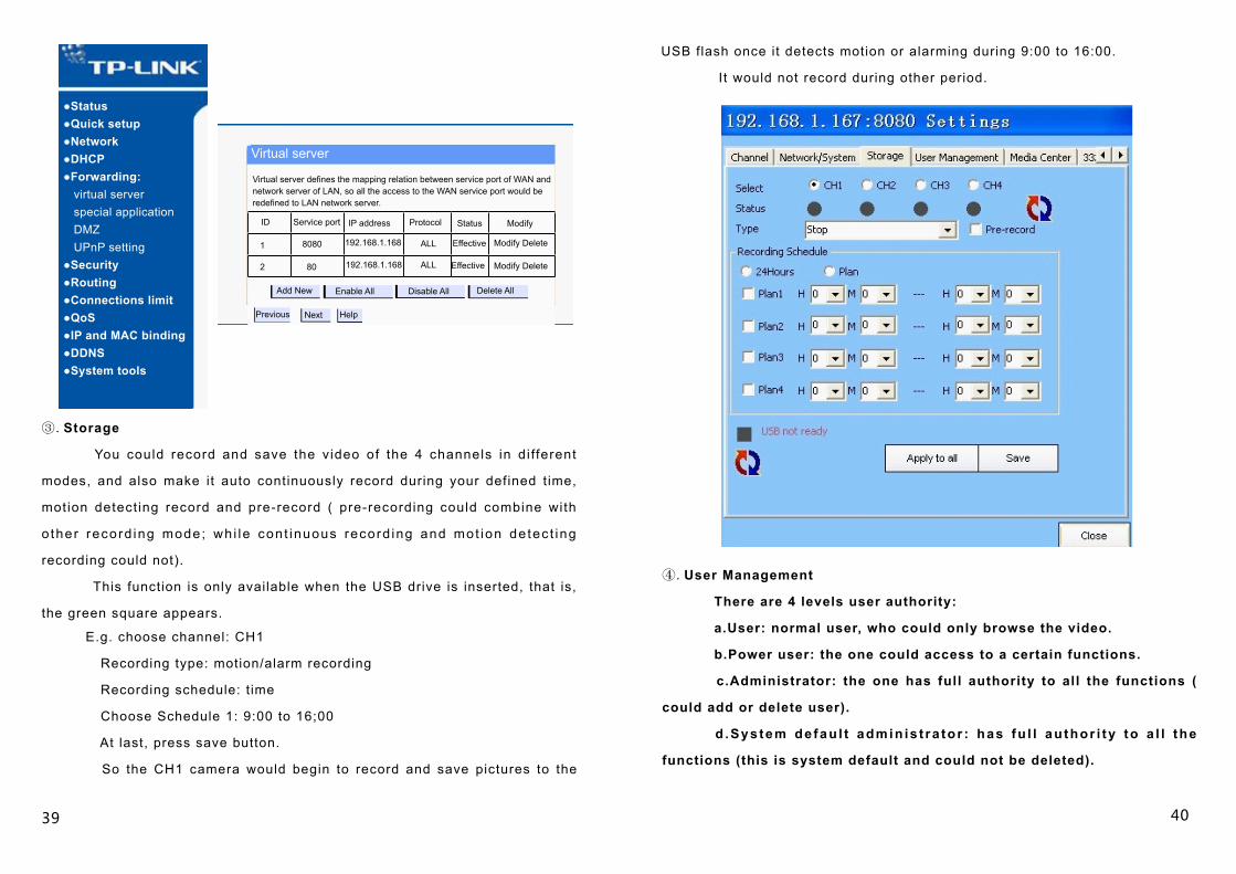
③.Storage
You could record and save the video of the 4 channels in di fferent
modes, and also make it auto continuously record during your defined time,
motion detect ing record and pre-record ( pre-recording could combine with
o ther record ing mode; wh i le con t inuous record ing and mot ion de tec t ing
recording could not).
This function is only available when the USB drive is inserted, that is,
the green square appears.
●Status●Quick setup●Network●DHCP●Forwarding: virtual server special application DMZ UPnP setting●Security●Routing●Connections limit●QoS●IP and MAC binding●DDNS●System tools
Virtual server
Virtual server defines the mapping relation between service port of WAN and network server of LAN, so all the access to the WAN service port would be redefined to LAN network server.
Service port IP address Protocol Status ModifyID
1
2
8080
80
192.168.1.168
192.168.1.168
ALL
ALL
Effective
Effective
Modify Delete
Modify Delete
Add New Enable All Disable All Delete All
Previous Next Help
E.g. choose channel: CH1
Recording type: motion/alarm recording
Recording schedule: t ime
Choose Schedule 1: 9:00 to 16;00
At last, press save button.
So the CH1 camera would begin to record and save pictures to the
USB flash once it detects motion or alarming during 9:00 to 16:00.
It would not record during other period.
④.User Management
There are 4 levels user authority:
a.User: normal user, who could only browse the video.
b.Power user: the one could access to a certain functions.
c.Administrator: the one has full authority to all the functions (
could add or delete user).
d .Sys tem de fau l t admin is t ra tor : has fu l l au thor i ty to a l l the
functions (this is system default and could not be deleted).
41 42
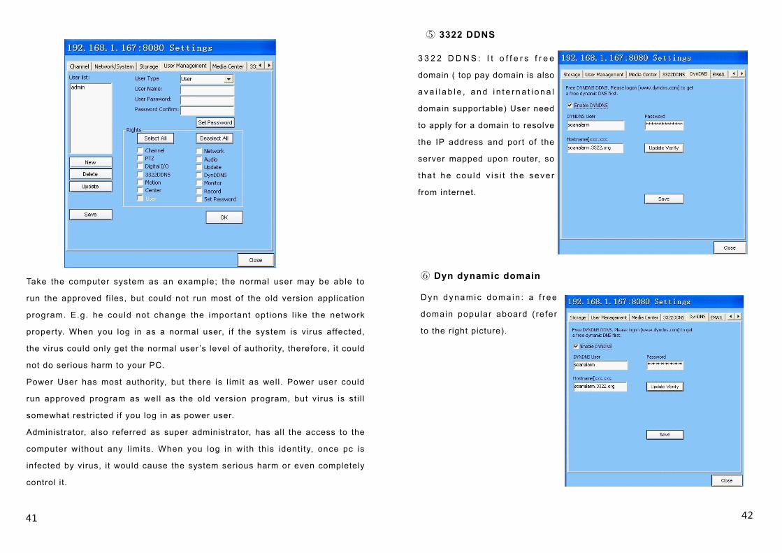
Take the computer system as an example; the normal user may be able to
run the approved fi les, but could not run most of the old version application
program. E.g. he could not change the important opt ions l ike the network
property. When you log in as a normal user, i f the system is virus affected,
the virus could only get the normal user ’s level of authority, therefore, it could
not do serious harm to your PC.
Power User has most authority, but there is l imit as well. Power user could
run approved program as wel l as the old version program, but virus is st i l l
somewhat restricted if you log in as power user.
Administrator, also referred as super administrator, has all the access to the
computer without any l imits. When you log in with this ident i ty, once pc is
infected by virus, it would cause the system serious harm or even completely
control it.
3 3 2 2 D D N S : I t o f f e r s f r e e
domain ( top pay domain is also
a v a i l a b l e , a n d i n t e r n a t i o n a l
domain supportable) User need
to apply for a domain to resolve
the IP address and port of the
server mapped upon router, so
tha t he cou ld v i s i t t he seve r
from internet.
⑤ 3322 DDNS
⑥ Dyn dynamic domain
Dyn dynam ic doma in : a f r ee
domain popular aboard ( re fer
to the right picture).
43 44
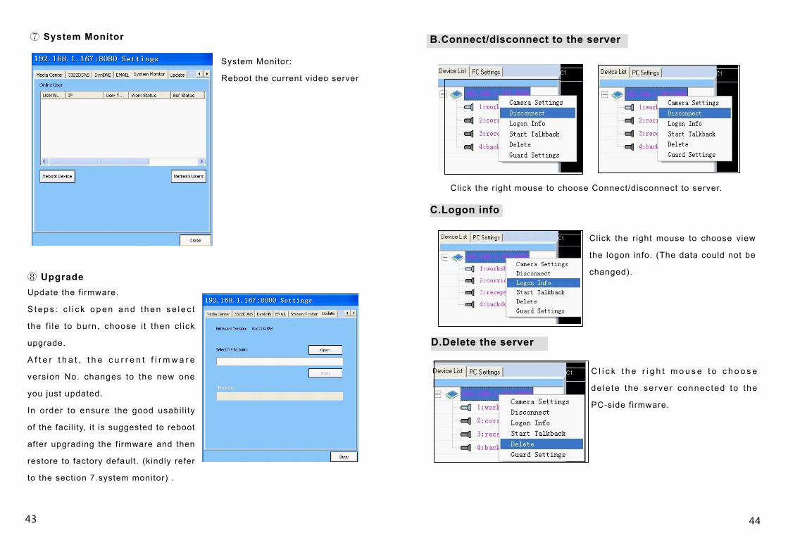
⑦ System Monitor
System Monitor:
Reboot the current video server
⑧ UpgradeUpdate the firmware.
S t e p s : c l i c k o p e n a n d t h e n s e l e c t
the f i le to burn, choose i t then c l ick
upgrade.
A f t e r t h a t , t h e c u r r e n t f i r m w a r e
version No. changes to the new one
you just updated.
In order to ensure the good usabi l i ty
of the facil ity, it is suggested to reboot
after upgrading the firmware and then
restore to factory default. (kindly refer
to the section 7.system monitor) .
B.Connect/disconnect to the server
Click the right mouse to choose Connect/disconnect to server.
C.Logon info
Click the right mouse to choose view
the logon info. (The data could not be
changed).
D.Delete the server
C l i c k t h e r i g h t m o u s e t o c h o o s e
de le te the se rver connec ted to the
PC-side firmware.
45 46
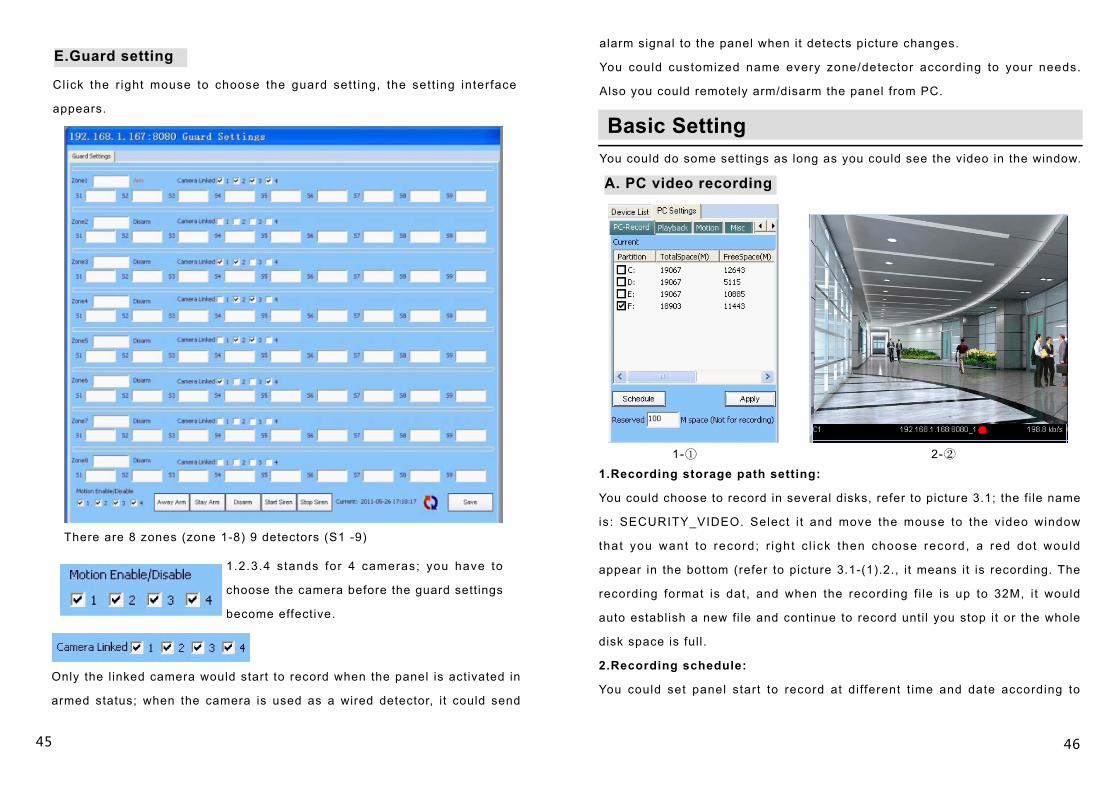
E.Guard setting
Click the r ight mouse to choose the guard sett ing, the sett ing interface
appears.
There are 8 zones (zone 1-8) 9 detectors (S1 -9)
1.2.3.4 stands for 4 cameras; you have to
choose the camera before the guard settings
become effective.
Only the l inked camera would start to record when the panel is activated in
armed status; when the camera is used as a wired detector, it could send
alarm signal to the panel when it detects picture changes.
You could customized name every zone/detector according to your needs.
Also you could remotely arm/disarm the panel from PC.
Basic SettingYou could do some settings as long as you could see the video in the window.
A. PC video recording
1.Recording storage path setting:
You could choose to record in several disks, refer to picture 3.1; the fi le name
is : SECURITY_VIDEO. Select i t and move the mouse to the video window
that you want to record; r ight c l ick then choose record, a red dot would
appear in the bottom (refer to picture 3.1-(1).2., it means it is recording. The
recording format is dat, and when the recording f i le is up to 32M, i t would
auto establish a new fi le and continue to record unti l you stop it or the whole
disk space is full.
2.Recording schedule:
You could set panel start to record at di fferent t ime and date according to
1-① 2-②
47
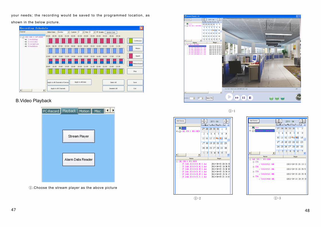
your needs; the recording would be saved to the programmed locat ion, as
shown in the below picture.
①.Choose the stream player as the above picture
①-1
①-2 ①-3
48
B.Video Playback
Stream Player
Add Device
Local
Name Begin
Add Device
Local Local
Add Device
Name BeginName Begin
Partition Open File
Click Add device could playback video of other devices.
Double c l ick Local , re fer to 1) -2) , be low the f i le name IP-192.168.1.168:
8080, i t shows the disk where you saved the recording to. (e.g. that picture
1)-1 shows that recording would be in disk F), the camera l inked (CH1, CH2,
CH3, CH4) and also the recording t ime and date. If the red square appears
in the date column, that means, there is recording on that date. Double click
that date, the related devices would appear in the window; select the device
and channel you want to see, and click play then you could see the recording
playback.
All the recording are kept in the current pc.
Double cl ick the device IP 192.168.1.168: 8080 refer to picture 1)-3. Below
the f i le name i t shows the l inked camera (CH1, CH2, CH3, CH4) and also
the recording t ime and date. Below every camera is i ts recorded video f i le.
The f i le is saved to the panel USB flash (refer to the storage part of server
setting) Double click the fi le to playback the recording.
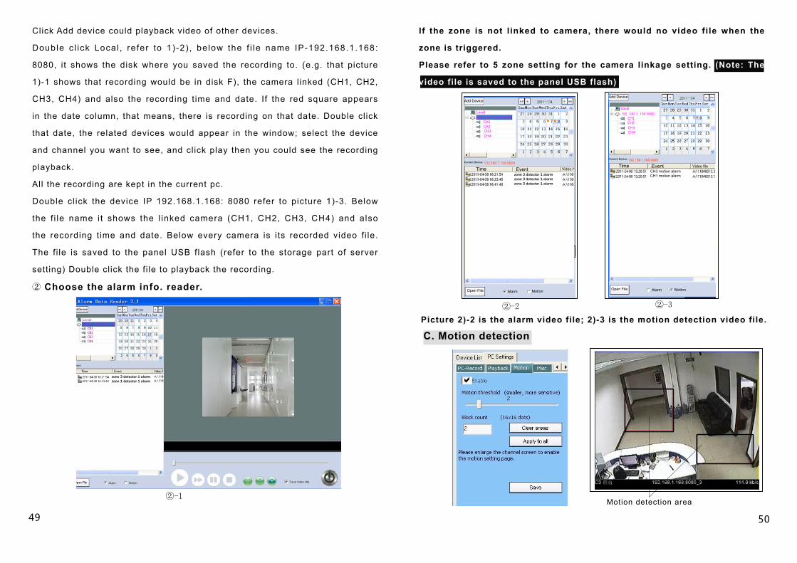
② Choose the alarm info. reader.
If the zone is not l inked to camera, there would no video file when the
zone is triggered.
Please refer to 5 zone setting for the camera linkage setting. (Note: The
video file is saved to the panel USB flash)
②-2 ②-3
②-1
Picture 2)-2 is the alarm video file; 2)-3 is the motion detection video file.
C. Motion detection
Motion detection area
49 50
Add DeviceAdd Device
Local
CH1CH2CH3CH4
Local
CH1CH2CH3CH4
Current Device:Current Device:
zone 3 detector 1 alarmzone 3 detector 1 alarmzone 3 detector 1 alarm
CH3 motion alarmCH1 motion alarm
Time Event Video fTime Event Video file
Open File Alarm Motion Open File Alarm Motion
zone 3 detector 1 alarmzone 1 detector 1 alarm
Select the channel screen that you want to enable the motion detection
function, double click it to enlarge it; set the sensitivity and enable it.
Then mark the motion detecting area ( It is no problem to mark 2 areas
in one screen) at last, save it and double click the screen to return to its
original size. Until now, the motion detection is successfully enabled.D. User Management
U s e r c o u l d s e t t h e a l a r m p r o m p t
sound; You could choose panel alarms
with PC audio card or with appointed
audio file. ( the alarm sound could be a
song or a sentence)
N o t e : i t o n l y s u p p o r t s a u d i o f i l e i n
WAV format.
Also user could choose to reconnect
a u t o m a t i c a l l y w h e n t h e n e t w o r k i s
disconnected.
E. U-disk repair
It is suggested to format your u-disk
before using i t , so that the recorded
file could not be easily damaged.
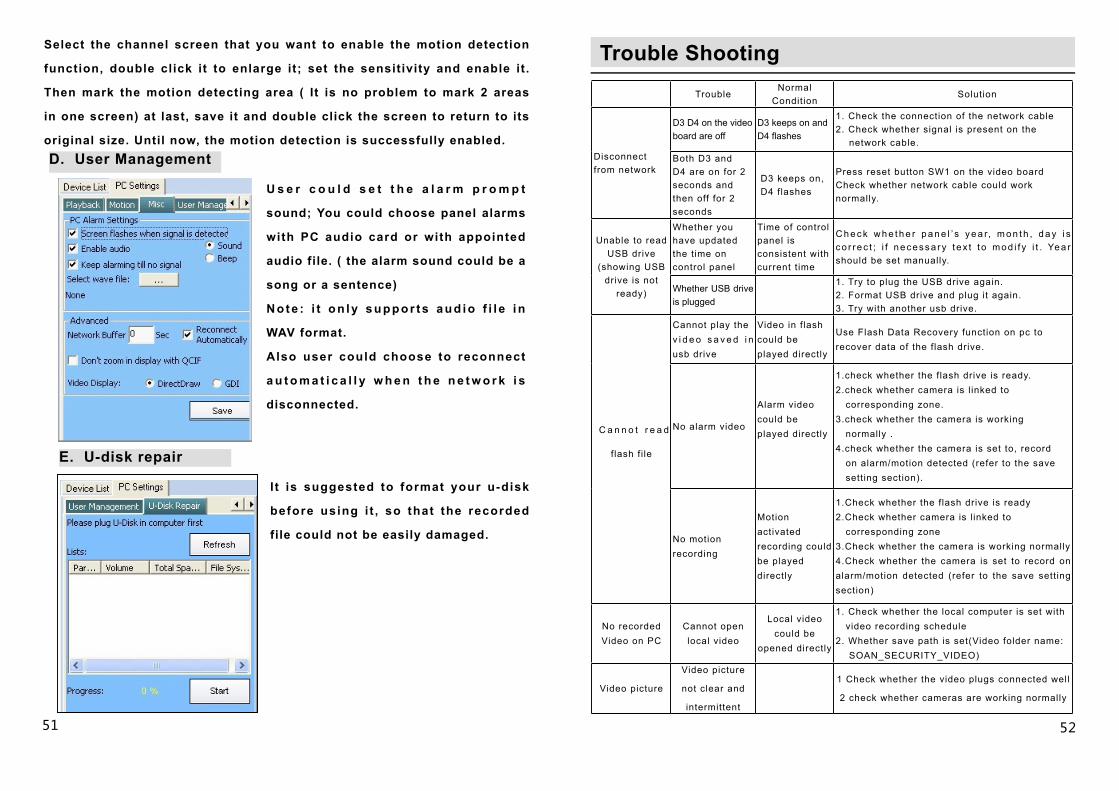
Trouble Shooting
TroubleNormal
Condition Solution
Disconnect from network
D3 D4 on the video board are off
D3 keeps on and D4 flashes
1. Check the connection of the network cable 2. Check whether signal is present on the network cable.
Both D3 and D4 are on for 2 seconds and then off for 2 seconds
D3 keeps on, D4 flashes
Press reset button SW1 on the video boardCheck whether network cable could work normally.
Unable to read USB drive
(showing USB drive is not
ready)
Whether you have updated the time on control panel
Time of control panel is consistent with current t ime
C h e c k w h e t h e r p a n e l ’ s y e a r, m o n t h , d a y i s co r rec t ; i f necessa ry t ex t t o mod i f y i t . Yea r should be set manually.
Whether USB drive is plugged
1. Try to plug the USB drive again.2. Format USB drive and plug it again.3. Try with another usb drive.
C a n n o t r e a d
flash fi le
Cannot play the v i d e o s a v e d i n usb drive
Video in flash could be played directly
Use Flash Data Recovery function on pc to recover data of the flash drive.
No alarm video
Alarm video could be played directly
1.check whether the flash drive is ready.2.check whether camera is l inked to corresponding zone.3.check whether the camera is working normally .4.check whether the camera is set to, record on alarm/motion detected (refer to the save setting section).
No motion recording
Motion activated recording could be played directly
1.Check whether the flash drive is ready2.Check whether camera is l inked to corresponding zone3.Check whether the camera is working normally 4.Check whether the camera is set to record on alarm/motion detected (refer to the save setting section)
No recorded Video on PC
Cannot open local video
Local video could be
opened directly
1. Check whether the local computer is set with video recording schedule2. Whether save path is set(Video folder name: SOAN_SECURITY_VIDEO)
Video picture
Video picture
not clear and
intermittent
1 Check whether the video plugs connected well
2 check whether cameras are working normally
51 52