Embed Size (px)
Citation preview
Version 22.10.2021 HW:CAM(V98/99/100)/(V45/46) RL4-MBN6
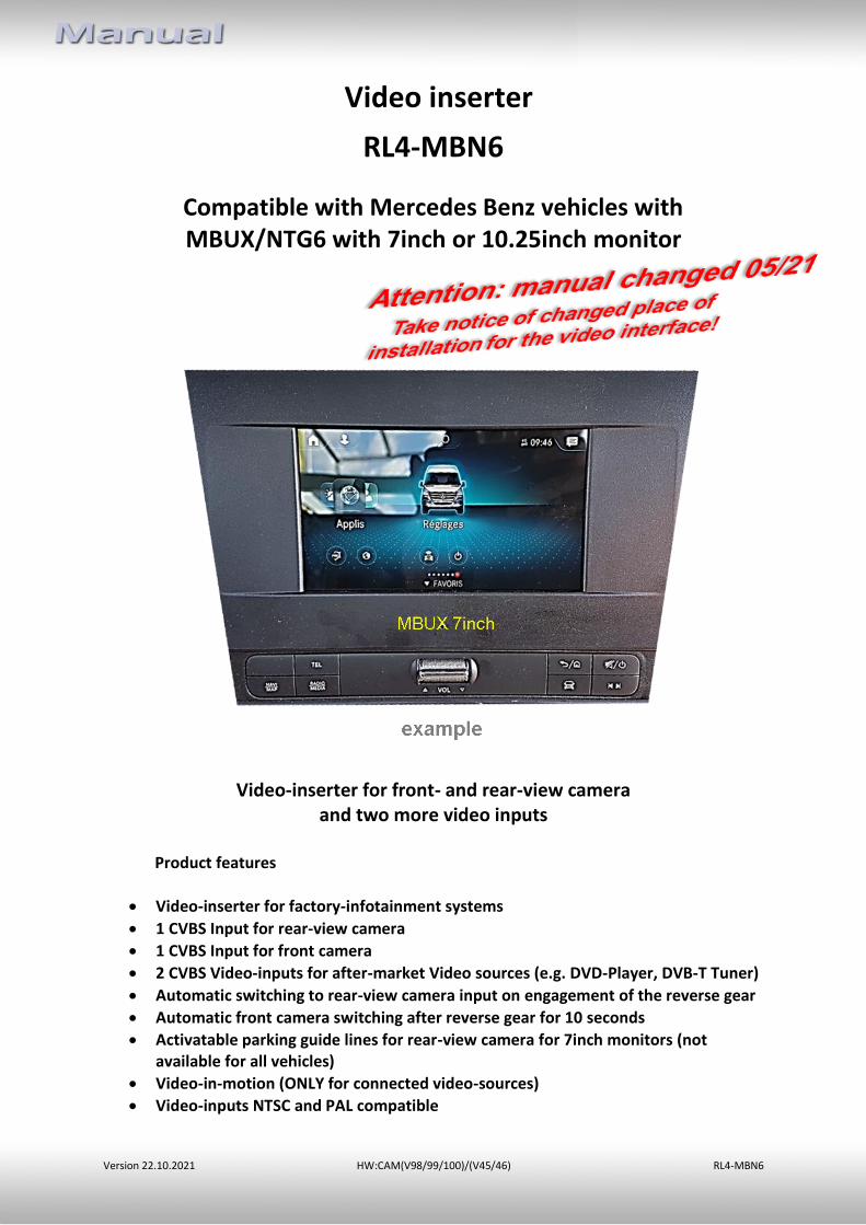
Video inserter
RL4-MBN6
Compatible with Mercedes Benz vehicles with MBUX/NTG6 with 7inch or 10.25inch monitor
Video-inserter for front- and rear-view camera and two more video inputs
Product features
• Video-inserter for factory-infotainment systems
• 1 CVBS Input for rear-view camera
• 1 CVBS Input for front camera
• 2 CVBS Video-inputs for after-market Video sources (e.g. DVD-Player, DVB-T Tuner)
• Automatic switching to rear-view camera input on engagement of the reverse gear
• Automatic front camera switching after reverse gear for 10 seconds
• Activatable parking guide lines for rear-view camera for 7inch monitors (not available for all vehicles)
• Video-in-motion (ONLY for connected video-sources)
• Video-inputs NTSC and PAL compatible
Version 22.10.2021 HW:CAM(V98/99/100)/(V45/46) RL4-MBN6
Pa
ge2
Contents
1. Prior to installation
1.1. Delivery contents 1.2. Checking the compatibility of vehicle and accessories 1.3. Boxes and connectors – video interface 1.4. Settings of the 8 Dip switches (black) 1.4.1. Adjustment – power supply output (dip 1) 1.4.2. Enabling the interface’s video inputs (dip 2-3) 1.4.3. Rear-view camera settings (dip 5) 1.4.4. Activating – front camera back-switching (dip6) 1.4.5. Activating the guide lines (dip 7) 1.4.6. Monitor selection (Dip 8) 1.5. Settings - 6 Dip switches (Top of box–black) 1.6. Settings of the 4 Dip switches (CAN function – red)
2. Installation
2.1. Place of connection 2.1.1. Removing the MBUX head-unit in the Sprinter (W907) 2.1.2. Place of installation – RL4-MBN6 2.2. Connection schema 2.3. Connection 2.3.1. Picture signal cable - Head unit type 1 2.3.2. Picture signal cable - Head unit type 2 2.3.3. 10pin Power/CAN cable 2.3.4. Installation with connection to CAN bus or analogue (without CAN bus) 2.3.4.1. Place of connection 2.3.4.2. Alternative connection point Power/CAN - Sprinter W907/910 2.3.4.3. Installation with analogue connection (without CAN-Bus) 2.3.5. After-market rear-view camera 2.3.5.1. Case 1: Interface receives the reverse gear signal 2.3.5.2. Case 2: Interface does not receive the reverse gear signal 2.3.6. Power supply output 2.3.6.1. After-market front camera 2.4. Connection - video-interface and external keypad 2.5. Connection - video-sources 2.6. Audio insertion 2.7. Picture settings and guide lines
3. Interface operation 4. Specifications
5. FAQ – Trouble Shooting-Interface functions
6. Technical support
Version 22.10.2021 HW:CAM(V98/99/100)/(V45/46) RL4-MBN6
Pa
ge3
Legal Information
By law, watching moving pictures while driving is prohibited, the driver must not be distracted. We do not accept any liability for material damage or personal injury resulting, directly or indirectly, from installation or operation of this product. Apart from using this product in an unmoved vehicle, it should only be used to display fixed menus or rear-view-camera video when the vehicle is moving (for example the MP3 menu for DVD upgrades).
Changes/updates of the vehicle’s software can cause malfunctions of the interface. Up to one year after purchase we offer free software-updates for our interfaces. To receive a free update, the interface has to be sent in at own cost. Wages for de-and reinstallation and other expenditures involved with the software-updates will not be refunded.
1. Prior to installation
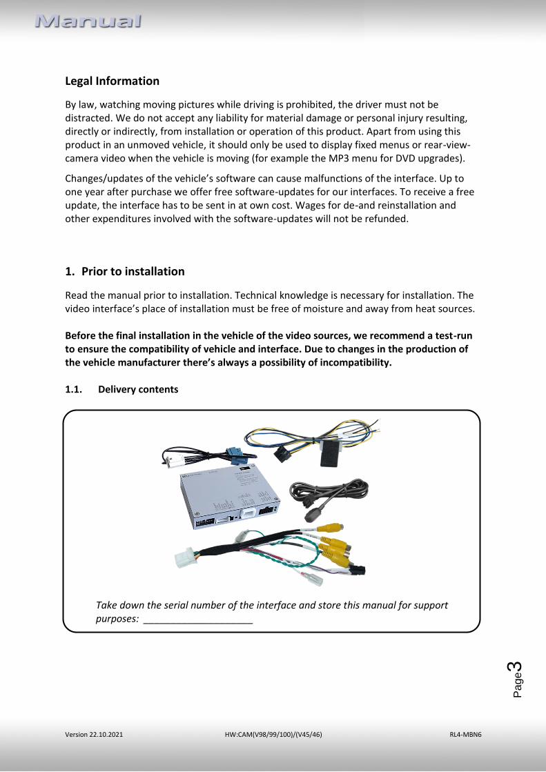
Read the manual prior to installation. Technical knowledge is necessary for installation. The video interface’s place of installation must be free of moisture and away from heat sources. Before the final installation in the vehicle of the video sources, we recommend a test-run to ensure the compatibility of vehicle and interface. Due to changes in the production of the vehicle manufacturer there’s always a possibility of incompatibility. 1.1. Delivery contents
Take down the serial number of the interface and store this manual for support purposes: ____________________
Version 22.10.2021 HW:CAM(V98/99/100)/(V45/46) RL4-MBN6
Pa
ge4
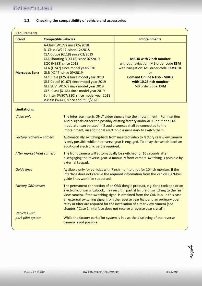
Requirements
Brand Compatible vehicles Infotainments
Mercedes Benz
A-Class (W177) since 05/2018 B- Class (W247) since 12/2018 CLA Coupé (C118) since 03/2019 CLA Shooting B (X118) since 07/2019 EQC (N293) since 2019 GLA (H247) since model year2020 GLB (X247) since 09/2019 GLC Class (X253) since model year 2019 GLE Coupé (C167) since model year 2019 GLE SUV (W167) since model year 2019 GLS- Class (X166) since model year 2019 Sprinter (W907/910) since model year 2018 V-class (W447) since about 03/2020
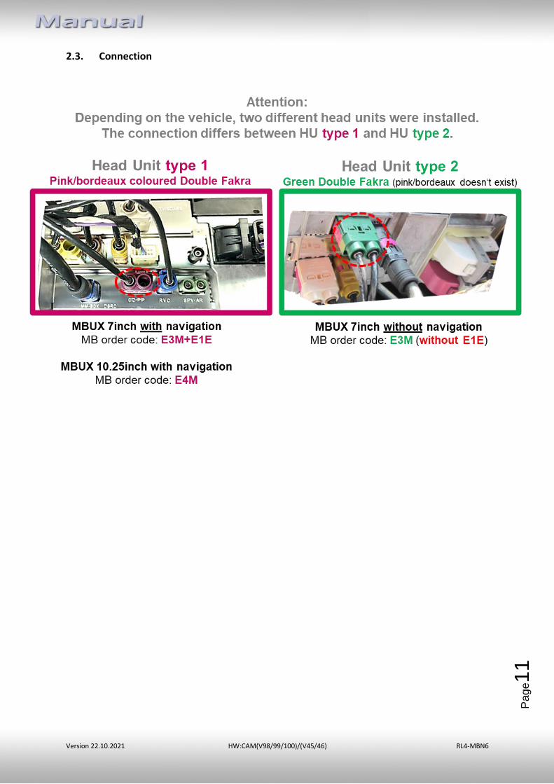
MBUX with 7inch monitor without navigation: MB order code E3M
with navigation: MB order code E3M+E1E or
Comand Online NTG6 - MBUX with 10.25inch monitor
MB order code: E4M
Limitations:
Video only The interface inserts ONLY video signals into the infotainment. For inserting Audio signals either the possibly existing factory audio-AUX-input or a FM-modulator can be used. If 2 audio sources shall be connected to the infotainment, an additional electronic is necessary to switch them.
Factory rear-view camera Automatically switching-back from inserted video to factory rear-view camera is only possible while the reverse gear is engaged. To delay the switch-back an additional electronic part is required.
After market front camera The front camera will automatically be switched for 10 seconds after disengaging the reverse gear. A manually front camera switching is possible by external keypad.
Guide lines Available only for vehicles with 7inch monitor, not for 10inch monitor. If the interface does not receive the required information from the vehicle CAN-bus, guide lines won’t be supported.
Factory OBD socket The permanent connection of an OBD dongle product, e.g. for a tank app or an electronic driver's logbook, may result in partial failure of switching to the rear view camera. if the switching signal is obtained from the CAN bus. In this case an external switching signal from the reverse gear light and an ordinary open relay or filter are required for the installation of a rear-view camera (see chapter: "Case 2: Interface does not receive a reverse gear signal").
Vehicles with park pilot system While the factory park pilot system is in use, the displaying of the reverse
camera is not possible.
1.2. Checking the compatibility of vehicle and accessories
Version 22.10.2021 HW:CAM(V98/99/100)/(V45/46) RL4-MBN6
Pa
ge5
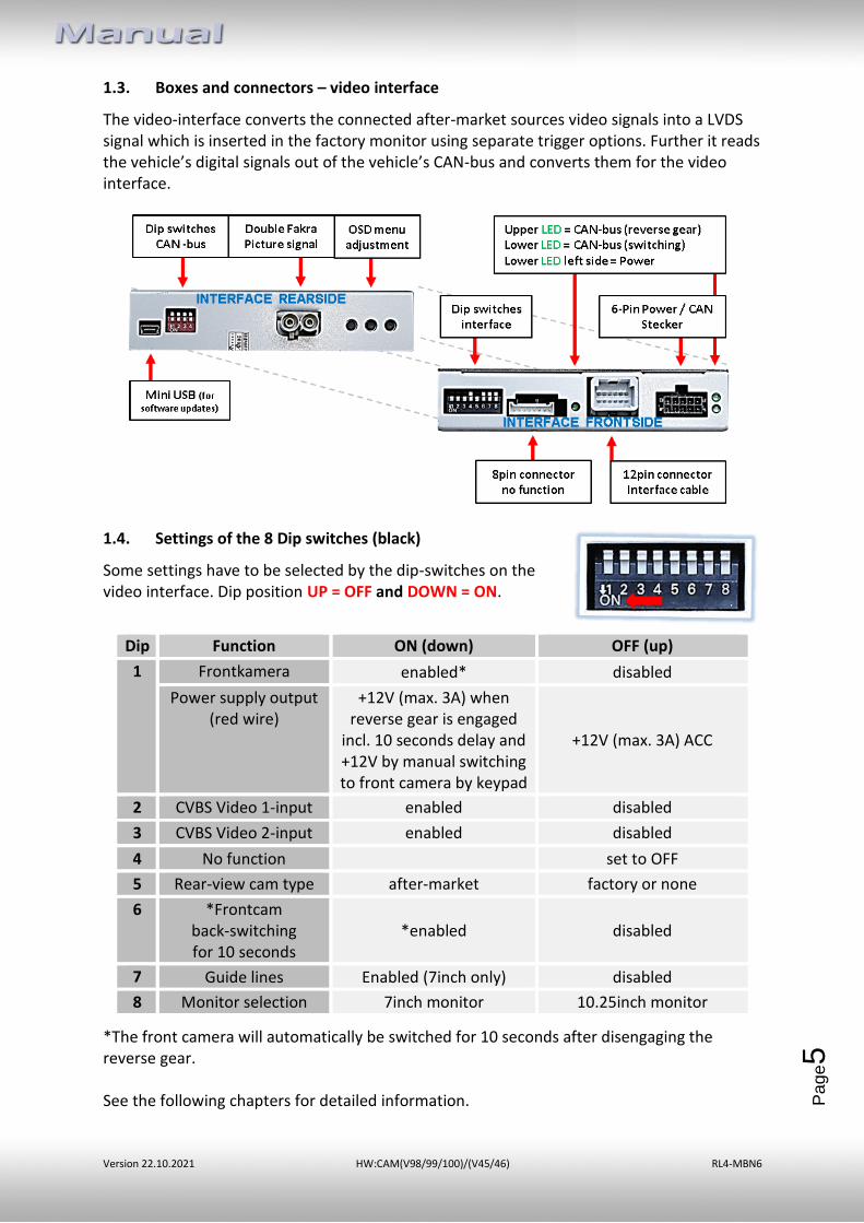
1.3. Boxes and connectors – video interface
The video-interface converts the connected after-market sources video signals into a LVDS signal which is inserted in the factory monitor using separate trigger options. Further it reads the vehicle’s digital signals out of the vehicle’s CAN-bus and converts them for the video interface.
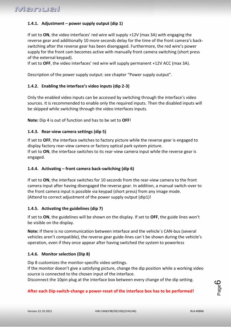
1.4. Settings of the 8 Dip switches (black)
Some settings have to be selected by the dip-switches on the video interface. Dip position UP = OFF and DOWN = ON.
*The front camera will automatically be switched for 10 seconds after disengaging the reverse gear. See the following chapters for detailed information.
Dip Function ON (down) OFF (up)
1 Frontkamera enabled* disabled
Power supply output (red wire)
+12V (max. 3A) when reverse gear is engaged
incl. 10 seconds delay and +12V by manual switching to front camera by keypad
+12V (max. 3A) ACC
2 CVBS Video 1-input enabled disabled
3 CVBS Video 2-input enabled disabled
4 No function set to OFF
5 Rear-view cam type after-market factory or none
6 *Frontcam back-switching for 10 seconds
*enabled disabled
7 Guide lines Enabled (7inch only) disabled
8 Monitor selection 7inch monitor 10.25inch monitor
Version 22.10.2021 HW:CAM(V98/99/100)/(V45/46) RL4-MBN6
Pa
ge6
1.4.1. Adjustment – power supply output (dip 1) If set to ON, the video interfaces’ red wire will supply +12V (max 3A) with engaging the reverse gear and additionally 10 more seconds delay for the time of the front camera’s back-switching after the reverse gear has been disengaged. Furthermore, the red wire’s power supply for the front cam becomes active with manually front camera switching (short press of the external keypad). If set to OFF, the video interfaces’ red wire will supply permanent +12V ACC (max 3A). Description of the power supply output: see chapter “Power supply output”. 1.4.2. Enabling the interface’s video inputs (dip 2-3)
Only the enabled video inputs can be accessed by switching through the interface’s video sources. It is recommended to enable only the required inputs. Then the disabled inputs will be skipped while switching through the video interfaces inputs. Note: Dip 4 is out of function and has to be set to OFF! 1.4.3. Rear-view camera settings (dip 5)
If set to OFF, the interface switches to factory picture while the reverse gear is engaged to display factory rear-view camera or factory optical park system picture. If set to ON, the interface switches to its rear-view camera input while the reverse gear is engaged. 1.4.4. Activating – front camera back-switching (dip 6) If set to ON, the interface switches for 10 seconds from the rear-view camera to the front camera input after having disengaged the reverse gear. In addition, a manual switch-over to the front camera input is possible via keypad (short press) from any image mode. (Attend to correct adjustment of the power supply output (dip1)! 1.4.5. Activating the guidelines (dip 7)
If set to ON, the guidelines will be shown on the display. If set to OFF, the guide lines won’t be visible on the display.
Note: If there is no communication between interface and the vehicle`s CAN-bus (several vehicles aren’t compatible), the reverse gear guide-lines can`t be shown during the vehicle’s operation, even if they once appear after having switched the system to powerless 1.4.6. Monitor selection (Dip 8)
Dip 8 customizes the monitor-specific video settings. If the monitor doesn’t give a satisfying picture, change the dip position while a working video source is connected to the chosen input of the interface. Disconnect the 10pin plug at the interface box between every change of the dip setting. After each Dip-switch-change a power-reset of the interface box has to be performed!
Version 22.10.2021 HW:CAM(V98/99/100)/(V45/46) RL4-MBN6
Pa
ge7
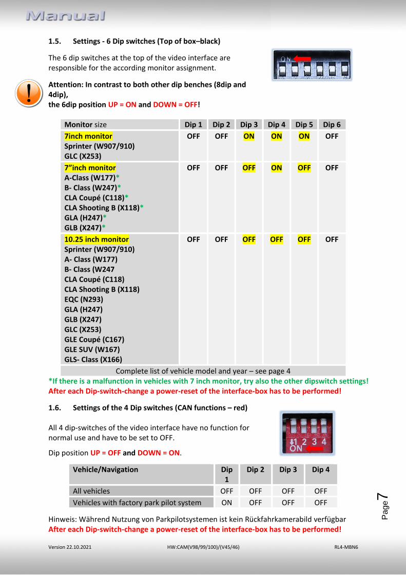
1.5. Settings - 6 Dip switches (Top of box–black)
The 6 dip switches at the top of the video interface are responsible for the according monitor assignment.
Attention: In contrast to both other dip benches (8dip and 4dip), the 6dip position UP = ON and DOWN = OFF!
Monitor size Dip 1 Dip 2 Dip 3 Dip 4 Dip 5 Dip 6
7inch monitor Sprinter (W907/910) GLC (X253)
OFF OFF ON ON ON OFF
7”inch monitor A-Class (W177)* B- Class (W247)* CLA Coupé (C118)* CLA Shooting B (X118)* GLA (H247)* GLB (X247)*
OFF OFF OFF ON OFF OFF
10.25 inch monitor Sprinter (W907/910) A- Class (W177) B- Class (W247 CLA Coupé (C118) CLA Shooting B (X118) EQC (N293) GLA (H247) GLB (X247) GLC (X253) GLE Coupé (C167) GLE SUV (W167) GLS- Class (X166)
OFF OFF OFF OFF OFF OFF
Complete list of vehicle model and year – see page 4 *If there is a malfunction in vehicles with 7 inch monitor, try also the other dipswitch settings! After each Dip-switch-change a power-reset of the interface-box has to be performed!
1.6. Settings of the 4 Dip switches (CAN functions – red) All 4 dip-switches of the video interface have no function for normal use and have to be set to OFF.
Dip position UP = OFF and DOWN = ON.
Vehicle/Navigation Dip 1
Dip 2 Dip 3 Dip 4
All vehicles OFF OFF OFF OFF
Vehicles with factory park pilot system ON OFF OFF OFF
Hinweis: Während Nutzung von Parkpilotsystemen ist kein Rückfahrkamerabild verfügbar After each Dip-switch-change a power-reset of the interface-box has to be performed!
Version 22.10.2021 HW:CAM(V98/99/100)/(V45/46) RL4-MBN6
Pa
ge8
2. Installation
To install the interface, first switch off the ignition and disconnect the vehicle’s battery. Please read the owner`s manual of the car, regarding the battery`s disconnection! If required, enable the car`s Sleep-mode (hibernation mode) In case the sleep-mode does not succeed, the disconnection of the battery can be done with a resistor lead. If the necessary stabilized power supply for the interface is not taken directly from the battery, the chosen connection has to be checked for being constantly stabile. The interface needs a permanent 12V source! 2.1. Place of connection
Depending on the vehicle model, the place of installation of the MBUX head unit to which the connection is made, varies. Examples:
• A-Class (W177), B-Class W247), GLA (H247): On the A-pillar on the driver's side
• GLE (W167 und C167): Under the passenger seat
• Sprinter (W907/910): Behind the factory monitor
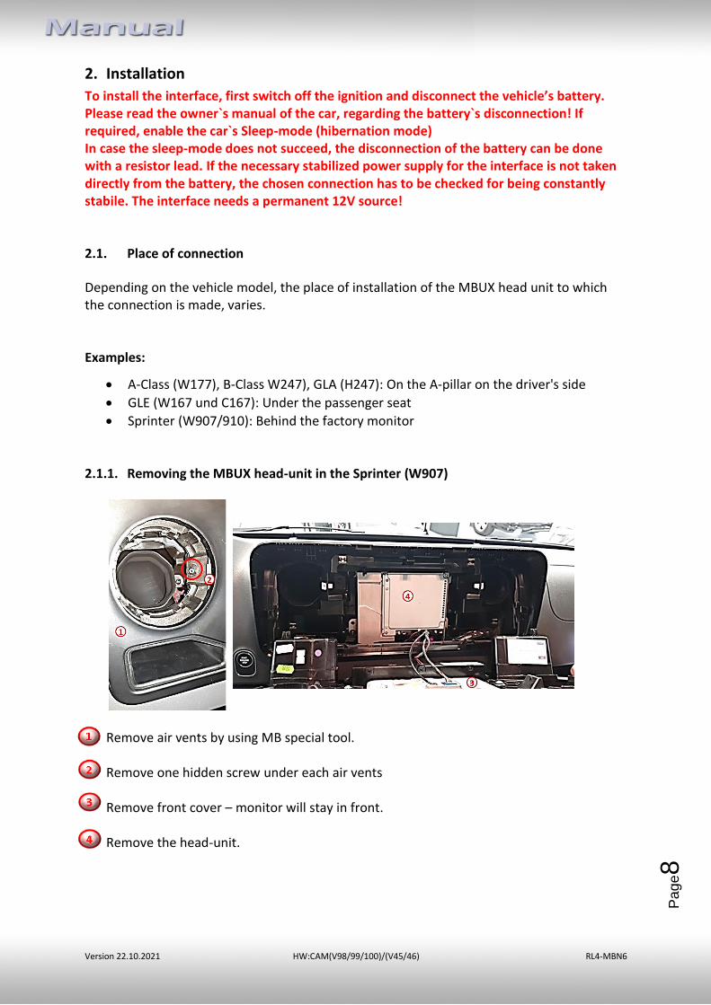
2.1.1. Removing the MBUX head-unit in the Sprinter (W907)
Remove air vents by using MB special tool. Remove one hidden screw under each air vents
Remove front cover – monitor will stay in front. Remove the head-unit.
Version 22.10.2021 HW:CAM(V98/99/100)/(V45/46) RL4-MBN6
Pa
ge9
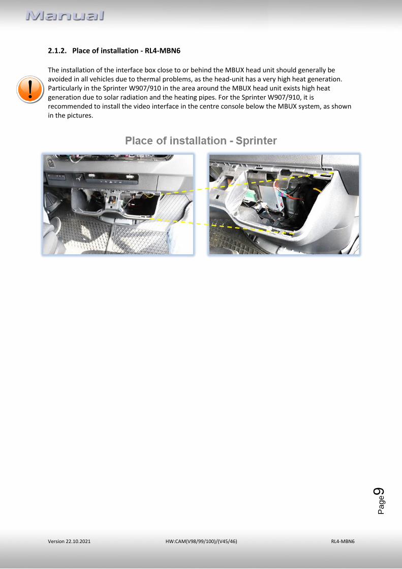
2.1.2. Place of installation - RL4-MBN6 The installation of the interface box close to or behind the MBUX head unit should generally be avoided in all vehicles due to thermal problems, as the head-unit has a very high heat generation. Particularly in the Sprinter W907/910 in the area around the MBUX head unit exists high heat generation due to solar radiation and the heating pipes. For the Sprinter W907/910, it is recommended to install the video interface in the centre console below the MBUX system, as shown in the pictures.
Version 22.10.2021 HW:CAM(V98/99/100)/(V45/46) RL4-MBN6
Pa
ge1
0
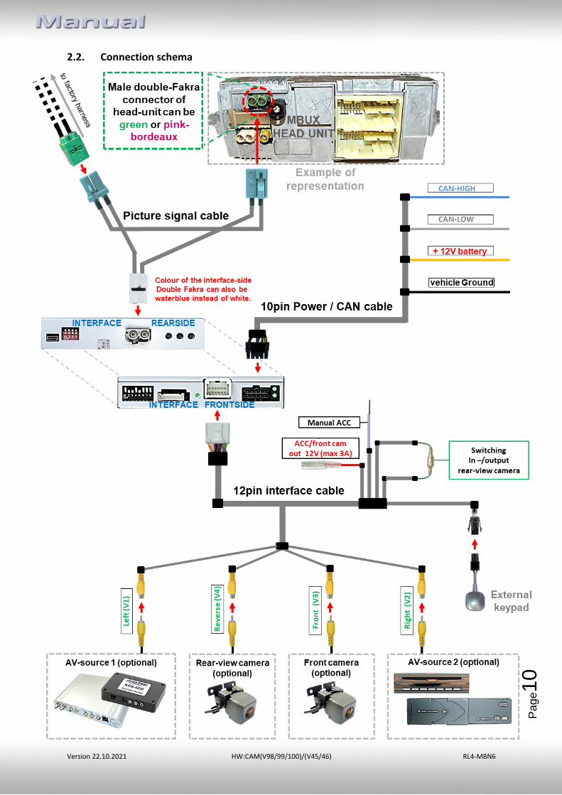
2.2. Connection schema
Version 22.10.2021 HW:CAM(V98/99/100)/(V45/46) RL4-MBN6
Pa
ge1
1
2.3. Connection
Version 22.10.2021 HW:CAM(V98/99/100)/(V45/46) RL4-MBN6
Pa
ge1
2
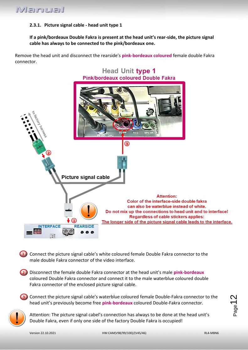
2.3.1. Picture signal cable - head unit type 1
If a pink/bordeaux Double Fakra is present at the head unit’s rear-side, the picture signal cable has always to be connected to the pink/bordeaux one.
Remove the head unit and disconnect the rearside’s pink-bordeaux coloured female double Fakra connector.
Connect the picture signal cable’s white coloured female Double Fakra connector to the male double Fakra connector of the video interface. Disconnect the female double Fakra connector at the head unit’s male pink-bordeaux coloured Double Fakra connector and connect it to the male waterblue coloured double Fakra connector of the enclosed picture signal cable. Connect the picture signal cable’s waterblue coloured female Double-Fakra connector to the head unit’s previously become free pink-bordeaux coloured Double-Fakra connector.
Attention: The picture signal cabel’s connection has always to be done at the head unit’s Double Fakra, even if only one side of the factory Double Fakra is occupied!
Version 22.10.2021 HW:CAM(V98/99/100)/(V45/46) RL4-MBN6
Pa
ge1
3
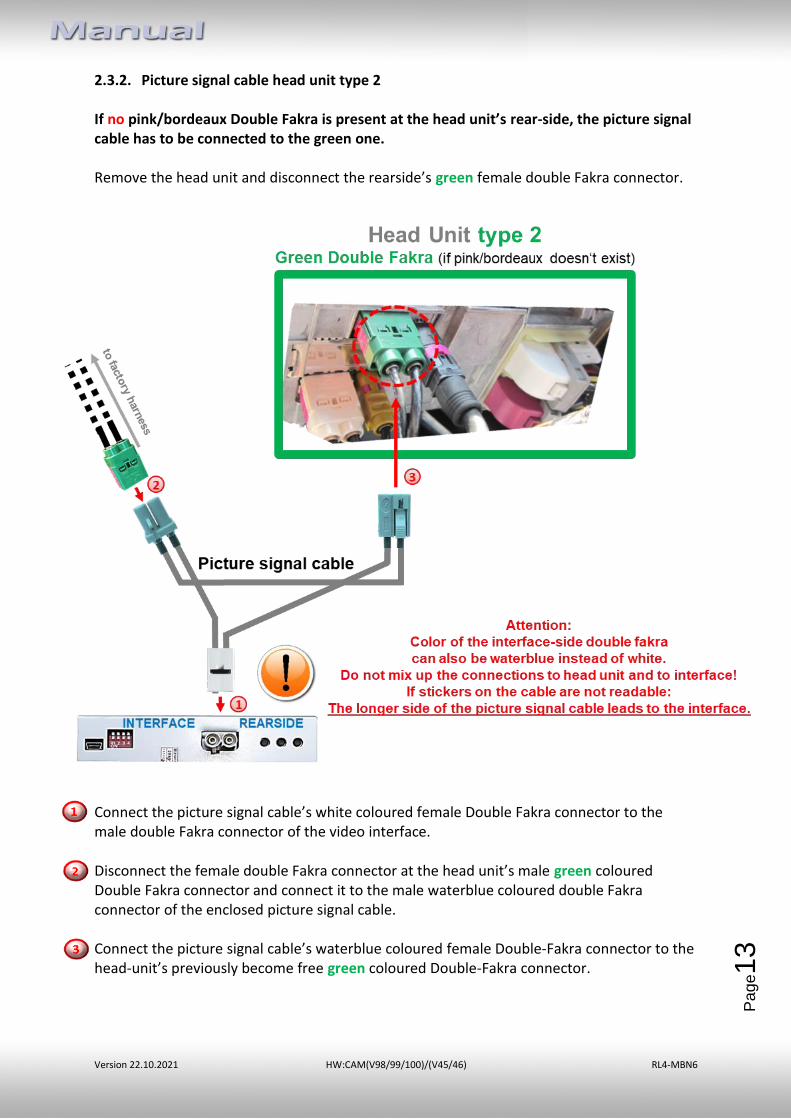
2.3.2. Picture signal cable head unit type 2
If no pink/bordeaux Double Fakra is present at the head unit’s rear-side, the picture signal cable has to be connected to the green one. Remove the head unit and disconnect the rearside’s green female double Fakra connector.
Connect the picture signal cable’s white coloured female Double Fakra connector to the male double Fakra connector of the video interface. Disconnect the female double Fakra connector at the head unit’s male green coloured Double Fakra connector and connect it to the male waterblue coloured double Fakra connector of the enclosed picture signal cable. Connect the picture signal cable’s waterblue coloured female Double-Fakra connector to the head-unit’s previously become free green coloured Double-Fakra connector.
Version 22.10.2021 HW:CAM(V98/99/100)/(V45/46) RL4-MBN6
Pa
ge1
4
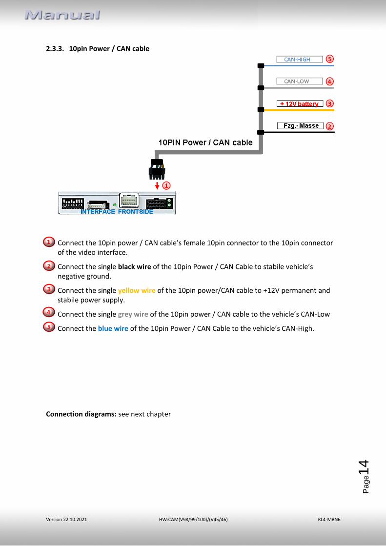
2.3.3. 10pin Power / CAN cable
Connect the 10pin power / CAN cable’s female 10pin connector to the 10pin connector of the video interface.
Connect the single black wire of the 10pin Power / CAN Cable to stabile vehicle’s negative ground.
Connect the single yellow wire of the 10pin power/CAN cable to +12V permanent and stabile power supply.
Connect the single grey wire of the 10pin power / CAN cable to the vehicle’s CAN-Low
Connect the blue wire of the 10pin Power / CAN Cable to the vehicle’s CAN-High.
Connection diagrams: see next chapter
Version 22.10.2021 HW:CAM(V98/99/100)/(V45/46) RL4-MBN6
Pa
ge1
5
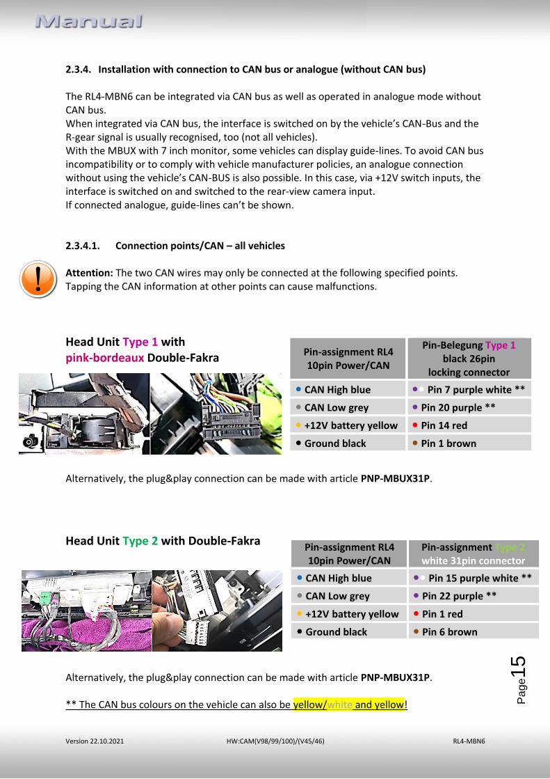
2.3.4. Installation with connection to CAN bus or analogue (without CAN bus) The RL4-MBN6 can be integrated via CAN bus as well as operated in analogue mode without CAN bus. When integrated via CAN bus, the interface is switched on by the vehicle’s CAN-Bus and the R-gear signal is usually recognised, too (not all vehicles). With the MBUX with 7 inch monitor, some vehicles can display guide-lines. To avoid CAN bus incompatibility or to comply with vehicle manufacturer policies, an analogue connection without using the vehicle’s CAN-BUS is also possible. In this case, via +12V switch inputs, the interface is switched on and switched to the rear-view camera input. If connected analogue, guide-lines can’t be shown. 2.3.4.1. Connection points/CAN – all vehicles Attention: The two CAN wires may only be connected at the following specified points. Tapping the CAN information at other points can cause malfunctions.
Head Unit Type 1 with pink-bordeaux Double-Fakra
Alternatively, the plug&play connection can be made with article PNP-MBUX31P.
Head Unit Type 2 with Double-Fakra
Alternatively, the plug&play connection can be made with article PNP-MBUX31P. ** The CAN bus colours on the vehicle can also be yellow/white and yellow!
Pin-assignment RL4 10pin Power/CAN
Pin-Belegung Type 1 black 26pin
locking connector
• CAN High blue •• Pin 7 purple white **
• CAN Low grey • Pin 20 purple **
• +12V battery yellow • Pin 14 red
• Ground black • Pin 1 brown
Pin-assignment RL4 10pin Power/CAN
Pin-assignment Type 2 white 31pin connector
• CAN High blue •• Pin 15 purple white **
• CAN Low grey • Pin 22 purple **
• +12V battery yellow • Pin 1 red
• Ground black • Pin 6 brown
Version 22.10.2021 HW:CAM(V98/99/100)/(V45/46) RL4-MBN6
Pa
ge1
6
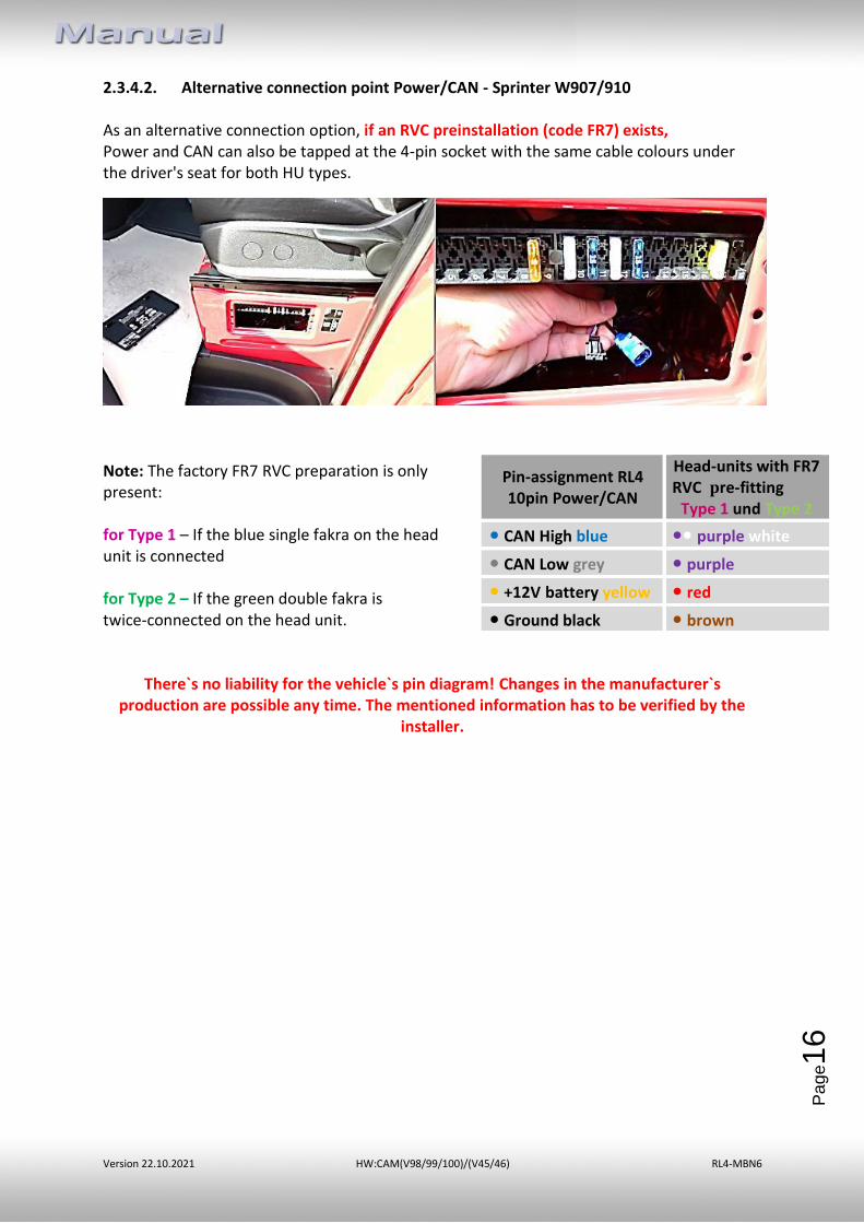
2.3.4.2. Alternative connection point Power/CAN - Sprinter W907/910 As an alternative connection option, if an RVC preinstallation (code FR7) exists, Power and CAN can also be tapped at the 4-pin socket with the same cable colours under the driver's seat for both HU types.
Note: The factory FR7 RVC preparation is only present: for Type 1 – If the blue single fakra on the head unit is connected for Type 2 – If the green double fakra is twice-connected on the head unit.
There`s no liability for the vehicle`s pin diagram! Changes in the manufacturer`s production are possible any time. The mentioned information has to be verified by the
installer.
Pin-assignment RL4 10pin Power/CAN
Head-units with FR7 RVC pre-fitting
Type 1 und Type 2
• CAN High blue •• purple white
• CAN Low grey • purple
• +12V battery yellow • red
• Ground black • brown
Version 22.10.2021 HW:CAM(V98/99/100)/(V45/46) RL4-MBN6
Pa
ge1
7
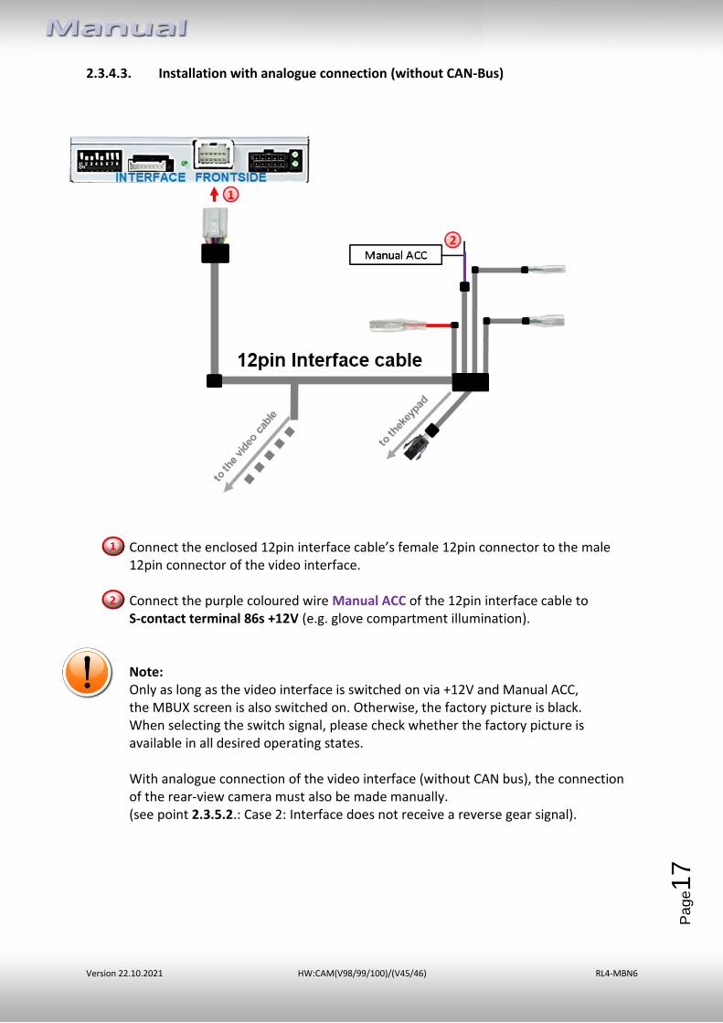
2.3.4.3. Installation with analogue connection (without CAN-Bus)
Connect the enclosed 12pin interface cable’s female 12pin connector to the male 12pin connector of the video interface. Connect the purple coloured wire Manual ACC of the 12pin interface cable to S-contact terminal 86s +12V (e.g. glove compartment illumination). Note: Only as long as the video interface is switched on via +12V and Manual ACC, the MBUX screen is also switched on. Otherwise, the factory picture is black. When selecting the switch signal, please check whether the factory picture is available in all desired operating states. With analogue connection of the video interface (without CAN bus), the connection of the rear-view camera must also be made manually. (see point 2.3.5.2.: Case 2: Interface does not receive a reverse gear signal).
Version 22.10.2021 HW:CAM(V98/99/100)/(V45/46) RL4-MBN6
Pa
ge1
8
2.3.5. Audio-insertion
This interface is only able to insert video signals into the factory infotainment. If an AV-source is connected, the audio insertion has to be done by the factory audio AUX input or an FM-modulator. The inserted video-signal can be activated simultaneously to each audio-mode of the factory infotainment. If 2 AV sources shall be connected to the infotainment, additional electronic is necessary to switch the audio signals.
2.3.6. After-market rear-view camera
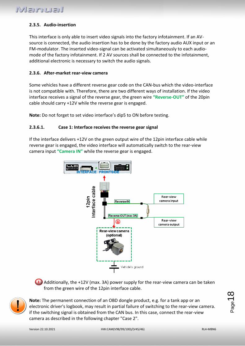
Some vehicles have a different reverse gear code on the CAN-bus which the video-interface is not compatible with. Therefore, there are two different ways of installation. If the video interface receives a signal of the reverse gear, the green wire “Reverse-OUT” of the 20pin cable should carry +12V while the reverse gear is engaged. Note: Do not forget to set video interface’s dip5 to ON before testing. 2.3.6.1. Case 1: Interface receives the reverse gear signal
If the interface delivers +12V on the green output wire of the 12pin interface cable while reverse gear is engaged, the video interface will automatically switch to the rear-view camera input “Camera IN” while the reverse gear is engaged.
Additionally, the +12V (max. 3A) power supply for the rear-view camera can be taken from the green wire of the 12pin interface cable.
Note: The permanent connection of an OBD dongle product, e.g. for a tank app or an electronic driver's logbook, may result in partial failure of switching to the rear-view camera. if the switching signal is obtained from the CAN bus. In this case, connect the rear-view camera as described in the following chapter "Case 2".
Version 22.10.2021 HW:CAM(V98/99/100)/(V45/46) RL4-MBN6
Pa
ge1
9
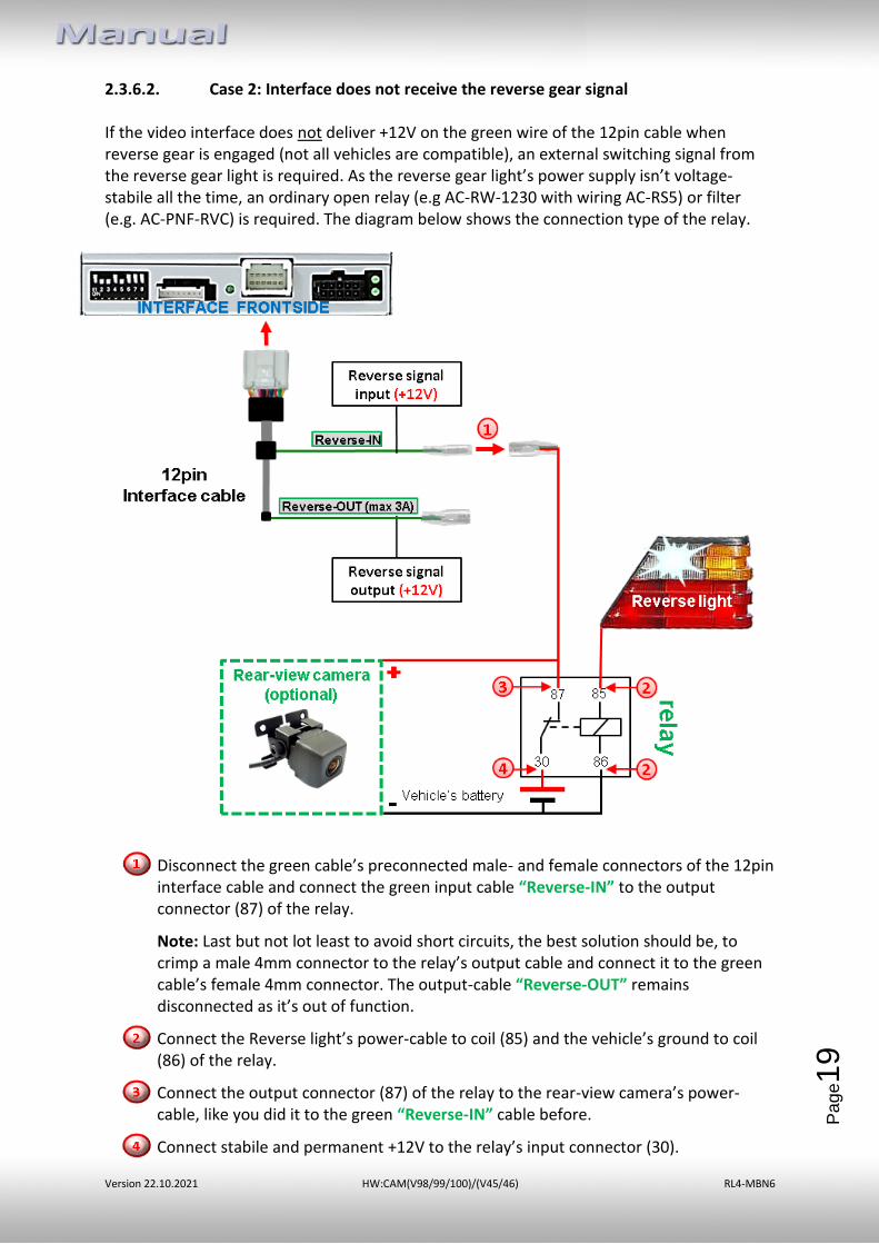
2.3.6.2. Case 2: Interface does not receive the reverse gear signal If the video interface does not deliver +12V on the green wire of the 12pin cable when reverse gear is engaged (not all vehicles are compatible), an external switching signal from the reverse gear light is required. As the reverse gear light’s power supply isn’t voltage-stabile all the time, an ordinary open relay (e.g AC-RW-1230 with wiring AC-RS5) or filter (e.g. AC-PNF-RVC) is required. The diagram below shows the connection type of the relay.
Disconnect the green cable’s preconnected male- and female connectors of the 12pin interface cable and connect the green input cable “Reverse-IN” to the output connector (87) of the relay.
Note: Last but not lot least to avoid short circuits, the best solution should be, to crimp a male 4mm connector to the relay’s output cable and connect it to the green cable’s female 4mm connector. The output-cable “Reverse-OUT” remains disconnected as it’s out of function.
Connect the Reverse light’s power-cable to coil (85) and the vehicle’s ground to coil (86) of the relay.
Connect the output connector (87) of the relay to the rear-view camera’s power-cable, like you did it to the green “Reverse-IN” cable before.
Connect stabile and permanent +12V to the relay’s input connector (30).
Version 22.10.2021 HW:CAM(V98/99/100)/(V45/46) RL4-MBN6
Pa
ge2
0
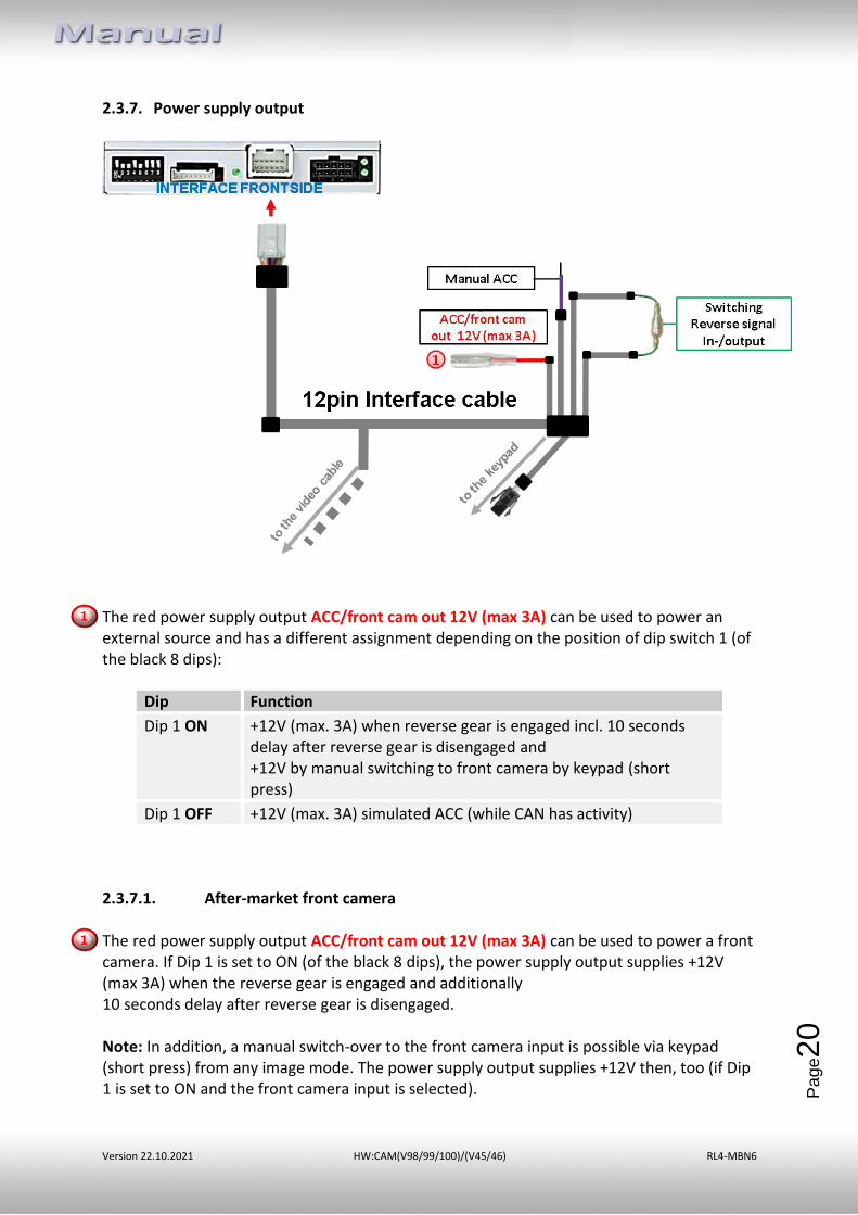
2.3.7. Power supply output
The red power supply output ACC/front cam out 12V (max 3A) can be used to power an external source and has a different assignment depending on the position of dip switch 1 (of the black 8 dips):
Dip Function
Dip 1 ON +12V (max. 3A) when reverse gear is engaged incl. 10 seconds delay after reverse gear is disengaged and +12V by manual switching to front camera by keypad (short press)
Dip 1 OFF +12V (max. 3A) simulated ACC (while CAN has activity) 2.3.7.1. After-market front camera The red power supply output ACC/front cam out 12V (max 3A) can be used to power a front camera. If Dip 1 is set to ON (of the black 8 dips), the power supply output supplies +12V (max 3A) when the reverse gear is engaged and additionally 10 seconds delay after reverse gear is disengaged. Note: In addition, a manual switch-over to the front camera input is possible via keypad (short press) from any image mode. The power supply output supplies +12V then, too (if Dip 1 is set to ON and the front camera input is selected).
Version 22.10.2021 HW:CAM(V98/99/100)/(V45/46) RL4-MBN6
Pa
ge2
1
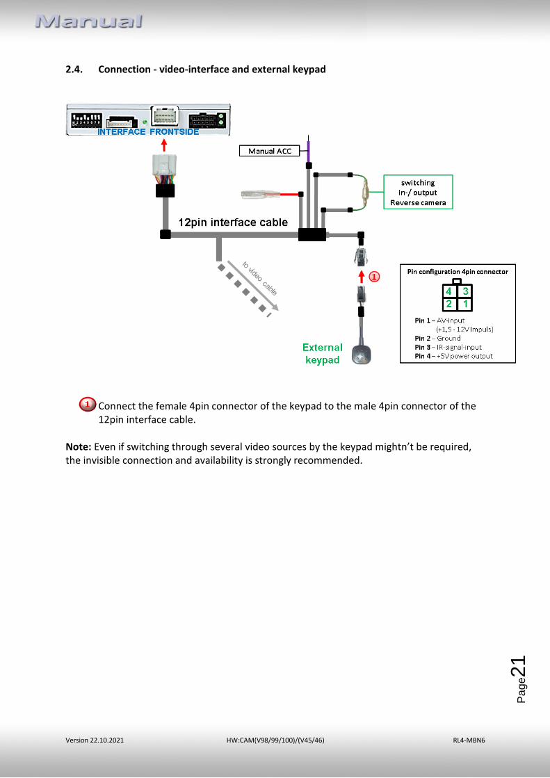
2.4. Connection - video-interface and external keypad
Connect the female 4pin connector of the keypad to the male 4pin connector of the 12pin interface cable.
Note: Even if switching through several video sources by the keypad mightn’t be required, the invisible connection and availability is strongly recommended.
Version 22.10.2021 HW:CAM(V98/99/100)/(V45/46) RL4-MBN6
Pa
ge2
2
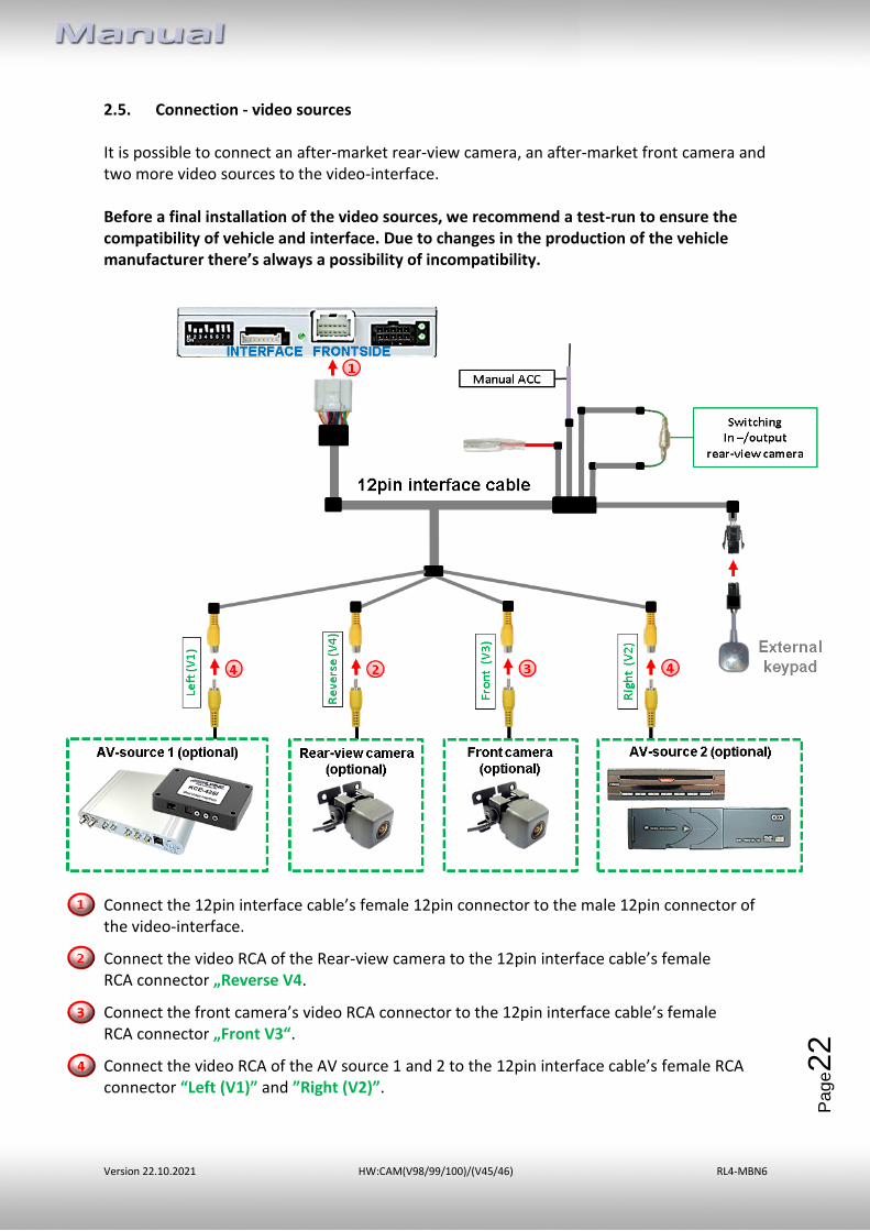
2.5. Connection - video sources It is possible to connect an after-market rear-view camera, an after-market front camera and two more video sources to the video-interface. Before a final installation of the video sources, we recommend a test-run to ensure the compatibility of vehicle and interface. Due to changes in the production of the vehicle manufacturer there’s always a possibility of incompatibility.
Connect the 12pin interface cable’s female 12pin connector to the male 12pin connector of the video-interface.
Connect the video RCA of the Rear-view camera to the 12pin interface cable’s female RCA connector „Reverse V4.
Connect the front camera’s video RCA connector to the 12pin interface cable’s female RCA connector „Front V3“.
Connect the video RCA of the AV source 1 and 2 to the 12pin interface cable’s female RCA connector “Left (V1)” and ”Right (V2)”.
Version 22.10.2021 HW:CAM(V98/99/100)/(V45/46) RL4-MBN6
Pa
ge2
3
2.6. Audio-insertion
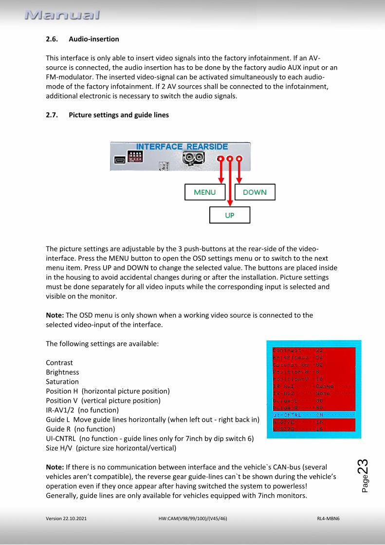
This interface is only able to insert video signals into the factory infotainment. If an AV-source is connected, the audio insertion has to be done by the factory audio AUX input or an FM-modulator. The inserted video-signal can be activated simultaneously to each audio-mode of the factory infotainment. If 2 AV sources shall be connected to the infotainment, additional electronic is necessary to switch the audio signals. 2.7. Picture settings and guide lines
The picture settings are adjustable by the 3 push-buttons at the rear-side of the video-interface. Press the MENU button to open the OSD settings menu or to switch to the next menu item. Press UP and DOWN to change the selected value. The buttons are placed inside in the housing to avoid accidental changes during or after the installation. Picture settings must be done separately for all video inputs while the corresponding input is selected and visible on the monitor. Note: The OSD menu is only shown when a working video source is connected to the selected video-input of the interface. The following settings are available: Contrast Brightness Saturation Position H (horizontal picture position) Position V (vertical picture position) IR-AV1/2 (no function) Guide L Move guide lines horizontally (when left out - right back in) Guide R (no function) UI-CNTRL (no function - guide lines only for 7inch by dip switch 6) Size H/V (picture size horizontal/vertical) Note: If there is no communication between interface and the vehicle`s CAN-bus (several vehicles aren’t compatible), the reverse gear guide-lines can`t be shown during the vehicle’s operation even if they once appear after having switched the system to powerless! Generally, guide lines are only available for vehicles equipped with 7inch monitors.
Version 22.10.2021 HW:CAM(V98/99/100)/(V45/46) RL4-MBN6
Pa
ge2
4
3. Interface operation
➢ Long press of keypad (2-3 seconds)
By long pressing the external keypad (2-3 seconds), the video interfaces witches the input from the factory video to the inserted video sources. If all inputs are activated by dip switch settings, the order is the following:
Factory video → Left (V1) → Right (V2) → factory video
Each long press will switch to the next enabled input. Inputs which are not enabled will be skipped.
Note: The interface switches after releasing the switch (after long pressure). ➢ Short press of keypad (only if DIP 1 is set to ON)
By short pressing the external keypad, the video interfaces witches from the factory video to the front camera input and with press-repeat back to factory video.
4. Specifications BATT/ACC range 7V - 25V Stand-by power drain 10mA Power 270mA @12V Video input 0.7V - 1V Video input formats NTSC/PAL Temperature range -40°C to +85°C Dimensions video-box 119 x 24 x 100 mm (W x H x D)
Version 22.10.2021 HW:CAM(V98/99/100)/(V45/46) RL4-MBN6
Pa
ge2
5
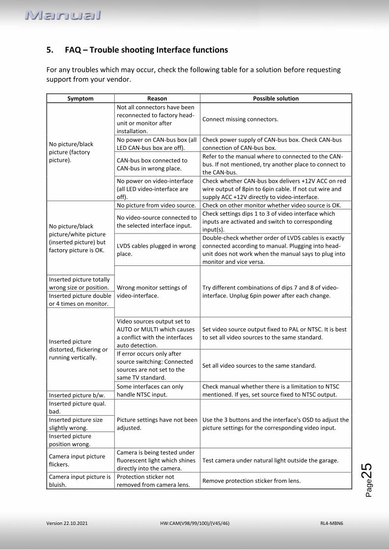
5. FAQ – Trouble shooting Interface functions For any troubles which may occur, check the following table for a solution before requesting support from your vendor.
Symptom Reason Possible solution
No picture/black picture (factory picture).
Not all connectors have been reconnected to factory head-unit or monitor after installation.
Connect missing connectors.
No power on CAN-bus box (all LED CAN-bus box are off).
Check power supply of CAN-bus box. Check CAN-bus connection of CAN-bus box.
CAN-bus box connected to CAN-bus in wrong place.
Refer to the manual where to connected to the CAN-bus. If not mentioned, try another place to connect to the CAN-bus.
No power on video-interface (all LED video-interface are off).
Check whether CAN-bus box delivers +12V ACC on red wire output of 8pin to 6pin cable. If not cut wire and supply ACC +12V directly to video-interface.
No picture/black picture/white picture (inserted picture) but factory picture is OK.
No picture from video source. Check on other monitor whether video source is OK.
No video-source connected to the selected interface input.
Check settings dips 1 to 3 of video interface which inputs are activated and switch to corresponding input(s).
LVDS cables plugged in wrong place.
Double-check whether order of LVDS cables is exactly connected according to manual. Plugging into head-unit does not work when the manual says to plug into monitor and vice versa.
Wrong monitor settings of video-interface.
Try different combinations of dips 7 and 8 of video-interface. Unplug 6pin power after each change.
Inserted picture totally wrong size or position.
Inserted picture double or 4 times on monitor.
Inserted picture distorted, flickering or running vertically.
Video sources output set to AUTO or MULTI which causes a conflict with the interfaces auto detection.
Set video source output fixed to PAL or NTSC. It is best to set all video sources to the same standard.
If error occurs only after source switching: Connected sources are not set to the same TV standard.
Set all video sources to the same standard.
Some interfaces can only handle NTSC input.
Check manual whether there is a limitation to NTSC mentioned. If yes, set source fixed to NTSC output. Inserted picture b/w.
Inserted picture qual. bad.
Picture settings have not been adjusted.
Use the 3 buttons and the interface's OSD to adjust the picture settings for the corresponding video input.
Inserted picture size slightly wrong.
Inserted picture position wrong.
Camera input picture flickers.
Camera is being tested under fluorescent light which shines directly into the camera.
Test camera under natural light outside the garage.
Camera input picture is bluish.
Protection sticker not removed from camera lens.
Remove protection sticker from lens.
Version 22.10.2021 HW:CAM(V98/99/100)/(V45/46) RL4-MBN6
Pa
ge2
6
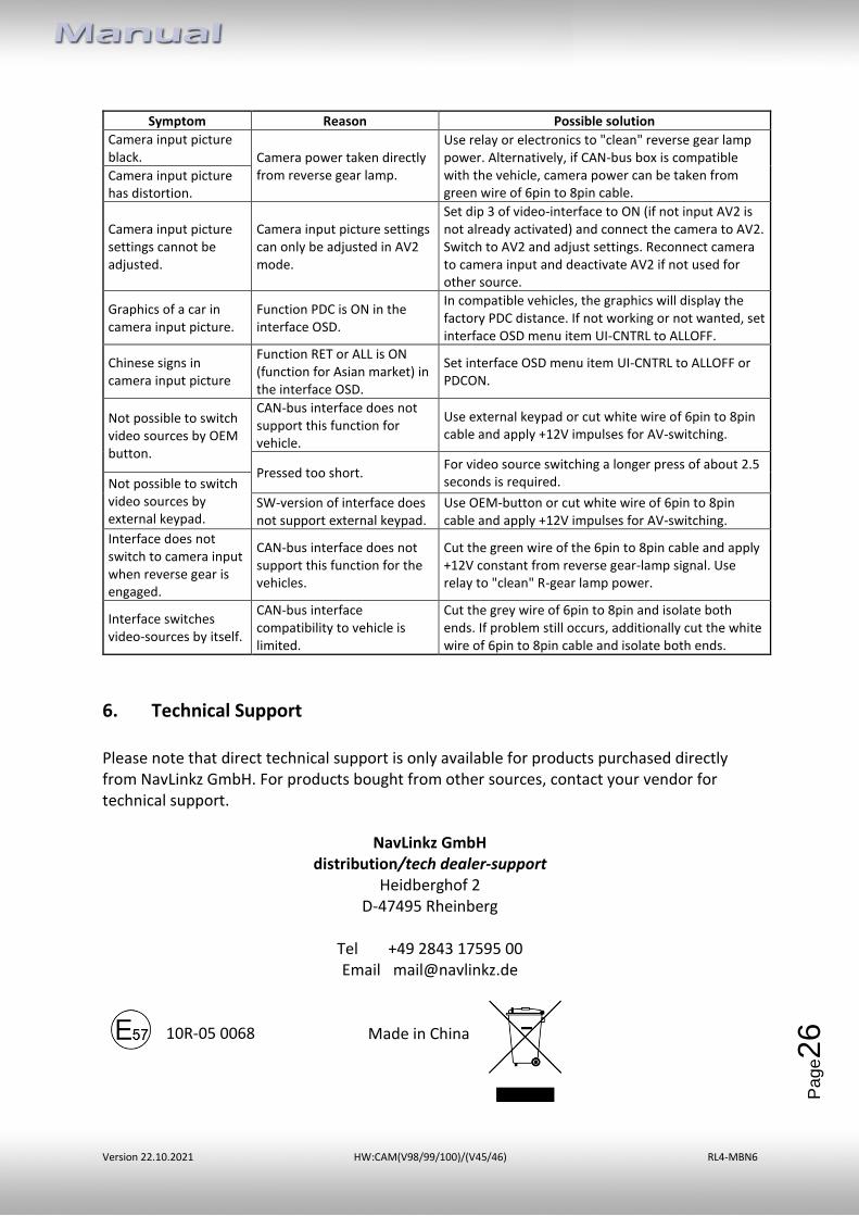
Symptom Reason Possible solution
Camera input picture black. Camera power taken directly
from reverse gear lamp.
Use relay or electronics to "clean" reverse gear lamp power. Alternatively, if CAN-bus box is compatible with the vehicle, camera power can be taken from green wire of 6pin to 8pin cable.
Camera input picture has distortion.
Camera input picture settings cannot be adjusted.
Camera input picture settings can only be adjusted in AV2 mode.
Set dip 3 of video-interface to ON (if not input AV2 is not already activated) and connect the camera to AV2. Switch to AV2 and adjust settings. Reconnect camera to camera input and deactivate AV2 if not used for other source.
Graphics of a car in camera input picture.
Function PDC is ON in the interface OSD.
In compatible vehicles, the graphics will display the factory PDC distance. If not working or not wanted, set interface OSD menu item UI-CNTRL to ALLOFF.
Chinese signs in camera input picture
Function RET or ALL is ON (function for Asian market) in the interface OSD.
Set interface OSD menu item UI-CNTRL to ALLOFF or PDCON.
Not possible to switch video sources by OEM button.
CAN-bus interface does not support this function for vehicle.
Use external keypad or cut white wire of 6pin to 8pin cable and apply +12V impulses for AV-switching.
Pressed too short. For video source switching a longer press of about 2.5 seconds is required. Not possible to switch
video sources by external keypad.
SW-version of interface does not support external keypad.
Use OEM-button or cut white wire of 6pin to 8pin cable and apply +12V impulses for AV-switching.
Interface does not switch to camera input when reverse gear is engaged.
CAN-bus interface does not support this function for the vehicles.
Cut the green wire of the 6pin to 8pin cable and apply +12V constant from reverse gear-lamp signal. Use relay to "clean" R-gear lamp power.
Interface switches video-sources by itself.
CAN-bus interface compatibility to vehicle is limited.
Cut the grey wire of 6pin to 8pin and isolate both ends. If problem still occurs, additionally cut the white wire of 6pin to 8pin cable and isolate both ends.
6. Technical Support Please note that direct technical support is only available for products purchased directly from NavLinkz GmbH. For products bought from other sources, contact your vendor for technical support.
NavLinkz GmbH distribution/tech dealer-support
Heidberghof 2 D-47495 Rheinberg
Tel +49 2843 17595 00 Email [email protected]
10R-05 0068
Made in China


![[en]=> P/N 327010xx (U277 70 10) - AMPIRE](https://img.pdfslide.net/doc/110x75/6262901d5b56083e9e3557a3/engt-pn-327010xx-u277-70-10-ampire.jpg)