Embed Size (px)
Citation preview

Video InterfaceJeffery Tsai
Sammy Sy
And pretty much everything else too….
CS 150 CHECKPOINT 3

The Project so far Controller Interface Audio Interface Video Interface Game Engine
Controller Block
Controller Interpreter
FSM
Memory Module
UARTAudio Module
Video Encoder

Checkpoint 3 Overview UART Serial Connection Learn Sammy’s GUI Memory Module (16x8 RAM) Simplified Game Engine Integration with previous
checkpoints

Overall State Machine
Poll the controller like normal and update the game state.
Update the video 4 times each second.
startinitialize
idle
process controller data
update game state
process events(play sounds)
video output

Serial Cable Protocol Regular Serial Cable Only need 2 pins since we only care
about sending data to the computer.• Pin 2 is to transmit (to the computer)• Pin 5 is ground• Pin 3 is there, but NOT USED
1 2 3 4 5
6 7 8 9
P5 – T1out
(on MAX233) GND

RS232 Waveforms
8 bits of data, 1 start bit, 1 stop bit Wire is normally high, and this
time, you MUST keep it high. Transmission rate = 57600bps
start bit MSB LSB
stop bit
start of tranmission
end of tranmission
17.36sTime

57,600bps?!?! You can’t get a 57.6kHz clock with a
conventional clock divider. (16,000,000/57,600 278)
Use the 16MHz clock, and pulse the output every 278 cycles.
By the way…..remember to use BUFG’s for ALL your clocks!

UART Universal Asynchronous Receiver
Transmitter. Since we don’t receive messages
from the computer, only the transmitter is needed.
Need a READY signal since it is critical that you try to send at the maximum rate. UART Transmitter
8data
transmit
serial outP37

Maxim Transceiver Actual serial connection is
inverted and is 12V. Maxim transceiver takes
care of everything. BUT BE CAREFUL!!! DO
NOT PLUG THE 12 VOLT END TO YOUR XILINX CHIP!
VCC
GND
GND
P37

Video Interpreter
This “DreamKatz” program draws the game screen on the computer monitor.
<demonstration>
mana[13:0]score[13:0]console
16x8 array of blocks[6:0]
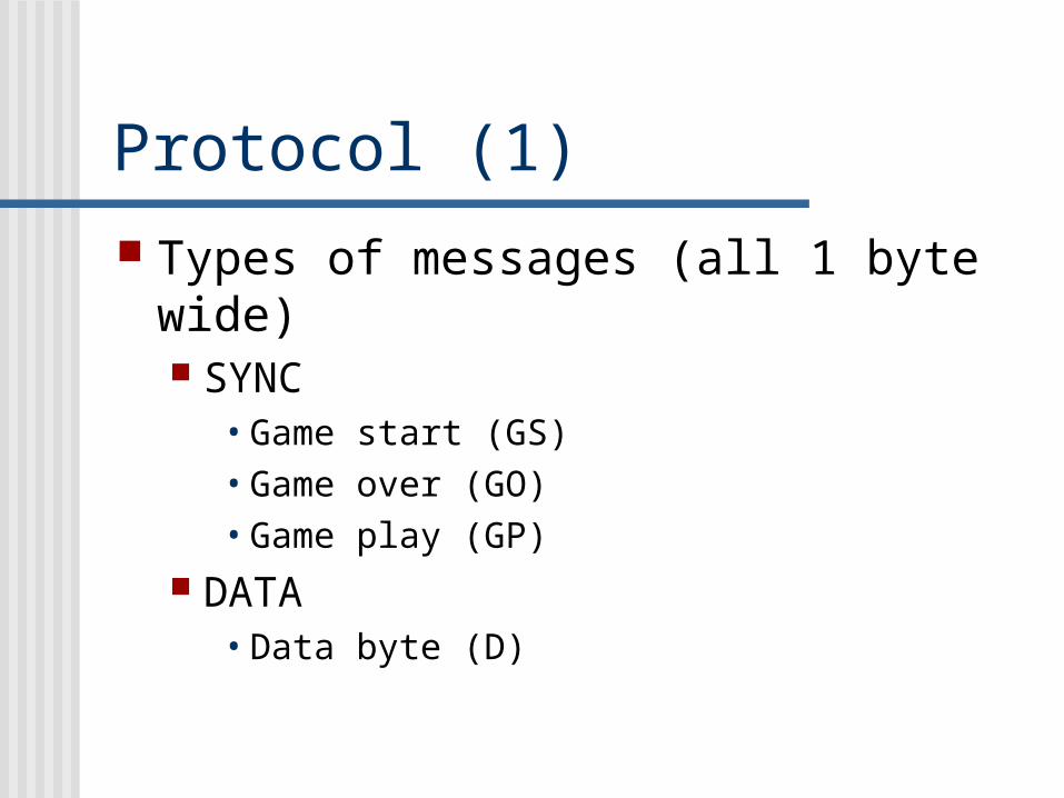
Protocol (1) Types of messages (all 1 byte wide)
SYNC• Game start (GS)• Game over (GO)• Game play (GP)
DATA• Data byte (D)

Protocol (2) Only 3 legal sequences, all preceded by a SYNC byte. Each sequence can be followed by another valid sequence.
Display game start screen• GS
Display game over screen with final score• GO, D, D
Display a new frame (grids + mana + score)• GP, D0, D1, D2, … D127, D, D, D, D
Reminder: GS = game start GO = game over GP = game play D = data byte

Protocol (3) Physical representation in bits
Game start = 1000 0001 Game over = 1000 0000 Game play = 1000 0010 Data = 0XXX XXXX
note: 0 <= Data <= 127 1XXX XX11 is always illegal

Protocol (4) Display game start screen
easy… just send GS byte Display game over screen and final
score1. GO: 1000 0000
2. D: 0,score[13:7]
3. D: 0,score[6:0]

Protocol (5) Display a frame
1. GP: 1000 00102. D0: 0, block0[6:0]3. D1: 0, block1[6:0]4. …5. DN: 0, blockN[6:0]6. …7. D127: 0, block127[6:0]8. D: 0, mana[13:7]9. D: 0, mana[6:0]10. D: 0, score[13:7]11. D: 0, score[6:0]
blockN[6:0] represents the type of image to display in the Nth block.
N=0 1 2 3 4 5 6 7 mana[13:0]8 score[13:0]16
24
32
40
48
56
64
72
80
88
96
104
112
120 121 122 123 124 125 126 127

Protocol Example Let’s display a frame with all white blocks
(white=000 0001), mana=7, score=128
GP: 1000 0010 (game play)D0: 0000 0001 (block0 = white) D1: 0000 0001 (block1 = white)…D127: 0000 0001 (block127 = white)D: 0000 0000 (manaHi = 000 0000)D: 0000 0111 (manaLo = 000 0111)D: 0000 0001 (scoreHi = 000 0001)D: 0000 0000 (scoreLo = 000 0000)

Killer checkpoint => Hints The master FSM is complicated, but
fortunately runs sequentially. Make sure you design it with Control and
Datapath in mind. You might find pseudocode helpful for
laying out the FSM’s and thus the control signals for the datapath. If pseudocode is good, datapath falls out naturally from it.

Pseudocode (1)MemoryModule GameState; // 16x8 RAM
/* Rotate all bits of GameState to left/right once */HandleLeftRight(bool left, bool right) { 8bitRegister tmp; for (I = 0; I < 16; I++) { tmp = GameState[I]; tmp = UniversalShiftRegister(tmp, left, right); GameState[I] = tmp; }}
/* Move all bits of GameState down once */HandleDown() { 8bitRegister tmp; for (I = 15; I >= 1; I--) { // process backwards! tmp = GameState[I-1]; GameState[I] = tmp; } GameState[0] = 0000 0000;}

Pseudocode (2)/* encode GameState into frame update message sequence */HandleEncode() { 8bitShiftRegister tmp; UART_Send(1000 0010); // sync game play byte for (I = 0; I < 16; I++) { tmp = GameState[I]; for (J = 0; J < 8; J++) { UART_SEND(0000 000,tmp[0]); // either white or black tmp = tmp >> 1; } } UART_SEND(0,MANA[13:7]); UART_SEND(0,MANA[6:0]); UART_SEND(0,SCORE[13:7]); UART_SEND(0,SCORE[6:0]);}

Pseudocode (3)/* Main loop * ENCODE_LIMIT = period of video refresh * FALL_LIMIT = period of blocks falling */HandleMain(bool left, bool right) { count = 0; while (1) { HandleLeftRight(left, right); // process left/right if (0 == (count % FALL_LIMIT)) { // process gravity HandleDown(); }
if (0 == (count % ENCODE_LIMIT)) { // process video HandleEncode(); }
count ++; }}

I don’t understand this pseudocode thing... Each subroutine is a mini-FSM that
has idle and active states. Calling a subroutine can be done by
sending a start pulse. When the subroutine returns, it
outputs a done pulse.
start
done
IDLE ACTIVE

In Conclusion… Checkpoint 3 is really long. BUT…don’t forget your midterm
next week. Good luck. Now Jeff and Sammy can
go sleep…