Embed Size (px)
Citation preview
Video System Manager Pro User Guide

Copyright © 2008 Philips Solid-State Lighting Solutions, Inc. All rights reserved.
Chromacore, Chromasic, CK, the CK logo, Color Kinetics, the Color Kinetics logo, ColorBlast, ColorBlaze, ColorBurst, ColorGraze,ColorPlay, ColorReach, DIMand, EssentialWhite, eW, iColor, iColor Cove, IntelliWhite, iW, iPlayer, Light Without Limits, Optibin, andPowercore are either registered trademarks or trademarks of Philips Solid-State Lighting Solutions, Inc. in the United States and/orother countries.
All other brand or product names are trademarks or registered trademarks of their respective owners.PUB-000199-01 R01

Contents
VSM Pro User Guide 2
Chapter 1 Welcome to Video System Manager Pro 4
Key Features 4About this Guide 5Related Documentation 6Contacting Philips Color Kinetics Technical Support 6
Chapter 2 Planning Stages 8
Planning the Layout 8Fixture Installation Considerations 9Power / Data Supply and Data Enabler Installation Considerations 9Planning Viewing Distances 9
Working with Video Resolutions 10Working with Video Sources 11Digital Media Source Examples 11Analog Media Source Examples 11System Configuration 12Testing a Video Display using VSM Pro 13Video Signal Correction and Network Bandwidth Fine-Tuning 13
VSM Pro Installation Example 14Display Details 14Network Details 15
Chapter 3 Prepare for the Installation 16VSM Pro Hardware Installation 16
Step 1: Confirm all components received 16Step 2: Mount in rack 17
Step 3: Connect the Network, Video, and Power Cables 18
Step 4: Turn on the Power 19System Requirements 19Network Address Configuration 19
Automatic IP Address Configuration for Windows® XP, Vista 20Static IP Address Configuration for Windows® XP, Vista 20Automatic IP Address Configuration for Mac OS X 21Static IP Address Configuration for Mac OS X 21
Video Management Tool Software Installation 22
Windows® Installation 22Mac OS X Installation 22
Chapter 4 VSM Pro Basic Operation 24Overview 24Using the Control Panel 24Control Panel Menus 25Accessing the VSM Pro User Interface 26
Connecting to the VSM Pro User Interface 26
Chapter 5 Overview 28What are Video Maps? 28Creating a Video Map 29Compatibility 29Working with Video Maps 29
View the Currently Loaded Map 29Manually Load a Video Map using the VSM Pro User Interface 30Automatically Load a Map to VSE Pro using VMT 31Download a Video Map from VSE Pro using VMT 31
Chapter 6 Selecting an Input 32Overview 32
Digital Inputs 32Analog Inputs 32Test Patterns 32
How an Input is Displayed, Based on Resolution 33Formatting Media Assets for Input 34
DVI or VGA Input 34Analog Input 34
Selecting an Input via the VSM Pro User Interface 35Selecting an Input via the hardware Control Panel 35
Chapter 7 Optimizing Video Output 36Overview 36
Video Output Enhancement Features 36Network Optimization Features 36Additional Features 36
Video Output Enhancement Features 37Gamma Correction 37Video Smoothing 39Interlacing (Analog Inputs only) 40Node Positions 41
Chapter 1
VSM Pro User Guide 3
Display Frame 42Adjusting Brightness 43Network Optimization Features 43Synchronization 43Frame Rate 44
Additional Features 45Log File 45File Backup 45
Appendices Appendix A 46 Test Patterns 46
Index Index 48

VSM Pro User Guide 4
Chapter 1
Introduction
Condé Nast Cafeteria New York, NY
Welcome to Video System Manager ProVideo System Manager Pro (VSM Pro) is an integrated hardware and software solution designed for video playback and visual effects display on Ethernet-based LED lighting installations.
• Video System Engine Pro (VSE Pro) controller device, the hardware component, processes and sends live video to installations comprising up to 250,000 LED nodes. This user guide provides complete information for configuring and using VSE Pro hardware.
• Video Management Tool (VMT) software, included with VSM Pro, creates video maps that associate source video pixels with their destination nodes in a lighting system. Refer to the Video Management Tool User Guide for detailed instructions on how to create a video map.
VSM Pro accepts direct input from external devices including media servers. To accommodate most sources, Philips offers two versions of hardware. The digital media version supports input via industry standard DVI and VGA connections; the analog version supports analog input via BNC composite and S-Video connections.
Key Features• Ease of use — VSM Pro connects directly to industry standard media sources for video
playback, visual effects editing, storage, scheduling, audio synchronization, and more.
• Compatible with wide-ranging lighting systems from Philips — Create a large-scale LED video installation without the cost of a conventional video wall.
• Hardware support for small, medium, and large-scale LED layouts — VSM Pro displays video on installations with up to 250,000 LED nodes.
Item Item Number Philips 12NC
VSM Pro DVI 103-000022-00 910503700325
VSM Pro Composite 103-000022-01 910503700455
Introduction
5 VSM Pro User Guide
• Ethernet control — VSM Pro operates on dedicated Ethernet networks, allowing you to focus on the creative aspects of lighting design and spend less time on setup.
• Flexible display capability — VSM Pro supports unconventional installation formats. Paired with flexible lighting systems from Philips, VSM Pro can display video on curved and three-dimensional surfaces.
• Seamless upgrade from version 1 — VSM Pro system offers full backwards compatibility with Video Management Tool version 1 map files.
• Onboard video source conversion — VSM Pro integrates all required video processing, eliminating the need for an external video conversion device.
About this GuideThis user guide offers the following information:
PlanningChapter 2 contains an overview of the workflow used to design a VSM Pro installation and includes a VSM Pro installation example.
Hardware and Software SetupChapter 3 provides step-by-step hardware and software installation instructions, steps for setting up a PC or Mac on the dedicated lighting network, and instructions for connecting to the VSM Pro User Interface.
Basic OperationsChapter 4 covers the hardware Control Panel and the VSM Pro User Interface.
Working with VMT MapsChapter 5 has instructions for downloading and using VMT video maps.
Selecting InputsVSM Pro accepts multiple video input types. Chapter 6 covers how to select a video input or use a built-in test pattern.
Optimizing Video Output Chapter 7 covers the advanced features used to optimize a source video signal and fine-tune video output based on network bandwidth.
Reference For quick reference, Appendix A lists information including built-in test patterns.
Chapter 1
VSM Pro User Guide 6
Related Documentation• The latest VSM Pro documentation is available on the web at: www.colorkinetics.com/ls/
controllers/vsmpro/. You can also download documentation directly from the VSM Pro User Interface, using a PC or Mac installed on your dedicated lighting network (enter 10.1.3.101 in a web browser to connect with the VSM Pro User Interface).
• To support large-scale installation, VSM Pro uses video maps rather than DMX channels to send data to the LED nodes in your installation. Refer to the Video Management Tool User Guide for detailed instructions on how to create a video map.
• Lighting system specification sheets, installation instructions and product guides are available from the web at: http://www.colorkinetics.com/support/userguides/
• VSM Pro accommodates a variety of lighting network designs by supporting both low-voltage lighting fixtures and Powercore® fixtures:
– Powercore fixtures work with Ethernet Data Enablers. Powercore fixtures perform onboard power processing and receive Ethernet data via the Data Enablers.
– Low-voltage fixtures work in unison with Ethernet Power / Data Supplies. Ethernet Power / Data Supplies blend power processing with data transmission capabilities.
Power / Data Supply and Data Enabler specification sheets and installation instructions are available from the web at: http://www.colorkinetics.com/ls/pds/.
• Detailed wiring diagrams are available from the web at: http://www.colorkinetics.com/support/wiring/ls_prod.html.
You will need Adobe Reader® to view PDF documentation. You can download the current version of Adobe Reader from the web at: http://www.adobe.com/products/acrobat/.
Contacting Philips Color Kinetics Technical SupportContact Philips Color Kinetics technical support for assistance with VSM Pro:
Phone888.Full.RGB, press option number 3 (toll free US, Canada and Mexico)617.423.9999, press option number 3 (toll worldwide)
Webwww.colorkinetics.com/support

Introduction
7 VSM Pro User Guide
VSM Pro User Guide 8
Chapter 2
System Overview
This chapter describes the recommended planning stages of a VSM Pro implementation and includes an example of a completed installation.
Planning Stages
Planning the LayoutVSM Pro is compatible with wide-ranging LED lighting systems from Philips, including direct view, linear, and surface-washing fixtures.
Video installations typically use flexible and rigid linear direct view systems:
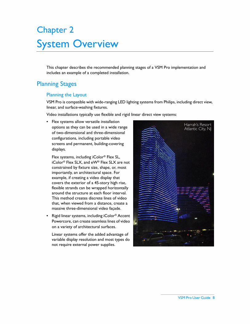
• Flex systems allow versatile installation options as they can be used in a wide range of two-dimensional and three-dimensional configurations, including portable video screens and permanent, building-covering displays.
Flex systems, including iColor® Flex SL, iColor® Flex SLX, and eW® Flex SLX are not constrained by fixture size, shape, or, most importantly, an architectural space. For example, if creating a video display that covers the exterior of a 45-story high rise, flexible strands can be wrapped horizontally around the structure at each floor interval. This method creates discrete lines of video that, when viewed from a distance, create a massive three-dimensional video façade.
• Rigid linear systems, including iColor® Accent Powercore, can create seamless lines of video on a variety of architectural surfaces.
Linear systems offer the added advantage of variable display resolution and most types do not require external power supplies.
Harrah’s ResortAtlantic City, NJ

System Overview
9 VSM Pro User Guide
Fixture Installation ConsiderationsVSM Pro accommodates a vast range of two-dimensional and three-dimensional installations, including unconventional configurations. For example, when mounted to cloth, flexible LED strands form a portable, hanging video screen that can be folded up and packed in a matter of minutes. For permanent installations, flexible strands can be intertwined through any grid material mounted to the exterior of a building. Similarly, theatrical applications could use three-dimensional shapes created from wire mesh, with strands of flexible fixtures woven through the shapes to create a unique video medium. Keep these options in mind when planning your installation.
Power / Data Supply and Data Enabler Installation ConsiderationsVSE Pro is an Ethernet-based controller. During installation, each PDS and Data Enabler in the lighting network receives an IP address. Use a logical IP address naming convention for each device. For example, create IP addresses based on the floor and wing of a building. Record the IP address and physical location of each device for future reference.
Planning Viewing DistancesThe LED nodes in an installation function as video pixels. As part of the planning process, design a fixture layout that places nodes close enough together to accommodate video at acceptable minimum and maximum viewing distances.
Images on an LED video display appear to be sharper to the human eye as the distance to the display increases. Likewise, images appear less visible as the distance decreases. The spacing, or pixel pitch, between LED nodes determines the minimum and maximum viewing distances for discernible video output.
Note: The viewing calculations and examples listed below are general guidelines based on video displays using grids of evenly spaced LED nodes. VSM Pro implementations are not constrained to grid formats. For these implementations, or for designs where the acceptable level of discernible video may be more or less demanding, contact Philips Color Kinetics Application Engineering Services for assistance.
• To determine the minimum viewing distance, multiply the node pitch by 100 distance units. For example, if the node pitch is 50 mm, the minimum viewing distance is 5 m.
• To determine the maximum viewing distance for discernible video, multiply the screen height by 20 distance units. For example, if the screen height is 20 m, then the maximum viewing distance for recognizable video is 400 m.
• LED screens are still visible beyond the maximum viewing distance for discernible video. To determine the maximum viewing distance that still creates visual impact, multiply the screen height by 50 units. For example, a 20 m high screen will continue to create visual impact at 1000 m.
Pixel Pitch (e.g. iColor Flex SL)
Chapter 2
VSM Pro User Guide 10
Methods for Increasing Pixel PitchDesigning a layout with overlapping fixtures is a common technique for increasing pixel pitch. For example, to create a dense line of nodes, place multiple parallel runs of flexible strands close to each other vertically, with a slight horizontal offset between the nodes.
Using made-to-order fixtures is another method for increasing pixel pitch. Philips offers custom lengths and node spacing for certain flexible fixtures, in many cases at no additional cost.
Working with Video Resolutions
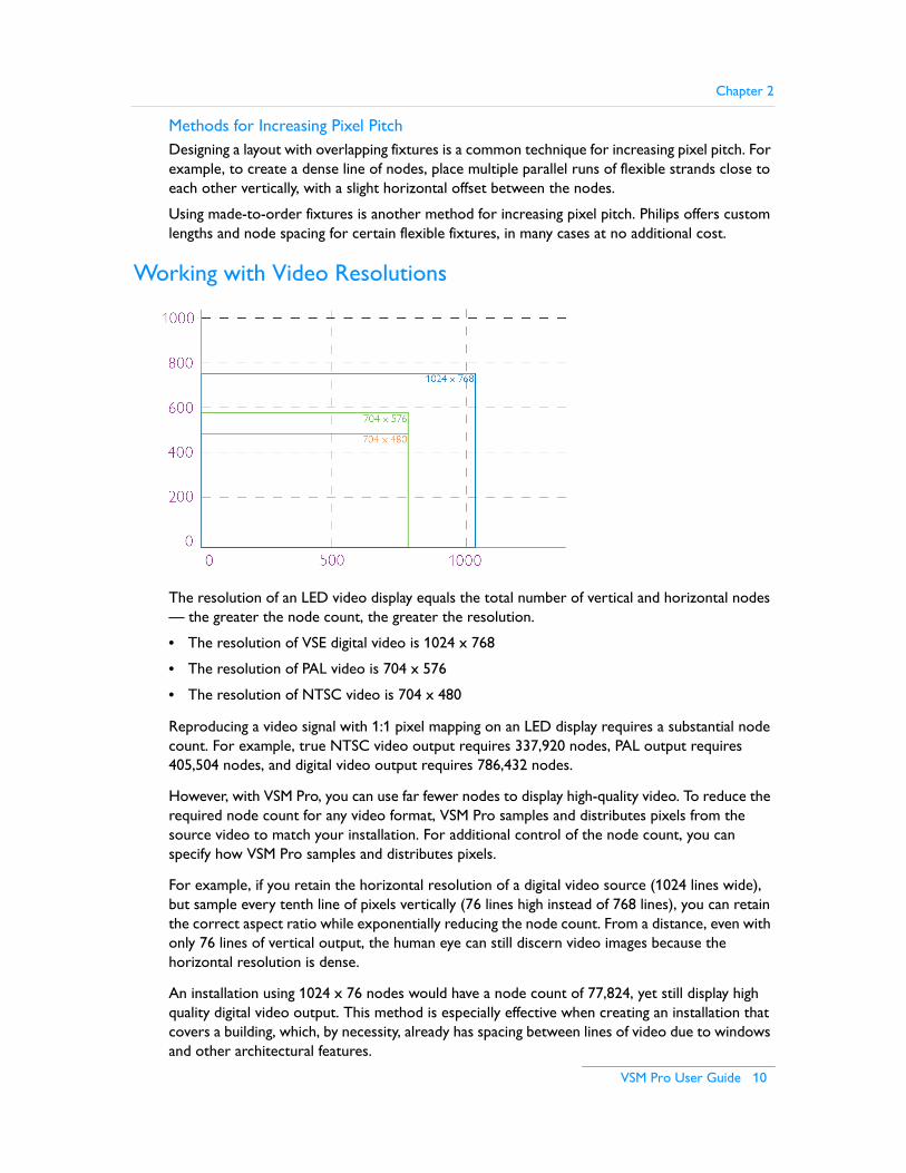
The resolution of an LED video display equals the total number of vertical and horizontal nodes — the greater the node count, the greater the resolution.
• The resolution of VSE digital video is 1024 x 768
• The resolution of PAL video is 704 x 576
• The resolution of NTSC video is 704 x 480
Reproducing a video signal with 1:1 pixel mapping on an LED display requires a substantial node count. For example, true NTSC video output requires 337,920 nodes, PAL output requires 405,504 nodes, and digital video output requires 786,432 nodes.
However, with VSM Pro, you can use far fewer nodes to display high-quality video. To reduce the required node count for any video format, VSM Pro samples and distributes pixels from the source video to match your installation. For additional control of the node count, you can specify how VSM Pro samples and distributes pixels.
For example, if you retain the horizontal resolution of a digital video source (1024 lines wide), but sample every tenth line of pixels vertically (76 lines high instead of 768 lines), you can retain the correct aspect ratio while exponentially reducing the node count. From a distance, even with only 76 lines of vertical output, the human eye can still discern video images because the horizontal resolution is dense.
An installation using 1024 x 76 nodes would have a node count of 77,824, yet still display high quality digital video output. This method is especially effective when creating an installation that covers a building, which, by necessity, already has spacing between lines of video due to windows and other architectural features.

System Overview
11 VSM Pro User Guide
Working with Video SourcesVSM Pro does not store video files — the content is sent to VSM Pro from a media source. To accommodate most media source types, Philips offers two versions of hardware: the digital version accepts video input from media sources via DVI or VGA cable, and the analog version accepts video input via BNC composite or S-Video cable.
Digital Media Source Examples• Digital media servers
• Personal computers or workstations with digital output cards
Analog Media Source Examples• Personal computers or workstations with analog output cards
• DVD players
• Camcorders
Digital media servers are the industry standard media source typically used with VSM Pro. Digital media servers provide video playback features, scheduling, visual effects editing, file storage, and integration with other devices.
Analog video sources provide some or all of the same features as digital sources, with reduced pixel resolution. Analog sources are typically used for displaying abstract effects, rather than video, on an LED installation (see the cover photo).
Source Media FormattingMedia assets require formatting prior to use with VSM Pro. For example, a 2K digital video source file (2048 x 1080 pixel resolution) requires downsampling to 1024 x 768 for display on a VSM Pro digital system. Additionally, given the flexibility of VSM Pro installations, video is not necessarily displayed on a rectangular screen; the source media may require additional processing to match the unconventional layout of an installation. For example, when displaying video on a four-sided high rise building, the media content requires formatting into four unique segments, one for each side of the structure.
Note: For the most streamlined workflow, especially when creating large-scale LED displays, use a media server or media formatting workstation to optimize content before sending it to VSM Pro.

Chapter 2
VSM Pro User Guide 12
System ConfigurationVSM Pro communicates with lighting components via KiNET™ Ethernet, the network protocol engineered by Philips Color Kinetics specifically for lighting control in large-scale installations. KiNET is fully compatible with all Ethernet hardware.
Media Source LANThe hardware device supplying source media — typically a media server — operates on an Ethernet network isolated from the VSE Pro controller. The media device connects to VSE Pro via DVI / VGA cable or BNC / S-video cable.
Lighting Network LANThe VSE Pro controller functions as the core component of the lighting system network, delivering up to 60 frames of video per second to as many as 250,000 LED nodes. Additionally, the VSE Pro functions as a dynamic address server assigning an IP address to any connected computer. To ensure optimal network performance and unencumbered IP addressing, hardware must be set up on a dedicated Ethernet LAN (Local Area Network).
VSM Pro supports an Ethernet LAN up to three Gigabit switches deep. The maximum specification for a CAT-5e cable run is 328 ft (100 m). However, fiber optic cabling is preferred for most installation configurations, when connecting the server room to a remote cabinet, for example.
Note: Philips recommends that you consult a third-party network consultant regarding specifics of your network components and configurations.
Low VoltageFixtures
PowercoreFixtures
PC or Mac
GigabitEthernetSwitch
Low VoltageFixtures
PowercoreFixtures
VSE ProLighting Network Dedicated LAN
EthernetPower / DataSupply
EthernetPower / DataSupply
EthernetData Enabler
EthernetData Enabler
GigabitEthernetSwitch
GigabitEthernetSwitch
Media Server
Video Map
PlaybackMedia Source LAN
System Overview
13 VSM Pro User Guide
VSM Pro accommodates a variety of lighting network designs by supporting both low-voltage lighting fixtures and Powercore® fixtures.
• Low-voltage fixtures work in unison with Ethernet Power / Data Supplies. Ethernet Power / Data Supplies blend power processing with data transmission capabilities.
• Powercore fixtures work with Ethernet Data Enablers. Powercore fixtures perform onboard power processing and receive Ethernet data via the Data Enablers.
About Video MapsA video map allows VSM Pro to map the LED nodes in an installation back to individual pixels in the source media. VMT software, installed on a computer connected to the dedicated LAN, allows you to create and upload video maps.
Note: Once configured with an IP address, the computer can upload VMT video maps and connect to the VSM Pro User Interface. The computer can be disconnected when not in use for map creation or tasks via the User Interface.
Testing a Video Display using VSM ProVSM Pro has multiple built-in test patterns, both static images and moving images. Following installation, you can use the test patterns to verify that fixtures and nodes are functioning, test a video map, isolate issues, and identify any network bandwidth issues that could slow output.
Additionally, the Display Frame feature allows capture of a single video frame, enabling you to preview video output.
Video Signal Correction and Network Bandwidth Fine-TuningWhen working with large-scale lighting networks, you may need to optimize the video output from VSM Pro. VSM Pro offers the following video output processing features:
• Video color intensity correction including adjustable gamma, black level, and white level settings
• Noise reduction
• Node distribution
• Frame rate control
• Packet synchronization
• Field interlacing pattern options
Chapter 2
VSM Pro User Guide 14
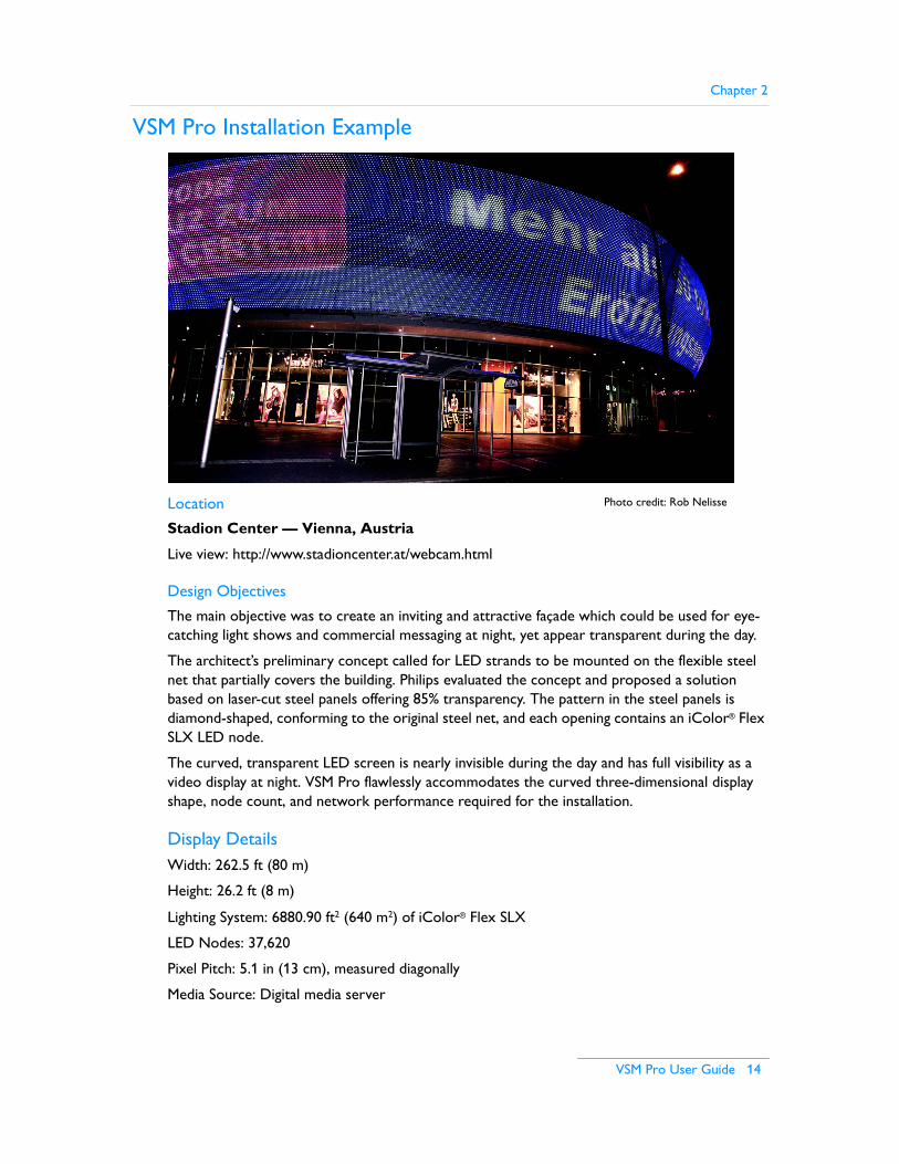
VSM Pro Installation Example
Location
Stadion Center — Vienna, Austria
Live view: http://www.stadioncenter.at/webcam.html
Design Objectives
The main objective was to create an inviting and attractive façade which could be used for eye-catching light shows and commercial messaging at night, yet appear transparent during the day.
The architect’s preliminary concept called for LED strands to be mounted on the flexible steel net that partially covers the building. Philips evaluated the concept and proposed a solution based on laser-cut steel panels offering 85% transparency. The pattern in the steel panels is diamond-shaped, conforming to the original steel net, and each opening contains an iColor® Flex SLX LED node.
The curved, transparent LED screen is nearly invisible during the day and has full visibility as a video display at night. VSM Pro flawlessly accommodates the curved three-dimensional display shape, node count, and network performance required for the installation.
Display DetailsWidth: 262.5 ft (80 m)
Height: 26.2 ft (8 m)
Lighting System: 6880.90 ft2 (640 m2) of iColor® Flex SLX
LED Nodes: 37,620
Pixel Pitch: 5.1 in (13 cm), measured diagonally
Media Source: Digital media server
Photo credit: Rob Nelisse

System Overview
15 VSM Pro User Guide
Network Details• An indoor server room contains the VSE Pro controller, a media server, and one Gigabit
Ethernet switch
• Fiber-optic cabling runs from the server room to 18 temperature-controlled outdoor cabinets, each containing one Gigabit Ethernet switch and seven or eight sPDS-480ca, Power / Data Supplies
• CAT-5e cables connect the switch to the Power / Data Supplies within each cabinet
• 60 – 64 strands of iColor® Flex SLX run from each cabinet to the display grid
• The strands are woven into the display grid in alternating fashion, from the top and from the bottom
Fiber optic cable
1 GbitSwitch
30 over
32.8 ft(10 m)
0 ft(0 m)
65.6 ft(20 m)
98.4 ft(30 m)
131 ft(40 m)
37,620 LED nodes
Fiber optic cable
164 ft(50 m)
197 ft(60 m)
230 ft(70 m)
262 ft(80 m)
(8)sPDS480 ca
1 GbitSwitch
(8)sPDS480 ca
1 GbitSwitch
(8)sPDS480 ca
1 GbitSwitch
(8)sPDS480 ca
1 GbitSwitch
(8)sPDS480 ca
1 GbitSwitch
(8)sPDS480 ca
1 GbitSwitch
(8)sPDS480 ca
1 GbitSwitch
(8)sPDS480 ca
1 GbitSwitch
(8)sPDS480 ca
1 GbitSwitch
(8)sPDS480 ca
1 GbitSwitch
(8)sPDS480 ca
1 GbitSwitch
(8)sPDS480 ca
1 GbitSwitch
(8)sPDS480 ca
(3)1 GbitSwitch
(7)sPDS480 ca
1 GbitSwitch
(8)sPDS480 ca
1 GbitSwitch
(8)sPDS480 ca
1 GbitSwitch
(8)sPDS480 ca
1 GbitSwitch
(8)sPDS480 ca
32 over
30 under
30 over
32 under
30 over
32 under
30 over
32 under
30 over
32 under
30 over
32 under
30 over
32 under
30 over
32 under
30 over
32 under
30 over
32 under
30 over
32 under
28 over
32 under
32 over
28 under
32 over
32 under
32 over
32 under
32 over
32 under
30 over
32 under
30 under
1 GbitSwitch
VSE Pro
26.3 ft(8 m)

VSM Pro User Guide 16
Chapter 3
Hardware and Software Installation
Prepare for the Installation1. Verify that the lighting system network will be installed on a dedicated LAN using Gigabit
Ethernet switches.
2. Install and configure all lighting fixtures, Ethernet Power / Data Supplies, and Data Enabler devices. Refer to the appropriate documentation for installation and configuration details.
3. Certain Gigabit Ethernet switch settings suppress a single device from monopolizing network bandwidth. Since the VSE Pro controller will be the primary device driving network communications, and the network will be isolated from outside network traffic, the following switch features can be disabled:
– Back pressure– Packet filtering– Broadcast storm control– Firewall protection
4. Prepare the source video. For best results, optimize the source video content using external media tools prior to sending the video signal to VSM Pro.
VSM Pro Hardware Installation
Step 1: Confirm all components received
Take a moment to confirm you have received these components:
• VSE Pro controller
• Power cord
• Composite Video breakout cable (Composite Video system version only)
DVI System
Composite Video System
Hardware and Software Installation
17 VSM Pro User Guide
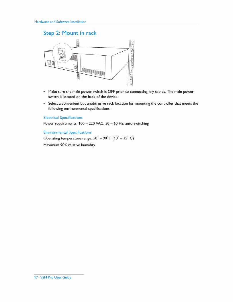
Step 2: Mount in rack
• Make sure the main power switch is OFF prior to connecting any cables. The main power switch is located on the back of the device
• Select a convenient but unobtrusive rack location for mounting the controller that meets the following environmental specifications:
Electrical SpecificationsPower requirements: 100 – 220 VAC, 50 – 60 Hz, auto-switching
Environmental SpecificationsOperating temperature range: 50˚ – 90˚ F (10˚ – 35˚ C)
Maximum 90% relative humidity
ETHERNET

Chapter 3
VSM Pro User Guide 18
Step 3: Connect the Network, Video, and Power Cables
• Connect a CAT-5e Ethernet cable from the lighting system network to the Ethernet input on the back of the controller.
• Connect the source video input cable:.
– If connecting to a digital media source, attach a user-supplied DVI or VGA cable from the source device to the appropriate port on the back panel of the VSE Pro.
– If working with an analog media source, first attach the provided Composite Video breakout cable to the Composite port on the back panel of the VSE Pro, then connect a user-supplied BNC Composite Video cable or S-Video cable to the appropriate plug on the breakout cable. Note that only the BNC Composite Video and S-Video plugs on the breakout cable are active.
• Connect the provided power cable.
VGA In DVI In
ETHERNET
MASTERON / OFF
DVI input
Composite In
ETHERNET
MASTERON / OFF
Composite Video input
Hardware and Software Installation
19 VSM Pro User Guide
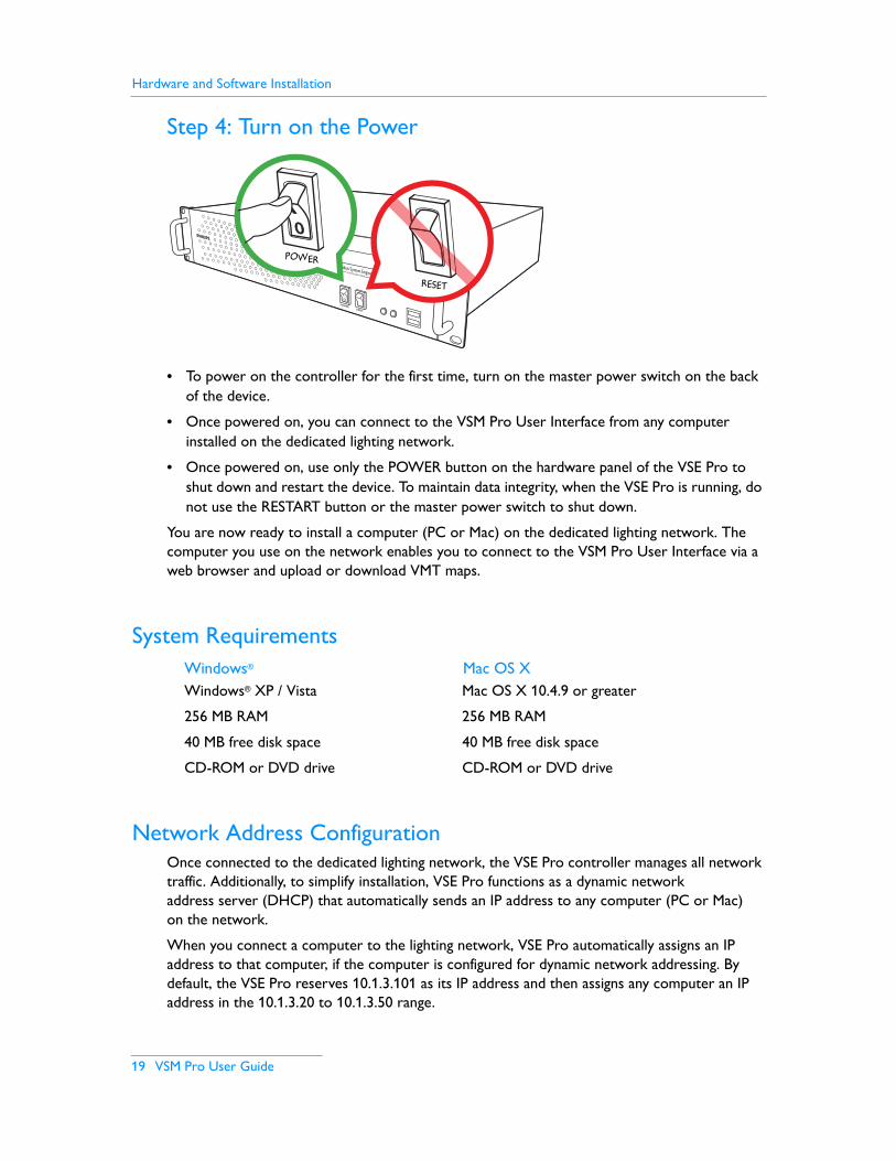
Step 4: Turn on the Power
• To power on the controller for the first time, turn on the master power switch on the back of the device.
• Once powered on, you can connect to the VSM Pro User Interface from any computer installed on the dedicated lighting network.
• Once powered on, use only the POWER button on the hardware panel of the VSE Pro to shut down and restart the device. To maintain data integrity, when the VSE Pro is running, do not use the RESTART button or the master power switch to shut down.
You are now ready to install a computer (PC or Mac) on the dedicated lighting network. The computer you use on the network enables you to connect to the VSM Pro User Interface via a web browser and upload or download VMT maps.
System RequirementsWindows® Mac OS XWindows® XP / Vista Mac OS X 10.4.9 or greater
256 MB RAM 256 MB RAM
40 MB free disk space 40 MB free disk space
CD-ROM or DVD drive CD-ROM or DVD drive
Network Address ConfigurationOnce connected to the dedicated lighting network, the VSE Pro controller manages all network traffic. Additionally, to simplify installation, VSE Pro functions as a dynamic network address server (DHCP) that automatically sends an IP address to any computer (PC or Mac) on the network.
When you connect a computer to the lighting network, VSE Pro automatically assigns an IP address to that computer, if the computer is configured for dynamic network addressing. By default, the VSE Pro reserves 10.1.3.101 as its IP address and then assigns any computer an IP address in the 10.1.3.20 to 10.1.3.50 range.
POWERRESET
POWER
RESET
Chapter 3
VSM Pro User Guide 20
Once addressed, a computer can connect to the VSM Pro User Interface when you enter 10.1.3.101 in a web browser.
If your computer is set up for dynamic addressing, but you cannot connect to the VSM Pro User Interface, the issue may be that your computer has multiple network adapters, for example a standard network adapter and a wireless adapter. Change your network preferences to select the device with the 10.1.3.X IP address. Refer to your operating system user documentation for details on changing network preferences, as needed.
If your computer is not set up for dynamic network addressing, use the following steps tore-configure the network address setup for compatibility with VSM Pro. You can reconfigure for automatic IP addressing, or set a static IP address:
Automatic IP Address Configuration for Windows® XP, Vista1. From the Start menu, select Control Panel. In the Control Panel, double-click the
Network Connections icon.
2. Double-click the Local Area Connection icon.
3. In the Local Area Connection Status window, click Properties.
4. In the Area Connection Status window, click to highlight Internet Protocol (TCP/IP), then click Properties.
5. If an IP or DNS address is present in the Internet Protocol (TCP/IP) Properties dialog box, record these numbers, in case you need them for future use.
6. Click the radio button to select Obtain IP Address Automatically and Obtain DNS Server Address Automatically. Click OK.
7. To turn off firewall protection, click the Advanced tab from the Local Area Connection properties window. Deselect Protect My Computer and Network by Limiting or Preventing Access to this Computer From the Internet.
8. Click OK to return to the Local Area Connection Status window, then close.
9. Restart your computer to accept the new network settings.
10.To verify the automatic IP configuration from VSE Pro, select Start > All Programs > Accessories > Command Prompt. At the prompt, enter IPCONFIG and press [Enter]. The IP address should be within the range of 10.1.3.20 to 10.1.3.50. The Subnet Mask should be 255.0.0.0.
Static IP Address Configuration for Windows® XP, Vista1. From the Start menu, select Control Panel. In the Control Panel, double-click the
Network Connections icon.
2. Double-click the Local Area Connection icon.
3. In the Local Area Connection Status window, click Properties.
4. In the Area Connection Status window, click to highlight Internet Protocol (TCP/IP), then click Properties.
5. If an IP or DNS address is present in the Internet Protocol (TCP/IP) Properties dialog box, record these numbers, in case you need them for future use.
Hardware and Software Installation
21 VSM Pro User Guide
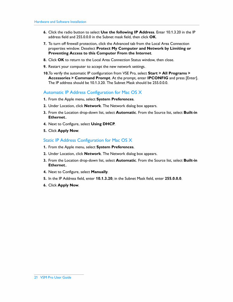
6. Click the radio button to select Use the following IP Address. Enter 10.1.3.20 in the IP address field and 255.0.0.0 in the Subnet mask field, then click OK.
7. To turn off firewall protection, click the Advanced tab from the Local Area Connection properties window. Deselect Protect My Computer and Network by Limiting or Preventing Access to this Computer From the Internet.
8. Click OK to return to the Local Area Connection Status window, then close.
9. Restart your computer to accept the new network settings.
10.To verify the automatic IP configuration from VSE Pro, select Start > All Programs > Accessories > Command Prompt. At the prompt, enter IPCONFIG and press [Enter]. The IP address should be 10.1.3.20. The Subnet Mask should be 255.0.0.0.
Automatic IP Address Configuration for Mac OS X1. From the Apple menu, select System Preferences.
2. Under Location, click Network. The Network dialog box appears.
3. From the Location drop-down list, select Automatic. From the Source list, select Built-in Ethernet..
4. Next to Configure, select Using DHCP.
5. Click Apply Now.
Static IP Address Configuration for Mac OS X1. From the Apple menu, select System Preferences.
2. Under Location, click Network. The Network dialog box appears.
3. From the Location drop-down list, select Automatic. From the Source list, select Built-in Ethernet..
4. Next to Configure, select Manually.
5. In the IP Address field, enter 10.1.3.20; in the Subnet Mask field, enter 255.0.0.0.
6. Click Apply Now.

Chapter 3
VSM Pro User Guide 22
Video Management Tool Software InstallationVMT software comes factory loaded on the VSM Pro controller. To download software to any computer on the dedicated lighting network, connect to the VSE Pro User Interface by entering 10.1.3.101 in a web browser, then click on the software download link located on the main screen.
Windows® Installation1. In the VSE Pro User Interface main screen, click Video Management Tool v2.0
Windows Installer link.
2. The Video Management Tool v2.0 Setup Wizard window appears. Click Next to begin the installation.
3. After reading the license agreement, select I Agree to consent to the terms of the license agreement, then click Next to continue.
4. When the Select Installation Folder window appears, accept the default location, or click Browse to select a folder. Click Next to continue.
5. At the Confirm Selection window, click Next to start installation.
6. The Installation Complete window appears. Click Close to exit the wizard.
Mac OS X Installation1. In the VSE Pro User Interface main screen, click the Video Management Tool v2.0 Mac
OS X Installer link.
2. If your browser does not automatically mount the disk image, double-click the downloaded file to open (mount) it. This creates a mounted disk image icon on the desktop and opens a disk-image folder window containing the VMT2 application icon.
3. Drag the VMT2 application icon to a Hard Disk location such as the Applications folder. Close the disk-image folder window. Note: Be sure to drag the VMT2 application out of the opened disk image window and onto your Hard Disk before running it. Do not double click the VMT2 icon in the disk image.
4. Select the mounted disk image by clicking it once.
5. From the File menu, select Eject VMT2. Alternately, you can control-click the mounted disk image icon and choose Eject.
6. Drag the .DMG file to the trash (unless you want to keep it as a backup).

Hardware and Software Installation
23 VSM Pro User Guide

VSM Pro User Guide 24
Chapter 4
VSM Pro Basic OperationOverview
VSM Pro offers two means of operation: the hardware Control Panel and the software User Interface. With the exception of the Brightness menu, all hardware-accessible menu options are available via the User Interface.
This chapter describes how to properly power On and power Off hardware and access the menus in both interfaces. Chapters 5 – 7 describe using the menu options to configure VSM Pro.
Using the Control Panel
The hardware Control Panel of the VSE Pro controller houses the following:
LCD — Displays startup messages, operational status, and menus.
Menu navigation buttons — Access menus, select options, and view information including the map file name, media input type, and device firmware version.
POWER button — Power On or Off.
RESET button — Reserved for troubleshooting.
LEDs — Display network and hard drive activity.
Correct Reboot ProcedurePress and hold, then release the POWER button to shut down the controller. Press the POWER button to reboot. To maintain data integrity, when the VSE Pro is running, do not use the RESTART button or the master power switch to reboot. Only use the RESTART button in the event the device is unresponsive to the POWER button.
Using the Menu Navigation Buttons Use the left and right navigation buttons to scroll through the menus. Use the up and down navigation buttons to scroll through and select options. On the Control Panel LCD, if the up and down arrow icons do no appear when a menu is selected, there are no configurable options for that menu. Note that the X and check mark navigation buttons are not used.
LCD Power Reset NavigationLEDs

25 VSM Pro User Guide
Control Panel Menus
LCD MenuMessage / Menu
OptionDescription
Startup Messages PhilipsVSE Pro
The startup prompt.
Status Running, Paused, or Shutting Down
Displays the current operational status of the VSE Pro.
Input DVIVGAComposite[test pattern file name]
Displays the selected media input type.
Version [firmware version] Displays the version and build number of the system software installed on the VSE Pro.
IP Address 10.1.3.101 Displays the VSE Pro IP address, which is hard-coded to 10.1.3.101.
Map Info [map file name] This menu displays the name of the currently loaded video map file. Maps are uploaded to the VSE Pro at IP address 10.1.3.101 via the User Interface.
Map Size [map resolution] The size of the currently loaded VMT map. The default resolution is 1024 x 768.
Video Size [input file resolution] The detected resolution of the video input.
Frame Rate Frame Rate Displays the rate at which video frames are sent to the fixtures.
Brightness 0 – 100 Use the up and down navigational buttons to adjust the brightness of the video output. The default setting is 100% brightness.
Black Level 0 – 255 Set a cutoff value for displaying black pixels (0 by default).
White Level 0 – 255 Set a cutoff value for displaying white pixels (255 by default).
Smooth Frames No Smoothing 1 – 5 Frames
Configure noise filtering settings to correct a ‘steppy’ video signal.
Smooth Pixels No Smoothing 1 – 5 Pixel Rings
Configure noise filtering settings to correct a ‘noisy’ video signal.
Sync Packets Always SyncNever SyncMap Settings
Configure packet synchronization to improve network performance.
Chapter 4
VSM Pro User Guide 26
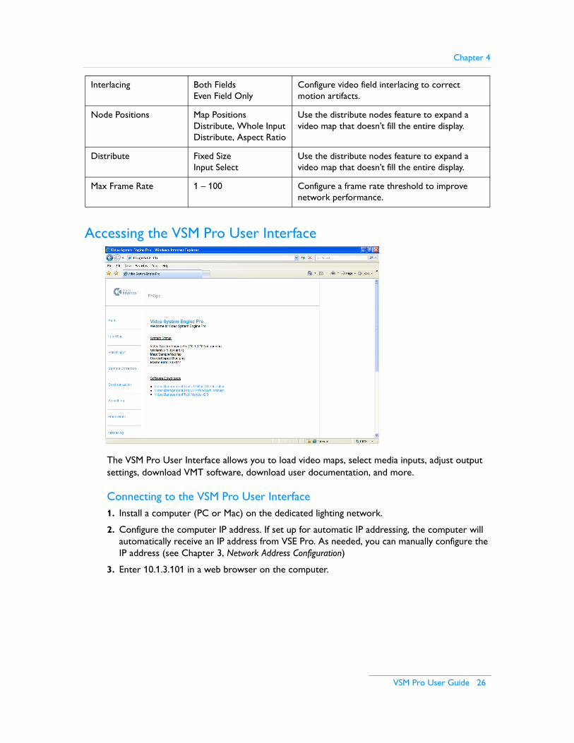
Accessing the VSM Pro User Interface
The VSM Pro User Interface allows you to load video maps, select media inputs, adjust output settings, download VMT software, download user documentation, and more.
Connecting to the VSM Pro User Interface1. Install a computer (PC or Mac) on the dedicated lighting network.
2. Configure the computer IP address. If set up for automatic IP addressing, the computer will automatically receive an IP address from VSE Pro. As needed, you can manually configure the IP address (see Chapter 3, Network Address Configuration)
3. Enter 10.1.3.101 in a web browser on the computer.
Interlacing Both FieldsEven Field Only
Configure video field interlacing to correct motion artifacts.
Node Positions Map PositionsDistribute, Whole InputDistribute, Aspect Ratio
Use the distribute nodes feature to expand a video map that doesn’t fill the entire display.
Distribute Fixed SizeInput Select
Use the distribute nodes feature to expand a video map that doesn’t fill the entire display.
Max Frame Rate 1 – 100 Configure a frame rate threshold to improve network performance.

27 VSM Pro User Guide

VSM Pro User Guide 28
Chapter 5
Working with Video Maps
OverviewSince the inception of intelligent color-changing LED lighting systems, most controllers have used the DMX512 protocol to control the nodes in an installation. The DMX control scheme is straightforward: each node receives three sequential channels of data, one channel each for the colors red, green, and blue. For example, the first node listens to channels 1, 2, and 3; the second node listens to channels 4, 5, and 6; and so on.
DMX is a viable solution for small and medium-scale LED lighting installations, or installations displaying the same abstract visual effects simultaneously on all components. However, one DMX universe comprises only 512 channels, which can control a total of 170 nodes. Output to only 170 nodes is insufficient for video display.
To display video images, LED-based displays require thousands of individually controllable nodes. VSM Pro manages large-scale lighting systems via Ethernet control. Ethernet frees a controller to use video maps instead of DMX channels.
What are Video Maps?Video maps are created using VMT mapping software, which is included with VSM Pro. Maps enable VSM Pro to accurately send data to each node in an installation, up to 250,000 total nodes. A map functions by assigning each node in the installation to a pixel of source video.
29 VSM Pro User Guide
Creating a Video MapUse the following general steps to create a map in VMT (for complete details, refer to the Video Management Tool User Guide):
1. (Optional) Upload a still image to VMT. The software displays the image on a 1024 x 768 grid.
2. Data Enabler / PDS assignment. There are two assignment methods, placeholder and interactive.
– Placeholder Data Enabler / PDS assignment enables you to create a video map off-site, prior to installation, without connecting to any lighting system components. In VMT, you perform placeholder assignment by creating a list of Data Enablers and Power / Data Supplies using pre-assigned or temporary IP addresses.
– Interactive assignment enables you to automatically discover lighting system components during installation. Once onsite, connect to the lighting network; VMT will automatically discover each Data Enabler or PDS and its IP address.
3. Place fixtures on the grid, then use the tools in VMT to orient the fixtures, change node order, etc.
4. Associate each fixture with a Data Enabler or PDS.
5. Name and save the map, then transfer to the VSE Pro controller.
CompatibilityVMT video maps are both backwards and forwards compatible: existing maps created with VMT 1.0 are compatible with VSM Pro, and newly created maps are compatible with the older VSM hardware. Maps created with the current VMT version and VMT 1.0 both use the use the .FAP file extension (Fast Map format).
Working with Video Maps
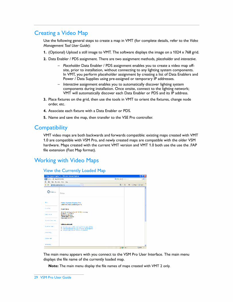
View the Currently Loaded Map
The main menu appears with you connect to the VSM Pro User Interface. The main menu displays the file name of the currently loaded map.
Note: The main menu display the file names of maps created with VMT 2 only.

Chapter 5
VSM Pro User Guide 30
Manually Load a Video Map using the VSM Pro User InterfaceOnce you have created and saved a video map file using VMT, you can load the .FAP file into to the VSE Pro controller using the following steps:
1. Start VSE Pro
2. Access the VSM Pro User Interface from a computer connected to the dedicated lighting network (enter 10.1.3.101 in a web browser)
3. From the main menu, select the Load Map
4. Browse for the .FAP file, then select the Load button
The User Interface displays a prompt once the file is successfully loaded. Return to the main menu to view the newly loaded map name.
31 VSM Pro User Guide
Automatically Load a Map to VSE Pro using VMTYou can upload a video map to VSE Pro directly from VMT:
1. Start VSE Pro
2. Launch VMT
3. Open the VSE menu and confirm that the VSE Pro is connected in the Status: field
4. Select Transfer Map to VSE
Download a Video Map from VSE Pro using VMTYou can also download a video map from VSE Pro back to VMT, for editing or backup:
1. In VMT, save your work if you have an open map
2. Open the VSE menu and confirm that the VSE Pro is connected in the Status: field
3. Select Fetch Map from VSE

VSM Pro User Guide 32
Chapter 6
Selecting an Input
OverviewVSM Pro accepts input from a video source, optimizes the content for use in an LED lighting environment, and then outputs the content to an LED lighting display.
There are three types of inputs accepted by VSM Pro: digital video, analog video, and test patterns:
Digital Inputs• DVI video
• VGA video
Analog Inputs• Composite video (PAL)
• Composite video (NTSC)
• S-Video (PAL)
• S-Video (NTSC)
Test Patterns
VSM Pro has a set of built-in test patterns that can be selected as the input. There are static image test patterns and moving image test patterns from which to choose (see Appendix A fora complete list).
33 VSM Pro User Guide
Test patterns enable you to quickly check your installation for configuration issues. For example, you can display a fixed test pattern to identify any fixtures or nodes that are not functioning. Similarly, you can display a moving image test pattern to identify any network bandwidth issues with your installation.
Note: When displaying static test patterns, VSM Pro uses a video refresh rate. This enables you to power down and power up fixtures without having to manually refresh the test patterns.
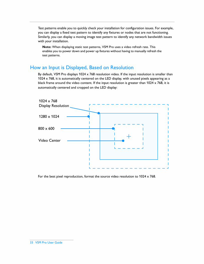
How an Input is Displayed, Based on ResolutionBy default, VSM Pro displays 1024 x 768 resolution video. If the input resolution is smaller than 1024 x 768, it is automatically centered on the LED display, with unused pixels appearing as a black frame around the video content. If the input resolution is greater than 1024 x 768, it is automatically centered and cropped on the LED display:
For the best pixel reproduction, format the source video resolution to 1024 x 768.
1280 x 1024
800 x 600
1024 x 768 Display Resolution
Video Center
Chapter 6
VSM Pro User Guide 34
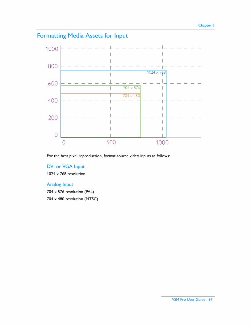
Formatting Media Assets for Input
For the best pixel reproduction, format source video inputs as follows:
DVI or VGA Input1024 x 768 resolution
Analog Input704 x 576 resolution (PAL)
704 x 480 resolution (NTSC)
35 VSM Pro User Guide
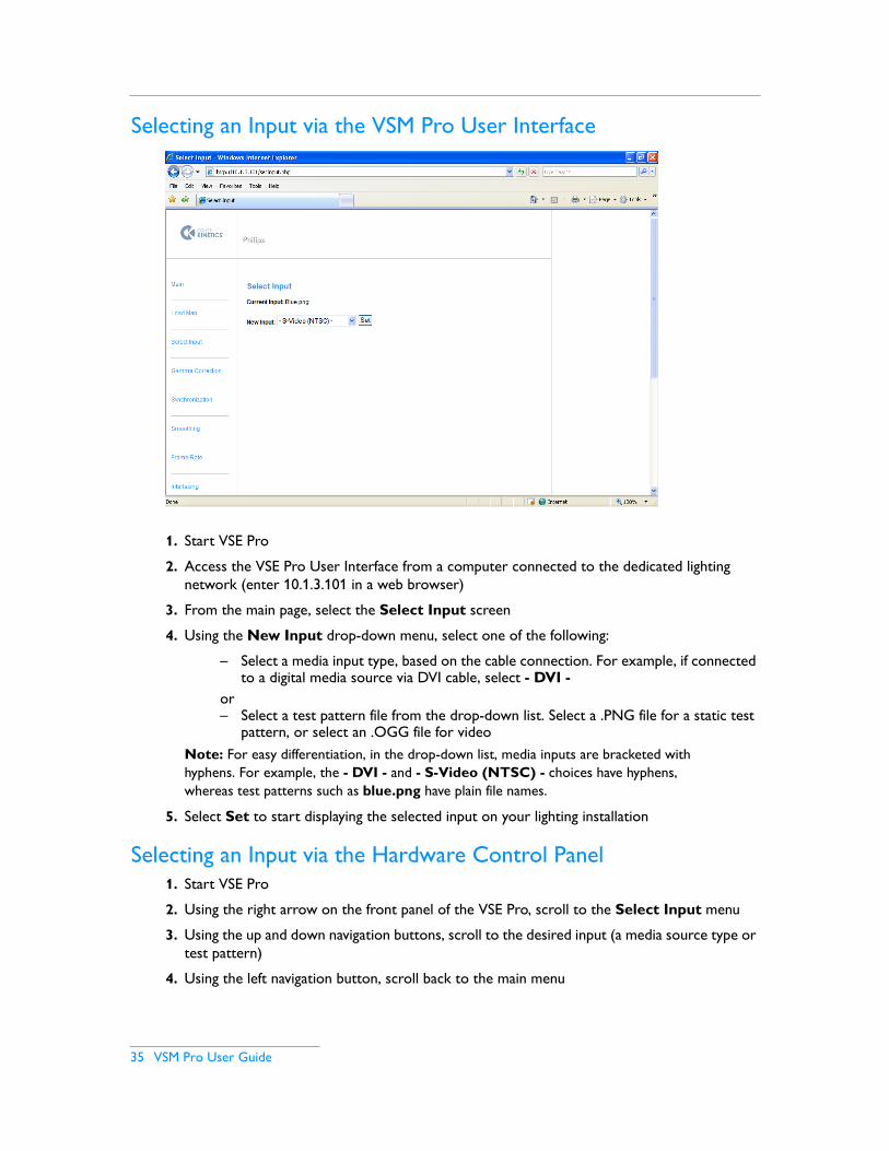
Selecting an Input via the VSM Pro User Interface
1. Start VSE Pro
2. Access the VSE Pro User Interface from a computer connected to the dedicated lighting network (enter 10.1.3.101 in a web browser)
3. From the main page, select the Select Input screen
4. Using the New Input drop-down menu, select one of the following:
– Select a media input type, based on the cable connection. For example, if connected to a digital media source via DVI cable, select - DVI -
or– Select a test pattern file from the drop-down list. Select a .PNG file for a static test
pattern, or select an .OGG file for videoNote: For easy differentiation, in the drop-down list, media inputs are bracketed with hyphens. For example, the - DVI - and - S-Video (NTSC) - choices have hyphens, whereas test patterns such as blue.png have plain file names.
5. Select Set to start displaying the selected input on your lighting installation
Selecting an Input via the Hardware Control Panel1. Start VSE Pro
2. Using the right arrow on the front panel of the VSE Pro, scroll to the Select Input menu
3. Using the up and down navigation buttons, scroll to the desired input (a media source type or test pattern)
4. Using the left navigation button, scroll back to the main menu
VSM Pro User Guide 36
Chapter 7
Optimizing Video OutputOverview
VSM Pro offers advanced features designed to enhance video output and optimize the Ethernet traffic on your lighting network:
Video Output Enhancement Features• Gamma Correction — Manage color intensity using a gamma correction file, or optimize
brightness and contrast for LED display.
• Smoothing — Use video filtering techniques to correct a ‘steppy’ or ‘noisy’ video signal.
• Interlacing — Reduce motion artifacts by selecting the field interlacing pattern best suited for your LED lighting installation.
• Distribute Nodes — A useful feature that overrides video map settings to distribute pixels on your video display.
• Display Frame — Preview the source video signal by capturing a single frame.
• Brightness — Configure the displayed brightness level.
Network Optimization Features• Packet Synchronization — Specify how VSM Pro cues and delivers packets of output data.
• Frame Rate — To troubleshoot network bandwidth limitations, set the maximum frame rate or set a packet delay.
Additional Features• Log File — Stores a log of all activity.
• Backup — Access the current video map and gamma file (if present) for backup purposes.
37 VSM Pro User Guide
Video Output Enhancement Features
Gamma Correction
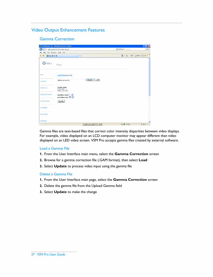
Gamma files are text-based files that correct color intensity disparities between video displays. For example, video displayed on an LCD computer monitor may appear different than video displayed on an LED video screen. VSM Pro accepts gamma files created by external software.
Load a Gamma File1. From the User Interface main menu, select the Gamma Correction screen
2. Browse for a gamma correction file (.GAM format), then select Load
3. Select Update to process video input using the gamma file
Delete a Gamma File1. From the User Interface main page, select the Gamma Correction screen
2. Delete the gamma file from the Upload Gamma field
3. Select Update to make the change
Chapter 7
VSM Pro User Guide 38
Configure a Black Level Cutoff ValueAdjusting the video black level can enhance the appearance of your LED video output. A pure black tone, as it appears in the video input, may not match what appears on your LED display. For example, dark colors, which look correct on your media server, may appear lighter on the LED display. This occurs because the LED lights are still receiving light output values that equal a small amount of light.
As needed, you can set a cutoff value, which changes all values to black after a certain threshold. For example, setting a black level value of 3 converts all light output values of 3 or less to 0, creating black output.
Use the following steps to configure a black level cutoff value:
1. From the User Interface main menu, select the Gamma Correction menu
2. Enter a new black level value (0 – 255). By default, the black level value is 0
3. Select Update to make the change
Configure a White Level Cutoff ValueSimilar to black level adjustment, but used less frequently, you can create a white level cutoff. On a scale of 0 – 255, pure white output equals 255. If white areas of video output appear too dark, you can create a cutoff. For example, if you set a cutoff value of 252, any light output value equaling 252 or greater is converted to 255, maximum output. In effect, you can control contrast using the white level setting.
Use the following steps to configure a white level cutoff value:
1. From the User Interface main menu, select the Gamma Correction menu
2. Enter a new white level value (0 – 255). By default, the white level value is 255 (maximum output)
3. Select Update to make the change
Note: Use the minimum necessary black level and white level adjustment, as RGB colors can be affected.

39 VSM Pro User Guide
Video Smoothing
Smoothing is a type of noise reduction filter designed to enhance video output. There are two levels of smoothing from which to choose: pixel smoothing and frame smoothing. Use one or both methods, as needed, until you are satisfied with the results.
• Pixel smoothing can correct ‘noisy’ video by averaging concentric rings of pixels within each frame. You can specify the number of pixel rings you want to use, up to 5.
• Frame smoothing can correct ‘steppy’ video by creating output that is an average of multiple complete frames. You can specify the number of frames that you want to average, up to 5.
Use the following steps to configure video smoothing:
1. From the User Interface main menu, select the Smoothing menu
2. Using the appropriate drop-down list, select the number of frames or pixels you want to average
3. Select Update to make the change
AVERAGE
Pixel
Pixel ring
Frame 1 Frame 2
Intra-frame
Frame 3
Inter-frame
P
P

Chapter 7
VSM Pro User Guide 40
Interlacing (Analog Inputs only)
Interlacing is a method for displaying lines of pixels on a video screen. Each frame of interlaced video contains two fields: one field contains the odd lines of video, and second field contains even lines of video. The two fields, when alternately scanned on a video screen, create a seamless image.
VSM Pro offers two interlacing options:
• Even / odd sampling processes all of the lines of pixels in the source video. Even / odd sampling is ideal for improving vertical detail, but may create motion artifacts.
• Even /even sampling removes the odd lines of video and doubles up the even lines, which reduces motion artifacts, but may produce apparent blocks of pixels.
Use the following steps to configure video field interlacing:
1. From the User Interface main menu, select the Interlacing menu
2. Using the drop-down list, select a field interlacing method
3. Select Update to make the change
Note: The effectiveness of interlacing is content-dependent. Try using different methods until you achieve an acceptable result, or select Do not interlace fields to turn off the feature.
41 VSM Pro User Guide
Node Positions
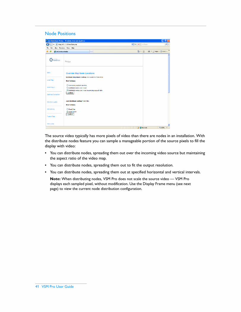
The source video typically has more pixels of video than there are nodes in an installation. With the distribute nodes feature you can sample a manageable portion of the source pixels to fill the display with video:
• You can distribute nodes, spreading them out over the incoming video source but maintaining the aspect ratio of the video map.
• You can distribute nodes, spreading them out to fit the output resolution.
• You can distribute nodes, spreading them out at specified horizontal and vertical intervals.
Note: When distributing nodes, VSM Pro does not scale the source video — VSM Pro displays each sampled pixel, without modification. Use the Display Frame menu (see next page) to view the current node distribution configuration.

Chapter 7
VSM Pro User Guide 42
Display Frame
The display frame menu enables you to capture and review a single frame of video output. The image capture feature is useful for viewing distributed pixels, checking gamma correction, and identifying whether a display issue is due to an imperfect input signal or malfunctioning fixtures.
Mark Node Positions in ImageTo fine-tune node distribution, use this setting to overlay bright green dots on top of the video image. The green dots indicate the pixels you are sampling.
Gamma Correct ImageSelect this option to preview how gamma correction and black / white levels are being applied to the video output.
Mask Node Positions in ImageCheck this setting to further fine tune node distribution. Masking node positions hides all unsampled video pixels, enabling you to preview how the sampled video output will appear on your lighting installation.
Note: To view the most recently captured video frame, use the refresh button on your web browser.
43 VSM Pro User Guide
Adjusting Brightness
The Brightness menu is only available from the hardware Control Panel. By default, the brightness level is 100%. Use the following steps to adjust brightness:
1. Start VSE Pro
2. Using the right menu navigation button, scroll to the Brightness menu
3. Using the up and down navigation buttons, scroll to the desired brightness level
4. Using the left navigation button, scroll back to the main menu
Network Optimization Features
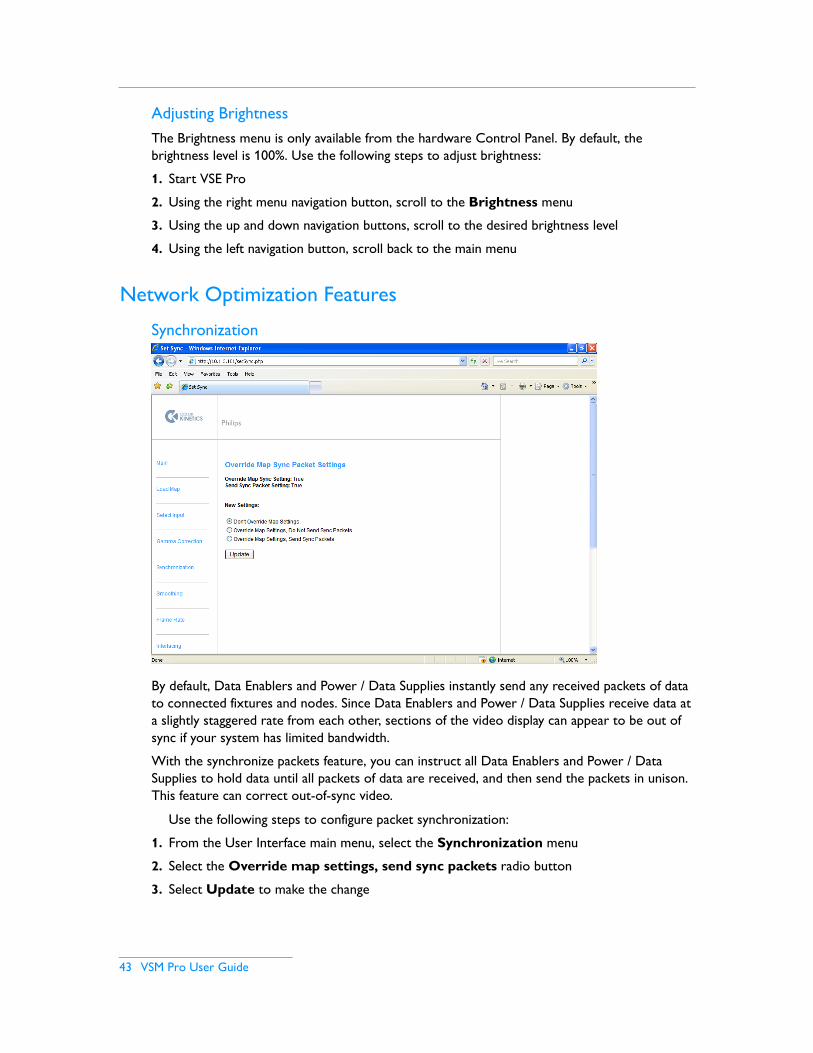
Synchronization
By default, Data Enablers and Power / Data Supplies instantly send any received packets of data to connected fixtures and nodes. Since Data Enablers and Power / Data Supplies receive data at a slightly staggered rate from each other, sections of the video display can appear to be out of sync if your system has limited bandwidth.
With the synchronize packets feature, you can instruct all Data Enablers and Power / Data Supplies to hold data until all packets of data are received, and then send the packets in unison. This feature can correct out-of-sync video.
Use the following steps to configure packet synchronization:
1. From the User Interface main menu, select the Synchronization menu
2. Select the Override map settings, send sync packets radio button
3. Select Update to make the change
Chapter 7
VSM Pro User Guide 44
Frame Rate
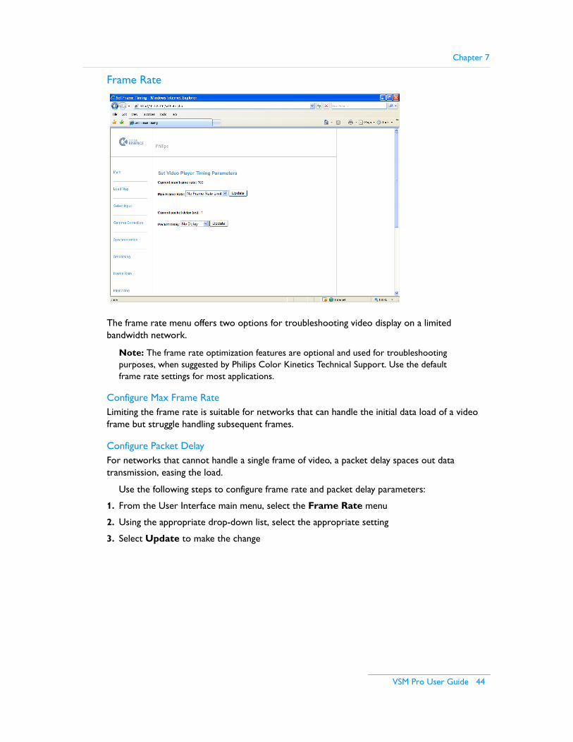
The frame rate menu offers two options for troubleshooting video display on a limited bandwidth network.
Note: The frame rate optimization features are optional and used for troubleshooting purposes, when suggested by Philips Color Kinetics Technical Support. Use the default frame rate settings for most applications.
Configure Max Frame RateLimiting the frame rate is suitable for networks that can handle the initial data load of a video frame but struggle handling subsequent frames.
Configure Packet Delay For networks that cannot handle a single frame of video, a packet delay spaces out data transmission, easing the load.
Use the following steps to configure frame rate and packet delay parameters:
1. From the User Interface main menu, select the Frame Rate menu
2. Using the appropriate drop-down list, select the appropriate setting
3. Select Update to make the change

45 VSM Pro User Guide
Additional Features
Log FileThe Log File menu provides access to VSM Pro system logs. VSM Pro maintains a current version of the log and a saved version of the previous log.
File BackupThe File backup enables you to access the currently loaded video map and gamma file (if present) for backup purposes.
VSM Pro User Guide 46
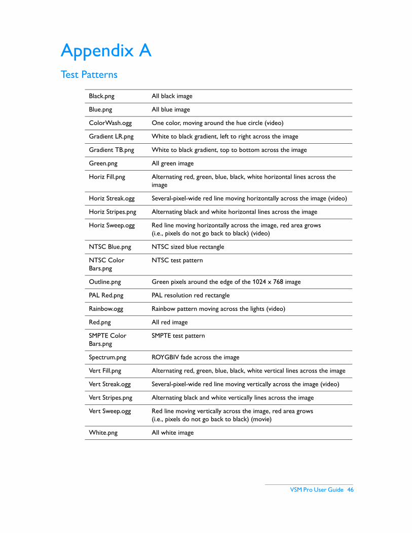
Appendix ATest Patterns
Black.png All black image
Blue.png All blue image
ColorWash.ogg One color, moving around the hue circle (video)
Gradient LR.png White to black gradient, left to right across the image
Gradient TB.png White to black gradient, top to bottom across the image
Green.png All green image
Horiz Fill.png Alternating red, green, blue, black, white horizontal lines across the image
Horiz Streak.ogg Several-pixel-wide red line moving horizontally across the image (video)
Horiz Stripes.png Alternating black and white horizontal lines across the image
Horiz Sweep.ogg Red line moving horizontally across the image, red area grows (i.e., pixels do not go back to black) (video)
NTSC Blue.png NTSC sized blue rectangle
NTSC Color Bars.png
NTSC test pattern
Outline.png Green pixels around the edge of the 1024 x 768 image
PAL Red.png PAL resolution red rectangle
Rainbow.ogg Rainbow pattern moving across the lights (video)
Red.png All red image
SMPTE Color Bars.png
SMPTE test pattern
Spectrum.png ROYGBIV fade across the image
Vert Fill.png Alternating red, green, blue, black, white vertical lines across the image
Vert Streak.ogg Several-pixel-wide red line moving vertically across the image (video)
Vert Stripes.png Alternating black and white vertically lines across the image
Vert Sweep.ogg Red line moving vertically across the image, red area grows (i.e., pixels do not go back to black) (movie)
White.png All white image

47 VSM Pro User Guide
VSM Pro User Guide 48
IndexAanalog media sources 18, 32
Bbackup files 36brightness adjustment 36, 43
CCAT-5e cable run 12, 15control panel 5, 20, 24, 35control panel menus 25correct reboot procedure 24
Ddedicated Ethernet network 5, 6, 12, 13DHCP addressing 12, 19digital media sources 32display frame 36, 42display frame, gamma correct 42display frame, mark node positions 42display frame, mask node positions 42display resolution, formatting media for 34distribute nodes 10, 36, 41DMX512 protocol 28
EEmail support contact 6
Ffiber optic cable run 12file backup 45frame rate 36, 44
Ggamma correction 36, 37gamma correction, black level 38gamma correction, white level 38Gigabit Ethernet switch 12, 15
Iinput, analog 18, 32input, digital 18, 32installation example 13, 14
installation, hardware 16installation, software 16interlacing 13, 26, 36, 40IP address configuration 20
Kkey features 4KiNET™ Ethernet 12
LLAN, lighting network 12LAN, media source 12log file 36, 45
Mmaximum viewing distance 9media server 4, 15, 32minimum viewing distance 9
Ooperating temperature 17
Ppacket synchronization 36, 43phone support 6pixel pitch 9, 10, 14planning an installation, overview 5planning an installation, data supplies 9planning an installation, fixtures 9planning an installation, layout 8planning an installation, viewing distances 9
Rrelated documentation 6resolution, digital video 10resolution, formatting source media 11resolution, NTSC video 10resolution, PAL video 10
Sselecting inputs 5smoothing, video 36, 39system configuration example 11
49 VSM Pro User Guide
Index
Ttechnical support contacts 6test patterns 13, 32, 46testing a video display 13
Uuser interface 24, 26, 35
Vvideo maps 13, 28video maps, compatibility 29video maps, creating 29video output 36VMT system requirements 19
Wworking with video sources 10, 11, 13, 16