Embed Size (px)
Citation preview

N AS A / TM-2001-210554
Videogrammetric Model DeformationMeasurement Software Package
Reference Manual for MDef.exe
Kenneth H. Cate
Langley Research Center, Hampton, Virginia
March 2001
https://ntrs.nasa.gov/search.jsp?R=20010034655 2018-06-04T03:29:28+00:00Z

The NASA STI Program Office ... in Profile
Since its founding, NASA has been dedicatedto the advancement of aeronautics and spacescience. The NASA Scientific and Technical
Information (STI) Program Office plays a keypart in helping NASA maintain this importantrole.
The NASA SIX Program Office is operated byLangley Research Center, the lead center forNASA's scientific and technical information.
The NASA STI Program Office providesaccess to the NASA STI Database, the largestcollection of aeronautical and space scienceSTI in the world. The Program Office is alsoNASA's institutional mechanism for
disseminating the results of its research anddevelopment activities. These results are
published by NASA in the NASA STI ReportSeries, which includes the following reporttypes:
TECHNICAL PUBLICATION. Reportsof completed research or a majorsignificant phase of research thatpresent the results of NASA programsand include extensive data or theoretical
analysis. Includes compilations ofsignificant scientific and technical dataand information deemed to be of
continuing reference value. NASAcounterpart of peer-reviewed formalprofessional papers, but having lessstringent limitations on manuscriptlength and extent of graphicpresentations.
TECHNICAL MEMORANDUM.
Scientific and technical findings that arepreliminar T or of specialized interest,e.g., quick release reports, workingpapers, and bibliographies that containminimal annotation. Does not contain
extensive analysis.
CONTRACTOR REPORT. Scientific and
technical findings by NASA-sponsoredcontractors and grantees.
CONFERENCE PUBLICATION.
Collected papers from scientific andtechnical conferences, symposia,seminars, or other meetings sponsoredor co-sponsored by NASA.
• SPECIAL PUBLICATION. Scientific,technical, or historical information from
NASA programs, projects, and missions,often concerned with subjects havingsubstantial public interest.
• TECHNICAL TRANSLATION. English-language translations of foreignscientific and technical material
pertinent to NASA's mission.
Specialized services that complement theSTI Program Office's diverse offeringsinclude creating custom thesauri, buildingcustomized databases, organizing andpublishing research results ... evenproviding videos.
For more information about the NASA STI
Program Office, see the following:
° Access the NASA STI Program HomePage at http://www.stLnasa.gov
• E-mail your question via the lntemet [email protected]
° Fax your question to the NASA STIHelp Desk at (301) 621-0134
• Phone the NASA STI Help Desk at(301) 621-0390
Write to:
NASA STI Help DeskNASA Center for AeroSpace Information7121 Standard DriveHanover, MD 21076-1320

NASA/TM-2001-210554
/
Videogrammetric Model Deformation
Measurement Soft:ware Package
Reference Manual for MDefexe
Kenneth H. Cate
Langley Research Center, Hampton, Virginia
National Aeronautics and
Space Administration
Langley Research CenterHampton, Virginia 2368t-2199
March 2001

The use of trademarks or names of manufacturers in the report is for accurate reporting and does not constitute an I
] official endorsement, either expressed or implied, of such products or manufacturers by the National Aeronautics ]
[and Space Administration. I
Available from:
NASA Center for AeroSpace Information (CASI)
7121 Standard Drive
Hanover, MD 21076-1320
(301) 62 i -0390
National Technical Information Service (NTIS)
5285 Port Royal Road
Springfield, VA 22161-217 !
(703) 605-6000

Contents
Overview ............................................................................................................... 3
Descri ti_Loa............................................................................................................................... 3
Minimum System Requirements .................................................................................................. 3
Optional Parts ........................................................................................................................... 3
Hardware Connections ............................. ,, .......................................................... 3Trigger Connection ...................................................................... 4
Data Acquisition S_.s_LemCDAS) Interface ..................................................................................... 4
RS-232 Connection .................................................................................................................... 4
Network Connection .................................................................................................................. 4
Software Setup ......................................... .,, .......................................................... 4Necessary Files ......................................................................................................................... 5
Miscellaneous Files .................................................................................................................... 5
Param.dat ................................................................................................................................. 5
FlapAngle,ini ............................................................................................................................ 5
GetFile.bat ................................................................................................................................ 5
For-A.exe ................................................................................................................................. 6
For-A,ini .................................................................................................................................. 6
WorkDirectory Structure ............................................................................................................ 6
Output Fil¢,s .............................................................................................................................. 6
Initial Setup .............................................................................................................................. 6
MDef Operation .............................................................................................. 10Figure I - Sample Start-up_ Screen Showing the FJ_a_p=Ang/e D_ ................................. 10
Figure 3 -Sample FJap=A_e Displa_ .............................................................................. 12Serial Connection ....................................................................................... 12
N¢lwork Connection ................................................................................................................ 12
Socket Connection ................................................................................................................... 13
Figure 4 - Sample" S_, Calibrati on Plate ........................................................................ 13
Figure 5 - Sample 'Step' _Colibration Plate with !!!uminatio_n ............................................ 14
Figure 6 - Sample lma_ge with Targets Located by 'B' Test Using a S.ingle Re_gi_ ........... 14
Figure 7 - Sample !m_e with Targets Located by 'B' Test Using Mu_ipl¢ Re_gions 15
Setup Procedure ................................................................................................. 15Camera Setup aod Orientation ..................................................................................... 15
Configuration ............................................................................................... _.......................... 15Distortion ............................................................................................................................... 16
Appendix ............................................................................................................. 17Sample Param.dat File .............................................................................................................. 17
Sample FhapAngl.ini File ....................................... , .................................................................. 19
Sample Video,dat File (Numbers only. text in ital_c_sadded for identification only) .......................... 20
Sample MDef.send File (Text in italics added for identification only) ............................................. 20
Sample Tunnel.log File ............................................................................................................. 21
Sample Centxxxx File .............................................................................................................. 23
Sample Cerrxxxx File ............................................................................................................... 24
Sample XYZxxxxx File ............................................................................................................ 25

Sample XYZMean.dat File ........................................................................................................ 25
S_tmple ZSlp File ..................................................................................................................... 25
Sample ZlntSlpe File ................................................................................................................ 26
2

Overview
Description
The Video Model Deformation (VMD) software package (MDef.exe or MDef) was written as an
MS-DOS application for use with an Epix Model-12 video capture card. MDef.exe can capture images in
the Epix card's memory, locate light or dark targets (a.k.a. blobs) within the images, and compute the
XYZ displacements for each target. When enabled, MDef can also compute the amount of twist along
specified rows of targets.
Minimum System Requirements
IBM PC style computer (80286 processor or better)Motherboard with two, adjacent, full-length card slots with no obstructionsEpix Model 12 video capture cardEpix type video breakout connector (1DB25)Video camera (pixel-clock output recommended) with power supplyBlack and white (B&W) or color monitor for viewing video output from the Epix cardTwo RG-59 cables (one for video signal from camera to Epix card, the other for video signal to monitor)Retro-reflective material or paint for targets
Optional Parts
IBM PC style computer (80286 processor or better)Mounting hardware for cameraRG-59 cable for pixel-clock signal from camera to Epix card (if this signal is available)B&W or color monitor for viewing video input to Epix cardRG-59 cable for 2ndmonitor
Light source (variable intensity recommended) such as fiber optic bundleVariable power supply for controlling light source remotelyCable for connecting power supply to light source
Ethernet card and cable for network connection
Other parts may be needed depending on if wind-tunnel data is being sent to the VMD system, and
the method of transfer (such as by RS-232 or a network connection).
Hardware Connections
All video and pixel-clock signals are routed through RG-59 (75 ohm) co-axial cable. Connect the
Video output from the camera to the video input of a B&W monitor then connect the output from the
monitor to the video input lead of the Epix card (labeled VIN). If the camera has a pixel-clock output (a
continuous signal of approximately 14.318MHz), it is connected to the external clock input lead of the
Epix card (labeled CLOCK_IN). The video output lead of the Epix card (labeled GREEN) is connected
to the video input of the second B&W monitor.
3

Trigger Connection
The Epix card has a trigger input lead (labeled EXT_IN) that can be used to trigger data taking. The
trigger is a TTL level signal with a high to low transition. Since EXT_IN floats high (~5V), a simple
short to ground (0V) is all that is needed as a trigger signal.
An alternate method of triggering data taking is via a network connection to the Data Acquisition
System (DAS) at the facility where the test is being held. A network connection requires the computer to
have an Ethernet card installed, and network addresses to be assigned to the computer and the network
port that is to be monitored. When MDef is started with the proper command-line options, it will establish
a network connection with the DAS; MDef will then pole the DAS several times a second to determinewhen to take data.
Data Acquisition System (DAS) Interface
The serial port on the computer can be used to receive wind tunnel data through a standard RS-232
cable. An external program is written to open the port, read the data stream, close the port, write the data
to a copy of Video.dat (See Appendix), and then return to the calling program. The batch file GetFile.bat
is used to call the external program.
RS-232 Connection
The serial port on the computer can be used to receive wind tunnel data through a standard RS-232
cable. An external program is written to open the port, read the data stream, close the port, write the data
to a copy of Video.dat (See Appendix), and then return to the calling program. The batch file GetFile.bat
is used to call the external program.
Network Connection
An Ethernet connection can be used to receive wind tunnel data as well as triggering data taking.
After the computer has been assigned an IP address on the network, MDef.exe can be called with the
appropriate IP address and Port number for the Data Acquisition System server.
Software Setup
The VMD code (MDef.exe) is normally stored (along with other useful programs) in a directory
named Facility\Code off the root directory of one of the hard drives (Ex.: C:\Faeility\Code). This
directory is usually added to the search path in Autoexec.bat. A FacilityWlates directory is also used as
a place for storing the calibration plate data files. Directories are created in the Facility directory" named
after the facility where a test is being held (such as TDT for the Transonic Dynamics Tunnel). Work (or
test) directories are created in the appropriate facility directory.
If the test number was 542 and a conventional wing was being tested at the Transonic Dynamics
Tunnel (TDT), the work directory might be:
C AFacility\TDTkT542.CON
4

Since MDef.exe was written as a DOS application, all file names and directory names need to be kept
short (8 characters for a name, a period, and 3 characters for an extension). MDef.exe creates special
directories for it's output files within the work directory, as they are needed for the output files.
Necessary Files
MDef.exeParam.dat
FiapAngl.ini
The main VMD program
The test configuration file; See Appendix for sample
Flap and wing angle configuration file
Miscellaneous Files
Note: * denotes
• * denotes
• GetFile.bat
• For-A.exe
• For-A.ini• * MDef.send
ReRun.exe
ReDoFlap.exe
a file or program that may not be needed for the normal operation of MDef
a file that may be needed by the DAS
DOS batch file used to obtain the wind tunnel data when a socket connection is
not used
Reads a stream of RS-232 data and uses it to create a copy of Video.dat
Configuration file used by For-A.exe
Sample script file used by the DAS to format and send data to MDef via a socketconnection
Re-processes the target data using a modified copy of Param.datRe-processes the Flap-Angle data (FlapAngl.txt) using a modified copy of
FiapAngl.ini
Param.dat
The configuration file Param.dat is a simple text file containing information about the placement and
orientation of the video camera, the image size to be used, the maximum and minimum target sizes, the
number of targets to search for, and other information needed by MDef. Most of the lines in Param.datcan contain comments (which are ignored by MDef).
FlapAngle.ini
The flap and wing angle configuration file FlapAngl.ini is a simple Windows@ type INI file
specifying which targets are grouped into 'rows' for computing wing twist or angle-of-attack (AOA).
FlapAngl.ini also identifies the row to be used as a reference and the correction values used in the
computations.
GetFile.bat
MDef calls GetFile.bat when it needs to retrieve the wind tunnel data. GetFile.bat is either set up to
copy a file off a shared drive to Video.dat (in the current work directory) or it calls another program (suchas FOR-A.exe) to read the tunnel data from an RS-232 stream and write the data to a copy of Video.dat.
5

For-A,exe
When the Wind tunnel data is being sent to MDef over an RS-232 cable, FOR-A.exe (or a similar
program) can be called by GetFile.bat. For-A reads a stream of RS-232 data and uses it to create a copy
of Video.dat in the current directory.
For-A.ini
The configuration file For-A.ini is used by For-A to identify what characters (or words) in the RS-
232 stream to use to identify the wind tunnel data. For-A can be used as a stand-alone program to
continuously read and display the wind tunnel data. Labels can be added to For-A.ini to be used when
displaying the data.
Work Directory Structure
When the VMD code (MDef.exe) is run, sub-directories are created in the work directory for the
output files but only when data is to be written. The directories that MDef creates and uses are:
Centroid_XYZ_
ZSLP\
Images\
Centroid data files are saved here (Centxxxx or Cerrxxxx)
XYZ data files are saved here (XYZxxxxx)
Z-Intercept/Slope files are saved here (ZSLPxxxx)RAW and TIFF image files are saved here
The use of 'xxxx' in a file name designates a number that is padded with leading zeros so that the file
name is eight characters long and the numeric part appears right justified such as Cent0025. If MDef is
triggered to take data but the point number has not advanced, padded numeric extensions are added to the
file names to prevent overwriting previous data. Example: If MDef were triggered to take data for pointnumber 25 a second time, the new centroid file would be named Cent0025.001. The XYZ and ZSLP files
are named similarly. The reason for padding the file names with zeros is to make sorting easer.
Output Files
MDef creates several output files. When wind-tunnel data is read, a copy of the data is written to
Tunnel.log. When data is taken, the centroid locations within the image plane (in pixels) are written to
the temporary file Blobs.dat. If any row of targets does not contain the proper number of targets,
Blobs.dat is copied to a Cerr type file (ex: Cerr0025) in the Centroid directory. Any 'good' rows are
written to a Cent type file (ex: Cent0025) in the Centroid director)'.
Computations are made to using the 'good' centroid locations to determine the X, Y, and Z locations
of the targets in 3-dimensional space; the results are written to a XYZ type file in the XYZ directory.
Averaged X, Y, and Z values for all fields are written to XyzMean.dat in the work directory. The slope
(or angle-of-attack) of each row is calculated, along with the Z-axis displacement and standard-of-
deviation values, and written to Zintslpe. Sample output files can be found in the appendix.
Initial Setup
Before MDef can be used for a new test, the configuration file Param.dat must be created. The
following is a line-by-line description of the file.
6

Line
1
89
1011
12
13
14
15
16
17
1819
20
21
22
23
24
25
Value (Ex.)I
752
0
2400
0.026
0.011
363.2100.5
362101
0.0
1.0
00
2
12.757.9047
180.1271
89.0504
-5.4308
28.5556
-27.3561
1
Parameter
Tab point
Horizontal pixels
Horizontal offset
Vertical pixelsVertical offset
Vertical pixel spacing ofcamera in mm
Horizontal pixel spacing ofcamera in mm
Pixel x principal point
Pixel y principal pointPixel x symmetr3: point
Pixel y symmetry' pointk l radial distortion mm^-2
Unitless sh_ratiolocked/unlocked
Pixel x shift unlocked to locked
Pixel y shift unlocked to lockedDe ltax
Delta_y
Camera constant c in mm
Deg omega
Deg phi
Deg kappaInch Xc
Inch Yc
Inch Zc
White-on-black
Description
Used as a starting value for the point numbers when eitherVideo.dat or a socket connection is not available. A negative
point number indicates that flap-angle computations are to bedone; otherwise, MDef defaults to a Zintslpe display. If the
ASCII character 124 (T) is placed on this line, the text
following the character is used as a title for the test.
The image dimensions used by the Epix card (normally 752X 240 for non-interlaced images). If a full image is notdesired, the horizontal and vertical offsets (in pixels) of the
portion of the image to capture is given on lines 3 and 5,
respectively.Normally 0, use - 1 to center the captured region.
Maximum = 2401,480 if interlace is ON.
Normally 0, use - I to center the captured region on thescreen.
The spa.cing of the camera's pixels in millimeters. For aHitachi model KP-MIU CCD camera, the numbers are
approximately 0.026 vertical, and 0.011 horizontal.
To be measured during configuration.
To be measured during configuration.
Measured by zoom symmetry on image.Measured by zoom symmetry on image.The K I radial distortion factor in mm^2. If any of the
variables K2, K3, PI or P2 are needed, they can be insertedbetween this line and the next. The extra variables are added
in order. Any unneeded variables in the set MUST be insertedand set to zero. If only K2 and PI are needed, values for K2and K3must be included.
How much to increase the target bounding box over thedefault minimum of 4.
How much to increase the target bounding box over thedefault minimum of 2.
When targets (or blobs) are found, a rectangular areasurrounding the target is determined. The background level is
measured along the top and bottom edges and is subtractedfrom the entire rectangle. The box size can be adjusted with
the values Delta_x and Delta__y.
Camera's rotation (orientation) about the X-axis within thewind tunnel.Camera's rotation about the Y-axis within the wind tunnel.
Camera's rotation about the Z-axis within the wind tunnel.
Camera's position in relation to the model in inches (along airflow axis).
Camera's horizontal position in relation to the model ininches.
Camera's height in relation to the model in inches.0 = Dark targets on light background, else Light targets on a
7

26 12 Minimum_blob_mass27 4 Fieldsdelay
28 60
29 I0Target threshold
Maximum buffers to process
30 0 Skip buffer offset
31 0 Row orientation
32 2 Number of rows of targets
33 Row 1Information
34 I I Number of targets on Row 135 1.0 Y/b/2 (Row 1)36 0.0 z ref offset (Row I)
37 0.0 AOA ref offset (Row 1)
38 1.0 Z ref slope (Row I)39 1.0 AOA refslope (Row I)
40 3 Ref point (Row 1)
41 Row 2Information
42 11 Number of targets on Row 243 2.0 Y/b/2 (Row 2)
44 0.0 z ref offset (Row 2)45 0.0 AOA ref offset (Row 2)
50 1.0 Z ref slope (Row 2)
55 1.0 AOA refslope (Row 2)60 3 Ref point (Row 2)
dark background.Minimum number of pixels in a valid target.
If <= 0, get tunnel data AFTER scanning for blobs. Somevideo capture cards require a few fields to be skipped after a
hardware trigger before images are captured. The fields delay
determines the number of fields to skip. The sign on thisnumber is used to control when the wind tunnel data is read.
Gray-scale level for detecting targets; see White-on-black.
When set to 0, MDef computes this value based on the imagesize and size of the Epix card's memory.
When set to 0, MDef processes ever)' buffer. A value of 5would cause MDef to process the fields in the sequence: I, 7,
13, etc.If less than 0, MDef does not sort the targets into rows. If set
to 0, MDef sorts the targets into vertical rows, else horizontal.
The targets are aligned as rows running parallel to themodel's center axis. This number sets the number of rows for
sorting, etc.Start of information describing the target rows. This line is
plain text.
The normalized semi span offset.
See equation belowSee equation below
See equation belowSee equation below
Point within a row to use to determine z_int; can be a fraction
to specify a position between two targets.
The normalized semi span offset.
See equation below
See equation belowSee equation belowSee equation below
Point within a row to use to determine z_int; can be a fraction
to specify a position between two targets.
When targets (blobs) are found, a rectangular area surrounding the target is determined. The
background level is measured along the top and bottom edges and is subtracted from the entire rectangle.
The box size can be adjusted with the values Delta_x and Delta__y.
Some video capture cards require a few fields to be skipped after a hardware trigger before images are
captured. The fields delay (line 27) determines the number of fields to skip. The sign on this number is
used to control when the wind tunnel data is read: before or after the captured images are processed.
After targets are found within an image, they are sorted to determine their order. When multiple
regions are used, sorting may not be required.
The information in the 'ROW x INFORMATION' tables is used to compute the angle of the 'row'
and the z-displacement of a specific target. The equations are:

z_int = (intercept - zref) * zref slope
angle = (aoa - aoaref) * aoaref_slope
After all of the Row tables is found a table of miscellaneous information starting with a header line.
Thres nw.x nw.y minx miny maxx maxy yref[] compl bac sub add sub XI00 35 30 4 2 21 ii O. 00000 0 1 3 O. 00000
Z Mtar se.x se.y
0.00000 3 182 240
Columns 8, 12, and 13 are used to specify the locations of each target in the order that they are placed
in after located and then sorted. The rest of the columns are used to specify information for the search
region(s). If the entire image is to be used as the first and only region, the first threshold value in this table
is set to a negative value. The default threshold value on line 28 will be used instead but columns 4
through 14 will be used as usual.
The columns are:
Column1
LabelThres
Description
The threshold value for a search region (region of interest) within an image. A positive
value here overrides the default threshold (line 28 above). A negative value marks theend of the search region information within this table. The number of consecutive
positive threshold values determines thc number of regions.
2,3 nw.x, nw.y The area of interest boundaries, in pixel numbers for a search region within an image.
nw.x and nw.y designate the "north-west" or upper-left boundary.sw.x and sw.y designate the "south-west" or upper-left boundary.
4,5,6,7 minx, miny,
maxx, maxy
The maximum and minimum sizes for the targets within each search region. If the entire
image is used as a single region, lhc first set of these values is used as the default
y-tel The target's Y-reference value. Each target's y-ref is indicated. This value is thedistance of each target from the centerline of the model, in inches.
compl This value determines if the pixels within the rectangle bounding a target are to becomplemented.
10 bac_sub This value determines if the background is to be subtracted from every pixel in thetarget rectangle.
I1 add_sub An additional value to subtract from the pixels in the target rectangle.
12 X The targets' X-reference value in inches.
13 Z The targets' Z-reference value in inches.
14 Mtar The maximum number of targets to be found in this search region. When this number is
reached, MDef begins searching for targets in the next region.
15, 16 se.x, se.y The location (in pixel numbers) defining the boundary of the "south-east" corner of asearch region.
9

MDef Operation
When started, MDef reads Param.dat. If the number on the first of Param.dat is negative, MDef reads
FlapAngl.ini. MDef then sets the Epix card to the configuration specified in Param.dat. If the network
address and port number are given, MDef attempts to establish a connection to the Data Acquisition
System. MDef next reads the current wind-tunnel information, and sets up the normal operation display
(See Figure 1).
Figure 1 - Sample Start-up Screen Showing the Flap-Angle Display
MDef can be started with various command-line options. A list of command-line options can be
obtained by starting MDef with a command-line option of '?' or '-?' (Ex.: MDef.exe ?). The command-
line options are:
-F
-A
-P
-E
-U-1
?
- Load a still image File for processing instead of capturing and processing new images
- IP Address for network access to the Data Acquisition System (DAS)- Port number for network access to the Data Acquisition System (DAS)
- Disable External Triggers (can be enabled and disabled from within MDef)- Disable PixeI-Clock Lock (Unlock; can be enabled and disabled from within MDef)
- One-Shot operation, Take one ( ! ) data point and quit
- Display a list of command-line options
The -F, -A, and -P options are followed by colons and the appropriate information, such as:
MDef -F:Sample.raw -F:Sample2.raw -A:255:255:255:255 -P:50001
It should be noted that MDef only loads 8-bit grayscale image files that are uncompressed and have
no header such as the images that MDef creates with the Save-Image command (ALT-S). Consecutive
image files are loaded into consecutive imagebuffers starting with buffer one.
10

Someof theusercontrollable options are displayed on the second line of the screen with 'hot keys'
highlighted. Function key F1 can be used to pull up a scrollable help screen. Normal data taking can be
manually triggered be pressing the letter T. A sample image can be captured and processed without
writing to any of the append files by pressing the letter B; this is what is referred to as a 'B' test as
'Boxes' are drawn around any regions of interest after the targets are located. The 'B' test also numbers
the targets and the regions (See Figure 7). The 'B' test is frequently used to confirm that the targets are
within the proper image search region(s), the maximum and minimum blob sizes are set correctly, and the
thresholds are set correctly for each search region.
B:
C:E:
F:
I:
K:
L:P:
Q:R:
T:
W:Z:
ALT-F:
ALT-L:
ALT-S:
ALT-U:
Do a l-Shot Blob Test, number the targets found, draw boxes around each search region
Toggle PixeI-Clock Lock
Toggle External trigger enable
Toggle between Flap-Angle data display and AOA data display
Toggle Independent blob trackingToggle BIob tracking (not normally used in this version of MDef)
Toggle Live video mode
Toggle Auto increment of Point number
Quit this program
Toggle Real-time image captureTake data (Manual trigger)
Walk (Step) through the image buffers
Zero the Wing and Hap-Angle dataToggle Hap-Angle computations enable
Change LUX (threshold) setting for an), region
Save current image buffer as a raw image file and as a TIFF file
Update the parameter file
The up and down arrow keys can also be used to change the image buffer being viewed.
Figure 2 - Sample Zintslpe Display
II

WhenMDef runs,twotypesof resultdisplaysareavailablefor viewing.Onedisplayis thenewerFlap-Angledisplay(asshownin Figures! and3),andtheotherdisplayis theolderZ-Intercept/ Slope
(Zintsipe) display (as shown in Figure 2).
Figure 3 - Sample Flap-Angle Display
The green bar on the screen, and the text on the line immediately below it, displays some of the
information from the wind tunnel's Data Acquisition System (DAS). The wind tunnel data can be
obtained by accessing a file on a shared drive, reading serial data from an RS-232 stream from the DAS,
or by a network connection to the DAS. MDef can also read the tunnel directly from the DAS by a'socket' connection over the network.
Serial Connection
If a serial connection is used, the DAS must be set up to send data continuously over an RS-232 cable
to the computer that is running MDef. A copy of GetFile.bat is written that calls a program, such as For-A.exe, which can read the RS-232 stream and write the data that it receives to a copy of Video.dat in the
work directory of the MDef computer. A configuration file (For-A.ini) must be set up for the program to
know how to interpret the RS-232 stream in order to write Video.dat.
Network Connection
The computer on which MDef is being used must be set up with an Ethernet connection and properly
configured (local IP address, etc.). If the wind tunnel data is being written to a shared drive, the data mustbe in the same format as Video.dat. A copy of GetFile.bat is written that copies the data file from the
shared drive to Video.dat in the work directory of the MDef computer.
12

Socket Connection " "
The MDef computer is set up the same way as for a simple network connection. MDef must be run
with the command-line options for the DAS IP address and a valid port number to talk directly to the
DAS. The DAS must also be set up to send the required data in a specific order (See MDef.send in the
Appendix).
Figure 4 - Sample "Step' Calibration Plate
13
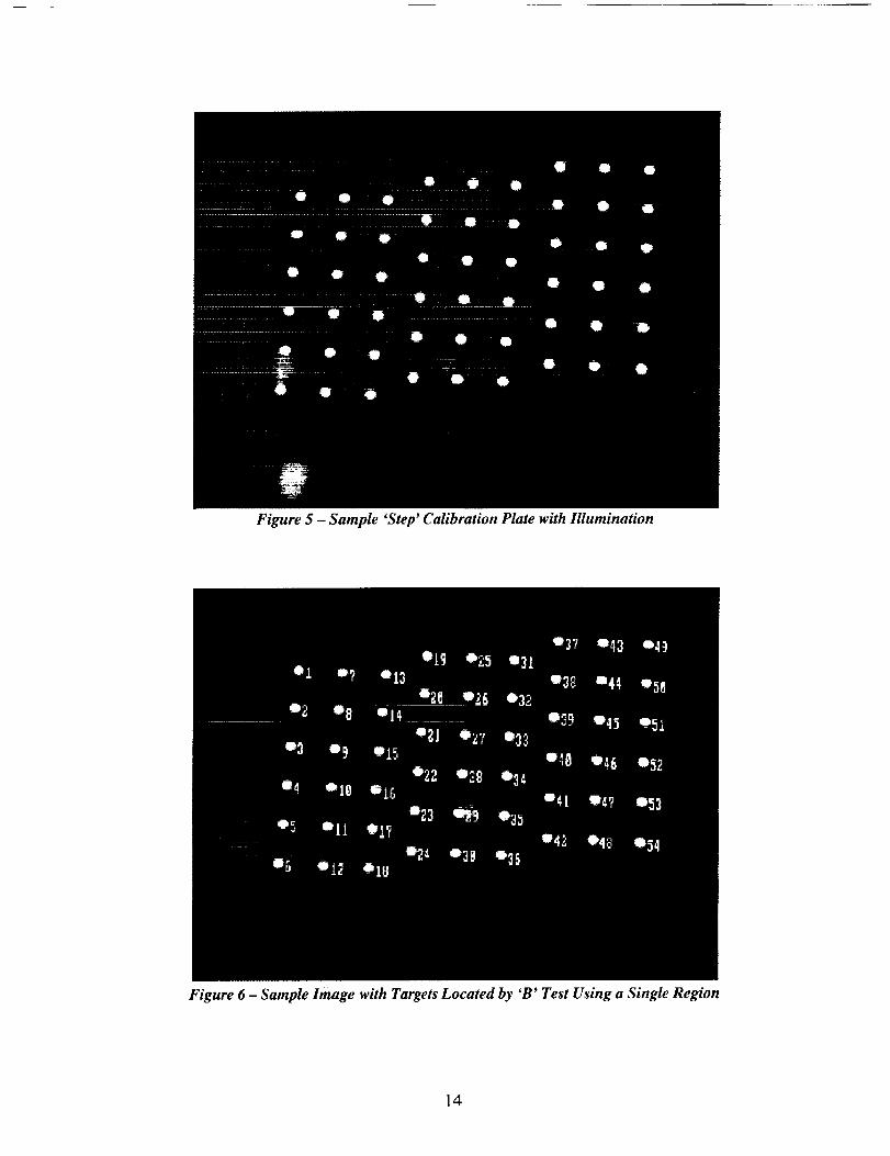
Figure 5 - Sample 'Step' Calibration Plate with Illumination
Figure 6- Sample Image with Targets Located by 'B' Test Using a Single Region
14

Figure 7 - Sample Image with Targets Located by 'B' Test Using Multiple Regions
Setup Procedure
Camera Setup and Orientation
The video camera is mounted on a fixed bracket or pan-tilt mechanism behind the wall of a wind
tunnel's test section so that it views the model through a window. The camera is rotated 90 degrees so that
the flow direction is vertical on the image plane as seen on the monitors. A variable intensity light source
is usually placed near the camera to illuminate the retro-reflective (or white) targets and is adjusted, along
with the aperture setting on the camera, to produce a high-contrast image of the targets on the monitors. In
addition to the usual bright targets on a dark background, MDef can be set up for dark targets on a light
background. Set White-on-black (line 25 in Param.dat) for the default, or set the flags in the compl
column (lines 42+) for each region.
Configuration
Initial values for the camera's location are obtained by measuring the camera's location with respectto the model. The Y value (line 22 of Param.dat) is the distance (in inches) from the camera to the model
along a horizontal line perpendicular to the centerline of the wind tunnel. The sign of Y is positive if thecamera is on the right side of the model (air flow is to the left when viewed by someone standing next to
the camera facing the model). The Z value (line 23 of Param.dat) is the vertical displacement of thecamera from the centerline of the model. A positive value of Z implies that the camera is above the
centerline of the model. The X value (line 21 of Param.dat) is the distance the camera is behind target
number one on the model and is frequently less than ten inches.
15

Sincethecamera is usually rotated 90 degrees along it's line of sight, the initial value for kappa is
(line 21 of Param.dat) set for 90. Omega (line 19) is the camera's rotation around the axes parallel to the
wind tunnel's airflow (or the centerline of the model). Phi is the camera's rotation around a vertical axis.
A target plate (whose target locations have been measured]is placed near the model, within the field
of view of the camera (see figure 4), and oriented parallel to the main axes of the wind tunnel. The targetplate is usually mounted on a tripod such that the target plate can be translated (moved) at least one inch
in along of the three axes. A copy of the target plate's reference file is created with the targets arranged in
the order that they will be detected by MDef. The targetnearest the top left corner of the images on themonitors is referred to as target 1, with the target below it referred to as target 2. If horizontal sorting is
selected in Param.dat, the target to the right of target 1 is target 2. The X, Y and Z columns in the
reference file are arranged to reflect any changes in the target plate's orientation. One or more columns
may need their signs reversed. The values from the new target reference file are copied to the columns in
Param.dat labeled yref[], X, and Z.
After the initial values are placed in Param.dat, a 'B' (Box) test is performed. Confirm that the targets
are being identified properly and that the target plate's orientation angle is near zero. If some of the
targets are not found, any of the following may need to be changed:
1) The lighting (the targets may not be bright enough)2) The aperture of the lens (there should be sufficient contrast between targets and background)3) The threshold level(s) in Param.dat (line 28 or column I in the region table)
4) The maximum and/or minimum target size(s) in Param.dat (columns 4-7 in the region table)5) The camera's orientation (all of the targets must be in the field of view for the entire range of
angles the model is to be set during the test)
6) The focal length of the lens (See item #5)
Distortion
Additional software is available that can process data files created by MDef (when using a pre-
measured target plate) that will calculate the pixel principal point (lines 8 and 9), the pixel symmetry
point (lines 10 and I1), as well as the distortion correction value kl (line 12) for use in Param.dat.
Although kl is placed on line 12 of Param.dat, if the other correction values are needed, they can beadded immediately after kl in the order: k2, k3, pl, and p2.
-i.i13e-003 kl radial distortion mm^-2 ( Put K2,
0.0 k2 radia] distorti.or_ mm_-4
1.0000000 Unitless sh ratio locked/unlocked
K3, P1 & P2 after this ...
16

Appendix
All output files (with the exception of the image files) are plain text files with header and commentlines prefixed with a percent sign. This allows the files to be loaded into Matlab ® for generating special
plots.
Sample Param.dat File
-48
752
0
240
0
0.02599700
0.01099700
370.00
108.00
374.30
107.60
-i.i13e-003
1.0000000
0.00
0.00
1
1
12.8950
Tab Point ITDT Test 542 Smart Wing
Horizontal pixels ( Must be divisible by four, Max=752 )
Horizontal offset ( -i to center )
Vertical pixels ( Max = 240, 480 if interlace On )
Vertical offset ( -I to center )
Vertical pixel spacing of camera in mm
Horizontal pixel spacing of camera in mm
Pixel x principal point ( To be measured during cal )
Pixel y principal point ....
Pixel x symmetry point ( Measured by zoom symmetry on image )
Pixel y symmetry point ....
kl radial distortion mm^-2 ( Put K2, K3, P1 & P2 after
this line if needed )
Unitless sh ratio locked/unlocked
Pixel x shift unlocked to locked
Pixel y shift unlocked to locked
Delta x ( how much to increase the box over min of 4 )
Delta_y ( how much to increase the box over min of 2 )Camera constant c in mm
-151.4449156222003 Deg omega
-3.079673156343532 Deg phi
-83.94443400192141 Deg kappa
-1.627920426876803 Inch Xc
80.248 42.51402182382443 Inch Yc
-86.09295102229963 Inch Zc
1 White-on-black
12 Minimum blob mass
4
( 0 = Dark targets, else Light )
Fields delay ( if <= 0 get tunnel data AFTER scanning for
blobs )
i00 Target threshold ( difference for White-on-black )
60 Maximum buffers to process ( 0 to let it compute number )
5 Skip buffer offset ( 0 to process every buffer )
0 Row orientation ( <0 = No sort, 0 = vertical, else horizontal
)5 Number of rows of targets ( See: ;kmes54b.tdt in plates
directory )
ROW 1 INFORMATION
Number of targets on Row 13
0.0000
0.0000
0.0000
Y/b/2 (Row 1
Z ref offset (Row 1
zref_slope
AOA ref offset (Row 1
aoaref_slope
Z ref slope (Row i)
AOA ref slope (Row I)
1.0000
1.0000
z int = (intercept - zref) *
angle = (aoa- aoaref) *
17

2.0000 Ref Point
ROW 2 INFORMATION
3
0.406 Y/b/2
0.0000 Z ref offset
0.0000 AOA ref offset
1.0000 Z ref slope
1.0000 AOA ref slope
2.0000 Ref Point
(Row I) (x.y -> .y after point x)
Number of targets on Row 2
(Row 2)
(Row 2)
(Row 2)
(Row 2)
(Row 2)
(Row 2) (x.y -> .y after point x]
ROW 3 INFORMATION
3 Number of targets on Row 3
0.535 Y/b/2
0.0000 Z ref offset
0.0000 AOA ref offset
1.0000 Z ref slope
1.0000 AOA ref slope
2.0000 Ref Point
ROW 4 INFORMATION
3 Number of targets on Row 4
0.724 Y/b/2 (Row 4
0.0000 Z ref offset (Row 4
0.0000 AOA ref offset (Row 4
1.0000 Z ref slope (Row 4
1.0000 AOA ref slope (Row 4
2.0000 Ref Point (Row 4
ROW 5 INFORMATION
2 Number of targets on Row 5
0.850 Y/b/2 (Row 5
0.0000 Z ref offset (Row 5
0.0000 AOA ref offset (Row 5
1.0000 Z ref slope (Row 5
1.0000 AOA ref slope (Row 5
1.5000 Ref Point (Row 5
Thres nw.x nw.y minx miny maxx maxy
Z Mtar se.x se.y
i00 35 30 4 2 21
0.00000 3 182
I00 185 i0 7 3 21
0.00000 ii 750
-128 0 0 7 3 21
0.00000 0 752
-128 0 0 7 3 21
0.00000 0 752
-128 0 0 7 3 21
0.00000 0 752
-128 0 0 7 3 21
0.00000 0 752
-128 0 0 7 3 21
0.00000 0 752
-128 0 0 7 3 21
0.00000 0 752
-128 0 0 7 3 21
0.00000 0 752
-128 0 0 7 3 21
0.00000 0 752
-128 0 0 7 3 21
0.00000 0 752
(Row 3)
(Row 3)
(Row 3)
(Row 3)
(Row 3)
(Row 3) (x.y -> .y after point x)
(x.y -> .y after point x)
(x.y -> .y after point x)
yref[] compl bac sub add sub
ii 0 00000
240
11 0 00000
238
ii 0 00000
240
ii 22 47000
240
ii 22 47000
240
ii 22 47000
240
ii 29.58000
240
ii 29.58000
240
ii 29.58000
240
ii 40.00000
240
ii 40.00000
240
0 i 3
0 i 3
0 0 0
0 0 0
0 0 0
0 0 0
0 0 0
0 0 0
0 0 0
0 0 0
0 0 0
X
0.00000
0.00000
0.00000
0.00000
0.00000
0.00000
0.00000
0.00000
0.00000
0.00000
0.00000
18

-128 0 0 7
0.00000
-128 0 0 7
0.00000
-128 0 0 7
0.00000
3
0
3
0
3
0
21
752
21
752
21
752
ii 40.00000
240
ii 47.00000
240
Ii 47.00000
240
0
0
0
0.00000
0.00000
0.00000
Sample FlapAngl.ini File
; FlapAngl.ini
Test=
B 2=
RefAngle=
542
55.285
1 ; Angle to be subtracted from all angles after corrections
; Target numbers defining the angles to calculate
Anglel= i, 2,
Angle2= 5, 6
Angle3= 8, 9
Angle4= ii, 12
FlapAnglel= 4, 5
FlapAngle2= 7, 8
FlapAngle3= I0, ii
FlapAngle4= 13, 14
; AileronAnglel= i,
; Polynomial fits for angle calibrations
AnglelCal=
Angle2Cal =
Angle3Cal=
Angle4Cal=
FlapAnglelCal=
FlapAngle2Cal =
FlapAngle3Cal=
FlapAngle4Cal=
; AileronAnglelCal=
Order: 0, I, 2, 3, 4, 5
4.3977,
5 3510,
1 4440,
i 1188,
4 3569,
6 0283,
7 7215,
-5 0332,
0,
0 99426,
0 98482,
0 99731,
0 99789,
1 00410,
0 99658,
0 99007,
1 03268,
i, 0,
-0.0004268, 0.000010877, 0, 0
-0.0008244, -0.000011196, 0, 0
0.0006800, -0.000041889, 0, 0
-0.0002240, -0.000011629, 0, 0
0.0001892, -0.000015192, 0, 0
-0.0005375, -0.000009915, 0, 0
-0.0002878, 0,000022040, 0, 0
-0.0025317, 0.000062695, 0, 0
0, 0, 0
; Zeroing values to be subtracted from all angles after corrections
ZeroPoint= 0
AnglelOff: 0
Angle2Off= 0
Angle3Off: 0
Angle4Off: 0
FlapAnglelOff= 0
FlapAngle2Off= 0
FlapAngle3Off= 0
FlapAngle4Off= 0
; The angles were Zeroed at this point
19

Sample Video.dat File (Numbers only, text in italics added for identification only)
92
-0.002
0.0000
0.00000.0000
4
0.0000
0.0000
9.99869.5
0.30
9
542.6902
03-09-2000
12:20:54
Point number
Alpha (Angle:of-attack of Model or Wing)Alpha2,DPitchPitch2
ID
Roll (Roll attgle of Model)Arcsec
Mactt (9_998 usually indicates no flow)Total Temperatur e in Wind tunnel in degrees FahrenheiOTotal Pressure in PSI
aTest number
Run number of test
Date of testTOne point was taken
Sample MDef.send File (Text in italics added for identification only)
P TEST 0
P RUN 0
P POINT 0P ALPHA -3
P MACH -3P TEMP - i
P PRESSURE -2
PQ -1P ROLL -2
P HOUR 0
P MINUTE 0
P SECOND 0P YEAR 0
P MONTH 0P DAY 0
PID0
P Alpha2 -3P DPitch -3
P Pitch2 -3
P Arcsec -3
Test Number
Run Number of Test
Tab/Point/Sequence Number
Angle-of±Attack of Model or Wing
Wind s_ed in tunnel
Total temperature (°F)Total pressure (PSI)
Roll angle of Model or Wing under testTime point was taken
Daie point waS taken
Optional dataOptior_a!..data
Optional dataOptional data
Optional data
The file above is only an example of what the Data Acquisition System may require for sending the
data to MDef. In this example, the negative numbers represent the number of decimal places for
formatting the values to be sent.
2O

The following file samples have too many columns to print properly, the extra columns have been
split off and are printed a section at a time; some columns have been dropped. The comment lines
have been highlighted for readability.
Sample Tunnel.log File
% Test Run Point Ext ---Date ..... Time-- TTemp
542 902 90 2000 03 09 ii 19 43 67.7
542 902 91 2000 03 09 12 II 02 69.1
542 902 +91.001 2000 03 09 12 12 18 69.3
542 902 +91.002 2000 03 09 12 12 30 69.3
542 902 +91.003 2000 03 09 12 12 40 69.3
542 903 92 2000 03 09 12 20 54 69.5
Qinfft
999.9 -0.085
999.9 -0.002
999.9 -0.002
999.9 -0.002
999.9 -0.001
999.9 -0.002
Alpha TwistSLI TwistSLO TwistSRI
542 000
542 000
542 000
542 000
542 000
542 000
903.000
903.000
903.000
903.000
903.000
903.000
90 000
91 000
91 000
91 000
91 000
92 000
ID
13
4
4
4
4
4
TPres Mach
0 30 9.998
0 30 9.998
0 30 9.998
0 30 9.998
0 30 9.998
0 30 9.998
Roll TwistSRO
0 47 9 998
0 00 9 998
0 00 9 998
0 00 9 998
0 00 9 998
0 00 9 998
Sample Log.dat File
% Test Run
542 902
542 902
542 903
542 903
542 903
542 903
Point Ext ---Date ..... Time-- xdim xpos ydim ypos
90 2000 03 09 II 19 43 752 0 240 0
91 2000 03 09 I_ II 02 752 0 240 0
+91.001 2000 03 09 12 12 18 752 0 240 0
+91.002 2000 03 09 12 12 30 752 0 240 0
+91.003 2000 03 09 12 12 40 752 0 240 0
92 2000 03 09 12 20 54 752 0 240 0
camvpix camhpix
0 0259970 0 0109970
0 0259970 0 0109970
0 0259970 0 0109970
0 0259970 0 0109970
0 0259970 0 0109970
0 0259970 0 0109970
xp_pixel yp_pixel
370.0000000 108 0000000
370.0000000 108 0000000
370.0000000 108 0000000
370.0000000 108 0000000
370.0000000 108 0000000
370.0000000 108 0000000
xs_pixel374 3000000
374 3000000
374 3000000
374 3000000
374 3000000
374 3000000
ys_pixel kl sh rat107.6000000 -0.0011 i._000
107.6000000 -0.0011 1.0000
xshift yshift de_x de_y c
0.0000 0.0000 1 1 12.90
0.0000 0.0000 1 1 12.90
107.6000000 -0.0011 1.0000
107.6000000 -0.0011 1.0000
0.0000 0.0000 1 1 12.90
0.0000 0.0000 1 1 12.90
21

omega phi kappa Xc Yc
-151.4449 -3.0797 -83.9444 -1.63 80.25
-151.4449 -3.0797 -83.9444 -1.63 80.25
Zc wonb minm maxm
-86.09 1 12 4
-86.09 1 12 4
-151.4449 -3.0797 -83.9444
-151.4449 -3.0797 -83.9444
-1.63 80.25 -86.09 1 12 4
-1.63 80.25 -86.09 1 12 4
thresh numb skip ro r_c ntr[ i] yb2[ I] zref[ I] aref[ I] zslp[ 1]
I00 60 5 0 5 3 0.000 0.000 0.00 1.00
I00 60 5 0 5 3 0.000 0.000 0.00 i.00
I00 60 5 0 5 3 0.000 0.000 0.00 1.00
i00 60 5 0 5 3 0.000 0.000 0.00 1.00
aslp[ 1] zrp[ I] ntr[ 2] yb2[ 2] zref[ 2] aref[ 2] zslp[ 2] aslp[ 2]
1.00 2.0 3 0.406 0.000 0.00 1.00 1.00
1.00 2.0 3 0.406 0.000 0.00 1.00 1.00
1.00 2.0 3 0.406 0.000 0.00 1.00 i.00
1.00 2.0 3 0.406 0.000 0.00 1.00 1.00
zrp[ 2] ntr[ 3] yb2[ 3] zref[ 3] aref[ 3] zslp[ 3] aslp[ 3] zrp[ 3]
2.0 3 0.535 0.000 0.00 1.00 1.00 2.0
2.0 3 0.535 0.000 0.00 1.00 1.00 2.0
2.0 3 0.535 0.000 0.00 1.00 1.00 2.0
2.0 3 0.535 0.000 0.00 1.00 1.00 2.0
ntr[ 4] yb2[ 4] zref[ 4] aref[ 4] zslp[ 4] aslp[ 4] zrp[ 4] ntr[ 5]
3 0.724 0.000 0.00 1.00 1.00 2.0 3
3 0.724 0.000 0.00 1.00 1.00 2.0 3
3 0.724 0.000 0.00 1.00 1.00 2.0 3
3 0.724 0.000 0.00 1.00 1.00 2.0 3
22

yb2[ 5] zref[ 5] aref[ 5] zslp[ 5] aslp[ 5] zrp[ 5]
0 85O
0 850
0 850
0 850
0.000 0.00 1.00 1.00 1.5
0.000 0.00 1.00 1.00 1.5
0.000 0.00 1.00 1.00 1.5
0.000 0.00 1.00 1.00 1.5
Sample Centxxxx File
% Cent0091
%
% 2000-03-09 12:11:02
%
% F X[ i] Y[ I]
1 122.013 109.209
7 122.021 109.201
13 122.018 109.211
X[ 2] Y[ 2]
102.832 153.226
102.818 153.238
102.780 153.242
X[ 3] Y[ 3]
83.836 211.054
83.817 211.050
83.819 211.058
X[ 4]
319.082
319.076
319.070
49
55
122.014 109.209
122.019 109.214
102.811 153.228
102.798 153.241
Y[ 4]
159 382
159 377
159 382
159 370
159 380
X[ 5] Y[ 5]
304.557 201.709
304.567 201.706
304.541 201.691
304.558 201.707
304.554 201.702
X[ 6] Y[ 6]
294.208 230.292
294.210 230.292
294.210 230.301
294.199 230.284
294.221 230.293
X[ 8] Y[ 8]
377 663 163.299
377
377
377
377
672 163.308
672 163.308
664 163.310
673 163.306
X[ 9] Y[ 9] X[ i0]
359.569 228.071 510.581
359.564 228.069 510.583
359.556 228.073 510.578
359.586 228.065
359.596 228.070
83.819 211.062
83.814 211.059
Y[ II]
100.631
100.623
100.621
X[ 12] Y[ 12]
472.642 189.700
472.621 189.712
472.638 189.706
X[ 7] Y[ 7]
394.056 118.416
394.050 118.427
394.068 118.425
394.059 118.420
394.076 i18.429
319.041
319.041
Y[ io] x[ Ii]
59.691 495.904
59.696 495.914
59.696 495.908
510.579 59.695 495.896
510.582 59.696 495.904
X[ 13] Y[ 13]
566.210 127.815
566.188 127.812
566.202 127,816
X[ 14] X[ 14]
555.970 186.196
556.011 186.193
555.996 186.186
23

100.623
100.633
472.642 189.697
472.638 189.699
566.210 127.814
566.187 127.816
555.983 186.191
555.979 186.181
Sample Cerrxxxx File
(The plus signs in front of the field numbers indicate that the sample was mamtally triggered)
% Cerr0702
%
% 2000-03-09 12:11:02
%
% F X[ i] Y[ I]
+I 153.780 159.814
+13 153.776 159.816
+25 153.766 159.821
X[ 2] Y[ 2]
134.681 212.532
134.655 212.539
134.679 212.534
x[ 3] Y[ 3]
383.696 34.329
383.716 34.317
383.722 34.327
x[ 4]
360.506
360.509
360.517
+265
+277
+289
153.765 159.815
153.777 159.818
153.771 159.811
134.656 212.532
134.647 212.522
134.669 212.549
383.716 34.327
383.710 34.323
383.715 34.322
Y[ 4]
85 55 _
85 546
85 560
85 552
85 558
85 558
x[ 5] x[ 5]
241.557 108.912
241.559 108.916
241.561 108.913
241.567 108.912
241.566 108.917
241.573 108.915
X[ 6] Y[ 6]
444.761 119.857
444.776 119.861
444.779 119.850
444.776 119.865
444.769 119.846
444.761 119.857
X[ 7] Y[ 7]
218.499 165.079
218.519 165.090
218.521 165.099
218.518 165.096
218.498 165.085
218.508 165.092
X[ 8] Y[ 8]
432.735 194.979
432.755 194.979
432.757 194.982
X[ 9] Y[ 9]
329.550 199.117
329.549 199.112
329.544 199.111
X[ i0] Y[ i0] X[ ii]
360.539
360.526
360.523
432.735 194.979
432.738 194.986
432.736 194.975
329.575 199.120
329.550 199.122
329.556 199.113
Y[ ii] X[ 12] Y[ 12] X[ 13] Y[ 13] x[ 14] x[ 14]
The normal header line was created but no data was written past X,Y pair #9 as only 9 targets were found.
24

Sample XYZxxxxx File
Field
1
7
13
x[ I]
1.851992
1.854060
1.851581
Y[ i]0.000000
0.000000
0.000000
z[ i]
7.792948
7.793869
7.793826
o • •
49
55
1.852007
1.850867
0.000000
0.000000
7.793107
7.794113
x[ 14]-10.533415
-10.533283
-10.531616
-10.532515
-10.530348
Y[ 14]47.000000
47.000000
47.000000
47.000000
47.000000
Z[ 14]
12.494166
12.505107
12.500552
12.497359
12.495591
Sample XYZMean.dat File
Test Run
542 902
542 902
542 902
542 902
542 902
542 903
Point Zxt
90
91
+91.001
+91.002
+91.003
92
x[ I]
1 84496
I 85174
1 85219
1 85135
1 85218
1 85439
Y[ I]
0 00000
0 00000
0 00000
0 00000
0 00000
0 00000
x[ 14]
-10.54488
-10.53257
-10.53194
-10.53085
-10.53147
-10.52955
Y[ 14]
47 00000
47 00000
47 00000
47 00000
47 00000
47 00000
Z[ 14]
12 49333
12 49853
12 49800
12 49463
12 49630
12 49413
Sample ZSIp File
Field
1
7
13
43
49
55
z int [1 ]
7.525
7.525
7.523
7.526
7.524
7.524
angle[ 1]
-4.4076
-4.4166
-4.4140
-4.4083
-4.4125
-4.4169
x_tmp [ I]
-9.042
-9.045
-9.046
-9.046
-9.042
-9.046
z ors [ i] ...
6.828 . . .
6.827 . . .
6.825 . . .
6.829 . . .
6.826 . . .
6.826 . . .
z[ i]
7.82568
7.79470
7.79480
7.79395
7.79414
7.79420
25

z_int[ 5] angle[ 5] x_tmp[ 5] z_crs[ 5]
11.591 4.9000 -4.477 11.975
11.587 4.9798 -4.477 11.977
11.590 4.9406 -4.477 11.977
11.589 4.9101 -4.479 11.974
11.592 4.9156 -4.477 11.977
11.586 4.9368 -4.476 11.973
Sample ZlntSlpe File
% Test Run Point Ext yb2[ 1]542 902 90 0.0000
542 902 91 0.0000
542 902 +91.001 0.0000
542 902 +91.002 0.0000
542 902 +91.003 0.0000
542 903 92 0.0000
mean_z[ I] mean_aoa[ i] sigma_z[ 1]6.8406 -4.507 0.0010
6.8271 -4.413 0.0013
6.8274 -4.411 0.0006
6.8265 -4.414 0.0010
6.8272 -4.412 0.0011
6.8270 -4.416 0.0011
SEE_z[ I] sigma_aoa[ 1] SEE_aoa[ 1]
0 0020
0 0022
0 0017
0 0013
0 0008
0 C-_9
0 0051
0 0046
0 0060
0 0065
0 0046
0 0084
0.0065
0.0070
0.0056
0.0042
0.0025
0.0093
pp_z[ i] pp_aoa[ i]
0 0037
0 0038
0 0037
0 0037
0 0034
0 0062
0 0153
0 0152
0 0167
0 0177
0 0146
0 0237
yb2[ 5]
0.8500 11.9802
0.8500 11.9757
0.8500 11.9750
0.8500 11.9734
0.8500 11.9739
0.8500 11.9718
mean_z[ 5] m_n_aoa[ 5]
sigma_aoa[ 5] SEE_aoa[ 5]
0 0199
0 0252
0 0319
0 0328
0 0280
0 0221
4 844
4 935
4 936
4 920
4 931
4 930
TTemp
67 7
69 1
69 3
69 3
P9 3
5
sigma_z[ 5] SEE z[ 5]0.0037 0.0000
o.oo17 o.oooo
0.0034 0.0000
0.0024 0.0000
0.0022 0.0000
0.0029 0.0000
0.0001
0.0001
0.0001
0.0001
0.0001
0.0001
pp_z[ 5] pp_aoa[ 5] ---Date ..... Time--
0 0111
0 0055
0 0101
0 0117
0 0062
0 0091
0.0640 2000 03 09 ii 19 43
0.0799 2000 03 09 12 ii 02
0.0898 2000 03 09 12 12 18
0.0989 2000 03 09 12 12 30
0.0978 2000 03 09 12 12 40
0.0694 2000 03 09 12 20 54
TPres Mach Qinfft Alpha Alpha2
0.30 9.998 999.9 -0.085 542.000
0.30 9.998 999.9 -0.002 542.000
0.30 9.998 999.9 -0.002 542.000
0.30 9.998 999.9 -0.002 542.000
0.30 9.998 999.9 -0.001 542.000
0.30 9.998 999.9 -0.002 542.000
DPitch
903 000
903 000
903 000
903 000
903 000
903 000
Pitch2
90 000
91 000
91 000
91 000
91 000
92 000
26

ID Roll
13 0.47
4 0.00
4 0.00
4 0.00
4 0.00
4 0.00
Arcsec
9 998
9 998
9 998
9 998
9 998
9 998
The last seventeen columns of this file (--'Date--- through Arcsec) can also be found in Tunnel.log
27

REPORT DOCUMENTATION PAGE Form ApprovedOMB No 0704-0188
Public repoding burden for this collection of information is estimated to average 1 hour per response, including the time fo_'reviewing instructions, searchin_ existing datasources, gathering and mainfaining the data needed, and completing and rewewing the collection of information Send comments regarding this burden es_imafe or any otheraapect of this collection of information, including suggestions for reducing this burden, to Washington Headquaders Services, Directorate for Information Operafions andReports, 1215 Jefferson Davis Highway, Suite 1204, Arlington, VA 22202-4302, and 1o the Office of Management and Budget. Paperwork Reduction Project (0704-018,B),
Washington, DC 205031. AGENCY USE ONLY (Leave blank) 2. REPORT DATE 3. REPORT TYPE AND DATES COVERED
March 2001 Technical Memorandum
4. TITLE AND SUBTITLE 5. FUNDING NUMBERS
Videogrammetric Model Deformation Measurement Software Package
Reference Manual for MDefexe WU 519-20-21-01
6. AUTHOR(S)
Kenneth H. Cate
7. PERFORMING ORGANIZATION NAME(S) AND ADDRESS(ES)
NASA l_angle2_ Research CenterHampton, VA 23681-2199
9. SPONSORING/MONITORING AGENCY NAME(S) AND ADDRESS(ES)
National Aeronautics and Space Administration
Washington, DC 20546-0001
8. PERFORMING ORGANIZATIONREPORT NUMBER
L-18035
10. SPONSORING/MON_ORINGAGENCY REPORTNUMBER
NASA/TM-2001-210554
11. SUPPLEMENTARY NOTES
_ON/AVAILABILITY STATEMENT
Unclassified-Unlimited
Subject CategotT 35 Distribution: Nonstandard
Availability: NASA CASI (301)621-0390
12b. DISTRIBUTION CODE
13. ABSTRACT (Maximum 200 words)
The program MDef.exe was created to take images in wind tunnels of models under test, identif_ targets,compute the target's centroids, compute the target's real-world X-Y-Z coordinates and the model's deformation
(vertical displacement and wing twist).
14. SUBJECT TERMS
Photogrammetry; Videogrammetry; Model Deformation; Wind tunnel; Wing twist;
NTF; Aeroelastic
]7. SECURITY CLASSIFICATION 18, SECURITY CLAS,51PICATION 19. SECURITY CLASSIFICATIONOF REPORT OF THIS PAGE OF ABSTRACT
Unclassified Unclassified Unclassified
NSN 7540-01-2BO-SbO0
15. NUMBER OF PAGES
3216. PRICE CODE
A0320. LIMr[A rlON
OF ABSTRACT
UL
Stan_3avd Form 298(Rev. 2-89)Prescribed by ANSI Std Z-39-18298-102