Embed Size (px)
Citation preview

EE 5359 MULTIMEDIA PROCESSING
SPRING 2012
Final report
Real time H.264 decoder implementation in robot control
Under guidance of
DR K R RAODEPARTMENT OF ELECTRICAL ENGINEERING
UNIVERSITY OF TEXAS AT ARLINGTON
SPRING 2012
Presented by
Saurabh Ghorpade

Acronyms:
A.R. Drone: Augmented reality quadrotor drone.API: Application programming interface.CAVLC: Context adaptive variable length codingDHCP: Dynamic host configuration protocolDOF: Degrees of freedomEOS: End of sequenceGCC: GNU compiler collectionGOB: Group of blocksGOBSC: Group of block start codeGOBQuant: Group of block quantizerIP: Internet protocolJPEG: Joint photographic experts groupLiPo: Lithium polymer.MBC: Coded macroblock bitMBDES: Macroblock description codeMEMS: Microelectromechanical systemsOpenCV: Open source computer visionPFORMAT: Picture formatPFRAME: Picture framePOSIX : Portable operating system interfacePQUANT: Picture quantizerPRESOLUTION: Picture resolutionPSC: Picture start codePTYPE: Picture typeRLC: Run length codingRLE: Run length encodingSDL: Simple direct media layerUDP: User datagram protocolUVLC: Universal variable length codingWiFi: Wireless Fidelity.
Summary:
This project presents a study on H.264 decoder [1,6,7] and the algorithms for evaluating the inverse transforms and packet analysis suitable for high speed real time implementation in C/C++ for robot control [4]. Along with this, feature recognition is incorporated in order to fine tune the robot to follow objects with particular shape.
Overview:
Owing to the speed and timing requirements, C is becoming more and more popular for the real time environments. The application is a flying robot (A.R.Drone [4]) following a colored object. The complete source was initially implemented in Java and its response was sluggish [2] even though it worked fine in terms of basic functionality. The reason behind this is that lot of classes need to be loaded at startup, unnecessary array validations, excessive use of heap (for objects: virtual table + sync primitives) which is slow. Built in garbage collection makes application non deterministic (consumes memory as well as time), larger memory causes swapping which decreases speed. There are no pointers in Java which facilitate faster memory access. Compiler optimizations and macros cannot be implemented. The main
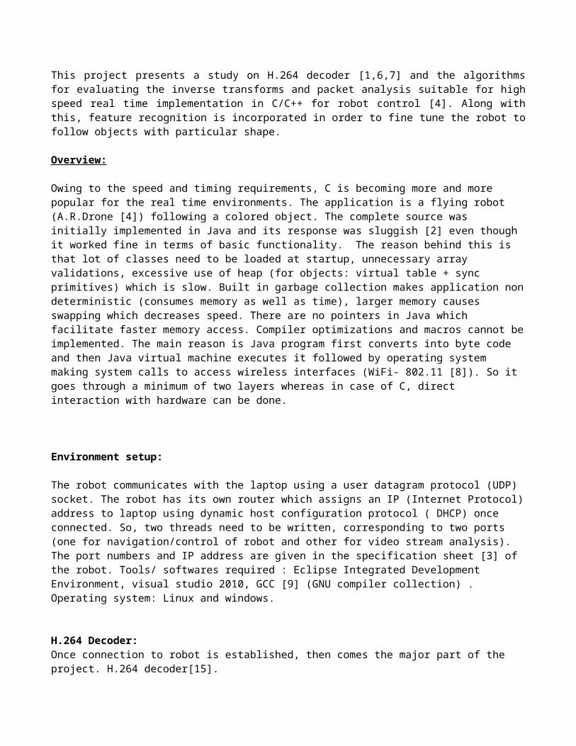
reason is Java program first converts into byte code and then Java virtual machine executes it followed by operating system making system calls to access wireless interfaces (WiFi- 802.11 [8]). So it goes through a minimum of two layers whereas in case of C, direct interaction with hardware can be done.
Environment setup:
The robot communicates with the laptop using a user datagram protocol (UDP) socket. The robot has its own router which assigns an IP (Internet Protocol) address to laptop using dynamic host configuration protocol ( DHCP) once connected. So, two threads need to be written, corresponding to two ports (one for navigation/control of robot and other for video stream analysis). The port numbers and IP address are given in the specification sheet [3] of the robot. Tools/ softwares required : Eclipse Integrated Development Environment, visual studio 2010, GCC [9] (GNU compiler collection) . Operating system: Linux and windows.
H.264 Decoder:Once connection to robot is established, then comes the major part of the project. H.264 decoder[15].But before proceeding with the decoder implementation, the encoder implementation is studied to facilitate correct decoding strategy.
An image is split in groups of blocks (GOB), which correspond to 16-lines-height parts of theimage, split as shown in fig1.
Fig1. Image (left) decomposed into GOBs [3] (right) Each GOB is split into macroblocks (fig2), which represent a 16x16 image.

Fig2. Structure of each GOB [3]
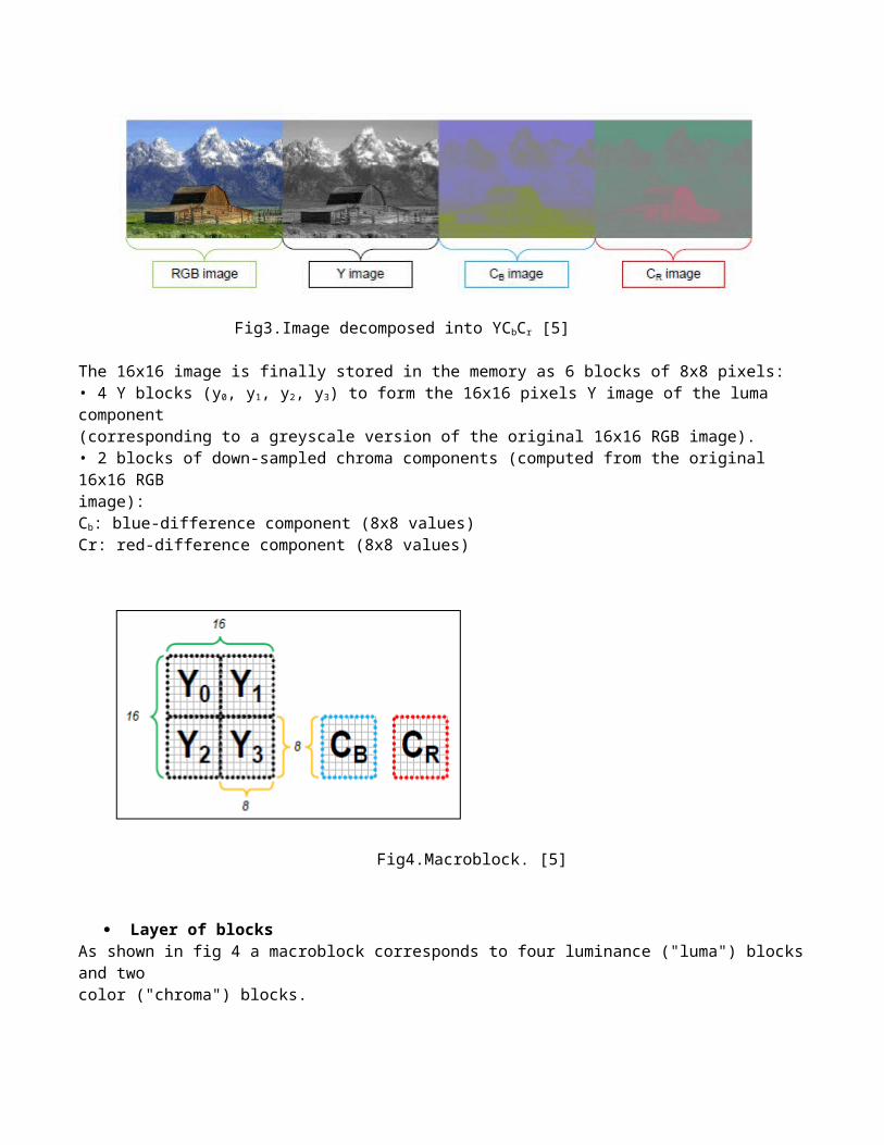
Each macroblock contains information of a 16x16 image, in YCbCr [5] format, type 4:2:0 (fig4)
Fig3.Image decomposed into YCbCr [5]
The 16x16 image is finally stored in the memory as 6 blocks of 8x8 pixels:• 4 Y blocks (y0, y1, y2, y3) to form the 16x16 pixels Y image of the luma component(corresponding to a greyscale version of the original 16x16 RGB image).• 2 blocks of down-sampled chroma components (computed from the original 16x16 RGBimage):Cb: blue-difference component (8x8 values)Cr: red-difference component (8x8 values)
Fig4.Macroblock. [5]
Layer of blocksAs shown in fig 4 a macroblock corresponds to four luminance ("luma") blocks and twocolor ("chroma") blocks.
Step 1: Each 8x8 block of the current macroblock is transformed by DCT [19].
Step 2: Each element of the transformed 8x8 block is quantized.
Step 3: The block 8x8 is then zigzag reordered.
Step 4: The block 8x8 is then encoded using UVLC (universal variable length coding). The complete process is shown in fig6.
Fig6. Modified JPEG [3]This is followed by specific block entropy-coding.
7.2.3 P264 codec overview [3]
P264 [3] is a simplified H.264 baseline profile [15]. It uses I and P frame types but not the B frame type as shown in the fig 7 which is similar to H.264. Its motion compensation precision is 1 pixel as opposed

to H.264’s motion compensation precision (1/4 pixel). The entropy coding used in P264 is RLE coupled with UVLC ,where as in H.264 it is CAVLC.
Fig 7. P264 Vs H.264 [3]I FrameAn I frame is a complete frame. No reference to any previous frame is needed to decode it. LikeH.264, P264 makes a spatial prediction for each macroblock based on the neighboring pixels.
Several mode are available for I macroblock:• intra 16x16 - a prediction is made over the 16x16 macroblock.• intra 4x4 - the macroblock is divided into 16 4x4 blocks. Each 4x4 block has its own intraprediction
Once the intra prediction is done, it is subtracted from the current macroblock. The residualdata is then processed with classical steps : transform, quantization and entropy coding.
Luma intra 16x16 prediction
4 modes are available (fig8):• VERTICAL - extends the 16 upper neighbor pixels over the all 16x16 macroblock• HORIZONTAL - extends the 16 left neighbor pixels over the all 16x16 macroblock• DC - fills the 16x16 block with the mean of the 16 upper and the 16 left neighbor pixels• PLANE - makes interpolation of the 16 upper and the 16 left neighbor pixels
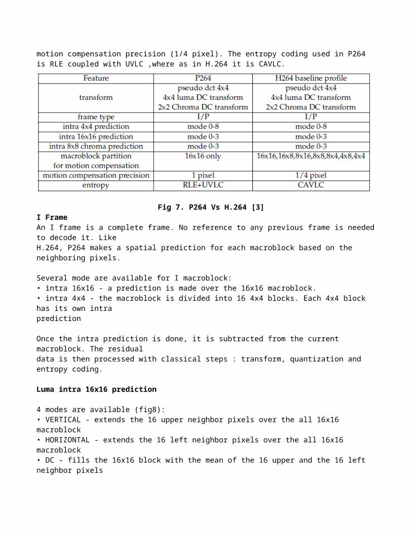
Fig 8. Luma intra 16x16 prediction modes [3]
Luma intra 4x4 prediction
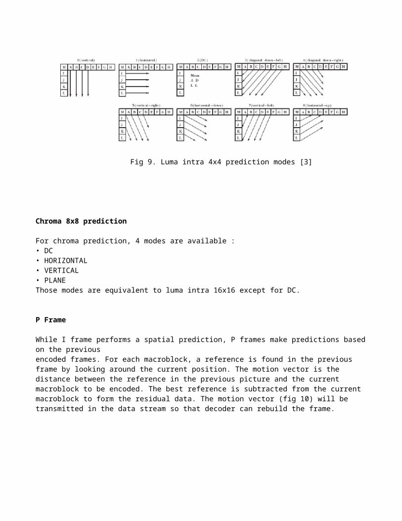
9 modes are available (fig9):• VERTICAL_4x4_MODE• HORIZONTAL_4x4_MODE• DC_4x4_MODE• DIAGONAL_DL_4x4_MODE• DIAGONAL_DR_4x4_MODE• VERTICAL_RIGHT_4x4_MODE• HORIZONTAL_DOWN_4x4_MODE• VERTICAL_LEFT_4x4_MODE• HORIZONTAL_UP_4x4_MODE
Fig 9. Luma intra 4x4 prediction modes [3]

Chroma 8x8 prediction
For chroma prediction, 4 modes are available :• DC• HORIZONTAL• VERTICAL• PLANEThose modes are equivalent to luma intra 16x16 except for DC.
P Frame
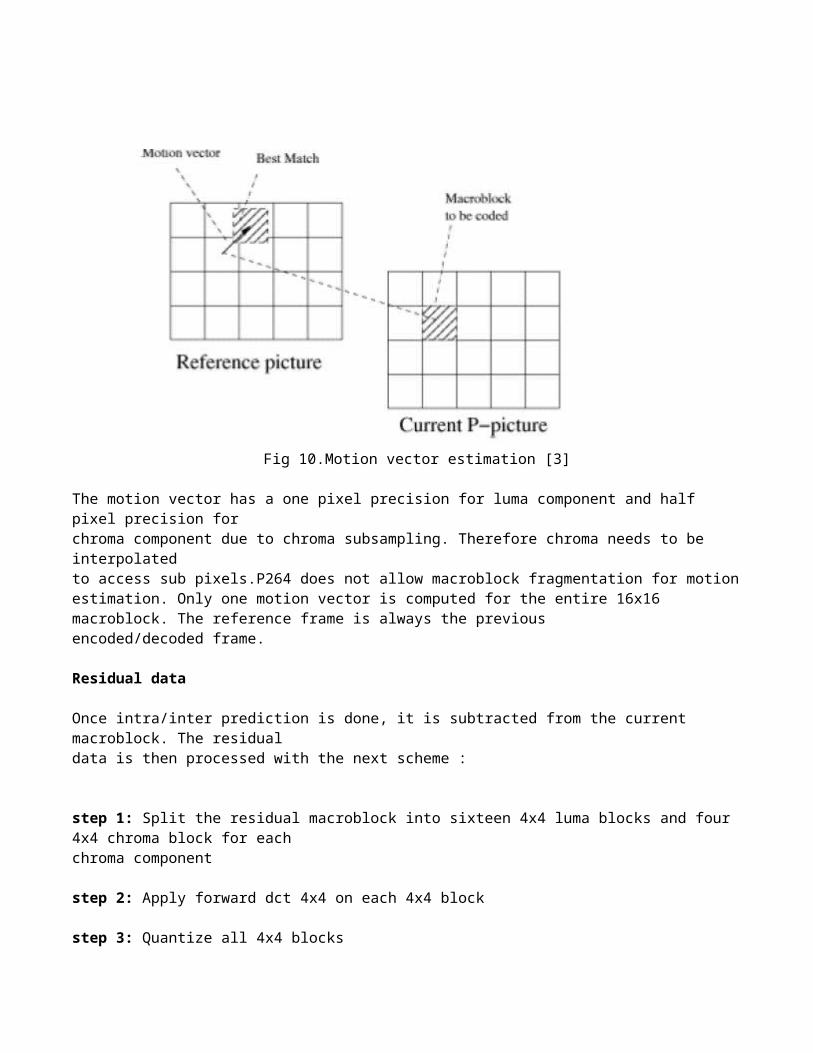
While I frame performs a spatial prediction, P frames make predictions based on the previousencoded frames. For each macroblock, a reference is found in the previous frame by looking around the current position. The motion vector is the distance between the reference in the previous picture and the current macroblock to be encoded. The best reference is subtracted from the current macroblock to form the residual data. The motion vector (fig 10) will be transmitted in the data stream so that decoder can rebuild the frame.
Fig 10.Motion vector estimation [3]
The motion vector has a one pixel precision for luma component and half pixel precision forchroma component due to chroma subsampling. Therefore chroma needs to be interpolatedto access sub pixels.P264 does not allow macroblock fragmentation for motion estimation. Only one motion vector is computed for the entire 16x16 macroblock. The reference frame is always the previousencoded/decoded frame.
Residual data
Once intra/inter prediction is done, it is subtracted from the current macroblock. The residualdata is then processed with the next scheme :
step 1: Split the residual macroblock into sixteen 4x4 luma blocks and four 4x4 chroma block for eachchroma component
step 2: Apply forward dct 4x4 on each 4x4 block
step 3: Quantize all 4x4 blocks
step 4: If current macroblock is encoded using a luma 16x16 prediction, collect all DC coefficientsof each 4x4 luma block and apply a Hadamard transformation [12]
step 5: For each chroma component collect the 4 chroma DC values and perform a 2x2Hadamard transform.
step 6: Zigzag all AC blocks
step 7: Entropy encoding – Mix of run length coding [13] and Huffman coding [14].
In intra 4x4 coding, for each 4x4 block, the intra prediction is determined first then theresidual 4x4 block is processed from step 1 to step 3. Then the 4x4 block is reconstructed inorder to have the correct neighboring pixels for the next 4x4 block intra prediction.The order for luma (Y) and chroma (C) 4x4 block encoding is shown in fig 11.
Fig 11. Order of luma and chroma encoding [3]
The encoder process is summarized in the block diagram (fig 12.a). This is performed by the hardware.
In the decoder entropy decoder entropy decoding, MV is not shown. MV is needed in the motion compensation block.
Fig 12. The block diagram of H.264 algorithm [15](a) Encoder (b) Decoder
Transport layer
This section describes how the final data stream is generated.For each picture, data correspond to an image header followed by groups of data blocks and anending code (EOS, end of sequence).
Transform &Quantization
MotionEstimation
MotionCompensation
PictureBuffering
EntropyCoding
IntraPrediction
Intra/Inter ModeDecision
Inverse Quantization& Inverse Transform
DeblockingFilter
+
-
++
Video Input
Bit streamOutput
(a) encoder
MotionCompensation
PictureBuffering
EntropyDecoding
IntraPrediction
Intra/Inter ModeSelection
Inverse Quantization& Inverse Transform
DeblockingFilter+
+Bit stream Input Video
Output
(b) decoder

The composition of each block-layer is shown in fig 13.
Fig 13. Block composition [3]

Picture start code (PSC) (22 bits)UVLC start with a PSC (Picture start code) is 22 bits long:0000 0000 0000 0000 1 00000P264 PSC is:0000 0000 0000 0001 0 00000A PSC is always byte aligned.
Picture format (PFORMAT) (2 bits)The second information is the picture format which can be one of the following: Common intermediate format (CIF) or Video graphics array (VGA)• 00: forbidden• 01: CIF• 10: VGA
Picture resolution (PRESOLUTION) (3 bits)Picture resolution which is used in combination with the picture format (3 bits)• 000: forbidden• 001: for CIF it means sub-QCIF (Quarter CIF)• 010: for CIF it means QCIF• 011: for CIF it means CIF• 100: for CIF it means 4-CIF• 101: for CIF it means 16-CIF
Picture type (PTYPE) (3 bits)Picture type:• 000: INTRA picture• 001: INTER picture
Picture quantizer (PQUANT) (5/6 bits)UVLC codec: The PQUANT code is a 5-bits-long word. The reference of quantizer for the picturethat range from 1 to 30.P264 codec: The PQUANT code is a 6-bits-long word and range from 0 to 63;
Picture frame (PFRAME) (32 bits)The frame number (32 bits).
Group of block start code (GOBSC) (22 bits)Each GOB starts with a GOBSC (Group of block start code) which is 22 bits long:uvlc codec :0000 0000 0000 0000 1xxx xxp264 codec :0000 0000 0000 0001 0xxx xxA GOBSC is always a byte aligned. The least significant bytes represent the blockline number.
Group of block quantizer (GOBQUANT) (5/6 bits)Equivalent to PQUANT for the current GOB.
UVLC macroblocks LayerData for each macroblock corresponding to header of macroblock followed by data of macroblock.

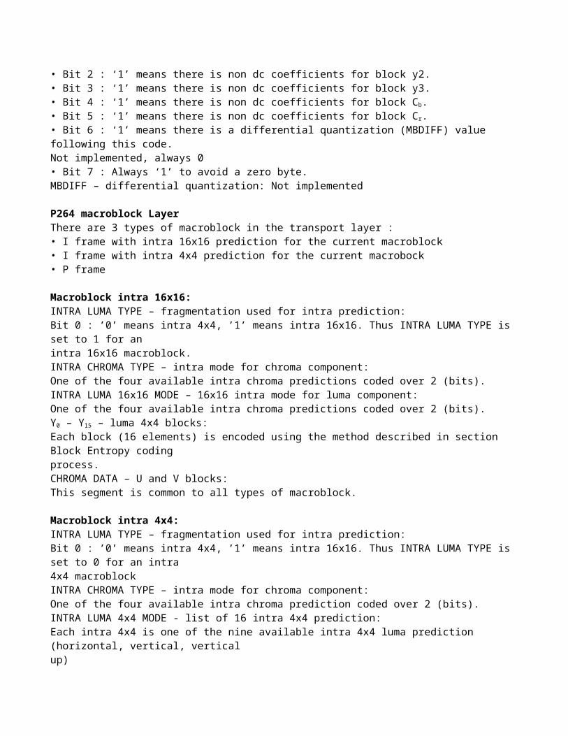
MBC - Coded macroblock bit:• Bit 0 : ‘1’ means there is a macroblock / ‘0’ means macroblock is all zero.• If MBC is 0, the following fields are omitted.MBDES - macroblock description code:• Bit 0 : ‘1’ means there is non dc coefficients for block y0.• Bit 1 : ‘1’ means there is non dc coefficients for block y1.• Bit 2 : ‘1’ means there is non dc coefficients for block y2.• Bit 3 : ‘1’ means there is non dc coefficients for block y3.• Bit 4 : ‘1’ means there is non dc coefficients for block Cb.• Bit 5 : ‘1’ means there is non dc coefficients for block Cr.• Bit 6 : ‘1’ means there is a differential quantization (MBDIFF) value following this code.Not implemented, always 0• Bit 7 : Always ‘1’ to avoid a zero byte.MBDIFF – differential quantization: Not implemented
P264 macroblock LayerThere are 3 types of macroblock in the transport layer :• I frame with intra 16x16 prediction for the current macroblock• I frame with intra 4x4 prediction for the current macrobock• P frame
Macroblock intra 16x16:INTRA LUMA TYPE – fragmentation used for intra prediction:Bit 0 : ’0’ means intra 4x4, ’1’ means intra 16x16. Thus INTRA LUMA TYPE is set to 1 for anintra 16x16 macroblock.INTRA CHROMA TYPE – intra mode for chroma component:One of the four available intra chroma predictions coded over 2 (bits).INTRA LUMA 16x16 MODE – 16x16 intra mode for luma component:One of the four available intra chroma predictions coded over 2 (bits).Y0 – Y15 – luma 4x4 blocks:Each block (16 elements) is encoded using the method described in section Block Entropy codingprocess.CHROMA DATA – U and V blocks:This segment is common to all types of macroblock.
Macroblock intra 4x4:INTRA LUMA TYPE – fragmentation used for intra prediction:Bit 0 : ’0’ means intra 4x4, ’1’ means intra 16x16. Thus INTRA LUMA TYPE is set to 0 for an intra4x4 macroblockINTRA CHROMA TYPE – intra mode for chroma component:One of the four available intra chroma prediction coded over 2 (bits).INTRA LUMA 4x4 MODE - list of 16 intra 4x4 prediction:Each intra 4x4 is one of the nine available intra 4x4 luma prediction (horizontal, vertical, verticalup)Each element of the list is coded using a prediction based on the neighboring predictions. Ifthe prediction is correct, the element is coded using only 1 bit. If the prediction is false 4 bitsare used. DC Y – list of 16 DC value:DC Y is a list of 16 elements which gather DC values from the 16 4x4 blocks of the currentmacroblock. This list is written in the data stream using the block-encoding method.
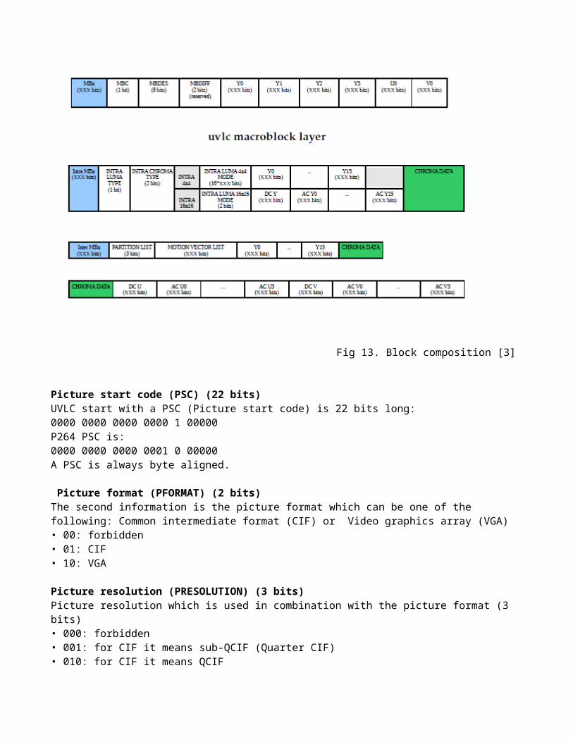
AC Yx – block of AC coeff:Each AC block (15 elements) is encoded with the block-encoding method.CHROMA DATA – U and V blocks:This segment is common to all type of macroblocks.
Inter macroblock :PARTITION LIST – list of mb subdivision for motion estimation:Always read as ’000’.
MOTION VECTOR LIST – list of motion vector associated to each partition:There is only one motion vector per macroblock. The vector is not put in the stream directly. Apredicted motion vector for the current macroblock is determined with the already transmittedneighboring motion vector. The difference between the prediction and the real motion vectoris written in the data stream.The x component is transmitted before the y component. Each component is written with the level-encoding method.Y0 – Y15 – luma 4x4 blocks:Each block (16 elements) is encoded using the method described in section Block Entropy codingprocess.
CHROMA DATA – U and V blocks:This segment is common to all type of macroblocks.
Chroma data:DC U – list of 4 DC value:DC U is a list which contains the DC values from each chroma 4x4 block. This list is encodedwith the block-encoding method.AC Ux - block of AC coeff:Each AC block (15 elements) is encoded with the block-encoding method.DC V: Same as DC UAC Vx: Same as AC Ux
End of sequence (EOS) (22 bits)The end of sequence (EOS) which is 22 bits long :0000 0000 0000 0001 0111 11
Decoder:
The main purpose of this project is to implement the decoder fig 12(b). Steps:
1. Entropy decoding2. Inverse zigzag, followed by inverse quantization and inverse transformation. 3. Forming the picture by the picture format given in fig 11.4. Extracting the motion vector information from the packet followed by motion compensation.5. Finally getting the video.

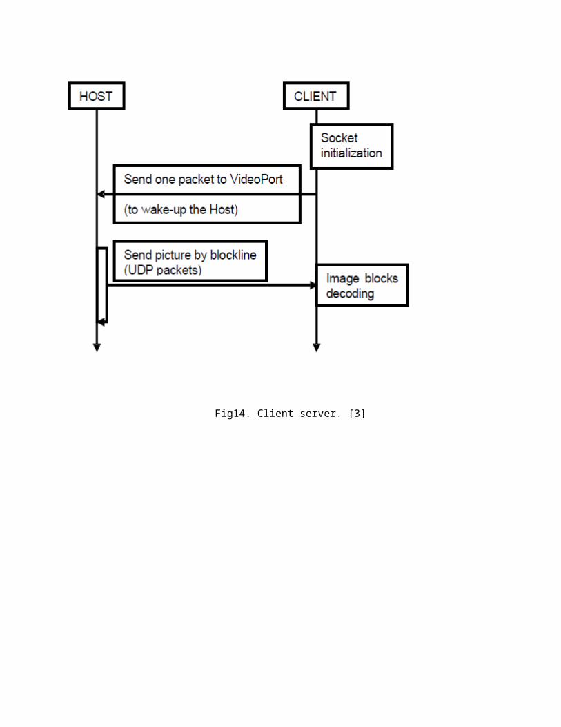
Initiating the video stream
To start receiving the video stream, a client just needs to send a UDP packet on the drone videoport. The drone will stop sending data if it cannot detect any network activity from its client (fig 14).
Fig14. Client server. [3]
Hardware:
Fig15. Robot hardware [3]A.R.Drone is a quadrotor (fig15). The mechanical structure comprises four rotors attached to the fourends of a crossing to which the battery and the RF hardware are attached.Each pair of opposite rotors is turning the same way. One pair is turning clockwise and theother pair anti-clockwise (fig 16).

Fig16.Drone movements [4]Sensors:
Fig17.Sensors. [3]Batteries:The AR.Drone uses a charged 1Ah, 11.1V LiPo (Lithium polymer) batteries to fly. While flying the battery voltage decreases from full charge (12.5 Volts) to low charge (9 Volts).
Motion sensorsThe AR.Drone has many motions sensors. They are located below the central hull.The AR.Drone features a 6 DOF (Degrees of freedom), MEMS (Microelectromechanical systems) based, miniaturized inertial measurement unit. It providesthe software with pitch, roll and yaw measurements.Inertial measurements are used for automatic pitch, roll and yaw stabilization and assistedtilting control. They are needed for generating realistic augmented reality effects.An ultrasound telemeter provides with altitude measures for automatic altitude stabilization

and assisted vertical speed control.A camera aiming towards the ground provides with ground speed measures for automatichovering and trimming.
Video streaming:The frontal camera is a CMOS sensor with a 90 degrees angle lens.The AR.Drone automatically encodes and streams the incoming images to the host device.The video stream frame rate is set to 15 Hz.
Algorithm:
Initialize the UDP sockets for streaming, sending commands and accepting navigation data.
Create a thread for streaming the video from the AR.Drone.
Create a thread for sending commands to the AR.Drone thus controlling its movements.
Create a thread for monitoring the keyboard.
Create a thread for accepting the navigation data from the AR.Drone.
Create an infinite loop.
Poll the keyboard event.
Update the image on the screen.
If the start key is pressed, set the robot into hover mode by sending the hover command to it.(The robot now waits for the red ball to show up in front of its frontal camera)
If ball is not there, the robot stays still in the same position until the stop key is pressed.
If the robot’s camera gets the ball, it uses open source computer vision (OpenCV []) to recognize the ball. At the same time the data coming to the laptop through the video socket is analyzed. The inverse transform is calculated followed by motion compensation and estimation. This video is shown on the screen.
Then the centroid of the ball is calculated.
As the robot moves, the difference between the updated position and the previous position is calculated (The movement is restricted to the horizontal direction).
If the difference is positive, it is inferred that the ball has moved to the right.
So the command is sent to move the robot to the right side with the intention to reduce the difference.
If the difference is negative, it is inferred that the ball has moved to the left.
So the command is sent to move the robot to the left side.
Finally, once the stop key is pressed, the robot is brought down by sending the command.
Programs:
A simple program to establish connection with the A.R. Drone:
static void send_command(){
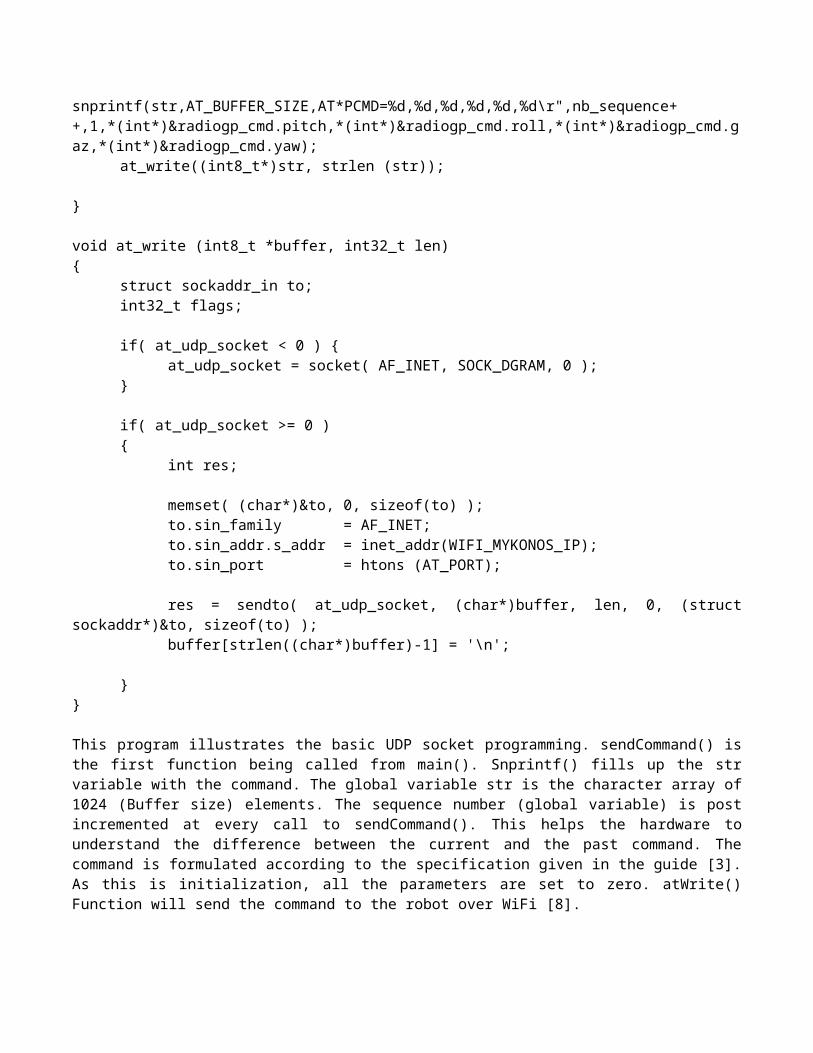
snprintf(str,AT_BUFFER_SIZE,AT*PCMD=%d,%d,%d,%d,%d,%d\r",nb_sequence++,1,*(int*)&radiogp_cmd.pitch,*(int*)&radiogp_cmd.roll,*(int*)&radiogp_cmd.gaz,*(int*)&radiogp_cmd.yaw);
at_write((int8_t*)str, strlen (str));
}
void at_write (int8_t *buffer, int32_t len){
struct sockaddr_in to;int32_t flags;
if( at_udp_socket < 0 ) {at_udp_socket = socket( AF_INET, SOCK_DGRAM, 0 );
}
if( at_udp_socket >= 0 ){
int res;
memset( (char*)&to, 0, sizeof(to) );to.sin_family = AF_INET;to.sin_addr.s_addr = inet_addr(WIFI_MYKONOS_IP); to.sin_port = htons (AT_PORT);
res = sendto( at_udp_socket, (char*)buffer, len, 0, (struct sockaddr*)&to, sizeof(to) );buffer[strlen((char*)buffer)-1] = '\n';
}
}
This program illustrates the basic UDP socket programming. sendCommand() is the first function being called from main(). Snprintf() fills up the str variable with the command. The global variable str is the character array of 1024 (Buffer size) elements. The sequence number (global variable) is post incremented at every call to sendCommand(). This helps the hardware to understand the difference between the current and the past command. The command is formulated according to the specification given in the guide [3]. As this is initialization, all the parameters are set to zero. atWrite() Function will send the command to the robot over WiFi [8].

A datagram socket facilitates the data to be sent using the UDP protocol. As the socket requires IP address and port number, it is being filled up in the structure ‘to’ of type sockaddr_in. send_to() function finally ships the data to the process running on the server (here A.R. Drone) controlling the commands. The A.R. Drone accepts commands from the port number 5556. The IP address of A.R. Drone is 192.168.1.1. The functions socket(), sendto() are defined in the network header files of linux.
Then this program is enhanced to create a hovering application. It follows the instructions given in the guide [3] coupled with the socket programming.
The video stream is available on the port number 5555. So, the current research is focused on the incoming bit stream analysis. Consequently, inverse transformation followed by the motion estimation and motion compensation algorithms would be implemented and finally the video would be displayed on the screen.
Prior to this, the application needs to be multithreaded in order to simultaneously handle streaming, navigation, control and monitoring keyboard. This needs extensive study of portable operating system interface (POSIX [16]) threads.
The keyboard monitoring is facilitated by simple direct media layer (SDL [17]) libraries. This library also has application programming interface (APIs) to display the images and video.
Finally the object recognition would be done using OpenCV [18] library. So the current research is involved in the study of POSIX threads, SDL and OpenCV libraries.
Results:
The video packets sent by robot to the laptop in the H.264 format were decoded successfully. Then the feature recognition was carried out to extract circle using openCV. Correspondingly, the robot was navigated to follow the object.
Significant performance (in terms of operation speed) improvements are achieved with respect to older java implementation. Thus, C/ C++ are the obvious choices for implementing the real time control algorithms.
These are the images decoded:
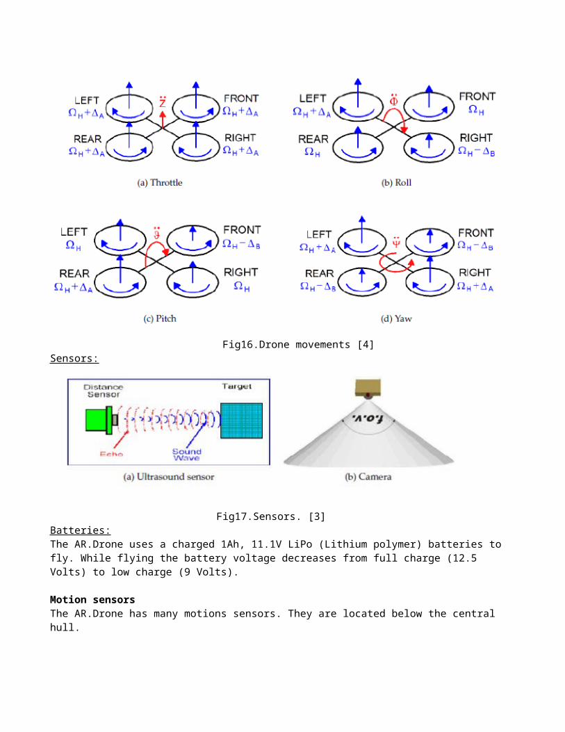
Fig 17. Startup
Fig 18. Person holding the red circular object in front of robot.

Fig 19. Red circular object highlighted to facilitate the pattern recognition
Fig 20. The robot following the red circular object.
The video is uploaded on the link http://omega.uta.edu/~ssg8850/test.avi

Further improvements:
The control algorithm fails sporadically. This leads the robot to crash. This has to be fixed by implementing PID control and lowering the speed.
Applications:
Reality games: A.R. Drone can be controlled by joystick or smart phones to play video games.
Advertising: A.R. Drone can be used for online advertising.
Medical and 3D vision: Photos of patients from various angles can be captured by the frontal as well as bottom camera.
References:
[1] F. Pescador, M.J.Garrido, C.Sanz, E.Juarez, M.C.Rodriguez and D.Samper, “A real-time H.264 MP decoder based on a DM642 DSP”, 14th IEEE International Conference on Electronics, Circuits and Systems, Madrid, Spain, ICECS 2007, Vol. 11, pp.1248 – 1251, Dec. 2007.[2] Java is slower than C: http://www.jelovic.com/articles/why_Java_is_slow.htm[3] A.R. Drone Developer’s guide: https ://projects.ardrone.org/login?back_url=http%253A%252F %252Fprojects.ardrone.org%252Fattachments%252Fdownload%252F365%252FARDrone_SDK_1_7_Developer_Guide.pdf [4] A.R.Drone http://ardrone.parrot.com/parrot-ar-drone/usa/ [5] Y-Cb-Cr format: http://en.wikipedia.org/wiki/YCbCr[6] H.264 Reference : http://en.wikipedia.org/wiki/H.264/MPEG-4_AVC[7] W.T.Staehler and A.A.Susin, “Real-time 4x4 intraframe prediction architecture for a H.264 decoder.” UFRGS, Alegre Telecommunications Symposium, 2006 International, pp. 416 – 421, Sept. 2006 [8]Wifi wiki : http://en.wikipedia.org/wiki/Wi-Fi[9] GCC wiki : http://en.wikipedia.org/wiki/GNU_Compiler_Collection[10] Introduction to make (linux make for building C/C++ sources) http://linuxdevcenter.com/pub/a/linux/2002/01/31/make_intro.html[11] JPEG wiki: http://en.wikipedia.org/wiki/JPEG[12] Shih-Tse Wei, Chia-Wei Tien, Bin-Da Liu and Jar-Ferr Yang, “Adaptive Truncation Algorithm for Hadamard-Transformed H.264/AVC Lossless Video Coding”. IEEE Transactions on Circuits and Systems for Video Technology, Vol. 21, pp. 538 - 549, May 2011. [13] Runlength coding wiki: http://en.wikipedia.org/wiki/Run-length_encoding[14] Huffman coding wiki: http://en.wikipedia.org/wiki/Huffman_coding
[15] Soon-kak Kwon*, A. Tamhankar and K.R. Rao, “ Emerging H.264/AVC video coding standard”, J. Visual Communication and Image Representation, vol. 17, pp.186-216, April 2006.http://www-ee.uta.edu/dip/Courses/EE5351/ee5351.htm- H.264 review [16] POSIX Thread wiki: http://en.wikipedia.org/wiki/POSIX
[17]SDL wiki: http://en.wikipedia.org/wiki/Simple_DirectMedia_Layer[18]OpenCV wiki: http://en.wikipedia.org/wiki/OpenCV[19]DCT wiki: http://en.wikipedia.org/wiki/Discrete_cosine_transform