Embed Size (px)
Citation preview
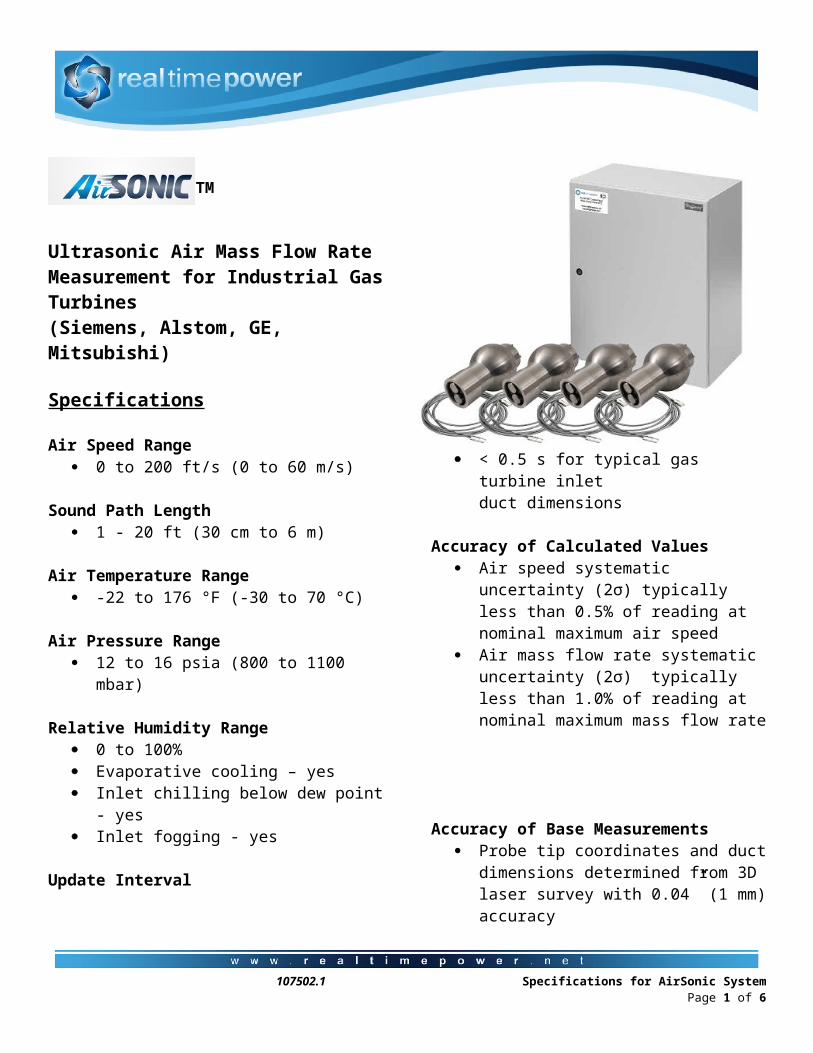
TM
Ultrasonic Air Mass Flow Rate Measurement for Industrial Gas Turbines (Siemens, Alstom, GE, Mitsubishi) Specifications
Air Speed Range 0 to 200 ft/s (0 to 60 m/s)
Sound Path Length 1 - 20 ft (30 cm to 6 m)
Air Temperature Range -22 to 176 °F (-30 to 70 °C)
Air Pressure Range 12 to 16 psia (800 to 1100 mbar)
Relative Humidity Range 0 to 100% Evaporative cooling – yes Inlet chilling below dew point - yes Inlet fogging - yes
Update Interval < 0.5 s for typical gas turbine inlet
duct dimensions
Accuracy of Calculated Values Air speed systematic uncertainty (2σ)
typically less than 0.5% of reading at nominal maximum air speed
Air mass flow rate systematic uncertainty (2σ) typically less than 1.0% of reading at nominal maximum mass flow rate
Accuracy of Base Measurements Probe tip coordinates and duct dimensions
determined from 3D laser survey with 0.04” (1 mm) accuracy
Sound pulse flight times measured using oven controlled crystal oscillator (OCXO) to 0.5 µs accuracy
Static air pressure measured to 0.1% accuracy (0.05% optional)
Principle of Measurement Air mass flow rate = air mass flux
x duct area x duct factor Air mass flux = air speed x air density Air speed: calculated from sound pulse
flight times and probe tip coordinates Air density: calculated from sonic velocity
and static air pressure Sonic velocity: calculated from sound pulse
flight times and probe tip coordinates Duct area: determined from duct survey Duct factor: determined from CFD analysis
107502.1 Specifications for AirSonic System Page 1 of 5
Data CommunicationsAll AirSonic data is accessible via OPC or MODBUS TCP. The signals include:
Air density (lb/ft3) Air flow angle (°) Air mass flux (lb/s/ft2) Air mass flow rate (lb/s) Air pressure (psia) Air speed (ft/s) Air velocities (ft/s) Air volumetric flow rate (ft3/s) Flight times (ms) Sonic Velocity (ft/s)
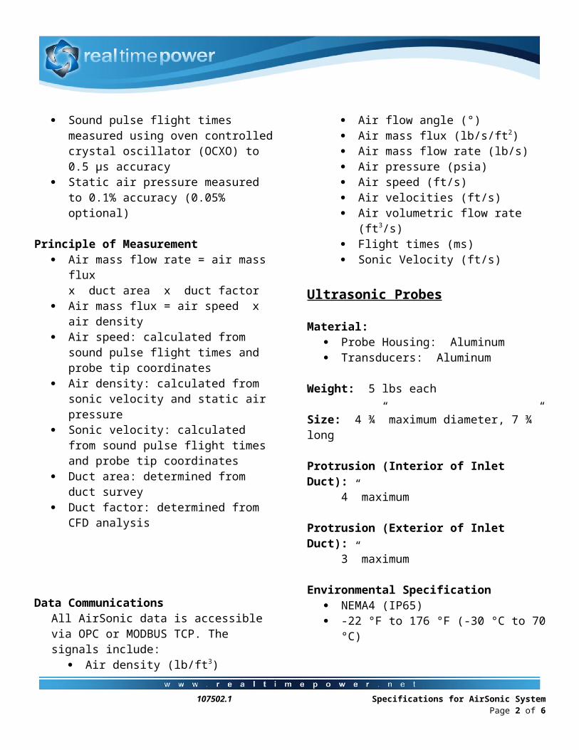
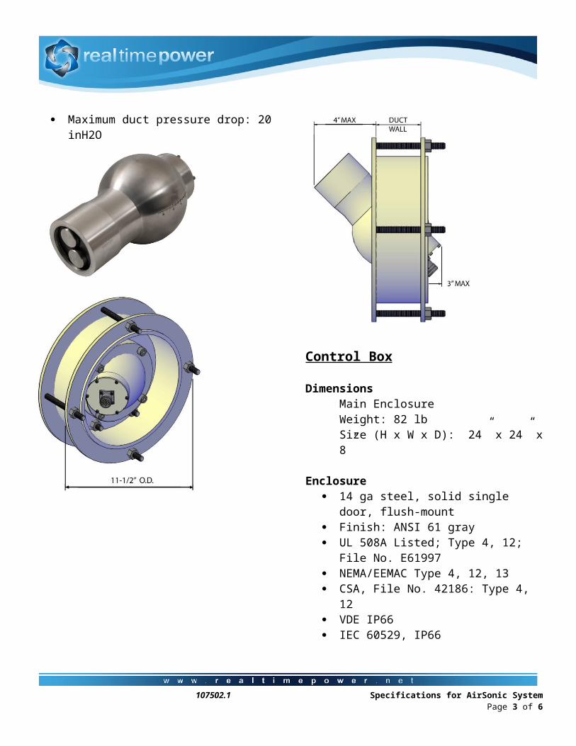
Ultrasonic Probes
Material: Probe Housing: Aluminum Transducers: Aluminum
Weight: 5 lbs each
Size: 4 ¾” maximum diameter, 7 ¾” long
Protrusion (Interior of Inlet Duct): 4” maximum
Protrusion (Exterior of Inlet Duct): 3” maximum
Environmental Specification NEMA4 (IP65) -22 °F to 176 °F (-30 °C to 70 °C) Maximum duct pressure drop: 20 inH2O
107502.1 Specifications for AirSonic System Page 2 of 5
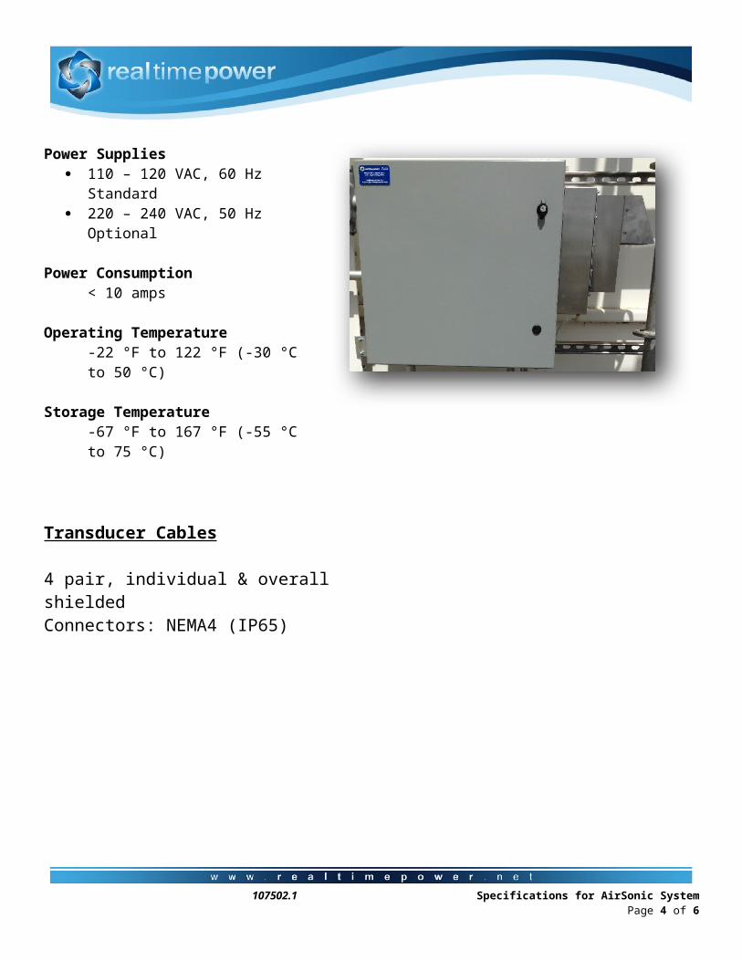
Control Box
DimensionsMain Enclosure Weight: 82 lbSize (H x W x D): 24” x 24” x 8”
Enclosure 14 ga steel, solid single door, flush-mount Finish: ANSI 61 gray UL 508A Listed; Type 4, 12; File No. E61997 NEMA/EEMAC Type 4, 12, 13 CSA, File No. 42186: Type 4, 12 VDE IP66 IEC 60529, IP66
Power Supplies 110 – 120 VAC, 60 Hz Standard 220 – 240 VAC, 50 Hz Optional
Power Consumption< 10 amps
Operating Temperature-22 °F to 122 °F (-30 °C to 50 °C)
Storage Temperature-67 °F to 167 °F (-55 °C to 75 °C)
Transducer Cables
4 pair, individual & overall shieldedConnectors: NEMA4 (IP65)
107502.1 Specifications for AirSonic System Page 3 of 5
Example Locations For Gas Turbine Ducts
Rectangular
Siemens 501G
Mitsubishi 501G Inlet Duct Probe Locations
GE 7FA
107502.1 Specifications for AirSonic System Page 4 of 5

107502.1 Specifications for AirSonic System Page 5 of 5