Embed Size (px)
Citation preview
Multilayer supercapacitor threads for woven flexible circuitsFulian Qiu1, David Harrison1
1College of Engineering, Design and Physical Sciences, Brunel University, Uxbridge, UB8 3PH, UK
AbstractPurpose – Wearable electronic devices have emerged which require compact, flexible power storage devices
such as batteries and supercapacitors. Recently energy storage devices have been developed based on
supercapacitor threads. However, current supercapacitor energy storage threads which use electrolytes based on
aqueous gels have a 1V potential window. This is much lower than the voltage required by most electronic
devices. This current contribution presents an approach for fabricating a multilayer supercapacitor working as a
circuit unit , in which series combinations of the multiple layer structures can achieve a higher potential
window, which can better meet the needs of wearable electronic devices.
Design/methodology/approach – Two-capacitive layer thread supercapacitors were fabricated using a semi-
automatic dip coating method by coating two capacitive layers sequentially on a 50 m stainless steel core wire,
each capacitive layer includes ink, aqueous based gel electrolyte and silver conductive paint layers.
Findings – Two capacitive layers of the single thread supercapacitor can work independently, or as combination
circuits – parallel and series. Cyclic voltammograms showed all flexible circuits have high electrochemical
stability. For the case of series circuit configuration, with H3PO4/PVA (Polyvinyl alcohol) gel electrolyte, a
working potential window of 2 V was achieved.
Originality/value - A flexible single thread supercapacitor of multilayer structure, with working voltage above
1 V in H3PO4 / PVA gel electrolyte, has not been reported before. A semi-automatic dip coating setup used to
process the thread supercapacitor has high potential for transfer to an industrial environment for mass
production.
Keywords Flexible circuits, Multilayer supercapacitor, dip coating method, energy storage device,
supercapacitor thread
Paper type Technical paper

Introduction
Developments and applications of portable electronic devices (De Rossi et al., 2005), wearable gadgets (Salvo
et al., 2010), bio/chemical sensors (Shim et al., 2008) and flexible solar cells (Zou et al., 2010) require
comparable energy storage devices such as batteries (NishideOyaizu., 2008) and supercapacitors
(electrochemical double-layer capacitor) (Kang et al., 2012a). Supercapacitors have many advantages over Li
ion batteries with high power density, fast charge-discharge process, easy fabrication, low cost, long life time
and a good safety record. Miniaturised, flexible, light-weight and weaveable thread supercapacitors are of
interest because they may be fully integrated into fabrics. Xu et al reported all-solid-state flexible
supercapacitors based on a carbon/MnO2 (C/M) core–shell fibre structure, with a high electrochemical
performance, including a high rate capability with a scan rate up to 20 V s–1, and high volume capacitance of
2.5 F cm–3. Recently extensive research has focused on 1D fibre supercapacitors as structured in figure 1 /(a, b
& c), In the case of (a), Chinese ink coated nickel wires (Fu et al., 2012) were arranged in parallel, sealed in
PVA gel electrolyte, and the capacitance did not vary with bending angles, which demonstrated the high
flexibility of the device. Electrochemical deposited 3D graphene microfiber (Meng et al., 2013) were twisted in
PVA gel electrolyte to form a stretchable supercapacitor, the device showed high electrochemical stability and
flexibility during spring shape compress- stretch test. Parallel two-fibre supercapacitor integrating with solar
cell fibre has been reported (Fu et al., 2013), the stainless wires coated with polyaniline electrochemically
served as energy storage electrodes. Coaxial fibre supercapacitor made from all-carbon materials (Le et al.,
2013) and Chinese ink coated onto a conducting core wire(Harrison et al., 2013) were examples for the case of
(c), where the PVA gel electrolyte served as a separator between two concentric active layers. These
supercapacitors have a simple structure. For all solid-state 1D supercapacitors (a, b and c), as PVA-H3PO4 was
employed as electrolyte, their applications have been hindered by an intrinsic potential window of 1V, as most
electronic devices operate at above 1V. As Zhao describes in his review of electrolytes, (Zhao et al. 2015),
aqueous electrolytes such as these have the advantages of high-ionic conductivity, low cost, non-flammability,
non-corrosiveness, safety, and convenient assembly in air, compared to organic electrolytes, which are believed
to be less conductive, expensive, usually flammable, and have higher toxicity. (However, adopting an organic
electrolyte, such as propylene carbonate with an organic salt, can give a working voltage of up to 2.5 volts).
Combination circuits of parallel and series supercapacitors (stacked) have also been produced to increase the
working voltage for LED lighting tests (Yuan et al., 2011) as LEDs are operated above 1V.
So far, almost all reported 1D supercapacitors have been made manually, and their length uniformity has been
limited. 1D fibre supercapacitors have a low volume and high flexibility, and a few woven supercapacitors in
fabric structures have been reported (Dalton et al., 2004).
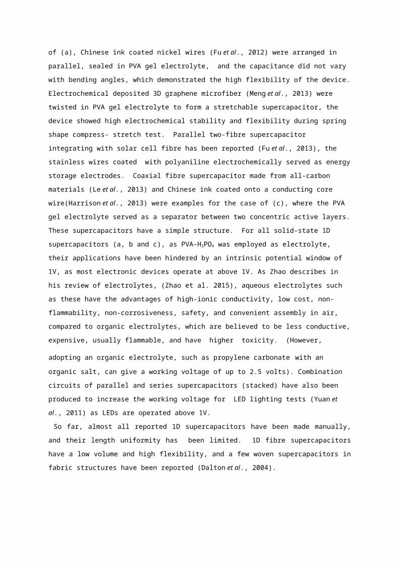
Figure 1 Schematic of fibre supercapacitors (a) two-fibre parallel, (b) two-fibre twisted and (c) one-fibre
coaxial
(a)
(b)
(c)
Here, we report a coaxial multilayer thread supercapacitor. Although a bipolar flat supercapacitor has been
reported (Ng et al., 2009), no coaxial structure multilayer fibre supercapacitor has been attempted. A two-
capacitive-layer single thread supercapacitor was fabricated and characterised, and its capacitances and
electrochemical stability were studied. A semi-automatic dip coating method was employed for the fabrication.
Multilayer thread supercapacitor design and fabrication
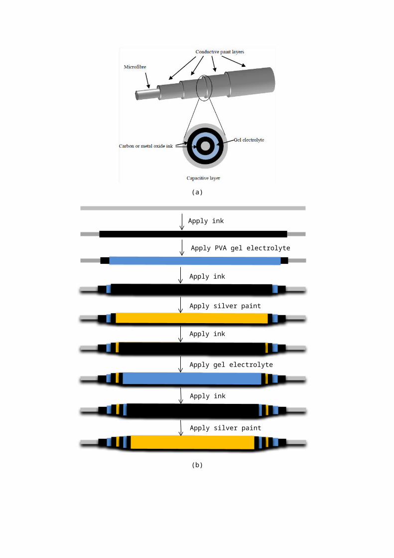
Figure 2a shows the schematic of a multilayer thread supercapacitor. It could be composed of many capacitive
layers on a core conductor; each capacitive layer consisting of ink-gel-ink-conductive paint layers. The ink used
was a suspension of carbon in an aqueous solution. The function of each ink layer was to act as an electrode in
the supercapacitor structure. When a potential window of V Volt is assumed for a single capacitive layer thread
supercapacitor, for a “n” capacitive layers thread supercapacitor as one unit, its potential window would be nV
Volt. For this study, a 50 m stainless steel microwire was employed as the core conductor.
A series of capacitive layers were coated onto the stainless steel microwire sequentially using a semi-
automatic dip coating setup. This setup consists of a multi-speed controlled motor and Perspex discs of a radius
of 1.5 cm or 1 cm diameter with PTFE pipette reservoirs attached. In the centre of the discs and the reservoirs,
eight different sizes of sub-millimetre holes were machined using a laser cutting setup, which allowed the core
wire through, and facilitated the dip coating processes. Holes of different diameters were created for different
coating layers.
A pre-wired bobbin was fixed onto the motor; a small weight was clamped to the bottom end of the core wire,
which kept the wire straight in an up-down alignment. The motor has a two-direction controller which allows
PVA gel electrolyte
Active fibre
PVA Gel electrolyte
Active fibre
Silver paint
Active layer Active fibre
PVA gel electrolyte
the load to move up or down. When the coating process was performed, a drop of coating liquid (slurry) was
applied to the centre of the disc such that the wire moves through it. During the movement of the core wire it
dragged the liquid with it, the solvent vaporised, and a coating layer was formed on the wire. Different coating
layers were coated onto the core microwire sequentially. The thread was pulled first through the disc with the
smallest diameter, to make the first coated layer. Following drying, the thread must be unclamped, and the next
smallest diameter disc used for the subsequent layer. The thickness of each coating layer can be adjusted by the
coating time controlled by motor speed; a motor speed of 0.5 m/minute was used throughout experiment. The
time interval was approximately 5 minutes for the ink and gel electrolyte coatings. This approach currently
results in a relatively lengthy fabrication time of up to 40 minutes for the complete structure. Work is
proceeding with industrial partners to adapt the coating techniques to produce an efficient continuous process.
Multiple coating passes were performed for each of the three active layers and the silver paint layer. Ink, 10 wt
% H3PO4 / 8.3 wt% PVA gel electrolyte, and silver paint were used throughout the experiment for each layer
coating respectively. In order to coat the gel electrolyte uniformly, the first gel electrolyte coating was
conducted using 5 wt% PVA gel.
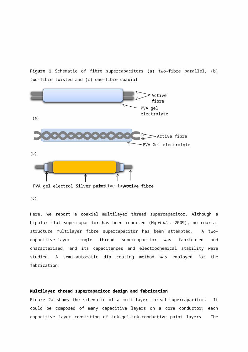
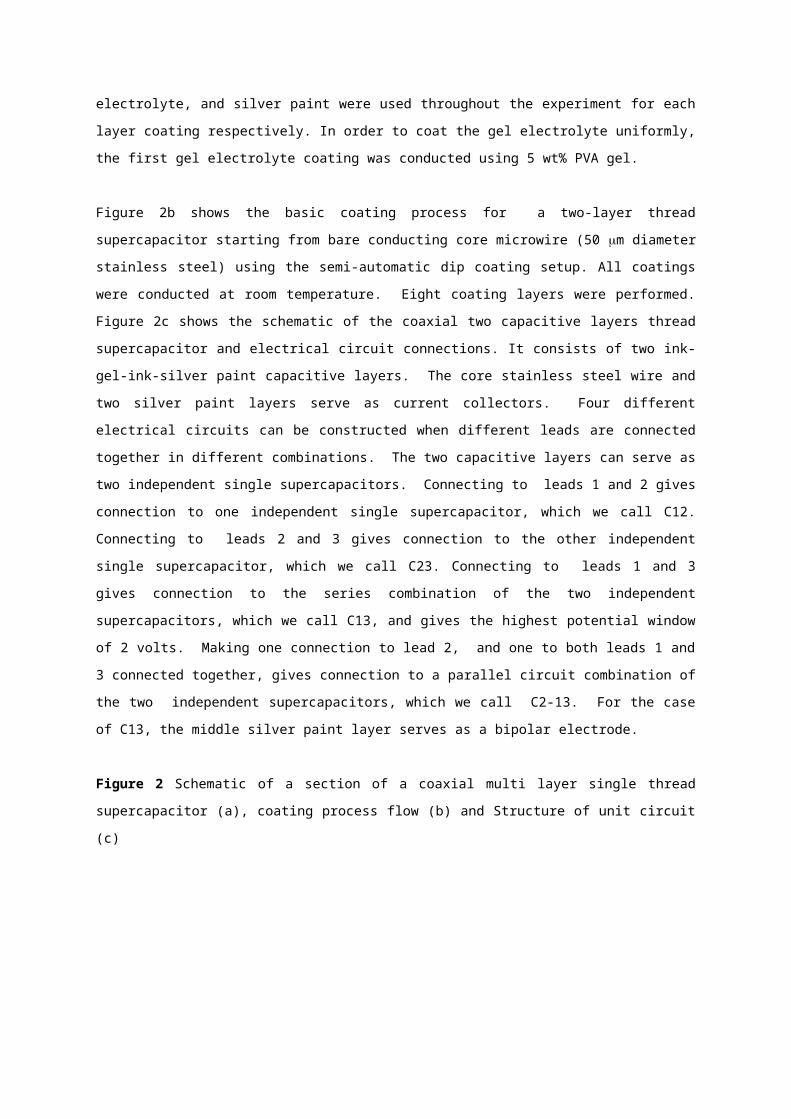
Figure 2b shows the basic coating process for a two-layer thread supercapacitor starting from bare conducting
core microwire (50 m diameter stainless steel) using the semi-automatic dip coating setup. All coatings were
conducted at room temperature. Eight coating layers were performed. Figure 2c shows the schematic of the
coaxial two capacitive layers thread supercapacitor and electrical circuit connections. It consists of two ink-gel-
ink-silver paint capacitive layers. The core stainless steel wire and two silver paint layers serve as current
collectors. Four different electrical circuits can be constructed when different leads are connected together in
different combinations. The two capacitive layers can serve as two independent single supercapacitors.
Connecting to leads 1 and 2 gives connection to one independent single supercapacitor, which we call C12.
Connecting to leads 2 and 3 gives connection to the other independent single supercapacitor, which we call
C23. Connecting to leads 1 and 3 gives connection to the series combination of the two independent
supercapacitors, which we call C13, and gives the highest potential window of 2 volts. Making one connection
to lead 2, and one to both leads 1 and 3 connected together, gives connection to a parallel circuit combination of
the two independent supercapacitors, which we call C2-13. For the case of C13, the middle silver paint layer
serves as a bipolar electrode.
Figure 2 Schematic of a section of a coaxial multi layer single thread supercapacitor (a), coating process flow
(b) and Structure of unit circuit (c)

(a)
(b)
Apply silver paint
Apply ink
Apply gel electrolyte
Apply ink
Apply silver paint
Apply ink
Apply PVA gel electrolyte
Apply ink
(c)
Optical microstructure of a two-layer thread supercapacitor
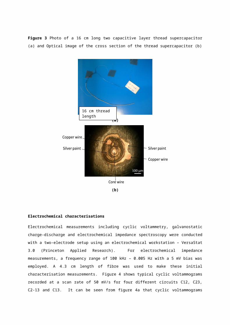
Figure 3a shows the photo of a 16 cm long coaxial two capacitive layers single thread supercapacitor. It has one
stainless steel core wire and two copper wires attached to two silver paint layers as outside connectors. Four
different electrical circuits could be formed between the three wires. The diameter of the supercapacitor is 300
m. Owing to its coaxial, thin and compact structure, the thread supercapacitor has high flexibility. An optical
microscope (Olympus BHM, Trinocular MTV-3 with Nikon Coolpix 990 3.34MP Digital Camera, Japan) was
used to examine the surface morphologies of the cross-section structure of the device. The sample was prepared
by sealing the thread in Araldite® and leaving it overnight for solidification. It is then polished using sandpaper
(P1250, P2500 and P4000) and gamma alumina powder of size from 1m down to 0.025 m, rinsed using
deionised water and methanol, then dried in air. Figure 3b shows a cross section image of the device. As
carbon layers are soft, and the gel electrolyte layer is flexible, the cross section was slightly distorted after
polishing. The coating layers are relatively uniform as shown in figure 3b. Average thicknesses are measured as
18 m, 15 m and 25 m for the ink, gel electrolyte and ink in the inner capacitive layer respectively, and 18
m, 10 m and 20 m for the ink, gel electrolyte and ink in the outer capacitive layer respectively.
Figure 3 Photo of a 16 cm long two capacitive layer thread supercapacitor (a) and Optical image of the cross
section of the thread supercapacitor (b)
16 cm thread length
(a)
(b)
Electrochemical characterisations
Electrochemical measurements including cyclic voltammetry, galvanostatic charge-discharge and
electrochemical impedance spectroscopy were conducted with a two-electrode setup using an electrochemical
workstation – VersaStat 3.0 (Princeton Applied Research). For electrochemical impedance measurements, a
frequency range of 100 kHz – 0.005 Hz with a 5 mV bias was employed. A 4.3 cm length of fibre was used to
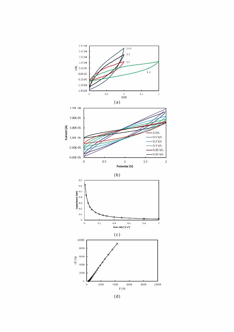
make these initial characterisation measurements. Figure 4 shows typical cyclic voltammograms recorded at a
scan rate of 50 mV/s for four different circuits C12, C23, C2-13 and C13. It can be seen from figure 4a that
cyclic voltammograms were distorted from ideal square-box shape for all cases; this may result from ions’ slow
diffusion in the porous carbon structure and high series resistance. The parallel circuit (C2-13) displayed larger
capacitance CV circled area than those of two single capacitors. The series circuit shows a larger potential
window of 2V. The capacitance can be estimated using the following equation (1) from a cyclic voltammogram
(CV)
C¿ACV
2× v ×V(1)
Where C is the capacitance; ACV, the CV circled area; v, the scan rate and V, the potential window.
Approximated capacitances for four circuits are 0.48, 0.66, 1.22 and 0.54 mF for circuit C12, C 23, C2-13 and
C13 respectively. No faradaic process was observed for all cases of electrical circuits indicating high
electrochemical stability of the device. The stored energy (E) can be calculated using equation (2)
E=0.5CV2 (2)
0.24, 0.33, 0.63 and 1.0 mJ were obtained for C12, C23, C2-13 and C13 respectively, which demonstrated that
the coaxial two capacitive layers thread supercapacitor stores more energy than single capacitors due to a large
potential window. For the C13, as a single thread supercapacitor unit, it demonstrated that, in PVA-H3PO4 gel
electrolyte, the device can be operated within 2 V potential. If compared to a single capacitive layer device of
the same capacitance, its stored energy would be four times bigger based on the equation (2). The energy
density of the series combination capacitor C13 was approximately 0.5 mJ.mm-3
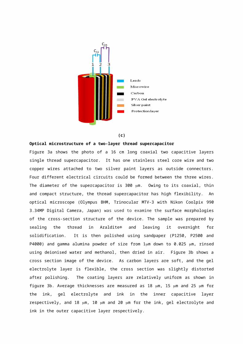
Figure 4b shows typical cyclic voltammograms recorded at six different scan rates (0.01, 0.05, 0.1 0.2, 0.5 and
1.0 V/s) between 0 V and 2 V. It can be seen that the charge current increases with increasing scan rate as
expected. The capacitive rectangular CV shape is distorted, and the distortion becomes more pronounced when
scan rate is increased. This may be explained by the series resistances including that of the gel electrolyte, and
by the diffusion processes in the porous carbon nanostructure which will be more marked at higher scan rates as
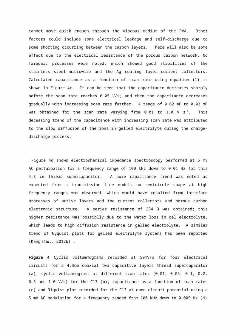
the ions cannot move quick enough through the viscous medium of the PVA. Other factors could include some
electrical leakage and self-discharge due to some shorting occurring between the carbon layers. There will also
be some effect due to the electrical resistance of the porous carbon network. No faradaic processes were noted,
which showed good stabilities of the stainless steel microwire and the Ag coating layer current collectors.
Calculated capacitance as a function of scan rate using equation (1) is shown in Figure 4c. It can be seen that
the capacitance decreases sharply before the scan rate reaches 0.05 V/s; and then the capacitance decreases
gradually with increasing scan rate further. A range of 0.62 mF to 0.03 mF was obtained for the scan rate
varying from 0.01 to 1.0 V s-1. This deceasing trend of the capacitance with increasing scan rate was attributed
to the slow diffusion of the ions in gelled electrolyte during the charge-discharge process.
Figure 4d shows electrochemical impedance spectroscopy performed at 5 mV AC perturbation for a frequency
range of 100 kHz down to 0.01 Hz for this 4.3 cm thread supercapacitor. A pure capacitance trend was noted as
expected from a transmission line model; no semicircle shape at high frequency ranges was observed, which
would have resulted from interface processes of active layers and the current collectors and porous carbon
electronic structure. A series resistance of 234 Ω was obtained; this higher resistance was possiblly due to the
water loss in gel electrolyte, which leads to high diffusion resistance in gelled electrolyte. A similar trend of
Nyquist plots for gelled electrolyte systems has been reported (Kang et al., 2012b) .
Figure 4 Cyclic voltammograms recorded at 50mV/s for four electrical circuits for a 4.3cm coaxial two
capacitive layers thread supercapacitor (a), cyclic voltammograms at different scan rates (0.01, 0.05, 0.1, 0.2,
0.5 and 1.0 V/s) for the C13 (b); capacitance as a function of scan rates (c) and Niquist plot recorded for the C13
at open circuit potential using a 5 mV AC modulation for a frequency ranged from 100 kHz down to 0.005 Hz
(d)
(a)
(b)
(c)
(d)
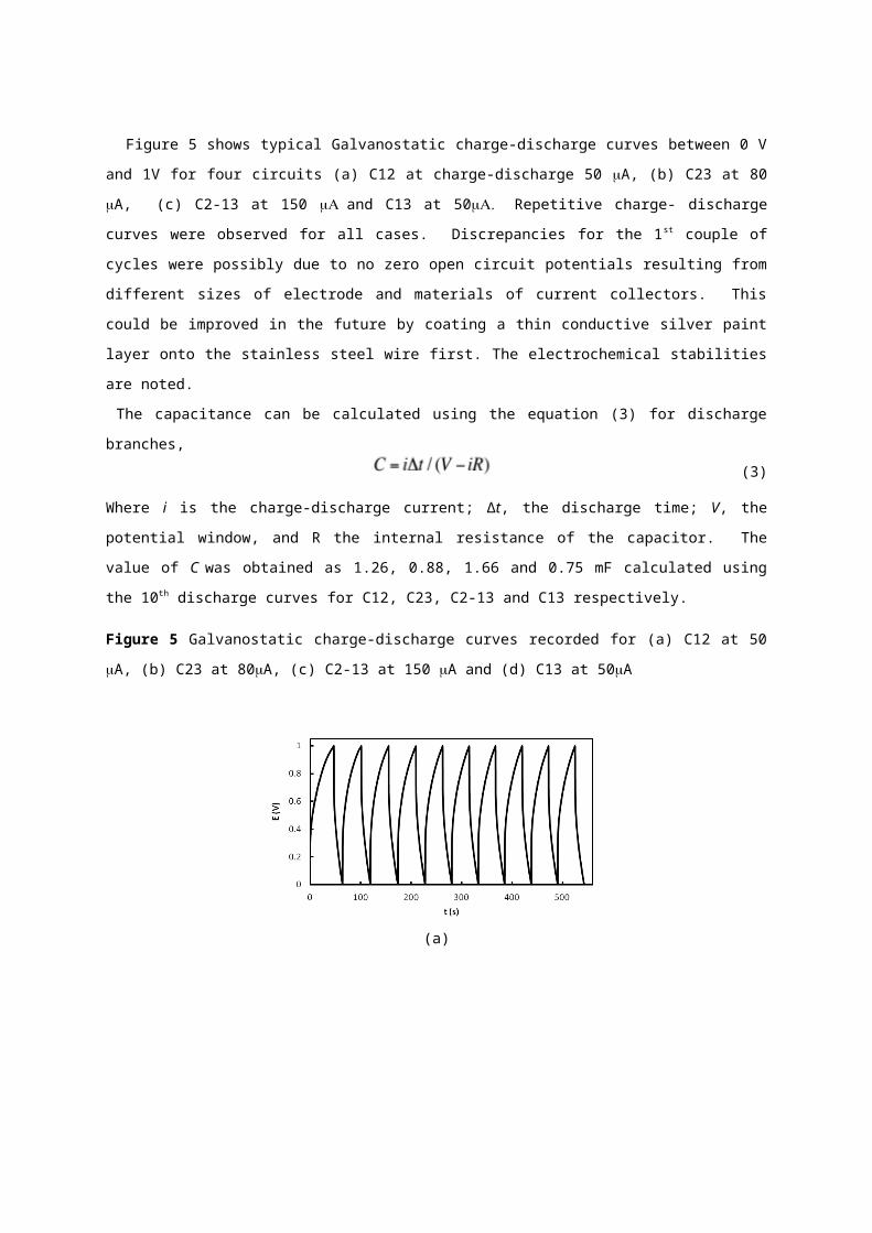
Figure 5 shows typical Galvanostatic charge-discharge curves between 0 V and 1V for four circuits (a) C12 at
charge-discharge 50 A, (b) C23 at 80 A, (c) C2-13 at 150 and C13 at 50 Repetitive charge-
discharge curves were observed for all cases. Discrepancies for the 1st couple of cycles were possibly due to no
zero open circuit potentials resulting from different sizes of electrode and materials of current collectors. This
could be improved in the future by coating a thin conductive silver paint layer onto the stainless steel wire first.
The electrochemical stabilities are noted.
The capacitance can be calculated using the equation (3) for discharge branches,
(3)
Where i is the charge-discharge current; Δt, the discharge time; V, the potential window, and R the internal
resistance of the capacitor. The value of C was obtained as 1.26, 0.88, 1.66 and 0.75 mF calculated using the
10th discharge curves for C12, C23, C2-13 and C13 respectively.
Figure 5 Galvanostatic charge-discharge curves recorded for (a) C12 at 50 A, (b) C23 at 80A, (c) C2-13 at
150 A and (d) C13 at 50A
(a)
(b)
(c)
(d)
To study the fabrication procedure’s robustness and the device’s functionality further, a 16 cm long two
capacitive layers thread supercapacitor was produced. Figure 6 shows cyclic voltammograms at 100 mV/s for
C12, C23, C2-13 and C13 (a) and at different scan rates for C13 between 0 V and 2 V (b). Capacitances were
calculated using equation (1) as 3.2, 1.5, 4.1 and 2.1 mF respectively. Stored energies were calculated as 1.6,
0.75, 2 and 4.2 mJ for C12, C23, C2-13 and C13 respectively, C13 held the highest energy as expected. As
shown in figure 6b, for all scan rates, the device was stable within the 2 V potential window. The capacitance
(4.1, 2.8 and 2.1mF) decreases with increasing scan rate.
Figure 6 Cyclic voltammograms for a 16 cm two-layer thread supercapacitor (a) at 100 mV/s for four different
electrical circuits, and (b) at different scan rates for the C13
(a)
(b)
Conclusions and outlook
We have developed a novel coaxial two capacitive layers supercapacitor with a large potential window and a
high energy storage capacity. Two concentric capacitive layers were coated on a single stainless steel wire using
a newly designed semi-automatic dip coating setup, sequentially. The fabrication procedures are robust, and
have great potential for scale-up. Owing to its coaxial structure, it is compact, has high energy density, and a
wide operating potential window. This device as a flexible energy storage unit is ready to integrate with other
wearable electronics.
Operating as a single integral thread but with a series connection between the two internal capacitors can
provide a driving voltage of 2 volts, sufficient for simple applications like lighting an LED. The multilayer
threads themselves can be further combined in series and parallel to match the power requirement for other
loads. For example, three thread structures in series could be used to drive a 6 volt motor. The flexible thread
combinations have the possibility to eventually be used in wearable applications such as providing 5 volts to
recharge a mobile phone or other wearable electronic devices.
We are aware that there are some limitations with charging and discharging at high scan rates. This could be in
part due to leakage and self-discharge, but we believe this is also due to the poor diffusion of ions to the
electrode surface, as the ions have to move through a viscous medium. If the viscosity were to be reduced, this
might reduce some of the effects seen.
The concept of the device and fabrication procedure are not only applicable to two capacitive layers and carbon-
carbon symmetric configurations but also many capacitive layers and asymmetric supercapacitors. The
electrical properties are easy to tune by varying the number of capacitive layers and the active layers’ thickness,
to satisfy the needs of electronic devices, and these will be explored in the future.
Acknowledgment
This work was funded by the EU FP7 programme.
References
De Rossi, D., Carpi,F., Lorussi,F., Scilingo,E. P., Tognetti,A. and Paradiso,R. (2005), "Electroactive fabrics and wearable man-machine interfaces", Wearable Electronics and Photonics, pp. 59-80.
Salvo, P., Di Francesco,F., Costanzo,D., Ferrari,C., Trivella,M. and De Rossi,D. (2010), "A Wearable Sensor for Measuring Sweat Rate", IEEE SENSORS JOURNAL, Vol. 10 No. 10 pp. 1557-1558.
Shim, B. S., Chen,W., Doty,C., Xu,C. and Kotov,N. A. (2008), "Smart Electronic Yarns and Wearable Fabrics for Human Biomonitoring made by Carbon Nanotube Coating with Polyelectrolytes", Nano Letters, Vol. 8 No. 12 pp. 4151-4157.
Zou, D., Wang,D., Chu,Z., Lv,Z. and Fan,X. (2010), "Fiber-shaped flexible solar cells", Coord Chem Rev, Vol. 254 No. 9 pp. 1169-1178.
Nishide, H. and Oyaizu,K. (2008), "Toward Flexible Batteries", Science, Vol. 319 No. 5864 pp. 737-738.
Kang, Y. J., Chung,H., Han,C. and Kim,W. (2012a), "All-solid-state flexible supercapacitors based on papers coated with carbon nanotubes and ionic-liquid-based gel electrolytes", Nanotechnology, Vol. 23 No. 6 pp. 065401.
Xu, X et al. (2012) Fiber-Based All-Solid-State Flexible Supercapacitors for Self-Powered Systems ACS Nano, 2012, 6 (10), pp 9200–9206
Fu, Y., Cai,X., Wu,H., Lv,Z., Hou,S., Peng,M., et al. (2012), "Fiber supercapacitors utilizing pen ink for flexible/wearable energy storage", Advanced materials (Deerfield Beach, Fla.), Vol. 24 No. 42 pp. 5713.
Meng, C., Gall,O. Z. and Irazoqui,P. P. (2013), "A flexible super-capacitive solid-state power supply for miniature implantable medical devices", Biomed Microdevices, Vol. 15 No. 6 pp. 973-983.
Fu, Y., Wu,H., Ye,S., Cai,X., Yu,X., Hou,S., et al. (2013), "Integrated power fiber for energy conversion and storage", Energy & Environmental Science, Vol. 6 No. 3 pp. 805-812.
Le, V., Kim,H., Ghosh,A., Kim,J., Chang,J., Vu,Q., et al. (2013), "Coaxial Fiber Supercapacitor Using All-Carbon Material Electrodes", ACS NANO, Vol. 7 pp. 5940.
Harrison, D., Qiu,F., Fyson,J., Xu,Y., Evans,P. and Southee,D. (2013), "A coaxial single fibre supercapacitor for energy storage", Physical Chemistry Chemical Physics, Vol. 15 No. 29 pp. 12215-12219.
Zhao,C. and Zheng,W. (2015) “A review for aqueous electrochemical supercapacitors" Frontiers in Energy Research, Vol 3, No. 00023 published 8th May 2015.
Yuan, C., Hou,L., Li,D., Shen,L., Zhang,X. and Zhang,F. (2011), "Synthesis of flexible and porous cobalt hydroxide/conductive cotton textile sheet and its application in electrochemical capacitors", Electrochim Acta, Vol. 56 No. 19 pp. 6683-6687.
Dalton, A., Collins,S., Razal,J., Munoz,E., Ebron,V., Kim,B., et al. (2004), "Continuous carbon nanotube composite fibers: properties, potential applications, and problems", JOURNAL OF MATERIALS CHEMISTRY, Vol. 14 No. 1 pp. 1-3.
Ng, K. C., Zhang,S., Peng,C. and Chen,G. Z. (2009), "Individual and Bipolarly Stacked Asymmetrical Aqueous Supercapacitors of CNTs/SnO(2) and CNTs/MnO(2) Nanocomposites", J Electrochem Soc, Vol. 156 No. 11 pp. A846-A853.
Kang, Y. J., Chung,H., Han,C. and Kim,W. (2012b), "All-solid-state flexible supercapacitors based on papers coated with carbon nanotubes and ionic-liquid-based gel electrolytes", Nanotechnology, Vol. 23 No. 6 pp. 065401.