Embed Size (px)
Citation preview

Energies 2021, 14, 4287. https://doi.org/10.3390/en14144287 www.mdpi.com/journal/energies
Viewpoint
Cyber Security for Multi‐Station Integrated Smart Energy
Stations: Architecture and Solutions
Yangrong Chen, June Li *, Qiuyu Lu, Hai Lin, Yu Xia and Fuyang Li
Key Laboratory of Aerospace Information Security and Trusted Computing, Ministry of Education, School of
Cyber Science and Engineering, Wuhan University, Wuhan 430072, China; [email protected] (Y.C.);
[email protected] (Q.L.); [email protected] (H.L.); [email protected] (Y.X.);
[email protected] (F.L.)
* Correspondence: [email protected]
Abstract: Multi‐station integration is motivated by the requirements of distributed energies inter‐
connection and improvements in the efficiency of energy systems. Due to the diversity of commu‐
nication services and the complexity of data exchanges between in‐of‐station and out‐of‐station,
multi‐station integrated systems have high security requirements. However, issues related to cyber
security for multi‐station integrated systems are seldom explored. Hence, this paper designs the
secondary system architecture and proposes cyber security protection solutions for smart energy
stations (SESt) that integrate the substation, photovoltaic station, energy storage station, electric ve‐
hicle charging station, and data center station. Firstly, the composition of SESt and functions of each
substation are presented, a layered architecture of SESt is designed, and data exchanges of SESt are
analyzed. Then, the cyber security threats and requirements of SESt are illustrated. Moreover, the
cyber security protection principle and a cyber security protection system for SESt are proposed. On
this basis, a security zoning and isolation scheme for SESt is designed. Finally, a traffic isolation
scheme based on virtual local area networks (VLANs), a real‐time guarantee scheme for communi‐
cations based on service priority, and an enhancing cyber security scheme based on improved IEC
62351 are proposed for SESt.
Keywords: multi‐station integration; cyber security; security zoning; service priority; queue sched‐
uling; improved IEC 62351
1. Introduction
The concept of smart energy was first proposed by IBM in 2009, and “smart energy”
was regarded as an important part of the “smart planet” strategy [1]. In the same year,
Chinese scholars pointed out that a smart energy system needs to be developed with a
smart grid as the core. Thus, a series of energy source problems, which affect sustainable
development, would be fundamentally solved [2]. The so‐called “smart energy” refers to
establishing an information‐based new energy system. The new energy system, which
integrates production, storage, transmission, conversion, and utilization of various en‐
ergy sources, can help to achieve an optimal balance between energy resources, energy
conversion, and energy demand. Then, the utilization efficiency of energy resources and
equipment, and the economic benefits of energy investment, will be improved. Further‐
more, the overall benefits of social and economic development will be promoted.
In 2019, China State Grid Co., Ltd. proposed a new pattern that uses substation re‐
sources to build and operate charging stations, energy storage stations, and data center
stations. Since then, the concept of multi‐station integration has been formally proposed,
with the goals of achieving resource sharing, optimizing urban resource allocation, im‐
proving system status awareness and data analysis computing efficiency, and realizing
local consumption of renewable energy. Multi‐station integration lays the foundation for
Citation: Chen, Y.; Li, J.; Lu, Q.; Lin,
H.; Xia, Y.; Li, F. Cyber Security for
Multi‐Station Integrated Smart
Energy Stations: Architecture and
Solutions. Energies 2021, 14, 4287.
https://doi.org/10.3390/en14144287
Academic Editor: Ali Mehrizi‐Sani
Received: 11 June 2021
Accepted: 14 July 2021
Published: 15 July 2021
Publisher’s Note: MDPI stays neu‐
tral with regard to jurisdictional
claims in published maps and institu‐
tional affiliations.
Copyright: © 2021 by the authors. Li‐
censee MDPI, Basel, Switzerland.
This article is an open access article
distributed under the terms and con‐
ditions of the Creative Commons At‐
tribution (CC BY) license (http://crea‐
tivecommons.org/licenses/by/4.0/).

Energies 2021, 14, 4287 2 of 21
constructing an energy internet with comprehensive situation awareness, efficient infor‐
mation processing, and convenient and flexible application [3,4].
With the information development of the power grid, multi‐station integration be‐
comes an inevitable trend. Therefore, multi‐station integration has gradually become a
hot spot and innovative research direction for academia and industry.
1.1. Motivation
Multi‐station integration refers to the fusion construction of the data center station,
charging station, energy storage station, 5G base station, BeiDou base station, and photo‐
voltaic station based on existing substations. Multi‐station integration can support smart
grid services internally, cultivate the electric Internet of Things (eIoT) market externally,
and promote the construction of energy internet. The multi‐station integrated system pos‐
sesses the capabilities of open sharing and deep collaboration, and brings a boost for con‐
structing a safe and efficient energy system. However, it also brings a lot of information
sharing and security problems, such as the problem of security zoning and isolation be‐
tween substations, the problem of safe information sharing between sub‐systems with dif‐
ferent security requirements, and the problem of what kind of security protection
measures need to be taken for each sub‐system [5–7]. Therefore, how to ensure the cyber
security of the multi‐station integrated system is an urgent problem.
At present, researchers are mainly studying how to improve energy efficiency in a
multi‐station integrated system, while few studies have focused on cyber security for
multi‐station integrated systems. To our knowledge, this work is the first survey discuss‐
ing cyber security of multi‐station integrated systems.
In existing research on multi‐station integrated systems, most research has focused
on application scenarios, architecture design, planning and investment construction, and
cyber security of a single energy station connected to the power grid. Harnett et al. [8]
analyzed the cyber security threats that electric vehicle charging stations face for the first
time. Sebastian et al. [9] summarized current studies about cyber security risks in IoT‐
based distributed energy resource devices and proposed guidelines for mitigating these
risks. Saleem et al. [10] systematically reviewed the existing architectures, application sce‐
narios, and prototypes of IoT‐aided smart grid systems, and highlighted the problems,
challenges, and future research directions for IoT‐aided smart grid systems. Zhu et al. [11]
constructed a regional integrated energy system model based on key equipment and con‐
ventional equipment by analyzing the structure of regional integrated energy systems.
Wang et al. [12] analyzed the independent operation mode of each substation in multi‐
station integration and discussed the feasibility of multi‐station integrated operation
mode based on the actual project background. To optimize the investment construction
and planning of multi‐station integration, Zhang et al. [13] proposed a comprehensive
index system for the safety and benefit evaluation of multi‐station integrated systems. Li
et al. [14] built a protection framework of cyber security for electric vehicle charging sta‐
tions based on the security threat analysis of the communication network in [15]. Wang
[16] introduced the security protection and reinforcement measures of regional schedul‐
ing SCADA/EMS. Zou et al. [17] proposed a model of network security defense system
for smart substations by analyzing the network security threats and protection demand
of smart substation.
From the above reviews, it can be seen that there are few works about cyber security
for multi‐station integrated systems. Although these studies have laid the foundation for
further study of multi‐station fusion technologies, there are some shortcomings as follows.
(1) Only the cyber security of a single energy station connected to the power grid has
been studied.
(2) The present studies mainly focused on the application scenarios, architecture de‐
sign, planning and investment construction of multi‐station integration. However, there
is little research on cyber security for multi‐station integration.

Energies 2021, 14, 4287 3 of 21
(3) The existing protection system or solutions are for a single energy station con‐
nected to the power grid, but are not suitable for multi‐station integrated systems.
In conclusion, it is difficult to effectively reveal complex data exchanges of the multi‐
station integrated system based on existing research. Furthermore, it is more difficult to
deal with the potential security threats in cyberspace.
To enhance the cyber security protection level of the multi‐station integrated system,
this paper studies cyber security and solutions for multi‐station integrated smart energy
station (SESt).
1.2. Contribution
The main contributions of this paper are summarized as follows:
(1) The information service system of a five‐station integrated SESt is designed. SESt
integrates the substation, photovoltaic station, energy storage station, electric vehicle
charging station (hereinafter, charging station), and data center station. SESt can promote
service integration and improve the overall utilization rate of resources.
(2) A SESt’s layered architecture is designed. This architecture has five layers of the
physical device layer, communication platform layer, process monitoring layer (hereinaf‐
ter, process layer), and system application layer. Moreover, the data exchanges of SESt are
fully analyzed. Based on the analysis, the cyber security threats and requirements of each
substation in SESt are illustrated, which can help to determine proper protection counter‐
measures.
(3) The cyber security protection principle and a protection system are proposed for
SESt. The protection principle refers to “security zoning, enhanced borders; dedicated net‐
work, multi‐layer protection; horizontal isolation, vertical authentication; classified stor‐
age, controlled sharing”. The protection system design takes the current technical level
and realizability into consideration and covers cyber security solutions for each layer. On
this basis, a security zoning and isolation scheme is designed for SESt. This scheme can
ensure the confidentiality and integrity of information, and protect SESt against illegal
access. Thus, the security risk of SESt will be reduced.
(4) Security reinforcement solutions for SESt are proposed. The solutions involve a
traffic isolation scheme based on VLAN, a real‐time guarantee scheme for communica‐
tions based on service priorities, and an enhancing scheme for cyber security based on
improved IEC 62351. These solutions can further isolate malicious traffic, guarantee the
real‐time and reliable transmission of real‐time services under flood attacks, resist repu‐
diation, and prevent key messages in SESt from being stolen and tampered with.
1.3. Organization
The remainder of the paper is organized as follows. In Section 2, the composition of
SESt is presented, the information service system and layered architecture of SESt are de‐
signed, and the data exchanges of SESt are analyzed. In Section 3, the cyber security
threats and requirements of SESt are analyzed. In Section 4, the cyber security protection
principle and protection system are proposed. In Section 5, the security zoning and isola‐
tion scheme is designed for SESt. In Section 6, three security reinforcement solutions for
SESt are presented. In Section 7, the security analysis of the proposed cyber security pro‐
tection solutions is given. Finally, the paper is concluded in Section 8.
2. System Architecture and Data Exchanges
2.1. System Architecture
The five‐station integrated SESt designed in this paper includes substation, photo‐
voltaic station, energy storage station, charging station, and data center station. The con‐
struction goal of SESt is to rely on the substation for realizing resource integration and
sharing, promoting friendly interaction between the five stations, so that the “third‐rate
one” of energy flows, data and service flows will be achieved. To analyze the composition,

Energies 2021, 14, 4287 4 of 21
information service system, and data exchanges of the designed SESt, the functions of each
substation are first analyzed as follows.
The substation, which undertakes the tasks of power generation, transmission, and
distribution, is the core of SESt. Relying on substations to construct SESt can help enter‐
prises expand from the traditional power supply service to the comprehensive energy
service [18]. At the same time, SESt can promote friendly interaction and mutual benefit
for power suppliers, equipment providers, and users.
The photovoltaic station can supply power for the operation, lighting, and cooling of
SESt. Thus, the power and cost loss caused by the independent operation of the substation
will be reduced.
The energy storage station has the function of peak‐cutting and valley filling [19].
That is to say, it stores power when the power grid has excess power and supplies power
when the power grid has insufficient power. Thus, the complementary coordination and
optimal control of energy can be achieved. In addition, the energy storage station can help
energy storage service providers to acquire economic benefits through participating in
power auxiliary market transactions.
The charging station provides electric vehicle charging and rental services, expands
the charging service market, and increases user stickiness. Meanwhile, the charging sta‐
tion increases SESt’s reasonable income by charging service and parking fees.
The data center station mainly provides services for grid enterprises. Internally, the
data center station mainly collects and processes electricity information. That is to say,
this substation provides real‐time calculation and data services for SESt. Thus, the nearby
storage, analysis, and utilization of power data will be realized. The internal services lay
a solid foundation for the extended service of power data value. Externally, the data center
station mainly provides cloud computing services and information infrastructure ser‐
vices. For example, this substation can provide network communication, computing stor‐
age, and disaster recovery for different enterprises. Hence, both internal and external serv‐
ers need to be equipped to the data center station.
To realize information and function sharing, we build a multi‐services sharing trans‐
mission network at the station level for substation, energy storage station, photovoltaic
station, and charging station. The service flows share switch (i.e., network communication
equipment) resources. Moreover, we suggest designing an integrated monitoring system
and integrated auxiliary control system for the whole station. The corresponding service
systems need to be deployed at the control center for unified management. Based on the
above analysis, the composition of the SESt we design is illustrated in Figure 1.
Figure 1. Composition of SESt.
In Figure 1, the integrated monitoring system at the control center is composed of
five sub‐systems: substation automation system, photovoltaic monitoring system, energy
storage station monitoring system, charging monitoring system, and integrated power
supply monitoring system. The integrated auxiliary control system at the control center is
Smart energy station
Process monitoring of photovoltaic station
Energy storage battery
Energy storage station
Battery management
system
Energy storage bidirectional converter
Anti‐island
protection
Photovoltaic module
Photovoltaic station
Charging pile
Electric vehicle charging station
Charging management
Substation equipment
Substation
Process monitoring of substation
Step‐up transformer protection
Electrical lines
Equipment condition monitoring
Monitoring of charging
pile
DC/DC converter
Control center
Fault recorder system
Integrated monitoring system Integrated auxiliary control system
Electric energy metering system
Power quality monitoring system
Network security
monitoring system
Unified time synchronization
system for the whole station
Power conversion system
Servers for enterprise internal business in data
center
Nearby storage and analysis of production data
Information infrastructure
services
Cloud computing services
Servers for enterprise external business in data
center
Edge computing

Energies 2021, 14, 4287 5 of 21
composed of the equipment condition monitoring system, video monitoring system, en‐
vironmental monitoring system, fire alarm system, and lighting system. Based on SESt’s
composition in Figure 1 and the above analysis for SESt’s operation control requirements,
we design the information service system of SESt, as illustrated in Figure 2.
Figure 2. Information service systems of SESt.
Based on the function of each substation, SESt’s composition in Figure 1 and infor‐
mation service system of SESt in Figure 2, we design the layered architecture of SESt, as
illustrated in Figure 3. The layered architecture has four layers, i.e., the physical device
layer, the communication platform layer, the process layer, and the system application
layer.
Figure 3. Layered architecture of SESt.
In Figure 3, the physical device layer includes the primary power equipment and
electrical lines. The communication platform layer includes communication links and
equipment (e.g., switches, routers, and communication gateways). This layer provides
communication services and interface for SESt. The process layer includes the measure‐
ment and control devices. This layer is responsible for monitoring the equipment condi‐
tion of the physical device layer, uploading measurement information, and receiving con‐
trol instructions issued by the upper‐level station control host. The system application
layer, which involves real‐time and non‐real‐time control services, includes all the systems
in Figure 2.
2.2. Data Exchanges
All kinds of data need to be collected and transmitted in SESt. By analyzing the data
exchanges of SESt, the communication services in SESt can be obtained. The data exchange
analysis can lay a foundation for the subsequent cyber security threats and requirements
analysis. The data that need to be collected and transmitted in SESt are as follows.
Integrated monitoring system
Energy storage station
monitoring system
Charging station monitoring system
Photovoltaic monitoring system
Integrated auxiliary control systemElectric energy
metering system
Fault recorder system
Video su
rveillan
ce syste
m
Enviro
nmental
monito
ring sy
stem
Fire alarm
system
Fire p
ump
monito
ring sy
stem
Heatin
g an
d
ventilatio
n
monito
ring sy
stem
Lightin
g mon
itorin
g syste
m
Network security
monitoring system
Power quality
monitoring system
Substation automation monitoring system
Integrated power supply
monitoring system
Unified time synchronization
system for the whole station
Microgrid automation system
Integrated energy coordinated
control system
Equipmen
t conditio
n
monito
ring sy
stem
Photovoltaic array module
Energy storage battery
Photovoltaic inverter
Energy storage bidirectional converter
Equipment conditon monitoring
Process monitoring of photovoltaic
station
Charging pile
Step‐up transformer protection
System lines
Process monitoring of substation
System application layer Unified time
synchronization system
Integrated auxiliary control
system
Network security monitoring system
Power quality monitoring system
Electric energy metering system
Substation equipment
Fault recorder system
Process monitoring layer
physical device layer
Anti‐island protection
Power conversion system
Battery management system
Charging management
Monitoring of charging pile
Integrated monitoring system
Communication gateways
Communication lines
SwitchesCommunication platform layer
Routers

Energies 2021, 14, 4287 6 of 21
The substation has the following data exchanges. (1) Telemetry data (e.g., bus voltage
and current) and remote communication data (e.g., breaker positions and protection sig‐
nals) need to be sent to the integrated monitoring system through the station‐level net‐
work. Then, these data need to be sent to the dispatch center via the power dispatch data
network. (2) Various control instructions issued by the integrated monitoring system need
to be sent to the substation via the station‐level network. In addition, the control instruc‐
tions issued by the dispatch center need to be sent to the substation via the power dis‐
patching data network. (3) The primary equipment condition in the substation needs to
be sent to the independent equipment condition monitoring system via the station‐level
network.
The photovoltaic station and energy storage station have the following data ex‐
changes. (1) The process layer needs to collect the measurement information. Then, the
collected data need to be sent to the integrated monitoring system through the station‐
level network. (2) The control instructions issued by the integrated monitoring system
need to be sent to the two stations, respectively, through the station‐level network.
The charging station has the following data exchanges. (1) The process layer needs to
collect real‐time information (e.g., running state, measurement information, protection ac‐
tions, and alarms) of the charging pile power supply system and send it to the integrated
monitoring system via the station‐level network. (2) Various control instructions (e.g.,
opening and closing of circuit breakers, starting and stopping of charging piles, and mod‐
ification of setting values) issued by the integrated monitoring system need to be sent to
the charging station via the station‐level network.
The data center station provides both internal and external services for grid enter‐
prises. The internal and external services are completely independent. Hence, the data
exchanges related to the data center station are as follows. (1) The internal production data
need to be sent to the integrated power data network. These data also need to be stored at
the external server of the data center station and used for big data analysis. (2) The data
on external servers need to be sent to other data center stations through the dedicated
power communication network, or to the internet through firewalls for query and use by
social users.
In addition, SESt also includes the following data exchanges.
(1) The fault recorders need to record the changes in power parameters caused by large
disturbances. These parameters need to be sent to the fault recorder system through
the station‐level network. Then, the fault recorder system analyzes the parameters
and sends them to the relay protection and fault information management system
via the power dispatch data network.
(2) The power quality monitors need to collect power parameters (e.g., the voltage on
high and low voltage side of the main transformer, current, and load), which are an‐
alyzed and calculated by the power quality monitoring system to obtain power qual‐
ity data. Then the data need to be sent to the integrated application server, then to
the provincial electric power research institute (PEPRI) through the integrated power
data network.
(3) Smart meters need to collect the power consumption data and send the data to the
electric energy metering system via the RS485 bus. Then, the processed data need to
be sent to the electricity information collection system and the main station of meter‐
ing, respectively.
(4) The network security monitors need to collect the security events of the servers,
workstations, network equipment, and security protection equipment in the commu‐
nication network. Then, the network security monitoring system analyzes these se‐
curity events and sends the analysis results to PEPRI through the power dispatching
data network.
(5) Other auxiliary control devices need to collect environmental data. These data need
to be sent to the integrated auxiliary control system through the station‐level net‐
work, then to PEPRI through the integrated power data network.

Energies 2021, 14, 4287 7 of 21
(6) The time synchronization data of the unified time synchronization system for the
SESt need to be sent to the secondary equipment and other substations through the
station‐level network.
Based on the above analysis, the data exchanges of SESt are illustrated in Figure 4.
Figure 4. Data Exchanges of SESt.
Information corresponding to each number in Figure 4 is illustrated in Appendix A
Table A1.
In conclusion, compared with a single substation, SESt has more communication ser‐
vice types, more complex data exchanges, and wider exposure. Thus, SESt is more vul‐
nerable to cyber attacks.
3. Cyber Security Threats and Requirements
The cyber security threats that SESt faces and their impact on the power grid deter‐
mine what security protection measures to be taken. Hence, this section starts with the
analysis of the cyber security threats of SESt for determining its security requirements.
The main security objectives are confidentiality, integrity, availability, authenticity,
and non‐repudiation. Therefore, based on the SESt’s system architecture in Figure 3 and
data exchanges analyzed in the previous section, this section analyzes the cyber security
threats that SESt faces and its security requirements from the following five aspects: de‐
stroying the availability of the system, destroying the integrity of data, destroying the
confidentiality of information, forging user identities, and denial of behavior. For SESt,
the function, communication network technologies, and the exposure degree of each sub‐
station are different. Thus, the cyber security threats that each substation faces and the
impact of these threats on SESt are also different. This section divides the five substations
into the following three categories to analyze: (1) the substation, photovoltaic station, and
energy storage station; (2) the charging station; (3) the data center stations.
(1) Cyber security threats and requirements of the substation, photovoltaic station, and
energy storage station
Integrated monitoring system
Charging stationEnergy storage
stationPhotovoltaic station Substation
Equipment conditon monitoring system
Intelligent auxiliary monitoring system
Electric energy metering system
Network security
monitoring system
Power quality
monitoring system
25
Provincial dispatch center
Main station of metering
SCADAsystem
Electricity information collection system
Provincial electric power research institute
Integrated power data network
Relay protection and fault information
management system
Fault recorder system
Power dispatch data network
Integrated auxiliary control system
Unified time synchronization
system
Servers for enterprise
internal business
28Servers for
enterprise external business
30
Internet
Private communication
network
32
Data center station

Energies 2021, 14, 4287 8 of 21
In SESt, the substation, photovoltaic station, and energy storage station mainly in‐
volve production control services. There are no special external data exchange require‐
ments. Therefore, the cyber security threats and requirements of the three substations are
the same.
The data exchanged between the three substations and other service systems mainly
include control instructions, equipment condition, and power quality data (e.g., voltage, current, and system frequency). The data are encapsulated into a communication packet
for transmission in the communication network of SESt. On this basis, the main cyber
security threats of the three substations are as follows.
Attackers eavesdrop on these data directly or indirectly on the network for future
attacks. In the process of eavesdropping, attackers can obtain valuable information
by analyzing network communication protocol without affecting the normal opera‐
tion of SESt.
Attackers control a target device by tampering with, forging, or replaying control
messages, thereby causing the mis‐operation of the target device or the instability of
SESt.
Attackers send a mass of data packets to the target host, causing resource consump‐
tion and the host to crash. In addition, the three substations also face various kinds
of attacks such as malicious code attacks, buffer overflow attacks, repudiation at‐
tacks, application layer injection attacks and so on.
Hence, the security requirements of the three substations mainly include confidenti‐
ality, integrity, availability, authenticity, and non‐repudiation. It should be noted that en‐
suring the cyber security of the substation is more important than the other two stations
from the perspective of the safe and stable operation of SESt. Hence, this factor needs to
be considered when designing security protection countermeasures.
(2) Cyber security threats and requirements of the charging station
The charging station is different from other substations. Charging piles need to be
open and exchange data with users. The communication data include production infor‐
mation and users’ information. Since the charging piles are located outside, users can di‐
rectly touch the data acquisition and control devices equipped to the charging piles. On
this basis, the main cyber security threats of the charging station are as follows.
Attackers probe the charging station board to eavesdrop on inter‐component com‐
munications and gain any valuable information (e.g., the user password and the in‐
formation of users ID card).
Attackers impersonate valid end‐users and cheat network access control systems.
Then, the attackers can perform any operation.
Attackers flood information to the charging station, which would exceed the pro‐
cessing ability of the charging station. Hence, ordinary users’ access will be ham‐
pered. In addition, various software modules in the charging station may be ex‐
ploited to launch more sophisticated attacks (e.g., install malware).
Hence, the security requirements of the charging station mainly include confidenti‐
ality, availability, authenticity, and non‐repudiation, as well as the security isolation with
other substations.
(3) Cyber security threats and requirements of the data center station
The internal and external servers are the key part of the data center station. The in‐
ternal servers process and analyze enterprise internal data related to production manage‐
ment. The external servers connected to internet process and analyze management infor‐
mation data. On this basis, the main cyber security threats of the data center station are as
follows.
Attackers eavesdrop on the communication network for future attacks.
Energies 2021, 14, 4287 9 of 21
The external servers face the same security threats as traditional networks, such as
DoS attacks, tampering attacks, forgery attacks, eavesdropping, and deception at‐
tacks.
Hence, the security requirements of the data center station mainly include confiden‐
tiality and availability.
In addition, the data center station needs to store data for a long time. Once the data
are lost, great economic loss and social impact will occur. Therefore, the data center station
needs to have the function of off‐site disaster recovery, which can ensure data recovery in
time after being lost due to malicious attacks or natural disasters.
The threats and security requirements of the electric energy metering system, power
quality monitoring system, equipment condition monitoring system, and fault recorder
system are consistent with the conventional power system [20], so we do not repeat them
in this paper.
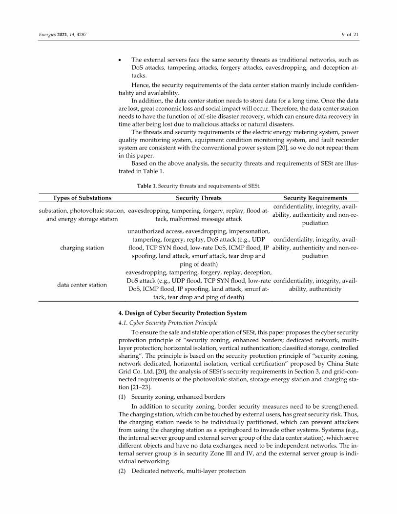
Based on the above analysis, the security threats and requirements of SESt are illus‐
trated in Table 1.
Table 1. Security threats and requirements of SESt.
Types of Substations Security Threats Security Requirements
substation, photovoltaic station,
and energy storage station
eavesdropping, tampering, forgery, replay, flood at‐
tack, malformed message attack
confidentiality, integrity, avail‐
ability, authenticity and non‐re‐
pudiation
charging station
unauthorized access, eavesdropping, impersonation,
tampering, forgery, replay, DoS attack (e.g., UDP
flood, TCP SYN flood, low‐rate DoS, ICMP flood, IP
spoofing, land attack, smurf attack, tear drop and
ping of death)
confidentiality, integrity, avail‐
ability, authenticity and non‐re‐
pudiation
data center station
eavesdropping, tampering, forgery, replay, deception,
DoS attack (e.g., UDP flood, TCP SYN flood, low‐rate
DoS, ICMP flood, IP spoofing, land attack, smurf at‐
tack, tear drop and ping of death)
confidentiality, integrity, avail‐
ability, authenticity
4. Design of Cyber Security Protection System
4.1. Cyber Security Protection Principle
To ensure the safe and stable operation of SESt, this paper proposes the cyber security
protection principle of “security zoning, enhanced borders; dedicated network, multi‐
layer protection; horizontal isolation, vertical authentication; classified storage, controlled
sharing”. The principle is based on the security protection principle of “security zoning,
network dedicated, horizontal isolation, vertical certification” proposed by China State
Grid Co. Ltd. [20], the analysis of SESt’s security requirements in Section 3, and grid‐con‐
nected requirements of the photovoltaic station, storage energy station and charging sta‐
tion [21–23].
(1) Security zoning, enhanced borders
In addition to security zoning, border security measures need to be strengthened.
The charging station, which can be touched by external users, has great security risk. Thus,
the charging station needs to be individually partitioned, which can prevent attackers
from using the charging station as a springboard to invade other systems. Systems (e.g.,
the internal server group and external server group of the data center station), which serve
different objects and have no data exchanges, need to be independent networks. The in‐
ternal server group is in security Zone III and IV, and the external server group is indi‐
vidual networking.
(2) Dedicated network, multi‐layer protection
Energies 2021, 14, 4287 10 of 21
The external server group of the data center station undertakes social services, and it
is an independent service system using a dedicated fiber channel for communication. In
other security zones, multiple virtual private networks (VPNs) need to be configured.
Thus, the vertical interconnection in each security zone is only carried out in the same
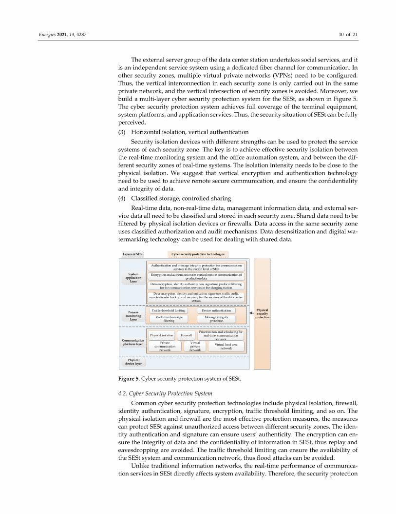
private network, and the vertical intersection of security zones is avoided. Moreover, we
build a multi‐layer cyber security protection system for the SESt, as shown in Figure 5.
The cyber security protection system achieves full coverage of the terminal equipment,
system platforms, and application services. Thus, the security situation of SESt can be fully
perceived.
(3) Horizontal isolation, vertical authentication
Security isolation devices with different strengths can be used to protect the service
systems of each security zone. The key is to achieve effective security isolation between
the real‐time monitoring system and the office automation system, and between the dif‐
ferent security zones of real‐time systems. The isolation intensity needs to be close to the
physical isolation. We suggest that vertical encryption and authentication technology
need to be used to achieve remote secure communication, and ensure the confidentiality
and integrity of data.
(4) Classified storage, controlled sharing
Real‐time data, non‐real‐time data, management information data, and external ser‐
vice data all need to be classified and stored in each security zone. Shared data need to be
filtered by physical isolation devices or firewalls. Data access in the same security zone
uses classified authorization and audit mechanisms. Data desensitization and digital wa‐
termarking technology can be used for dealing with shared data.
Figure 5. Cyber security protection system of SESt.
4.2. Cyber Security Protection System
Common cyber security protection technologies include physical isolation, firewall,
identity authentication, signature, encryption, traffic threshold limiting, and so on. The
physical isolation and firewall are the most effective protection measures, the measures
can protect SESt against unauthorized access between different security zones. The iden‐
tity authentication and signature can ensure users’ authenticity. The encryption can en‐
sure the integrity of data and the confidentiality of information in SESt, thus replay and
eavesdropping are avoided. The traffic threshold limiting can ensure the availability of
the SESt system and communication network, thus flood attacks can be avoided.
Unlike traditional information networks, the real‐time performance of communica‐
tion services in SESt directly affects system availability. Therefore, the security protection
Physical security protection
System application layer
Process monitoring layer
Physical device layer
Physical isolation Firewall
Encryption and authentication for vertical remote communication of production data
Communication platform layer Virtual local area
network
Virtual private network
Prioritization and scheduling for real‐time communication
services
Data encryption, identity authentication, signature, protocol filtering for the communication services in the charging station
Authentication and message integrity protection for communication services in the station level of SESt
Cyber security protection technologiesLayers of SESt
Data encryption, identity authentication, signature, traffic audit, remote disaster backup and recovery for the services of the data center
station
Traffic threshold limiting
Malformed message filtering
Device authentication
Message integrity protection
Private communication
network

Energies 2021, 14, 4287 11 of 21
system includes the virtual local area network (VLAN) isolation, priority refining of com‐
munication services and its queue scheduling method, authentication and message integ‐
rity protection for communication services, in addition to the common security technolo‐
gies.
In addition, physical security protection measures (i.e., various hardware facilities)
need to be used for preventing unauthorized personnel from physically touching or de‐
stroying SESt’s equipment.
Based on the above security technologies, SESt’s cyber security requirements in Sec‐
tion 3, and the cyber security protection principle in Section 4.1, we propose SESt’s cyber
security protection system, as seen in Figure 5, considering the current technical level and
realizability. This protection system involves the cyber security solutions for the commu‐
nication platform layer, process layer, and system application layer, corresponding to the
layers of Figure 3.
In Figure 5, there is much existing security protection research that can be referenced
for the charging station and data center station. Meanwhile, vertical encryption and au‐
thentication, physical isolation, and firewalls have mature products. Therefore, this paper
focuses on the security zoning and isolation measures, the VLAN division scheme, the
real‐time services prioritization and queue scheduling method, and the security protec‐
tion measures for communication service within the station layer and process layer. These
are the focus of research in the remainder of the paper.
5. Security Zoning and Isolation Scheme
Based on the above sections, the security zoning and isolation scheme for SESt is de‐
signed as Figure 6.
Figure 6. Security zoning and isolation of SESt.
From Figure 6, the real‐time monitoring systems closely related to production are
deployed in Zone I (i.e., the substation automation monitoring system, photovoltaic mon‐
itoring system, energy storage station monitoring system, charging station monitoring
system, etc.). The integrated monitoring system uniformly manages these real‐time sys‐
tems. Non‐real‐time monitoring systems related to production in SESt are deployed in
Zone II (i.e., the integrated auxiliary control system, power quality monitoring system,
electric energy metering systems, equipment condition monitoring system, network secu‐
rity monitoring systems, fault recorder systems, etc.). A firewall is deployed to isolate
Zone I and Zone II. Between SESt and the dispatch center, a vertical encryption authenti‐
cation device is adopted for encrypted transmission. Because the charging station places
outside, social users can touch the charging pile and its electric energy meter. This
Unified time synchronizatio
n system
Integrated monitoring system
Network printer
Network security
monitoring device
Integrated auxiliary control
system1) Equipment
status monitoring system
2) Intelligent auxiliary control
system
Integrated application
server
Electric energy metering
Services in zone
IV
Independent network
Servers for enterprise external business
ZoneⅠ ZoneⅡ
Independent zone
Servers for enterprise internal business
Process monitoring
Equipment condition monitoring device
Substation
Power dispatch data network
Forward isolator Reverse isolator
Vertical encryption device
Vertical encryption device
Reverse isolator
FirewallFirewall
Gateway
Firewall
Integrated power data network
Zone Ⅲ Zone Ⅳ
Other main station systems
Private communication
network
Provincial/prefecture‐level dispatch center
Process monitoring
Battery management system
Process monitoring
Energy storage station
Charging management
Charging pile monitoring
Photovoltaic station
Electric energy meter
Power quality monitoring device
Fault recorder device
Power quality monitoring
device
Electric energy meter
Power quality monitoring device
Electric energy meterElectric energy
meter
Power quality monitoring device
Nearby storage and analysis of production data
Reverse isolator
Charging station
Fault recorder device Fault recorder device
Data center stationPower quality monitoring
deviceElectric energy
meter
Integrated energy
coordinated control system
Integrated power supply
monitoring system
Microgrid automation system
Substation automation system
Internet
Firewall
Firewall
Forward isolator

Energies 2021, 14, 4287 12 of 21
situation will cause unpredictable consequences. Hence, the charging station is zoned in‐
dependently.
In SESt, the charging station needs to communicate with Zone I and Zone II. The
communication information includes measurement information, control instructions, and
metering information. To ensure the security of other systems in SESt, physical isolators
are deployed between the charging station network and other zones, as illustrated in Fig‐
ure 7. Forward and reverse isolators are deployed between the charging station protocol
converter and Zone I. The measurement information is uploaded to the integrated moni‐
toring system through the reverse isolator, and the control instructions issued by the in‐
tegrated monitoring system are sent to the corresponding primary equipment of the
charging station through the forward isolator. The reverse isolator is deployed between
the charging station protocol converter and Zone II. The metering information of the
charging station is sent to the electric energy metering system and the integrated applica‐
tion server. When deploying, the protocol converter, forward isolator, and reverse isolator
can be placed indoors. Meanwhile, since the isolators do not support decryption, no en‐
cryption measures are required between the protocol converter and the isolators. If you
take encryption measures, you need to add a decryption device.
Figure 7. Isolation scheme between the charging station and other systems.
The internal servers of the data center station are deployed in Zone III and Zone IV.
The network of Zone III is connected to the integrated application server in Zone II
through the forward and reverse isolators. Thus, the nearby storage and analysis of pro‐
duction data are achieved, and the production data are sent to the relevant main station
systems through the integrated power data network. The external servers of the data cen‐
ter station are independently zoned, and there are no physical or logical connections be‐
tween the external servers and other zones in SESt. According to the specific situation of
the data center station, two outlets are configured in the network of external servers. One
outlet connects to the power communication network for making full use of the commu‐
nication resources of the power grid enterprises. Thus, rapid communication between dif‐
ferent data center stations is realized, and a large information service network forms. An‐
other outlet connects to the internet through a firewall for providing social users with a
fast local access channel, which can enhance users’ service experience.
According to the stipulations of “General plan for the security protection of the sec‐
ondary power system” and “Regulations on the security protection of electric power mon‐
itoring system”, we deploy special horizontal one‐way security isolation devices between
the production control zone and the management information zone. These devices are
tested and certified by the nationally designated department. The isolation strength is
close to physical isolation. Meanwhile, we deploy domestic hardware firewalls, devices
with access control functions, or equivalent functional facilities between Zone I and Zone

Energies 2021, 14, 4287 13 of 21
II for logical isolation. At the vertical connection between the production control zone and
the wide area network, we use the power‐specific vertical encryption authentication de‐
vice, encryption authentication gateway, and equivalent functional devices tested and cer‐
tified by the nationally designated department. Thus, two‐way identity authentication,
data encryption, and access control will be achieved. The selection scheme for isolation
devices between different zones in Figure 6 is illustrated in Table 2.
Table 2. Selection for isolation devices.
Direction of Data Exchanges Selection Basis of Isolation Device Type of Isolation Device
A/B network switch in Zone I ↔ A/B network
switch in Zone II
between the production control zone and
the production non‐control zone industrial Firewall
integrated application server in Zone II → Data communication gateway in Zone III/IV
from production control zone to manage‐
ment information zone forward isolator
Data communication gateway in Zone III/IV
→ integrated application server in Zone II from management information zone to
production control zone reverse isolator
A/B network switch in Zone I → charging sta‐tion
from production control zone to inde‐
pendent zone forward isolator
charging station (Except electricity meters) → A/B network switch in Zone I
from independent zone to production
control zone reverse isolator
charging station (i.e., electricity meters) → A/B network switch in Zone II
from independent zone to production
control zone reverse isolator
data communication gateway in Zone I ↔ Power dispatching data network
from production control zone to the wide
area network vertical encryption device
data communication gateway in Zone II ↔ power dispatching data network
from production non‐control zone to the
wide area network vertical encryption device
6. Security Reinforcement Solutions
Compared with traditional substations, SESt has wide control surfaces, complex sys‐
tems, and strong interactions between sub‐systems. It is more likely to suffer cyber attacks.
To resist cyber attacks, it is necessary to further strengthen cyber security protection based
on the secure zoning and isolation scheme.
As far as we know, IEC 61,850 communication standard and transmission control
protocol/internet protocol (TCP/IP) are widely used in substations and photovoltaic sta‐
tions. In addition, IEC61850 protocol, Modbus protocol, or TCP/IP are usually used be‐
tween the battery management systems (BMSs) and the monitoring system of the energy
storage station. On this basis, the communications in SESt can still use IEC 61,850 protocol
and TCP/IP. Hence, the cyber security solutions designed in this section for the SESt also
use IEC 61,850 protocol.
6.1. VLAN‐Based Traffic Isolation Scheme for the Station‐Level Network
To achieve information and function sharing, Zone I of the station level transmits
multiple services on the same network. This results in that SESt’S station level have dif‐
ferent service flows competing for network resources, and even the security of service
flows may affect each other. If there is only one broadcast domain in Zone I of the station
level, it may affect the overall transmission performance of the network in Zone I. When
the station‐level network is attacked, all communication services will be affected. To this
end, this paper proposes to isolate different service flows logically by dividing VLANs, as
shown in Figure 8.
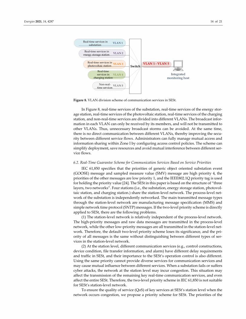
Energies 2021, 14, 4287 14 of 21
Figure 8. VLAN division scheme of communication services in SESt.
In Figure 8, real‐time services of the substation, real‐time services of the energy stor‐
age station, real‐time services of the photovoltaic station, real‐time services of the charging
station, and non‐real‐time services are divided into different VLANs. The broadcast infor‐
mation in each VLAN can only be received by its members, and will not be transmitted to
other VLANs. Thus, unnecessary broadcast storms can be avoided. At the same time,
there is no direct communication between different VLANs, thereby improving the secu‐
rity between different service flows. Administrators can fully manage mutual access and
information sharing within Zone I by configuring access control policies. The scheme can
simplify deployment, save resources and avoid mutual interference between different ser‐
vice flows.
6.2. Real‐Time Guarantee Scheme for Communication Services Based on Service Priorities
IEC 61,850 specifies that the priorities of generic object oriented substation event
(GOOSE) message and sampled measure value (SMV) message are high priority 4, the
priorities of the other messages are low priority 1, and the IEEE802.1Q priority tag is used
for holding the priority value [24]. The SESt in this paper is based on the structure of “three
layers, two networks”. Four stations (i.e., the substation, energy storage station, photovol‐
taic station, and charging station.) share the station‐level network. The process‐level net‐
work of the substation is independently networked. The main transmitted message types
through the station‐level network are manufacturing message specification (MMS) and
simple network time protocol (SNTP) messages. If the two‐level priority scheme is directly
applied to SESt, there are the following problems.
(1) The station‐level network is relatively independent of the process‐level network.
The high‐priority messages and raw data messages are transmitted in the process‐level
network, while the other low‐priority messages are all transmitted in the station‐level net‐
work. Therefore, the default two‐level priority scheme loses its significance, and the pri‐
ority of all messages is the same without distinguishing between different types of ser‐
vices in the station‐level network.
(2) At the station level, different communication services (e.g., control constructions,
device condition, file transfer information, and alarm) have different delay requirements
and traffic in SESt, and their importance to the SESt’s operation control is also different.
Using the same priority cannot provide diverse services for communication services and
may cause mutual influence between different services. When a substation fails or suffers
cyber attacks, the network at the station level may incur congestion. This situation may
affect the transmission of the remaining key real‐time communication services, and even
affect the entire SESt. Therefore, the two‐level priority scheme in IEC 61,850 is not suitable
for SESt’s station‐level network.
To ensure the quality of service (QoS) of key services at SESt’s station level when the
network occurs congestion, we propose a priority scheme for SESt. The priorities of the
Switch
Real‐time services in substation
Real‐time services in energy storage station
Real‐time services in photovoltaic station
Real‐time services in
charging station
Non‐real‐time services
Integrated monitoring host
VLAN 1
VLAN 2
VLAN 3
VLAN 4
VLAN 5
VLAN 1 ‐ VLAN 5

Energies 2021, 14, 4287 15 of 21
services at SESt’s station level are assigned considering the delay requirements, the im‐
portance to SESt’s operation control, and the traffic in this paper. Meanwhile, its queue
scheduling method is presented.
6.2.1. New Priorities for Communication Services at the Station Level
The communication services at the station level do not have high real‐time require‐
ments, but different types of services have different real‐time requirements. Therefore, the
priority scheme based on communication services is more accurate and can better meet
the real‐time requirements of communication services at SESt’s station level.
One packet based on the IEEE802.1Q protocol inserts a 4‐byte label after the MAC of
the Ethernet frame header. The 3‐bit priority field in the label can set 8 priorities, namely
priority 0~7. However, for the unmarked frame (i.e., the frame does not contain the IEEE
802.1q tag), the switch will automatically add a label to the data frame after recognition,
and the priority field in the label defaults to 1. Priority 0 is not recommended, because it
may cause unpredictable delay. Therefore, the service priority scheme in this paper is se‐
lected from priority 1 to 7.
From the perspective of the safe and stable operation of SESt, the transmission se‐
quence of service can be determined according to the importance to the operation control
of SESt, real‐time requirement, and traffic of service flow. The service priority scheme in
this paper and the priority scheme in IEC61850 are shown in Table 3. The detailed analysis
can refer to our previous work [25].
Table 3. The service priority scheme in this paper and the priority scheme in IEC61850.
Types of Messages Service Information Priorities in Our Scheme Priorities in IEC 61,850
access control instruction
messages control instructions 7 4
medium speed messages
protection action, breaker position 6 4
status information, measurement infor‐
mation 4 4
low speed messages
warning information 5 4
non‐electrical measurement infor‐
mation, modification of the set value 3 4
time synchronization mes‐
sages time tick 2 1
file transfer messages other files and logs 1 1
6.2.2. Switch Queue Scheduling Algorithm for New Service Priorities
At present, the strict priority queue (SPQ) scheduling algorithm is commonly used
in power industry switches. This algorithm preferentially processes the packets in the
high‐priority queue. Only when the high‐priority queue is empty, will the packets in the
low‐priority queue be processed [26]. If the SPQ scheduling algorithm is used in SESt, all
the other real‐time services will be affected once a certain kind of real‐time service traffic
increases sharply. This is because all the real‐time services have no different priority.
Therefore, it is necessary to design a new switch queue scheduling algorithm to fit the
new service priority scheme. For this purpose, this paper proposes a queue scheduling
algorithm of priority deficit weighted round robin (PDWRR), which combines the ad‐
vantages of dynamic weighted round robin (DWRR) [27] and SPQ. The algorithm princi‐
ple of PDWRR is illustrated in Figure 9, and the pseudo‐code of PDWRR is shown as Al‐
gorithm 1.

Energies 2021, 14, 4287 16 of 21
Figure 9. Algorithm principle diagram of PDWRR.
Algorithm 1 PDWRR
Input: packets;
Output: packets;
1: When a packet arrives, the packet classifier checks the IEEE802.1Q user priority label in the packet
header and puts the packet into the corresponding real queue Qi;
2: According to the queue priority, queue traffic and service delay requirements, the queues (i.e., Q2, Q3,
Q4, Q5, Q6, Q7) participating in DWRR scheduling are assigned reasonable weights;
3: The scheduling processor first checks the queue (i.e., Q2~Q7). If there is a packet, the corresponding
number of packets are taken from the queue (i.e., Q2~Q7) according to DWRR scheduling rule to form a virtual
queue (i.e., VQ) and forward the packet;
4: When there are no packets in the queue (i.e., Q2~Q7) and there are packets in the queue (i.e., Q1), the
packets in the queue (i.e., Q1) are forwarded;
5: Repeat from step 1 until all queues are empty and no packet arrives.
In Algorithm 1, the low‐priority queue stores non‐real‐time service information (e.g.,
auxiliary control device data, primary equipment condition monitoring data, and record‐
ing data), the high‐priority queue stores real‐time service information (e.g., control in‐
structions, protection action, breaker position, status information, measurement value,
warning information, non‐electrical measurement value, modification of the set value,
time tick). The polling and weighting of DWRR can allocate bandwidth to each queue
fairly so that all real‐time services have the opportunity to be scheduled. When any kind
of real‐time traffic increases sharply, the QoS of other real‐time services cannot be affected.
Thus, the impact of flood attacks on SESt will be reduced. Meanwhile, the strict priority
strategy of SPQ guarantees the real‐time performance of real‐time services to the greatest
extent. PDWRR combines the advantages of DWRR and SPQ. It gives an absolute priority
and predetermined bandwidth to high real‐time services. Hence, the high real‐time ser‐
vice can be transmitted without interfering with each other. The QoS requirements of mul‐
tiple services at SESt’s station‐level network can be met. The simulation experiment and
results are in our previous work [25].
In practice, when the new prioritization method and queue scheduling algorithm
(i.e., PDWRR) are used, the queue scheduling algorithm program of switches needs to be
upgraded. Meanwhile, VLANs and service priorities need to be configured. When initial‐
izing the network, 5 VLANs are divided at the switch of SESt’s station level, and the ser‐
vice flows are allocated to the corresponding VLAN according to Section 6.1. Moreover,
the priorities are assigned according to Table 2, and the scheduling queue scheme and
weight for each VLAN are specified according to Algorithm 1. It should be noted that the
data of each substation are transmitted to the integrated monitoring system through
switches. Hence, the port of the switch connected to the integrated monitoring system
need to be configured into all the five VLANs. Considering the compatibility with existing
switches, the new priorities are all greater than or equal to 4. Therefore, when switches
used in practice do not support the new priorities and queue scheduling algorithm, the
Que6
Que4
Que2
Que1
DWRRscheduler
PQscheduler
Que5
Que3
Packet classifier
Input
Output
Low priority
High priority
Que7
Weight W6
WeightW5
Weight W4
Weight W3
Weight W2
Weight W1

Energies 2021, 14, 4287 17 of 21
data forwarding can still use the method before improvement without distinguishing the
types of services at the station level.
6.3. An Enhancing Cyber Security Scheme Based on Improved IEC 62351
IEC has presented IEC 62351 [28–31] for the data and communication security of the
IEC 61,850 substations. However, the security capabilities provided by IEC 62351 have the
following deficiencies:
(1) The security measures defined by IEC 62351 do not cover all the security require‐
ments of SESt.
(2) Due to the limited processing ability of embedded devices, some recommended se‐
curity algorithms (e.g., the high complex RSA algorithm) in IEC 62351 are not suitable
for SESt.
6.3.1. Security Measures for Communications within the Station Level
Section 6.2 has pointed out that the communication services use the MMS protocol at
the station level. MMS is an application protocol based on TCP/IP. Integrity, non‐repudi‐
ation, authenticity, availability, and confidentiality are its main security requirements. Ac‐
cording to the improvement scheme proposed by IEC 62351‐4 [30] and reference [32], this
paper proposes the security measures for SESt’s station level as follows:
(1) To protect the authenticity of MMS, we enable the sender‐ACSE‐requirements field
and responder‐ACSE‐requirements field of the authentication functional unit (FU) of
the association control service element (ACSE). Meanwhile, we define the data struc‐
ture MMS_Authentication‐value where the signature value is stored.
(2) To protect the integrity of MMS, we adopt the SM3 algorithm to hash MMS messages.
(3) To ensure the authenticity of device identity, we add a unique identifier of the device
to the reserved sequence field of MMS messages.
(4) Because SM2 has the advantages of higher security, faster operation, and less re‐
source consumption, to ensure the integrity, non‐repudiation, and confidentiality of
messages, we adopt the SM2 algorithm instead of the RSA algorithm defined in IEC
62351 to sign and encrypt high‐speed MMS messages.
(5) For the low‐speed MMS messages, we adopt the improved TLS. For the medium‐
speed MMS messages, we adopt the method of signature‐then‐encryption on the
sending side and decryption‐then‐authentication on the receiving side.
(6) To protect MMS messages against replay attacks, we adopt the timestamp verifica‐
tion to distinguish between real‐time packets and obsolete packets.
These measures can ensure the authenticity, integrity, confidentiality, and non‐repu‐
diation of MMS at SESt’s station level, and meet the real‐time communication require‐
ments [32].
6.3.2. Security Measures for Communications within the Process Level
Most of the secondary devices at the process level are embedded terminals. Their
computing resources are limited. The manufacturers usually lack the ability to develop
security protection technologies. Thus, it is difficult to add the security protection
measures shown in Figure 5. To ensure the real‐time performance and security of com‐
munication services at the process level, we recommend that the process level devices and
the bay level devices in SESt use traditional point‐to‐point optical fiber communication
without configuring the switches at the process level. This scheme can greatly reduce the
cyber security risk.
If the process level and the bay level of SESt use Ethernet for communication, we can
refer to GOOSE/SMV security measures proposed in [32]. By adopting the security
measures in [32], the authenticity of device identity and message integrity can be ensured.
In addition, the authenticity, integrity, availability, and non‐repudiation of communica‐
tion services at the process level can also be guaranteed.

Energies 2021, 14, 4287 18 of 21
The real‐time performance of the above cyber security measures based on improved
IEC 62351 was analyzed and verified in our previous work [32]. Interested readers can
consult this.
7. Security Analysis
The proposed cyber security protection solutions, which not only can guarantee the
confidentiality of data but also can resist various attacks, and reduce SESt’s cyber security
risk.
(1) Resistance to eavesdropping
SM2 algorithm ensures the confidentiality of high‐speed MMS messages. Improved
TLS is adopted to ensure the confidentiality of low‐speed MMS messages. Medium‐speed
MMS messages adopt the encryption algorithm to ensure their confidentiality. These
measures can effectively prevent data from being stolen.
(2) Resistance to unauthorized access, interception, forgery, tampering
The security zoning and isolation scheme in this paper can protect SESt against un‐
authorized access and interception. SM3 algorithm can protect MMS messages against
unauthorized modification. Thus, forgery and tampering can be avoided. Furthermore,
we adopt peer entity authentication based on the SM2 algorithm to verify the integrity
and authenticity of MMS messages. In this way, attackers cannot arbitrarily tamper with
or forge communication messages.
(3) Resistance to flood attack
The real‐time guarantee scheme for communication services based on service priori‐
ties has the ability to isolate malicious traffic and can ensure the real‐time and reliable
transmission of key services in SESt’s station level once the network is congested.
(4) Non‐repudiation
The unique identifier of the sender ensures that the device cannot deny its participa‐
tion in the communication, which effectively protects SESt against repudiation attacks.
(5) Resistance to replay attack
Timestamp checking is used for distinguishing current packages and outdated pack‐
ages, which effectively resists replay attacks.
8. Conclusions
SESt has diverse communication services, complex data exchanges, and wide expo‐
sure. Thus, SESt is vulnerable to cyber attacks. To ensure the safe operation of SESt, this
paper studies the cyber security issues for multi‐station integrated SESt. Firstly, the com‐
position of SESt is presented and the secondary system architecture is designed. The de‐
signed secondary system architecture takes relative independence and shareability of re‐
sources and functions into account. Then, the data exchanges of SESt are analyzed consid‐
ering the requirements of information collection and transmission of SESt. Furthermore,
cyber security threats and requirements of SESt are illustrated for determining SESt’s se‐
curity requirements. On this basis, the cyber security protection principle and protection
system are proposed. The protection system design takes the current technical level and
realizability into account and covers cyber security solutions for each layer of SESt. Fi‐
nally, the security zoning and isolation scheme and reinforcement solutions are proposed.
The security zoning and isolation scheme not only follows the traditional security protec‐
tion principle of the power secondary system, but also takes the specificities of the charg‐
ing station being placed outside and the data center station having both internal and ex‐
ternal services into account. The proposed reinforcement solutions can protect communi‐
cation services of SESt’s station level against flood attacks, tampering attacks, and forgery
attacks. Thus, the integrity of messages of SESt’s station level and the availability of real‐
time communication services under flood attacks are ensured.

Energies 2021, 14, 4287 19 of 21
This work belongs to the category of passive defense, and cannot deal with DoS at‐
tacks (e.g., malformed message attacks) other than flood attacks. The solution of secret
key management is not involved in this paper, so we suggest using the existing power
public key infrastructure (PKI) in practice. The active security defense measures and dis‐
tributed secret‐key management schemes for SESt would be the future study topics.
Author Contributions: Investigation, Y.C.; resources, Y.C., Q.L., Y.X. and F.L.; conceptualization,
Y.C.; methodology, Y.C.; writing and editing, Y.C.; Editing, J.L.; supervision, J.L. and H.L. All au‐
thors have read and agreed to the published version of the manuscript.
Funding: This research received no external funding.
Institutional Review Board Statement: Not applicable.
Informed Consent Statement: Not applicable.
Data Availability Statement: This study did not report any data.
Acknowledgments: This work is supported by National Natural Science Foundation of China (Re‐
search on the evolution mechanism and early defense of cascading failures across spaces caused by
coordinated cyberattacks in Grid CPS, No. 51977155).
Conflicts of Interest: The authors declare no conflict of interest.
Appendix A
Table A1. Information corresponding to each number in Figure 4.
Number Information
1 Time synchronization data
2, 19
User login information, operation information, network connection infor‐
mation, permission change information, etc.; network device topology infor‐
mation; CPU utilization, memory utilization, etc.; security events and config‐
uration information of the device’s own policy
3
Energy meter data, working status of charging pile, voltage, current, power,
etc.; fault statistics (e.g., overvoltage, undervoltage, overcurrent, etc.); alarm
information; switching status of power supply system in charging station,
protection signals, etc.
4
Commands to control the start and stop of charging piles, time synchroniza‐
tion data, etc.; commands to control the opening and closing of circuit break‐
ers and disconnectors of the power distribution system
5 Voltage, current and power of photovoltaic station
6 Commands to control the opening and closing of grid‐connected circuit
breakers, commands to regulate the power of power station
7 Status and measurement information of battery cells, modules and battery
clusters
8 Commands to cut off the charge and discharge circuit, force cooling; time syn‐
chronization
9, 15
Data of substation automation system, microcomputer five‐proof system,
wide area phasor measurement device, relay protection device, self‐control
device and centralized control station; fire alarm information
10, 16
Commands to control the closing and opening of the disconnectors, on‐load
tap‐changer of the main transformer and station transformer, reset of the pro‐
tection/automatic devices, etc.
11, 20 the voltage on high and low voltage side of the main transformer, current,
and load

Energies 2021, 14, 4287 20 of 21
12, 21 Video, security, access control and other information; indoor and outdoor
temperature and humidity, wind power, SF6 gas concentration, etc.
13, 21 Monitoring information for transformers/capacitors, circuit breakers, and ca‐
pacitive devices/arrester, etc.
14, 22, 23 power consumption data
17, 18, 24 the changes in power parameters caused by large disturbances.
25, 28, 29 Production management data and information
26 Data for SCADA system analysis
27 Data of other substations
30, 31 Data required by social enterprises
32, 33 Data used for exchanging between data center stations
References
1. Samuel, P. A smarter planet. Vital Speeches of the Day. 2009; pp. 45–47. Available online: https://xueshu.baidu.com/us‐
ercenter/paper/show?paperid=cb16acff8f39d0b7194b1587b67d18cf&site=xueshu_se (accessed on 6 December 2009).
2. Han, X.P. When energy is filled with wisdom‐by China Energy Net CIO. Chin. Foreign Entrepreneurs. 2009, 16–21. Available
online: http://www.cnki.com.cn/Article/CJFDTotal‐ZWQY200909003.htm (accessed on 10 December 2009).
3. State Grid Corporation of China. Grasp the Implementation at a High Starting Point and Promote the Construction of World‐
class Energy Internet Enterprises [EB/OL]. 2018. Available online:
http://www.sgcc.com.cn/html/sgcc_main/col2018032137/2018‐04/28/20180428120759524476065_1.shtml (accessed on 9 Novem‐
ber 2009).
4. State Grid Corporation of China. Opinions on Speeding up the Construction of World‐Class Energy Internet Enterprises in the
New‐Era Reform “Starting Again” [EB/OL]. 2019. Available online: http://www.tanpaifang.com/tan‐
guwen/2019/0121/62904.html (accessed on 10 November 2009).
5. Wang, J.Y.; Guo, J.H.; Cao, J.W.; Gao, L.Y.; Hu, Z.W.; Zhou, J.; Ming, Y.Y.; Fang, Z.W. Review on information and communica‐
tion key technologies of energy internet. Smart Grid. 2015, 3, 473–485. doi:10.14171/j.2095‐5944.sg.2015.06.002).
6. Deng, W.; Fu, Y.F.; Wang, X.Z. Energy internet architecture and security analysis. In Proceedings of the 2015 Annual Infor‐
mation Conference of the Power Industry, Beijing, China, 23 September 2015; pp. 289–291.
7. Liao, H.M.; Xuan, J.X.; Zhen, P.; Li, L.L. Overview of ubiquitous power internet of things information security. Electr. Power Inf.
Commun. Technol. 2019, 17, 18–23.
8. Harnett, K.; Harris, B.; Chin, D.; Watson, G. DOE/DHS/DOT Volpe Technical Meeting on Electric Vehicle and Charging Station
Cybersecurity Report. Available online: https://rosap.ntl.bts.gov/view/dot/34991 (accessed on 5 July 2020).
9. Sebastian, D.J.; Hahn, A.; Liu, C.C. Assessing cyber‐physical risks of IoT‐based energy devices in grid operations. IEEE Access.
2020, 8, 61161–61173.
10. Saleem, Y.; Crespi, N.; Rehmani, M.H.; Copeland, R. Internet of things‐aided smart grid: Technologies, architectures, applica‐
tions, prototypes, and future research directions. IEEE Access. 2019, 7, 62962–63003.
11. Zhu, S.J.; Liu, H.M.; Tang, Y.; Wang, H.; Tang, J.H. Modeling and collaborative optimal operation strategy for multiple energy
stations of regional integrated energy system. Power Demand Side Manag. 2019, 21, 60–66.
12. Wang, B.Y.; Zhang, Y.; Liu, M.B.; Mi, X.R. Research on the multi‐station integration operation mode. Electr. Power Inf. Commun.
Technol. 2019, 17, 41–45.
13. Zhang, S.; Ma, Y.; Yang, J.; Zhou, M.; Qin, J.; Li, H. Comprehensive evaluation method of safety and benefit for multi‐station
integration. In Proceedings of the 2019 IEEE Sustainable Power and Energy Conference (iSPEC), Beijing, China, 21–23 Novem‐
ber 2019; pp. 2618–2623.
14. Li, H.; Ru, Y.Q.; Li, Y.K.; Guo, H. Information security protection design of electric vehicles charging station. Appl. Mech. Mater.
2015, 741, 681–686, doi:10.4028/www.scientific.net/AMM.741.681.
15. Lei, W.J. Research on security mechanism of the 3G and application security of the mobile terminals. Electron. Des. Eng. 2013,
14, 93–95.
16. Wang, L. Security protection and reinforcement technology of regional scheduling SCADA/EMS. Fujian Electr. Power Electr. Eng.
2006, 26, 35–37.
17. Zou, Z.W.; Chen, J.; Hou, Y.S.; Song, P.P.; He, L.; Yang, H.T.; Wang, B. Design and implementation of a new intelligent substa‐
tion network security defense system. In Proceedings of the 2019 IEEE 4th Advanced Information Technology, Electronic and
Automation Control Conference (IAEAC), Chengdu, China, 20–22 December 2019; pp. 2709–2713.
18. Peng, J. Simple analysis on electricity saving principle of electromagnetic M‐type power saver and effect testing. Power Electron.
2014, 48, 41–43.
19. Xu, W.B.; Cheng, H.F.; Bai, Z.H.; Miao, C.H.; Sun, F.C. Optimal design and operation of energy storage power station under
multi‐station fusion mode. Power Supply 2019, 36, 84–91.

Energies 2021, 14, 4287 21 of 21
20. National Assembly of the PRC. Regulations on the safety protection of electric power monitoring system. In National Develop‐
ment and Reform Commission Order No. 14; National Assembly of the PRC: Beijing, China, 2014.
21. State Grid Corporation of China. Technical Regulations for the Connection of Photovoltaic Power Stations to the Grid: Q/GDW‐1617;
State Grid Corporation of China: Beijing, China, 2015.
22. State Grid Corporation of China. Technical Regulations for Connecting the Electrochemical Energy Storage System to the Grid: GB/T‐
36547; State Grid Corporation of China: Beijing, China, 2018.
23. China Electricity Council. Design Specification for Electric Vehicle Charging Station: GB‐50966; China Electricity Council: Beijing,
China, 2014.
24. IEC 61850‐Communication Networks and Systems in Substations‐Part 9‐2: Specific Communication Service Mapping (SCSM)–
Sampled Values Over ISO. 2003. Available online: https://www.doc88.com/p‐5837246298671.html (accessed on 20 December
2009).
25. Li, J.E.; Lu, Q.Y.; Chen, Y.R.; Lin, H.; Xia, Y.; Li, F.Y. A Priority Scheme of Communication Services in Smart Energy Station and
PDWRR Queue Scheduling Method. Patent 202010450544.3, 25 May 2020.
26. Zhong, X.W.; Chen, Z.H.; Wang, D.; Peng, H. Research on information flow queue scheduling strategy of substation communi‐
cation network. Heilongjiang Electr. Power 2017, 39, 307–312.
27. Shreedhar, M.; Varghese, G. Efficient fair queuing using deficit round‐robin. IEEE/ACM Trans. Net. 1996. 4, 375‐385.
28. IEC 62351‐3‐Data and Communication Security‐Part 3: Profiles Including TCP/IP. 2005. Available online: https://www.renren‐
doc.com/p‐80088080.html (accessed on 20 December 2009).
29. IEC 62351‐4‐Data and Communication Security‐Part 4: Profiles Including MMS. 2005. Available online:
https://www.doc88.com/p‐9405018069411.html?r=1 (accessed on 20 December 2009).
30. IEC 62351‐4‐Data and Communication Security‐Part 5: Security for IEC 61850‐5 and Derivatives. 2005. Available online:
https://www.doc88.com/p‐9405018069411.html?r=1 (accessed on 20 December 2009).
31. IEC 62351‐6‐Data and Communication Security‐Part 6: Security for IEC 61850 Profiles. 2020. Available online:
https://www.doc88.com/p‐18361830929742.html (accessed on 20 December 2009).
32. Zhang, J.; Li, J.E.; Chen, X.; Ni, M.; Wang, T.; Luo, J.B. A security scheme for intelligent substation communications considering
real‐time performance. J. Mod. Power Syst. Clean Energy 2019, 7, 948–961.