Embed Size (px)
Citation preview
Date: <Enter Date>To: Subcommittee D02.B0 members Tech Contact: Lyle Bowman, <[email protected]>/415-479-3004Work Item #: WK49666Ballot Action: New test method (VH)Rationale: Replacement for older test method (VG)
Standard Test Method for Evaluation of Automotive Engine Oils for Inhibition of Deposit Formation in the Sequence VH Spark-Ignition Engine Fueled with Gasoline and Operated Under Low-Temperature, Light-Duty Conditions1
This standard is issued under the fixed designation DXXXX; the number immediately following the designation indicates the year of original adoption or, in the case of revision, the year of last revision. A number in parentheses indicates the year of last reapproval. A superscript epsilon (ε) indicates an editorial change since the last revision or reapproval.
INTRODUCTION
Portions of this test method are written for use by laboratories that make use of ASTM Test Monitoring Center (TMC 2) services (see Annex A1).
The TMC provides reference oils, and engineering and statistical services to laboratories that desire to produce test results that are statistically similar to those produced by laboratories previously calibrated by the TMC.
In general, the Test Purchaser decides if a calibrated test stand is to be used. Organizations such as the American Chemistry Council require that a laboratory use the TMC services as part of their test registration process. In addition, the American Petroleum Institute and the Gear Lubricant Review Committee of the Lubricant Review Institute (SAE International) require that a laboratory use the TMC services in seeking qualification of oils against their specifications.
The advantage of using the TMC services to calibrate test stands is that the test laboratory (and hence the Test Purchaser) has an assurance that the test stand was operating at the proper level of test severity. It should also be borne in mind that results obtained in a non calibrated test stand may not be the same as those obtained in a test stand participating in the ASTM TMC services process.
Laboratories that choose not to use the TMC services may simply disregard these portions.
1. Scope1.1 This test method is commonly referred to as the Sequence VH3 test, and it has been correlated with the Sequence VG
test. The Sequence VG test was previously correlated with vehicles used in stop-and-go service prior to 1996, particularly with regard to sludge and varnish formation4. It is one of the test methods required to evaluate oils intended to satisfy the API SL performance category.
1This test method is under the jurisdiction of ASTM Committee D02 on Petroleum Products, Liquid Fuels, and Lubricants and is the direct responsibility of Subcommittee D02.B0.01 on Passenger Car Engine Oils.
22ASTM Test Monitoring Center, 6555 Penn Avenue, Pittsburgh, PA 15206-4489. www.astmtmc.cmu.edu.
3Until the next revision of this test method, the ASTM Test Monitoring Center will update changes in the test method by means of information letters. Information letters may be obtained from the ASTM Test Monitoring Center, 6555 Penn Ave.,Pittsburgh, PA 15206-4489. Attention: Administrator. This edition incorporates revisions in all information Letters through No.__
4 For referenced ASTM standards, visit the ASTM website, www.astm.org, or contact ASTM Customer Service at [email protected]. For Annual Book of ASTM Standards volume information, refer to the standard's Document Summary page on the ASTM website.
1.2 The values stated in SI units are to be regarded as the standard. No other units of measurement are included in this standard.
1.2.1 Exception—Where there is no direct SI equivalent such as screw threads, national pipe threads/diameters, tubing size, or specified single source equipment.
1.3 This standard does not purport to address all of the safety concerns, if any, associated with its use. It is the responsibility of the user of this standard to establish appropriate safety and health practices and determine the applicability of regulatory limitations prior to use. Specific hazard statements are given in 7.7, 7.7.3, 7.7.4, 7.7.5, 8.3.4.2, 8.4.4.3, 9.2.6, 9.3.4.5, 12.1.1.7, 12.2.1.4, A5.3.4 and A5.3.5.
1.4 A Table of Contents follows:
Scope 1Referenced Documents 2Terminology 3Summary of Test Method 4Significance and Use 5Apparatus (General Description) 6Apparatus (The Test Engine) 7Sequence VH Test Engine 7.1
Required New Engine Parts 7.2
Reusable Engine Parts 7.3
Specially Fabricated Engine Parts 7.4
Special Engine Measurement and AssemblyEquipment
7.5
Miscellaneous Engine Components-Preparation 7.6
Solvents and Cleaners Required 7.7
Assembling the Test Engine-Preparations 7.8
Assembling the Test Engine-Installations 7.9
Engine Installation on the Test Stand 7.10
Engine Fluids (Supply/Discharge Systems) 8Intake Air 8.1
Fuel and Fuel System 8.2
Engine Oil and Engine Oil System 8.3
Coolants 8.4
Measurement Instrumentation 9Temperatures 9.1
Pressures 9.2
Flow Rates 9.3
Fuel Consumption 9.4
Speed and Load 9.5
Exhaust Gas 9.6
Humidity 9.7
Miscellaneous Laboratory Equipment 10Test Stand Calibration 11Test Procedure 12Pre-Test Procedure 12.1
Engine Operating Procedure 12.2
Periodic Measurements and Functions 12.3
Special Maintenance Procedures 12.4
Diagnostic Data Review 12.5
End of Test Procedure 12.6
Interpretation of Test Results 13Parts Rating Area-Environment 13.1
Sludge Ratings 13.2
Varnish Ratings 13.3
Clogging 13.4
Sticking 13.5
Used Oil Analyses 13.6
Assessment of Test Validity 14
General14.1
Used Oil Analyses-Interpretation 14.2
Blowby Flow Rate 14.3
Manifold Absolute Pressure 14.4
Fuel Consumption Rate 14.5
Oil Consumption 14.6
Engine Parts Replacement 14.7
Quality Index 14.8
Final Test Report 15Report Forms 15.1
Precision and Bias 16Keywords 17ANNEXES
ASTM TMC - Organization
ASTM TMC – Calibration Procedures
ASTM TMC – Maintenance Activities
ASTM TMC – Related Information
Annex A1
Annex A2
Annex A3
Annex A4Safety Precautions Annex A5
Control and Data Acquisition Requirements Annex A6
Detailed Specifications and Photographs of Apparatus
Annex A7
Special Service Tools for the Test Engine Annex A8
Test Engine Part Number Listing Annex A9
External Oil Heat Exchanger Cleaning Technique
Annex A10
Sequence VH Report Forms and Data Dictionary Annex A11
Dipstick Calibration Annex A12
Critical Part Supplier List Annex A13
Operational Data Log-Engine Oil Annex A14
Rating Worksheets Annex A15
Fuel Injector Flow Measurements Annex A16
APPENDIXES
Piston and Ring Measurements Record Forms Appendix X1
Sources of Materials and Information Appendix X22. Referenced Documents
2.1 ASTM Standards: 5
D86 Test Method for Distillation of Petroleum Products at Atmospheric PressureD235 Specification for Mineral Spirits (Petroleum Spirits) (Hydrocarbon Dry Cleaning Solvent)D287 Test Method for API Gravity of Crude Petroleum and Petroleum Products (Hydrometer Method)D323 Test Method for Vapor Pressure of Petroleum Products (Reid Method)D381 Test Method for Gum Content in Fuels by Jet EvaporationD445 Test Method for Kinematic Viscosity of Transparent and Opaque Liquids (and Calculation of Dynamic Viscosity)D525 Test Method for Oxidation Stability of Gasoline (Induction Period Method)D873 Test Method for Oxidation Stability of Aviation Fuels (Potential Residue Method)D1266 Test Method for Sulfur in Petroleum Products (Lamp Method)D1298 Test Method for Density, Relative Density, or API Gravity of Crude Petroleum and Liquid Petroleum Products by Hydrometer MethodD2622 Test Method for Sulfur in Petroleum Products by Wavelength Dispersive X-ray Fluorescence SpectrometryD2789 Test Method for Hydrocarbon Types in Low Olefinic Gasoline by Mass SpectrometryD3237 Test Method for Lead in Gasoline by Atomic Absorption SpectroscopyD3525 Test Method for Gasoline Diluent in Used Gasoline Engine Oils by Gas ChromatographyD4057 Practice for Manual Sampling of Petroleum and Petroleum ProductsD4175 Terminology Relating to Petroleum, Petroleum Products, and LubricantsD4294 Test Method for Sulfur in Petroleum and Petroleum Products by Energy Dispersive X-ray Fluorescence SpectrometryD4485 Specification for Performance of Active API Service Category Engine OilsD5059 Test Methods for Lead in Gasoline by X-Ray SpectroscopyD5185 Test Method for Multielement Determination of Used and Unused Lubricating Oils and Base Oils by Inductively Coupled Plasma Atomic Emission Spectrometry (ICP-AES)
5 Available from American National Standards Institute (ANSI), 25 W. 43rd St., 4th Floor, New York, NY 10036.
D6304 Test Method for Determination of Water in Petroleum Products, Lubricating Oils, and Additives by Coulometric Karl Fischer Titration
2.2 ANSI Standard6 ANSI MC96.1 Temperature Measurement-Thermocouples
2.3 Other ASTM Documents:ASTM Deposit Rating Manual 20 (Formerly CRC Manual 20) 7
3. Terminology
3.1 Definitions:3.1.1 air-fuel ratio, n—in internal combustion engines, the mass ratio of air-to-fuel in the mixture being inducted into the
combustion chambers. 3.1.1.1 Discussion—In this test method, air-fuel ratio (AFR), is controlled by the engine control module. D4175
3.1.2 blowby, n—in internal combustion engines, that portion of the combustion products and unburned air/fuel mixture that leaks past piston rings into the engine crankcase during operation. D4175
3.1.3 clogging, n—the restriction of a flow path due to the accumulation of material along the flow path boundaries.D4175
3.1.4 cold-stuck piston ring, n—in internal combustion engines, a piston ring that is stuck when the piston and ring are at room temperature, but inspection shows that it was free during engine operation.
3.1.4.1 Discussion—A cold-stuck piston ring cannot be moved with moderate finger pressure. It is characterized by a polished face over its entire circumference, indicating essentially no blowby passed over the ring face during engine operation.
D4175 3.1.5 debris, n—in internal combustion engines, solid contaminant materials unintentionally introduced into the engine or
resulting from wear. 3.1.5.1 Discussion—Examples include such things as gasket material, silicone sealer, towel threads, and metal particles. D4175
3.1.6 filtering, n—in data acquisition, a means of attenuating signals in a given frequency range. They can be mechanical (volume tank, spring, mass) or electrical (capacitance, inductance) or digital (mathematical formulas), or a combination thereof. Typically, a low-pass filter attenuates the unwanted high frequency noise. D4175
3.1.7 hot-stuck piston ring, n—in internal combustion engines, a piston ring that is stuck when the piston and ring are at room temperature, and inspection shows that it was stuck during engine operation.
3.1.7.1 Discussion—The portion of the ring that is stuck cannot be moved with moderate finger pressure. A hot-stuck piston ring is characterized by varnish or carbon across some portion of its face, indicating that portion of the ring was not contacting the cylinder wall during engine operation. D4175
3.1.8 knock, n—in a spark ignition engine, abnormal combustion, often producing audible sound, caused by autoignition of the air/fuel mixture. D4175
3.1.9 out of specification data, n—in data acquisition, sampled value of a monitored test parameter that has deviated beyond the procedural limits. D4175 3.1.10 reading, n—in data acquisition, the reduction of data points that represent the operating conditions observed in the time period as defined in the test procedure. D41753.1.11 scoring, n—in tribology, a severe form of wear characterized by the formation of extensive grooves and scratches in
the direction of sliding. D41753.1.12 scuffing, n—in lubrication, damage caused by instantaneous localized welding between surfaces in relative motion
that does not result in immobilization of the parts. D41753.1.13 sludge, n—in internal combustion engines, a deposit, principally composed of insoluble resins and oxidation
products from fuel combustion and the lubricant, that does not drain from engine parts but can be removed by wiping with a cloth. D4175
3.1.14 time constant, n—in data acquisition, A value which represents a measure of the time response of a system. For a first order system responding to a step change input, it is the time required for the output to reach 63.2 % of its final
6 For stock #TMCMNL20, visit the ASTM website, www.astm.org, or contact ASTM Customer Service at [email protected].
7 Ford Crown Victoria is a product of the Ford Motor Co., Dearborn, MI 48121.
value. D41753.1.15 varnish, n—in internal combustion engines, a hard, dry, generally lustrous deposit that can be removed by solvents
but not by wiping with a cloth. D41753.1.16 wear, n—loss of material from a surface, generally occurring between two surfaces in relative motion, and resulting
from mechanical or chemical action, or a combination of both. D4175 3.2 Definitions of Terms Specific to This Standard:3.2.1 enrichment, n—in internal combustion engine operation, a fuel consumption rate in excess of that which would
achieve a stoichiometric air-to-fuel ratio.3.2.1.1 Discussion—Enrichment is usually indicated by elevated CO levels and can also be detected with an extended
range air/fuel ratio sensor.3.2.2 Lambda, n—the ratio of actual air mass induced, during engine operation, divided by the theoretical air mass
requirement at the stoichiometric air-fuel ratio for the given fuel.3.2.2.1 Discussion—A Lambda value of 1.0 denotes a stoichiometric air-fuel ratio.3.2.3 low-temperature, light-duty conditions, n—indicative of engine oil and coolant temperatures that average below
normal warmed-up temperatures, and engine speeds and power outputs that average below those encountered in typical highway driving.
3.2.4 ramping, n—the prescribed rate of change of a variable when one set of operating conditions is changed to another set of operating conditions.
4. Summary of Test Method
4.1 Each VH test engine is assembled with many new parts and essentially all aspects of assembly are specified in detail.4.2 The test stand is equipped to control speed, torque, AFR, and various other operating parameters.4.3 The test is run for a total of 216 h, consisting of 54 cycles of 4 h each. Each cycle consists of three stages.4.4 While the operating conditions are varied within each cycle, overall they can be characterized as a mixture of low-
temperature and moderate-temperature, light and medium duty operating conditions.4.5 To accelerate deposit formation, the level of oxides of nitrogen in the blowby and the rate of blowby into the crankcase
are significantly increased. The fresh air breathing of the crankcase is eliminated and the oil and coolant temperatures are lowered to induce condensation of water and fuel.
4.6 The performance of the test engine oil is evaluated at the end of the test by dismantling the engine and measuring the level of engine deposit formation.
5. Significance and Use
5.1 This test method is used to evaluate an automotive engine oil's control of engine deposits under operating conditions deliberately selected to accelerate deposit formation. This VH test method was correlated with the previous VG test method, which was correlated with field service data, determined from side-by-side comparisons of two or more oils in police, taxi fleets, and delivery van services.
This document is not an ASTM standard; it is under consideration within an ASTM technical committee but has not received all approvals required to become an ASTM standard. You agree not to reproduce or circulate or quote, in whole or in part, this document outside of ASTM Committee/Society activities, or submit it to any other organization or standards bodies (whether national, international, or other) except with the approval of the Chairman of the Committee having jurisdiction and the written authorization of the President of the Society. If you do not agree with these conditions please immediately destroy all copies of the document. Copyright ASTM International, 100 Barr Harbor Drive, West Conshohocken, PA 19428. All Rights Reserved.
Designation: DXXXX – 15
8
DXXXX– 15
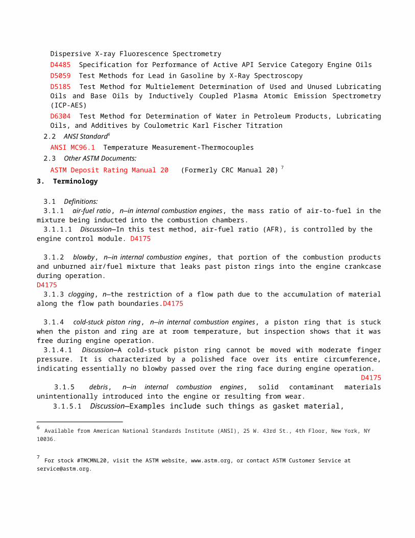
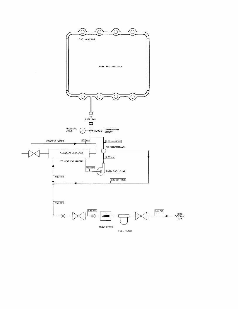
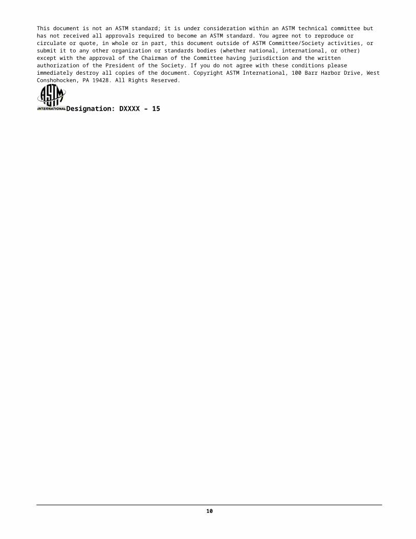
FIG. 1 Schematic of Engine Fuel System
5.2 The basic engine used in this test method is representative of many that are in modern automobiles. This factor, along with the accelerated operating conditions, should be considered when interpreting test results.
6. Apparatus (General Description)
9
DXXXX– 15
6.1 The VH test engine is a Ford, spark ignition, four stroke, eight-cylinder V configuration engine with a displacement of 4.6 L. Features of this engine include an overhead camshaft, a cross-flow fast-burn cylinder head design, two valves per cylinder and electronic port fuel injection. It is based on the Ford Motor Co. EFI Crown Victoria8 passenger car engine with a displacement of 4.6 L.
6.2 Configure the test stand to accept the VH test engine engine. All special equipment necessary for conducting this test is listed herein.
6.3 Use the appropriate air conditioning apparatus to control the temperature, pressure, and humidity of the intake air.
6.4 Use an appropriate fuel supply system (Fig. 1).6.5 The control and data acquisition system shall meet the requirements listed in Annex A6.
7. Apparatus (The Test Engine)
7.1 Sequence VH Test Engine—The test engine parts are supplied by Ford Motor Co. (A13.1). Parts from the engine may be used for as many as four tests. A detailed listing of all parts included in the kit is given in Annex A9.
7.1.1 Non-rated parts can be replaced during the test, provided the reason for replacement was not oil related.7.2 Required New Engine Parts—Use the parts listed in the engine parts list (see A9.1). Use a new gasket kit for
each test. Do not modify or alter test parts without the approval of the Sequence V Surveillance Panel. Use parts purchased in more than one batch on a first-in, first-out basis.
7.3 Reusable Engine Parts—The parts listed in A9.2 (Engine Dress Parts), A9.3 (Stand Setup Parts), A9.5 (Fasteners) and A9.6 (Engine Finish Parts) Annex can be reused (all of these can be used in numerous engine assemblies as long as they remain serviceable). Crankshaft, connecting rods, timing chain covers and cylinder heads may be used for multiple engine assemblies as long as they remain serviceable. Camshafts can be used for as many as four tests as long as they remain serviceable. As the block can be used for as many as four tests, damaged threads in the block can be corrected with commercially available thread inserts.
7.4 Specially Fabricated Engine Parts—The following subsections detail the specially fabricated engine parts required in this test method:
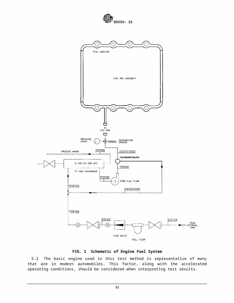
7.4.1 Intake Air System (see Fig. 2 and Figs. A7.1 and A7.2)—Intake air system shall use the parts shown in Annex A9.??
8Available from Ford and Lincoln Dealerships.
10
DXXXX– 15
NOTE 1—Dimensions are in millimetres.FIG. 2 Typical Test Stand Intake Air Supply System
7.4.2 Camshaft Baffles (see Fig. A7.3)—These are fabricated for attachment to the under side of the rocker cover. The clearance between the edges of the baffle and the (rocker arm cover) RAC permits a limited splash flow of oil to the top of the baffle and the RAC. Therefore, the dimensional accuracy of the baffle is important to minimize the influence on test severity. The camshaft baffle is available from the supplier listed in A13.2.
7.4.3 Crankcase Oil Fill Port—The crankcase oil fill port is located towards the rear of the left rocker cover. See item 8 and 9 on Fig. A7.4.
7.4.4 Dipstick and Dipstick Tube (see Fig. A7.6)—The dipstick has been modified for accurate oil level measurements. The dipstick and dipstick tube are calibrated as a pair. If either part is replaced, recalibrate the pair. Use the dipstick and dipstick tube available from the supplier listed in A13.2.
7.4.5 Oil Pan—Use a modified oil pan with removable baffles as shown in Fig. A7.7 from the supplier listed in A13.2.
7.4.6 Exhaust Manifold—The required exhaust manifolds (see an00127A13.2), exhaust manifold spacer (see A13.3) and exhaust system are shown in Figs. A7.14, A7.15, and A7.16. A universal exhaust gas oxygen (UEGO) sensor is installed in the exhaust system after each exhaust manifold. Utilize the same wide band, heated oxygen sensors for both air fuel ratio control and measurement.
7.4.7 Flywheel—Use the flywheel listed in A13.2.7.4.8 Rocker Arm Cover (RAC)—The RAC is fabricated from stainless steel and incorporates a water jacket and
bolt bosses for the camshaft baffle (see Figs. A7.3 - 7.5). The RAC, bolts, and washers supplier is listed in A13.2. As the RAC is used for multiple tests, leaks to the external cooling jacket may be repaired by welding or other suitable means. Do not modify the rated surfaces of the RAC.
7.4.9 Oil Filter—Use a 60 μm screen type oil filter with a bypass (see Fig. A7.8) available from the supplier listed in X2.1.11.
7.4.10 Oil Pan Insulation—The oil pan is covered with a fiberglass insulation to reduce the effects of ambient temperature variations. The insulation supplier is listed in A13.2.
7.5 Special Engine Measurement and Assembly Equipment—Items routinely used in laboratory and workshop are not included. Use any special tools or equipment shown in the 2000-2004 Crown Victoria Service Manual 9 for assembly. A list of these tools is shown in Annex A8. Complete any assembly instructions not detailed in Section 7 according to the instructions in the 2000-2004 Crown Victoria Service Manual.
7.5.1 Piston Ring Positioner—Use the piston ring positioner to locate the piston rings from the cylinder block deck surface by 28.5 mm. This allows the compression rings to be positioned in a consistent location in the cylinder bore before measurement. Fabricate the positioner according to the details shown in Fig. A7.9.
7.5.2 Piston Ring Grinder—A ring grinder is required for adjusting ring gaps. A suitable ring grinder is noted in 7.8.5.1.
7.5.3 PCV Valve Flow Rate Device:7.5.3.1 Use this device to verify the flow rate of the PCV valve before the test and measure the degree of
clogging after the test. Fabricate the device according to the details shown in Fig. A7.10. The device shall have a full scale accuracy of 5 % and a resolution of 0.05 L/min (see 7.6.7).
7.5.3.2 Calibrate the flow rate device once every six months against a standard traceable to NIST.7.5.4 Engine Service Tools—A complete list of special tools for the test engine is shown in Annex A8. The tools
are available from a Ford dealership or aftermarket supplier. These are designed to aid in performing several service items, in addition to the following specific service items that require special tools to perform the functions indicated (if not self-explanatory).
7.5.5 A total of four master bores are required for verifying the cylinder bore measurement device, for determining ring gap increase for the rings in cylinders 1 and 8, and for determining piston to bore clearance. Master bores are sized according to piston oversize as follows:
For 0.125 mm piston 90.345 mmFor 0.25 mm piston 90.470 mmFor 0.375 mm piston 90.595 mm
9 The sole source of supply of the Sunnen CV-616 honing machine known to the committee at this time is Sunnen Inc., 7910 Manchester, St. Louis, MO 63143.
11
DXXXX– 15
For 0.50 mm piston 90.700 mm7.5.5.1 Maintain the master bores in a temperature controlled room.7.5.6 Oil Screen Blowdown Device—Use the device available from the supplier listed in A13.3 to blow a
controlled amount of compressed air across the oil screen to remove any oil that is retained on the oil screen after allowing it to drain.
7.5.7 Engine Parts Cleaning—Clean the engine block and cylinder heads using Model Number 300 LX-P-2x dishwasher type parts cleaning machine or similar apparatus. See X2.1.12.
7.5.8 Cylinder Hone—Use a Sunnen CV-616 for cylinder bore resizing and finishing.10,11
7.5.9 Connecting Rod Heater—The piston pins are fixed to the connecting rods with an interference fit. A connecting rod heater 12,11 is required to facilitate installation of the piston pins and prevent piston distortion.
7.6 Miscellaneous Engine Components-Preparation:7.6.1 Engine Build-Up and Measurement Area-Environment—The ambient atmosphere of the engine buildup and
measurement areas shall be reasonably free of contaminants. A relatively constant temperature (within ± 3 °C) is necessary to ensure acceptable repeatability in the measurement of parts dimensions. To prevent moisture forming on cold engine parts that are brought into the buildup or measurement areas, maintain the relative humidity at a nominal maximum of 50 %.
7.6.2 Intake Manifold and Throttle Body:7.6.2.1 The required intake manifold modifications entail blocking off the EGR port (block off plate shown in
Fig. A7.13) and the coolant bypass port. Block coolant bypass port in intake manifold by tapping the hole and installing a 1/2 in. NPT pipe plug. Replace the idle air bypass motor with the idle load control system. A schematic of the system is shown in Fig. A7.12.
7.6.2.2 Clean the butterfly and bore of the throttle body with solvent (7.7.1) and air-dry before each test. Do not disassemble the throttle body as this will cause excessive wear on the components.
7.6.2.3 There is no specific life for the throttle body. However, the clearance between the bore and the butterfly will eventually increase and render the body unserviceable. When the clearance becomes too great to allow control of speed, torque, and air-fuel ratio during Stage III, discard the throttle body.
7.6.3 Rocker Arm Cover:7.6.3.1 Before each test, inspect the coolant jacket. If a deposit or film is present, then clean the RAC coolant
jacket with a commercially available de-scaling cleaner, neutralizer, and inhibitor (8.4.4.1). An example of an acceptable cleaner is detailed in 7.7.3.
7.6.3.2 Submerge the RAC in agitated organic solvent (see 7.7.2) until clean (approximately 1 h). Rinse the parts thoroughly with hot water (> 60 °C). Rinse the RAC with degreasing solvent (7.7.1) and allow to air-dry. Inspect the appearance of the inside of the RAC. If the before test rating is less than ten on the ASTM varnish rating scale (ASTM Deposit Rating Manual 20), polish the RAC with Scotch Brite General Purpose Hand Pad #744713,11 to achieve a dull finish. Rinse with degreasing solvent (7.7.1) and allow to air-dry before use.
7.6.4 Camshaft Baffle—Submerge the camshaft baffles in agitated organic solvent (see 7.7.2) until clean (approximately 1 h). Rinse the parts thoroughly with hot water (> 60 °C). Rinse the camshaft baffles with degreasing solvent (7.7.1) and allow to air-dry. Inspect the appearance of the top surface of the camshaft baffle. If the before test rating is less than ten on the ASTM varnish rating scale (ASTM Deposit Rating Manual 20), polish the camshaft baffle with Scotch Brite General Purpose Hand Pad #7447 to achieve a dull finish. Rinse with degreasing solvent (7.7.1) and allow to air-dry before use.
7.6.5 Oil Pan—Submerge the oil pan in agitated organic solvent (see 7.7.2) until clean (approximately 1 h). Rinse the part thoroughly with hot water (> 60 °C). Rinse the oil pan with degreasing solvent (7.7.1) and allow to air-dry.
10If you are aware of alternative suppliers, please provide this information to ASTM International Headquarters. Your comments will receive careful consideration at a meeting of the responsible technical committee,1 which you may attend.
11The sole source of supply of the connecting rod heater (Sunnen Model CRH-50) and pin installation tool known to the committee at this time is
Sunnen, Inc., 7910 Manchester, St. Louis, MO 63143. 12Scotch Brite is a trademark of 3M Corporate Headquarters, 3M Center, St. Paul, MN 55144-1000.
13 The sole source of supply of Penmul L460 known to the committee at this time is Penetone Corp., P.O. Box 22006, Los Angeles, CA 90022.
12
DXXXX– 15
7.6.6 Oil Pan Baffle—Submerge the oil pan baffle in agitated organic solvent (see 7.7.2) until clean (approximately 1 h). Rinse the part thoroughly with hot water (> 60 °C). Rinse the oil pan baffle with degreasing solvent (7.7.1) and allow to air-dry.
7.6.7 PCV Valve—Measure and record the flow rates of the PCV valve with the calibrated flow device described in 7.5.3 and Fig. A7.10. Measure the flow rate at (25 and 60) kPa vacuum. Because of the hysteresis in the PCV valve spring, make the vacuum adjustments in one direction only. Measure the flow rate twice and average the readings. Reject any PCV valve that does not exhibit an average flow rate of (90 to 140) L/min at 25 kPa and (30 to 50) L/min at 60 kPa.
7.6.8 Water Pump Drive System—Use the recommended external pump specified in A13.10. Plumb the external coolant system per Fig. A7.18.
7.6.9 Front Cover—Modify front cover to facilitate installation of tensioner, idler, and water pump drive belt. Since the belt is routed differently from the stock location some bolt bosses may need to be altered to clear the shorter belt and the tensioner. These bolt bosses are used to attach the front end accessory drive components that are not used for this test.
7.6.10 Oil Separators—Use Moroso separator specified in Annex XX.. Disassemble and clean with degreasing solvent (7.7.1) and allow to air-dry prior to each test.
7.6.1 Timing Chain Cover—Submerge the timing chain cover in agitated organic solvent (see 7.7.2) until clean (approximately 1 h). Rinse the part thoroughly with hot water (> 60 °C). Clean with degreasing solvent (7.7.1) and allow to air-dry.
7.7 Solvents and Cleaners Required—No substitutions for 7.7.1 – 7.7.5 are allowed. (Warning—Use adequate safety provisions with all solvents and cleaners. See Annex A5.)
7.7.1 Solvent—Use only mineral spirits meeting the requirements of Specification D235, Type II, Class C for Aromatic Content 0 % to 2 % by volume, Flash Point (61 °C, min) and Color (not darker than +25 on Saybolt Scale or 25 on Pt-Co Scale). (Warning—Combustible. Health hazard.) Obtain a Certificate of Analysis for each batch of solvent from the supplier.
7.7.2 Organic Solvent, Penmul L460. (Warning—Combustible. Health hazard.)14,11
7.7.3 Dearsol 134 Acidic Cleaner15,11 with Inhibitor, RAC cooling jacket internal cleaner. (Warning—Combustible. Health hazard.)
7.7.4 Cooling System Cleaner, Dupont or equivalent, for cleaning cooling system components external to the engine. (Warning—Caustic. Health hazard.)
7.7.5 Parts Cleaning Soap,16,11 NAT-50 or PDN-50 have been found to be acceptable. (Warning—Health hazard.)
7.8 Assembling the Test Engine-Preparations—Use the test engine obtained from the supplier in 7.1. If this is the first test on a new engine, disassemble the engine in accordance with the 2000-2004 Crown Victoria Shop Manuals. Number the connecting rod bearing caps to the corresponding cylinders. Retain the following parts from the new engine: oil pump, main bearings, connecting rod bearings, thrust washer, oil screen spacer, oil filter gasket, oil pan gasket, exhaust manifold gasket, roller followers, valve lash adjusters, rear seal housing, crankshaft gear, timing chains, tensioners, chain rails, plus the following parts that can be used for multiple tests: cylinder block, crankshaft, connecting rods, ignition ring sensor, crankshaft and camshaft timing sensors, crankshaft vibration damper, crankshaft bolt and washer, oil filter adapter and the water pump and pulley.
7.8.1 Parts Selection—Instructions concerning the use of new or used parts are detailed in 7.1.1, 7.2, and 7.3.7.8.2 Sealing Compounds—Use a silicon-based sealer as needed between the rear seal housing-cylinder block,
the cylinder block-cylinder head-front cover interfaces, cylinder head-front cover-rocker cover interfaces, and cylinder block-front cover-oil pan interfaces.
7.8.2.1 Use silicon-based sealer sparingly since it can elevate the indicated silicon content of the used oil.14 The sole source of supply of Dearsol 134 Acidic Cleaner known to the committee at this time is Dearborn Div., subsidiary of W. R. Grace and Co., 300 Genesee St., Lake Zurich, IL 60047.
15 The sole source of supply of the soap (NAT-50 or PDN-50) known to the committee at this time is Better Engineering Manufacturing, 8361 Town Court, Baltimore, MD 21236.16 The sole source of supply of Mobil EF-411 oil known to the committee at this time is Mobil Oil Corp., 3225 Gallows, Fairfax, VA 22037.
13

DXXXX– 15
NOTE 1—Non-silicon liquid or tape thread sealers can be used on bolts and plugs.7.8.3 Gaskets and Seals—Install new gaskets and seals during engine assembly.7.8.4 Block Preparations—Inspect block, including oil galleries for debris and rust. Remove any debris or rust
that is found. Remove oil gallery plugs. Removal of coolant jacket plugs is left to the discretion of the laboratory. Enlarge the chamfers around the top of the cylinder bore. Spray the block with degreasing solvent (see 7.7.1). Spray block with a 50/50 mixture of degreasing solvent (see 7.7.1) and EF-411.17,11 Install the stress plates with cylinder heads and torque to 37 N·m to 43 N·m with an additional 180° in two 90° rotation increments. Head bolts may be used for a maximum of five times. Install the main bearing caps and torque to 40 N·m, with an additional 90° rotation. Install the jackscrews and torque to 8 N·m to 11 N·m.
7.8.4.1 Honing:(1) Install the block in the honing machine. Use a Sunnen CV-616 honing machine to hone the block. Install
the block with the right cylinder bank on the outside and the front of the block to the right. Verify the honing oil has been changed within the past 15 h, and change if necessary.
(2) Set the honing machine to flow Sunnen LP8X fluid at a nominal rate of 7 L/min. Set the feed rate to 4 with 57 strokes per minute and spindle speed of 170 r/min. Set the stroke for 133.35 mm and lower the block for 10 mm overstroke.
(3) Install EHU512 stones. Typical pressures of 25 to 40 units have found to be acceptable. Hone the right bank in the following order, cylinder 1, 3, 4 and 2. Hone the left bank in the following order, Cylinder 7, 5, 8 and 6. Following this order will minimize the possibility of over heating one area of the block. The block may be rotated in the honing machine and does not have to be removed to hone the other bank.
(4) Install JHU725 stones and hone for approximately five strokes at 20 to 25 units of pressure in the order described in 7.8.4.1(3).
(5) Install a plateau hone brush and hone at 25 to 30 units of pressure to obtain a surface finish of 8 m to 13 μm. Typically 45 strokes have provided acceptable results.
(6) Measure the cylinder bore using a bore ladder shown in Fig. A7.28. Measure bore both longitudinally and transversely. Determine the bore diameter for piston clearance purposes by adding the middle and bottom transverse bore measurements and dividing by two. Measure the piston skirt 42 mm from the top of the piston. Subtract this value from the bore measurement and verify that the piston-to-bore clearance is within 0.020 mm to 0.046 mm. Re-hone the block or choose a different diameter piston to obtain this clearance.
(7) Determine bore taper by measuring the difference between top-to-bottom, top-to-middle and middle-to-bottom, transversely. Record the maximum value of the readings Verify that the maximum taper does not exceed 0.006 mm. Determine out-of-round by subtracting the difference between the transverse and longitudinal bore measurements at the top, middle and bottom. Record the maximum value. Verify that the cylinder bore out-of-round does not exceed 0.020 mm.
7.8.4.2 Post Honing Cleaning:(1) Remove the block from the honing machine. Remove the stress plates, jackscrews, main bearing bolts and
caps. Remove jackscrews from the main bearing caps.(2) Clean with degreasing solvent (see 7.7.1).(3) Place block in dishwasher type cleaning machine (see 7.5.7) and wash using soap (7.7.5) for 30 min at 60
°C.(4) Spray block with 50/50 solution of EF-411 and degreasing solvent (see 7.7.1).
7.8.4.3 Crankshaft Installation:(1) If the crankshaft has been used previously, soak the crankshaft in organic solvent (see 7.7.2) for a
minimum of 24 h. (2) Spray the crankshaft with degreasing solvent.(3) Measure the main journals and verify that the diameters are 67.483 mm to 67.503 mm.(4) Measure the connecting rods journals and verify that the diameters are 52.988 mm to 53.003 mm.(5) Install the main bearings.(6) Install the main bearing caps and torque to 40 N·m, with an additional 90° rotation.(7) Install the jack screws and torque to 9 N·m to 11 N·m.(8) Install the jack screw bolts and torque to 19 N·m to 23 N·m.
7.8.4.4 Piston Installation:
17 The sole source of supply of the Sanford Piston Ring Grinder known to the committee at this time is Sanford Mfg. Co., 300 Cox St., P.O. Box 318, Roselle, NJ 07203.
14
DXXXX– 15
(1) Examine the skirt surfaces for discoloration. Remove any discoloration by rubbing the piston with a Scotch Brite #7445 pad. Reject any pistons from which staining cannot be removed.
(2) Install the piston on the connecting rod using Sunnen Model CRH-50 connecting rod heater.7.8.5 Piston Rings:7.8.5.1 Ring Gap Adjustment: (1) Cut the top and second compression ring gaps as required to obtain the specified blowby flow rate, using the
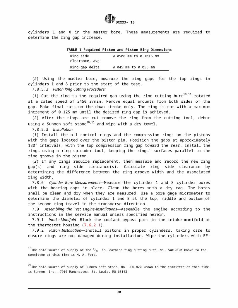
Sanford Piston Ring Grinder.18,11 Record the ring side clearance(s) and new ring gap(s) on any ring(s) adjusted. Enter the new dimension(s) on the Supplemental Operational Data sheets. Typical forms for recording these dimensions are shown in Appendix X1. Ensure that the required ring gap delta and ring side clearance are attained (Table 1). Replace rings if smaller ring gaps are required. Measure the rings for cylinders 1 and 8 in the master bore. These measurements are required to determine the ring gap increase.
TABLE 1 Required Piston and Piston Ring DimensionsRing side clearance, avg 0.0508 mm to 0.1016 mmRing gap delta 0.045 mm to 0.055 mm
(2) Using the master bore, measure the ring gaps for the top rings in cylinders 1 and 8 prior to the start of the test.7.8.5.2 Piston Ring Cutting Procedure: (1) Cut the ring to the required gap using the ring cutting burr19,11 rotated at a rated speed of 3450 r/min. Remove
equal amounts from both sides of the gap. Make final cuts on the down stroke only. The ring is cut with a maximum increment of 0.125 mm until the desired ring gap is achieved.
(2) After the rings are cut remove the ring from the cutting tool, debur using a Sunnen soft stone20,11 and wipe with a dry towel.
7.8.5.3 Installation:(1) Install the oil control rings and the compression rings on the pistons with the gaps located over the piston pin.
Position the gaps at approximately 180° intervals, with the top compression ring gap toward the rear. Install the rings using a ring spreader tool, keeping the rings' surfaces parallel to the ring groove in the piston.
(2) If any rings require replacement, then measure and record the new ring gap(s) and ring side clearance(s). Calculate ring side clearance by determining the difference between the ring groove width and the associated ring width.
7.8.6 Cylinder Bore Measurements—Measure the cylinder 1 and 8 cylinder bores with the bearing caps in place. Clean the bores with a dry rag. The bores shall be clean and dry when they are measured. Use a bore gage micrometer to determine the diameter of cylinder 1 and 8 at the top, middle and bottom of the second ring travel in the transverse direction.
7.9 Assembling the Test Engine-Installations—Assemble the engine according to the instructions in the service manual unless specified herein.
7.9.1 Intake Manifold—Block the coolant bypass port in the intake manifold at the thermostat housing (7.6.2.1).7.9.2 Piston Installation—Install pistons in proper cylinders, taking care to ensure rings are not damaged during
installation. Wipe the cylinders with EF-411. Install the pistons and connecting rods with the notches facing the rear. Install the rod bearing caps and torque to 40 N·m to 45 N·m with an additional 90° rotation.
7.9.3 Oil System Components—All oil system components in the engine are production configuration with the exception of the oil pan that contains removable baffles.
7.9.4 Cylinder Head Installation—Cylinder heads are obtained from the supplier in A13.2. Heads may be used for multiple tests, as long as they remain serviceable.
18The sole source of supply of the 3/16 in. carbide ring cutting burr, No. 74010020 known to the committee at this time is M. A. Ford.
19The sole source of supply of Sunnen soft stone, No. JHU-820 known to the committee at this time is Sunnen, Inc., 7910 Manchester, St. Louis, MO 63143.
20The sole source of supply of Pencool 2000 coolant known to the committee at this time is Penray Cos., Inc., 1801 Estes Ave., Elk Grove, IL 60007.
15
DXXXX– 15
(1) Disassemble heads and inspect for any debris or other deleterious materials and remove as necessary.(2) If the cylinder heads have not been previously used, spray the cylinder heads with degreasing solvent (see
7.7.1). If the cylinder heads have been used previously, soak in organic solvent (see 7.7.2) for 24 h, place the cylinder heads in the dishwasher type cleaning machine (7.5.7) using soap (7.7.5) at 60 °C for 30 min. Promptly remove the cylinder head from the cleaning machine and spray with a 50/50 mixture of EF-411 and degreasing solvent (7.7.1).
(3) Determine valve guide clearance at the top and middle of the heads on the transverse side of the guide. Reject any heads that exceed (0.020 to 0.069) mm for intake and (0.046 to 0.095) mm for exhaust.
(4) Assemble the cylinder heads in accordance with the manual. Verify valves are properly seated. The method is left at the discretion of the laboratory.
(5) Install cam bearings. Camshafts can be installed at this time.7.9.4.1 Heads may also be procured from the source listed in A13.3. Modify heads from this source to accept cam
bearings, and have new valve guides installed, by the source listed in A13.5.(1) Conduct a successful reference oil test prior to using these heads for all testing.
7.9.5 Camshaft and Related Components—Install the camshaft and gears in the same manner as described in the service manual.
7.9.5.1 Prior to the timing chain installation, clock the crankshaft keyway at 315° of crankshaft angle (TDC of piston No. 1) as described in the service manual.9 Rotate the crankshaft clockwise only, when viewed from the front.
7.9.5.2 When viewed from the rear, maintain the camshaft D-slot shall at a 90° clocked position relative to the cam cover rail.
7.9.5.3 When installing the timing chains ensure that the timing marks (mentioned above) remain aligned. Install L.H. crankshaft sprocket with timing chain on the crankshaft. Drape the L.H. timing chain over camshaft sprocket. The timing chain shall hang below the tensioner dowel.
7.9.5.4 Repeat the procedure in 7.9.5.3 for the right hand timing chain. After installation, the timing chain shall hang between the chain guide and the tensioner dowel.
NOTE 2—There should be a minimum of chain slack on the tension side between the two sprockets.
7.9.6 Rocker Arm Cover and Baffle—Fasten the camshaft baffle to the rocker cover. Cut off the tabs from the rocker cover gasket and install it in the gasket groove on cover rail. Install rocker arm cover on the cylinder head and confirm that the baffle does not contact any valve train components. Using new rubber washers on the bolts, torque the bolts to 8 N·m to 12 N·m (the rubber washers are not reusable). The two rocker covers are different, ensure that the correct cover is installed on the correct head (Figs. A7.4 and A7.5).
7.9.7 Oil Pan, Baffles, and Insulation—Install front and rear oil pan baffles to the oil pan as shown in Fig. A7.7. Install front baffle first. Install the oil pan according to the procedure in the service manual. Install the oil pan insulation over the oil pan.
7.9.8 Water Pump, Water Pump Drive—Install the water pump block off plate and the crankshaft pulley according to the service manual. These are the only components needed to drive the water pump. All other production front end accessory drive components can be discarded.
7.10 Engine Installation on the Test Stand—Functions that are to be performed in a specific manner or at a specific time in the assembly process are noted.
7.10.1 Mounting the Engine on the Test Stand—Mount the engine on the test stand so that the flywheel friction face is 4.0o ± 0.5° from vertical, with the front of the engine higher than the rear. The engine mounting system should be designed to minimize engine vibration at 700 r/min to 2900 r/min. Couple the engine and Vulkan damper, if used, directly to the dynamometer through a driveshaft. The engine cannot be used to drive any external engine accessory.
7.10.2 Exhaust System and Gas Sampling Fittings:7.10.2.1 The required exhaust manifold, a typical exhaust system, and O2 sensor and thermocouple fittings are
illustrated in Figs. A7.14, A7.15, and A7.16. Exhaust components shown in Fig. A7.16 should be constructed of either solid or bellows pipe/tubing. Other type flexible pipe is not acceptable.
7.10.3 Oil Dipstick and Tube—Install modified oil dipstick and dipstick tube, described in 7.4.4, in the engine block at the production location and attachment points.
NOTE 3—The intake manifold, the rocker arm covers, and the exhaust manifolds can be installed after the engine is installed on the test stand.
7.10.4 Fuel Management System:7.10.4.1 Fuel Rail Injectors:
16
DXXXX– 15
(1) The fuel injectors can be used for multiple tests providing they meet the requirements delineated in Annex A16. Fuel injectors that have caused misfires in previous tests should be cleaned before reuse. Commercial injector cleaning fluids and flow benches are available from various manufacturers. Do not use injector cleaning fluids while operating the engine.
(2) Inspect the O-rings to ensure they are in good condition and will not allow fuel leaks. Install the fuel injectors into the fuel rail and into the intake manifold.
7.10.4.2 Electronic Engine Control (PCM) System—The fuel injector operation, cylinder firing, pulse width, ignition timing, and so forth, are controlled by the specified PCM. The PCM is available from the supplier listed in A13.8.
(1) The PCM power shall come from a battery 13.5 V ± 1.5 V or a power supply that does not interrupt/interfere with proper PCM operation. Connect the PCM battery/power supply to the engine wire harness with an appropriate gage wire of the shortest practical length so as to maintain a dc voltage of 12 V to 15 V on the STAR tester and minimize PCM electrical noise problems. Ground the PCM ground wire to the engine. From the same ground point, run a minimum two gage wire back to the battery negative to prevent interruption/interference of the PCM operation. The power supply can also be used for the Lambda measuring devices.
7.10.5 Spark Plugs—Install new Motorcraft AGSF-32-PM spark plugs that have been gapped to 1.37 mm. Torque the spark plugs to 9 N·m to 12 N·m. Install the spark plug wiring harness. Do not use anti-seize compounds on spark plug threads.
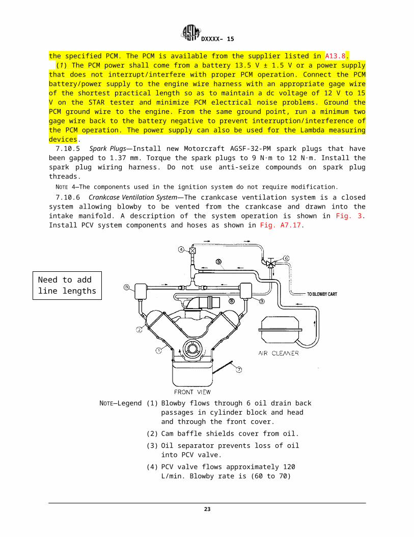
NOTE 4—The components used in the ignition system do not require modification. 7.10.6 Crankcase Ventilation System—The crankcase ventilation system is a closed system allowing blowby to
be vented from the crankcase and drawn into the intake manifold. A description of the system operation is shown in Fig. 3. Install PCV system components and hoses as shown in Fig. A7.17.
NOTE—Legend (1) Blowby flows through 6 oil drain back passages in cylinder block and head and through the front cover.
(2) Cam baffle shields cover from oil.
(3) Oil separator prevents loss of oil into PCV valve.
(4) PCV valve flows approximately 120 L/min. Blowby rate is (60 to 70) L/min.
(5) Air vent provides balance of flow by PCV valve.When excessive plugging of the PCV valve
occurs excess blowby is vented to the air cleaner.
17
Need to add line lengths
DXXXX– 15
(6) Three-way ball valve routes blowby to the intake manifold and provides a connection point for blowby measurement apparatus.
(7) Dipstick tube is location for crankcase pressure measurement.
(8) Under normal flow conditions blowby is routed to the engine air intake
FIG. 3 Functional Description of Closed Crankcase Ventilation System
7.10.6.1 Oil Separator and PCV Valve—Use two clean oil separators and a new PCV valve listed in the parts list A9.3 and A13.6. Oil separators can be disassembled, cleaned by soaking in degreasing solvent and reused as long as they remain serviceable.
7.10.6.2 Three-Way Valve—Install a clean three-way valve and attach the PCV valve hose. Install the remaining PCV valve hose between the three-way valve and the intake manifold (see Fig. 3 and Fig. A7.17). Do not allow the hose to flatten at the bend after installation.
7.10.7 Intake Air Components—Install the throttle body, throttle body spacer, fresh air tube, air cleaner assembly, and new air filter. Modify the air cleaner assembly to accept fittings for inlet air temperature thermocouple, pressure tap and fresh air, as shown in Fig. A7.1.
7.10.8 External Hose Replacement—Inspect all external hoses used on the test stand and replace any hoses that have become unserviceable. Check for internal wall separations that could cause flow restrictions. Check all connections to ensure security.
7.10.9 Wiring Harness—There are two wiring harnesses used on the test stand, an dynamometer harness that connects to the stand power and PCM and an engine harness. Obtain the dynamometer wiring harness and engine wiring harness from the supplier listed in A13.7.
8. Engine Fluids (Supply/Discharge Systems)
8.1 Intake Air—Condition the intake air to 30 oC ± 0.5 °C, 11.4 g/kg ± 0.8 g/kg humidity, and pressurized to 0.05 kPa ± 0.02 kPa.
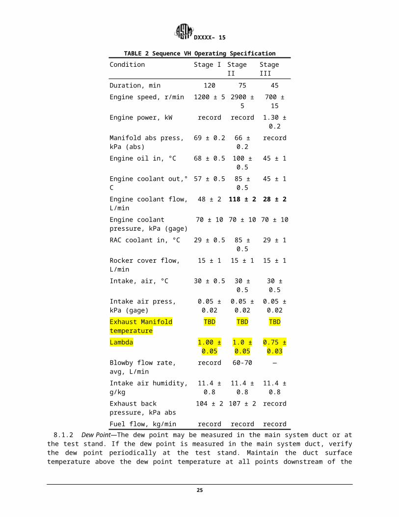
8.1.1 Capacity—The supply system shall be capable of delivering 110 L/s of conditioned air, while maintaining the intake/air parameters detailed in Table 2. The test stand intake air duct system is shown in Fig. 2.
TABLE 2 Sequence VH Operating SpecificationCondition Stage I Stage II Stage III
Duration, min 120 75 45Engine speed, r/min 1200 ± 5 2900 ± 5 700 ± 15Engine power, kW record record 1.30 ± 0.2Manifold abs press, kPa (abs) 69 ± 0.2 66 ± 0.2 recordEngine oil in, °C 68 ± 0.5 100 ± 0.5 45 ± 1Engine coolant out,° C 57 ± 0.5 85 ± 0.5 45 ± 1Engine coolant flow, L/min 48 ± 2 118 ± 2 28 ± 2Engine coolant pressure, kPa (gage)
70 ± 10 70 ± 10 70 ± 10
RAC coolant in, °C 29 ± 0.5 85 ± 0.5 29 ± 1Rocker cover flow, L/min 15 ± 1 15 ± 1 15 ± 1Intake, air, °C 30 ± 0.5 30 ± 0.5 30 ± 0.5Intake air press, kPa (gage) 0.05 ± 0.02 0.05 ± 0.02 0.05 ± 0.02Exhaust Manifold temperature TBD TBD TBDLambda 1.00 ± 0.05 1.0 ± 0.05 0.75 ± 0.03
18
DXXXX– 15
Blowby flow rate, avg, L/min record 60-70 —Intake air humidity, g/kg 11.4 ± 0.8 11.4 ± 0.8 11.4 ± 0.8Exhaust back pressure, kPa abs 104 ± 2 107 ± 2 recordFuel flow, kg/min record record record
8.1.2 Dew Point—The dew point may be measured in the main system duct or at the test stand. If the dew point is measured in the main system duct, verify the dew point periodically at the test stand. Maintain the duct surface temperature above the dew point temperature at all points downstream of the humidity measurement point to prevent condensation and loss of humidity level.
8.2 Fuel and Fuel System:8.2.1 System Description—A schematic diagram of a non-return fuel supply system is shown in Fig. 1. Deliver the fuel to a high-pressure pump (Ford P/N E7TF-9C407 or E7TC-9C407), that boosts the pressure and supplies the fuel to the fuel rail. Provide a cooling loop for the fuel as shown. Regulate the fuel pressure at the fuel rail using a Paxton regulator or equivalent. Maintain a pressure of 250 kPa ± 20 kpa at the rail. This is a non-return fuel system, the fuel rail is supplied the required fuel and pressure using the 3-way Paxton regulator. The excess fuel leaves the regulator and is cooled in the re-circulating loop shown in Fig 1. The excess fuel is mixed with the incoming fuel before the pump but after the fuel meter. The heat exchanger provides a consistent temperature at the rail.
8.2.2 Controls—Maintain the fuel temperature to the fuel rail below 50 °C. To ensure good atomization of the fuel, maintain the fuel pressure to the fuel rail above 185 kPa. In addition, the fuel pressure should be constant at all steady-state conditions to ensure good speed, power, and air-fuel ratio control.
8.2.3 Fuel Volume Required—Approximately 3300 L of sequence VH unleaded gasoline are required for each test.
8.2.4 Fuel Batch Approval Process—Obtain fuel from the supplier listed in X2.1.5. Each new batch of fuel is approved by the following process:
8.2.4.1 Before initial blending, typical samples of the fuel blend components are analyzed, and the data are compared with predetermined physical specifications. A small amount of fuel mixture is then blended, analyzed, and compared to predetermined specifications. The ASTM Sequence V Surveillance Panel (SP) confirms the acceptability of the fuel mixture analytical data and authorizes blending of the entire batch for engine testing. After the entire batch is blended, the SP confirms the acceptability of the analytical data of the entire fuel batch, and authorizes the engine test fuel approval program.
8.2.4.2 A sample of the fuel is shipped to the designated laboratories. A statistically designed test program involving more than one calibration test is completed using reference oils selected by the SP. (The Sequence V Surveillance Panel designs the test program.) The SP reviews the test results and if acceptable, authorizes the fuel supplier to notify potential purchasers of the approval status of the fuel batch.
8.2.4.3 Add fuel from a new batch to a laboratory’s fuel tank when the current fuel level is below 10 % of the final fuel (new and previous) mixture’s total volume.
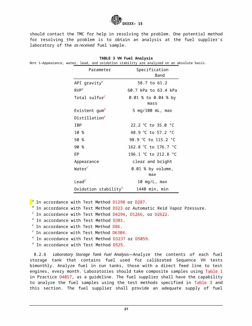
8.2.5 Fuel Batch Analysis—Upon receipt from the supplier, it is the responsibility of the laboratory to analyze each fuel shipment to determine the value of the parameters shown in Table 3 (except sulfur, oxidation stability, and distillation). Compare the results to the values obtained by the supplier on that particular batch. The results should be within the specification band shown in Table 3 beside each parameter. This provides a method to determine if the fuel batch is contaminated or has aged prematurely. If any results fall outside the tolerances shown in Table 3, the laboratory should contact the TMC for help in resolving the problem. One potential method for resolving the problem is to obtain an analysis at the fuel supplier's laboratory of the as received fuel sample.
TABLE 3 VH Fuel AnalysisNOTE 1—Appearance, water, lead, and oxidation stability are analyzed on an absolute basis.
Parameter Specification Band
API gravityA 58.7 to 61.2RVPB 60.7 kPa to 63.4 kPaTotal sulfurC 0.01 % to 0.04 % by massExistent gumD 5 mg/100 mL, maxDistillationE
19
DXXXX– 15
Parameter Specification BandIBP 22.2 oC to 35.0 °C10 % 48.9 oC to 57.2 °C50 % 98.9 oC to 115.2 °C90 % 162.8 oC to 176.7 °CEP 196.1 oC to 212.8 °CAppearance clear and brightWaterF 0.01 % by volume, maxLeadG 10 mg/L, maxOxidation stabilityH 1440 min, min
A In accordance with Test Method D1298 or D287. B In accordance with Test Method D323 or Automatic Reid Vapor Pressure. C In accordance with Test Method D4294, D1266, or D2622. D In accordance with Test Method D381. E In accordance with Test Method D86. F In accordance with Test Method D6304. G In accordance with Test Method D3237 or D5059. H In accordance with Test Method D525.
8.2.6 Laboratory Storage Tank Fuel Analysis—Analyze the contents of each fuel storage tank that contains fuel used for calibrated Sequence VH tests bimonthly. Analyze fuel in run tanks, those with a direct feed line to test engines, every month. Laboratories should take composite samples using Table 1 in Practice D4057, as a guideline. The fuel supplier shall have the capability to analyze the fuel samples using the test methods specified in Table 3 and this section. The fuel supplier shall provide an adequate supply of fuel sample containers with packaging and pre-addressed return labels to each Sequence VH laboratory. Upon receipt of all fuel samples required in 8.2.6 from the laboratories, the fuel supplier shall perform the following analyses, report the results to the submitting laboratory, and tabulate the results in a database.
Reid vapor pressure (Test Method D323) Washed gums (Test Method D381)API gravity (Test Method D287 or D1298) Unwashed gums (Test Method D381)Distillation (Test Method D86)
Lead (Test Method D3237 or D5059)8.2.6.1 When results from the physical and chemical tests listed above appear to differ significantly from the
expected results, analyze a second sample, or conduct the following tests, or do both:
Hydrocarbon speciation (Test Method D2789)Oxidation stability (Test Method D525)Potential gums (Test Method D873)
8.2.6.2 The fuel supplier shall also issue a bimonthly analysis of the fuel from the main storage tank, which should represent normal aging. The analysis shall include the parameters in Table 3.
8.2.6.3 Forward the results of the analyses performed in 8.2.6 and 8.2.6.1 to the TMC for inclusion in the appropriate data base.
8.2.7 Fuel Batch Shipment and Storage—Ship the fuel in containers with the minimum allowable venting as dictated by all safety and environmental regulations, especially when shipment times are anticipated to be longer than one week. Store the fuel following all applicable safety and environmental regulations.
8.3 Engine Oil and Engine Oil System:8.3.1 Test Oil Description:
20
DXXXX– 15
8.3.1.1 The test oil sample shall be uncontaminated and representative of the lubricant formulation being evaluated.
8.3.1.2 A minimum of 7.5 L of new oil is required to complete the test. A 20 L sample of new oil is normally provided to allow for inadvertent losses.
8.3.2 System Description:8.3.2.1 Configure the oil system as shown in Fig. A7.8 to minimize stand-to-stand variations that could influence
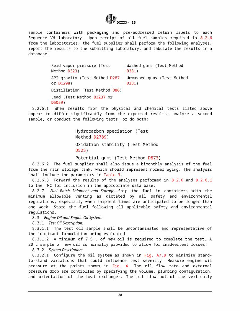
test severity. Measure engine oil pressure at the points shown in Fig. 4. The oil flow rate and external pressure drop are controlled by specifying the volume, plumbing configuration, and orientation of the heat exchanger. The oil flow out of the vertically mounted heat exchanger shall be level with the oil-in thermocouple. The lengths of the lines are not specified although the line diameters are indicated in Fig. A7.8. The line length and diameter have a large influence on the volume of the external system. The internal volume of the entire external system shall be 540 mL ± 30 mL.
FIG. 4 Oil Pressure Gage Connections
8.3.2.2 Use oil filter adapter OHT6A-0007-1 (X2.1.11), oil filter OHT6A-012-2 (X2.1.11), OHT6A-012-3 (X2.1.11) ,OHT6A-012-4 (X2.1.11) or OHT6A-012-5 (X2.1.11). Use oil filter screen OHT6A13-3 (X2.1.11). Be sure all hoses and fittings on the oil heat exchanger are properly connected and secure. The external oil system components shall not be brass, copper or galvanized, as these metals may influence used oil analysis.
8.3.3 Heat Exchanger—The heat exchanger has been chosen to minimize the volume of the external system. The
21
DXXXX– 15
heat exchanger has adequate but not excessive capacity to control the oil temperature. The system requires a high level of maintenance to provide adequate cooling, especially when process water temperature is high. An effective, well-maintained process water control system is necessary to achieve the specified oil temperatures. Use vertically mounted ITT heat exchanger P/N 5-160-02-008-002 (X2.1.9). Configure the system to allow the process water to flow through the vertical tubes and the oil through the shell. This orientation facilitates cleaning of the tubes.
TABLE 4 Test Ramping RequirementsA
Stage III to IEngine speed 1195 r/min within 5 s to 20 sManifold absolute pressure 68.8 kPa within 20 s to 80 sOil inlet temperature 67.5 °C within 8 min ± 2 minCoolant outlet temperature 56.5 °C within 6 min ± 2 minRocker arm cover inlet temperature
29 °C within 17 min
Stage I to IIEngine speed 2895 r/min within 30 s to 90 sManifold absolute pressure 66 ± 0.2 kPa within 60 s to 150 sOil inlet temperature 99.5 °C within 7 min ± 2 minCoolant outlet temperature 84.5 °C within 7 min ± 2 minRocker arm cover inlet temperature
84.5 °C within 17 min ± 2 min
Stage II to IIIEngine speed 715 r/min within 5 s to 20 sEngine power < 3 kW at 5 s to 20 sOil inlet temperature 46 °C within 15 min ± 2 minCoolant outlet temperature 46 °C within 9 min ± 2 minRocker arm cover inlet temperature
30 °C within 10 min ± 2 min
Lambda 0.705 to 0.765 at 15 sATest Ramping Requirements Information—At the start of the III to I ramp, return the mass air flow to engine control module relay to its normal position, allowing the mass air flow sensor to provide the normal signal to the engine.
8.3.4 System Cleaning:8.3.4.1 Clean the external oil cooling system thoroughly before each test. An acceptable technique for cleaning
the oil heat exchanger is detailed in Annex A10. Flush and rinse the external lines before each test. The specific technique used (removed from or flushed on the stand, and so forth) is left to the discretion of the laboratory.
8.3.4.2 Regardless of the flushing technique employed, use an organic solvent (see 7.7.2) for the final flushing followed by separate rinses with hot water (> 60 °C) and degreasing solvent (7.7.1) before air-drying the components. (Warning—Incomplete cleaning of the external oil system may allow debris to dislodge and circulate throughout the engine during subsequent tests. Incomplete cleaning may also cause oil temperature control problems and contaminate subsequent test oils.)
8.3.5 Control Specifications—The operating conditions are specified in Table 2. Additional information concerning the oil pressure, is found in 12.5.7. Cyclic ramping specifications are detailed in Table 4.
8.4 Coolants:
22
Add AFR ramp req
DXXXX– 15
8.4.1 Description—The engine coolant is equal parts of demineralized (less than 0.34 g/kg) or distilled water and a fully formulated ethylene glycol based automotive antifreeze to protect against corrosion of all system components. The RAC coolant is a solution of demineralized (less than 0.34 g/kg) or distilled water and an additive treatment of 475 mL of Pencool 2000 21,11 per 15 L of water.
8.4.2 General System Description—The following guidelines are common to both the engine and RAC coolant systems:
8.4.2.1 A transparent section is required to permit visual inspection of the coolant. Provide air bleeds to allow removal of entrained air. Provide a drain at the low point of the system to allow complete draining of the system.
8.4.2.2 An effective, well-maintained process water control system is necessary to achieve the specified coolant temperatures.
8.4.2.3 The system shall allow precise calibration of the flowmeters, after installation in the test stand. Avoid turbulence near the measurement meters, and the flowmeters used for calibration.
8.4.3 Engine Coolant System Description:
8.4.3.1 Configure the engine cooling system according to the schematic diagram shown in Fig. A7.18. The engine coolant system volume shall be 24 L ± 2 L. This volume includes all equipment, plumbing, and the engine excluding the coolant reservoir and plumbing connecting the coolant reservoir with the main system (see Fig. A7.18) The coolant reservoir volume shall be 9.0 L ± 2 L. Remove the engine water pump and install OHT plate (PN: OHT 6A 014-1). Coolant is pumped using an external pump (see A13.10). The thermostat housing is modified to accept the coolant outlet temperature thermocouple (9.1.3). Do not install the thermostat. Insert an orifice plate in the position of the thermostat (OHT PN: OHT6A-004-1). Block coolant bypass port in intake manifold (7.6.2.1). Install a coolant flow meter in the horizontal position on the inlet side of the external coolant pump. VFD [variable frequency drive] devices are acceptable in this application.
8.4.3.2 A radiator cap is used to limit system pressure to 105 kPa. Pressurize the coolant system to 70 kPa ± 10 kPa at the top of the coolant reservoir (Fig. A7.18).
8.4.3.3 The engine coolant flow rate and outlet temperature are controlled in accordance with the specifications listed in Table 2. Information concerning the cooling flow rate measurement device is detailed in 9.3.2. Cyclic ramping specifications are detailed in Table 4. The coolant flow rate is measured with a flowmeter (X2.1.6) and controlled with an in-line flow control valve.
8.4.3.4 As a minimum, inspect and clean the engine coolant system components, external to the engine, prior to running each reference calibration test. A specific flushing technique is not specified. However, the technique should employ a commercial descaling cleaner (7.7.3).
8.4.4 RAC Coolant System Description:8.4.4.1 Inspect and clean the complete RAC control system prior to running each reference oil calibration test. A
specific flushing technique is not specified. However, the technique should employ a commercial descaling cleaner (7.7.3).
8.4.4.2 Schematic diagrams of the RAC coolant control systems are shown in Fig. 5. Derive heat for the control system from an external source, such as hot water, steam, or an electric immersion heater.
21Supporting data have been filed at ASTM International Headquarters and may be obtained by requesting Research Report RR:D02-1218.
23
DXXXX– 15
Legend
(1) Vented reservoir cap(2) Coolant reservoir (fabricated)(3) Pressure control valve (optional)(4) Chilled process water control valve(5) Stage I and III heat exchanger(6) F and P Co. flowrator tube, FF-1-35-G-
10/448D053U06(7) Rocker arm covers(8) Inlet temperature sensor(9) Flow control valve(10) External heat source(11) Electric coolant pump DAYTON 6K581A(12) ABB Kent-Taylor flow element,
1330LZ08000-8375A
FIG. 5 Typical Rocker Arm Cover Heating and Cooling System
24
DXXXX– 15
8.4.4.3 Control the RAC coolant flow rate and inlet temperature in accordance with the specifications listed in Table 2. The coolant pressure is not specified, but design the system to minimize the pressure on the RAC and prevent distortion of the jacket. (Warning—Maintain the system pressure below 70 kPa to prevent distortion of the RAC jacket.)
8.5 Cyclic ramping specifications are detailed in Table 4.8.6 Closed Loop AFR Control:8.6.1 The test PCM is calibrated to control the fuel mixture to generate a lamda value of .75 during third stage and
lambda of 1.0 during stages I and II.8.6.1.1 The test bed control system must deliver a feed forward discreet signal to the PCM to indicate which
lambda value to run. The PCM will then control the fuel management in closed loop with feedback from an average signal from the left and right bank O2 sensors.
8.6.1.2 Switch the control signal accordingly from a voltage of xx to run stoichiometric in Stages 1 and 2 and a voltage of xx to run lambda = 0.75 in Stage III.
9.0 Measurement Instrumentation
9.1 Temperatures:9.1.1 Equipment:9.1.1.1 Temperature measurement locations for the six required temperatures are specified. Use thermocouples
that are calibratable to 0.5 °C. There are no temperature inputs to the PCM9.1.1.2 All thermocouples, except the intake-air thermocouple, shall be premium and sheathed. The intake-air
thermocouple may be an open-tip type. The diameter and length of the thermocouples shall be 3 mm by 100 mm. Thermocouples, wires, and extension wires should be matched to perform in accordance with the special limits of error as defined in ANSI MC96.1.
9.1.2 Engine Coolant Inlet—Install the sensor in the outlet perpendicular to the run of the tee fitting upstream from the water pump inlet (300 to 400) mm from the face of the block. Install sensor with the tip in the center of the stream of flow, directly opposite of the perpendicular outlet. (See Fig. A7.18).
9.1.3 Engine Coolant Outlet—Install the temperature sensor in the modified thermostat housing. Locate the tip of the temperature sensor in the center of the stream of flow and is located in the thermostat housing neck within 80 mm of the housing outlet.
9.1.4 Engine Oil Inlet—Install the tip of the sensor at the center of the flow stream through the external oil filter adapter (see Fig. A7.8). Tip of sensor shall be even with the machined surface of the oil filter adapter.
9.1.5 Engine Oil Outlet—Install the tip of the sensor at the center of the cross fitting attached to the bottom of the heat exchanger (see Fig. A7.8). Locate the sensor along the same axis, but opposite, the outlet port connected to the heat exchanger. The tip shall be within 2 mm of the center distance between the external most surfaces of the outlets along the axes.
9.1.6 Intake Air—Install the tip of the thermocouple midstream in the air cleaner (see Fig. A7.1). Insertion depth shall be (55 ± 2) mm.
9.1.7 RAC Coolant Inlet—Install the tip of the thermocouple at the center of the cross fitting before the inlets of the RAC's (see Fig. 5, item 8). Locate the sensor along the same axis, but opposite the inlet port of the incoming fluid. The tip shall be within 2 mm of the center distance between the external most surfaces of the outlets along the axes.
9.1.8 Exhaust Manifold Temperature – Install a thermocouple into hole provided in the exhaust manifold spacer. Insure thermocouple tip contacts the surface at the bottom on the hole to measure the temperature of the surface contacting the cylinder head.
9.1.9 Calibration—Calibrate all thermocouples prior to a reference oil test. The temperature measurement system shall indicate within ± 0.5 °C of the laboratory calibration standard. The calibration standard shall be traceable to NIST.
9.2 Pressures:9.2.1 Equipment—Pressure measurement for each of the eight required parameters is detailed in the following
sections. This allows reasonable opportunity for adaptation of existing test stand instrumentation. Replace pressure sensors that are part of the PCM system with only Ford specified equipment.
NOTE 5—Tubing between the pressure tap locations and the final pressure sensors should incorporate condensate traps, as indicated by good engineering practice. This is particularly important in applications where low air pressures are transmitted by means of lines which pass through low-lying trenches between the test stand and the instrument console.
25
DXXXX– 15
9.2.2 Intake Manifold Absolute—Measure the manifold absolute pressure at the port on the right side of the throttle body spacer (see A7.17).
9.2.3 Engine Oil—Measure oil pump pressure at the bottom port of the oil filter adapter housing on the engine block (see Fig. 4 and Fig. 7.24) Take cylinder head oil pressure measurements on the sides of the cylinder heads on the rear of the left cylinder head and front of the right cylinder head (see Fig. 4 and Fig. A7.23). Use individually dedicated pressure sensors.
9.2.4 Engine Coolant Pressure—Measure engine coolant pressure at the top of the coolant reservoir as shown in Fig. A7.18.
9.2.5 RAC Coolant—RAC coolant pressure can be measured at the coolant inlet cross fitting as is done with temperature although monitoring of RAC pressure is not required. Pressure should remain adequate as long as temperature and flow are within the limits of Table 2.
9.2.6 Fuel—Measure the fuel pressure near the injector rail inlet as shown in Fig. 1. When utilizing a pressure gage mounted directly to the injector rail, the gage should be a damped, liquid-filled type. (Warning—Too much mass attached to the fuel rail may cause it to leak. Any instrumentation attached to the fuel rail should be supported by something other than the fuel rail.)
9.2.7 Intake Air—Measure the intake-air pressure in the air cleaner housing in the location shown in Fig. A7.1. Insertion depth of the probe shall be 50 mm ± 2 mm. If a manometer is used, install a liquid trap to prevent manometer fluid from entering the intake-air cleaner.
9.2.8 Crankcase—Measure the crankcase pressure at the dipstick tube. The sensor shall be capable of measuring positive and negative pressure.
9.2.9 Exhaust Back Pressure—Measure the exhaust back pressure with the exhaust gas sampling probe located downstream in the Y (see Fig. A7.16). A sensor capable of absolute or gage measurement corrected with barometric pressure reading is recommended. Install a condensate trap between the probe and sensor to accumulate water present in the exhaust gas.
9.2.10 Calibration—Calibrate all pressure measurement sensors prior to a reference oil test. The MAP pressure measurement system shall indicate within 0.1 kPa of the laboratory calibration standard. All other pressure measurement systems shall conform to the guidelines in ASTM Research Report RR:D02-1218.22 The calibration standard shall be traceable to NIST.
9.3 Flow Rates:9.3.1 Equipment—Flow rate measurement for each of the four required parameters is detailed in the following
subsections. With the exception of the engine coolant and blowby flow rates, measurement equipment is not specified for a given parameter. This allows reasonable opportunity for adaptation of existing test stand instrumentation.
9.3.2 Engine Coolant—Determine the engine coolant flow rate by measuring with a flowmeter with an accuracy of < 0.5% (see Fig. A7.18) An example of a flowmeter meeting this accuracy is listed in X2.1.6. Take precautions to prevent air pockets from forming in the lines to the pressure sensor. Transparent lines or bleed lines, or both, are beneficial in this application. Ensure that the manufacturer’s required straight sections of pipe are installed immediately up and down stream of the flowmeter.
9.3.3 RAC Coolant—Measure the total volumetric coolant flow rate through the RAC system and the individual RAC flowrates as shown in Fig. 5.
9.3.3.1 Calibration—Calibrate the flowmeters used in the measurement of both the engine coolant flow rate and RAC coolant flow prior to a reference oil test. Calibrate the flowmeters as installed in the system at the test stand with test fluid. Calibrate the flowmeters with a turbine flowmeter or by a volume/time method at the three operating conditions. See Table 2.
9.3.4 Blowby:9.3.4.1 Measure the blowby flow rate using the apparatus shown in Fig. 6. The measurement system routes the
blowby through an external, sharp-edged orifice and into the engine intake manifold by means of an auxiliary (dummy) PCV valve. Maintain crankcase pressure during operation of the system at 0.0 Pa ± 25 Pa to minimize the potential for crankcase leakage. Mount the dummy PCV valve and orifice plate in a vertical position.
222ASTM Test Monitoring Center, 6555 Penn Avenue, Pittsburgh, PA 15206-4489. www.astmtmc.cmu.edu.
26
DXXXX– 15
Legend(1) 12.7 mm full flow stainless steel ball
valve(2) PCV valve(3) Moroso Oil separator part no. 85487(4) Surge chamber(5) Orifice meter(6) Pressure transducer(7) Crankcase pressure gage(8) Bleed valve(9) Dummy PCV valve(10) Thermometer or temperature sensor(11) Excess blowby vent pipe. (during
normal operation)
FIG. 6 Blowby Measurement Apparatus
9.3.4.2 Determine the blowby flow rate by measuring the differential pressure drop across the sharp-edged orifice; an inclined manometer or differential pressure sensor is required for measurement of the differential pressure drop. The differential pressure drop sensor shall have a range from 0 kPa to 1 kPa.
9.3.4.3 Fabricate the sharp-edged orifice assembly that is specifically designed for blowby flow rate measurement in strict compliance with the specifications that are available from the TMC. Additional information on the orifice system can be obtained from the source listed in X2.1.8 The assembly contains five orifices. The 9.525 mm orifice is generally satisfactory for the range of blowby flow rate encountered. The complete orifice assembly can also be purchased from the supplier listed in X2.1.11.
9.3.4.4 As a minimum, clean the blowby measurement apparatus weekly. Replace the o-rings with each cleaning. Exercise particular care when cleaning the orifice meter assembly. Clean the three-way valve by soaking the valve in agitated organic solvent (see 7.7.2) until clean, followed by hot (> 60 °C) water rinse and spray rinse with degreasing solvent (7.7.1). Use compressed air to force-dry. Inspect the port passages and remove any carbonaceous deposits by scraping. If the valve is disassembled for cleaning, make sure the core is properly seated upon
27
DXXXX– 15
reassembly.9.3.4.5 Calibrate the blowby orifice meters used for laboratory measurements standards every six months.
Calibrate laboratory blowby measurements standards, not used for production, yearly. The calibration standard shall be traceable to the NIST. Calibrate the temperature measuring devises in the blowby system every six months. (Warning —Internal leakage within the three-way valve may cause some of the blowby gas to pass directly to the intake manifold from the test PCV valve and result in erroneous blowby flow rate measurements (see Fig. 6).)
9.4 Fuel Consumption—Determine the fuel consumption rate by measuring the amount of make-up fuel flowing from the external fuel tank. The measurement point is upstream of the return flow from the fuel rail (see Fig. 1).
9.4.1 Calibrate mass flowmeter or gravimetric systems prior to each reference oil test. Volumetric systems shall be temperature and specific gravity compensated and calibrated against a mass flow device. The flowmeter located on the test stand shall be within 1 % of the calibration standard.
9.5 Speed and Torque:9.5.1 The dynamometer speed and torque control systems shall be capable of maintaining the limits specified in
Table 2 and meet the ramping requirements specified in Table 4. These limits require control within ± 0.9 % for operation during Stages I and II. Because the dynamometer and driveline frictional losses might approach the power produced by the engine during Stage III, manage the control input and system response during Stage III carefully to maintain engine operation within the specified tolerances. These tolerances are necessary to maintain a stable air-fuel ratio during Stage III. Hydraulic dynamometers have slow control response at low speeds and are not suitable for operation during Stage III.
9.5.2 Utilize a full closed-loop system using a dry gap dynamometer. A typical closed-loop system maintains engine speed by varying the electrical current to the dynamometer and maintains engine power by varying the engine throttle position. The total driveline inertia through to the dynamometer, excluding the engine flywheel, shall be 0.8 kg·m2 ± 0.1 kg·m2.
9.5.3 Calibrate the load cell transducer and readout system with deadweights at least once per test. Calibration of the zero scale readout is recommended once per day during the oil level soak period. Calibrate the speed measurement system prior to a reference oil test.
9.6 Exhaust Gas:9.6.1 Equipment:9.6.1.1 Determine the air-fuel ratio using a wide band O2 sensor to measure Lambda. The device shall have a
minimum accuracy of ± 0.021 of lambda. The required device is shown in A13.99.6.1.2 Calibrate, zero, and span the AFR sensor in accordance with the user's manual prior to conducting a stand
reference oil test sequence or whenever a sensor is replaced.9.6.2 Calibrate the lambda measuring device before every reference test. 9.7 Humidity:9.7.1 The intake air humidity is recorded using the laboratory's primary humidity measurement system. Make
corrections to each reading, for non-standard barometric conditions, using an additive correction derived from the perfect gas law.
9.7.2 The primary laboratory measurement system is calibrated at each stand on a semi-annual basis using a hygrometer with a minimum dew point accuracy of ± 0.55 °C at 16 °C. The calibration consists of a series of 20 paired measurements between the primary laboratory system and the calibration hygrometer (see Table 5 for an example). The measurement interval shall be appropriate for the time constant of the humidity measuring instruments and the control system. Comparison periods of 20 min to 2 h, with measurements recorded at intervals of 1 min to 6 min intervals, are typically acceptable. The measurements taken with the calibration hygrometer are corrected to standard barometric pressure (101.1 kPa) using the perfect gas law. The sample line shall be non-hygroscopic. Exercise precaution to prevent condensation of the sample.
TABLE 5 Humidity Calibration ExampleNOTE 1—Test Type-VH; Test Stand – 29; Date – 11/12/15; Barometric pressure – 29.1 in. Hg; Humidity correction – to 0.28 g/kg.NOTE 2—Humidity readings are corrected for non-standard barometric pressure.NOTE 3—X = Mean difference, g/kg – 0.2.S = Standard deviation, g/kg – 0.11.NOTE 4—If mean difference > 1.4 g/kg, calibration is invalid.NOTE 5—If standard deviation > 0.71 g/kg, calibration is invalid.
Zi Yi Yi-Zi
28
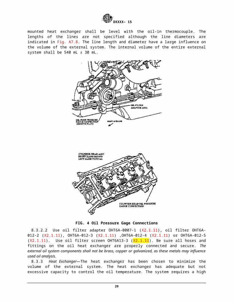
DXXXX– 15
System Calibration
Reading Humidity Humidity Difference
1 11.3 11.4 0.12 11.2 11.5 0.33 11.2 11.5 0.34 11.2 11.6 0.45 11.3 11.6 0.36 11.3 11.6 0.37 11.3 11.6 0.38 11.3 11.6 0.39 11.4 11.6 0.210 11.4 11.7 0.311 11.5 11.7 0.212 11.5 11.7 0.213 11.4 11.6 0.214 11.4 11.6 0.215 11.5 11.6 0.116 11.6 11.6 0.017 11.6 11.7 0.118 11.6 11.7 0.119 11.6 11.7 0.120 11.5 11.7 0.2
9.7.3 The difference between each pair is computed and used to form a mean and standard deviation. The absolute value of the mean difference cannot exceed 1.4 g/kg, and the standard deviation cannot exceed 0.71 g/kg. Both of these requirements shall be met to consider the primary humidity measurement system to be calibrated. If either of these requirements cannot be met, the laboratory shall investigate the cause, make repairs, and recalibrate. The calibration data is maintained for two years.
9.7.4 The calibration sample tap is located on the air line to the engine, between the main duct and entrance to the air filter housing.
10. Miscellaneous Laboratory Equipment
10.1 STAR Tester —A STAR (self test automatic readout) tester will be necessary to diagnose the PCM system in case of a malfunction or operational abnormality. Instructions on the use of the STAR tester can be found in the service manual.
10.2 Beaker—A beaker with a capacity of 5000 mL is suitable for the initial oil fill. A beaker with a capacity of 500 mL is suitable for oil additions.
11. Test Stand Calibration
11.1 Verification:11.1.1 Verify the calibration of test stands. (See A.2.2.1 for general details.) Stand calibration tests are normally
conducted upon expiration of either the 120 day calibration time period or after completing 10 non-reference oil tests. However, calibration time periods may be adjusted by the TMC. Additionally, any test terminated with 50 test hours or less will not be counted towards the 10 allowed runs. Any non-reference oil test started within 120 days of the previous calibration test is considered within the calibration period, provided the 10 allowed non-reference oil tests that have been completed since the previous calibration test in the stand are not exceeded. (Follow instructions
29
DXXXX– 15
in A2.6 and A2.6.1 for reporting the calibration test results.)11.1.2 A reference oil sample of 22.4 L is provided by the TMC (see A2.5 for additional information) for each
stand calibration test.11.2 Unacceptable Calibration Results:11.2.1 It is recognized that a certain percentage of calibration tests fall outside the acceptance limits because of
the application of statistics in the development of the acceptance limits. Failure of a reference oil test to meet Shewhart or EWMA precision control chart limits can be indicative of a false alarm or a stand, laboratory, or industry problem. When this occurs, the laboratory, in conjunction with the TMC shall attempt to determine the problem source. The TMC may solicit input from industry expertise (other testing laboratories, the test sponsor, ASTM Technical Guidance Committee, Sequence V Surveillance Panel, Sequence V Operation and Hardware Subpanel, and so on) to help determine the cause and extent of a problem. The Sequence V Surveillance Panel adjudicates industry problems.
11.2.2 If the TMC determines the problem is a false alarm and is stand-related, there is no impact on other non-reference tests running in other stands within the laboratory. If the TMC determines the problem is laboratory-related, non-reference tests run during the problem period shall be considered invalid, unless there is specific evidence to the contrary for each individual test.
11.2.3 The TMC reschedules a calibration test once it is satisfied that no particular problem exists or the problem has been resolved. The laboratory shall provide adequate documentation to support conclusions reached during this process. Attach this documentation to the acceptable calibration test report. It shall provide sufficient information to show how the problem related to other tests operated during the same period.
11.3 Test Stand Modifications—Report modification of test stand control systems or completion of any nonstandard test on a calibrated stand to the TMC immediately. A nonstandard test includes any test completed under a modified procedure requiring hardware or controller modifications to the test stand. The TMC determines whether another calibration test is necessary after the modifications have been completed.
11.3.1 See A.2.2 for related information about non-standard tests. 11.4 Reference Oil Accountability:11.4.1 Laboratories conducting calibration tests are required to provide a full accounting of the identification and
quantities of all reference oils used. (See A2.3 for related information.)11.4.2 With the exception of new oil analysis required in 13.6, perform no physical or chemical analysis of new
reference oils without the permission of the TMC. (See A2.4 for additional information) Retain engine parts from reference oil tests for six months.
11.5 Test Numbering System:11.5.1 Acceptable Tests—The test number shall follow the format AAA-BB-CCC. AAA represents the test stand
number. BB represents the number of tests since last reference. CCC represents the total number of tests on the stand. As an example, 6-10-175 represents the 175 test on Stand 6 and the tenth test since the last reference. Consecutively number all tests on a given stand.
11.5.2 Unacceptable or Aborted Tests—If a calibration test is aborted or the results are outside the acceptance limits, the CCC portion of the test number for subsequent calibration test(s) shall include a letter suffix. Begin the suffix with the letter A and continue alphabetically until a calibration test is completed within the acceptance limits. For example, if three consecutive unacceptable calibration test are completed on the same test stand, and the test stand number of the first test is 6-0-175, the next two test numbers would be 6-0-175A and 6-0-175B. If the results of the next calibration test are acceptable, the test number 6-0-175C would permanently identify the test and appear on future correspondence. The completion of any amount of operational time on tests other than calibration tests will cause the test number to increase by one. Add no letter suffix to the test number of tests other than calibration tests.
12. Test Procedure
12.1 Pre-test Procedure:12.1.1 Engine Break-In Procedure—Run break-in schedule listed in Table 6. Conduct the break-in before each
test using the test oil.TABLE 6 Sequence VH Break-in Schedule
Oil Leveling
Step
Condition 1 2 3
30
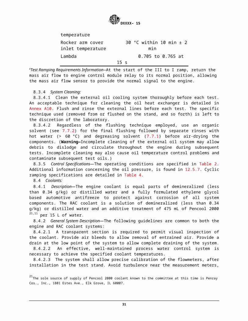
DXXXX– 15
Duration, min 2, minimum 5 40 45Total time, h:min 0:05 0:45 1:30
Engine speed, r/min 1500 ± 25 700 ± 15 2900 ± 5 700 ± 15Engine power, kW 1.30 ± 0.2 record 1.30 ± 0.2
Manifold abs press, kPa (abs) 37.6 66 ± 0.2 record
Engine oil in, °C 80 ± 2 100 ± 0.2 45 ± 1
Engine coolant out, °C 90 ± 2 85 ± 0.2 45 ± 1
Engine coolant flow, L/min 48 + 2 28 + 2 117 + 2 28 + 2
RAC coolant in, °C 85 ± 0.2 29 ± 1
Lambda 1.0 0.75
Exhaust back pressure, kPa (abs)
Speed, power and MAP ramps
Oil leveling – 20 s ramp fr/idle
Step 1 to 2 – 60 s ramp
Step 2 to 3 – 15 s ramp
12.1.1.1 Charge the engine with 3000 g of test oil before the break-in run. Run the engine at 1500 r/min ± 25 r/min and 37.6 kPa MAP until the oil temperature reaches 80 oC ± 2 °C or for at least 2 min. Record the dipstick level 20 min ± 2 min after shutdown. This shall be the Test Full mark for this test. Use the table in Annex A12 to determine the oil level.
12.1.1.2 The laboratory ambient atmosphere shall be reasonably free of contaminants. The temperature and humidity levels of the operating area are not specified. Divert air from fans or ventilation systems away from the test engine.
12.1.1.3 The break-in allows an opportunity to check PCM system operation, blowby levels, Lambda for Stage II and III, check for leaks in the various systems and purge air from the cooling systems. Specifications concerning the break-in procedure are shown in Table 6. The engine start-up and shutdown procedures are detailed in 12.2.1 and 12.2.2 respectively.
12.1.1.4 During Step 1, bleed the air from the engine and RAC coolant systems and check all fluid systems for leaks.
12.1.1.5 During Step 2, check blowby level for the Stage II conditions. A high or low blowby flow rate at this time could be indicative of the blowby flow rate during the test. A ring gap adjustment can be performed at this time or after the break-in, but within the first 48 h of the test, to achieve an adequate blowby flow rate. Testing has shown that a blowby range of (65 to 75) L/min during the break-in typically produces acceptable blowby during the test. However, the need for a ring gap adjustment is at the laboratory's discretion, noting that a ring gap adjustment cannot be made at any other time during the test.
12.1.1.6 During Step 3 (see Table 6) check the operation of the idle load control system and PCM system operation. Allow the oil and coolant temperatures to reach 45 oC ± 0.5 °C. Lambda values shall match the values listed in Table 6. If not, check the idle load circuit and the PCM system operation with a STAR tester.
12.1.1.7 Record all normal parameters in Steps 2 and 3 after operation at each step for 35 min. (Warning—Prolonged operation at a rich air-fuel ratio can cause excessive fuel dilution and alter test severity.)
NOTE 6—The engine normally requires approximately 20 min to reach steady-state conditions after a step change.12.1.1.8 Check and record oil level after break-in. If piston rings are regapped or replaced during or after the
break-in, ensure that the oil level is brought back to the last known oil level by adding new oil or removing oil.12.2 Engine Operating Procedure:12.2.1 Engine Start-up—Use the following detailed procedure each time the engine is started.12.2.1.1 Turn on the ignition, safety circuits, fuel management system, fuel pump, and the rocker arm cover
coolant pump.
31
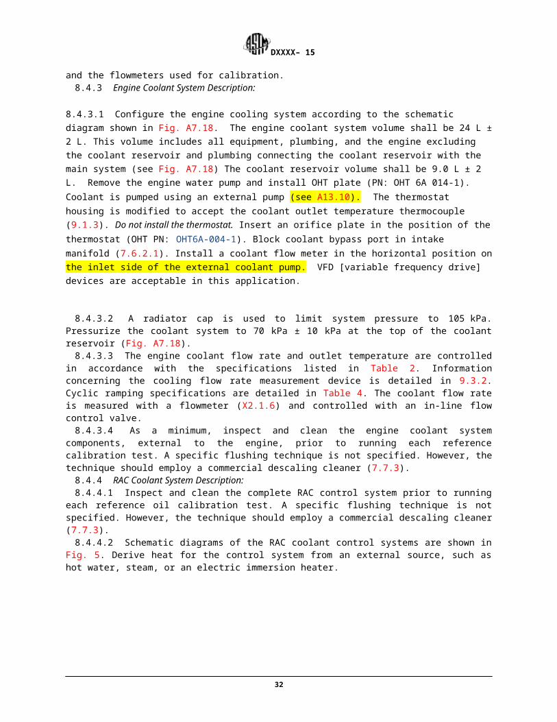
DXXXX– 15
12.2.1.2 Connect the intake-air supply duct.12.2.1.3 Crank The Engine—The engine should start within 4 s. Since the engine has a crankshaft driven oil
pump, cranking oil pressure might be low. If used, disable a low oil pressure ignition shutoff during engine starting to allow the engine to start even though the oil pressure is low. The inclusion of this type switch could lead to excessive cranking time to start the engine.
12.2.1.4 If starting difficulties are encountered, the laboratory should not continue to crank the engine excessively. Perform diagnostics to determine the reason the engine will not start (ignition problems, insufficient or excess fuel, and so forth). (Warning— Excessive cranking times can promote additional fuel dilution of the test oil and can adversely affect the test. In addition to other precautions, do not attempt to pour gasoline into the intake-air horn.)
12.2.2 Engine Shutdown:12.2.2.1 Scheduled Shutdown Procedure—Follow the procedure detailed as follows, each time a scheduled
shutdown is performed. Scheduled shutdowns include shutdowns that occur during engine break-in and oil leveling: (1) Bring the engine speed to 700 r/min ± 50 r/min and coolant flow to 28 L/min ± 2 L/min for 10 min.(2) Switch the ignition off. (Turn off power to the PCM and ignition, maintain power to the keep alive memory
(KAM).)(3) Turn off fuel and coolant pumps.(4) Reduce the intake-air pressure to atmospheric.12.2.2.2 Unscheduled Engine Shutdown—Follow the procedure detailed as follows, each time an unscheduled
engine shutdown is performed: (1) Stop test timer when ramp down starts.(2) Ramp to Stage 3: From Stage 1—15 s speed and load setpoint ramp; 6 min setpoint ramp of other controlled parameters. From Stage 2—Perform Stage 2 to 3 ramp (Table 4).NOTE 7—Total cooldown time is 6 min after the initiation of the ramp to Stage 3 conditions.(3) Switch the ignition and RAC coolant pump off (turn off power to the PCM and ignition, maintain power to the
KAM).(4) Turn off fuel and coolant pumps.(5) Reduce the intake-air pressure to atmospheric.12.2.2.3 Start-Up After Unscheduled Shutdown—Follow the procedure detailed as follows, each time an engine
start-up is performed after an unscheduled shutdown. (1) Start—5 min in Stage 3, then to: Return to Stage 1—Stage 3 to 1 ramp (Table 4). Return to Stage 2—60 s speed and load setpoint ramp; 10 min setpoint ramp of other controlled parameters.NOTE 8—Test time resumes after all controlled parameters are within specification12.2.2.4 Start-Up After Oil Leveling Period—Follow the procedure detailed as follows, each time an engine start-
up is performed after an oil leveling period. (1) Start—5 min in Stage 3; then Stage 3 to 1 ramp (Table 4).12.2.3 Cyclic Schedule, General Description:12.2.3.1 The test is composed of three stages as shown in Table 2. Together, the three stages comprise one cycle.
Each cycle lasts 4 h and is repeated 54 times for a total of 216 h. Six consecutive cycles are completed each 24 h period. Every sixth cycle is modified to provide time for oil sampling and leveling. This modification is described in 12.3.1.
12.2.3.2 Ramping requirements specifying parameter change rates are shown in Table 4. The rate of speed, temperature, fuelling and load changes, as well as the amount of enrichment between stages, can influence sludge severity and engine component wear. Therefore, ramping rates are very important.
12.2.4 Unscheduled Downtime—The oil leveling periods of 30 min are the only scheduled shutdowns allowed during the test and are counted as test time. However, the test can be interrupted to perform necessary maintenance (see 12.3.5). Note all unscheduled downtime on the Supplemental Operational Data Form of the final test report.
12.2.5 Resumption of Test Time After Unscheduled Shutdown—After an unscheduled shutdown, test time does not begin until the engine has reached operating conditions for the stage at which the shutdown occurred.
12.3 Periodic Measurements and Functions:12.3.1 Blowby Flow Rate Measurement—Every sixth cycle, measure and record the blowby flow rate at 30 min ±
5 min into Stage II. The engine shall be stable and operating at normal Stage II operating conditions. Measure blowby when the gas temperature is at least 32 °C. Blowby gas temperature shall not differ from the laboratory
32
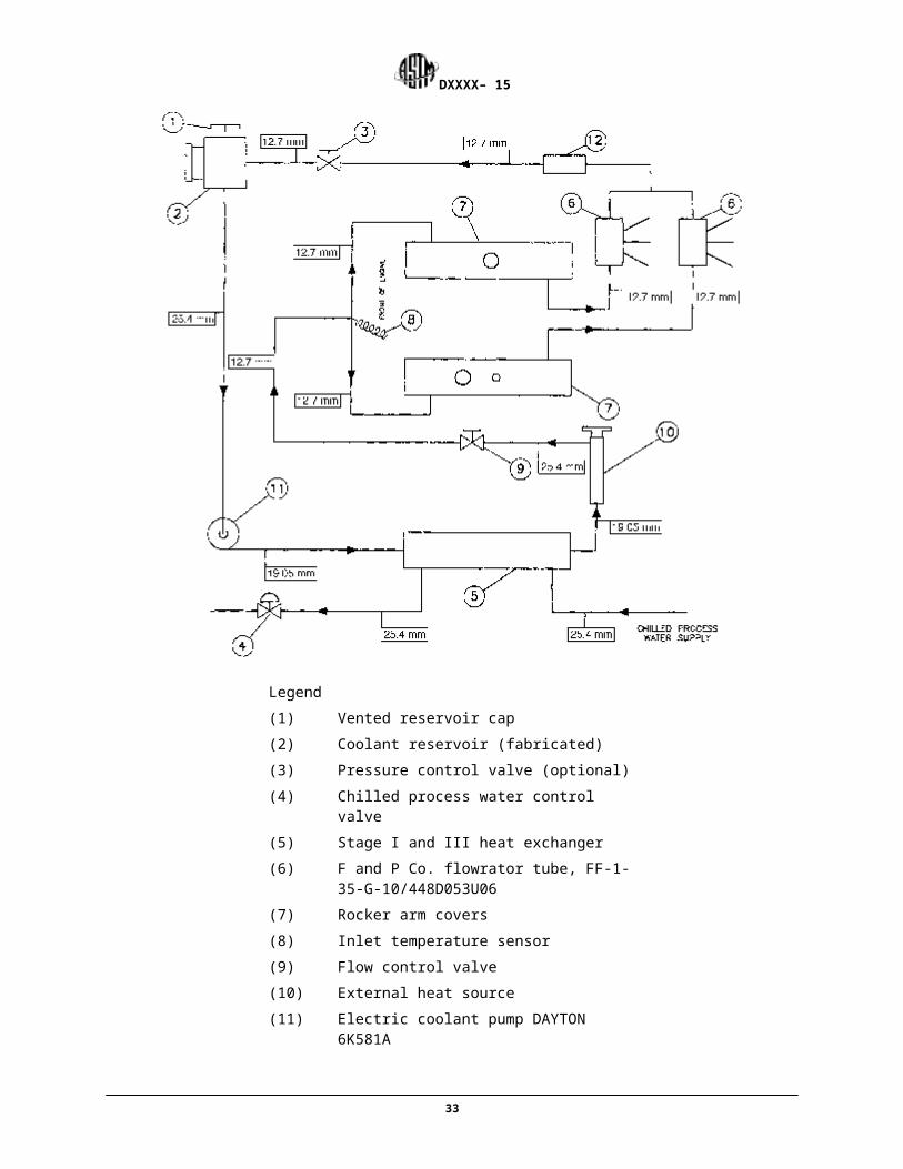
DXXXX– 15
average by more than ± 5 °C. The installation of the blowby flow rate measurement apparatus is shown in Fig. 6. The procedure for measuring blowby flow rate is detailed in 12.3.1.1. Complete only one set (Stage II) of blowby flow rate measurement during each six cycles. Under special circumstances additional blowby flow rate measurements can be performed to determine or verify a problem with the flow rate measurement apparatus or the engine. Record additional blowby flow rate measurements and an explanation of the reason for the additional measurements. Include these data in the supplemental operational data in the final test report.
12.3.1.1 Measurement Procedure:(1) Connect the apparatus pressure sensor to the dipstick tube.(2) Open the bleeder valve completely.(3) Connect the bleeder line to the three-way valve.(4) Position the three-way valve to divert intake manifold vacuum from the engine PCV valve to the dummy PCV
valve in the blowby measurement apparatus.(5) Connect the hose from the blowby meter surge chamber to the 15.9 mm inside-diameter air vent hose on the
air cleaner.(6) Adjust the bleeder valve to maintain crankcase pressure at 0 Pa ± 25 Pa.(7) Record the differential pressure, blowby gas temperature, and the barometric pressure.(8) Disconnect the apparatus pressure sensor and reconnect the engine crankcase pressure sensor to the dipstick
tube.(9) Disconnect the surge chamber hose from the air vent hose.(10) Position the three-way valve to divert intake manifold vacuum to the engine PCV valve and disconnect the
bleeder line from the three-way valve.(11) Connect the air vent hose to the intake-air cleaner.(12) Calculate the blowby flow rate and correct the value to 38 °C and 100 kPa using the calibration data for the
orifice. corrected blowby flowrate = blowby flowrate × (3.100(P/273.15+T))0.5
where:P = baro-pressure, kPa, andT = gas temperature, °C.
12.3.2 Ignition Timing Measurement—Ignition timing is set by the PCM and can only be checked with a STAR tester. Ignition timing need only be checked if improper PCM and ignition operation is suspected.
12.3.3 Exhaust Gas Analysis:12.3.3.1 The recorded readings for exhaust gas Lambda are taken during each stage and each cycle and shall be
measured immediately after the engine oil and coolant temperatures have reached steady-state conditions (approximately 20 min ± 5 min into each stage). The data are used to confirm that the PCM system is operating the engine at the correct air/fuel ratio.
12.3.4 Oil Additions and Used Oil Sampling:12.3.4.1 Oil Leveling and Sampling Procedure—Make-up oil additions for leveling and oil sampling occur at
intervals of 24 h. Annex A14 shows the cycle when this is to occur. Used oil additions are permitted only during engine reassembly for maintenance (see 12.4.2.2). Add new oil to the engine only when the level is below the original test full level by more than 400 g. Add only enough new oil to reach the low mark of 400 g. No other new oil additions are permitted during the test, except after piston ring gap adjustment (see 12.1.1.8). In the event that the oil level is above the test full mark, do not remove oil until the level is above the test full mark by more than 200 g. If more than 200 g above the test full mark drain off a sufficient amount of oil so that the level is at the 200 g above test full mark. Record the amount drained on the oil leveling sheet. The procedure is shown on the Oil Sampling, Addition and Leveling Worksheet in Annex A14. This form serves as the oil sampling and oil addition data sheet.
(1) Remove a 150 mL purge sample within first 10 min of Stage III.(2) Remove a 60 mL analysis sample within first 10 min of Stage III.(3) Return the purge sample to the engine.(4) Shut-down the engine 10 min after the start of Stage III. Turn off fuel pump and coolant pump. Do not shut off
the RAC coolant pump.(5) Record the dipstick level in millimetres 20 min ± 2 min after the engine is shutdown.(6) Compute the oil level in grams. The difference between the oil level and the Test Full mark is oil consumed or
33

DXXXX– 15
gained. Use the chart in Annex A12 to determine the level. Do not add oil at 216 h. This allows the final drain to be used as a backup to the sample taken at 216 h.
(7) If the level is more than 400 g below the Test Full mark, record the amount of new oil added to bring the level to the mark, –400 g. However, never add more than 400 g during an oil addition.
(8) If the level is more than 200 g above the Test Full mark, record the amount of oil drained to bring the level to the mark, +200 g.
(9) Restart the engine 30 min ± 1 min after shutdown (Step 4). Allow the engine to run at Stage III conditions for 5 min ± 1 min, then resume normal operation.
12.3.5 General Maintenance—The scheduled shutdown periods of 30 min during oil leveling allow limited opportunity for engine and stand maintenance. In addition, the test can be shut down at any convenient time to perform unscheduled maintenance. However, minimize the duration of a shutdown. Report any unscheduled shutdown on the Supplemental Operational Data Sheet.
12.4 Special Maintenance Procedures—Functions that require special maintenance procedures are listed in this section. These maintenance procedures are specifically detailed because of the effect on test validity or because they require special care while being completed.
12.4.1 Blowby Flow Rate Adjustment—A blowby adjustment can only be made during the break-in or within the first 48 h of the test. Blowby might drop from the break-in level but the corrected average Stage II blowby for the test during the first 120 h of the test shall fall within the range from 60 L/min to 70 L/min. Adjust the blowby by changing the ring gaps or replacing piston rings as necessary. Ensure that the ring and piston combination in each cylinder meet the criteria in Table 1. Use the ring cutting procedure outlined in 7.8.5.2.
12.4.1.1 High Blowby Flow Rate Adjustment—Reduce high blowby flow rate by replacing the compression rings with new rings that have smaller ring gaps.
12.4.1.2 Low Blowby Flow Rate Adjustment—Increase low blowby flow rate by increasing the ring gaps of the compression rings.
12.4.2 Engine Disassembly and Reassembly for Maintenance (Before End of Test):12.4.2.1 Engine assembly and disassembly shall adhere to the procedures in 7.8 and 12.6.2, respectively12.4.2.2 When the engine is disassembled for maintenance, drain as much test oil as possible from the oil pan,
and retain the oil for installation in the engine after reassembly. Take precautions to ensure the oil is not contaminated and to ensure the deposits are not disturbed on any parts, particularly on any parts that are used to determine the final test results. The Ford 4.6 L engine contains numerous areas that hold oil after the engine is drained. All parts should be placed in or over clean drain pans to collect oil that drains off while maintenance is being performed.
12.4.2.3 During reassembly, used, drained test oil may be used to lubricate the engine parts. Do not use EF-411 oil or new test oil during engine reassembly. After the engine has been reassembled, charge the oil pan with the oil removed from the oil pan and collected from the engine parts during disassembly and maintenance. Record all new oil additions and report them in the Supplemental Operational Data.
12.5 Diagnostic Data Review—This section outlines significant characteristics of specific engine operating parameters. The parameters can directly influence the test or can be used to indicate normalcy of other parameters.
12.5.1 Manifold Absolute Pressure—Manifold absolute pressure is used in Stages I and II to control engine throttle position.
12.5.2 Engine Torque—Engine torque is not controlled in Stages I and II. It should remain relatively constant throughout a test and from test to test. Large differences in torque reading could be indicative of control or engine problems.
12.5.3 Fuel Consumption Rate—The fuel consumption rate should remain relatively constant throughout the test. Fuel consumption rate is not a specifically controlled parameter but is used as a diagnostics tool.
12.5.4 Spark Knock—Spark knock does not normally occur in the VH test. The octane rating of the fuel, ignition timing, engine speed and torque, and operating temperatures do not promote spark knock. Spark knock indicates abnormal combustion is occurring and can cause extensive engine damage. Take corrective action immediately if spark knock is noted. Errors in the measurement and control of engine torque, ignition timing, operating temperatures, and air/fuel ratio may result in spark knock.
12.5.5 Exhaust Gas Component Levels:12.5.5.1 Use the Lambda levels in the exhaust gas to determine the characteristics of combustion that occur
during the test. Use this parameter to determine the normalcy of combustion and any significant changes in combustion that occur throughout a particular test. Lambda in all three stages is controlled by the program in the Powertrain Control Module. No adjustments can be made to change the exhaust gas Lambda. If Lambda differs from what appears in Table 2, check the PCM and test cell control system. Correcting a fault in the PCM and test cell
34
DXXXX– 15
control system is the only way to achieve the correct Lambda value.12.5.6 Crankcase Pressure—Crankcase pressure is a function of blowby flow rate and PCV valve flow. High
crankcase pressure is usually caused by high blowby flow rate or a significant loss of PCV valve flow. Incorrect three-way valve plumbing or port plugging also promotes high crankcase pressure. Low or negative crankcase pressure might be caused by low blowby flow rate or a restriction of vent air to the PCV valve.
12.5.7 Oil Pressure—The oil pressure is a function of oil viscosity and operating temperature. The oil pressure should remain consistent throughout the test, unless the oil exhibits a significant change in viscosity.
12.5.8 Oil Temperature Differential—The oil temperature differential is primarily a function of oil flow rate and oil viscosity and is normally stable throughout the test. The differential can change if the oil viscosity changes significantly during the test.
12.5.9 Coolant Temperature Differential—The coolant temperature differential is primarily a function of the coolant flow rate and is normally stable throughout the test. Large variations in the differential can be caused by coolant flow rate or temperature measurement errors.
12.6 End of Test Procedure:12.6.1 Final Drain—Drain the engine coolant and RAC coolant immediately after the completion of the last test
cycle. Engine oil can be drained with the engine in or out of the engine stand. Allow the engine to stand for 6 h to 12 h in the same attitude in which it was positioned on the test stand prior to drain. This allows the oil to drain completely into the oil pan. Drain the oil from the engine.
12.6.2 Engine Disassembly—During disassembly, use extreme care not to disturb engine deposits and to ensure the original location of the parts can be identified with respect to either the cylinder number, valve location, or both.
12.6.3 Parts Layout for Rating:12.6.3.1 Arrange the following parts in the parts rating area in accordance with the layouts detailed in this
section. After the parts have been arranged, allow the parts to drain for 4 h to 8 h before rating. Do not attempt to accelerate or force the oil draining. Any fixtures can be used to support the parts as long as they orient the parts in the specified configurations.
12.6.3.2 Rocker Arm Covers—Position the RAC's vertically (upper jacket surface perpendicular to the ground) with the front of the RAC at the bottom.
12.6.3.3 Camshaft Baffles—Position the camshaft baffles vertically (top baffle surface perpendicular to the ground) with the rear of the camshaft baffle pointing down.
12.6.3.4 Cylinder Heads—Position the cylinder heads with RAC gasket surface pointing down.12.6.3.5 Front Cover—Position the front cover in the same orientation as it is installed in the engine.12.6.3.6 Oil Pan—Position the oil pan upside down, with the pan rail at a 45° angle, with sump end pointing
down.12.6.3.7 Oil Pan Baffles—Position the oil pan baffles vertically on the front edges.12.6.3.8 Oil Screen and Pickup Tube—Position the oil screen and pickup tube in the same orientation as they are
installed in the engine. The screen should be raised off of the supporting surface to allow drainage. A fixture is necessary to support the oil screen and pickup tube.
13. Interpretation of Results
13.1 Parts Rating Area-Environment :13.1.1 Ensure that the ambient atmosphere of the parts rating area is reasonably free of contaminants, and the
temperature maintained at 24 oC ± 3 °C.13.1.2 Rate all engine parts except the pistons, RAC, and cylinder block under cool white fluorescent lighting
exhibiting approximately 4100 K color temperature, a CRI of 62 and an illumination level of 3800 lx to 5400 lx. All background and adjacent surfaces shall be flat white.
13.1.3 Rate pistons and RAC's against a white background using white fluorescent bulbs and a 100 % white deflector. Maintain the illumination level between 3800 lx to 6500 lx, and measure the illumination level 355 mm from the desk top.
13.1.4 If multiple ratings are deemed necessary of a given part or parts, consensus rating may be used according to the following: The raters shall be from the same laboratory or from an outside rater if required (no Red, White, or Blue rater available at the lab). Report only one rating value, and this value shall be agreed to by the original rater involved. Document any consensus rating in the comment section of the test report.
13.1.5 All raters of Sequence VH engine parts shall attend an ASTM Light Duty Deposit Rating Workshop every 12 months ± 30 days and produce data that meet the ASTM definitions of Blue, Red, or White for varnish. If a rater is unable to meet this requirement, the rater can continue to rate Sequence VH parts during a grace period of 45 days
35
DXXXX– 15
after the completion of the workshop and can follow the procedure described in 13.1.6 to generate data that meet the ASTM definitions of Blue, Red, or White.
13.1.6 A rater who is unable to meet the requirement in 13.1.5 can schedule a visit to the TMC to generate data on ASTM Light Duty Deposit Rating Workshop parts and receive an assessment of rating performance compared to data collected at recent workshops. Visits to the TMC will be scheduled based on availability of parts.
13.1.7 The TMC selects a minimum of 24 parts from a collection of workshop parts for the rater to rate varnish. The TMC provides rating booths and lights, but the rater is responsible for providing any necessary rating aids. The TMC analyzes the data and determine if the requirement in 13.1.5 has been met. If the requirement in 13.1.5 has not been met, any time remaining in the grace period of 45 days is forfeited.
13.1.8 A second attempt to generate rating data at the TMC is permitted only after the rater receives training from an experienced industry rater. The experienced industry rater shall verify to the TMC, in writing, that the rater training has taken place. No more than two attempts are permitted between ASTM Light Duty Deposit Rating Workshops.
13.2 Sludge Ratings:13.2.1 Rate the following parts for sludge deposits: RAC (2), valve deck (2), camshaft baffle (2), timing chain
cover, oil pan, and oil pan baffle. Use the rating locations identified on the rating worksheets (see Annex A15). Determine the ratings using the techniques detailed in ASTM Deposit Rating Manual 20. Perform the sludge ratings before performing any other required ratings or measurements.
13.2.2 Average Sludge (Unweighted Average of 9 Parts):13.2.2.1 To determine the sludge rating merit for each part, use the self-weighting procedure as follows: (1) Determine the sludge depth at each of the sites shown on rating worksheets. A site is defined as a diameter
circular area of 20 mm.(2) Determine an interpolated sludge value for a designated site that exhibits more than one level of sludge depth
within this area. This value is generated by multiplying each rated value’s volume factor by the percentage of area covered, totaling these volume factor percentages, and comparing the total to the values given in Table 7 to determine the rating for the site. As an example, if a site was determined to be 50 % A and 50 % E, the calculation would be: 50 % of the average sludge depth factor for A (or 1.0), plus 50 % of the average sludge depth factor for E (or 16.0); that is: ([0.5 × 1.0 = 0.5] + [0.5 × 16.0 = 8] = 8.5), and the calculated site sludge depth would be a D. In the event that there are areas where it is apparent that deposits had been formed, but are no longer adhering to the part, the rating site is the closest point to the designated point that eliminates the voided area from the 20 mm rating area.
TABLE 7 Interpolated Average Sludge Site RatingsTotal Site Ratings Total Site Ratings
<0.125 clean ≥3.500 <6.000 C≥0.125 < 0.375 1/4 A ≥6.000 < 12.00 D≥0.375 < 0.625 1/2 A ≥12.00 < 24.00 E≥0.625 < 0.875 3/4 A ≥24.00 < 48.00 F≥0.875 < 1.250 A ≥48.00 < 96.00 G≥1.250 < 1.750 AB ≥96.00 < 192.0 H≥1.750 < 2.500 B ≥192.0 < 384.0 I≥2.500 < 3.500 BC ≥384.0 J
(3) Add the total rating checks made for each line on the appropriate worksheets. These shall equal 10 or 20, depending on the part that is rated.
(4) Multiply the total rating checks made on each line by ten or five, respectively (refer to ( 3), to obtain the percent covered by the rated sludge depth. The grand total shall equal 100 %.
(5) Convert the percent covered by the rated sludge depth at each location to a volume factor using the procedure shown in ASTM Deposit Rating Manual 20.
(6) Add the volume factors on each line to determine the total volume factor. Use ASTM Deposit Rating Manual 20 to convert the total volume factor to the sludge merit rating.
13.2.2.3 Flaky, Bubbly Sludge Deposits—Since the occurrence of flaky, bubbly sludge deposits is thought to have
36
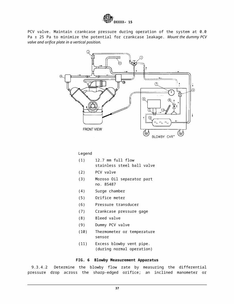
DXXXX– 15
a possible detrimental effect on long-term engine lubrication system performance, document the occurrence of this type of deposit in the Supplemental Operational Data section of the Final Test Report. Record the engine part(s) where this type of deposit was observed and the total percent of the surface area covered. The following is suggested wording–approximately 6 % of the (left or right) rocker arm cover was found to exhibit flaky, bubbly sludge deposits.
13.3 Varnish Ratings:13.3.1 Preparation of Parts—Rate the following parts for varnish deposits–piston skirts (8, thrust side only) and
left and right camshaft baffles. Perform the varnish ratings after the sludge ratings are completed. The rating locations and dimensions shall conform with the locations and dimensions detailed on the rating worksheets (see Annex A15). Avoid disturbing adjacent sludge deposits when the parts are being prepared for varnish ratings. Heavy sludge can be removed from a varnish rating area prior to wiping with a 25 mm rubber spatula. Wipe all parts firmly with wiping materials specified in ASTM Deposit Rating Manual 20. Firmly rub all wiping areas in the same direction until the surface is dry and free of sludge (until no more deposit is present on the wiping material after wiping).
13.3.2 Average Varnish (Unweighted Average of three Parts)—Use the procedure detailed as follows, to determine the varnish rating of each part:
13.3.2.1 Rate any areas where varnish deposits have been altered during disassembly or sludge removal according to deposits on the surrounding non-altered areas. Do not rate altered areas as clean.
13.3.2.2 Determine original varnish ratings of all parts by comparison of the deposit on the rating location using the ASTM Rust/Varnish/Lacquer Rating Scale for non-rubbing parts from ASTM Deposit Rating Manual 20
13.4 Clogging:13.4.1 Oil Screen Clogging:13.4.1.1 Use the following procedure to determine the percentage of the oil screen clogged by sludge: (1) Use a device to blow air across the screen to remove any retained oil on the screen. A suitable device can be
obtained from the supplier listed in X2.1.21.(2) Regulate the air pressure to 130 kPa ± 10 kPa.(3) Connect the device to the screen.(4) Allow air to flow for 5 s to 10 s.(5) Remove the device and rate.13.4.1.2 Flexible, transparent rating aids can be made for different surface areas so that when compared to the
test screen's surface, a more accurate determination of surface clogging is possible.13.4.1.3 Determine the percentage of the total screen opening that is obstructed with debris. Determine the
percentage of the total screen opening that is obstructed with sludge. Transform the oil screen sludge results by taking the natural log (ln) of the oil screen sludge rating plus one; that is, ln (oil screen clogging + one). Round the transformed value to four decimal places. Report both transformed and original result on the appropriate form(s). Label as sludge all matter present on the oil screen that is not immediately recognizable as debris. Label all matter of indeterminate composition as sludge.
13.5 Sticking:13.5.1 Compression Rings—Record the number of stuck compression rings. Definitions to classify the degree and
type of sticking are detailed in 3.1.4 and 3.1.7. List both hot and cold stuck compression rings on the Test Results Summary page. Denote hot or cold stuck rings on the Supplemental Operational Data page and include the ring location (top or second) and the piston number.
13.6 Used Oil Analyses:13.6.1 Perform the following analyses on the used oil samples taken every 24 h and on the final drain: Viscosity
at 40 °C (Test Method D445), wear metals (Test Method D5185), and fuel dilution (Test Method D3525). Take samples at (0, 24, 48, 72, 96, 120, 144, 168, 192, 216) h.
13.6.2 Fuel Dilution—Determine the fuel dilution, mass percent, by gas chromatography (see Test Method D3525, with the following modifications) on the used oil samples.
13.6.2.1 Use C16 in place of C14 for the internal standard (1μL injector volume).13.6.2.2 Presume that all components lighter than C16 are fuel.13.6.2.3 The integrator should establish a horizontal baseline under the output curve until the leading edge of C16
is reached. Establish a second baseline extending horizontally from the output curve, at the intersection of the output curve, and the leading edge of the C16 peak.
13.6.2.4 Column details are 3050 mm by 3.2 mm SS; and the packing material is 5 % OV-1 on Chromosorb W HP.
37
DXXXX– 15
13.6.2.5 Increase the oven temperature from 60 oC to 320 °C, with the rate of change of temperature controlled at 8 °C/min. Hold the temperature at 320 °C for 16 min to elute oil.
14. Assessment of Test Validity
14.1 General—The testing laboratory shall assess the validity of tests that have deviations from the procedure. The TMC and Test Sponsor shall assist the laboratory in the determination of calibration test validity, if requested by the laboratory. Use the following guidelines as a basis for determining test validity:
14.2 Used Oil Analyses-Interpretation :14.2.1 Iron and Aluminum Content—The aluminum and iron content of the used oil samples can indicate the
level of wear that occurs during a test. Increased camshaft bearing wear causes the aluminum content to increase. Increased camshaft, rocker arm, and cylinder bore wear causes the iron content to increase. The rate of change in iron levels indicates the rate of change of wear levels, although wear tends to be linear throughout the test.
14.2.2 Silicon Content—Silicon content indicates the level of contamination of the oil from external sources and silicone-based gaskets. Silicone-based gaskets are used to seal the oil pan and rocker covers. Investigate the presence of silicone-based sealers, the cleanliness of engine parts during build-up, the cleanliness of the intake air, and the cleanliness of containers used for dispensing and sampling the oil if high levels of silicon are experienced.
14.2.3 Fuel Dilution—Fuel dilution indicates the degree to which the crankcase oil has been diluted with fuel. Fuel dilution of the crankcase oil is necessary to achieve adequate test severity. However, excessive fuel dilution can promote increased sludge severity and component wear. Investigate a higher level of fuel dilution than is normally noted.
14.3 Blowby Flow Rate—The corrected average blowby flow rate during Stage II during the first 120 h of the test shall fall within the range from 60 L/min to 70 L/min. Blowby should remain relatively constant throughout the entire test. Blowby typically drops slightly in the first 23 h of the test. Excursions below 60 L/min are acceptable as long as the average is between 60 L/min and 70 L/min. If two consecutive Stage II readings within the first 120 h, are less than 56 L/min or the average is not within the prescribed limits, consider the test operationally invalid.
14.4 Manifold Absolute Pressure (MAP)—Throttle position is set by manifold absolute pressure during Stage I and II to account for the altitude of the laboratory, ambient barometric pressure, and the mechanical efficiency of the engine.
14.5 Fuel Consumption Rate—The fuel consumption rate should not exceed (9.0, 19.0, 5.0) kg/h for Stages I, II and III, respectively.
14.6 Oil Consumption:14.6.1 Oil consumption should not occur early in the test. During this time period of the test, fuel dilution levels
may increase oil levels above the test full mark. If the oil level is above the test full mark by 200 g or more, then the engine, PCM system, fuel injectors, and so forth should be checked for a malfunction that could be causing excessive fuel dilution.
14.6.2 The total amount of new oil added during the test shall not exceed 2000 g and no more than 400 g can be added at any 24 h oil leveling period.
14.7 Engine Parts Replacement—Parts that are rated to determine the final test results cannot be replaced during the test. The following parts can be replaced, if necessary (record the circumstances involved in the replacement): ignition system components, PCM system and EPROM chip, PCV valve, seals and gaskets, valves or valve springs, fuel injectors, oil separator (PCV system), and spark plugs.
14.8 Quality Index—Requirements for quality index are listed in Annex A6. If the end of test quality index value is below 0.000 for reference oil tests, review the test operations with the TMC. The TMC issues a letter to the laboratory and the test purchaser on its opinion. The laboratory documents its comments regarding end of test quality index values less than 0.000 for non-reference oil tests. The laboratory or test purchaser might request TMC review of test operations for non-reference oil tests. The TMC issues a letter to document its opinion. If a test has greater than 2 h without recorded operational data on any controlled parameter, the test is operationally invalid.
14.9 Report results on all reference oil tests run to completion, regardless of validity.
15. Final Test Report
15.1 Report Forms—For reference oil tests, the standardized report form set and data dictionary for reporting test results and for summarizing the operational data are required.
16. Precision and Bias
38
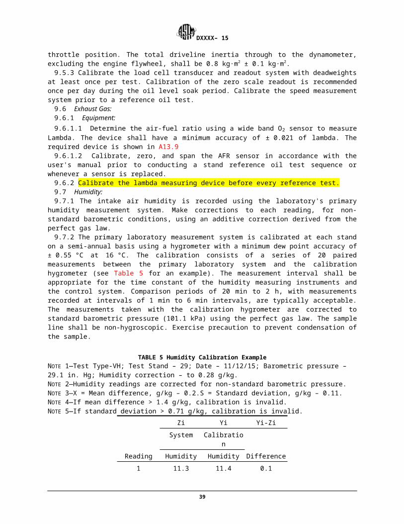
DXXXX– 15
16.1 Test Precision—Reference Oils:16.1.1 Intermediate Precision Conditions—Conditions where test results are obtained with the same test method
using the same test oil, with changing conditions such as operators, measuring equipment, test stands, test engines, and time.
NOTE 9—“Intermediate precision” is the appropriate term for this test method rather than “repeatability,” which defines more rigorous within-laboratory conditions.
16.1.1.1 Intermediate Precision Limit (i.p.)—The difference between two results obtained under intermediate precision conditions that would, in the long run, in the normal and correct conduct of the test method, exceed the values shown in Table 8 in only one case in twenty.
TABLE 8 Reference Oil StatisticsA
Intermediate Precision Reproducibility
Variable, Merits Si.p. i.p.B SR RB
Average engine sludge To Be determinedRocker cover sludgeAverage engine varnishOil screen clogging, sludgeC
Average piston varnish
A These statistics are based on results obtained on Test Monitoring Center Reference Oils over the period from through. B This value is obtained by multiplying the standard deviation by 2.8. C This parameter is transformed using 1n(result+1). When comparing two test results on this parameter, first apply this transformation to each test result. Compare the absolute difference between the transformed results with the appropriate (intermediate precision or reproducibility) precision limit.
16.1.2 Reproducibility Conditions—Conditions where test results are obtained with the same test method using the same test oil in different laboratories with different operators using different equipment.
16.1.2.1 Reproducibility Limit (R)—The difference between two results obtained under reproducibility conditions that would, in the long run, in the normal and correct conduct of the test method, exceed the values in Table 7 in only one case in twenty.
16.2 Bias—Bias will be determined by applying an accepted statistical technique to reference oil test results, and when a significant bias is determined, a severity adjustment will be permitted for non-reference oil test results.
17. Keywords
17.1 lubricating oils; Sequence VH; sludge and varnish; spark-ignition automotive engine; stop-and-go service
ANNEXES
(Mandatory Information)
A1. ASTM TEST MONITORING CENTER ORGANIZATION
A1.1 Nature and Functions of the ASTM Test Monitoring Center (TMC)—The TMC is anon-profit organization located in Pittsburgh, Pennsylvania and is staffed to: administerengineering studies; conduct laboratory inspections; perform statistical analyses of reference oiltest data; blend, store, and ship reference oils; and provide the associated administrativefunctions to maintain the referencing calibration program for various lubricant tests as directedby ASTM Subcommittee D02.B0 and the ASTM Executive Committee. The TMC coordinates
39
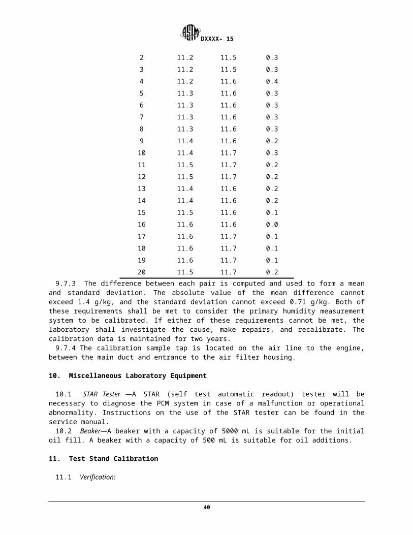
DXXXX– 15
its activities with the test sponsors, the test developers, the surveillance panels, and the testinglaboratories. Contact TMC through the TMC Director at:
ASTM Test Monitoring Center6555 Penn AvenuePittsburgh, PA 15206-4489www.astmtmc.cmu.edu
A1.2 Rules of Operation of the ASTM TMC—The TMC operates in accordance with theASTM Charter, the ASTM Bylaws, the Regulations Governing ASTM Technical Committees,the Bylaws Governing ASTM Committee D02, and the Rules and Regulations Governing theASTM Test Monitoring System.
A1.3 Management of the ASTM TMC—The management of the Test Monitoring System isvested in the Executive Committee elected by Subcommittee D02.B0. The Executive Committeeselects the TMC Director who is responsible for directing the activities of the TMC.
A1.4 Operating Income of the ASTM TMC—The TMC operating income is obtained from fees levied on the reference oils supplied and on the calibration tests conducted. Fee schedules are established by the Executive Committee and reviewed by Subcommittee D02.B0.
A2. ASTM TEST MONITORING CENTER: CALIBRATION PROCEDURES
A2.1 Reference Oils—These oils are formulated or selected to represent specific chemical, orperformance levels, or both. They are usually supplied directly to a testing laboratory under codenumbers to ensure that the laboratory is not influenced by prior knowledge of acceptable resultsin assessing test results. The TMC determines the specific reference oil the laboratory shall test.
A2.1.1 Reference Oil Data Reporting – Test laboratories that receive reference oils for standcalibration shall submit data to the TMC on every sample of reference oil they receive. If ashipment contains any missing or damaged samples, the laboratory shall notify the TMCimmediately.
A2.2 Calibration Testing:A2.2.1 Full-scale calibration testing shall be conducted at regular intervals. These full-scale
tests are conducted using coded reference oils supplied by the TMC. It is a laboratory'sresponsibility to keep the on-site reference oil inventory at or above the minimum level specifiedby the TMC test engineers.
A2.2.2 Test Stands Used for Non-Standard Tests—If a non-standard test is conducted on apreviously calibrated test stand, the laboratory shall conduct a reference oil test on that stand todemonstrate that it continues to be calibrated, prior to running standard tests.
A2.3 Reference Oil Storage—Store reference oils under cover in locations where the ambienttemperature is between -10 °C and +50 °C.
A2.4 Analysis of Reference Oil—Unless specifically authorized by the TMC, do not analyzeTMC reference oils, either physically or chemically. Do not resell ASTM reference oils orsupply them to other laboratories without the approval of the TMC. The reference oils aresupplied only for the intended purpose of obtaining calibration under the ASTM Test MonitoringSystem. Any unauthorized use is strictly forbidden. The testing laboratory tacitly agrees to usethe TMC reference oils exclusively in accordance with the TMC’s published Policies for Use andAnalysis of ASTM Reference Oils, and to run and report the reference oil test results accordingto TMC guidelines. Additional policies for the use and analysis of ASTM Reference Oils areavailable from the TMC.
A2.5 Conducting a Reference Oil Test—When laboratory personnel are ready to run areference calibration test, they shall request an oil code via the TMC website.
A2.6 Reporting Reference Oil Test Results—Upon completion of the reference oil test, the test laboratory transmits the data electronically to the TMC, as described in Section ?. The TMCreviews the data and contacts the laboratory engineer to report the laboratory's calibration status.All reference oil test results, whether aborted, invalidated, or successfully completed, shall bereported to the TMC.
40
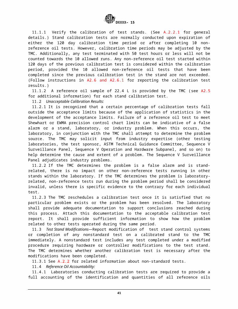
DXXXX– 15
A2.6.1 All deviations from the specified test method shall be reported.
A3. ASTM TEST MONITORING CENTER: MAINTENANCE ACTIVITIES
A3.1 Special Reference Oil Tests—To ensure continuous severity and precision monitoring,calibration tests are conducted periodically throughout the year. Occasionally, the majority oreven all of the industry’s test stands will conduct calibration tests at roughly the same time. Thiscould result in an unacceptably large time frame when very few calibration tests are conducted.The TMC can shorten or extend calibration periods as needed to provide a consistent flow ofreference oil test data. Adjustments to calibration periods are made such that laboratories incurno net loss or gain in calibration status.
A3.2 Special Use of the Reference Oil Calibration System—The surveillance panel has theoption to use the reference oil system to evaluate changes that have potential impact on testseverity and precision. This option is only taken when a program of donated tests is not feasible.The surveillance panel and the TMC shall develop a detailed plan for the test program. This planrequires all reference oil tests in the program to be completed as close to the same time aspossible, so that no laboratory/stand calibration status is left pending for an excessive length oftime. In order to maintain the integrity of the reference oil monitoring system, each reference oiltest is conducted so as to be interpretable for stand calibration. To facilitate the required testscheduling, the surveillance panel may direct the TMC to lengthen and shorten reference oilcalibration periods within laboratories such that the laboratories incur no net loss or gain incalibration status. To ensure accurate stand, or laboratory, or both severity assessments, conductnon-reference oil tests the same as reference oil tests.
A3.3 Donated Reference Oil Test Programs—The surveillance panel is charged withmaintaining effective reference oil test severity and precision monitoring. During times of newparts introductions, new or re-blended reference oil additions, and procedural revisions, it may benecessary to evaluate the possible effects on severity and precision levels. The surveillance panelmay choose to conduct a program of donated reference oil tests in those laboratories participatingin the monitoring system, in order to quantify the effect of a particular change on severity andprecision. Typically, the surveillance panel requests its panel members to volunteer enoughreference oil test results to create a robust data set. Broad laboratory participation is needed toprovide a representative sampling of the industry. To ensure the quality of the data obtained,donated tests are conducted on calibrated test stands. The surveillance panel shall arrange anappropriate number of donated tests and ensure completion of the test program in a timelymanner.
A3.4 Intervals Between Reference Oil Tests—Under special circumstances, such as extendeddowntime caused by industry-wide parts or fuel shortages, the TMC may extend the intervalsbetween reference oil tests.
A3.5 Introducing New Reference Oils—Reference oils produce various results. When newreference oils are selected, participating laboratories will be requested to conduct their share oftests to enable the TMC to recommend industry test targets. ASTM surveillance panels require aminimum number of tests to establish the industry test targets for new reference oils.
A3.6 TMC Information Letters—Occasionally it is necessary to revise the test method, andnotify the test laboratories of the change, prior to consideration of the revision by SubcommitteeD02.B0. In such a case, the TMC issues an Information Letter. Information Letters are ballotedsemi-annually by Subcommittee D02.B0, and subsequently by D02. By this means, the Societydue process procedures are applied to these Information Letters.
A3.6.1 Issuing Authority—The authority to issue an Information Letter differs according to itsnature. In the case of an Information Letter concerning a part number change which does notaffect test results, the TMC is authorized to issue such a letter. Long-term studies by thesurveillance panel to improve the test procedure through improved operation and hardwarecontrol may result in the issuance of an Information Letter. If obvious procedural items affectingtest results need immediate attention, the test sponsor and the TMC issue an Information Letterand present the background and data supporting that action to the surveillance panel for approvalprior to the semiannual Subcommittee D02.B0 meeting.
A3.7 TMC Memoranda—In addition to the Information Letters, supplementary memoranda
41
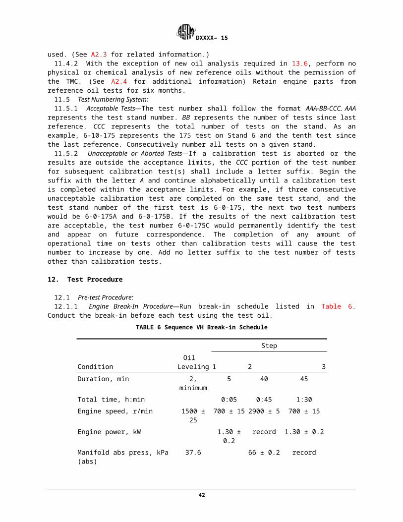
DXXXX– 15
are issued. These are developed by the TMC and distributed to the appropriate surveillance paneland participating laboratories. They convey such information as batch approvals for test parts ormaterials, clarification of the test procedure, notes and suggestions of the collection and analysisof special data that the TMC may request, or for any other pertinent matters having no directeffect on the test performance, results, or precision and bias.
A4. ASTM TEST MONITORING CENTER: RELATED INFORMATION
A4.1 New Laboratories—Laboratories wishing to become part of the ASTM Test MonitoringSystem will be requested to conduct reference oil tests to ensure that the laboratory is using theproper testing techniques. Information concerning fees, laboratory inspection, reagents, testingpractices, appropriate committee membership, and rater training can be obtained by contactingthe TMC Director.
A4.2 Information Letters: COTCO Approval—Authority for the issuance of InformationLetters was given by the committee on Technical Committee Operations in 1984, as follows:“COTCO recognizes that D02 has a unique and complex situation. The use of InformationLetters is approved providing each letter contains a disclaimer to the affect that such has notobtained ASTM consensus. These Information Letters should be moved to such consensus asrapidly as possible.”
A4.3 Precision Data—The TMC determines the precision of test methods by analyzing results of calibration tests conducted on reference oils. Precision data are updated regularly. Current precision data can be obtained from the TMC.
A 5. SAFETY PRECAUTIONS
A 5.1 General Information: A5.1.1 The operation of this procedure can expose personnel to hazardous materials, operations, and equipment.
Personnel who are involved in the design, installation, and operation should be thoroughly trained and experienced. Personnel should be provided with safety glasses, hearing protection, and proper tools. All loose clothing should be removed or secured.
A5.1.2 The laboratory facilities should be inspected and approved by the laboratory's safety department. All laboratory areas should be kept clean and free of oil and fuel spills. The laboratory should also be kept free of tripping hazards. Containers of fuel and oil should not be allowed to accumulate excessively. A fixed fire protection system and adequate fire extinguishers should be available in all parts of the laboratory. Emergency showers should be provided throughout the laboratory.
A5.1.3 The test stands should be equipped with a fuel shut-off valve that is designed to automatically interrupt the fuel supply when the engine is not running. The engine should also be automatically shutdown if any of the following events occur: dynamometer loses field current, engine overspeeds, exhaust system fails, room ventilation fails, or the fire protection system activates. Guards should be installed around all external rotating parts and hot surfaces. All fuel lines, oil lines, steam lines, process water lines, and electrical wiring should be properly routed, protected, and kept in good working order.
A5.1.4 This test method can expose personnel to physical hazards and various hazardous chemicals to prepare parts for the test. These chemicals and a summary of specific precautions concerning each chemical are listed below. Emergency showers and eye-rinse facilities should be provided in parts preparation areas.A5.2 Physical Hazards:
A5.2.1 Electrical shock.A5.2.2 High-speed rotating equipment.A5.2.3 High-temperature surfaces.A5.2.4 Noise.
A5.3 Hazardous Chemicals and Materials: A5.3.1 Solvent (meeting Specification D235, Type II, Class C requirements) (See 7.7.1):A5.3.1.1 Before opening the container, relieve pressure. Keep the container tightly closed when not in use.A5.3.1.2 Store at moderate temperatures and keep away from heat, sparks, open flame, oxidizing agents, acids,
and bases.A5.3.1.3 Use dry chemical, foam, or CO2 as extinguishing media.
42
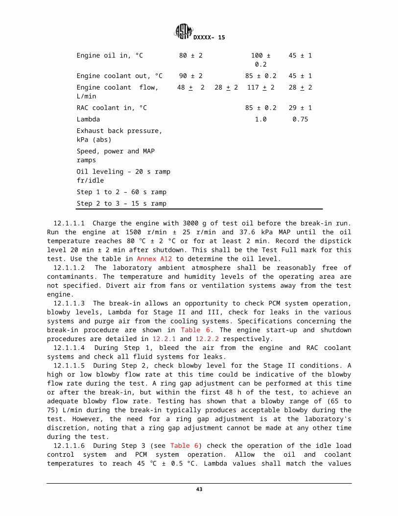
DXXXX– 15
A5.3.1.4 Use safety glasses and impervious gloves when handling.A5.3.1.5 Use cartridge or air-line respirators in enclosed areas.A5.3.1.6 Use only if adequate ventilation is available. A5.3.1.7 Avoid contact with eyes, skin, and clothing.A5.3.2 Cooling System Cleanser, (DuPont formulation or equivalent):A5.3.2.1 Store at moderate temperatures. Keep container closed until use.A5.3.2.2 Use safety glasses and impervious gloves when handling.A5.3.2.3 Use respiratory protection in absence of proper environmental control.A5.3.2.4 Use only if adequate ventilation is available. A5.3.2.5 Avoid contact with eyes, skin, and clothing.A5.3.3 Acidic Cleaner with Inhibitor (Dearsol 134):A5.3.3.1 Store at moderate temperatures. Keep container closed until use.A5.3.3.2 Use safety glasses and impervious gloves when handling.A5.3.3.3 Use respiratory protection in absence of proper environmental control. Use only if adequate ventilation
is available.A5.3.3.4 Avoid contact with eyes, skin, and clothing.A5.3.4 Unleaded Gasoline (Haltermann VH Fuel)—(Warning—Flammable. Health hazard.) A5.3.4.1 Before opening the container, relieve pressure. Keep the container tightly closed when not in use.A5.3.4.2 Store at moderate temperatures and keep away from heat, sparks, open flame, and oxidizing agents.A5.3.4.3 Use dry chemical, foam, or CO2 as extinguishing media.A5.3.4.4 Use safety glasses and impervious gloves when handling.A5.3.4.5 Use respiratory hydrocarbon vapor canisters in enclosed areas.A5.3.4.6 Use only if adequate ventilation is available. A5.3.4.7 Avoid contact with eyes, skin, and clothing.A5.3.5 New and Used Oil Samples:A5.3.5.1 Store at moderate temperatures and keep away from extreme heat, sparks, open flame, and oxidizing
agents.A5.3.5.2 Use dry chemical, foam, or CO2 as extinguishing media.A5.3.5.3 Use safety glasses and impervious gloves when handling.A5.3.5.4 Avoid contact with eyes, skin, and clothing.A5.3.5.5 Used Oil Samples Only—(Warning—Health hazard.) Since used oils contain compounds that were not
originally present in the new oil, follow the most stringent Material Safety Data Sheets guidelines for all components present. In addition to other precautions, note that continuous contact with used motor oils has caused skin cancer in laboratory mice.
A5.3.6 Organic Solvent (Penmul):A5.3.6.1 Before opening the container, relieve pressure. Keep the container tightly closed when not in use.A5.3.6.2 Store at moderate temperatures and keep away from heat, sparks, open flame, and strong oxidizing
agents.A5.3.6.3 Use dry chemical, foam, or CO2 as extinguishing media.A5.3.6.4 Use safety glasses and impervious gloves when handling.A5.3.6.5 Use respiratory hydrocarbon vapor canister in enclosed area.A5.3.6.6 Use only if adequate ventilation is available. A5.3.6.7 Avoid contact with eyes, skin, and clothing.
A6. CONTROL AND DATA ACQUISITION REQUIREMENTS
A6.1 General Description: A6.1.1 The data acquisition system shall be capable of logging the operational data in digital format. It is to the
advantage of the laboratory that the system be capable of real time plotting of controlled parameters to help assess test validity. The systems shall be capable of calculating real time quality index as this will be monitored throughout the test as designated in A6.5
A6.1.2 Control capability is not dictated by this procedure. The control system shall be capable of keeping the controlled
parameters within the limits specified in Table 2 (see 8.3.5) and maintain the quality index described in A6.5A6.1.3 Design the control and data acquisition system to meet the requirements listed below. Use the
recommendations laid out in the Instrumentation Task Force Report and Data Acquisition Task Force Report for any
43
DXXXX– 15
items not addressed in Annex A6.A6.2 Digital Recording Frequency—The maximum allowable time period over which data can be accumulated
is one second. This data can be filtered, as described in A6.6, and will be considered a reading.A6.3 Steady State Operation: A6.3.1 This portion of the test will start, at most, 20 min after the beginning of a transition and continue until the
beginning of the next stage. By 20 min into a stage all parameters shall be in the steady state condition listed in Table 2. The start of the transition is considered the start of the stage. Calculate the quality index using values reported to the accuracy levels in Table A6.1.
TABLE A6.1 Accuracy Levels of Data Points to be Used in QI CalculationsParameter Field Length
Speed 5.0Humidity 5.1Temperature 5.1Manifold Absolute Pressure 5.1Intake Air Pressure 6.3Exhaust Backpressure 6.1Coolant Outlet Pressure 6.1Coolant Flow 6.1
TABLE A6.2 L and U Constants and Over and Under-Range Values TBDParameter Stages L U Over-
RangeUnder-Range
Coolflow 1 47.47 48.53 87.0 0
Cooloutt 1 56.71 57.29 113.0 02 84.71 85.29 113.0 0
3 44.71 45.29 113.0 0
Exhbprs 1 103.83 104.17 115.0 02 106.83 107.17 115.0 0
Humidity 1, 2, 3 10.85 11.95 64.0 0
Intairpr 1, 2, 3 0.04 0.06 1.05 0
Intairt 1, 2, 3 29.80 30.20 49.0 0
Oilint 1 67.79 68.21 120.0 02 99.79 100.21 120.0 0
3 44.79 45.21 120.0 0
Speed 1 1198.1 1201.9 3156.0 02 2898.1 2901.9 3156.0 0
3 698.1 701.9 3156.0 0
Map 1 68.60 69.40 76.0 02 65.60 66.40 76.0 0
Cooloutp 1, 2, 3 69.35 70.65 159.0 0
Raccint 1, 3 28.63 29.37 120.0 0
44
DXXXX– 15
2 84.63 85.37 120.0 0
Raccfl 1, 2, 3 14.85 15.15 29.0 0
TABLE A6.3 Maximum Allowable Time ConstantsControl Parameter Time Constant, s
Engine speed, r/min 1.9Manifold abs press, kPa 1.8Engine oil in, °C 2.4Engine coolant out, °C 2.4Engine coolant flow, L/min 17.0RAC coolant in, °C 2.4Rocker cover flow, L/min 2.0Intake, air, °C 2.4Intake air press, kPa 2.6Exhaust back pressure, kPa 1.7Engine coolant pressure 2.0
A6.3.2 The time intervals between recorded readings shall not exceed 1 min. Record data throughout the length of the steady state portion of each stage.A6.4 Transitions :
A6.4.1 This portion of the test shall be, at most, the first 20 min of each stage. Ramping requirements are listed in Table 4.
A6.4.2 During the transition, the time intervals between recorded readings shall not exceed 1 min.A6.5 Quality Index:
A6.5.1 Calculate and record the quality index for each controlled parameter for the steady state portion of each test stage throughout the entire test.
A6.5.2 Update the quality index periodically throughout the test to determine the operational validity while the test is in progress. This could indicate if the test operational validity is in question before the test has completed.
A6.5.3 Use the following equation and the values listed in Table A6.2 to calculate the Qi.
where:Xi = values of the parameter measured,U = allowable upper limit of X,L = allowable lower limit of X, andn = number of measurements taken.
A6.5.4 Reset data that is greater than the over-range values listed in Table A6.2 with the over-range value listed in Table A6.2.
A6.5.5 Reset data that is lower than the under-range values listed in Table A6.2 with the under-range value listed in Table A6.2.
A6.5.6 Round the Qi values to the nearest 0.001.A6.5.7 Report the Qi values on Form 6 of the test report.A6.5.8 If the end-of-test Quality index value is below 0.000 for reference oil tests, review the test operations with
the TMC. The TMC issues a letter to the laboratory and the test sponsor on its opinion.
45
DXXXX– 15
A6.5.8.1 The laboratory documents its comments regarding the end-of-test Quality index values less than 0.000 for non-reference oil tests. The laboratory or test sponsor might request TMC review of test operations for non-reference oil tests. The TMC issues a letter to document its opinion.A6.6 Time Constants:
A6.6.1 Filtering can be applied to all control parameters. The amount of filtering applied shall not allow time constants to exceed the values listed in Table A6.3. This time constant shall pertain to the entire system, running from the sensor to the display and data acquisition.
A6.6.2 Maximum allowable system time constants for the controlled parameters are shown in Table A6.3.
A7. DETAILED SPECIFICATIONS AND PHOTOGRAPHS OF APPARATUS
A7.1 Figs. A7.1 to A7.28 show the detailed specifications and photographs of apparatus.
46
DXXXX– 15
FIG. A7.1 Air Cleaner Housing Modifications
47
DXXXX– 15
FIG. A7.2 Engine Air Intake System Assembly and Connections
48
DXXXX– 15
FIG. A7.3 Camshaft Baffle
49
DXXXX– 15
FIG. A7.4 Rocker Arm Cover with Water Jacket, Left
50
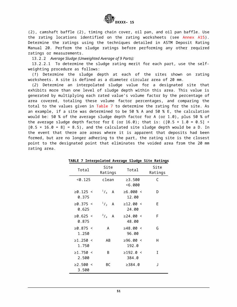
DXXXX– 15
FIG. A7.5 Rocker Arm Cover with Water Jacket, Right
51
DXXXX– 15
FIG. A7.6 Oil Level Indicator (Dipstick)
52
DXXXX– 15
FIG. A7.7 Oil Pan Assembly with Removable Baffles
53
DXXXX– 15
NOTE 1—(1) External oil filter adapter with temperature in sensor and oil pressure gage taps, OHT6A-007-1 (2) Oil filter, OHT6A-012-2, with steel relief valve and 60 μm screen (3) Temperature sensor oil out (4) Temperature control sensor oil in (5) Oil sample valveNOTE 2—External system oil volume 570 ± 30 mL.
FIG. A7.8 Oil Cooling System Specification
54
DXXXX– 15
NOTE 1—Dimensions are in millimetres; Tolerances: ±0.13; Material: aluminum.
FIG. A7.9 Piston Ring Positioner
55
DXXXX– 15
NOTE 1—The inlet flow meter must calibrate to within 5 % of the standard (pre-calibrated) orifices at the pressure differentials stamped on the orifices.
FIG. A7.10 PCV Valve Flow Test Apparatus
FIG. A7.11 Water Pump Block off plate and Thermostat Housing Orifice
FIG. A7.12 Idle Air Control
56
DXXXX– 15
NOTE 1—Dimensions are in millimetres.
FIG. A7.13 MAP Port / EGR Block Off Plate
FIG A7.14 Typical Exhaust System Cooling System
57
DXXXX– 15
FIG. A7.15 Typical Exhaust System, Engine to Laboratory Exhaust
58
DXXXX– 15
NOTE 1—Dimensions are in millimetres.
FIG. A7.16 Typical Laboratory Exhaust System
59
DXXXX– 15
FIG. A7.17 Closed Crankcase Ventilation System, Typical Fittings and Parts Configuration
60
DXXXX– 15
NOTE 1—Observe temperature sensor locations in thermostat housing and at water pump inlet.NOTE 2—Components of Engine Cooling System— (1) Thermostat housing with temperature sensor (2) Sight glass (3) Flowmeter(4) Flow control valve (5) Optional temperature control sensor (6) Fabricated coolant reservoir (7) Constant full expansion tank (8) Pressure radiator cap (MOTORCRAFT RS40 P/N D2YY-8100-A) (9) Process water control valve (regulated by temperature controller with three remote set points) (10) Heat exchanger (ITT Standard P/N 5-030-06-048-001 TYP.) (11) Process water supply (shell side) (12) Tee with temperature sensor for coolant inlet; located (300 to 400) mm upstream of pump inlet at the block face (13) Water pump inlet (Oil filter adapter)(14) Engine coolant (tube side) (15) Coolant system drain valve (16) Coolant pressure regulator (17) Coolant pressure gage(18) External coolant pump
FIG. A7.18 Typical Engine Cooling System Schematic
61
DXXXX– 15
FIG. A7.19 Typical Test Stand, Left Forward View
FIG. A7.20 Typical Test Stand, Right Forward View
62
DXXXX– 15
FIG. A7.21 Intake Air Supply System, Air Cleaner, Resonator and Idle Load Control (Replace)
63
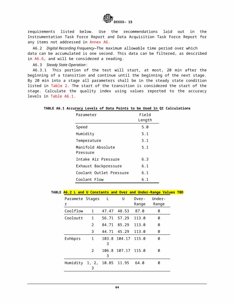
DXXXX– 15
FIG. A7.22 Typical Engine Cooling System
FIG. A7.23 Typical Cooling System, Flow Control Valve, Venturi Flowmeter, Reservoir and Sight Glass (Replace)
64
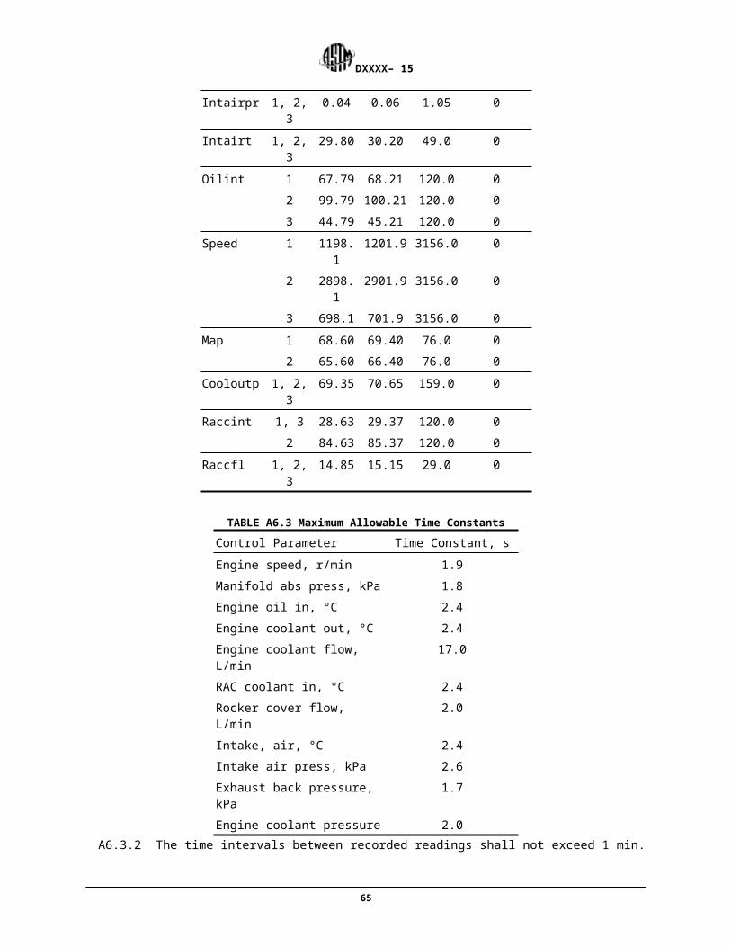
DXXXX– 15
FIG. A7.24 Oil Cooling System Required Heat Exchanger Mounting and Typical Hoses and Fittings
FIG. A7.25 Oil Cooling System, Adapter Housing at the Engine with Typical Fittings for Temperature Sensors, Pressure Tap and Oil Filter
65
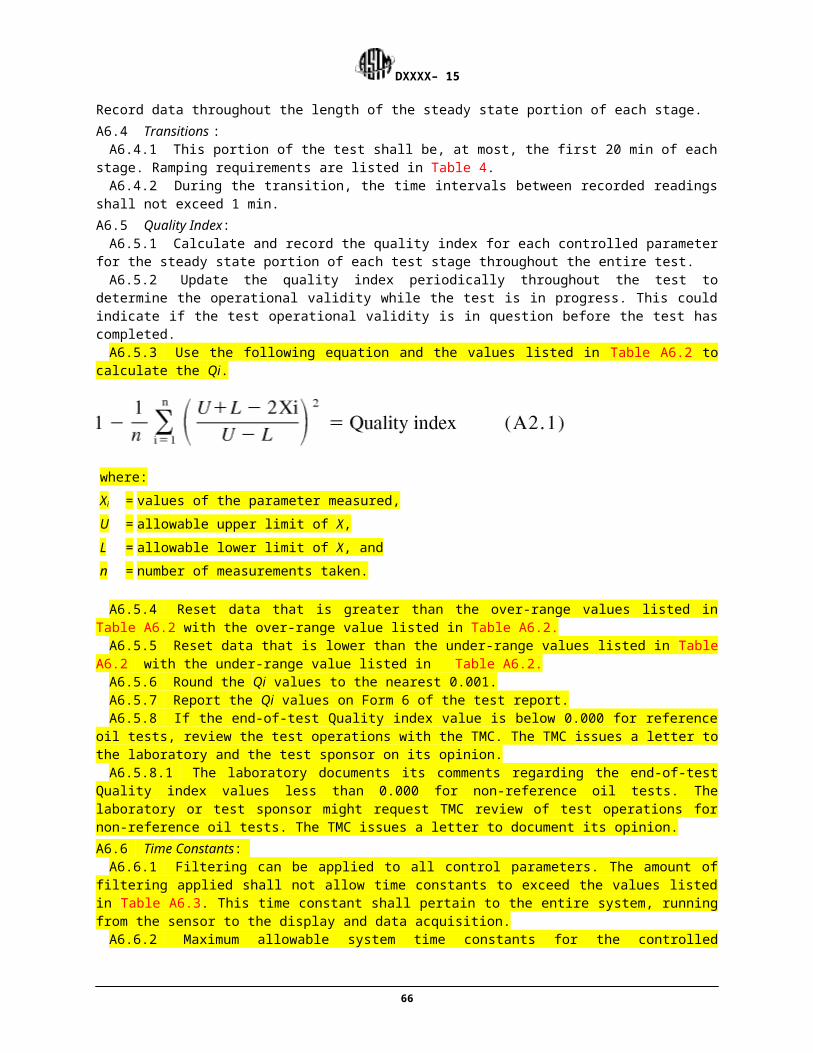
DXXXX– 15
FIG. A7.26 Engine Ventilation System
66
DXXXX– 15
FIG. A7.27 Engine Ventilation System, 3-Way Valve (Replace)
67
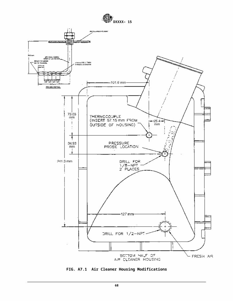
DXXXX– 15
FIG. A7.28 Bore Measurement Ladder
68
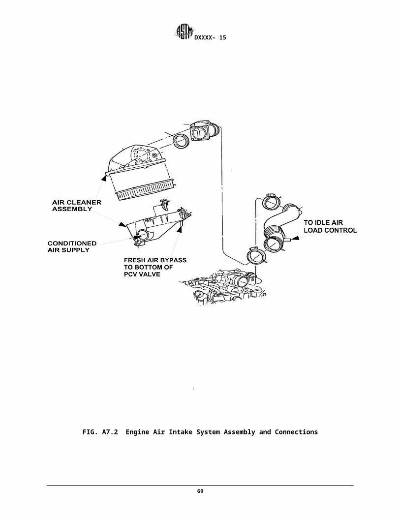
DXXXX– 15
A8. SPECIAL SERVICE TOOLS FOR THE TEST ENGINE
A8.1 Table A8.1 lists special tools needed for the test engine.
TABLE A8.1 Special ToolsTool No. DescriptionD81L-6135-A Piston pin remover and replacerT80T-4000-W Driver handleT91P-6571-A Valve stem seal replacerT91P-6565-A Valve spring compressorT91P-6565-AH Valve spring spacer
A9. TEST ENGINE PART NUMBER LISTING
Table A9.1 Engine parts
SERVICE PART NUMBERENGINEERINGPART NUMBER
DESCRIPTION
1L2Z-6250-AA 1L2E-6250-DA CAMSHAFT RH1L2Z-6250-DA 1L2E-6A274-CA CAMSHAFT LH1L2Z-6L253-AA 1L2E-6L253-AA GUIDE, TIMING CHAIN TENSIONER LH1L2Z-6L253-BA 1L2E-6L253-BA GUIDE, TIMING CHAIN TENSIONER RH1L3Z-6L266-AA 1L3E-6L266-AG TENSIONER, TIMING CHAIN, RHXL1Z-6L266-AA 1L3E-6M269-AC TENSIONER, TIMING CHAIN, LH1W7Z-6312-A 1W7E-6316-AF PULLY, CRANKSHAFT1W7Z-6B288-AB 1W7E-6B288-AB SENSOR, CAMSHAFT1W7Z-6C315-AA 1W7E-6C315-AA SENSOR, CRANKSHAFT POSITION391186S101 391186 PLUG, SIDE OF BLK3L2Z-6345-AAA 3L2E-6345-AA BOLTS, MAIN BEARING CAP
XW7E-6C357-AB BOLTS, MAIN BEARING CAP SIDE3L2Z-6345-AA 3L2E-6K258-AA BOLTS, MAIN, OIL PUMP PICK UP TUBE4R3Z-6B274-BA 4R3E-6B274-BA GUIDE, TIMING CHAIN LH4R3Z-6M256-CC 4R3E-6M256-CC GUIDE, TIMING CHAINRH5C3Z-6211-A 5C3E-6211-BA BEARING - CONNECTING ROD (1u&l)5L3Z-6600-AA 5L3E-6621-AA PUMP ASY - OIL5R3Z-6065-AA 5R3E-6065- AA BOLTS, CYLINDER HEAD (10 bolts)5W7Z-6268-AA 5W7E-6268-AA CHAIN, TIMING
6L3E-6148-DA PISTON RINGS 0.125 O/S6L3E-6148-EA PISTON RINGS 0.25 O/S6L3E-6148-FA PISTON RINGS 0.0.375 O/S6L3E-6148-GA PISTON RINGS 0.5 O/S
6W7Z-6505-BA 6W7E-6505-BA VALVE, EXHAUSTBL2Z-6D309-A BL2E-6D309-AA BEARING - CRANKSHAFT MAIN (1u&l)BL2Z-6D309-B BL2E-6D309-BA BEARING - CRANKSHAFT MAIN THRUST (1u&l)BR3Z-6A341-A BR3E-6A341-BA BEARING - CRANKSHAFT MAIN, THRUST WASHERF1AZ-6518-A F1AE-6518-BA KEY, VALVE RETAINERF3LY-6214-A F2LE-6214-BA BOLTS, CONNECTING ROD (4bolts)F3AZ-6265-A F4AE-6265-AA SPACER, CAMSHAFT GEARF6DZ-6C501-AB F65E-6C501-AB TAPPET - VALVEF6AZ-6514-AC F6LE-6514-AC RETAINER, VALVE SPRINGF8AZ-6564-AA F6TE-6529-AB ARM ASY - VALVE ROCKER
69
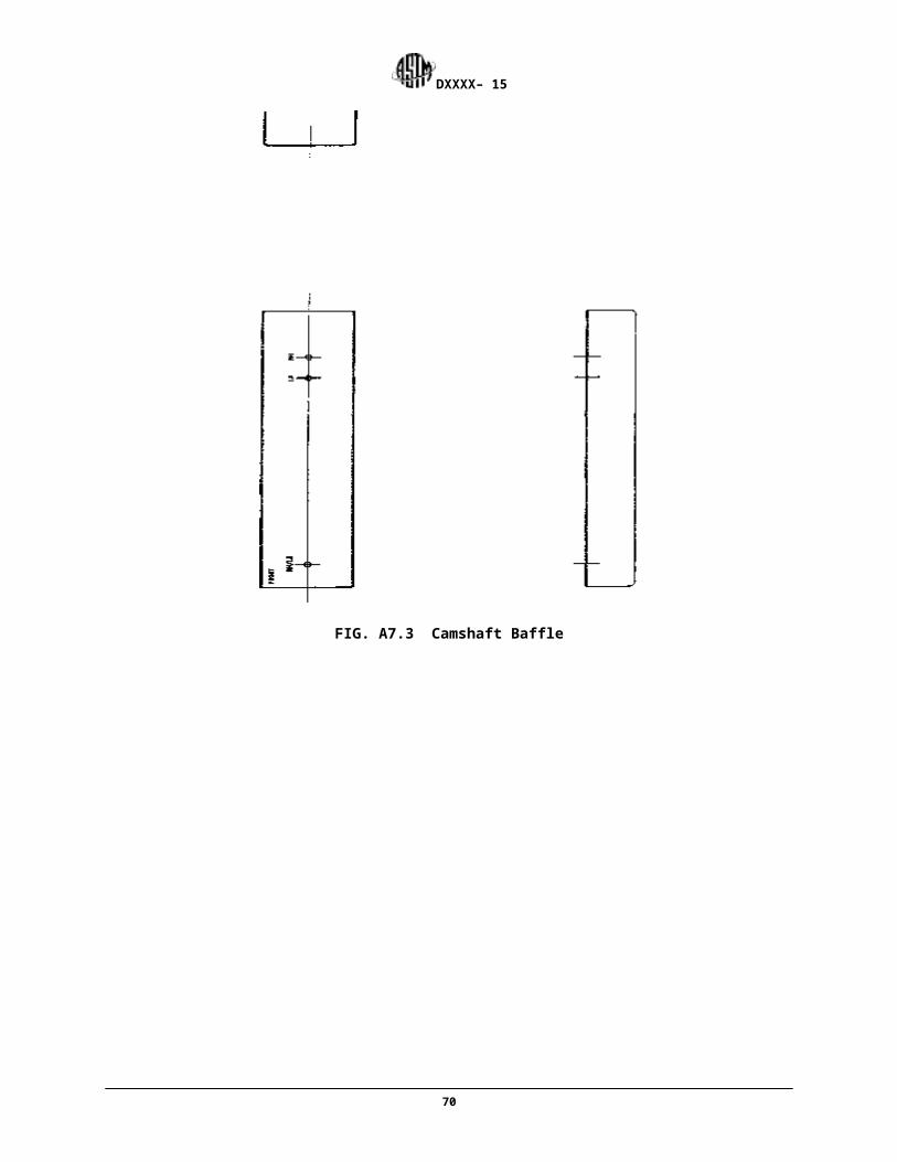
DXXXX– 15
F8AZ-6256-AA F8AE-6256-AA SPROCKET - CAMSHAFT RHF8AZ-6256-BA F8AE-6256-BA SPROCKET - CAMSHAFT LHXL3Z-6306-AA XL3E-6306-AB GEAR, TIMING CHAIN CRANKSHAFTXL3Z-6507-AA XL3E-6507-AC VALVE, INTAKEXL3Z-6513-AA XL3E-6513-AC SPRING, VALVEXW1Z-12A227-AC XW1E-12A227-AC WHEEL, CRANKSHAFT PICK UPAGSF-32P-M 3L1E-12405-AA PLUG, SPRK
3U1L-6110-AB PISTONS 0.125 O/S3U1L-6110-BB PISTONS 0.375 O/SYU1L-6110-BC PISTONS 0.250 O/SYU1L-6110-CC PISTONS 0.500 O/S6W7E-6049-AB CYLINDER HEAD 7L2E-6010-BA CYLINDER BLOCK2C5E-6303-B13A CRANKSHAFT
Table A9.2 Engine Dress Parts
SERVICE PART NUMBER
ENGINEERINGPART NUMBER
DESCRIPTION
F0TZ-9F593-DA F0TE-9F593-D9B INJECTORS, FUEL (PURPLE)6W7Z-6019-AA 6W7E-6C086-AA COVER - CYLINDER FRONT
.
Table A9.3 Stand Set Up Parts
SERVICE PART NUMBER
ENGINEERINGPART NUMBER
DESCRIPTION
4W7Z9B659CA 4W73-9R530-AA TUBE, FRESH AIR9L3Z-8592-B 9L3E-8594-BA CONNECTOR, WATER OUT
F3AE-12A166-BD BRACKET, IGNITION COILF6AE-12257-EB BRACKET, IGNITION COIL
3W7Z-9600-BA 3W7U-9600-BC ASSEMBLY, AIR CLEANER9W7Z-9424-A 9W7E-9424-AA MANIFOLD ASY - INLETE5TZ-9601-B E5TE-9601-AB ELEMENT, AIR FILTER
D8ZE-6A666-A2B PCV Valve (EV-98)
Table A9.4 Gaskets/Seals
SERVICE PART NUMBER
ENGINEERINGPART NUMBER
DESCRIPTION
3W7Z-6E078-AA 3W7E-6G050-AA Gasket set4C2Z-9439-CA 4C2E-9439-CB GASKET, INTAKE MANIFOLD4L2Z-6584-BA 4L2E-6584-BA GASKET, ROCKER ARM COVER, RH4L2Z-6584-AA 4L2E-6A559-BA GASKET, ROCKER ARM COVER LH5C2Z-9E936-BA 5C2E-9E930-BA GASKET, THROTTLE BODY TO SPACER
70
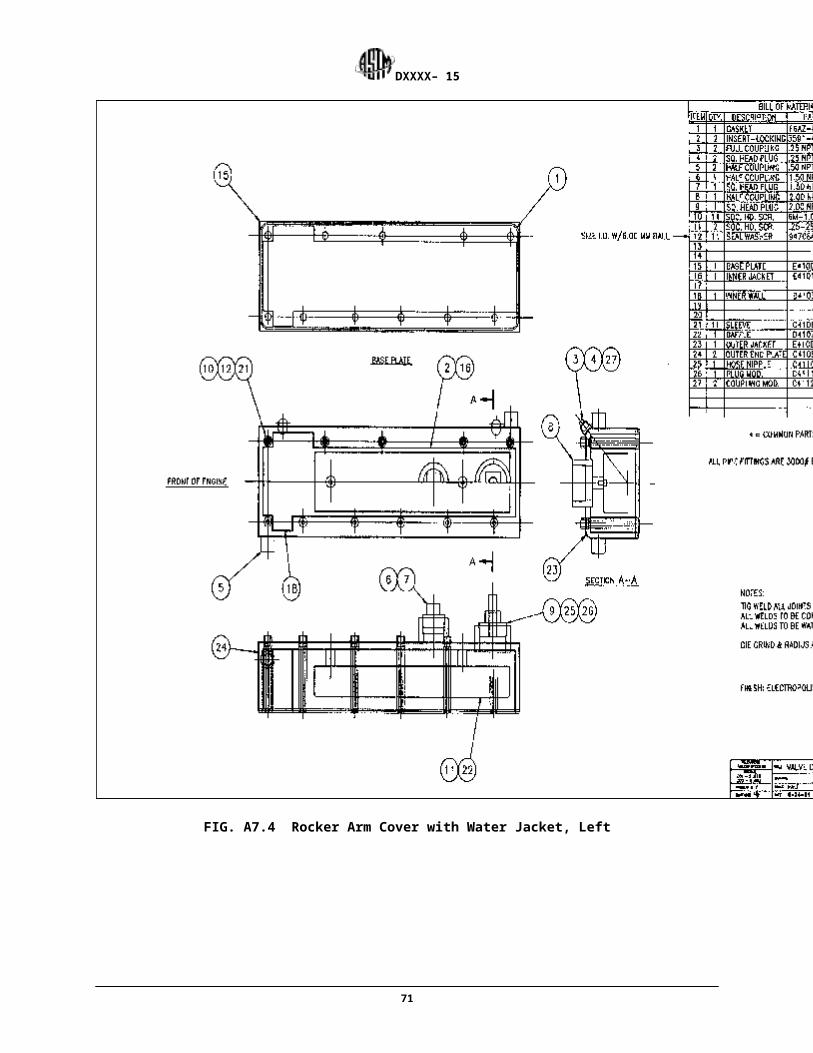
DXXXX– 15
5W7Z-8C387-AA 5W7E-8C387-AA GASKET, WATER CROSSOVER RH5W7Z-8C388-AA 5W7E-8C388-AA GASKET, WATER CROSSOVER LH6L3Z-6K301-AA 6L3E-6K318-AA RETAINER - CRANKSHAFT OIL SEAL9W7Z-6051-B 9W7E-6083-AB GASK, CYLINDER HEAD, LH9W7Z-6051-A 9W7E-6051-AB GASKET, CYLINDER HEAD, RH9W7Z-6079-A 9W7E-6079-AA Gasket setF1AZ-6020-A F1AE-6D081-AD GASKET, FRONT COVERF5AZ-6700-A F3AE-6700-AC SEAL, FRONT MAINF4AZ-6701-A F3AE-6701-BA SEAL, REAR MAINF4AZ-6571-A F4AE-6A517-AA SEAL, VALVE STEMF65Z-6840-A F65E-6A636-CA GASKET, OIL FILTER ADPTXR3Z-9L437-BA XR3E-9L437-BA GASKET, THROTTLE BODY SPACER TO INTAKEF1VY-8507-A 391108-S SEAL, WATER PUMP3L3Z-6710-AA 3L3E-6710-AA GASKET, OIL PAN3W7Z-6625-AA 3W7E-6625-A3A ORING, OIL PUMP PICK UP TUBEYC2Z-9448-A YC2E-9Y431-AD GASKET, EXHAUST MANIFOLDF1VY-8255-A N806807 SEAL - THERMOSTAT
Table A9.5 FastenersPART NUMBER LOCATIONN606527 GUIDE, TIMING CHAINN804958 GUIDE, TIMING CHAINN806040 PINS, OIL PUMPN806154 THROTTLE BODY ELBOW TO INTAKEN806155 REAR SEAL HSGN806155 CAMSHAFT POSITION SENSORN806155 CRANKSHAFT POSITION SENSORN806164 WASHER, GEAR TO CAMSHAFTN806165 WASHER, CRANKSHAFT PULLEYN806177 TIMING CHAIN TNESIONERN806177 FRONT COVERN806177 WATER PUMPN806183 OIL PUMPN806300 FRONT COVERN807198S SLEEVE - GUIDE, BELL HOUSINGN808586 FRONT COVERN811085 SPROCKET TO CAMSHAFTW503279 TIMING CHAIN GUIDEW503301 INTAKE MANIFOLDW506102-S437 THROTTLE BODY TO SPACERW701228S300 DOWEL, FRONT AND REAR COVERSW701512 PULLEY, CRANKSHAFTW701605 OIL PANW704594S300 DOWEL - PIN, BLOCK TO CYLINDER HEADW704693 WATER OUT CONNECTORW705128 OIL FILTER ADAPTER
71
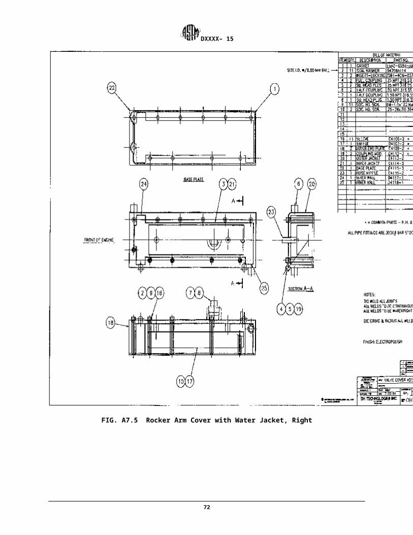
DXXXX– 15
W706508 FRONT COVERW715986S900 PLUG - BLOCK FRONT, WATER PUMP
Table A9.6 Engine Finish Parts
SERVICE PART NUMBERENGINEERINGPART NUMBER
DESCRIPTION
7U2Z-12029-B 7U2J12029AB COIL ASY - IGNITION5W7Z-9F792-AC 5W7E-9F792-AD MANIFOLD ASSY, FUELF6ZZ-12B579-AARM RMF6ZF-12B579-AB SENSOR,MAFF8PZ-12259-LAFC F8PE 12259 LA WIRES, SPARK PLUG
A10. EXTERNAL OIL HEAT EXCHANGER CLEANING TECHNIQUE
A10.1 Remove and completely disassemble the heat exchanger including the end caps.A10.2 Flush the shell side of the heat exchanger with an organic solvent for a minimum of 12 h to ensure the removal of all deposits. This can be accomplished by using a positive displacement pump to flow the solvent through the heat exchanger at a flow rate of 0.63 L/s ± 0.126 L/s. Several heat exchangers can be flushed at the same time by connecting them in series. Flushing can be required for longer than 12 h if the deposits are particularly heavy or the solvent is aged. Filtration of the solvent can extend the useful life of the solvent.A10.3 Rinse the heat exchanger with hot water.A10.4 Rinse the heat exchanger with degreasing solvent (see 7.7.1).A10.5 Air-Dry Heat Exchanger:
NOTE A10.1—The tube side of the heat exchanger should be periodically cleaned to ensure adequate heat transfer. A rifle bore cleaner attached to an electric drill has been found to be an effective way to remove process water deposits. Ultrasonic cleaning is also effective in this application.
A11. SEQUENCE VG REPORT FORMS AND DATA DICTIONARY
A11.1 Download the actual report forms and data dictionary separately from the ASTM Test Monitoring Center Web Page at http://www.astmtmc.cmu.edu/, or they can be obtained in hardcopy format from the TMC.
Table of Contents
1. Title / Validity Declaration Page Form 12. Table of Contents Form 23. Summary of Test Method Form 34. Test Result Summary Form 45. Test Results Summary Form 56. Operational Summary Form 67. Oil Addition Record and Blowby Rates Form 78. Analysis of Oil Form 89. Downtime Occurrences and Other Comments Form 9NOTE 1—If the non reference oil test results are also to be submitted as candidate oil test results to the registration organization, use the report forms and data dictionary (that are maintained for reporting reference oil results) for reporting the candidate oil test results. Include the ACC Code of Practice Test Laboratory Conformance statement.10. ACC Conformance Statement
72
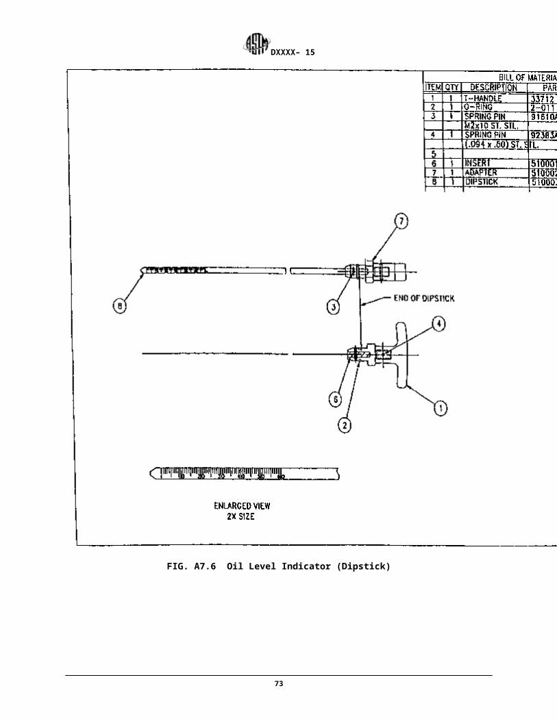
DXXXX– 15
A12. DIPSTICK CALIBRATION
A12.1 A typical dipstick calibration is presented in Fig. A12.1 and Table A12.1.
Sequence VG Dipstick Correlation:
Slope = 21 g/mm
Offset = 1953 mm
FIG. A12.1 Typical Dipstick Calibration
TABLE A12.1 Typical Dipstick CalibrationNOTE 1—The dipstick level is measured from the bottom of the dipstick up, zero being at the bottom and 60 mm at the top. The minor increments are 1 mm each. Always insert the dipstick with the words “Engine Oil” facing up. Read the oil level at the centerline of the dipstick.
Dipstick, mm Total Oil, g
0 19531 19742 19953 20164 20375 20586 20797 21008 21219 214210 216311 218412 220513 222614 224715 226816 228917 2310
73
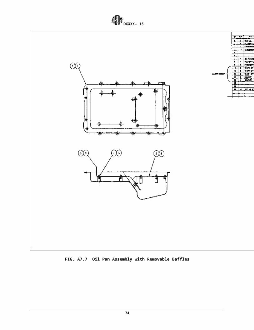
DXXXX– 15
Dipstick, mm Total Oil, g18 233119 235220 237321 239422 241523 243624 245725 247826 249927 252028 254129 256230 258331 260432 262533 264634 266735 268836 270937 273038 275139 277240 279341 281442 283543 285644 287745 289846 291947 294048 296149 298250 300351 302452 304553 306654 308755 310856 312957 3150
74

DXXXX– 15
Dipstick, mm Total Oil, g58 317159 319260 3213
A13. CRITICAL PART SUPPLIER LIST
A13.1 Test Engine Parts—The required parts for use in the VH test procedure are for the 4.6 L 2V engine which are supplied by the test sponsor (Ford Motor Company) through Ford Component Sales:
Ford Motor Co.290 Town Center DrDearborn, MI 48126
A13.2 Various Materials—RAC kitsCamshaft bafflesOil filter housing, Modified Racor oil filterOil oil screen, LFS-6028WCFOil filter adaptersDipstick assembly with tubeExhaust manifoldsOil pan and baffles,Oil Pan InsulationWater pump cover, OHT 6A-014-1Thermostat orifice, OHT 6A-004-1FlywheelAre available from the following supplier:
OH Technologies9300 Progress Pkwy.Mentor, OH 44060
A13.3 Various Materials—Exhaust manifold spacerCamshaft bearingsValve deck rating templatesOil Screen Blowdown DeviceAre available from the following supplier:
Test Engineering, Inc.12758 Cimarron Path, Ste. 102San Antonio, TX 78249-3417
A13.4 Test engine Parts – Connecting rods, Part Number F3AZ-6200-A/F3AE-6200-AAThrottle bodies, Part Number F3PE-9E926-NBThrottle body spacers Part Number 5W7Z-9A589-AA/5W7E-9A589-BBAre available from the following supplier:
Bishop International, Inc.224 North Corinth St.Dallas, TX 75203Toll-free: 800–843–5068
75
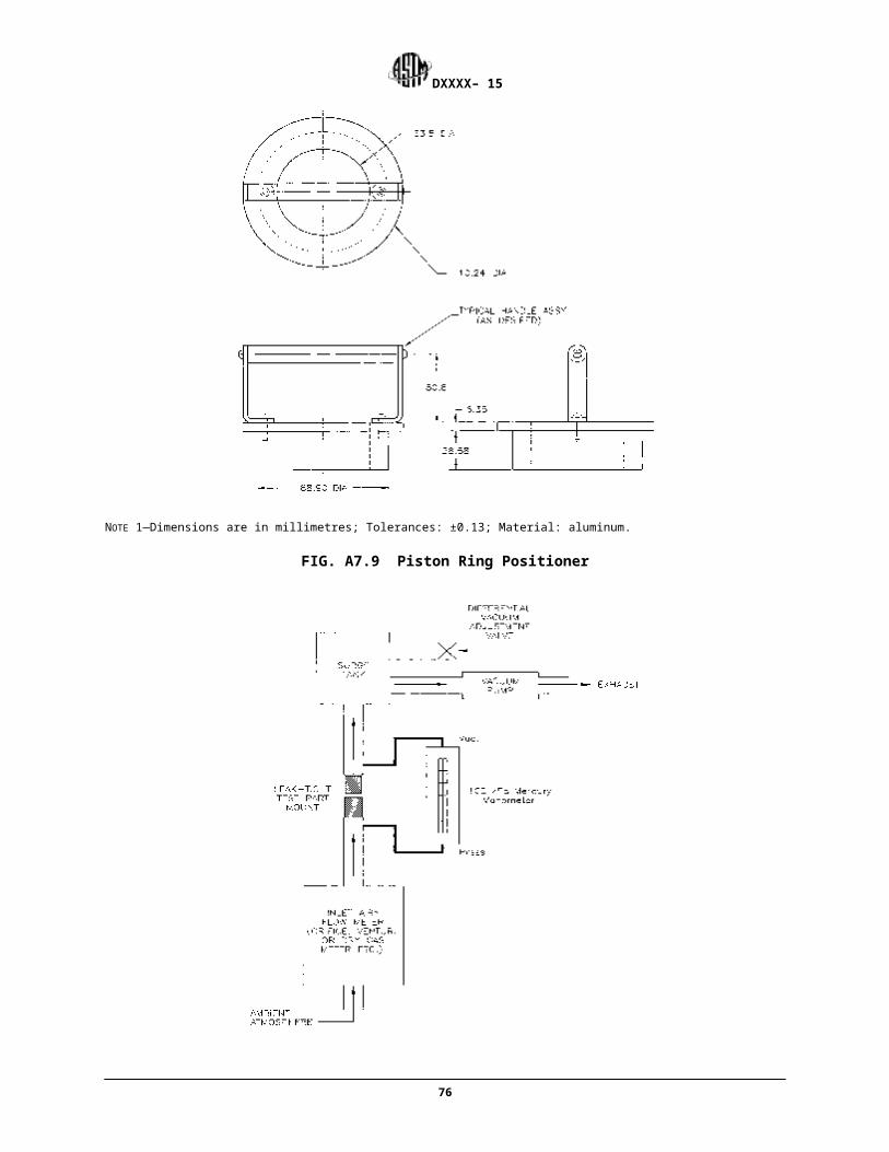
DXXXX– 15
Cunningham Brothers Auto Parts10980 Wards RoadRustburg, VA 24588800-828-0707
A13.5 Cylinder Head Modifications—cam bore machining and valve guide installation are available from the following supplier:
E&E Engine Machine and Parts1602 South FloresSan Antonio, TX 78204(210) 225–1141
A13.6 Oil separator Moroso Part number 85487 Are available from the following suppliers:American Muscle 1-888-322-1944Summit Racing 1-800-230-3030
A13.7 Wire harnesses are available from the following supplier:Ron Francis wire harnesses
A13.8 Powertrain Control Module are available from the following supplier:
A13.9 Lambda measuring device:Processor: Horiba Mexa 730, category # RX-721-57-BO2 Sensors: Horiba Model # 3200202803, category # 3YX5-1004Are available from the following supplier:
A13.10 Coolant PumpGOULD 1SPG5B4Is available from the following supplier:
A13.11 Variable Frequency DriveToshiba Model VFS15-2022PM-W.
Is available from local suppliers
76
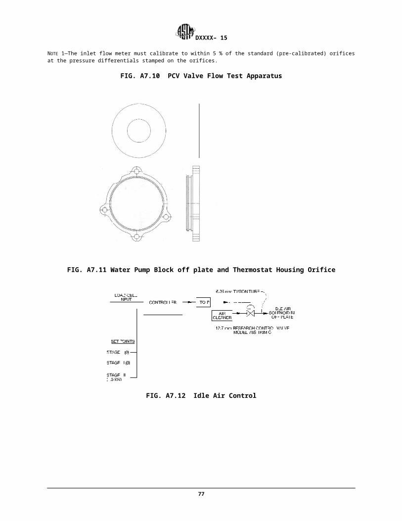
DXXXX– 15
A14. OPERATIONAL DATA LOG—ENGINE OIL
A14.1 See Fig. A14.1 for oil sampling, addition, and leveling record.
FIG. A14.1 Oil Sampling, Addition and Leveling Record
Note: Need to change heading of Fig. to VH (from VG)
A15. RATING WORKSHEETS
A15.1 Rating worksheets are provided in Figs. A15.1 to A15.12.
77
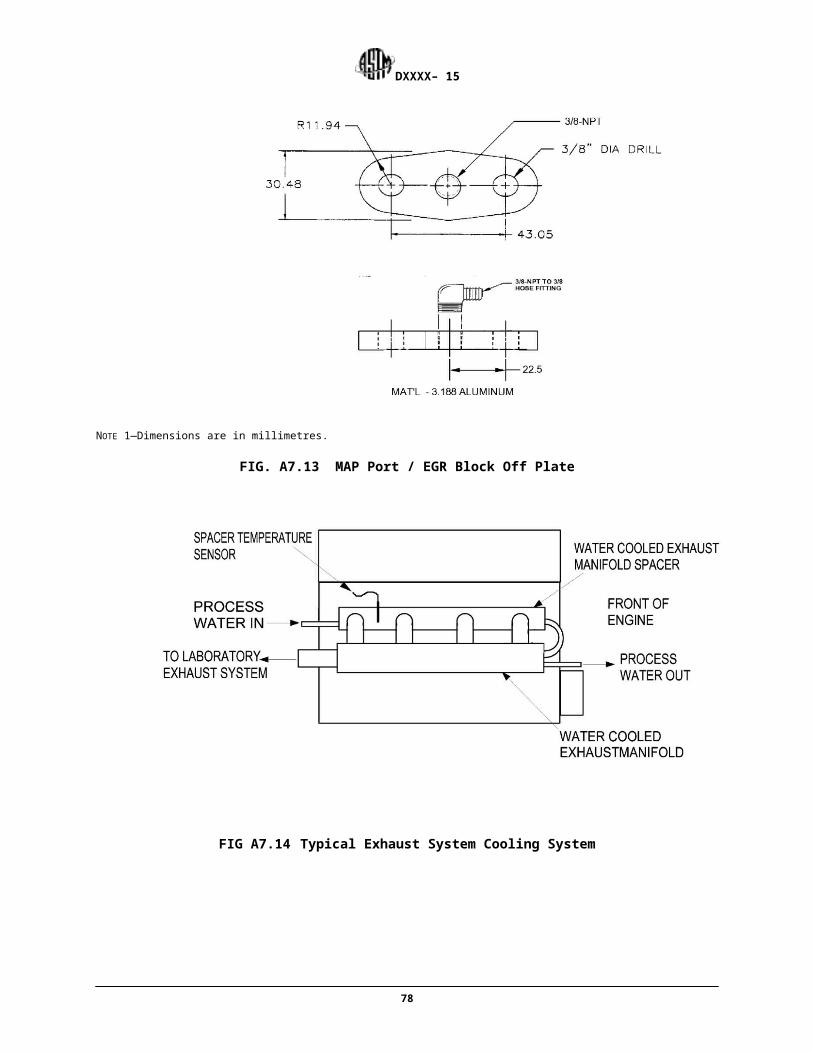
DXXXX– 15
78
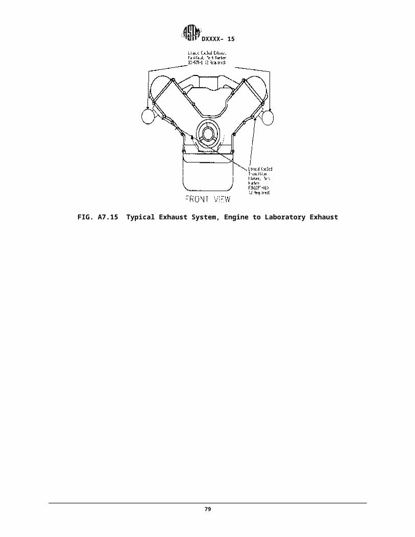
DXXXX– 15
FIG. A15.1 Sludge Rating of Left Rocker Cover
79

DXXXX– 15
FIG. A15.2 Sludge Rating of Right Rocker Cover
FIG. A15.3 Sludge Rating of Left Cam Baffle
80

DXXXX– 15
FIG. A15.4 Sludge Rating of Right Cam Baffle
81
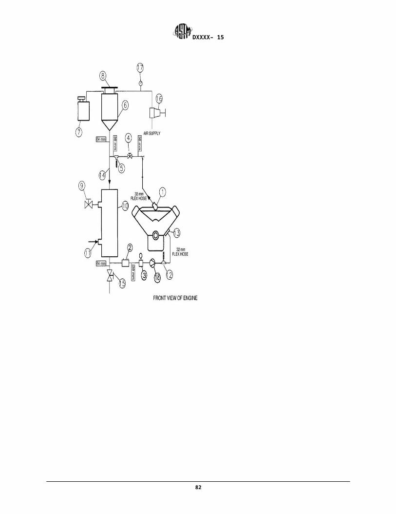
DXXXX– 15
FIG. A15.5 Sludge Rating of Timing Gear Cover
82
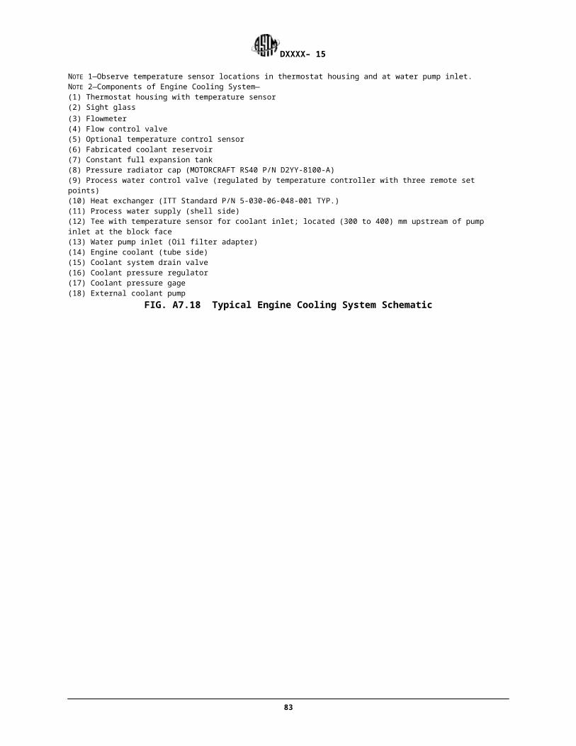
DXXXX– 15
FIG. A15.6 Sludge Rating of Oil Pan Baffles
83
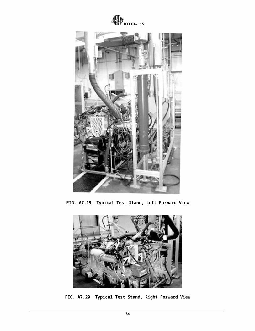
DXXXX– 15
FIG. A15.7 Sludge Rating of Oil Pan
84
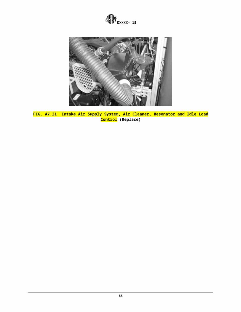
DXXXX– 15
85
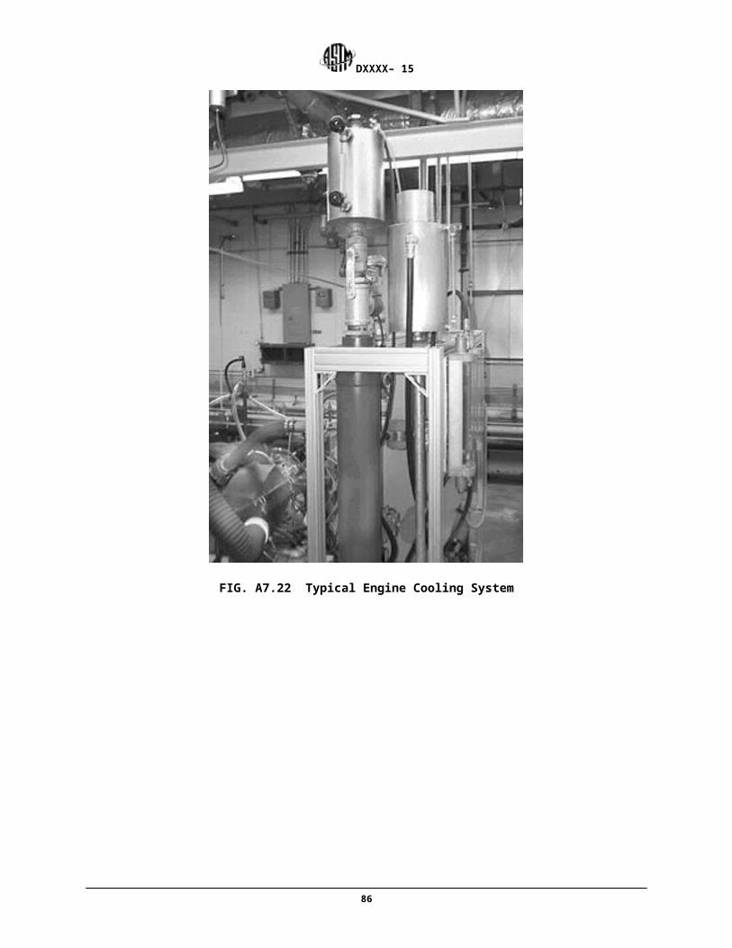
DXXXX– 15
FIG. A15.8 Sludge Rating of Left Valve Deck
86
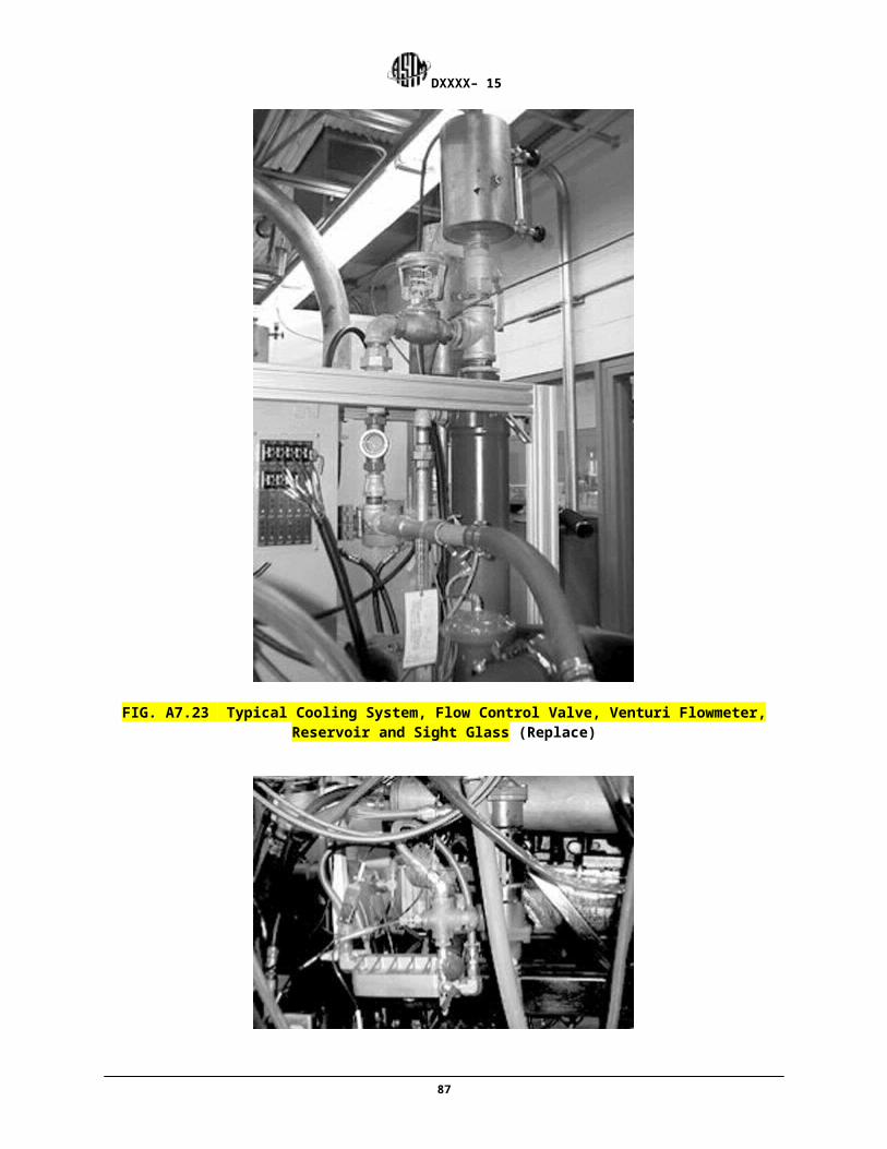
DXXXX– 15
87
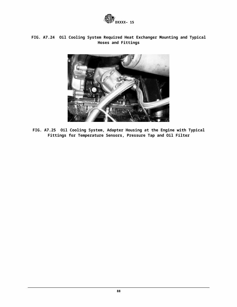
DXXXX– 15
FIG. A15.9 Sludge Rating of Right Valve Deck
88
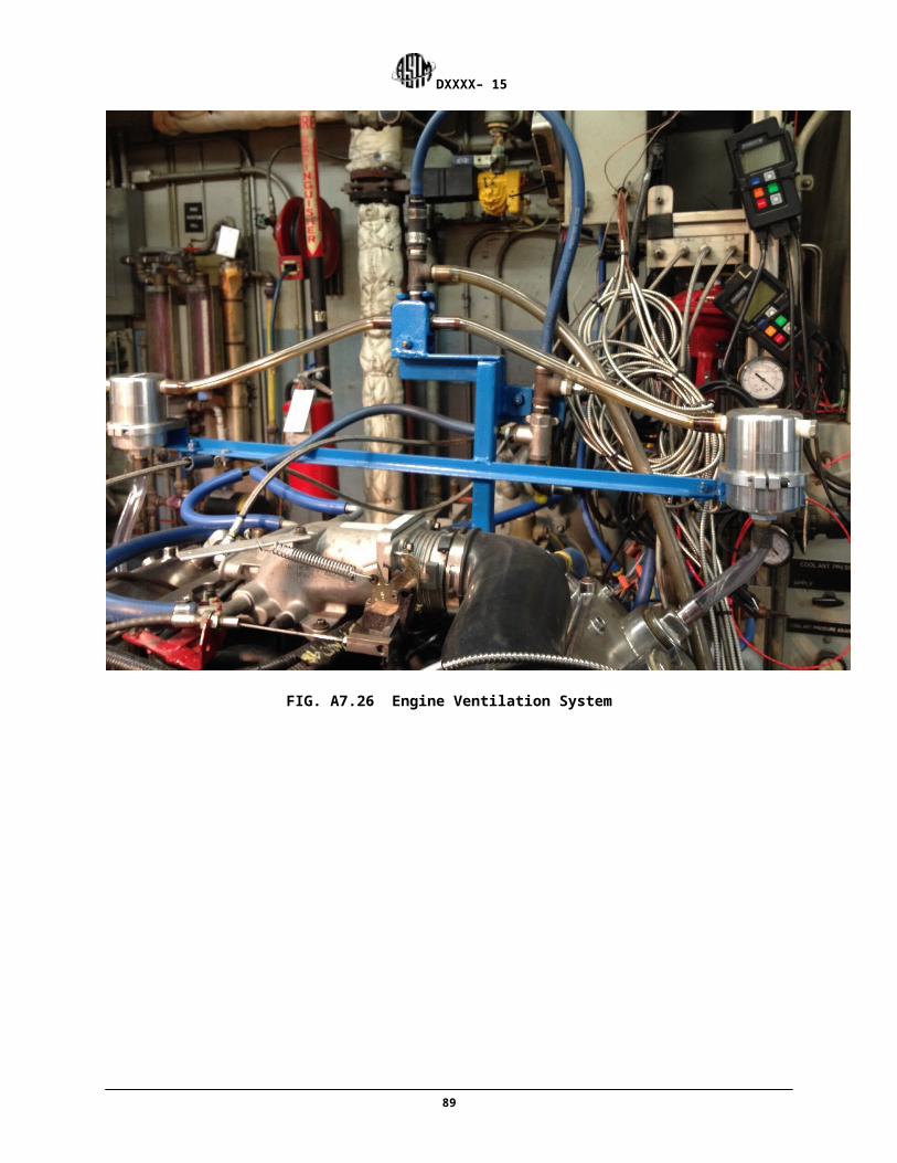
DXXXX– 15
FIG. A15.10 Varnish Rating of Piston Skirts Piston Ring Sticking and Oil Ring Clogging. Oil Screen Percent Plugging
FIG. A15.11 Varnish Rating of Left Camshaft Baffle
89
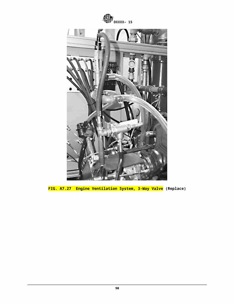
DXXXX– 15
FIG. A15.12 Varnish Rating of Right Camshaft Baffle
90
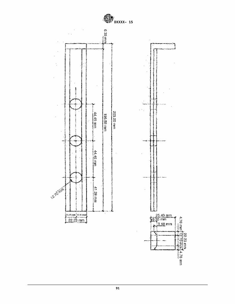
DXXXX– 15
A16. FUEL INJECTOR FLOW MEASUREMENTS
A16.1 Fuel Injector Test Rig—A suitable device capable of accurate, repeatable flow measurement of port fuel injectors is required. This device shall be capable of performing necessary port fuel injector evaluations as outlined below. Since no suitable commercially available apparatus has been identified, design of the test rig is up to the laboratory, Use solvent (see 7.7.1) as the fluid for flow testing injectors. A16.2 Fuel Injectors—Prior to installations, evaluate all injectors (new and used) for spray patterns and flow rate using a suitable apparatus as identified above. The evaluation procedure is outlined in this section. Injectors may be cleaned and reused if the criteria outlined in this section are satisfied.A16.3 Perform a visual inspection of each injector. Ensure that they have been cleaned of all oily deposits. Check O-ring for cracking or tearing and replace as required.A16.4 To remove any assembly residue before flow-testing, flush new injectors for 30 s.A16.5 Using a rig as described, place the injector(s) in the rig and turn on the pressure source to the injector(s). After the pressure source is turned on, the test fluid starts to flow through the injector(s). Maintain the test fluid pressure supplied to the injector(s) during the entire test at 290 kPa ± 3.4 kPa . Maintaining this pressure is critical because a small change in pressure has a dramatic effect on the flow rate and spray pattern. Once pressure is set, zero the volume-measuring device.A16.6 Flow-test each injector for a 60 s period. While the injector is flowing, make a visual observation of the spray pattern quality. The spray pattern should be typical for the make and model of the injector. At the completion of the 60 s period leave pressure on closed injector(s) for at least 30 s. The injector(s) shall not leak or drip. Discard any injector that leaks or drips.A16.7 The acceptable total flow for each injector after the 60 s test shall be 188 mL to 203 mL at 290 kPa ± 3.4 kPa of test fluid pressure. Discard any injector that flows above or below this range.
APPENDIXES
(Nonmandatory Information)
X1. PISTON AND RING MEASUREMENTS RECORD FORMS
X1.1 The necessary engine measurement record forms are shown in Figs. X1.1- X1.3 .
91
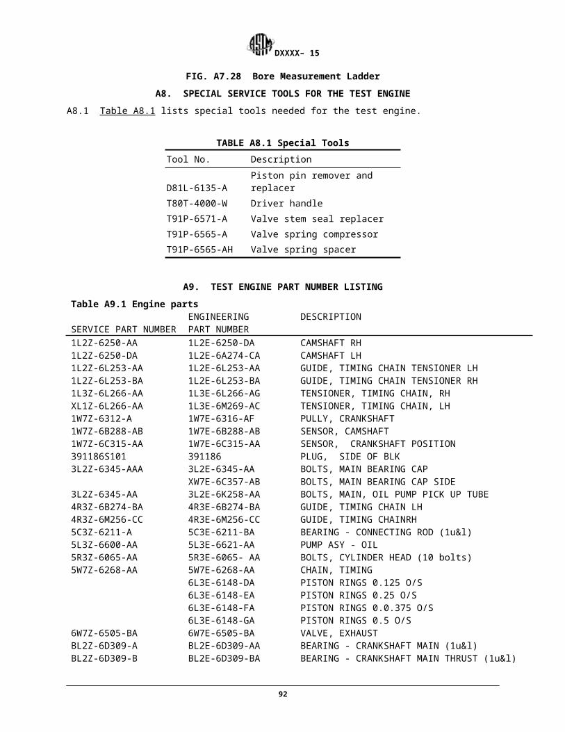
DXXXX– 15
FIG. X1.1 Piston Ring Side Clearance
92
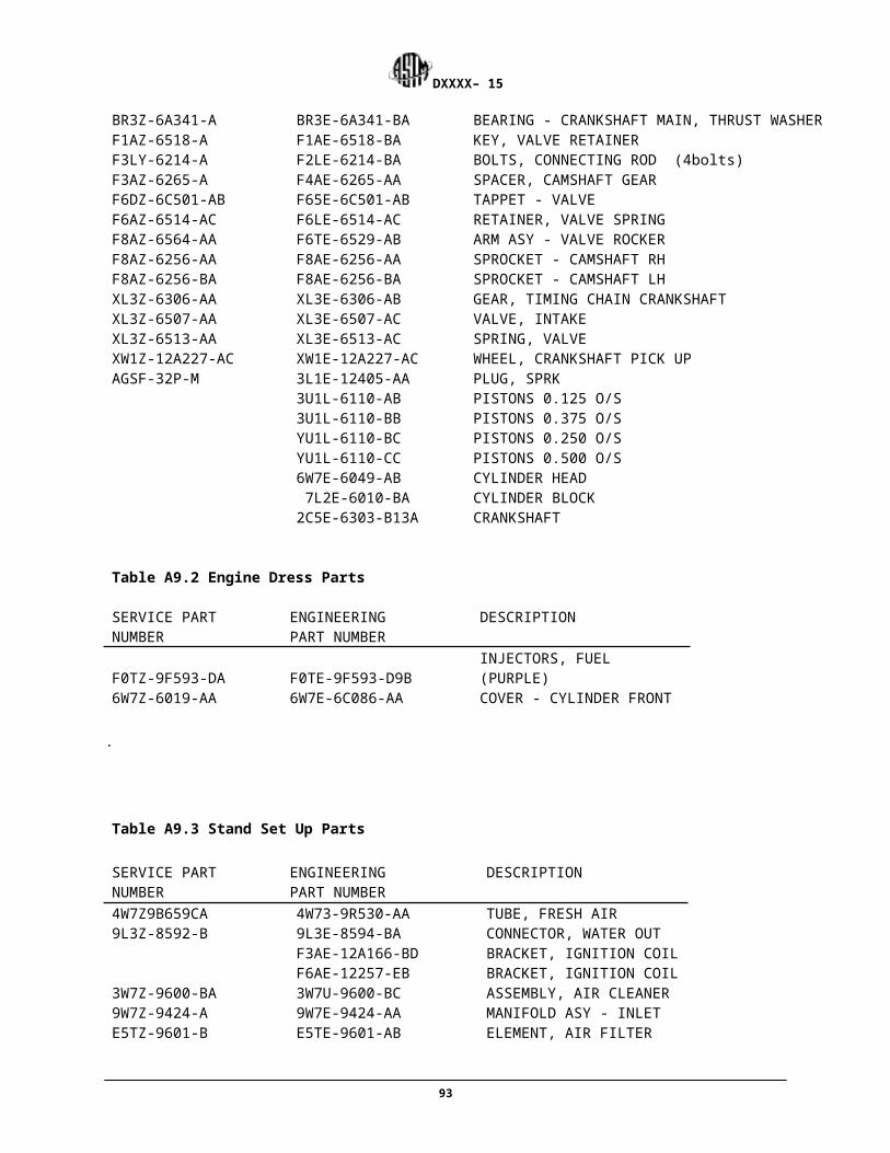
DXXXX– 15
FIG. X1.2 Piston Ring Groove Chamfer and Ring Gap
93
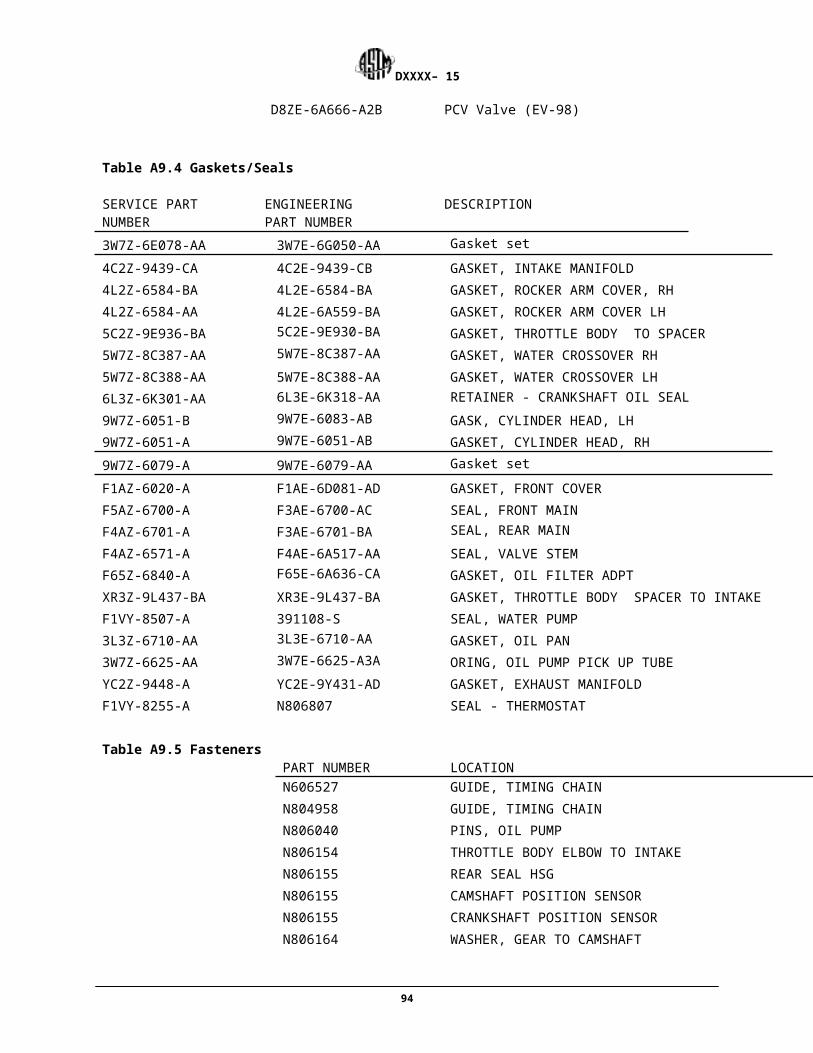
DXXXX– 15
FIG. X1.3 Piston Ring Masses
X2. SOURCES OF MATERIALS AND INFORMATION
X2.1 The following sources are provided for convenience only. This does not represent an exclusive or complete listing of required materials or information sources.
X2.1.1 ASTM Sequence VH Test Parts—ASTM Sequence VH Test Parts can be purchased through Ford Component Sales and Ford or Lincoln dealers.
X2.1.2 ASTM Test Monitoring Center—All communications with the TMC should be directed as follows: ASTM Test Monitoring Center6555 Penn Ave.Pittsburgh, PA 15206-4489X2.1.3 Test Sponsor—All communications with the test sponsor (Ford Motor Co.) should be directed as follows: Ford Motor Co.1800 Fairlane Drive.Room 410Allen Park, Mi 48101
94
DXXXX– 15
X2.1.4 Aeroquip Hose and Fittings—Aeroquip hose and fittings can be obtained from the following supplier: Aeroquip Corp.1225 W. MainVan Wert, OH 45891X2.1.5 Fuel Information and Availability—General information concerning VH fuel, including availability, can
be obtained from the following: Haltermann SolutionsPO Box 429Channelview, TX 79530-0429X2.1.6 Engine Coolant Flowmeter— is available from the following supplier:Micro Motion Corp.7070 Winchester CircleBoulder, CO 80301X2.1.7 Intake-Air Humidity Instruments—The Alnor Dewpointer, EG & G, Foxboro, Hy-Cal, General Eastern
and Protimeter dewpoint meters are suitable for measurement of the intake-air specific humidity.X2.1.8 Blowby Flow Rate Orifice—Information concerning the blowby flow rate orifice meter is available from
the following: AVL
X2.1.9 Heat Exchangers—ITT Standard Heat Exchangers can be obtained from the following supplier: Kinetics Engineering Corp.2055 Silber Road, Suite 101Houston, TX 77055X2.1.10 Fuel Flow Measurement—Mass fuel flowmeters are available from the following supplier: Micro Motion Corp.7070 Winchester CircleBoulder, CO 80301X2.1.11 Various Materials—RAC kits, camshaft baffles, oil filter adapters, flywheel and various other test stand
parts and component calibration devices utilized in this test method are available from the following supplier: OH Technologies9300 Progress Pkwy.Mentor, OH 44060X2.1.12 Parts Washer and Chemicals—A dishwasher type parts cleaner and associated chemicals can be
obtained from the following supplier: Better Engineering Manufacturing8361 Town Court CenterBaltimore, MD 21236-4964
Ultrasonic cleanerPurvis Industries, 10500 North Stemmons Freeway, Dallas, TX 75220.
X2.1.13 Crankcase and Intake—Air Pressure Gages—Gages are available from the following supplier: Dwyer Instrument Co.Junction of Indiana State Highway 212 and U.S. Highway 12P.O. Box 373Michigan City, IN 46360X2.1.14 RAC Coolant—Pencool 2000 Engine Cooling System Treatment is available from the following
supplier: Penray Cos., Inc., 1801 Estes Ave., Elk Grove, IL 60007X2.1.15 Lubricants—EF-411 are available from local distributors of Mobil products.X2.1.16 Connecting Rod Heater—The Sunnen Model CRH-50 connecting rod heater is available from the
95
DXXXX– 15
following supplier: Sunnen Inc.7910 ManchesterSt. Louis, MO 63143X2.1.17 Tygon Hose—Tygon hose is available through local Cadillac Plastic Co. distributors or the following
supplier: The Norton Co.12 East AvenueTallmadge, OH 44278X2.1.18 Rating Lamps—Suitable rating lamps are available from the following supplier: Dazor Manufacturing Corp.4455 Duncan Ave.St. Louis, MO 63110X2.1.19 Special Tools for the Test Engine—Special tools to facilitate assembly and disassembly of the engine are
available from the following supplier: Owatonna Tool Co.2013 4th St.NW Owatonna, MN 55060
X2.1.20 FlywheelFord Racing Flywheel #M-6375-D46 is available from the following supplier:Ford Racing Performance PartsP.O. Box 490Dearborn, MI 48121
OHT Flywheel is available from the following supplier: OH Technologies9300 Progress Pkwy.Mentor, OH 44060
X2.1.21 Coolant Pump Variable Frequency Drive is available from the following supplier:
ASTM International takes no position respecting the validity of any patent rights asserted in connection with any item mentioned in this standard. Users of this standard are expressly advised that determination of the validity of any such patent rights, and the risk of infringement of such rights, are entirely their own responsibility.
This standard is subject to revision at any time by the responsible technical committee and must be reviewed every five years and if not revised, either reapproved or withdrawn. Your comments are invited either for revision of this standard or for additional standards and should be addressed to ASTM International Headquarters. Your comments will receive careful consideration at a meeting of the responsible technical committee, which you may attend. If you feel that your comments have not received a fair hearing you should make your views known to the ASTM Committee on Standards, at the address shown below.
This standard is copyrighted by ASTM International, 100 Barr Harbor Drive, PO Box C700, West Conshohocken, PA 19428-2959, United States. Individual reprints (single or multiple copies) of this standard may be obtained by contacting ASTM at the above address or at 610-832-9585 (phone), 610-832-9555 (fax), or [email protected] (e-mail); or through the ASTM website (www.astm.org). Permission rights to photocopy the standard may also be secured from the ASTM website (www.astm.org/COPYRIGHT/).
96