Embed Size (px)
Citation preview

VIKING PUMP • A Unit of IDEX Corporation • Cedar Falls, IA ©2006
Section 210Page 210.1Issue F
SERIES 724 AND 4724VIKING® HEAVY DUTY ALLOY PUMPS
FEATURES
① Pressure Range
200 PSI (14 BAR) for 100 SSU (21 cSt) and above(Small Pumps—“F”, “FH” and “G” sizes)150 PSI (10 BAR) for 2500 SSU (550 cSt) and above(Large Pumps—“H” and larger sizes)
100 PSI (7 BAR) for 38 to 100 SSU (4 to 21 cSt)(Small Pumps—“F”, “FH” and “G” sizes)50 PSI (3 BAR) for 38 to 100 SSU (4 to 21 cSt)(Large Pumps—“H” and larger sizes)
① Temperature Range ➂ -120°F. to +500°F. (-84°F. to +260°F.)
① Viscosity Range 38 SSU to 2,000,000 SSU (4 to 440,000 cSt)
② G.P.M. 1½-3-5-10-20-35-50-90-110 (m³/hr .3-.7-1-2-5-8-11-20-25)
(Nominal Rating)
INTEGRAL THRUST BEARING
The integral thrust bearing on the series 724 and 4724 alloy pumps makes possible outstanding perfor-mance on heavy-duty applications. The positive-lock thrust control allows for accurate axial positioning of rotor and shaft.
COMPLETE JACKETING(6 large size pumps)
Shaded area above shows complete jacketed areas for maintaining uniform temperature, hot or cold, surrounding packing or mechanical seal area as well as the back and front area of pump. Jacketed head plate available on request.
NO REDUCTION IN SPEED REQUIRED
The three small sizes of alloy pumps can be operated at full motor speeds. This means a saving in speed reduction equipment. Larger sizes can also be operated at full catalog speed. See units on following pages (Section 210).
ALL PARTS CONTACTING LIQUID ARE OF ALLOY
CONSTRUCTION(All Sizes)
(Large size illustrated)All parts contacting liquid being pumped are of alloy construction. Mounting bracket is cast iron.
The 724 and 4724 Series Heavy-Duty line of 316 Stainless Steel pumps feature the foot type bracket with rotor thrust control. All wetted parts are 316 Stainless Steel. The three smaller pumps include opposite port casings, others are right angle port construction. All have revolvable casings for handy port selection and choice of either packing or mechanical seal.
The small pumps are especially useful in pilot plant service, small metering applications, accurate chemi-cal additive processing, pumping of pharmaceuticals in small capacities and for feed and product pumps on evaporators and distillation systems. The six larger sizes meet the needs of moving corrosive liquids when greater capacities are needed in chemical and other processing plants.
In placing orders for 724 and 4724 Series pumps, please furnish the following information:1. Liquid pumped 4. Temperature of Liquid2. Viscosity of 5. Capacity of Pump liquid, S.S.U. 6. Suction lift or head3. Specific Gravity 7. Discharge Pressure① See following pages or consult factory for specific recommendations on individual
pump models or sizes.② Nominal capacities based on handling thin liquids.③ 300°F. maximum for small pumps; “F” , “FH” & “G”.
SERIES 4724 Cutaway ViewMechanical Seal, 1½, 3 and 5 GPM Sizes
SERIES 4724 Cutaway ViewMechanical Seal, 10 to 110 GPM Sizes
Metric conversions are based on US measurements and rounded to the nearest whole number.

VIKING PUMP • A Unit of IDEX Corporation • Cedar Falls, IA ©2006
SERIES 724 AND 4724VIKING® HEAVY DUTY ALLOY PUMPS
UNMOUNTED PUMPS
① Relief valve not available on “F” and “FH” sizes.② For mechanical seal pumps on applications with viscosities above 25,000 SSU
(5,500 cSt), provide details for recommendation.③ Ports are suitable for use with 150# ANSI companion flanges or flanged fittings. All
others tapped for standard pipe.④ Standard seal can be used from 0°F. to +450°F. With special construction, temp-
eratures from -120°F. to +500°F. can be handled with “H” size and larger pumps.
⑤ For handling liquids less than 38 SSU (4 cSt), special construction features may be required. Provide details for recommendations.
⑥ Cast iron jacketed head plate available for “G” size and larger. Relief valve cannot be used on head of pump with jacketed head plate.
⑦ Idler pin on “F” and “FH” size is stellite.Note: Heavy-Duty Universal Seal pumps are also available in 316 Stainless Steel construction; “Q” size operating up to 350 RPM, “M” and “N” sizes to 280 RPM and “R” size to 190 RPM. Refer to catalog section 630.
SERIES 724 and 4724 Pumps“F”, “FH” and “G” Sizes
SERIES 724 and 4724 Pumps“H” through “LL” Sizes
CONSTRUCTION—724 AND 4724 SERIES (“F” THROUGH “LL” SIZES)
SPECIFICATIONS — UNMOUNTED PUMPS
PumpConstruction Casing Head Bracket Rotor Idler
RotorShaft
⑦ IdlerPin Bushings
④ Shaft Sealing① InternalRelief ValvePacked
④Mechanical Seal
316Stainless
StainlessSteel
StainlessSteel Iron Stainless
SteelStainless
SteelStainless
Steel
Coated Stainless
Steel
CarbonGraphite Standard
Stainless Steel, PTFE Carbon Graphite and
Stellite
StainlessSteel
ModelNumber
PortSize
NominalPump Rating
Motor HP Re-quired at Rated Speed Pumping 100 SSU Liquid
MaximumHydro- static
Pressure
④ Maximum Temperature
°F. (°C.)
Maximum Recommended Discharge Pressure PSIG
⑥ Maximum Temperature Pressureof Fluids In Jackets
ApproximateShippingWeight
With Valve⑤ 38to
100SSU
100to
2500SSU
2500SSUandUp
Steam (Sat) Heat Transfer Oil
Temp.°F. (°C.)
PressurePSIG (BAR)
Temp.°F. (°C.)
PressurePSIG (BAR)Packed
② Mech.Seal Inches
GPM (m³/hr) RPM
50 PSI (3 BAR)
100 PSI (7 BAR)
PSIG (BAR) Packed
Mech.Seal Pounds (KG)
F724 F4724 ½ 1½ (.3) 1800 ¼ ¼ 400 (28) 300 (149) 300 (149) 100 200 200 . . . . . . . . . . . . . . . . ① 11 (5)FH724 FH4724 ¾ 3 (.7) 1800 ¼ ⅓ 400 (28) 300 (149) 300 (149) 100 200 200 . . . . . . . . . . . . . . . . ① 12 (5.5)G724 G4724 1 5 (1) 1200 ½ 1 400 (28) 300 (149) 300 (149) 100 200 200 . . . . . . . . . . . . . . . . 14 (6)H724 H4724 1½ 10 (2) 1200 ¾ 1½ 400 (28) 375 (190) 375 (190) 50 100 150 365 (185) 150 (10) 450 (232) 150 (10) 48 (22)
HL724 HL4724 1½ 20 (5) 1200 1 2 400 (28) 375 (190) 375 (190) 50 100 150 365 (185) 150 (10) 450 (232) 150 (10) 50 (23)K724 K4724 2 45 (10) 520 2 5 400 (28) 350 (175) 350 (175) 50 100 150 365 (185) 150 (10) 450 (232) 150 (10) 125 (57)
KK724 KK4724 2 65 (15) 520 3 5 400 (28) 350 (175) 350 (175) 50 100 150 365 (185) 150 (10) 450 (232) 150 (10) 130 (59)L724 L4724 2 90 (20) 420 5 10 400 (28) 350 (175) 350 (175) 50 100 150 365 (185) 150 (10) 450 (232) 150 (10) 170 (77)
LQ724 LQ4724 ③ 2½ 90 (20) 420 5 10 400 (28) 350 (175) 350 (175) 50 100 150 365 (185) 150 (10) 450 (232) 150 (10) 205 (93)LL724 LL4724 ③ 3 110 (25) 420 5 10 400 (28) 350 (175) 350 (175) 50 100 150 365 (185) 150 (10) 450 (232) 150 (10) 240 (109)
All 724 and 4724 Series Stainless Steel pumps of “G” size and larger are standard with integral stainless steel valve on pump head. Pumps of “G” size and larger can also be equipped with cast iron jacketed head plate if desired. Combination of plate and valve not available.
Contact factory for optional alloy materials.
Dimensions for Unmounted Pumps—See page 210.7.Performance Data for Unmounted Pumps—See Pages 210.17 thru 210.34.
Metric conversions are based on US measurements and rounded to the nearest whole number.
Section 210Page 210.2Issue G

VIKING PUMP • A Unit of IDEX Corporation • Cedar Falls, IA ©2006
Section 210Page 210.3Issue F
SERIES 724 AND 4724VIKING® HEAVY DUTY ALLOY PUMPS
UNMOUNTED PUMPS VIKING HELICAL GEAR REDUCER UNITS (“R” DRIVE)
① For mechanical seal pumps on applications with viscosities above 25,000 SSU (5,500 cSt), provide details for recommendation.
② Ports are suitable for use with 150# ANSI companion flanges or flanged fittings. All others tapped for standard pipe.
③ With special construction, temperatures to 500°F. can be handled.④ For handling liquids less than 38 SSU (4 cSt), special construction features may
be required. Provide details for recommendations.⑤ Jacketed head plate available. Relief valve cannot be used on head of pump with
jacketed head plate.⑥ Capacities are based on 100 SSU liquid and 10” Mercury Vacuum.⑦ Not available with “A” size reducer.
SERIES 724 AND 4724
PUMPSwith “R” Drive“B” Reducer
Viking 724 and 4724 Series pumps are available with rugged, compact and exceptionally quiet type “A” and “B” helical gear reducers, all mounted on formed steel bases with motors. Using “A” reducers with two size pumps, “H” and “HL”, and three gear ratios from 2.76 to 1; to 4.17 to 1 and with 1200 or 1800 RPM motors, a capacity range to 17 GPM can be obtained. Using “B” reducers with four size pumps, “K” through “LL”, and eight gear ratios from 1.87 to 1; 7.65 to 1 and with 1200 or 1800 RPM motors, a capacity range to 103 GPM can be obtained.Dimensions for “R” Drive Units-See Page 210.8.Performance Data for “R” Drive Units-See Pages 210.21thru 210.34.
SIZE “A” REDUCER SPECIFICATIONS AND PUMP CAPACITY TABLE
MotorRPM
ReducerRatio
MaximumReducer
HPPumpRPM
Pump Models and Capacity ⑥ GPMWith Size “A” Reducer
H724R HL724R50 PSI
(3 BAR)100 PSI (7 BAR)
50 PSI (3 BAR)
100 PSI (7 BAR)
18002.76 to 1 5 640 5.4 4.9 10.5 103.43 to 1 5 520 4.3 3.8 8.2 7.84.17 to 1 3 420 3.4 3.0 6.5 6.1
12002.76 to 1 3 420 3.4 2.9 6.5 6.13.43 to 1 3 350 2.8 2.3 5.1 4.84.17 to 1 2 280 2.1 1.7 3.9 3.5
SIZE “B” HELICAL REDUCER SPECIFICATIONS AND PUMP CAPACITY TABLE
MotorRPM
ReducerRatio
MaximumReducer
HPPumpRPM
Pump Models and Capacity ⑦ GPM with Size “B” Reducer
K724R orK4724R
KK724R orKK4724R
L724R orL4724R
LQ724R orLQ4724R
LL724R orLL4724R
50 PSI (3 BAR)
100 PSI (7 BAR)
50 PSI (3 BAR)
100 PSI (7 BAR)
50 PSI (3 BAR)
100 PSI (7 BAR)
50 PSI (3 BAR)
100 PSI (7 BAR)
50 PSI (3 BAR)
100 PSI (7 BAR)
1800
4.19:1 10 420 37 34 52 50 86 82 86 82 107 1035.06:1 10 350 30 27 43 41 70 67 70 67 88 84
6.27:1 7½ 280 23 20 33 31 55 51 55 51 68 647.65:1 5 230 18 15 27 25 44 40 44 40 55 51
1200
2.76:1 10 420 37 34 52 50 86 82 86 82 107 1033.40:1 10 350 30 27 43 41 70 67 70 67 88 84
4.19:1 7½ 280 23 20 33 31 55 51 55 51 68 64
5.06:1 7½ 230 18 15 27 25 44 40 44 40 55 51
6.27:1 5 190 14 11 22 20 36 32 36 32 45 407.65:1 5 155 11 8 17 15 27 24 27 24 36 31
SPECIFICATIONS - “R” DRIVE UNITS
ModelNumber
Type of Reducer
PortSize
NominalPump Rating
Motor HPRequired AtRated Speed
Pumping100 SSU Liquid
MaximumHydrostatic
Pressure
③ Maximum
Temperature°F. (°C.)
Maximum Recommended
Discharge PressurePSIG
⑤ Maximum TemperaturePressure of Fluids
In Jackets
ApproximateShipping Weight
With Valve724 & 4724
SeriesSteam (Sat)Heat Transfer
Oil④ 38to
100SSU
100to
2500SSU
2500SSUandUp
Temp.°F. (°C.)
PressurePSIG (BAR)
Temp.°F. (°C.)
PressurePSIG (BAR)Packed
① Mech. Seal Inches
GPM (m³/hr) RPM
50 PSI (3 BAR)
100 PSI (7 BAR)
PSIG (BAR) Packed
Mech.Seal
(Less Power)Pounds (KG)
H724R H4724R A 1½ 6 (1.5) 640 ½ ¾ 400 (28) 375 (190) 375 (190) 50 100 150 365 (185) 150 (10) 450 (232) 150 (10) 125 (57)
HL724R HL4724R A 1½ 11 (3) 640 ½ 1 400 (28) 375 (190) 375 (190) 50 100 150 365 (185) 150 (10) 450 (232) 150 (10) 130 (59)
K724R K4724R B 2 45 (10) 520 2 5 400 (28) 350 (175) 350 (175) 50 100 150 365 (185) 150 (10) 450 (232) 150 (10) 340 (154)
KK724R KK4724R B 2 65 (15) 520 3 5 400 (28) 350 (175) 350 (175) 50 100 150 365 (185) 150 (10) 450 (232) 150 (10) 345 (157)
L724R L4724R B 2 90 (20) 420 5 10 400 (28) 350 (175) 350 (175) 50 100 150 365 (185) 150 (10) 450 (232) 150 (10) 385 (175)
LQ724R LQ4724R B ② 2½ 90 (20) 420 5 10 400 (28) 350 (175) 350 (175) 50 100 150 365 (185) 150 (10) 450 (232) 150 (10) 420 (191)LL724R LL4724R B ② 3 110 (25) 420 5 10 400 (28) 350 (175) 350 (175) 50 100 150 365 (185) 150 (10) 450 (232) 150 (10) 455 (207)
Metric conversions are based on US measurements and rounded to the nearest whole number.
Note: For pump speed of 520 RPM refer to Catalog Section 610 page 5 or Electric Performance Curve generator program.

VIKING PUMP • A Unit of IDEX Corporation • Cedar Falls, IA ©2006
Section 210Page 210.4Issue F
SERIES 724 AND 4724VIKING® HEAVY DUTY ALLOY PUMPS
① For mechanical seal pumps on applications with viscosities above 25,000 SSU (5,500 cSt), provide details for recommendation.
② Ports are suitable for use with 150# ANSI companion flanges or flanged fittings. All others tapped for standard pipe.
③ With special construction, temperatures to 500°F. can be handled with “H” size
and larger pumps.④ For handling liquids less than 38 SSU (4 cSt), special construction features may be
required. Provide details for recommendations.⑤ Jacketed head plate available for “H” size and larger. Relief valve cannot be used
on head of pump with jacketed head plate.
SPECIFICATIONS—”P” DRIVE UNITS
SERIES 724 and 4724 Pumpswith “P” Drive
Viking “P” Drive Units include “K” through “LL” size 724 and 4724 Stainless Steel pumps mounted on formed steel bases with separate heavy-duty gear reducers. Pumps, reducers and motors are connected through flexible couplings with guard and with separate reducers, eliminating radial load on either pump or motor shafts.Performance Data for “P” Drive Units—See Pages 210.27thru 210.34.
Model NumberPortSize
NominalPumpRating
Motor HP Required at
Rated Speed Pumping 100 SSU Liquid
MaximumHydro-static
Pressure
③ MaximumTemperatureDegrees F.
Maximum Recommended
Discharge Pressure PSIG
⑤ Maximum TemperaturePressure of Fluids
In Jackets
ApproximateShipping Weight
With Valve724 & 4724
SeriesSteam (Sat)Heat Transfer
Oil④ 38to
100SSU
100to
2500SSU
2500SSUandUp
Temp.°F. (°C.)
PressurePSIG (BAR)
Temp.°F. (°C.)
PressurePSIG (BAR)
Less Reducerand Power Lbs. (KG)Packed
① Mech.Seal Inches
GPM (m³/hr) RPM
50 PSI (3 BAR)
100 PSI (7 BAR)
PSIG (BAR) Packed
Mech.Seal
K724P K4724P 2 45 (10) 520 2 5 400 (28) 350 (175) 350 (175) 50 100 150 365 (185) 150 (10) 450 (232) 150 (10) 363 (165)
KK724P KK4724P 2 65 (15) 520 3 5 400 (28) 350 (175) 350 (175) 50 100 150 365 (185) 150 (10) 450 (232) 150 (10) 368 (127)
L724P L4724P 2 90 (20) 420 5 10 400 (28) 350 (175) 350 (175) 50 100 150 365 (185) 150 (10) 450 (232) 150 (10) 408 (185)
LQ724P LQ4724P ② 2½ 90 (20) 420 5 10 400 (28) 350 (175) 350 (175) 50 100 150 365 (185) 150 (10) 450 (232) 150 (10) 443 (201)
LL724P LL4724P ② 3 110 (25) 420 5 10 400 (28) 350 (175) 350 (175) 50 400 150 365 (185) 150 (10) 450 (232) 150 (10) 478 (217)
GEAR REDUCTION UNITS (“P” DRIVE)
Metric conversions are based on US measurements and rounded to the nearest whole number.

VIKING PUMP • A Unit of IDEX Corporation • Cedar Falls, IA ©2006
Section 210Page 210.5Issue F
SERIES 724 AND 4724VIKING® HEAVY DUTY ALLOY PUMPS
DIRECT DRIVE UNITS (“D” DRIVE)
① For mechanical seal pumps on applications with viscosities above 25,000 SSU (5,500 cSt), provide details for recommendation.
② Ports are suitable for use with 150# ANSI companion flanges or flanged fittings. All others tapped for standard pipe.
③ With special construction, temperatures to 500°F. can be handled with “H” size and larger pumps.
④ For handling liquids less than 38 SSU (4 cSt), special construction features may be required. Provide details for recommendations.
⑤ Jacketed head plate available for “H” size and larger pumps. Relief valve cannot be used on head of pump with jacketed head plate.
⑥ Not available with valve on head.
SERIES 724 and 4724 Pumpswith “D” Drive
(vari-drive unit)“K” through “LL” Size Pumps
SPECIFICATIONS — “D” DRIVE UNITS
ModelNumber
PortSize
NominalPump Rating
Motor HPRequired at
Rated SpeedPumping
100 SSU Liquid
MaximumHydro-static
Pressure
③ MaximumTemperatureDegrees F.
Maximum Recommended
Discharge PressurePSIG
⑤ Maximum TemperaturePressure of Fluids
In Jackets Approximate Shipping Weight
With Valve724 & 4724
SeriesSteam (Sat)
HeatTransfer Oil
④ 38to
100SSU
100to
2500SSU
2500SSUandUp
Temp. °F. (°C.)
Pressure PSIG (BAR)
Temp. °F. (°C.)
Pressure PSIG (BAR)Packed
① Mech.Seal Inches
GPM (m³/hr) RPM
50 PSI (3 BAR)
100 PSI (7 BAR)
PSIG (BAR) Packed
Mech.Seal
(Less Power)Pounds (KG)
F724D F4724D ½ 1½ (.3) 1800 ¼ ¼ 400 (28) 300 (149) 300 (149) 100 200 200 . . . . . . . . . . . . . . . . ⑥ 32 (14.5)
FH724D FH4724D ¾ 3 (.7) 1800 ¼ ⅓ 400 (28) 300 (149) 300 (149) 100 200 200 . . . . . . . . . . . . . . . . ⑥ 34 (15)
G724D G4724D 1 5 (1) 1200 ½ 1 400 (28) 300 (149) 300 (149) 100 200 200 . . . . . . . . . . . . . . . . 45 (20)
H724D H4724D 1½ 10 (2) 1200 ¾ 1½ 400 (28) 375 (190) 375 (190) 50 100 150 365 (185) 150 (10) 450 (232) 150 (10) 80 (36)
HL724D HL4724D 1½ 20 (5) 1200 1 2 400 (28) 375 (190) 375 (190) 50 100 150 365 (185) 150 (10) 450 (232) 150 (10) 100 (45)
K724D K4724D 2 45 (10) 520 2 5 400 (28) 350 (175) 350 (175) 50 100 150 365 (185) 150 (10) 450 (232) 150 (10) 245 (111)
KK724D KK4724D 2 65 (15) 520 3 5 400 (28) 350 (175) 350 (175) 50 100 150 365 (185) 150 (10) 450 (232) 150 (10) 275 (125)
L724D L4724D 2 90 (20) 420 5 10 400 (28) 350 (175) 350 (175) 50 100 150 365 (185) 150 (10) 450 (232) 150 (10) 335 (152)
LQ724D LQ4724D ② 2½ 90 (20) 420 5 10 400 (28) 350 (175) 350 (175) 50 100 150 365 (185) 150 (10) 450 (232) 150 (10) 370 (168)
LL724D LL4724D ② 3 110 (25) 420 5 10 400 (28) 350 (175) 350 (175) 50 100 150 365 (185) 150 (10) 450 (232) 150 (10) 430 (195)
The “D” drive mounting of 724 and 4724 Series pumps is specially designed for compactness and quiet-ness of operation. In all sizes the pumps and power are mounted on formed steel bases and connected through flexible couplings with guards. As illustrated, the “K” through “LL” sizes direct connect to gearhead motors or
vari-drive units (illustrated) and the “F” and “FH” sizes direct connect to 1800 RPM motors. The “G”, “H” and “HL” pumps are direct connected to 1200 RPM motors.Dimensions for “D” Drive Units—See Pages 210.8 and 210.9.Performance Data for “D” Drive Units—See Pages 210.17thru 210.34.
SERIES 724 and 4724 Pumpswith “D” Drive
“F” through “HL” Size Pumps
Metric conversions are based on US measurements and rounded to the nearest whole number.

VIKING PUMP • A Unit of IDEX Corporation • Cedar Falls, IA ©2006
Section 210Page 210.6Issue F
SERIES 724 AND 4724VIKING® HEAVY DUTY ALLOY PUMPS
V-BELT DRIVE UNITS (“V” DRIVE)
SERIES 724 and 4724 Pumpswith “V” Drive
“F” through “G” Size PumpsSERIES 724 and 4724 Pumps
with “V” Drive,“H” through “LL” Size Pumps
① For mechanical seal pumps on applications with viscosities above 25,000 SSU (5,500 cSt), provide details for recommendation.
② Ports are suitable for use with 150# ANSI companion flanges or flanged fittings. All others tapped for standard pipe.
③ With special construction, temperatures to 500°F. can be handled with “H” size and larger pumps.
④ For handling liquids in less than 38 SSU (4 cSt), special construction features may be required. Provide details for recommendations.
⑤ Jacketed head plate available for “H” size and larger pumps. Relief valve cannot be used on head of pump with jacketed head plate.
⑥ Not available with valve on head.
The “V” Drive Heavy-Duty Units include 724 or 4724 Series pumps mounted on steel bases complete with totally guarded V-belt drive. Drive mounts on end of pump shaft. Slide rails are required on motors. Fur-nished as extra item. For small units, motors usually furnished with slotted feet. Maximum standard reduction
4½ to 1 on “F” thru “HL” size units, 6 to 1 maximum on “K” and larger sizes.Dimensions for “V” Drive Units—See Page 210.10.Performance Data for “V” Drive Units—See Pages 210.13thru 210.30.
Metric conversions are based on US measurements and rounded to the nearest whole number.
SPECIFICATIONS — “V” DRIVE UNITS
ModelNumber
PortSize
NominalPump Rating
Motor HPRequired at
Rated SpeedPumping
100 SSU Liquid
MaximumHydrostatic
Pressure
③ MaximumTemperatureDegrees F.
Maximum Recommended
Discharge PressurePSIG
⑤ Maximum TemperaturePressure of Fluids
In JacketsApproximate
Shipping Weight With
Valve724 & 4724
SeriesSteam (Sat)
HeatTransfer Oil
④ 38to
100SSU
100to
2500SSU
2500SSUandUp
Temp. °F. (°C.)
Pressure PSIG (BAR)
Temp. °F. (°C.)
Pressure PSIG (BAR)Packed
① Mech.Seal Inches
GPM (m³/hr) RPM
50 PSI (3 BAR)
100 PSI (7 BAR)
PSIG (BAR) Packed
Mech.Seal
(Less Power)Pounds (KG)
F724V F4724V ½ 1½ (.3) 1800 ¼ ¼ 400 (28) 300 (149) 300 (149) 100 200 200 . . . . . . . . . . . . . . . . ⑥ 25 (11)
FH724V FH4724V ¾ 3 (.7) 1800 ¼ ⅓ 400 (28) 300 (149) 300 (149) 100 200 200 . . . . . . . . . . . . . . . . ⑥ 27 (12)
G724V G4724V 1 5 (1) 1200 ½ 1 400 (28) 300 (149) 300 (149) 100 200 200 . . . . . . . . . . . . . . . . 53 (24)
H724V H4724V 1½ 10 (2) 1200 ¾ 1½ 400 (28) 375 (190) 375 (190) 50 100 150 365 (185) 150 (10) 450 (232) 150 (10) 119 (54)
HL724V HL4724V 1½ 20 (5) 1200 1 2 400 (28) 375 (190) 375 (190) 50 100 150 365 (185) 150 (10) 450 (232) 150 (10) 129 (59)
K724V K4724V 2 45 (10) 520 2 5 400 (28) 350 (175) 350 (175) 50 100 150 365 (185) 150 (10) 450 (232) 150 (10) 270 (123)
KK724V KK4724V 2 65 (15) 520 3 5 400 (28) 350 (175) 350 (175) 50 100 150 365 (185) 150 (10) 450 (232) 150 (10) 280 (127)
L724V L4724V 2 90 (20) 420 5 10 400 (28) 350 (175) 350 (175) 50 100 150 365 (185) 150 (10) 450 (232) 150 (10) 320 (145)
LQ724V LQ4724V ② 2½ 90 (20) 420 5 10 400 (28) 350 (175) 350 (175) 50 100 150 365 (185) 150 (10) 450 (232) 150 (10) 355 (161)
LL724V LL4724V ② 3 110 (25) 420 5 10 400 (28) 350 (175) 350 (175) 50 100 150 365 (185) 150 (10) 450 (232) 150 (10) 385 (175)

VIKING PUMP • A Unit of IDEX Corporation • Cedar Falls, IA ©2006
Section 210Page 210.7Issue F
SERIES 724 AND 4724VIKING® HEAVY DUTY ALLOY PUMPS
MODEL NO.A B C D E F G H J K L M N O P R S T U V W X Y
PIPE SIZEPACKED MECH. SEAL AA BB
H724 H4724 1½ 3½ 4¾ 3½ 2¾ 2¼ 6¾ 3½ ¹⁵⁄₃₂ 1½ 3¼ 5³⁄₁₆ 1⁵⁄₁₆ ⁹⁄₁₆ ⅝ 10⁵⁄₁₆ 13¼ 1⅝ ¾ ³⁄₁₆ x ³⁄₃₂ 4³⁄₁₆ ⅝ 1¹¹⁄₃₂ ½ ½HL724 HL4724 1½ 3½ 4¾ 3½ 2¾ 2¼ 6¾ 3½ ¹⁵⁄₃₂ 1½ 3¼ 5³⁄₁₆ 1⁵⁄₁₆ ⁹⁄₁₆ ⅝ 10⁵⁄₁₆ 13¼ 1⅝ ¾ ³⁄₁₆ x ³⁄₃₂ 4³⁄₁₆ ⅝ 1¹¹⁄₃₂ ½ ½
K724 K4724 2 5⅛ 8 5½ 4 2¾ 9¼ 4 ¹⁷⁄₃₂ 2 3 9⅜ 1¾ ⅝ ⅝ 14⅛ 18⅛ 2¼ 1⅛ ¼ x ⅛ 6⅞ ⅝ 1½ ¾ 1¼KK724 KK4724 2 5⅛ 8 5½ 4 2¾ 9¼ 4 ¹⁷⁄₃₂ 2 3 9⅜ 1¾ ⅝ ⅝ 14⅛ 18⅛ 2¼ 1⅛ ¼ x ⅛ 6⅞ ⅝ 1½ ¾ 1¼
L724 L4724 2 6½ 10¼ 7 4⅜ 4 10 5⅜ ¹⁷⁄₃₂ 2 3⅜ 9⅛ 1¾ ⅝ ⅝ 15⅝ 19⅝ 2¼ 1⅛ ¼ x ⅛ 7⅛ ⅝ 1¹³⁄₁₆ 1 1LQ724 LQ4724 ① 2½ 7³⁄₁₆ 10¼ 7 4⅜ 4 10 5⅜ ¹⁷⁄₃₂ 2 3⅜ 9⅛ 1¾ ⅝ ⅝ 15⅝ 19⅝ 2¼ 1⅛ ¼ x ⅛ 7⅛ ⅝ 1¹³⁄₁₆ 1 1LL724 LL4724 ① 3 7³⁄₁₆ 10¼ 7 4⅜ 4 10 5⅜ ¹⁷⁄₃₂ 2 3⅜ 9⅛ 2¼ ⅝ ⅝ 15⅝ 20⅛ 2¼ 1⅛ ¼ x ⅛ 7⅝ ⅝ 1¹³⁄₁₆ 1 1
DIMENSIONSThese dimensions are average and not for construction purposes. Certified prints on request.
For specifications, see page 210.2.
DIMENSIONS —724 AND 4724 SERIESUNMOUNTED PUMPS“F”-“FH”-“G” SIZE
For specifications, see page 210.2.
DIMENSIONS —724 AND 4724 SERIESUNMOUNTED PUMPS“H”-“LL” SIZE
① Ports are suitable for use with 150# ANSI (ASA) companion flanges or flanged fittings.
MODEL NUMBER
A B C D E F G H J U L M N OPACKED SEAL
F724 F4724 ½ 2 2½ 2 1¹⁄₁₆ 1 4⅞ 1³⁄₁₆ ¹¹⁄₃₂ ½ 1⅛ 8⁷⁄₁₆ 3 ⁵⁄₁₆FH724 FH4724 ¾ 2 2½ 2 1¹⁄₁₆ 1 4⅞ 1³⁄₁₆ ¹¹⁄₃₂ ½ 1⅛ 8⁷⁄₁₆ 3 ⁵⁄₁₆G724 G4724 1 2½ 3½ 2 1¹⁄₁₆ 1 4⅞ 1³⁄₁₆ ¹¹⁄₃₂ ½ 1⅛ 8⁹⁄₁₆ 3 ⁵⁄₁₆
S
N YRT
K
U
F P
LHM
V-KEYWAY
AA
B
BB
B
D
C
O
EE
G
XJ
A-PIPE SIZE W
VIKING PUMP • A Unit of IDEX Corporation • Cedar Falls, IA ©2006
Section 210Page 210.8Issue F
SERIES 724 AND 4724VIKING® HEAVY DUTY ALLOY PUMPS
For specifications, see page 210.3.
DIMENSIONS —724 AND 4724 SERIES(“R” DRIVE)“H”-“HL” SIZE“A” SIZE REDUCER UNIT
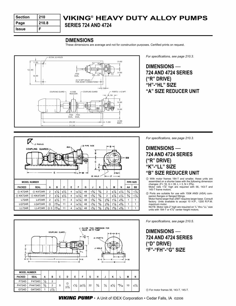
For specifications, see page 210.5.
DIMENSIONS —724 AND 4724 SERIES(“D” DRIVE)“F”-“FH”-“G” SIZE
① For motor frames 56, 143-T, 145-T.
MODEL NUMBER
A B C D E F G H J K L M NPACKED SEAL
F724D F4724D ½ 25
① 3½ 1½ 20½ 22 ¾ ½ 8½ ¹⁵⁄₁₆ 10 4¼FH724D FH4724D ¾ 2
G724D G4724D 1 2½
For specifications, see page 210.3.
DIMENSIONS —724 AND 4724 SERIES(“R” DRIVE)“K”-“LL” SIZE“B” SIZE REDUCER UNIT① With motor frames 184-T and smaller, these units are
assembled on a shorter base with the following dimension changes: (F= 16, G = 39, L = 3, N = 5⅝).Motor rails 1⅞” high are required with 56, 143-T and 145-T frame motors.
② Ports are suitable for use with 150# ANSI (ASA) com-panion flanges or flanged fittings.Motor frame larger than 256T requires larger base. Consult factory. Units available to accept 10 H.P., 1200 R.P.M. maximum motor.NOTE: Motor rails 2” high are required on “L” thru “LL” size units with 184-T or 4½” center height motors.
MODEL NUMBER
A B C E F G J K L M N
PIPE SIZE
PACKED SEAL AA BB
① K724R ① K4724R 2 5⅛ 9½ 4 14¼ 48 1⅜ ⅝ 2 6⅞ 4¼ ¾ 1¼① KK724R ① KK4724R 2 5⅛ 9½ 4 14¼ 48 1⅜ ⅝ 2 6⅞ 4¼ ¾ 1¼
L724R L4724R 2 6½ 11 4 14¼ 48 1⅜ ⅝ 2⅜ 7⅛ 4⅝ 1 1LQ724R LQ4724R ② 7³⁄₁₆ 11 4 14¼ 48 1⅜ ⅝ 2⅜ 7⅛ 4⅝ 1 1LL724R LL4724R ② 3 7³⁄₁₆ 11 4 14¼ 48 1⅜ ⅝ 2⅜ 7⅝ 4⅝ 1 1
DIMENSIONSThese dimensions are average and not for construction purposes. Certified prints on request.

VIKING PUMP • A Unit of IDEX Corporation • Cedar Falls, IA ©2006
Section 210Page 210.9Issue F
SERIES 724 AND 4724VIKING® HEAVY DUTY ALLOY PUMPS
For specifications, see page 210.5.
DIMENSIONS —724 AND 4724 SERIES(“D” DRIVE)“H”-“HL” SIZE
① For motor frames 56, 143T and 145T.② For motor frames 182, 182T, 184 and 184T.③ For motor frames 213 thru 215-T.
For specifications, see page 210.5.
DIMENSIONS —724 AND 4724 SERIES(“D” DRIVE)“K”-“LL” SIZE
① Ports are suitable for use with 150# ANSI (ASA) companion flanges or flanged fittings.
② Varies with gearmotor used.NOTE:Pump units are normally placed on formed steel bases as shown with outside dimensions 4” x 18¾” x 41¾”.
The size of the base is determined by the width of the motor and total length of the unit figured from the back of the motor foot to the end of the pump foot.
For foundation space estimates the following base dimensions can be used:4” x 18¾” x 41¾” (Four ⅝” holes 16” x 39” centers)4” x 17” x 50¾” (Four ⅝” holes 14¼” x 48” centers)6” x 24” x 52” (Four ¹³⁄₁₆” holes 21” x 49” centers)
MODEL NUMBER
A B D E F K L M N S
PIPE SIZE
PACKED SEAL AA BB
H724D OR
HL724D
H4724D OR
HL4724D
1½ 3½ ① 3½ 1½ 20½ ½ 1⅝ 4³⁄₁₆ 8½ 4¼ ½ ¾
1½ 3½ ② 4½ 2¹⁵⁄₁₆ 25 ⁹⁄₁₆ ⁷⁄₁₆ 4³⁄₁₆ 9 4½ ½ ¾
1½ 3½ ③ 5¼ 2¹⁵⁄₁₆ 25 ⁹⁄₁₆ 3¼ 4³⁄₁₆ 9 4½ ½ ¾
MODEL NUMBER
A B②D E F K L M N S
PIPE SIZE
PACKED SEAL AA BB
K724D K4724D 2 5⅛ 4 39 ⅝ 3 6⅞ 16 8 ¾ 1¼
KK724D KK4724D 2 5⅛ 4 39 ⅝ 3 6⅞ 16 8 ¾ 1¼
L724D L4724D 2 6½ 4 39 ⅝ 3⅜ 7⅛ 16 8 1 1
LQ724D LQ4724D ① 2½ 7³⁄₁₆ 4 39 ⅝ 3⅜ 7⅛ 16 8 1 1
LL724D LL4724D ① 3 7³⁄₁₆ 4 39 ⅝ 3⅜ 7⅝ 16 8 1 1
DIMENSIONSThese dimensions are average and not for construction purposes. Certified prints on request.

VIKING PUMP • A Unit of IDEX Corporation • Cedar Falls, IA ©2006
Section 210Page 210.10Issue F
SERIES 724 AND 4724VIKING® HEAVY DUTY ALLOY PUMPS
For specifications, see page 210.6.
DIMENSIONS —724 AND 4724 SERIES(“V” DRIVE)“F”-“FH”-“G” SIZE
MODEL NUMBER
A B C② D E F G H J K L M NPACKED SEAL
F724V F4724V ½ 2
6¼ 20½ 22 8½ 10 1½ ½ 3⅛ 2 3FH724V FH4724V ¾ 2G724V G4724V 1 2½
For specifications, see page 210.6.
DIMENSIONS —724 AND 4724 SERIES(“V” DRIVE)“H”-“LL” SIZE
① Ports are suitable for use with 150# ANSI (ASA) com-panion flanges or flanged fittings.
② Base dimensions correct for all motors.③ Base dimensions correct thru frame 215T motors. Larger
motors require larger base.
MODEL NUMBER
A B C E F G J K L M N
PIPE SIZE
PACKED SEAL AA BB
② H724V H4724V 1½ 3½ 9¼ 1¾ 14¾ 23¾ ¾ ½ 5 4³⁄₁₆ 4¼ ½ ¾② HL724V HL4724V 1½ 3½ 9¼ 1¾ 14¾ 23¾ ¾ ½ 5 4³⁄₁₆ 4¼ ½ ¾③ K724V K4724V 2 5⅛ 3¼ 17 28¾ 1 ½ 2½ 6⅞ 5¼ ¾ 1¼③ KK724V KK4724V 2 5⅛ 3¼ 17 28¾ 1 ½ 2½ 6⅞ 5¼ ¾ 1¼③ L724V L4724V 2 6½ 15⁵⁄₁₆ 3¼ 17 28¾ 1 ½ 2¼ 7⅛ 5¼ 1 1③ LQ724V LQ4724V ① 7³⁄₁₆ 15⁵⁄₁₆ 3¼ 17 28¾ 1 ½ 2¼ 7⅛ 5¼ 1 1③ LL724V LL4724V ① 3 7³⁄₁₆ 15⁵⁄₁₆ 3¼ 17 28¾ 1 ½ 2¼ 7⅝ 5¼ 1 1
NOTE: Base dimension correct for all motors.① Allow 3⅝” for valve on “G” pump.② Varies with motor used.
DIMENSIONSThese dimensions are average and not for construction purposes. Certified prints on request.