Embed Size (px)
Citation preview
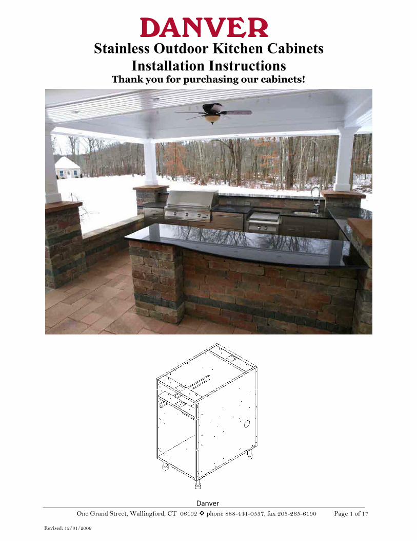
Danver One Grand Street, Wallingford, CT 06492 phone 888-441-0537, fax 203-265-6190 Page 1 of 17
Revised: 12/31/2009
Stainless Outdoor Kitchen Cabinets Installation Instructions
Thank you for purchasing our cabinets!
Danver One Grand Street, Wallingford, CT 06492 phone 888-441-0537, fax 203-265-6190 Page 2 of 17
Revised: 12/31/2009
INSTALLATION TIPS AND PREP Prepare Area for Kitchen: Make sure your landscape area is as level as possible and that there will be minimal additional landscaping to be performed after cabinets are installed.
Notes and Installation Tips: Upon receipt of cabinets:
Carefully review packing list to verify your order has been shipped complete and carefully unpack cabinets making sure not to scratch Stainless Steel fronts and not to lose or misplace any accessories or hardware. Hardware (pulls, hinges, rivets, screws, etc.) is in a small box in each cabinet. Doors are not installed to protect the cabinet sides during shipping. All cabinets will have doors packed separately (drawers ARE shipped installed), some will be in the box with the cabinet and some will be in a separate box (when an accessory is installed). A label will be on each cabinet box with this information. Uninstall shipping brackets from appliance cabinets and reinstall in proper position near the back of those cabinets where they act as counter top supports BEFORE ATTACHING ADDITIONAL CABINETS.
Basic Notes on Installation: Install cabinets in final position. Cabinets are not easy to move after assembly is complete. Install first cabinet at highest point so toe kick area is minimum 4 ½”. Then install adjacent cabinets. This insures that the toe kick will fit under all cabinets without needing to cut it down in the field. DO NOT remove vinyl protective coating until installation is complete. Peel back vinyl covered areas where it will be hard to remove after install (e.g. back and side panels, fillers). Remove all drawers before installation. This will make cabinets easier to lift and install and give access to installation hardware. Squeeze plastic clips under front sides of drawer to release and lift drawers off under mount slides. Install cabinets completely (cabinets screwed together, counter top installed, appliances installed, doors installed, drawers returned to original positions and level is obtained) before attempting to adjust doors or drawers. Cabinets may flex until they are locked into place when screwed to one another. Tighten screws on top rails (if necessary) prior to installation. Attach single cabinets to frame in masonry, stucco, stone or one-piece island installations. 1/8” bumpers are inserted between drawers to protect the drawer heads during shipping. They may be discarded with the protective peel coat. Tools you will need: Power screw gun (#2 Phillips), #2 Phillips head manual screw driver, level, tape measure
Danver One Grand Street, Wallingford, CT 06492 phone 888-441-0537, fax 203-265-6190 Page 3 of 17
Revised: 12/31/2009
ASSEMBLY & INSTALLATION STORAGE CABINET ASSEMBLY
Verify product number(s) on box(es) to order.
Carefully unpack cabinets making sure not to scratch stainless steel fronts. Stainless is protected by a plastic coating that must be removed after setup. All cabinets will have doors packed uninstalled. Those with interchangeable doors (right or left opening) will use the supplied caps to cover holes after the hinge side has been chosen.
1. Remove and check hardware bag/box that contains legs, hinges, hinge plates, screws (#8 (smaller) to install hinge plates to cabinet walls, small countersunk screws to attach hinges to cabinet doors and #10 (larger) for all other assembly and attaching cabinets to one another, screws for pulls), pulls (handles), extra bumpers, plastic edge guard for access holes, hinge hole covers. Also packed with the cabinet is a TOP BRACKET CONNECTOR. Since one top bracket connector is with each cabinet, you will end up with one extra when you finish installation.
2. Remove foam packing material and discard.
3. Remove drawers and accessories that may hinder assembly and store in a safe place.
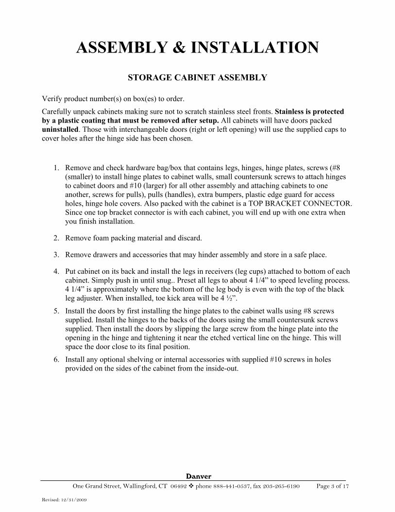
4. Put cabinet on its back and install the legs in receivers (leg cups) attached to bottom of each cabinet. Simply push in until snug.. Preset all legs to about 4 1/4” to speed leveling process. 4 1/4” is approximately where the bottom of the leg body is even with the top of the black leg adjuster. When installed, toe kick area will be 4 ½”.
5. Install the doors by first installing the hinge plates to the cabinet walls using #8 screws supplied. Install the hinges to the backs of the doors using the small countersunk screws supplied. Then install the doors by slipping the large screw from the hinge plate into the opening in the hinge and tightening it near the etched vertical line on the hinge. This will space the door close to its final position.
6. Install any optional shelving or internal accessories with supplied #10 screws in holes provided on the sides of the cabinet from the inside-out.
Danver One Grand Street, Wallingford, CT 06492 phone 888-441-0537, fax 203-265-6190 Page 4 of 17
Revised: 12/31/2009
Toe Kick—install clip with Velcro to
white side
Leg,
Receiver
Use #8 screw;
Vertical alignment
Horizontalalignment
Attachment screw; also
front to back alignment
Foot Installation
Door Installation
Countersunkscrews here;
PVC backer
Danver One Grand Street, Wallingford, CT 06492 phone 888-441-0537, fax 203-265-6190 Page 5 of 17
Revised: 12/31/2009
APPLIANCE AND GRILL CABINET ASSEMBLY
Verify product number(s) on box(es) to order.
Carefully unpack cabinets making sure not to scratch stainless steel fronts. Stainless is protected by a plastic coating that must be removed after setup. All cabinets will have doors packed uninstalled.
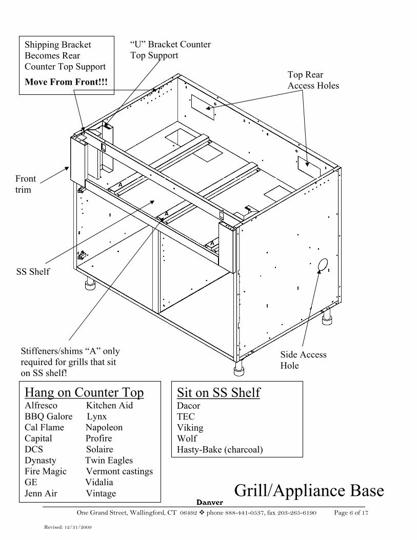
The shipping bracket must be removed and relocated to be the counter top support bracket towards the rear of the cabinet.
1. Remove and check hardware bag/box that contains legs, hinges, hinge plates, screws (#8 (smaller) to install hinge plates to cabinet walls, small countersunk screws to attach hinges to cabinet doors and #10 (larger) for all other assembly and attaching cabinets to one another, screws for pulls), pulls (handles), extra bumpers, plastic edge guard for access holes, hinge hole covers. Also packed with the cabinet is a TOP BRACKET CONNECTOR. Since one top bracket connector is with each cabinet, you will end up with one extra when you finish installation.
2. Remove foam packing material and discard.
3. Remove shipping bracket from front of appliance cabinet and using the same screws,relocate to the back of the unit. This will become the rear counter top support. Its location is dependent upon the depth (front to back) of the grill/appliance, so it is necessary at this point to find the grill manufacturer’s specified depth. Take the manufacturer’s depth and add ½” to the measurement. Then measure from the front, including the door or trim, and locate the pre-drilled holes at that location in the cabinet side walls. Using the original #10 screws, attach the bracket so it is flush with the top of the cabinet.
4. Note on grills that DO NOT hang from counter top: Cabinets designed for appliances that sit on the deck of the cabinets (e.g. Viking, Dacor, etc.) are shipped with spacers to shim the grill to the height of most granite countertops. If the counter is more than 1 ¼” thick, additional shimming must be used (not supplied).
5. Put cabinet on its back and install the legs in receivers (leg cups) attached to bottom of each cabinet. Simply push in until snug.. Preset all legs to about 4 1/4” to speed leveling process. 4 1/4” is approximately where the bottom of the leg body is even with the top of the black leg adjuster. When installed, toe kick area will be 4 ½”.
6. Grill/appliance cabinets come with 2 front counter top supports or “U” brackets. These are installed behind the side trim pieces using #10 screws. They are not interchangeable; align them on the left or right to where the pre-drilled holes match up.
7. Grill/appliance cabinets come with 2 bottom and 4 rear access holes (2 bottom rear and 2 top rear). Gas plumbing is usually run through the holes in the floor of the cabinet and then through the holes in the SS shelf to the fitting on the grill (either left or right side depending on the manufacturer). The plates on the remaining holes may be removed to allow airflow to meet local building codes.
8. Handles are found in the hardware bag (if supplied). Remove the vinyl protective coating prior to installing the handles; then install them using the screws provided.
Danver One Grand Street, Wallingford, CT 06492 phone 888-441-0537, fax 203-265-6190 Page 6 of 17
Revised: 12/31/2009
9.
Grill/Appliance Base
Shipping Bracket Becomes Rear Counter Top SupportMove From Front!!!
Fronttrim
“U” Bracket Counter Top Support
Stiffeners/shims “A” only required for grills that sit on SS shelf!
Hang on Counter TopAlfresco Kitchen Aid BBQ Galore Lynx Cal Flame Napoleon Capital Profire DCS Solaire Dynasty Twin Eagles Fire Magic Vermont castings GE Vidalia Jenn Air Vintage
Sit on SS ShelfDacorTECVikingWolfHasty-Bake (charcoal)
SS Shelf
Top Rear Access Holes
Side Access Hole
Danver One Grand Street, Wallingford, CT 06492 phone 888-441-0537, fax 203-265-6190 Page 7 of 17
Revised: 12/31/2009
CABINET INSTALLATION/JOINING CABINETS
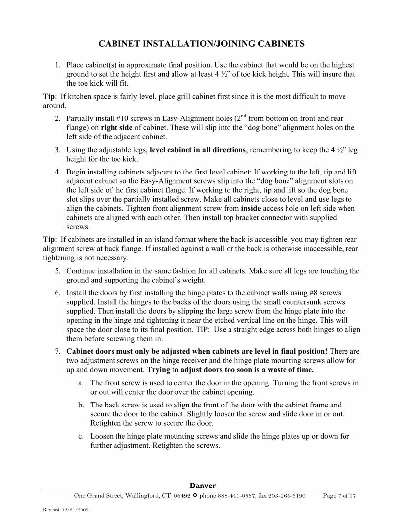
1. Place cabinet(s) in approximate final position. Use the cabinet that would be on the highest ground to set the height first and allow at least 4 ½” of toe kick height. This will insure that the toe kick will fit.
Tip: If kitchen space is fairly level, place grill cabinet first since it is the most difficult to move around.
2. Partially install #10 screws in Easy-Alignment holes (2nd from bottom on front and rear flange) on right side of cabinet. These will slip into the “dog bone” alignment holes on the left side of the adjacent cabinet.
3. Using the adjustable legs, level cabinet in all directions, remembering to keep the 4 ½” leg height for the toe kick.
4. Begin installing cabinets adjacent to the first level cabinet: If working to the left, tip and lift adjacent cabinet so the Easy-Alignment screws slip into the “dog bone” alignment slots on the left side of the first cabinet flange. If working to the right, tip and lift so the dog bone slot slips over the partially installed screw. Make all cabinets close to level and use legs to align the cabinets. Tighten front alignment screw from inside access hole on left side when cabinets are aligned with each other. Then install top bracket connector with supplied screws.
Tip: If cabinets are installed in an island format where the back is accessible, you may tighten rear alignment screw at back flange. If installed against a wall or the back is otherwise inaccessible, rear tightening is not necessary.
5. Continue installation in the same fashion for all cabinets. Make sure all legs are touching the ground and supporting the cabinet’s weight.
6. Install the doors by first installing the hinge plates to the cabinet walls using #8 screws supplied. Install the hinges to the backs of the doors using the small countersunk screws supplied. Then install the doors by slipping the large screw from the hinge plate into the opening in the hinge and tightening it near the etched vertical line on the hinge. This will space the door close to its final position. TIP: Use a straight edge across both hinges to align them before screwing them in.
7. Cabinet doors must only be adjusted when cabinets are level in final position! There are two adjustment screws on the hinge receiver and the hinge plate mounting screws allow for up and down movement. Trying to adjust doors too soon is a waste of time.
a. The front screw is used to center the door in the opening. Turning the front screws in or out will center the door over the cabinet opening.
b. The back screw is used to align the front of the door with the cabinet frame and secure the door to the cabinet. Slightly loosen the screw and slide door in or out. Retighten the screw to secure the door.
c. Loosen the hinge plate mounting screws and slide the hinge plates up or down for further adjustment. Retighten the screws.
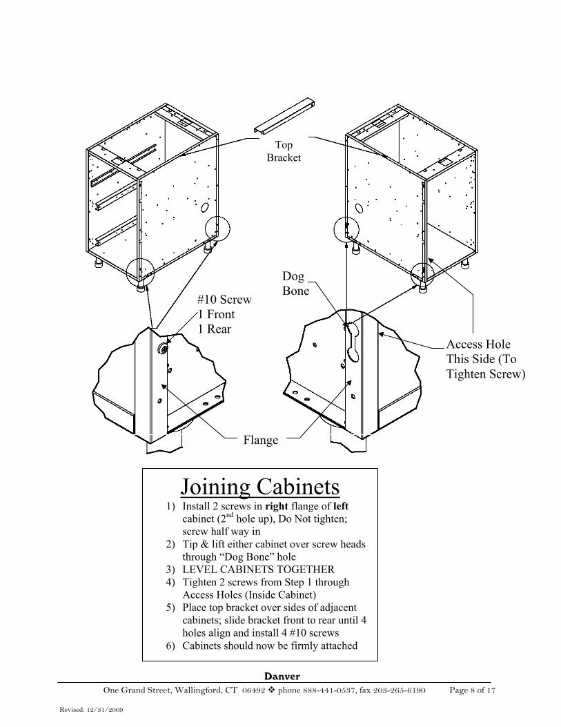
Danver One Grand Street, Wallingford, CT 06492 phone 888-441-0537, fax 203-265-6190 Page 8 of 17
Revised: 12/31/2009
TopBracket
#10 Screw 1 Front 1 Rear
DogBone
Access Hole This Side (To Tighten Screw)
Joining Cabinets1) Install 2 screws in right flange of left
cabinet (2nd hole up), Do Not tighten; screw half way in
2) Tip & lift either cabinet over screw heads through “Dog Bone” hole
3) LEVEL CABINETS TOGETHER 4) Tighten 2 screws from Step 1 through
Access Holes (Inside Cabinet) 5) Place top bracket over sides of adjacent
cabinets; slide bracket front to rear until 4 holes align and install 4 #10 screws
6) Cabinets should now be firmly attached
Flange
Danver One Grand Street, Wallingford, CT 06492 phone 888-441-0537, fax 203-265-6190 Page 9 of 17
Revised: 12/31/2009
BACK, SIDE PANEL AND FILLER INSTALLATION
Back Panels
Optional Back Panels are available for all cabinets. Back panels are ordered based on cabinet size (e.g. OBP18 for an 18” cabinets, OBP24 for a 24” cabinet, etc.). If a cabinet is larger than 30” wide, you will need 2 back panels equal to the length of the cabinet (e.g. two OBP18 for a 36” cabinet, two OBP21 for a 42” cabinet, etc.).
Back Panels for appliance cabinets are made with vents to allow air flow and to keep gas from being entrapped between the back of the cabinet and the back panel. Vented back panels (OBPV) are ordered the same way as non-vented back panels (e.g. OBPV18 for a 18” side burner cabinet, two OBPV31 for a 62” grill cabinet, etc.).
Back panels extend the depth of the cabinets by ¾”!Back panels are designed to fit in the exact width of the cabinet!Side Panels
Optional Side Panels are available for all cabinets in several standard depths. Cabinets are designed to have the seam between the side panels and back panels at the back. So if you are using back panels, you need to order side panels that extend beyond the back of the cabinet by ¾” (e.g. OSP 25 5/8 for 24”D cabinets, OSP28 5/8 for 27”D cabinets and VSP30 5/8” for Viking 29”D cabinets.
If you are installing side panels without back panels (e.g. against a wall) you can order them for the exact depth of the cabinets in which case you need to order lefts and rights. Many customers like to install the cabinet backs away from the wall in which case you can order the larger standard size side panels or custom widths (which include an engineering charge).
Side panels extend the width of the cabinets by ¾”! Side panels are designed to extend to the face of the cabinet door!Galvanized Filler Panels
Many installations call for adhering cement board (e.g. Hardibacker) with stucco or cultured stone directly to the sides of the cabinets. Galvanized filler panels can be installed in the sides and backs of the cabinets to make the walls flush to the flanges. Simply screw the cement board, lath, foam board, etc. to the galvanized filler panels to complete the finished sides and backs.
Galvanized filler panels DO NOT extend the depth or the width of the cabinets!To Install Panels:
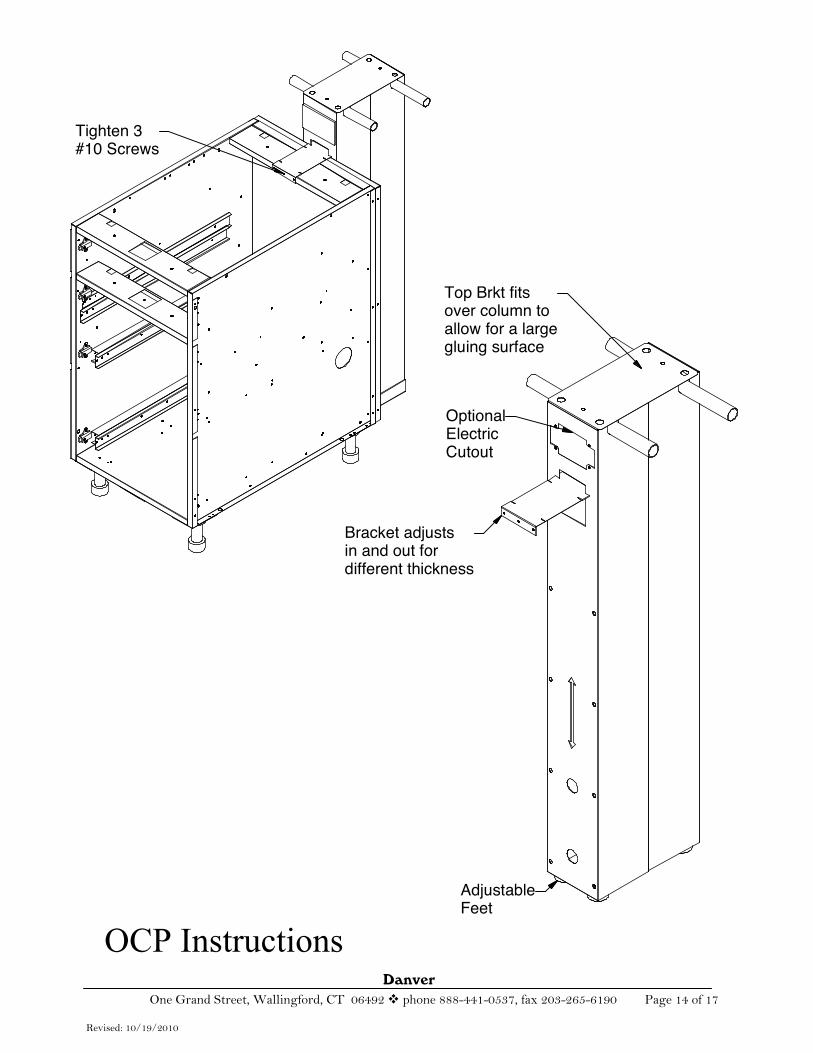
1. Install 2 #10 screws in the bottom two holes of the panel. Screw all the way in. These are only for aligning the panel in the side or back!
2. Align the screw heads on the bottom of the panel from Step 1 with the large hole cutouts in the bottom flange at the side or back of the cabinet. Insert the screw heads into the alignment holes FROM THE TOP and rest the panel on the flange. Push the top of the panel until it rests against the top side or back of the cabinet BELOW THE TOP OF THE FLANGE and align to the obround holes in the cabinet wall. When in position fasten with 2 #10 screws to secure panel from the inside of the cabinet.
Danver One Grand Street, Wallingford, CT 06492 phone 888-441-0537, fax 203-265-6190 Page 10 of 17
Revised: 12/31/2009
Straight Fillers
Front fillers are offered in standard sizes from about 1” to 6+”. They are also sold in custom sizes (with an engineering charge). The designation for a front filler is OFLFxx where the xx is the width of the filler. The front filler design incorporates a small “joggle bend” to provide a proper reveal on either side adjacent to the cabinets or wall. Rear fillers have straight bends and do not provide a reveal. The designation for a rear filler is OFLxx where the xx is the width of the filler.
Front fillers are designed to extend to the face of the cabinet door!1. Partially install 3 #10 screws in the accessory holes in the front flange of the cabinet(s) for
front fillers and in the side of the back panels for rear fillers.
2. Align the front filler to the face of the door and slip the keyholes in the filler over the partially installed screws (Keyhole Alignment Method).Align the rear filler to the back panel and install the same way as the front filler.
3. Tighten screws.
Angle Fillers
Angle fillers are offered standard in 90 degree (OAF90 for front, OAR90 for rear) and 45 degree (OAF45, OAR45) with 4” on either side of the angle. Custom sizes are available (with an engineering charge).
The front angle fillers are installed the same as straight fillers using the Keyhole Alignment Method. The rear angle fillers (OARxx) include an angled post with adjustable leg and 2 panels to fill a corner void where counter top support is required. For rear angle fillers:
1. Partially install 3 #10 screws in the holes on each side of the angled post.
2. Partially install 3 #10 screws in the accessory holes on the rear flange of the cabinet(s) or, if using back panels, in the 3 holes in the side of the back panels installed on the adjacent cabinets.
3. Install the panels using the Keyhole Alignment Method described earlier.
Refrigerator Accessory Panels
Depending on the layout, you may require Danver accessories to complete the installation of refrigerators in the outdoor kitchen.
1. If you are building a freestanding island with Danver back panels, you will need Refrigerator Spacers of the appropriate size to match the refrigerator’s width (ORS15, ORS24, ORS27). These are screwed to the back panels on the adjacent cabinets using the Keyhole Alignment Method. The spacer acts as the back panel behind the refrigerator.
2. If you are installing two refrigeration appliances (e.g. refrigerator and ice maker or freezer or beer dispenser) next to each other in a freestanding island installation, most designers prefer to install a support member between the appliances on which to rest the counter top, and to provide a better visual appearance. A Box Column (OBX--3 7/8” wide and has two leveling legs) of the appropriate depth to match the cabinets is designed for this purpose. It is installed between the two refrigerator spacers at the back using the Keyhole Alignment Method and creates 2 spaces for the appliances.
Danver One Grand Street, Wallingford, CT 06492 phone 888-441-0537, fax 203-265-6190 Page 11 of 17
Revised: 12/31/2009
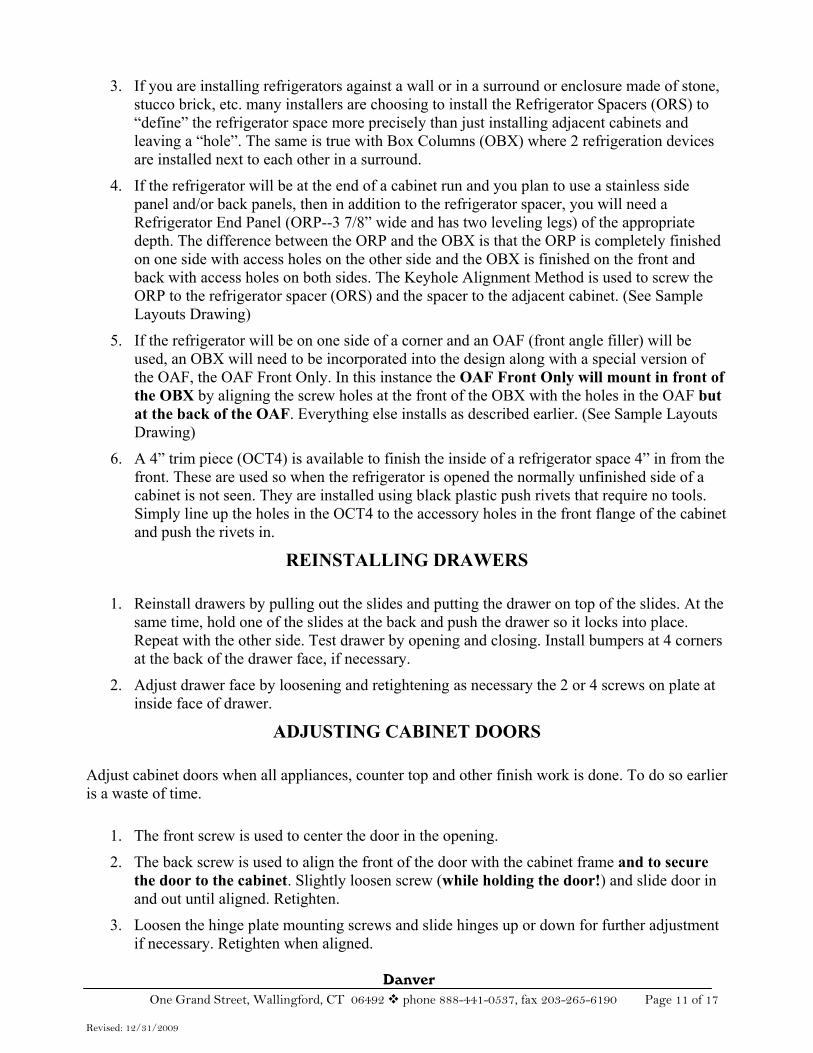
3. If you are installing refrigerators against a wall or in a surround or enclosure made of stone, stucco brick, etc. many installers are choosing to install the Refrigerator Spacers (ORS) to “define” the refrigerator space more precisely than just installing adjacent cabinets and leaving a “hole”. The same is true with Box Columns (OBX) where 2 refrigeration devices are installed next to each other in a surround.
4. If the refrigerator will be at the end of a cabinet run and you plan to use a stainless side panel and/or back panels, then in addition to the refrigerator spacer, you will need a Refrigerator End Panel (ORP--3 7/8” wide and has two leveling legs) of the appropriate depth. The difference between the ORP and the OBX is that the ORP is completely finished on one side with access holes on the other side and the OBX is finished on the front and back with access holes on both sides. The Keyhole Alignment Method is used to screw the ORP to the refrigerator spacer (ORS) and the spacer to the adjacent cabinet. (See Sample Layouts Drawing)
5. If the refrigerator will be on one side of a corner and an OAF (front angle filler) will be used, an OBX will need to be incorporated into the design along with a special version of the OAF, the OAF Front Only. In this instance the OAF Front Only will mount in front of the OBX by aligning the screw holes at the front of the OBX with the holes in the OAF butat the back of the OAF. Everything else installs as described earlier. (See Sample Layouts Drawing)
6. A 4” trim piece (OCT4) is available to finish the inside of a refrigerator space 4” in from the front. These are used so when the refrigerator is opened the normally unfinished side of a cabinet is not seen. They are installed using black plastic push rivets that require no tools. Simply line up the holes in the OCT4 to the accessory holes in the front flange of the cabinet and push the rivets in.
REINSTALLING DRAWERS
1. Reinstall drawers by pulling out the slides and putting the drawer on top of the slides. At the same time, hold one of the slides at the back and push the drawer so it locks into place. Repeat with the other side. Test drawer by opening and closing. Install bumpers at 4 corners at the back of the drawer face, if necessary.
2. Adjust drawer face by loosening and retightening as necessary the 2 or 4 screws on plate at inside face of drawer.
ADJUSTING CABINET DOORS
Adjust cabinet doors when all appliances, counter top and other finish work is done. To do so earlier is a waste of time.
1. The front screw is used to center the door in the opening.
2. The back screw is used to align the front of the door with the cabinet frame and to secure the door to the cabinet. Slightly loosen screw (while holding the door!) and slide door in and out until aligned. Retighten.
3. Loosen the hinge plate mounting screws and slide hinges up or down for further adjustment if necessary. Retighten when aligned.
Danver One Grand Street, Wallingford, CT 06492 phone 888-441-0537, fax 203-265-6190 Page 12 of 17
Revised: 12/31/2009
How to fill corner void and place fridge at end of run
OAR90
OAF90
Space for fridge
OCT4
ORP
ORS
ORP Angle Bracket
Cabinetattaches here
How to place fridge next to corner
OAF90 Front only
Space for fridge
ORS OBX

Danver One Grand Street, Wallingford, CT 06492 phone 888-441-0537, fax 203-265-6190 Page 13 of 17
Revised: 12/31/2009
TOE KICK, OTHER ACCESSORIES 1. Black toe kick is sold in 8’ (96”) lengths, 4 3/8” high. It is aluminum, 3mm thick with black
on the front and white on the back. Cut toe kick to appropriate length. A saw suitable for smooth cutting plywood (lots of teeth) will work. Lay the toe kick on the ground in position in front of the cabinets. Remove the covering from the back of the Velcro strip on the clip holder. Install toe kick clip holders (supplied with toe kick) on the back of the toe kick where they line up with cabinet legs. Slide clip onto the toe kick clip holders. Snap toe kick to front legs. Use as few or as many clips as necessary. Install in the same manner on side and back if side panels and back panels are installed. Toe kick can be removed for cleaning under the cabinets if desired.
2. Stainless toe kick is sold in either 8’ (96”) lengths, 4 3/8” high or by the linear inch, same height. The stainless is glued and attached with tabs to the standard aluminum toe kick (acting as a structural backer). Install with the clips as described in (1) above.
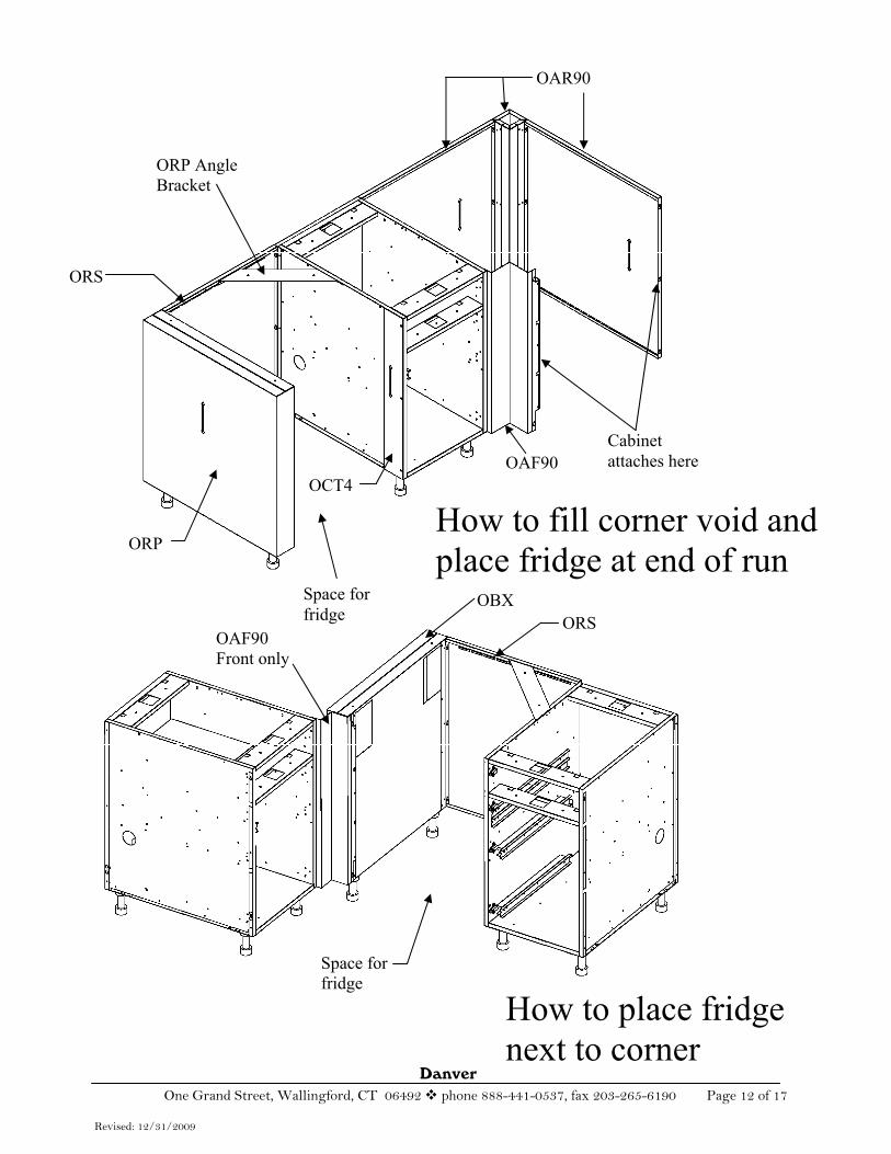
3. If a raised counter is desired for a bar-height seating area, install 41” high piers (OCP41 or OCP41E with electrical box cutout) to hold up the raised countertop. They are affixed by installing the “tongue” in the slot in the pier and putting it over the rear top rail (stretcher) of the cabinet under the counter top. Then install and tighten 3 #10 screws against, not into (no holes), the rear top rail. Install the counter top over the tongue. Install the tubular spans in the slots in the piers to help support the bar top.
4. Install locally supplied countertop.
5. Install appliances per each appliance manufacturer’s installation instructions.
6. Align doors and drawers. Enjoy!
Danver One Grand Street, Wallingford, CT 06492 phone 888-441-0537, fax 203-265-6190 Page 14 of 17
Revised: 10/19/2010
OCP Instructions
Tighten 3#10 Screws
AdjustableFeet
OptionalElectricCutout
Bracket adjustsin and out fordifferent thickness
Top Brkt fitsover column toallow for a largegluing surface
Danver One Grand Street, Wallingford, CT 06492 phone 888-441-0537, fax 203-265-6190 Page 15 of 17
Revised: 10/19/2010
Step 1
Step 2
These same steps apply to the Rear Panels. Panelinstallation should take no longer than 30 seconds
Side Panel (OSP) & Back Panel (OBP) Installation
From inside of cabinet locate 2 holes thatalign with panel bend and install 2 #10 screws.This will hold the panel in place. The panel will be under the top lip of the cabinet!This is important if you ever have to replacethe panel in the future.
Place Side Panel on top of cabinet lip. Thescrew heads on bottom of panel are foralignment only and will fall into the 2 large holesin cabinet lip. This will hold the bottom in place.
Danver One Grand Street, Wallingford, CT 06492 phone 888-441-0537, fax 203-265-6190 Page 16 of 17
Revised: 12/31/2009
CARE AND CLEANING 1. Carefully remove protective plastic peel coat from each stainless steel surface and drawer
sides. Clean stainless with stainless steel cleaner in direction of grain. Rubbing across the grain direction may produce minor scratches. Some good cleaners are Weiman, Stainless Steel Magic and Sheila Shine.
2. In a salt air environment, a slightly more oily cleaner like Sheila Shine will protect better against oxidation, pitting or slight surface rust. Cleaning the surfaces periodically will protect the finish for many years. In a heavy salt area, you will have to clean more frequently as salt breaks down into highly corrosive chlorine that will attack the metal. Surface corrosion will not affect performance of the product, but will affect the look.
3. The cabinet’s “working surfaces” are constructed from stainless steel with no grain. It is somewhat more scratch resistant but equal in durability to the grained surfaces. Use the same stainless cleaner as on the rest of the surfaces.
LOW MAINTENANCE FINISHES To address the public’s resistance to doing maintenance, Danver has developed several low to no maintenance finishes. Powder coat in different styles completely seals the stainless from the environment (salt, chlorine and muriatic acid) eliminating the worry of pitting and surface rust. The painted finishes can be cleaned with water or other household cleaner only if needed. Available on all exterior surfaces (doors, drawer fronts, panels or trim) or the complete cabinet.
1. Protect-A-Coat—Clear coat retains the look of stainless with a slightly “wet” look.
2. Painted Finishes—Powder coat colors are used to achieve a designer look or to blend in with the environment.
3. Wood Finishes—We use a powder coat painting process that transfers wood grain permanently into an exterior grade powder coat base coat to create tremendously realistic wood finishes on stainless doors and drawers. Use the wood finish on accent doors and panels, or make the kitchen all with the wood look.
Danver One Grand Street, Wallingford, CT 06492 phone 888-441-0537, fax 203-265-6190 Page 17 of 17
Revised: 12/31/2009
Danver Outdoor Cabinetry Limited Lifetime Warranty
Danver hereby warrants to the original consumer purchaser that its outdoor cabinets and related products and accessories are free from manufacturing defects and workmanship for the useful lifetime of the product. This warranty is not transferable and is for residential applications only. This warranty does not apply in the case of normal wear and tear, accidental misuse, abuse, or negligence, product modification, improper storage or improper installation. This warranty is expressly limited to repair or replacement of the defective part at the discretion of Danver, and does not include expenses incurred in the removal, shipment or installation for removal or replacement. This warranty applies only to cabinets or related products purchased through an authorized Danver dealer. This warranty is in lieu of all other implied or expressed warranties. Surface corrosion and discoloration is not covered under warranty but can be minimized or eliminated with care and cleaning.
The drawer slides were chosen for strength and durability with use. They have been treated to withstand the elements, but their warranty is limited to two (2) years. Replacements are available if necessary.
Danver reserves the right to make changes in design, construction materials and prices as conditions require and as improvements are developed, without obligation to incorporate such changes in cabinetry or related products previously manufactured by Danver.
All implied warranties, including the warranties of merchantability and of fitness for a particular purpose, are limited in duration to the period of the express warranty stated above. In no event shall Danver be liable for incidental or consequential damage.
Some states do not allow the exclusion or limitation of incidental or consequential damages, so the above limitations and exclusion may not apply to some purchasers.
This warranty gives you specific legal rights. You may have other rights, which vary from state to state.
Claims – all claims for defective cabinets or related products must be submitted to Danver in writing and must specify the defects alleged to be present. Danver will, at its discretion, either repair or replace any defective cabinets or related products.
Stainless steel surfaces can be scratched and/or dented during normal use or installation. These marks are not covered as defective material or workmanship. Keep in mind that stainless steel needs periodic maintenance; more in harsh climates. All complaints about defective surface finishes must be inspected by an authorized representative of Danver prior to installation. Danver will not be responsible for any expense involved in removing or reinstalling cabinetry with a defective finish. Danver reserves the option of either approving field repair or returning the cabinetry or component to the factory for correction. If a field repair is possible, an accurate estimate of the cost must be obtained. No action can be taken without Danver’s authorization.