Embed Size (px)
Citation preview
Journal of ELECTRICAL ENGINEERING, VOL. 55, NO. 1-2, 2004, 50–56
REVIEWS - LETTERS - REPORTS
VIRTUAL INSTRUMENTATION ANDDISTRIBUTED MEASUREMENT SYSTEMS
Viktor Smiesko — Karol Kovac∗
The development and use of programmable measurement systems have been widely explored. The possibility of modifying
the measurement procedure simply by changing the algorithm executed by the computer-based architecture without replacing
the hardware components makes the experimental activity easier. Virtual measurement systems have been introduced
to simplify the design, implementation and use of programmable measurement systems by adopting a visual interface.
Networking has also been introduced successfully in measurement to interconnect different instruments and data processing
sites into a distributed measurement system (DMS). Industries that develop and use DMS are migrating away from
proprietary hardware and software platforms in favour of open systems and standardized approaches.
K e y w o r d s: virtual instrumentation, distributed measurement system, remote and networked measurement, intercon-
nect buses.
1 INTRODUCTION
For many years electronic instruments have been easilyidentified products. Although they ranged in size andfunctionality, they all tended to be box-shaped objectswith a control panel and a display. Stand-alone electronicinstruments are very powerful, expensive and designed toperform one or more specific tasks defined by the vendor.However, the user generally cannot extend or customizethem. The knobs and buttons on the instrument, thebuilt-in circuitry, and the functions available to the user,all of these are specific to the nature of the instrument. Inaddition, special technology and costly components mustbe developed to build these instruments, making themvery expensive and hard to adapt.
Widespread adoption of the PC over the past twentyyears has given rise to a new way for scientists and engi-neers to measure and automate the world around them.One major development resulting from the ubiquity of thePC is the concept of virtual instrumentation. A virtualinstrument consists of an industry-standard computer orworkstation equipped with off-the-shelf application soft-ware, cost-effective hardware such as plug-in boards, anddriver software — which together perform the functions oftraditional instruments. Today virtual instrumentation iscoming of age, with engineers and scientists using virtualinstruments in literally hundreds of thousands of appli-cations around the globe, resulting in faster applicationdevelopment, higher quality products and lower costs.
Virtual instruments represent a fundamental shiftfrom traditional hardware-centred instrumentation sys-tems towards software-centred systems that exploit thecomputing power, productivity, display and connectivitycapabilities of popular desktop computers and worksta-tions.
Although PC and integrated circuit technologies expe-rienced significant advances in the past two decades, it is
the software that makes possible building virtual instru-ments on this foundation. Engineers and scientists are nolonger limited by traditional fixed-function instruments.Now they can build measurement and automation sys-tems that suit exactly their specific needs.
2 THE CONCEPTION OF
VIRTUAL INSTRUMENT
Usually instrumentation manufacturers provide spe-cific functions to given architecture and fixed interfacesfor measuring devices, and thus limit the application do-main of these devices. In actual use much time is requiredfor adjusting the measuring range and for saving and doc-umenting the results.
The advent of microprocessors in the measurementand instrumentation fields produced rapid modificationsof measuring device technology, soon followed by theappearance of computer-based measurement techniques.Conceptual model of early-computerized instrumentationis given in Fig. 1.
A single user controls the system, which runs exclu-sively on a piece of hardware. There is a single controlstructure, which is formed by the combination of the userand the program that controls the multiple devices at-tached to the instrumentation bus. The main challengesare the device coupling and the programming models.
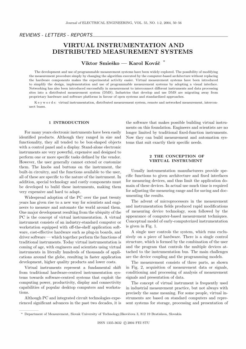
The measurement consists of three parts, as shownin Fig. 2, acquisition of measurement data or signals,conditioning and processing of analysis of measurementsignals and presentation of data.
The concept of virtual instrument is frequently usedin industrial measurement practice, but not always withprecisely the same meaning. For some people, virtual in-struments are based on standard computers and repre-sent systems for storage, processing and presentation of
∗ Department of Measurement, Slovak University of Technology,Ilkovicova 3, 812 19 Bratislava, Slovakia
ISSN 1335-3632 c© 2004 FEI STU
Journal of ELECTRICAL ENGINEERING, VOL. 55, NO. 1-2, 2004 51
USER
PROCESS
INSTRUMENTATION BUS
PROGRAM
DEVICE
DRIV ER
DEVICE 1 DEVICE 2 DEVICE n
Fig. 1. Conceptual model of early computerized instrumentation
PROCESSING
OR
ANALYSIS
ACQUISITION
AND
INSTRUMENT
CONTROL
SIGNALS
PRESENTATION
Fig. 2. The diagram of measurement process
DATA
PRESENTATION
DATA
PROCESSING
DATA
ACQUISITION
SIGNAL
GENERATION
ADDED
SOFTWARE
ADDED
HARDWAREP C
Fig. 3. The general conception of virtual instrument
measurement data. For others, a virtual instrument is acomputer equipped with software for a variety of uses in-cluding drivers for various peripherals, as well as analogueto digital and digital to analogue converters, representingan alternative to expensive conventional instruments withanalogue displays and electronics. Both views are moreor less correct. Acquisition of data by a computer can beachieved in various ways and for this reason the under-standing of the architecture of the measuring instrumentbecomes important.
A virtual instrument can be defined as an integrationof sensors by a PC equipped with specific data acquisi-tion hardware and software to permit measurement dataacquisition, processing and display.
A virtual instrument can replace the traditional frontpanel equipped with buttons and display by a virtualfront panel on a PC monitor. Virtual instruments are a
means of integration of the display, control and central-ization of complex measurement systems.
Industrial instrumentation applications, however, re-quire high rates, long distances, and multi- vendor in-strument connectivity based on open industrial networkprotocols.
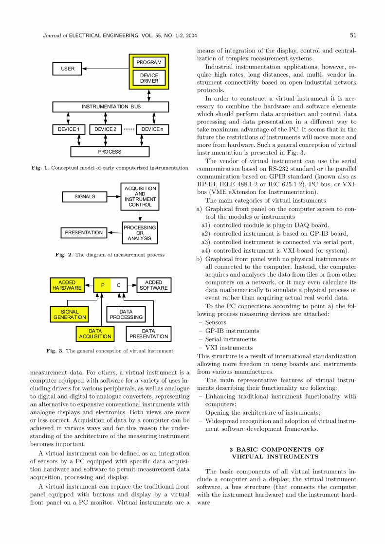
In order to construct a virtual instrument it is nec-essary to combine the hardware and software elementswhich should perform data acquisition and control, dataprocessing and data presentation in a different way totake maximum advantage of the PC. It seems that in thefuture the restrictions of instruments will move more andmore from hardware. Such a general conception of virtualinstrumentation is presented in Fig. 3.
The vendor of virtual instrument can use the serialcommunication based on RS-232 standard or the parallelcommunication based on GPIB standard (known also asHP-IB, IEEE 488.1-2 or IEC 625.1-2), PC bus, or VXI-bus (VME eXtension for Instrumentation).
The main categories of virtual instruments:
a) Graphical front panel on the computer screen to con-trol the modules or instruments
a1) controlled module is plug-in DAQ board,
a2) controlled instrument is based on GP-IB board,
a3) controlled instrument is connected via serial port,
a4) controlled instrument is VXI-board (or system).
b) Graphical front panel with no physical instruments atall connected to the computer. Instead, the computeracquires and analyses the data from files or from othercomputers on a network, or it may even calculate itsdata mathematically to simulate a physical process orevent rather than acquiring actual real world data.
To the PC connections according to point a) the fol-lowing process measuring devices are attached:
– Sensors
– GP-IB instruments
– Serial instruments
– VXI instruments
This structure is a result of international standardizationallowing more freedom in using boards and instrumentsfrom various manufactures.
The main representative features of virtual instru-ments describing their functionality are following:
– Enhancing traditional instrument functionality withcomputers;
– Opening the architecture of instruments;
– Widespread recognition and adoption of virtual instru-ment software development frameworks.
3 BASIC COMPONENTS OF
VIRTUAL INSTRUMENTS
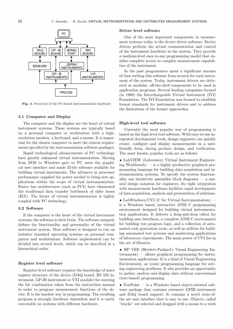
The basic components of all virtual instruments in-clude a computer and a display, the virtual instrumentsoftware, a bus structure (that connects the computerwith the instrument hardware) and the instrument hard-ware.
52 V. Smiesko — K. Kovac: VIRTUAL INSTRUMENTATION AND DISTRIBUTED MEASUREMENT SYSTEMS
DAQ
BOARD
GP - IB
BOARD
SERIAL
PORT
MXI
BOARD
SENSORS
GP - IB
INSTRUMENTS
„SERIAL“
INSTRUMENTS
VXI
INSTRUMENTS
PROCES
PC
Fig. 4. Structure of the PC-based instrumentation hardware
3.1 Computer and Display
The computer and the display are the heart of virtualinstrument systems. These systems are typically basedon a personal computer or workstation with a high-resolution monitor, a keyboard, and a mouse. It is impor-tant for the chosen computer to meet the system require-ments specified by the instrumentation software packages.
Rapid technological advancements of PC technologyhave greatly enhanced virtual instrumentation. Movingfrom DOS to Windows gave to PC users the graphi-cal user interface and made 32-bit software available forbuilding virtual instruments. The advances in processorperformance supplied the power needed to bring new ap-plications within the scope of virtual instrumentation.Faster bus architectures (such as PCI) have eliminatedthe traditional data transfer bottleneck of older buses(ISA). The future of virtual instrumentation is tightlycoupled with PC technology.
3.2 Software
If the computer is the heart of the virtual instrumentsystems, the software is their brain. The software uniquelydefines the functionality and personality of the virtualinstrument system. Most software is designed to run onindustry standard operating systems on personal com-puters and workstations. Software implemented can bedivided into several levels, which can be described in ahierarchical order.
Register level software
Register-level software requires the knowledge of innerregister structure of the device (DAQ board, RS 232 in-strument, GP-IB instrument or VXI module) for enteringthe bit combination taken from the instruction manualin order to program measurement functions of the de-vice. It is the hardest way in programming. The resultingprogram is strongly hardware dependent and it is rarelyexecutable on systems with different hardware.
Driver level software
One of the most important components in measure-ment systems today is the device driver software. Devicedrivers perform the actual communication and controlof the instrument hardware in the system. They providea medium-level easy-to-use programming model that en-ables complete access to complex measurement capabili-ties of the instrument.
In the past programmers spent a significant amountof time writing this software from scratch for each instru-ment of the system. Today, instrument drivers are deliv-ered as modular, off-the-shelf components to be used inapplication programs. Several leading companies formed(in 1988) the Interchangeable Virtual Instrument (IVI)Foundation. The IVI Foundation was formed to establishformal standards for instrument drivers and to addressthe limitations of the former approaches.
High-level tool software
Currently the most popular way of programming isbased on the high-level tool software. With easy-to-use in-tegrated development tools, design engineers can quicklycreate, configure and display measurements in a user-friendly form, during product design, and verification.The most known, popular tools are as follows:
• LabVIEW (Laboratory Virtual Instrument Engineer-ing Workbench) — is a highly productive graphical pro-gramming language for building data acquisition and in-strumentation systems. To specify the system function-ality one intuitively assembles block diagrams — a nat-ural design notation for engineers. Its tight integrationwith measurement hardware facilities rapid developmentof data acquisition, analysis and presentation of solutions.
• LabWindows/CVI (C for Virtual Instrumentation) —is a Windows based, interactive ANSI C programmingenvironment designed for building virtual instrumenta-tion applications. It delivers a drag-and-drop editor forbuilding user interfaces, a complete ANSI C environmentfor building test program logic, and a collection of auto-mated code generation tools, as well as utilities for build-ing automated test systems and monitoring applicationsof laboratory experiments. The main power of CVI lies inthe set of libraries.
• HP VEE (Hewlett-Packard’s Visual Engineering En-vironment) — allows graphical programming for instru-mentation applications. It is a kind of Visual EngineeringEnvironment, an iconic programming language for solv-ing engineering problems. It also provides an opportunityto gather, analyze and display data without conventional(text-based) programming.
• TestPoint — is a Windows based object-oriented soft-ware package that contains extensive GPIB instrumentand DAQ board support. It contains a novel state-of-the art user interface that is easy to use. Objects, called“stocks” are selected and dragged with a mouse to a work
Journal of ELECTRICAL ENGINEERING, VOL. 55, NO. 1-2, 2004 53
area (panel). Logic flow is easily established with a pointand drag action list. TestPoint takes advantage of everyMicrosoft Windows features.
• Measurement Studio — is a measurement tool for dataacquisition, analysis, visualization and Internet connec-tivity. This development tool helps you build your testsystem by integrating into your existing Microsoft com-piler. Measurement Studio provides a collection of con-trols and classes designed for building virtual instrumen-tation systems inside Visual Basic or Visual C++. WithMeasurement Studio you can configure plug-in data ac-quisition boards, GPIB instruments, and serial devicesfrom property pages without writing any code. Withuser interface components you can configure real-time 2Dand 3D graphs, knobs, meters, gauges, dials, tanks, ther-mometers, binary switches, and LEDs. With powerful In-ternet components, you can share live measurement dataamong applications via the Internet.
SCPI — Standard commands for programmable
instruments
SCPI is not a software tool as are former systems, butit is an effective aid enabling easy standardised control ofprogrammable instruments. SCPI decreases developmenttime and increases a readability of test programs. SCPIprovides an easy understandable command set, guaran-tees a well-defined instrument behaviour under all condi-tions, which prevents unexpected instrument behaviour.Although IEEE 488.2 is used as basis of SCPI, it definesprogramming commands that we can use with any typeof hardware or communication link. It has an open struc-ture. The SCPI Consortium continues in adding com-mands and functionality to the SCPI standard.
Real-time and embedded control has been long thedomain of specialised programs. Advances in industry-standard technologies including more reliable operatingsystems, more powerful processors and computer-basedreal-time engineering tools are introducing new levels ofcontrol and determinism to virtual instrumentation. Thispresents new opportunities for scientists to take on in-creasingly sophisticated real-time and embedded develop-ment. Software scales across development on the PC intodevelopment in real-time and embedded applications. Sci-entists and engineers can move into new application areaswithout a steep learning curve because the software itselfevolves to incorporate emerging computer technologies.
3.3 Interconnect Buses
Four types of interconnect buses dominate the indus-try: the serial connection (serial port), the GPIB, the PCbus and VXI bus.
Serial port. Serial communication based on RS-232standard is the simplest way of using a computer in mea-surement applications and control of instruments. Serialcommunication is readily available via the serial port ofany PC and it is limited in data transmission rate and dis-tance (up to 19.2 Kbytes/sec, recently 115 Kbytes/sec,
and 15 m) and it allows only one device to be connectedto a PC.
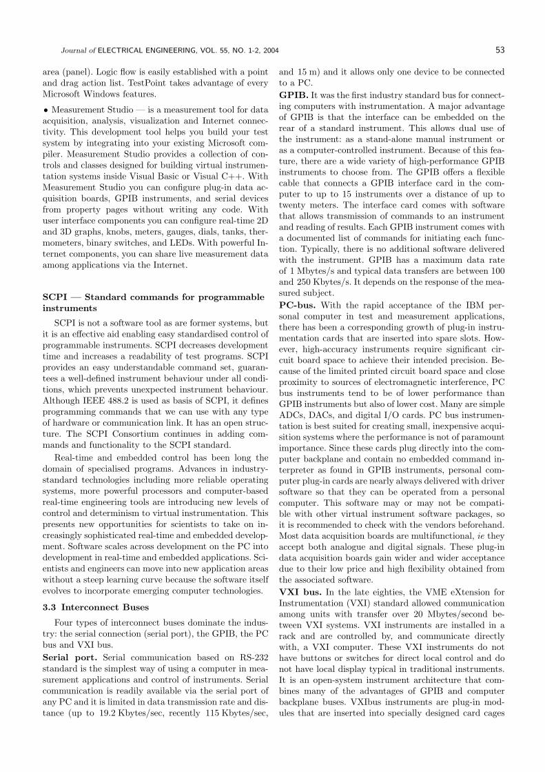
GPIB. It was the first industry standard bus for connect-ing computers with instrumentation. A major advantageof GPIB is that the interface can be embedded on therear of a standard instrument. This allows dual use ofthe instrument: as a stand-alone manual instrument oras a computer-controlled instrument. Because of this fea-ture, there are a wide variety of high-performance GPIBinstruments to choose from. The GPIB offers a flexiblecable that connects a GPIB interface card in the com-puter to up to 15 instruments over a distance of up totwenty meters. The interface card comes with softwarethat allows transmission of commands to an instrumentand reading of results. Each GPIB instrument comes witha documented list of commands for initiating each func-tion. Typically, there is no additional software deliveredwith the instrument. GPIB has a maximum data rateof 1 Mbytes/s and typical data transfers are between 100and 250 Kbytes/s. It depends on the response of the mea-sured subject.
PC-bus. With the rapid acceptance of the IBM per-sonal computer in test and measurement applications,there has been a corresponding growth of plug-in instru-mentation cards that are inserted into spare slots. How-ever, high-accuracy instruments require significant cir-cuit board space to achieve their intended precision. Be-cause of the limited printed circuit board space and closeproximity to sources of electromagnetic interference, PCbus instruments tend to be of lower performance thanGPIB instruments but also of lower cost. Many are simpleADCs, DACs, and digital I/O cards. PC bus instrumen-tation is best suited for creating small, inexpensive acqui-sition systems where the performance is not of paramountimportance. Since these cards plug directly into the com-puter backplane and contain no embedded command in-terpreter as found in GPIB instruments, personal com-puter plug-in cards are nearly always delivered with driversoftware so that they can be operated from a personalcomputer. This software may or may not be compati-ble with other virtual instrument software packages, soit is recommended to check with the vendors beforehand.Most data acquisition boards are multifunctional, ie theyaccept both analogue and digital signals. These plug-indata acquisition boards gain wider and wider acceptancedue to their low price and high flexibility obtained fromthe associated software.
VXI bus. In the late eighties, the VME eXtension forInstrumentation (VXI) standard allowed communicationamong units with transfer over 20 Mbytes/second be-tween VXI systems. VXI instruments are installed in arack and are controlled by, and communicate directlywith, a VXI computer. These VXI instruments do nothave buttons or switches for direct local control and donot have local display typical in traditional instruments.It is an open-system instrument architecture that com-bines many of the advantages of GPIB and computerbackplane buses. VXIbus instruments are plug-in mod-ules that are inserted into specially designed card cages
54 V. Smiesko — K. Kovac: VIRTUAL INSTRUMENTATION AND DISTRIBUTED MEASUREMENT SYSTEMS
To another
GPIB
instrument
VXI Mainframe
INST
#1
INST
#2
RAM INST
#3
CPU
...GPIB
VXI
GPIB
Controller
Fig. 5. A VXIbus system controlled by GPIB
UNK
MXI
VXI
INST
#1
INST
#2
INST
#3
RAM CPU
VXI Mainframe
MXI
...
Fig. 6. A VXIbus system controlled over a high-speed MXIbus
cable
PC INST
#1
VXI Mainframe
INST
#2
RAM INST
#3
INST
#4......
Fig. 7. A VXIbus system controlled by an embedded VXIbuscomputer inserted into the mainframe
known as “mainframes”. Mainframes include power sup-plies, air cooling equipment and backplane communica-tion for the modules. The VXIbus is unique in that itcombines a computer backplane based on the VME-busfor high-speed communication and offers a quality EMCenvironment that allows high-performance instrumenta-tion similar to that found in GPIB. As a result, muchmore compact measuring systems can be built.
There are three ways to communicate between thecomputer and the VXI bus instruments.
a) The first method is by using GPIB. In this case, aGPIB to VXIbus converter module is plugged into theVXIbus mainframe and a standard interface cable con-nects it and the GPIB interface card in the computer.The advantages and disadvantages of this techniqueare very similar to a pure GPIB design. This systemtends to be easy to program, but data speeds are lim-ited to GPIB speeds. However, because the internaldata speeds within the VXIbus mainframe can exceed10 Mbytes/s, often a high-speed application is solvedby local high-speed acquisition and processing occur-ring within the mainframe and high level results trans-fer to the computer over GPIB. Figure 5 shows an ex-ample of VXIbus system using GPIB.
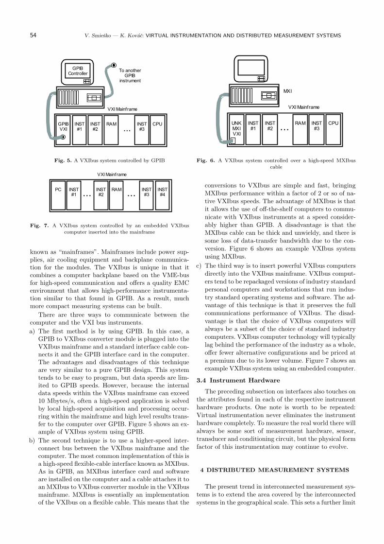
b) The second technique is to use a higher-speed inter-connect bus between the VXIbus mainframe and thecomputer. The most common implementation of this isa high-speed flexible-cable interface known as MXIbus.As in GPIB, an MXIbus interface card and softwareare installed on the computer and a cable attaches it toan MXIbus to VXIbus converter module in the VXIbusmainframe. MXIbus is essentially an implementationof the VXIbus on a flexible cable. This means that the
conversions to VXIbus are simple and fast, bringingMXIbus performance within a factor of 2 or so of na-tive VXIbus speeds. The advantage of MXIbus is thatit allows the use of off-the-shelf computers to commu-nicate with VXIbus instruments at a speed consider-ably higher than GPIB. A disadvantage is that theMXIbus cable can be thick and unwieldy, and there issome loss of data-transfer bandwidth due to the con-version. Figure 6 shows an example VXIbus systemusing MXIbus.
c) The third way is to insert powerful VXIbus computersdirectly into the VXIbus mainframe. VXIbus comput-ers tend to be repackaged versions of industry standardpersonal computers and workstations that run indus-try standard operating systems and software. The ad-vantage of this technique is that it preserves the fullcommunications performance of VXIbus. The disad-vantage is that the choice of VXIbus computers willalways be a subset of the choice of standard industrycomputers. VXIbus computer technology will typicallylag behind the performance of the industry as a whole,offer fewer alternative configurations and be priced ata premium due to its lower volume. Figure 7 shows anexample VXIbus system using an embedded computer.
3.4 Instrument Hardware
The preceding subsection on interfaces also touches onthe attributes found in each of the respective instrumenthardware products. One note is worth to be repeated:Virtual instrumentation never eliminates the instrumenthardware completely. To measure the real world there willalways be some sort of measurement hardware, sensor,transducer and conditioning circuit, but the physical formfactor of this instrumentation may continue to evolve.
4 DISTRIBUTED MEASUREMENT SYSTEMS
The present trend in interconnected measurement sys-tems is to extend the area covered by the interconnectedsystems in the geographical scale. This sets a further limit
Journal of ELECTRICAL ENGINEERING, VOL. 55, NO. 1-2, 2004 55
CONTROLLER
GPIB
CONTROLLER
DAQ
CONTROLLER
RS 232
CONTROLLER
VXI
INSTRUMENT
1
INSTRUMENT
2
INSTRUMENT
3
TERMINAL
1
TERMINAL
2
TERMINAL
3
FILE
SERVER
MXI
VXI
LAN
GPIB
MXI
RS232 INS
TR
UM
EN
T4
INS
TR
UM
EN
T5
...
Fig. 8. Block diagram of distributed measurement system based
on LAN
INTERNET
EXPLORER
DATA
SOCKET
CONTROLL
DISPLAY FILES FTP
URL
Fig. 9. The architecture of a distributed system based on Internet
to the use of such systems. As in the case of large and com-plex plants, a structured networked measurement systemcan be adopted by scaling its use to the geographical area.The geographical process to be monitored and controlledis partitioned into cells that can be dealt with by a sin-gle processing unit or a group of locally connected units.Geographically distributed units are connected by a geo-graphical computer network into a distributed measure-ment system. In this case communication delays usuallycannot be neglected. This is even more relevant if the traf-fic in the computer network is not negligible due to thenumber of computers connected and the amount of com-munications, especially if a public computer network isused to realise the interconnections among the measuringprocessing units.
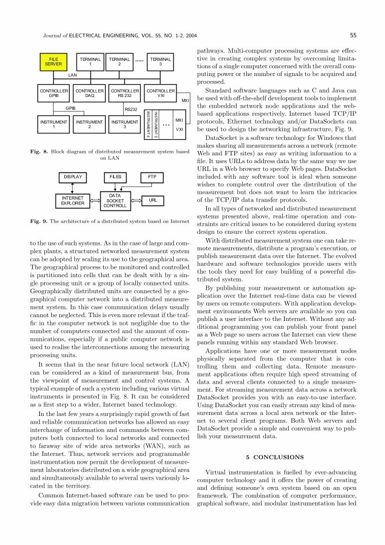
It seems that in the near future local network (LAN)can be considered as a kind of measurement bus, fromthe viewpoint of measurement and control systems. Atypical example of such a system including various virtualinstruments is presented in Fig. 8. It can be consideredas a first step to a wider, Internet based technology.
In the last few years a surprisingly rapid growth of fastand reliable communication networks has allowed an easyinterchange of information and commands between com-puters both connected to local networks and connectedto faraway site of wide area networks (WAN), such asthe Internet. Thus, network services and programmableinstrumentation now permit the development of measure-ment laboratories distributed on a wide geographical areaand simultaneously available to several users variously lo-cated in the territory.
Common Internet-based software can be used to pro-vide easy data migration between various communication
pathways. Multi-computer processing systems are effec-tive in creating complex systems by overcoming limita-tions of a single computer concerned with the overall com-puting power or the number of signals to be acquired andprocessed.
Standard software languages such as C and Java canbe used with off-the-shelf development tools to implementthe embedded network node applications and the web-based applications respectively. Internet based TCP/IPprotocols, Ethernet technology and/or DataSockets canbe used to design the networking infrastructure, Fig. 9.
DataSocket is a software technology for Windows thatmakes sharing all measurements across a network (remoteWeb and FTP sites) as easy as writing information to afile. It uses URLs to address data by the same way we useURL in a Web browser to specify Web pages. DataSocketincluded with any software tool is ideal when someonewishes to complete control over the distribution of themeasurement but does not want to learn the intricaciesof the TCP/IP data transfer protocols.
In all types of networked and distributed measurementsystems presented above, real-time operation and con-straints are critical issues to be considered during systemdesign to ensure the correct system operation.
With distributed measurement system one can take re-mote measurements, distribute a program’s execution, orpublish measurement data over the Internet. The evolvedhardware and software technologies provide users withthe tools they need for easy building of a powerful dis-tributed system.
By publishing your measurement or automation ap-plication over the Internet real-time data can be viewedby users on remote computers. With application develop-ment environments Web servers are available so you canpublish a user interface to the Internet. Without any ad-ditional programming you can publish your front panelas a Web page so users across the Internet can view thesepanels running within any standard Web browser.
Applications have one or more measurement nodesphysically separated from the computer that is con-trolling them and collecting data. Remote measure-ment applications often require high speed streaming ofdata and several clients connected to a single measure-ment. For streaming measurement data across a networkDataSocket provides you with an easy-to-use interface.Using DataSocket you can easily stream any kind of mea-surement data across a local area network or the Inter-net to several client programs. Both Web servers andDataSocket provide a simple and convenient way to pub-lish your measurement data.
5 CONCLUSIONS
Virtual instrumentation is fuelled by ever-advancingcomputer technology and it offers the power of creatingand defining someone’s own system based on an openframework. The combination of computer performance,graphical software, and modular instrumentation has led
56 V. Smiesko — K. Kovac: VIRTUAL INSTRUMENTATION AND DISTRIBUTED MEASUREMENT SYSTEMS
to the emergence of virtual instruments, which are sub-stantially different from their physical ancestors. Virtualinstruments are manifested in different forms rangingfrom graphical instrument panels to complete instrumentsystems. Modular instrumentation building blocks are be-coming more prevalent in the industry and are allow-ing users to develop capabilities unattainable using tra-ditional instrument architectures. Despite these changeshowever, the measurement paradigm remains unaltered.This might be the proper platform for the new develop-ment.
The trend in virtual instrumentation increasingly inte-grates the measurement systems into more complex moni-toring and control systems distributed over different (pos-sibly geographically distant) locations. The remote in-strumentation control is becoming popular since the net-works have become reliable and world wide and almostevery new instrument embeds programmable capabilities.
The past has shown that unless proper standards areavailable, diversification due to ad-hoc solutions will slowthe progress in the field. Thus, it seems a proper chal-lenge for the future to start thinking of standardizationof virtual instrumentation and distributed measurementsystems.
References
[1] CRISTALDI, L.—FERRERO, A.—PIURI, V. : Programmable
Instruments, Virtual Instruments and Distributed Measure-
ment Systems. IEEE Instrumentation & Measurement Maga-
zine, Sep., 1999, 20–27.
[2] BAICAN, R.—NESCULESCU, D. : Applied Virtual Instrumen-
tation, WIT Press, Boston, 2000.
[3] GOLDBERG, H. : What is Virtual Instrumentation? IEEE
Instrumentation & Measurement Magazine, December 2000,
10–13.
[4] SPOEDLER, H. J. W. : Virtual Instruments and Virtual En-
vironments. IEEE Instrumentation & Measurement Magazine,
Vol. 2, 1999, 14–19.
[5] SMIESKO, V.—KUKUCA, P. : Measurement on the Threshold
of the Third Millennium, J. Electrical Engineering 52 No. 7-8
(2001), 240–243.
[6] TRUCHARD, J. : Future of Virtual Instrumentation, NI Week,
2002.
[7] DES-JARDIN, L. : Virtual Instruments and the Role of Soft-
ware. Electronic Instrument Handboock. McGraw-Hill, 1995,
44.1–44.14.
[8] GALWAS, B. A.—RAK, R. J. : Virtual Laboratory — a Fu-
ture Part of the New Web-Based Model of Undergraduate Engi-
neering Studies Developed by Warsaw University of Technology.
Joint IMEKO TC-1 & XXXIV MKM Conference 2002, Wroclaw,
8-12 September, 2002.
[9] McCONNELL, E. : The Future of Virtual Instrumentation. Sen-
sors, July 1997, 237–240.
[10] EPPLER, B. : A Beginners Guide to SCPI, Addison-Wesley
Publishing Company Inc., 1999.
[11] BERTOCCO, M.—FERRARIS, F.—OFFELLI, C.—PARVIS,
M. : A Client-Server Architecture for Distributed Measurement
Systems, IEEE Transactions on Instrumentation and Measure-
ment 47 No. 5 (1998), 1143–1148.
[12] LEE, K. B.—SCHNEEMAN, R. D. : Internet-Based Distributed
Measurement System and Control Application, IEEE Instru-
mentation & Measurement Magazine, June 1999, 23–27.
[13] TAN, K. K.—SOH, C. Y. : Instrumentation on the Internet,
Engineering Science and Education Journal IEE 10 No. 2 (2001),
61–67.
[14] FERRERO, A.—PIURI, V. : A Simulation Tool for Virtual
Laboratory Experiments in a WWW Environment, Proc. IEEEConf. on Instrumentation and Measurement Technology, St.
Paul, Minnesota, USA, 18–21 May 1998, 1, 102–107.
[15] SCPI: Standard Commands for Programmable Instruments, ver-
sion 1991.0, May 1991.
[16] ni.com/dvi.
[17] SMIESKO, V.—KOVAC, K.—KAZICKA, R. : VXI-bus as a
Tool for Dynamic Testing, Proc. Int. Conf. CATE 93, Brno,
1993, 283–287.
[18] ANSI/IEEE Std. 488.1 — 1987, IEEE Standard Digital Interface
for Programmable Instrumentation.
[19] ANSI/IEEE Std. 488.2 — 1987, IEEE Standard Codes, Formats,
Protocols and Common Commands.
[20] SMIESKO, V. : Some Properties of VXI System in Relation to
HP-IB, Proceedings Precise Measurement in Army. Brno, 1991,
68–71.
[21] VXI-bus System Specification, Revision 1.3, Tektronix.
[22] ONDRASOVA, I.—SMIESKO, V.—SETNICKA, V. : Contri-
bution to the Efficiency of GPIB Instrumentation. In: Measure-
ment Science Review. Vol. 1, No. 1, 2001, 59–62.
[23] HELSEL, R. : Visual Programming for PH VEE, Prentice HallPTR, 1997.
[24] HP VEE for Windows User Manual, Hewlett-Packard Corp.,1993.
[25] LabWindows/CVI User Manual, National Instr. Corp., Austin1994.
[26] Test Point Demo System, Keithley Instruments, 1992.
[27] EREN, H.—NICHOLS, W. J.—WONGSO, I. : Towards anInternet-Based Virtual-Wire Environment with Virtual Instru-
mentation. IEEE Instrumentation and Measurement, Confer-ence, Budapest, Hungary, May 21–23, 2001, 817–820.
[28] JASENEK, J. : Sensors with Distributed Parameters on theBasis of POTDR, Journal of Electr. Eng 53 No. 9/s (2002),101-106, Presented at XVI-th International Conference EMFM,
Bratislava, Sept. 11-13, 2002.
[29] KAZICKA, R., ONDRASOVA, I.—SMIESKO, V. : Improving
the AT&MS Parameters, J. Electrical Engineering 46 No. 7(1995), 261–264.
[30] ONDRASOVA, I.—SETNICKA, V.—SMIESKO, V. : Auto-
mated Instrumentation Application. In: 12th International Sci-
entific Conference “Radioelektronika 2002”, Bratislava, Slovak
Republic, 14–16 May 2002, 182–185.
Received 17 October 2003
Viktor Smiesko (Prof, Ing, CSc) was born in Zlatovce,Czechoslovakia, in 1948. He graduated with honors in 1970and received the CSc (PhD) degree at the Faculty of Elec-trical Engineering, Slovak Technical University. Currently isFull Professor for Instrumentation at the Faculty of ElectricalEngineering and Information Technology, Slovak Universityof Technology. His research interests are in the areas of auto-mated instrumentation and electromagnetic compatibility.
Karol Kovac (Doc, Ing, CSc) was born in Bratislava, Slo-vakia on June 9, 1952. He received the Ing (MSc) degree withhonors in 1976 and the CSc (PhD) degree in electrical engi-neering from the Faculty of Electrical Engineering of the Slo-vak Technical University, Bratislava. Since 1976 he has beenwith the Department of Measurement of the Faculty of Elec-trical Engineering and Information Technology, Slovak Uni-versity of Technology, now as Associate professor for ElectricMeasurement. His research interests are in the area of com-puter modelling and measurement of ESD pulse processes.


![COMPARISONOFHONEYBEEMATINGOPTIMIZATION …iris.elf.stuba.sk/JEEEC/data/pdf/3_113-01.pdf · 2013. 5. 22. · system stability enhancement through improved damping of power swings [12]](https://img.pdfslide.net/doc/110x75/603e07791beee513e52b6291/comparisonofhoneybeematingoptimization-iriselfstubaskjeeecdatapdf3113-01pdf.jpg)