Embed Size (px)
Citation preview
Virtual Router Redundancy
Protocol (VRRP)
Technical Support Guide
2
VRRP Technical Support Guide
www.netcommwireless.com
v1.0
Copyright
Copyright© 2015 NetComm Wireless Limited. All rights reserved.
The information contained herein is proprietary to NetComm Wireless. No part of this document may be translated, transcribed,
reproduced, in any form, or by any means without prior written consent of NetComm Wireless.
Please note: This document is subject to change without notice.
DOCUMENT VERSION DATE
1.0 - Initial document release 28 July 2015
Table 1 - Document Revision History
Note: Before performing the instructions in this guide, please ensure that you have the latest firmware version installed on
your router. Visit http://www.netcommwireless.com to download the latest firmware.
www.netcommwireless.com
VRRP Technical Support Guide
3 v1.0
Table of contents Applicable devices ........................................................................................................................................................................ 4
Introduction .................................................................................................................................................................................... 4
What is VRRP? .............................................................................................................................................................................................. 4
VRRP Terminology ......................................................................................................................................................................................... 5
Router VRRP Configuration Page ................................................................................................................................................................... 6
VRRP in Action – How it operates on Ethernet ................................................................................................................................................ 7
VRRP in Action – Test VRRP for 3G Mobile Broadband Failover Internet Connection on Ethernet ................................................................... 12
4
VRRP Technical Support Guide
www.netcommwireless.com
v1.0
Applicable devices This document is applicable to the following NetComm Wireless devices:
NTC-6908
NTC-6908-02
NTC-6520
NTC-6200
NTC-30WV
NTC-30WV-02
NTC-40WV
NTC-140W
NWL-11
NWL-15
Introduction
What is VRRP? VRRP (Virtual Router Redundancy Protocol) is a non-proprietary redundancy protocol designed to increase the availability of the
default gateway servicing hosts on the same subnet. The Virtual Router Redundancy Protocol is a standards-based alternative to
Cisco's proprietary Hot Standby Router Protocol (HSRP) concept defined in IETF standard RFC 3768. The two technologies are
similar in concept, but are not compatible. The advantage of using VRRP is that you gain a higher availability for the default path
without requiring configuration of dynamic routing or router discovery protocols on every end host.
VRRP routers, viewed as a "redundancy group", share the responsibility for forwarding packets as if they "owned" the IP address
corresponding to the default gateway configured on the hosts. At any time, one of the VRRP routers acts as the master, and other
VRRP routers act as backups. If the master router fails, a backup router becomes the new master. In this way, router redundancy is
always provided, allowing traffic on the LAN to be routed without relying on a single router.
The physical router that is currently forwarding data on behalf of the virtual router is called the master router. There is always a
master for the shared IP address. If the master goes down, the remaining VRRP routers elect a new master VRRP router. The new
master forwards packets on behalf of the owner by taking over the virtual MAC address used by the owner.
Master routers have a priority of 255 and backup router(s) can have priority between 1 and 254. A virtual router must use 00-00-5E-
00-01-XX as its (MAC) address. The last byte of the address (XX) is the Virtual Router Identifier (VRID), which is different for each
virtual router in the network. This address is used by only one physical router at a time, and is the only way that other physical
routers can identify the master router within a virtual router.
www.netcommwireless.com
VRRP Technical Support Guide
5 v1.0
VRRP Terminology Virtual Router A single router image created through the operation of one or more routers running VRRP.
VRRP Instance A program, implementing VRRP, running on a router. A single VRRP instance can provide VRRP capability for more than one virtual
router.
Virtual Router ID Also called VRID, this is a numerical identification of a particular virtual router. VRIDs must be unique on a given network segment.
Virtual Router IP An IP address associated with a VRID that other hosts can use to obtain network service from. The VRIP is managed by the VRRP
instances belonging to a VRID.
Virtual MAC address For media that use MAC addressing (such as Ethernet), VRRP instances use predefined MAC addresses for all VRRP actions
instead of the real adapter MAC addresses. This isolates the operation of the virtual router from the real router providing the routing
function. The VMAC is derived from the VRID.
Master The one VRRP instance that performs the routing function for the virtual router at a given time. Only one master is active at a time
for a given VRID. Also refers to the state of the VRRP FSM when the VRRP instance is operating as master (that is, “master state”).
Backup VRRP instances for a VRID that are active but not in the master state. Any number of backups can exist for a VRID. Backups are
ready to take on the role of master if the current master fails. Also refers to the state of the VRRP FSM when the VRRP instance is
operating as backup (that is, “backup state”).
Priority Different VRRP instances are assigned a priority value, as a way of determining which router will take on the role of master if the
current master fails. Priority is a number from 1 to 254 (0 and 255 are reserved). Larger numbers have higher priority.
Owner If the virtual IP address is the same as any of the IP addresses configured on an interface of a router, that router is the owner of the
virtual IP address. The priority of the VRRP instance when it is the VIP owner is 255, the highest (and reserved) value.
6
VRRP Technical Support Guide
www.netcommwireless.com
v1.0
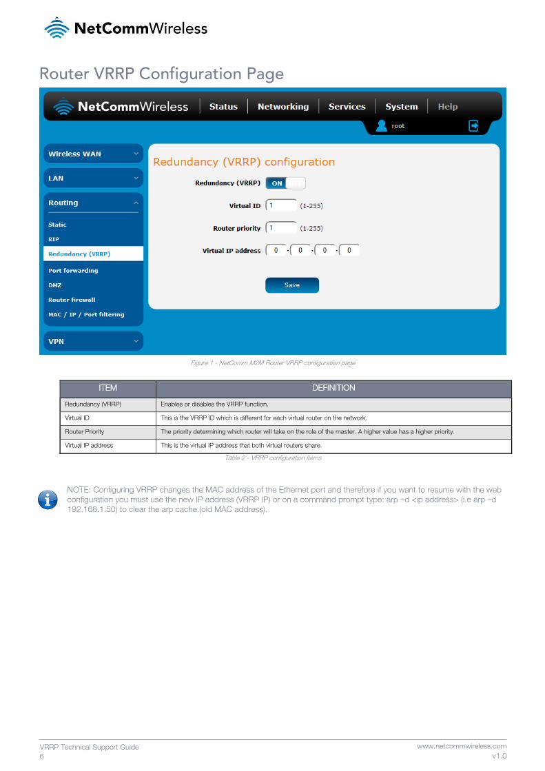
Router VRRP Configuration Page
Figure 1 - NetComm M2M Router VRRP configuration page
ITEM DEFINITION
Redundancy (VRRP) Enables or disables the VRRP function.
Virtual ID This is the VRRP ID which is different for each virtual router on the network.
Router Priority The priority determining which router will take on the role of the master. A higher value has a higher priority.
Virtual IP address This is the virtual IP address that both virtual routers share.
Table 2 - VRRP configuration items
NOTE: Configuring VRRP changes the MAC address of the Ethernet port and therefore if you want to resume with the web
configuration you must use the new IP address (VRRP IP) or on a command prompt type: arp –d <ip address> (i.e arp –d
192.168.1.50) to clear the arp cache.(old MAC address).
www.netcommwireless.com
VRRP Technical Support Guide
7 v1.0
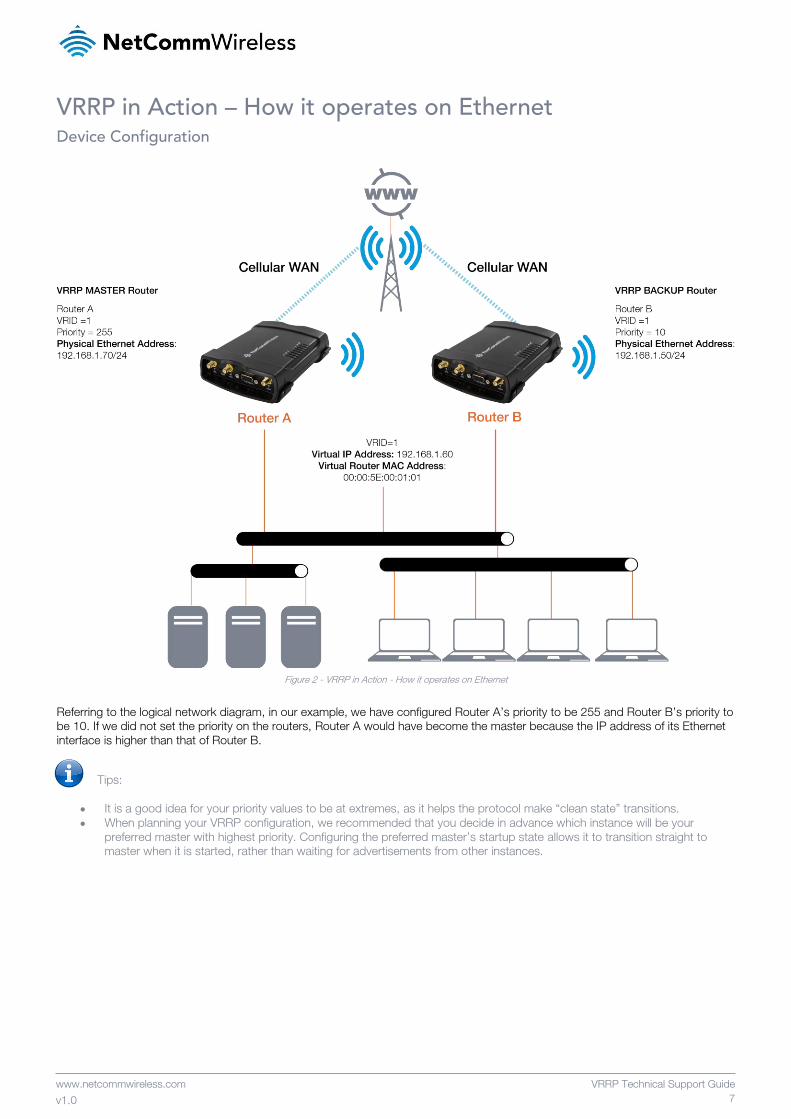
VRRP in Action – How it operates on Ethernet Device Configuration
Figure 2 - VRRP in Action - How it operates on Ethernet
Referring to the logical network diagram, in our example, we have configured Router A’s priority to be 255 and Router B’s priority to
be 10. If we did not set the priority on the routers, Router A would have become the master because the IP address of its Ethernet
interface is higher than that of Router B.
Tips:
It is a good idea for your priority values to be at extremes, as it helps the protocol make “clean state” transitions.
When planning your VRRP configuration, we recommended that you decide in advance which instance will be your
preferred master with highest priority. Configuring the preferred master’s startup state allows it to transition straight to
master when it is started, rather than waiting for advertisements from other instances.
8
VRRP Technical Support Guide
www.netcommwireless.com
v1.0
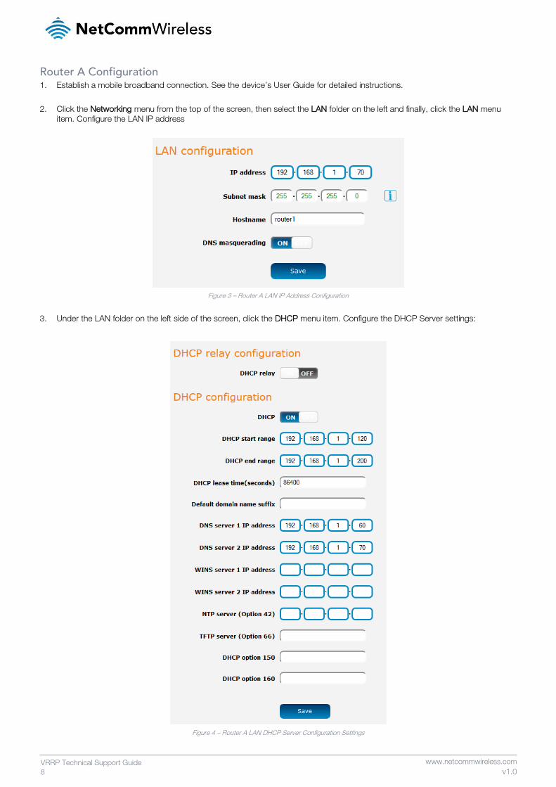
Router A Configuration 1. Establish a mobile broadband connection. See the device’s User Guide for detailed instructions.
2. Click the Networking menu from the top of the screen, then select the LAN folder on the left and finally, click the LAN menu
item. Configure the LAN IP address
Figure 3 – Router A LAN IP Address Configuration
3. Under the LAN folder on the left side of the screen, click the DHCP menu item. Configure the DHCP Server settings:
Figure 4 – Router A LAN DHCP Server Configuration Settings
www.netcommwireless.com
VRRP Technical Support Guide
9 v1.0
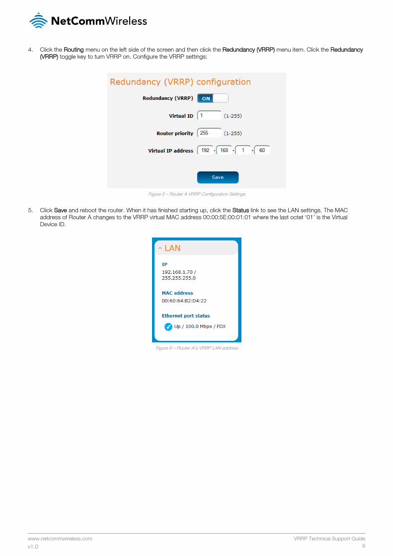
4. Click the Routing menu on the left side of the screen and then click the Redundancy (VRRP) menu item. Click the Redundancy
(VRRP) toggle key to turn VRRP on. Configure the VRRP settings:
Figure 5 – Router A VRRP Configuration Settings
5. Click Save and reboot the router. When it has finished starting up, click the Status link to see the LAN settings. The MAC
address of Router A changes to the VRRP virtual MAC address 00:00:5E:00:01:01 where the last octet ‘01’ is the Virtual
Device ID.
Figure 6 – Router A’s VRRP LAN address
10
VRRP Technical Support Guide
www.netcommwireless.com
v1.0
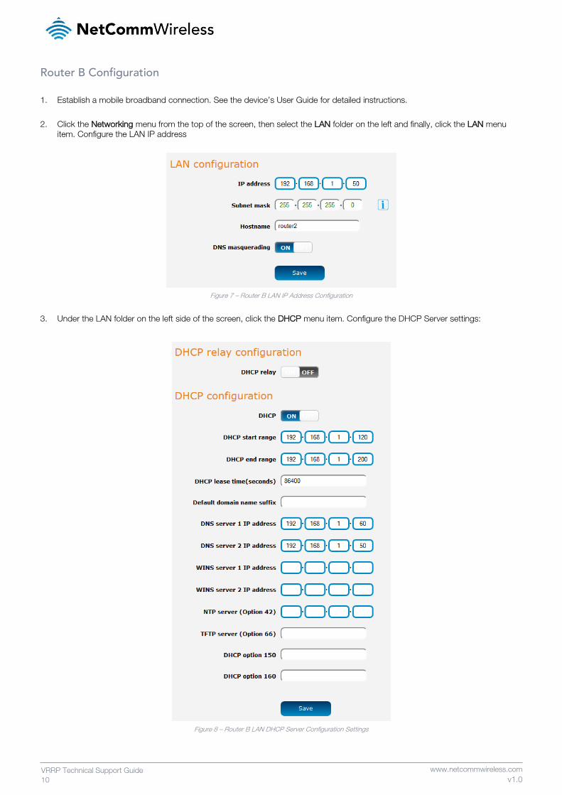
Router B Configuration
1. Establish a mobile broadband connection. See the device’s User Guide for detailed instructions.
2. Click the Networking menu from the top of the screen, then select the LAN folder on the left and finally, click the LAN menu
item. Configure the LAN IP address
Figure 7 – Router B LAN IP Address Configuration
3. Under the LAN folder on the left side of the screen, click the DHCP menu item. Configure the DHCP Server settings:
Figure 8 – Router B LAN DHCP Server Configuration Settings
www.netcommwireless.com
VRRP Technical Support Guide
11 v1.0
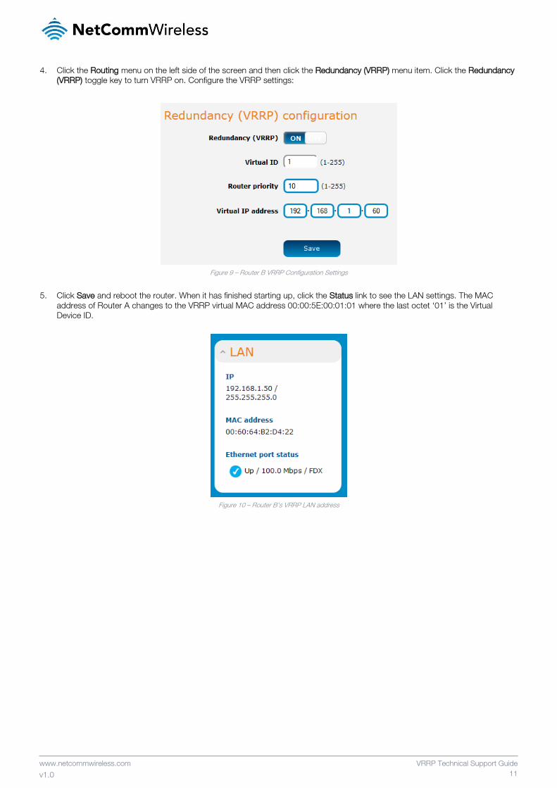
4. Click the Routing menu on the left side of the screen and then click the Redundancy (VRRP) menu item. Click the Redundancy
(VRRP) toggle key to turn VRRP on. Configure the VRRP settings:
Figure 9 – Router B VRRP Configuration Settings
5. Click Save and reboot the router. When it has finished starting up, click the Status link to see the LAN settings. The MAC
address of Router A changes to the VRRP virtual MAC address 00:00:5E:00:01:01 where the last octet ‘01’ is the Virtual
Device ID.
Figure 10 – Router B’s VRRP LAN address
12
VRRP Technical Support Guide
www.netcommwireless.com
v1.0
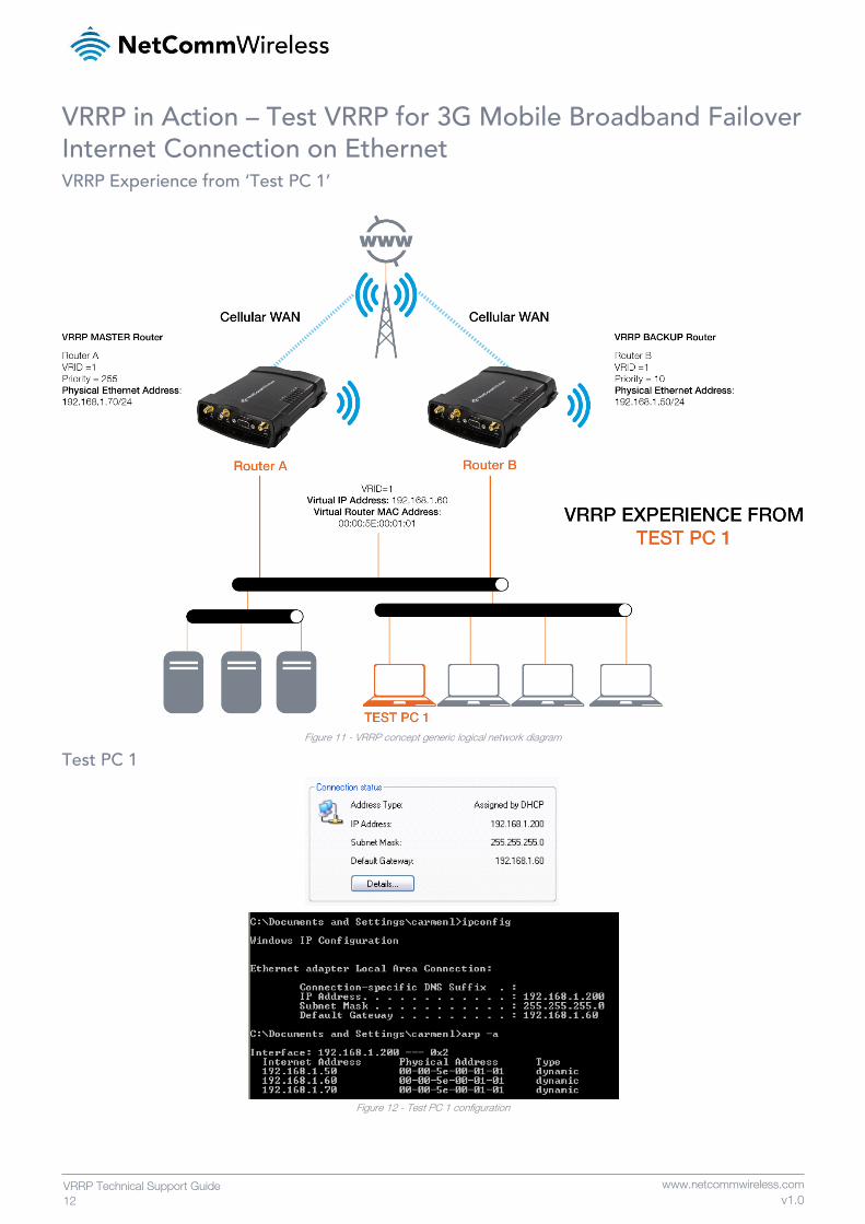
VRRP in Action – Test VRRP for 3G Mobile Broadband Failover Internet Connection on Ethernet VRRP Experience from ‘Test PC 1’
Figure 11 - VRRP concept generic logical network diagram
Test PC 1
Figure 12 - Test PC 1 configuration
www.netcommwireless.com
VRRP Technical Support Guide
13 v1.0
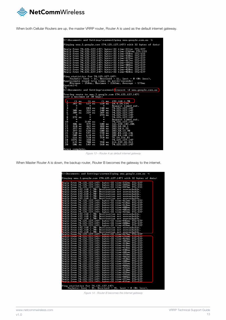
When both Cellular Routers are up, the master VRRP router, Router A is used as the default internet gateway.
Figure 13 – Router A as default internet gateway
When Master Router A is down, the backup router, Router B becomes the gateway to the internet.
Figure 14 - Router B becomes the internet gateway
14
VRRP Technical Support Guide
www.netcommwireless.com
v1.0
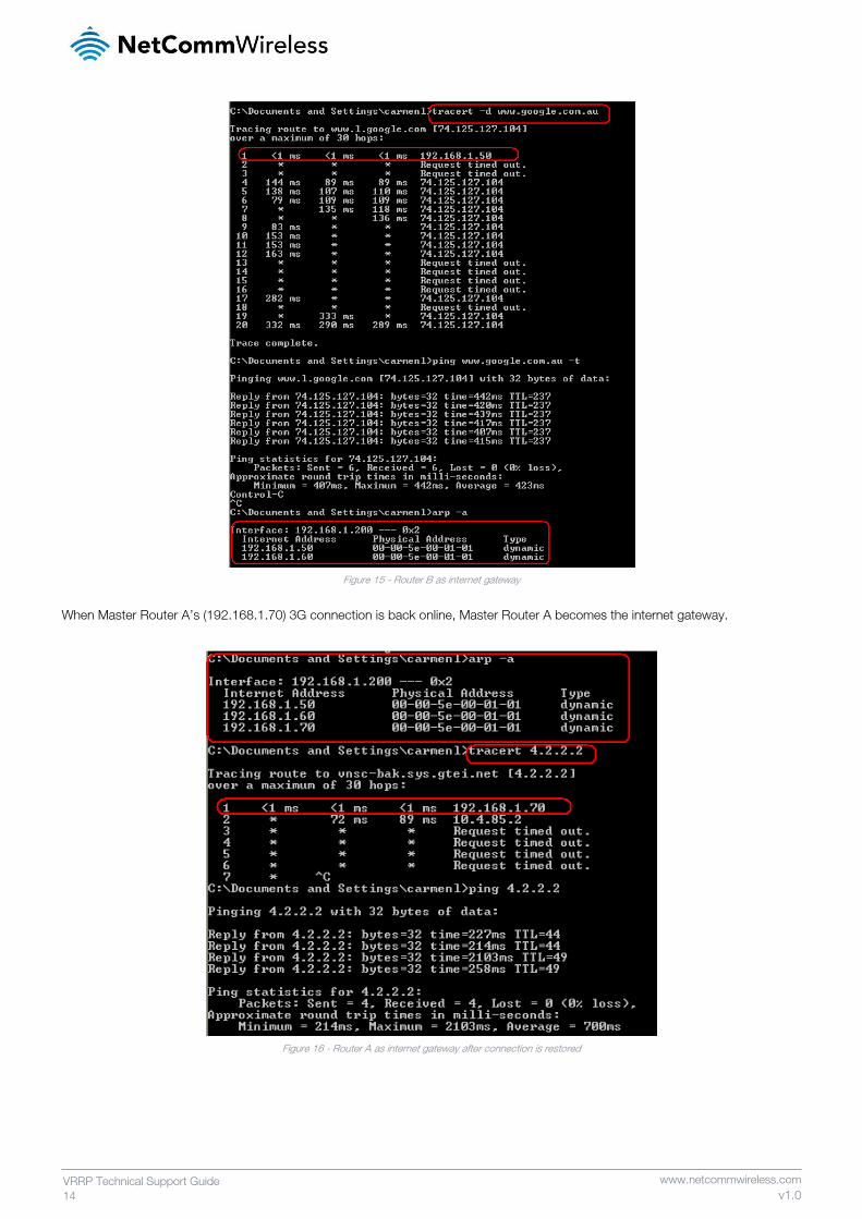
Figure 15 - Router B as internet gateway
When Master Router A’s (192.168.1.70) 3G connection is back online, Master Router A becomes the internet gateway.
Figure 16 - Router A as internet gateway after connection is restored