Embed Size (px)
Citation preview

Virtual Simulator for Design of Mobile Robot Control and Navigation Systems 515
Virtual Simulator for Design of Mobile Robot Control and Navigation Systems
Leonimer F Melo , Jose F Mangili Jr, Fernando C Dias Neto and Joao M Rosario
0
Virtual Simulator for Design of Mobile
Robot Control and Navigation Systems
Leonimer F Melo , Jose F Mangili Jr and Fernando C Dias NetoState University of Londrina
Brazil
Joao M RosarioState University of Campinas
Brazil
1. Introduction
The development of control systems for independent mobile robots has appear as a great chal-lenge for the researchers until the current days. Different platform for the project of controlsystem for independent mobile robots come being used in diverse research areas. Per manyyears the researchers have constructed control systems that present an intelligent behavior incontrolled environments, with ideal situations, but that normally does not keep the same per-formance in the real world. Innumerable systems of control exist to be used in the real world,but generally these systems are limited and they do not present an independent or intelligentbehavior.Diverse possible applications for the mobile robots already exist. In the transport, monitoring,inspection, cleanness of houses, space exploration, aid the physical deficient, among others.However, the independent mobile robots had not yet caused much impact in domestic or in-dustrial applications, mainly had the lack of a system with robust, trustworthy and flexiblecontrol that it would allow these robots operated in dynamic environments, less structural-ized, and inhabited by human beings. The development of a mobile robotic model systemwith open architecture and flexible control, with robust control system, that incorporates whatexists of modern in terms of embedded hardware technology and that makes possible the op-eration of a mobile robotic systems in a real world environment is one of the motivations ofthis work.The locomotion planning, under some types of restrictions, is a very vast field of research inthe area of the mobile robotics (Graf, 2001). The basic planning of trajectory for the mobilerobots imply the determination of a way in the space-C (configuration space) between an initialconfiguration of the robot and a final configuration, in such a way that the robot does notcollide with no obstacle in the environment, and that the planned movement is consistentwith the kinematic restrictions of the vehicle. In this context, one of the boarded points in thiswork was development of a trajectory calculator for mobile robots.One of the main motivations of this work is to propitiate a virtual environment that facili-tates the development of archetypes of embedded systems, emphasizing the implementation
26
www.intechopen.com

Mobile Robots Navigation516
of tools that allow the simulation of the kinematic, dynamic and control conditions, with realtime monitoring of all important points of the system. In this way, the proposal of a virtualsimulator of mobile robotic systems is presented together with techniques of rapid prototyp-ing.
2. The Mobile Robot Platform
Platforms for knowledge consolidation could be used in several educational and research ar-eas, such as modeling, control, automation, power systems, sensors, transmission of data,embedded electronics and software engineering. In fact, the use of the mobile robots as basefor knowledge consolidation, has been successful adopted in many educational and researchinstitutions mainly because they appear to be a quite attractive low cost solution that allowthe integration of several important areas of knowledge. Mobile robots also become a bettersolution for practical problem in modern society. These appointments shows a large appli-cability of mobile robots and a crescent request in the modern world. The proposal of thisproject is developing a generic open system for control a mobile robot and supply this need.The system emphasizes the control structure, the supervision and the transfer of information.In a context of educational and research aims the project aspects and integration solutioncompose the desired know-how acquired during the development of the system, which onecertainly would not to be approached if a commercial mobile robot was acquired.
Fig. 1. Mobile robot platform prototype.
An embedded processor, with a dedicated control software, to be used on a platform mobilerobotics, is considered. In addition to this platform another one, a commercial platform, cou-pled to a communication net, is analyzed. The set of platforms, whose objectives are makinguse of the existing communication interfaces and providing am embedded user interface al-ternative in the mobile robot, allows the creation of a powerful link with the external world.The objective of this platform is to make use of the existing communication interfaces, as well
www.intechopen.com

Virtual Simulator for Design of Mobile Robot Control and Navigation Systems 517
as to provide an embedded user interface alternative in the mobile robot. Another aspect con-sidered, is the flexibility of the hardware project, which allows the expansion of mobile robotfacilities. New sensor combinations should be used. Different supervision and control modelsshould equally be used to carry out the mobile robot tasks.This work aim to presents the implementation of a virtual environment for project simulationand conception of supervision and control systems for mobile robots and focus on the studyof the mobile robot platform, with differential driving wheels mounted on the same axis anda free castor front wheel, whose prototype used to validate the proposal system is depicted inFig. 1 and Fig. 2 which illustrate the elements of the platform.
DSP MICROCONTROLLER
BATTERY
REAR�SENSOR
WHEEL DC�MOTOR
POWER�SUPPLY
FRONT SENSORS
FPGA or�CPLD
AUXILIARY MEMORY BOARD
RF�BOARD
I/O�BOARD
Fig. 2. Mobile robot platform and elements.
3. Mobile robot modeling
It’s necessary to make the mobile robot mathematics modeling in order to extract the equa-tion and algorithms that will be used in the simulator’s blocks. This section due with that,observing the fact our physics model is a mobile robot with differential driving wheels withnonholonomic restrictions.Suppose that a robot is in a position (x, y) and “facing" along a line making an angle θ with thex axis (Fig. 3). Through manipulation of the control parameters ve and vd, the robot can movesto different positions. Determining the positions that is reachable at given control parametersis know as the forward kinematics problem for the robot (Siegwart & Nourbakhsh, 2004).Because of ve, vd and hence R and ω are functions of time, is straightforward to show (Fig.3) that, if the robot has position (x, y, θ) at some time t, and if the left and right wheels haveground-contact velocities ve and vd during the period t → t + δt, the ICC (InstantaneousCenter of Curvature) is given by
ICC = [x − R sin(θ), y + R cos(θ)]. (1)
www.intechopen.com

Mobile Robots Navigation518
Fig. 3. Forward kinematics geometry.
For better comprehension of the equation, it’s possible to simplifying ICC = I, cos(ωδt) = Cand sin(ωδt) = S, then, at time t → t + δt, the position of the robot is given by
x′
y′
θ′
=
C −S 0S C 00 0 1
x − Ix
y − Iy
θ
+
Ix
Iy
ωδt
. (2)
The Eq. (2) describes the motion of a robot rotating a distance R about its ICC with an angularvelocity given by ω (Dudek & Jekin, 2000). Different classes of robots will provide differentexpressions for R and ω (Shim et al., 1995).The forward kinematics problem is solved by integrating (2) from some initial condition(x0, y0, θ0), it is possible to compute where the robot will be at any time t based on the controlparameters ve(t) and vd(t). For the special case of a differential drive vehicle, it is given by
x(t) =1
2
∫ t
0[vd(t) + ve(t)] cos[θ(t)]dt,
y(t) =1
2
∫ t
0[vd(t) + ve(t)] sin[θ(t)]dt,
θ =1
L
∫ t
0[vd(t) − ve(t)]dt. (3)
A question more interesting, and at same time more difficult to answer, is: How can the controlparameters could be selected in a way the robot obtain a specific global position or follow aspecific trajectory? This is known as the task of determining the vehiclet’s inverse kinematics:inverting the kinematic relationship between control inputs and behavior. It is also related tothe problem of trajectory planning.
www.intechopen.com

Virtual Simulator for Design of Mobile Robot Control and Navigation Systems 519
3.1 Inverse kinematics for differential drive robots
The Eq. (3) describe a constraint on the robot velocity that cannot be integrated into a posi-tional constraint. This is known as a nonholonomic constraint and it is in general very difficult tosolve, although solutions are straightforward for limited classes of the control functions ve(t)and vd(t) (Zhao & BeMent, 1992). For example, if it is assumed that ve(t) = ve, vd(t) = vd andve �= vd, then (3) yields
x(t) =L
2
vd + ve
vd − vesin
[
t
L(vd − ve)
]
,
y(t) = −
L
2
vd + ve
vd − vecos
[
t
L(vd − ve)
]
+L
2
vd + ve
vd − ve,
θ(t) =t
L(vd − ve), (4)
where (x, y, θ)t=0 = (0, 0, 0). Given a goal time t and goal position (x, y). The Eq. (4) solvesfor vd and ve but does not provide a solution for independent control of θ. There are, in fact,infinity solutions for vd and ve from Eq. (4), but all correspond to the robot moving about thesame circle that passes through (0, 0) at t = 0 and (x, y) at t = t; however, the robot goesaround the circle different numbers of times and in different directions.
4. Control Architecture System
The control architecture system can be visualized at a logical level in the blocks diagram ofFig. 4.The system was divided into three control levels, organized in different degrees of controlstrategies. The levels can be described as:
• Supervisory control level: This represents a high level control. In this level it was pos-sible to carry out the supervision of one or more mobile robots, through the executionof global control strategies.
• Local control level: In this level the control was processed by the mobile robot embed-ded software implemented in a 8 bits microcontroller. The control strategies alloweddecision making to be done at a local level, with occasional corrections from the su-pervisory control level. Without communication with the supervisory control level, themobile robot just carried out actions based on obtained sensor data and on informationpreviously stored in its memory.
• Interface control level: This control level is restricted to strategies of control associ-ated with the interfaces of the sensor and actuators. The strategies in this level wereimplemented in hardware, through PLD (Programmable Logic Devices).
The hardware architecture, from the point of view of the mobile robot, was organized into sev-eral independent blocks, connected through the local bus which is composed by data, addressand control bus (Fig. 5). A master manager block operates several slave blocks. Blocks as-sociated with the interfaces of sensors and actuators, communication and auxiliary memorieswere subjected to direct control from the manager block. The advantage of using a commonbus was the facility to expand the system. Despite of the limitations of resources, it was pos-sible to add new blocks, allowing an adapted configuration of the robot for each task.
www.intechopen.com
Mobile Robots Navigation520
Supervision Control (Remote PC)
Data
Interface
Models
Gerenetion
Graphical
Interface
RF (Wi-Fi) Communication Interface
Onboard Trajectory Control
Bus Communication Interface
Local Control Local Control
Sensors
Interface
Sensors
Actuators
Interface
Actuators
Sensors
Interface
Sensors
Actuators
Interface
Actuators
...
...
Fig. 4. Different control levels of the proposed system.
4.1 Description of Blocks
• Supervisory control block: Is the highest level of control. In this block, the supervi-sion of one or more mobile robots is managed through the execution of global controlstrategies. It is implemented in an IBM PC platform and is connected with the localcontrol level, in the mobile robot, through Ethernet wireless WI-FI link. This protocoluses IEEE 802.11a standard for wireless TCP/IP LAN communication. It guaranteesup to 11 Mbps in the 2.4 GHz band and requires fewer access points for coverage oflarge areas. Offers high-speed access to data at up to 100 meters from base station. 14channels available in the 2.4 GHz band guarantee the expansibility of the system withthe implementation of control strategies of multiple robots.
• Master manager block: It is responsible for the treatment of all the information re-ceived from other blocks, for generation of the trajectory profile for the local controlblocks and for communication with the external world. In communication with themaster manager block, through a serial interface, a commercial platform was used,which implemented external communication using an Ethernet WI-FI wireless proto-col. The robot was seen as a TCP/IP LAN point in a communication net, allowingremote supervision through supervisory level. It’s implemented with Texas InstrumentTMDSDSK6416 DSP board Kit that uses the TMS320C6416 DSP, a 1 GHz device deliv-ering up to 8000 million instructions per second (MIPs) with highest performing.
• Sensor interface block: It is responsible for the sensor acquisition and for treatment ofdata in digital words, to be sent to the master manager block. The implementation of
www.intechopen.com

Virtual Simulator for Design of Mobile Robot Control and Navigation Systems 521
Fig. 5. Hardware architecture block diagram of the proposed system.
that interface through PLD allowed the integration of information from sensors (sensorfusion) locally, reducing manager block demand for processing. In same way, they al-lowed new programming of sensor hardware during robot operation, increasing sensortreatment flexibility.
• Actuator interface block: This block carried out speed control or position control of themotors responsible for the traction of the mobile robot. The reference signals were sup-plied through bus communication in the form of digital words. Derived informationfrom the sensor was also used in the controller implemented in PLD. Due to integrationcapacity of enormous hardware volume, PLD was appropriate to implement state ma-chines, reducing the need for block manager processing. Besides the advantage of theintegration of the hardware resources, PLD facilitated the implementation and debug-
www.intechopen.com

Mobile Robots Navigation522
ging. The possibility of modifying PLD programming allowed, for example, changes incontrol strategies of the actuators, adapting them to the required tasks.
• Auxiliary memory block: This stored the information of the sensor, and operated as alibrary for possible control strategies of sensors and actuators. Apart from this, it camewith an option for operation registration, allowing a register of errors. The best optionwas an interface PCMCIA, because this interface is easily accessible on the market, andbeing well adapted for applications in mobile robots, due to low power consumption,low weight, small dimensions, high storage capacity and good immunity to mechanicalvibrations.
• RF communication Block: It allows the establishment of a bi-directional radio link fordata communication. It operated in parallel with the commercial platform WI-FI link.The objective of these communication links was to allow the use of remote control. Theremote control has a high trajectory priority from other blocks, like supervisory controlblock, and can take the control of the mobile robot to execute, for example, emergencynecessary movements or stop. To implement this block was used a low power UHFdata transceiver module BiM-433-40.
5. Mobile Robot Simulator
The use of the system has beginning for the captation of main points for generation of themobile robot trajectory. The idea is to use a system of photographic video camera that catchesthe image of the environment where the mobile robot navigates. This initial system must beable to identify the obstacles of the environment and to generate a matrix with some strate-gic points that will be good for input data for the system of trajectory generation. Figure 6presents a general vision of the considered simulator system.
Fig. 6. General vision of the simulator system.
Fig. 7 illustrates an example of an environment with some obstacles where the robot mustnavigate. In this environment, the robot is located initially in the P1 point and the objective
www.intechopen.com

Virtual Simulator for Design of Mobile Robot Control and Navigation Systems 523
is to reach the P4 point. The generating system of initial cartesian points, must supply to themodule of trajectory generation, with the cartesian points P1, P2, P3 and P4, that are the mainpoints of the traced route.
Fig. 7. Example of an environment with some obstacles where the robot must navigate.
This system is particularly interesting and can be used, for example, in robotic soccer games,where the navigation strategies are made from images of the environment (soccer field) andthe obstacles are the other robots players. As it’s described follow, with this system, the besttrajectory can be defined and traced, respecting always the kinematics holonimics or nonholo-nomics constraints of the robotic systems in question, and to make all the simulation of thesystem foreseeing imperfections and analyzing results before the final implementation of thecontrol system in the mobile robot (Melo & Rosario, 2006).
5.1 Mobile Robot Control Structure
The tasks carried through for the mobile robots are based on the independent movement ofeach degree of freedom, coordinated from a trajectories plan based in its kinematic model. Inthe most of the cases, the tasks programming is planned with anticipation and a map of theenvironment is loaded in the robot memory board. The mobile robot accomplish the trajectorywith sequence of independent movements of each axle, until reaching the desired final posi-tion. From the knowledge of these articulated positions, easily is implemented a generator ofreferences (profile of speeds) based in the kinematic characteristics of each joint.For accomplishment of tasks in level of cartesian coordinates system and for generation of thereference signals for the position controller of each robotics joint of the mechatronics systemin study, the establishment of mathematical model based in the kinematics of the system be-comes necessary, what is described in section 3. Therefore, the control of a robot needs proce-dures to transform the data of positioning reference, such as the linear speed and the bending
www.intechopen.com

Mobile Robots Navigation524
radius, in cartesian coordinates, when it is desired to realize the control through a cartesianreferential. The Fig. 8 illustrates the mobile robot structure of control with the representativeblocks of the trajectory generation, dynamic and kinematic model of the system.
� t
Vref
TJref
AXLE 1
AXLE 2
DYNAMIC MODEL
AND CONTROLLER
VEref
VDref
VEdin
VDdin
LINEAR VELOCITY
ANGULAR SHIFT
ANGULAR
VELOCITY
BENDING RADIUS
DYNAMIC
TRAJECTORY
KINEMATIC MODEL
TJdin
Vdin
�
Rc
�
1/ZTJdin
X(t-1)
Y(t-1)
DELAY
AX
LE
SV
EL
OC
ITY
MOVEMENT
GENERATION
TR
AJE
CT
OR
YT
RA
CK
ER�t
�
�
Fig. 8. The mobile robotic control structure.
The trajectory generator receives the references data, such as the positioning vector Xre f =[xre f , yre f , θre f ], the robot reference linear speed Vre f and the robot instantaneous trajectory
radius Rcurv, that are converted into VEre f (linear speed of the left wheel) and VDre f (linearspeed of the right wheel). These differentiated speeds are received by the controller, and inthe dynamic model of the system, they are sent to the respective wheels of the robot, throughits actuators. Then are generated by the controller the vectors VEdin (dynamic linear speedof the left wheel) and VDdin (dynamic linear speed of the right wheel). Into the block ofthe kinematic model, these data are converted into the vector final positioning of the robotX = [x, y, θ].
5.2 Trajectory Generation Block
The Trajectory Generation Block of trajectory, receives some important points from the cam-era system so that the trajectory can be traced to be realized by the mobile robot. These pointsform a cartesian matrix containing more or less points, depending on the complexity of theenvironment. For a reason or purpose tests and for validation of the system, the numberof points to be fed the system was fixed in four. Nevertheless, the number of points can beincreased depending on the complexity of the environment where the mobile robot will nav-igate. Another data important to be used by the system have relation with the holonomicsconstraints of the modeled mobile robot. The bending radius must be informed to the systemto be performed in the trajectory. A time that, for a reason or purpose tests, was fixed in fourthe number of cartesian input points, must also be supplied the radius of the two curves to be
0 0.5 1 1.5 2 2.5 30
0.5
1
1.5
2
2.5
3
3.5
4
0 0.5 1 1.5 2 2.5 30
0.5
1
1.5
2
2.5
3
3.5
4
www.intechopen.com

Virtual Simulator for Design of Mobile Robot Control and Navigation Systems 525
executed for the robot. The information of distinct radius makes the system more flexible, be-ing able the trajectory to be traced with different bendings depending on the angle of directiondisplacement and on the restrictions of the robot.The graphic of the Fig. 9(a) illustrates the initial points for the trajectory generator. In thisexample, it was captured from the camera system and transmitted for the simulator the vectorx = [.1 3 .3 .1] and the vector y = [.1 3 2 4], with the bending radius for first and thesecond semicircle given by the vector r = [.4 .3]. All the measures are in meters.
0 0.5 1 1.5 2 2.5 30
0.5
1
1.5
2
2.5
3
3.5
4
(a) Initial points given to trajectory generation.
0 0.5 1 1.5 2 2.5 30
0.5
1
1.5
2
2.5
3
3.5
4
(b) Assay to the delineated trajectory.
Fig. 9. Initial points given by camera system and Assay to the delineated to trajectory.
In the Fig. 9(b) it’s possible to see the tracing of the straight lines, the semicircles and anintermediate segment of straight line indicating the start and the end of the tracing of eachcircular movement to be executed by the mobile robot.The final tracing of the mobile robot trajectory can be observed in the Fig. 10, represented byred spots.
5.3 The Virtual Simulator Implementation
Now are presented the main characteristics of a simulator of mobile robotic systems. It wasimplemented from the kinematic and dynamic model of the mechanical drive systems ofthe robotic axles, for the simulation of different control techniques in the field of the mobilerobotics, allowing to deepen the concepts of navigation systems, trajectories planning andembedded control systems. This simulator, designed in modular and opened architecture,as presented in section 4, allows the direct application of some concepts into of the mobilerobotics area, being used for its validation, and as main objective of this study, the model ofan prototype of mobile robot with nonholonomic kinematic constraint and differential drivewith two degrees of freedom (movement of linear displacement and rotation).For the simulator development, the constructive aspects of the mobile robot prototype hadbeen considered, including the kinematics and dynamics modeling of drive and control sys-tems. The simulator presents the trajectories generating module that is the first block of thesystem and was implemented with the functionality to generate a trajectory for the mobilerobot from a matrix of points supplied initially. Another presented block is the controller,implemented in the PID traditional form.Fig. 11 shows the initial page of the Virtual Mobile Robot Simulator. The user can choose oneof the captured trajectory for analyzing, take a look in the graphical results of the simulation
www.intechopen.com

Mobile Robots Navigation526
0 0.5 1 1.5 2 2.5 30
0.5
1
1.5
2
2.5
3
3.5
4
Fig. 10. The final tracing of the mobile robot trajectory.
XY Graph
Graphical Results
Valuation of the Simulation
TRAJECTORY 3
Trajectory 3 Generation
TRAJECTORY 2
Trajectory 2 Generation
TRAJECTORY 1
Trajectory 1 Generation
traj1
Traj_robo
Y1
To Workspace1
X1
To Workspace
Teta_s
To File5
V_angular_s
To File4
R_curv_s
To File3
V_linear_s
To File2 Y_s
To File1
X_s
To File
0
Tempo(s)
Signal 1
Signal Builder
Scope8
Scope4
Scope3
Scope2
Scope1
Scope
MOBILE ROBOT SIMULATOR
Manual Switch
Tempo_simulação
V_linear_refer
Traj_ref_robo
X
Y
V_linear_s
R_curv_s
V_angular
Teta
MOBILE ROBOT SYSTEM
0
Display
.5
Constant
Fig. 11. The Virtual Simulator first page.
www.intechopen.com

Virtual Simulator for Design of Mobile Robot Control and Navigation Systems 527
0 0.5 1 1.5 2 2.5 30
0.5
1
1.5
2
2.5
3
3.5
4
or implement changes in the robot model, by clicking on the mobile robot system (green mainblock).The virtual simulator system of the mobile robot is composed of three main blocks. The firstone is called movements generation block. The second one is the block of the controller anddynamic model of the mobile robot and the third one is the block of the kinematic model. TheFig. 12 illustrates the mobile robot simulator implemented into Matlab Simulink� blocks.
6
Teta5
V_angular
4
R_curv_s
3
V_linear_s
2
Y
1X
z
1
Unit�Delay5
z
1
Unit�Delay4
z
1
Unit�Delay3
z
1
Unit�Delay2
z
1
Unit�Delay1
z
1
Unit�Delay
eixoY
To�Workspace1
eixoX
To�Workspace
Y_e
To�File9
X_e
To�File8
V_lin_rodaD_e
To�File7
V_lin_rodaE_s
To�File6
V_lin_rodaD_s
To�File5
V_angular_e
To�File4
V_lin_rodaE_e
To�File3
R_curv_e
To�File2
V_linear_e
To�File10
Teta_e
To�File1
In1 Out1
SistemaRoda�Direita
In1 Out1
SistemaRoda�Esquerda
Scope3
Scope2
Scope1
[Xant]
Goto5
[Yant]
Goto4
[Teta]
Goto2
[Y]
Goto1
[X]
Goto
[Yant]
From5
[Y]
From4
[Xant]
From3
[Teta]
From2
[X]
From1
eixo_Y
From�File1
eixo_X
From�File
Vlin
X
Y
traj1
Teta_antRef
i1
ja
Vd
Ve
i2
Wref
TetaRef
Raio_c
jb
tet
V_rodas
EmbeddedMATLAB�Function1
V_d
V_e
t
Teta_ant
X_ant
Y_ant
X
Y
V_robo
R_c
Teta
W
trajetoria
EmbeddedMATLAB�Function
3
Traj_ref_robo
2
V_linear_refer
1
Tempo_simulação
Saída�Veloc.Linear�RodaEsquerda
Saída�Veloc.Linear�RodaDireita
MOVEMENT
GENERATOR
DYNAMIC�MODEL
AND�CONTROLLER
KINEMATIC�MODEL
Fig. 12. Mobile robot simulator implemented into Simulink�.
5.4 Results Graphical Analyzer
The simulator implemented in Simulink� environment allows the visualization of the inputsand outputs of the system in study.For a better understand and analysis of the behavior of the system the implementation of aresults graphical analyzer becomes essential. In this way, after realizing the simulations in thedomain of the time, timings data archives are got corresponding to the study variables (angu-lar and cartesian position, linear and angular speed and control signals), that after convenienttreatment, becomes possible to verify important results for better analysis of the system be-havior. The Fig. 13 illustrates a menu of the graphical analyzer of the mobile robotic systemin study with an example of generated graphic.One kind of analysis that is made is in relation to the linear displacement of the robot in axisX and Y. In Fig. 14, the dynamic behavior of the robot with regard to these parameters, as wellas the presented errors is illustrated.Another important graphic generated for the system, in the cartesian trajectory sub-menu, thatis the graphic of the cartesian trajectory kinematics and dynamics of the mobile robotic system
www.intechopen.com

Mobile Robots Navigation528
(a) Robot errors ana-lyzer submenu.
0 5 10 150
0.1
0.2
0.3
0.4
0.5
Time(s)E
rror
(m/s
)
Linear Velocity Error
0 5 10 15−2
−1
0
1
2
Time (s)
Err
or (r
ad/s
)
Angular Velocity Error
0 5 10 15−0.4
−0.2
0
0.2
0.4
0.6
Time (s)
Err
or (m
/s)
Linear Vel. Error of Left axle
0 5 10 15−0.4
−0.2
0
0.2
0.4
0.6
Time (s)
Err
or (m
/s)
Linear Vel. Error of Right axle
(b) A robot speeds errors graphics.
Fig. 13. Submenu of the mobile robot graphical analyzer with an example of generatedgraphic.
0 5 10 150
0.5
1
1.5
2
Time (s)
Dis
plac
emen
t (m
)
X Axis Displacement
X refX din
0 5 10 150
1
2
3
4
5
Time (s)
Dis
plac
emen
t (m
)
Y Axis Displacement
Y refY din
0 5 10 15−0.01
0
0.01
0.02
0.03
0.04
Time (s)
Err
or (m
)
X Axis Displacement Error
0 5 10 15−0.005
0
0.005
0.01
0.015
0.02
0.025
Time (s)
Err
or (m
)
Y Axis Displacement Error
Fig. 14. Dynamic behavior graphics of the robot in the X and Y axis with their errors.
−1.5 −1 −0.5 0 0.5 1 1.5 2 2.5 3 3.5
0.5
1
1.5
2
2.5
3
3.5
4
X Axis (m)
Y A
xis
(m)
Reference and Dynamic Robot Trajectory
Traj refTraj din
www.intechopen.com

Virtual Simulator for Design of Mobile Robot Control and Navigation Systems 529
0 5 10 150
0.1
0.2
0.3
0.4
0.5
Time(s)
Err
or (m
/s)
Linear Velocity Error
0 5 10 15−2
−1
0
1
2
Time (s)
Err
or (r
ad/s
)
Angular Velocity Error
0 5 10 15−0.4
−0.2
0
0.2
0.4
0.6
Time (s)
Err
or (m
/s)
Linear Vel. Error of Left axle
0 5 10 15−0.4
−0.2
0
0.2
0.4
0.6
Time (s)
Err
or (m
/s)
Linear Vel. Error of Right axle
0 5 10 150
0.5
1
1.5
2
Time (s)
Dis
plac
emen
t (m
)
X Axis Displacement
X refX din
0 5 10 150
1
2
3
4
5
Time (s)
Dis
plac
emen
t (m
)
Y Axis Displacement
Y refY din
0 5 10 15−0.01
0
0.01
0.02
0.03
0.04
Time (s)
Err
or (m
)
X Axis Displacement Error
0 5 10 15−0.005
0
0.005
0.01
0.015
0.02
0.025
Time (s)
Err
or (m
)
Y Axis Displacement Error
−1.5 −1 −0.5 0 0.5 1 1.5 2 2.5 3 3.5
0.5
1
1.5
2
2.5
3
3.5
4
X Axis (m)
Y A
xis
(m)
Reference and Dynamic Robot Trajectory
Traj refTraj din
Fig. 15. Cartesian trajectory kinematics and dynamics of the mobile robotic.
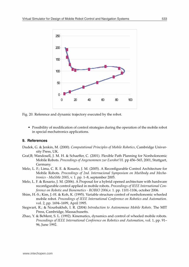
in plan XY. The Fig. 15, shows the dynamic tracing of reference and of the trajectory of themobile robot.The Fig. 16 illustrates the graphic of the trajectory error.
6. Mobile Robot Rapid Prototyping
The use of the rapid prototyping technique in mobile robotic systems differs from the tradi-tional target used in mechanics engineering and enters in new field of research and develop-ment for projects of mobile robots mechatronics systems. In this way, the rapid prototypingof these systems is associated not only with the project of the physical system, but mainlywith the experimental implementations in the fields of hardware and software of the roboticsystem. It is fundamental that the architecture of hardware of the considered system be openedand flexible in the way of effecting the necessary modifications for system optimization. Aproposal of open architecture system was presented in (Melo et al., 2003). The software of theembedded control system of the mobile robot, in the context of the rapid prototyping, can beelaborated in simulators and tested all the parameters for adjustments that makes necessaryin accordance with the physical system to be implemented, the hardware architecture, theactuators and the sensors. In this way, in the context of this work, the rapid prototyping isthen the methodology that allows the creation of a virtual environment of simulation for theproject of a controller for mobile robots. After being tested and validated in the simulator, thecontrol system is programmed in the control board memory of the mobile robot. In this way,a economy of time and material are obtained, sooner validating all the model virtually andlater operating the physical implementation of the system.
6.1 HIL (Hardware-in-the-loop) Simulation
The HIL technique of simulation is used in development and tests for real time embeddedsystems. HIL simulations provide a platform accomplish of development for adding the com-
www.intechopen.com

Mobile Robots Navigation530
0 2 4 6 8 10 12 140
0.005
0.01
0.015
0.02
0.025
0.03
0.035
0.04
0.045
Time (s)
Err
or (m
)
Cartesian Trajectory Error of Robot
Fig. 16. Error of the kinematics and dynamics trajectory of the mobile robot.
plexity of the plant under control to the tests platform. The control system is enclosed in thetests and developments through its mathematical models representations and all the respec-tive dynamic model (Melo & Rosario, 2006).The Fig. 17 illustrates the use of the HIL simulation technique for real time simulation of theconsidered mobile robotic system.
7. Experimental Validation
The Aedromo, a didactic experimental environment for mobile robots, is an ambient usedto test and validate the trajectory virtual simulator, the onboard robot control and the rapidprototyping system, all of them describe above. This environment is utilized for many othersapplications, like robotic soccer game, two or more robots interaction, etc. The supervisionand the robots movements coordination are made through a close loop architecture based ina satellite camera over the arena. The information supplied for a video camera is sent for oneor two computers for processing. The data obtained from this process are used to generate asequence of instructions that are sent for the robots. The robots receive the instructions andcarry through the actions obeying the predetermined tasks. The instructions are results ofdeveloped programmers strategies to execute the tasks and to realize the robot navigationinto the environment. The Fig. 18 depicts this environment.The trajectory to be executed by the robot, from trajectory generation software, is illustratedon Fig. 19. This trajectory allows to get parameters of comparison between the real system,represented by de robot prototype, and the virtual system. On the onboard control of the mo-bile robot was implemented a dynamic and kinematic strategy, in order to find best trajectory,avoiding obstacles on the way, like can be seen in Fig. 7.
www.intechopen.com

Virtual Simulator for Design of Mobile Robot Control and Navigation Systems 531
0 2 4 6 8 10 12 140
0.005
0.01
0.015
0.02
0.025
0.03
0.035
0.04
0.045
Time (s)
Err
or (m
)
Cartesian Trajectory Error of Robot
Fig. 17. HIL simulation for mobile robot system.
Fig. 18. The Aedromo environment.
www.intechopen.com

Mobile Robots Navigation532
0 0.5 1 1.5 2 2.5 30
0.5
1
1.5
2
2.5
3
3.5
4
Fig. 19. Best trajectory to be executed by the robot.
The graphic presented on Fig. 20 illustrates the difference of the reference trajectory, showingby the slim line with square blocs (violet) and the dynamic trajectory executed by the robot,showing by the thick line (blue).Even so the robot executes the proposed trajectory with success, we can see errors betweenthe two trajectory, mainly on curves. It was foreseen on simulator of the cartesian trajectorykinematics and dynamics of the mobile, depicted on Fig. 15 with the trajectory error on Fig. 16.These errors are predictable for the simulator because of the intrinsic dynamic characteristicof nonholonomic mobile robotics systems with differential drive wheels, which the prototypeare made, and for the PID close-loop controller of wheels velocity axles. It’s demonstrated, inthis example, the necessity and efficacy of the virtual system, proposed by this work.
8. Conclusion
The main objective of this work was to propose a generic platform for a robotic mobile system,seeking to obtain a support tool for under-graduation and graduation activities. In this way,it presents the virtual environment implementation for simulation and design conception ofsupervision and control systems for mobile robots, that are capable to operate and adaptingin different environments and conditions. This came from encountering the growing need topropose to the research that integrates the knowledge acquired in several domains that stim-ulates teamwork in order to reach a result. Another objective was to to improve knowledgein the mobile robotic area, aiming at presenting practical solutions for industrial problems,such as maintenance, supervision and transport of materials. Some promising aspects of thisplatform and simulator system are:
• Flexibility: there are a great variety of possible configurations in the implementation ofsolutions for several problems associated with mobile robots.
• Great capacity of memory storage allowing implementation of sailing strategies formaps.
• The use of the rapid prototyping technique in mobile robotic systems.
www.intechopen.com
Virtual Simulator for Design of Mobile Robot Control and Navigation Systems 533
0 0.5 1 1.5 2 2.5 30
0.5
1
1.5
2
2.5
3
3.5
4
Fig. 20. Reference and dynamic trajectory executed by the robot.
• Possibility of modification of control strategies during the operation of the mobile robotin special mechatronics applications.
9. References
Dudek, G. & Jenkin, M. (2000). Computational Principles of Mobile Robotics, Cambridge Univer-sity Press, UK.
Graf,B; Wandosell, J. M. H. & Schaeffer, C. (2001). Flexible Path Planning for NonholonomicMobile Robots. Proceedings of Angenommen zur Eurobot’01. pp 456–565, 2001, Stuttgart,Germany.
Melo, L. F.; Lima, C. R. E. & Rosario, J. M. (2005). A Reconfigurable Control Architecture forMobile Robots. Proceedings of 2nd. Internacional Symposium on Mutibody and Mecha-tronics - MuSMe 2005, v. 1. pp. 1–8, september 2005.
Melo, L. F. & Rosario, J. M. (2006). A Proposal for a hybrid opened archtecture with hardwarereconfigurable control applied in mobile robots. Proceedings of IEEE International Con-ference on Robotic and Bionemetics - ROBIO 2006,v. 1. pp. 1101-1106, october 2006.
Shim, H.-S.; Kim, J.-H. & Koh, K. (1995). Variable structure control of nonholonomic wheeledmobile robot. Proceedings of IEEE International Conference on Robotics and Automation.vol. 2, pp. 1694–1699, April 1995.
Siegwart, R.; & Nourbakhsh, I. R. (2004) Introduction to Autonomous Mobile Robots. The MITPress, Cambridge, Massachusetts.
Zhao, Y. & BeMent, S. L. (1992). Kinematics, dynamics and control of wheeled mobile robots.Proceedings of IEEE International Conference on Robotics and Automation, vol. 1, pp. 91–96, June 1992.
www.intechopen.com

Mobile Robots Navigation534
www.intechopen.com

Mobile Robots NavigationEdited by Alejandra Barrera
ISBN 978-953-307-076-6Hard cover, 666 pagesPublisher InTechPublished online 01, March, 2010Published in print edition March, 2010
InTech EuropeUniversity Campus STeP Ri Slavka Krautzeka 83/A 51000 Rijeka, Croatia Phone: +385 (51) 770 447 Fax: +385 (51) 686 166www.intechopen.com
InTech ChinaUnit 405, Office Block, Hotel Equatorial Shanghai No.65, Yan An Road (West), Shanghai, 200040, China
Phone: +86-21-62489820 Fax: +86-21-62489821
Mobile robots navigation includes different interrelated activities: (i) perception, as obtaining and interpretingsensory information; (ii) exploration, as the strategy that guides the robot to select the next direction to go; (iii)mapping, involving the construction of a spatial representation by using the sensory information perceived; (iv)localization, as the strategy to estimate the robot position within the spatial map; (v) path planning, as thestrategy to find a path towards a goal location being optimal or not; and (vi) path execution, where motoractions are determined and adapted to environmental changes. The book addresses those activities byintegrating results from the research work of several authors all over the world. Research cases aredocumented in 32 chapters organized within 7 categories next described.
How to referenceIn order to correctly reference this scholarly work, feel free to copy and paste the following:
Leonimer F Melo, Jose F Mangili Jr and Fernando C Dias Neto and Joao M Rosario (2010). Virtual Simulatorfor Design of Mobile Robot Control and Navigation Systems, Mobile Robots Navigation, Alejandra Barrera(Ed.), ISBN: 978-953-307-076-6, InTech, Available from: http://www.intechopen.com/books/mobile-robots-navigation/virtual-simulator-for-design-of-mobile-robot-control-and-navigation-systems