Embed Size (px)
Citation preview
Scientia Iranica D (2014) 21(6), 2165{2176
Sharif University of TechnologyScientia Iranica
Transactions D: Computer Science & Engineering and Electrical Engineeringwww.scientiairanica.com
Virtual ux based direct power control of shunt active�lter
S. Saidi�, R. Abbassi and S. Chebbi
LaTICE Laboratory, Higher National Engineering School of Tunis (ENSIT), University of Tunis, 5 Street Taha Hussein Mont eury1008, Tunisia.
Received 26 September 2012; received in revised form 18 November 2013; accepted 14 January 2014
KEYWORDSDirect Power Control(DPC);Virtual Flux (VF);Switching table;Shunt Active powerFilter (SAF);Harmonic currents;Phase locked loop;Self Tuning Filter(STF).
Abstract. Active �lters are e�ective solutions to eliminating harmonic pollution andimproving reactive power in the presence of nonlinear loads and unbalanced sources. Toreduce the disturbances caused by this type of load, we propose, in this paper, a newcontrol strategy of a shunt active �lter. Our method aims to improve electrical quantitybehavior in steady and dynamic states, while reducing the installing cost of the �lter,through eliminating AC line voltage sensors. This is established by Direct Power Control(DPC), based on Virtual Flux (VF) estimation of the electrical network, using a switchingfunction table. Facing disturbances a�ecting the electrical network, we have integrated aPhase Locked Loop (PLL), and have implemented and tested our new control strategy ina Matlab/Simulink environment. The results obtained show the e�ectiveness of the active�lter control algorithm in eliminating harmonic currents, and shows an improvement in thereactive power injected from nonlinear loads, which has allowed us to con�rm the robustnessof the proposed strategy.c 2014 Sharif University of Technology. All rights reserved.
1. Introduction
The use of nonlinear loads, such as diode or thyristorrecti�ers, which are usually used for electric traction,air conditioning or lighting units made from uorescenttubes, causes current and voltage distortion. Thisleads to malfunction of the device connected to thenetwork [1-3]. To overcome problems caused by theseloads, such as harmonics and reactive power consump-tion, several solutions have been proposed [4,5]. Tocompensate for the negative e�ects of nonlinear loadpresences, active power �lters are widely used [1,6,7].Compared to passive �lters which have drawbacks,including the design, which requires a thorough knowl-edge of the electrical network con�guration, and thesize, which depends on the harmonic spectrum of loadand source impedance [8,9], active �lters can both neu-
*. Corresponding author. Tel.: +216 97 828 970E-mail address: saidi [email protected] (S. Saidi)
tralize the harmonics of the upstream polluter systemand compensate for reactive power and unbalancedloads, thus, improving system e�ciency [10-12].
Among active �lters, in this paper, we are in-terested in presenting shunt �lters, whose operatingprinciple is to implement a current source for injectinga compensating current in the opposite phase to theharmonic currents generated by the nonlinear loads.Di�erent control strategies have been proposed forthese �lters [13-15]. The major disadvantage of thesestrategies is their very slow dynamic response.
This negative point has encouraged us to studythe shunt �lter, allowing direct power control. This isin order to acquire, if possible, a very high dynamicresponse [16-18]. Direct Power Control (DPC) hasbecome more widely used over the last few years in gridconnected systems, due to its advantage of controllingactive and reactive powers directly without any internalcurrent control loop or PWM modulator.
Thus, our control strategy consists of controlling
2166 S. Saidi et al./Scientia Iranica, Transactions D: Computer Science & ... 21 (2014) 2165{2176
the instantaneous active and reactive power amplitudein order to generate the command moments of theactive �lter switches to command [19,20]. It consists ofcalculating the instantaneous power, based on the esti-mated virtual ux of the electrical network. Then thereferences of active and reactive power are comparedwith their estimated values. The di�erences betweenthe references and the estimated feedback power valuesare used as inputs for the hysteresis controllers. Thedigitized output of hysteresis blocks and the sector ofvirtual ux vector position are considered as inputs forthe switching table used to select the optimum voltagevector ensuring the control of the active and reactivepowers. Besides, being present for instantaneous powercalculation, virtual ux is also is used for synchronizingactive �lter control in the electrical network. The uxis estimated from the currents and estimated supplyvoltages. These voltages are determined according tothe DC-link voltage and the switching states of theconverter arms, without the need of two voltage sensorsand a pulse width modulation stage.
This paper is organized as follows: It beginswith system con�guration and analysis of the controlalgorithm in Section 2. Next, in Section 3, particularattention has been paid to the adopted phase lockedloop. Section 4 deals with the DC-link voltage regula-tion. Section 5 is devoted to a discussion of simulationresults and the main improvements of the DPC-VFstrategy are highlighted. Finally, Section 6 containsthe main conclusions followed by the appendix andreferences.
2. System con�guration
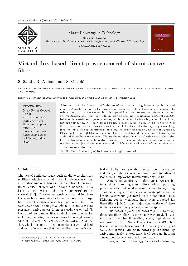
The general structure of the active �lter connected inparallel to the network (Figure 1), injects disturbedcurrents in an opposite phase and equal to those
Figure 1. Principle con�guration of a shunt APF.
absorbed by the pollutant load. This �lter type is usedto prevent disturbed currents (harmonic and reactive)circulating through the network impedance locatedupstream of the connection point of this �lter.
In this paper, the active and reactive powers havebeen considered as state variables. In particular, werecall that power pl absorbed by the load is the sumof two components: a DC component, �pl, representingthe average value of the load power, and the oscillatingcomponent, ~pl:
pl = �pl + ~pl: (1)
In order to compensate for the reactive power andeliminate the harmonic currents, our control strategyoperates under the condition in which the electrical gridshould only deliver constant instantaneous active powerat unity power factor:8<:pS = �pl
qs = 0(2)
Thus, the power ow is as shown in Figure 2. The totalload power (pl) can be provided both by the parallelactive �lter (~pl) and the electrical grid (�pl), while thereactive power quantity absorbed by the load (ql) mustbe completely fed by the active �lter:8<:pf = (pl � �pl) = (~pl)
qf = (ql � qs) = (ql)(3)
Energy storage on the DC side is via a capacitivesystem (cdc). The DC link voltage provides theharmonic component of the active power absorbed bythe load (pl), which results in compensating for lossesin the �lter. On the other hand, this supply voltagemust provide all of the reactive power absorbed by thenon-linear load (ql).
We note that the DC link voltage regulation isimportant. For this reason, our algorithm assumesthat we have a voltage sensor capable of measuring thevoltage vdc (DC link). This measure will be comparedto the reference voltage, and a controller, based on aProportional Integral (PI), treats the error in orderto enhance the command performance to maintainthe DC link voltage constant and force the injectedpowers by the �lter to follow references estimated bythe command.
3. Control algorithm
3.1. Principle of direct power controlThe basic principle of the DPC was proposed byNoguchi [11] and is similar to the well-known DirectTorque Control (DTC) for induction machines. In the
S. Saidi et al./Scientia Iranica, Transactions D: Computer Science & ... 21 (2014) 2165{2176 2167
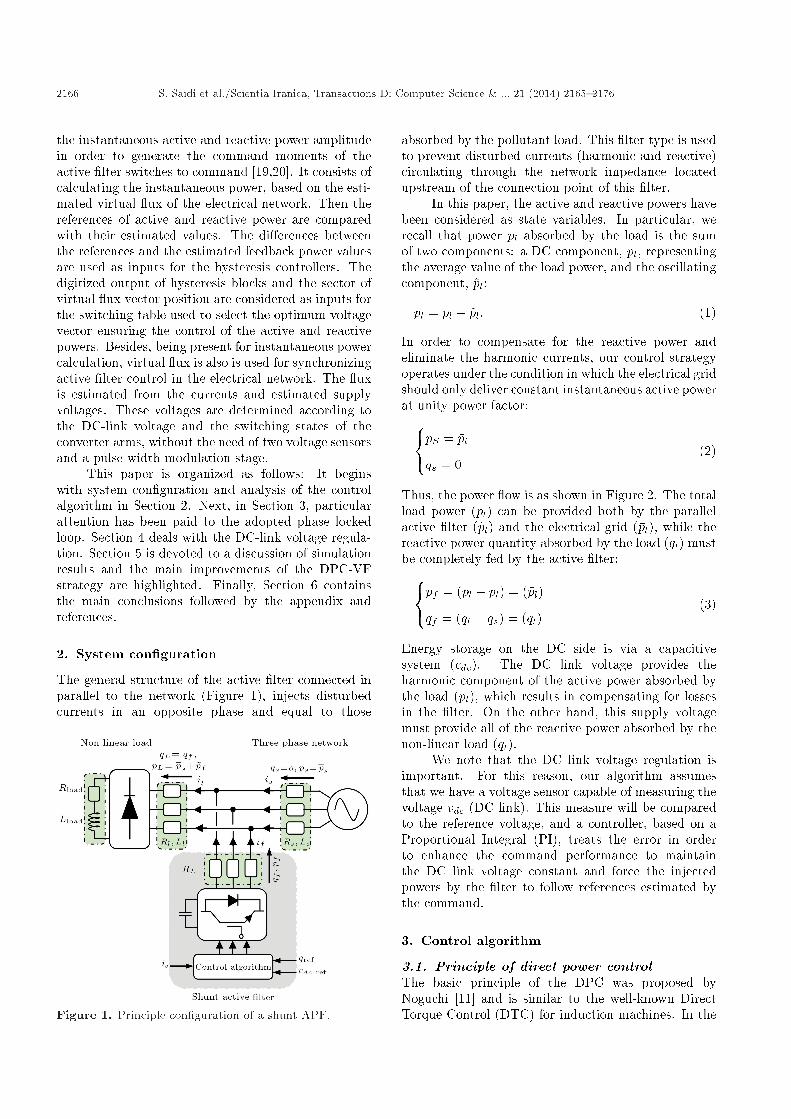
Figure 2. Structure of the command DCP-VF.
DPC, the active and reactive powers replace the torqueand the ux amplitude used as the controlled outputin the DTC. Figure 2 shows the block diagram of VF-DPC. In this con�guration, the active power command,p, is provided from a DC bus voltage controller block.By �xing the reactive power reference, q, at zero, thepower factor is kept to unity Therefore, the key pointof the VF-DPC implementation is a correct and fastestimation of the active and reactive line powers [15].The VF-DPC algorithm is based on the assumptionthat line voltage with input inductances can be noticedas the quantities of a virtual AC motor (Figure 2).The integration of the line voltage gives a virtual ux linkage of a virtual AC motor, based on themeasured DC-link voltage, vdc, and the duty cycle ofthe modulators, swa, swb and swc.
Then, the active and reactive power commands(pref and qref) are compared with the estimated valuesof p and q. The di�erences between the commandsand the estimated feedback power values, "p and "q("p = pref � p and "q = qref � q), are entered to thehysteresis controllers. The digitized signal generatedby the hysteresis controller of active power, the reactive(dp and dq), and the sector of the virtual ux vectorposition enter the switching table.
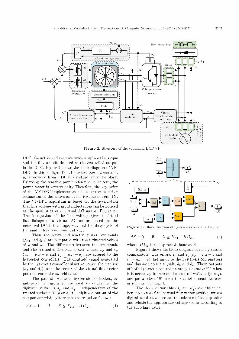
The pair of two level hysteresis controllers, asindicated in Figure 2, are used to determine thedigitized variables dp and dq. Independently of thetreated variable X (p or q), the digitized output of thecomparator with hysteresis is expressed as follows:
dX = 1 if X � Xref �HBX ; (4)
Figure 3. Block diagram of hysteresis control technique.
dX = 0 if X � Xref +HBX ; (5)
where, HBx is the hysteresis bandwidth.Figure 3 shows the block diagram of the hysteresis
comparators. The errors, "p and "q ("p = pref � p and"q = qref � q), are input to the hysteresis comparatorsand digitized to the signals, dp and dq. These outputsof both hysteresis controllers are put at state \1" whenit is necessary to increase the control variable (p or q),and put at state \0" when this variable must decreaseor remain unchanged.
The Boolean variable (dp and dq) and the mem-bership sector of the virtual ux vector position form adigital word that accesses the address of lookup tableand selects the appropriate voltage vector according tothe switching table.
2168 S. Saidi et al./Scientia Iranica, Transactions D: Computer Science & ... 21 (2014) 2165{2176
Table 1. Switching table for direct power control.
dp dq �1 �2 �3 �4 �5 �6 �7 �8 �9 �10 �11 �12
10 101 111 100 000 110 111 101 000 011 111 001 000
1 111 111 000 000 111 111 000 000 111 111 000 000
00 101 100 100 110 110 010 010 011 011 001 001 101
1 100 110 110 010 010 011 011 001 011 101 101 100
With: v1(100), v2(110), v3(010), v4(011), v5(001), v6(101), v0(000), v7(111).
Figure 4. Instantaneous voltage vectors.
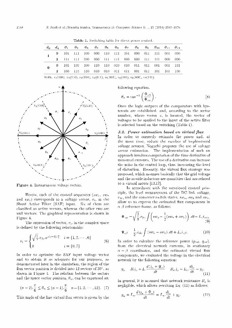
Herein, each of the control sequences (swa, swband swc) corresponds to a voltage vector, vi, at theShunt Active Filter (SAF) input. Six of them areclassi�ed as active vectors, whereas the other two arenull vectors. The graphical representation is shown inFigure 4.
The expression of vector, vi, in the complex spaceis de�ned by the following relationship:
vi =
8<:q
23 :vdc:e
j(i�1):�3 i = f1; 2; � � � ; 6g0 i = f0; 7g
(6)
In order to optimize the SAF input voltage vectorand to obtain it as adequate for our purposes, asdemonstrated later in the simulation, the region of the ux vector position is divided into 12 sectors of 30�, asshown in Figure 4. The relation between the sectorsand the space vector position, �n, can be expressed as:
(n� 2):�6� �n � (n� 1):
�6
n=f1; 2; � � � ; 12g: (7)
This angle of the line virtual ux vector is given by the
following equation:
�n = tan�1�
s�
s�
�: (8)
Once the logic outputs of the comparators with hys-teresis are established, and, according to the sectornumber, where vector vi is located, the vector ofvoltages to be applied to the input of the active �lteris selected based on the switching (Table 1).
3.2. Power estimation based on virtual uxIn order to correctly estimate the power and, atthe same time, reduce the number of implementedvoltage sensors, Noguchi proposes the use of voltagevector estimation. The implementation of such anapproach involves computation of the time derivative ofmeasured currents. The use of a derivative can increasethe noise in the control loop, thus, increasing the levelof distortion. Recently, the virtual ux strategy wasproposed, which assumes basically that the grid voltageand the ac-side inductors are quantities that are relatedto a virtual motor [13,17].
In accordance with the mentioned control prin-ciple, the level measurement of the DC link voltage,vdc, and the converter switch states, swa, swb and swc,allow us to express the estimated ux components in�-� reference frame, as follows:
s� =r
23:vdc
Z �swa� 1
2(swb + swc)
�:dt+ Lsis�;
(9)
s� =12:vdc
Z(swb � swc) :dt+ Lsis� : (10)
In order to calculate the reference power (pref, qref),from the electrical network currents, in stationary� � � coordinates, and the estimated virtual uxcomponents, we evaluated the voltage in the electricalnetwork by the following equation:
us = R:is + L:d (is + s)
dt= Rs:is + Ls:
disdt
+ ul:(11)
In general, it is assumed that network resistance Rs isnegligible, which allows rewriting Eq. (11) as follows:
us = Ls:d (is + s)
dt= Ls:
disdt
+ ul: (12)
S. Saidi et al./Scientia Iranica, Transactions D: Computer Science & ... 21 (2014) 2165{2176 2169
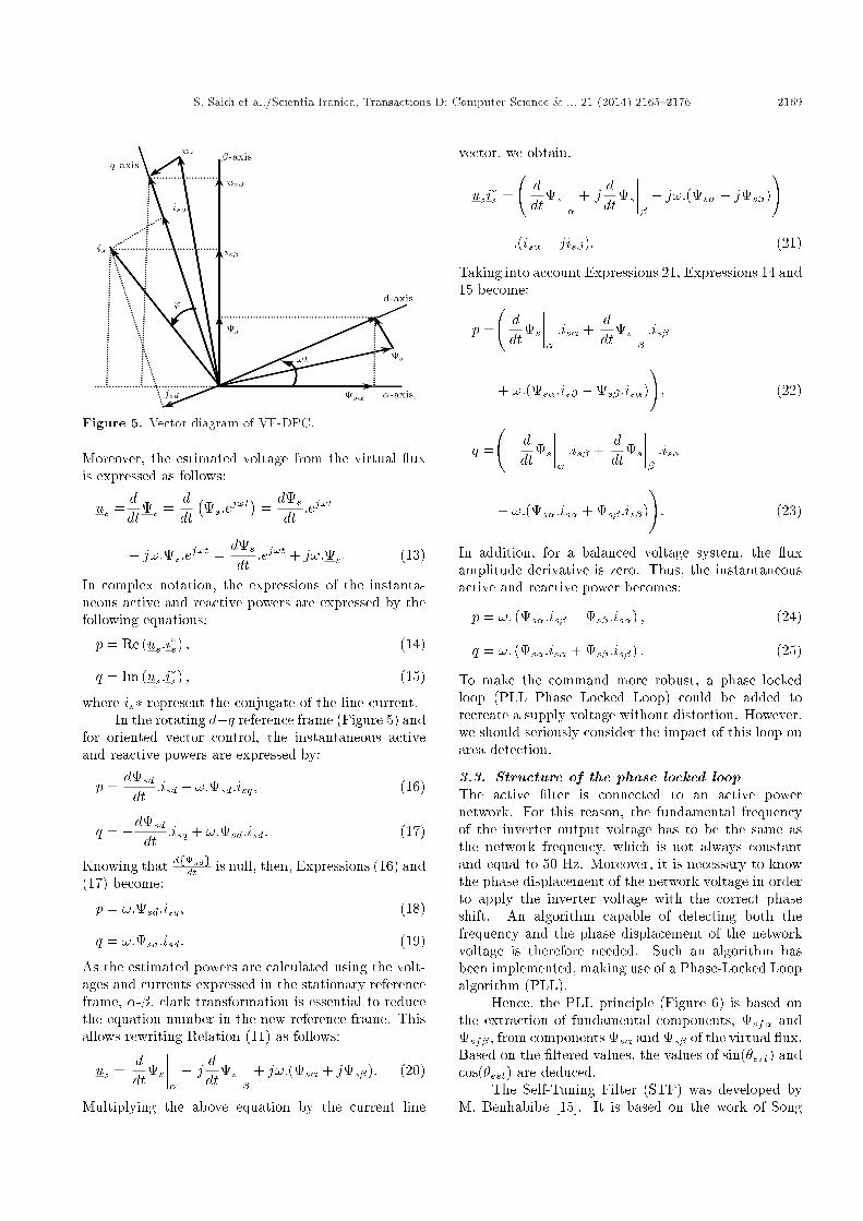
Figure 5. Vector diagram of VF-DPC.
Moreover, the estimated voltage from the virtual uxis expressed as follows:
us =ddt
s =ddt�s:ej!t
�=ds
dt:ej!t
+ j!:s:ej!t =ds
dt:ej!t + j!:s: (13)
In complex notation, the expressions of the instanta-neous active and reactive powers are expressed by thefollowing equations:
p = Re (us:i�s) ; (14)
q = Im (us:i�s) ; (15)
where is� represent the conjugate of the line current.In the rotating d�q reference frame (Figure 5) and
for oriented vector control, the instantaneous activeand reactive powers are expressed by:
p =dsd
dt:isd + !:sd:isq; (16)
q = �dsd
dt:isq + !:sd:isd: (17)
Knowing that dfsdgdt is null, then, Expressions (16) and
(17) become:
p = !:sd:isq; (18)
q = !:sd:isd: (19)
As the estimated powers are calculated using the volt-ages and currents expressed in the stationary referenceframe, �-�, clark transformation is essential to reducethe equation number in the new reference frame. Thisallows rewriting Relation (11) as follows:
us =ddt
s
�����
+ jddt
s
�����
+ j!:(s� + js�): (20)
Multiplying the above equation by the current line
vector, we obtain:
usi�s =
ddt
s
�����
+ jddt
s
�����
+ j!:(s� + js�)
!:(is� � jis�): (21)
Taking into account Expressions 21, Expressions 14 and15 become:
p =
ddt
s
�����:is� +
ddt
s
�����:is�
+ !:(s�:is� �s� :is�)
!; (22)
q =
� ddt
s
�����:is� +
ddt
s
�����:is�
+ !:(s�:is� + s� :is�)
!: (23)
In addition, for a balanced voltage system, the uxamplitude derivative is zero. Thus, the instantaneousactive and reactive power becomes:
p = !: (s�:is� �s� :is�) ; (24)
q = !: (s�:is� + s� :is�) : (25)
To make the command more robust, a phase lockedloop (PLL Phase Locked Loop) could be added torecreate a supply voltage without distortion. However,we should seriously consider the impact of this loop onarea detection.
3.3. Structure of the phase locked loopThe active �lter is connected to an active powernetwork. For this reason, the fundamental frequencyof the inverter output voltage has to be the same asthe network frequency, which is not always constantand equal to 50 Hz. Moreover, it is necessary to knowthe phase displacement of the network voltage in orderto apply the inverter voltage with the correct phaseshift. An algorithm capable of detecting both thefrequency and the phase displacement of the networkvoltage is therefore needed. Such an algorithm hasbeen implemented, making use of a Phase-Locked Loopalgorithm (PLL).
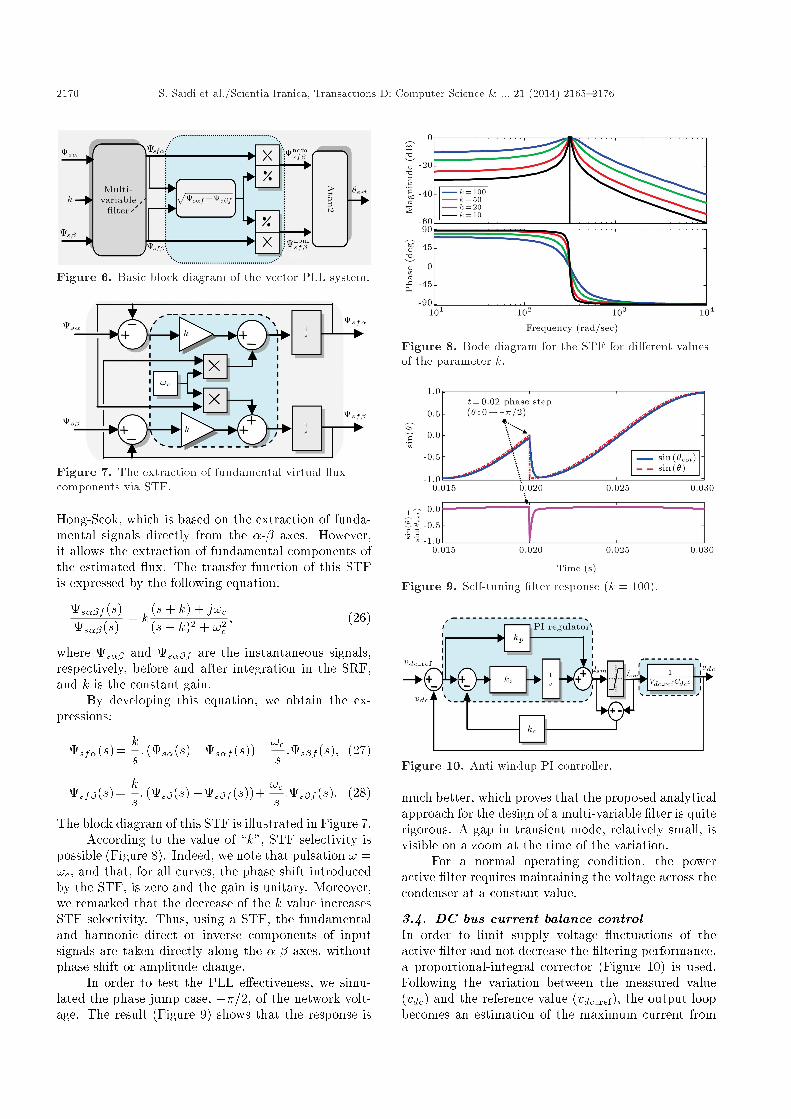
Hence, the PLL principle (Figure 6) is based onthe extraction of fundamental components, sf� andsf� , from components s� and s� of the virtual ux.Based on the �ltered values, the values of sin(�est) andcos(�est) are deduced.
The Self-Tuning Filter (STF) was developed byM. Benhabibe [15]. It is based on the work of Song
2170 S. Saidi et al./Scientia Iranica, Transactions D: Computer Science & ... 21 (2014) 2165{2176
Figure 6. Basic block diagram of the vector PLL system.
Figure 7. The extraction of fundamental virtual uxcomponents via STF.
Hong-Scok, which is based on the extraction of funda-mental signals directly from the �-� axes. However,it allows the extraction of fundamental components ofthe estimated ux. The transfer function of this STFis expressed by the following equation:
s��f (s)s��(s)
= k(s+ k) + j!c(s+ k)2 + !2
c; (26)
where s�� and s��f are the instantaneous signals,respectively, before and after integration in the SRF,and k is the constant gain.
By developing this equation, we obtain the ex-pressions:
sf�(s)=ks: (s�(s)�s�f (s))� !c
s:s�f (s); (27)
sf�(s)=ks: (s�(s)�s�f (s))+
!cs:s�f (s): (28)
The block diagram of this STF is illustrated in Figure 7.According to the value of \k", STF selectivity is
possible (Figure 8). Indeed, we note that pulsation ! =!c, and that, for all curves, the phase shift introducedby the STF, is zero and the gain is unitary. Moreover,we remarked that the decrease of the k value increasesSTF selectivity. Thus, using a STF, the fundamentaland harmonic direct or inverse components of inputsignals are taken directly along the �-� axes, withoutphase shift or amplitude change.
In order to test the PLL e�ectiveness, we simu-lated the phase jump case, ��=2, of the network volt-age. The result (Figure 9) shows that the response is
Figure 8. Bode diagram for the STF for di�erent valuesof the parameter k.
Figure 9. Self-tuning �lter response (k = 100).
Figure 10. Anti-windup PI controller.
much better, which proves that the proposed analyticalapproach for the design of a multi-variable �lter is quiterigorous. A gap in transient mode, relatively small, isvisible on a zoom at the time of the variation.
For a normal operating condition, the poweractive �lter requires maintaining the voltage across thecondenser at a constant value.
3.4. DC bus current balance controlIn order to limit supply voltage uctuations of theactive �lter and not decrease the �ltering performance,a proportional-integral corrector (Figure 10) is used.Following the variation between the measured value(vdc) and the reference value (vdc ref), the output loopbecomes an estimation of the maximum current from
S. Saidi et al./Scientia Iranica, Transactions D: Computer Science & ... 21 (2014) 2165{2176 2171
the source (Ism). This current is used to calculate thereference power (pref) requested by the active �lter andthe losses caused by the power active �lter.
Taking into account the PI regulator transferfunction and that of the DC side, the transfer functionof the control loop is:
vdcvdc ref
=3v2s(1 + �n:s)
(vsm:cdc:�i:vdc ref)s2 + (3�n:v2s):s+ 3v2
s
=3v2s(1+�n:s)
vsm:cdc:�i:vdc ref
s2 + 2�!c:s+ !2c; (29)
with, !c, the cuto� frequency, expressed by:
!c =
s3v2s
vsm:cdc:�i:vdc ref; (30)
and, �, the damping coe�cient, given by:
� =3�n:v2
s2!c:vsm:cdc:�i:vdc ref
=p
3�n:vs2pvsm:cdc:�i:vdc ref
:(31)
This function can be set as follows:vdcvdc ref
=!2c + (2:!c:�:�n):ss2 + 2�!c:s+ !2
c: (32)
In order to realize a good trade-o� between stabilityand dynamic performance, one can choose � = 0:7 and!c = 2�fc. Finally, we deduce the time constants �iand �n:8><>:�i = 3v2
svsm:cdc:!2
c :vdc ref
�n = 2�:pvsm:cdc:�i:vdc refp3:vs
(33)
where:
� � is the damping coe�cient and !c is the cut-o�frequency;
� kp, ki, �i and �n are the proportional constant, theintegral constant, the integration time constant andthe time constant of the PI controller, respectively.
It is important to note that the calculationof the integral component takes into account thelimitation on the order;
� If error (vdc ref � vdc) is positive for a certainperiod of time, control signal Ism saturates to themaximum value, Ism;
� If the error remains positive after the saturation ofIsm, the integrator continues to accumulate an errorthat will be di�cult to cancel in a reasonable periodof time. This can causes a signi�cant error in output,and even system instability.
To avoid this e�ect, we have added a loop using anew error signal de�ned as the di�erence between thecontroller output, Ism, and the actuator output, Ism,weighted by a gain, kc.
4. Simulation results
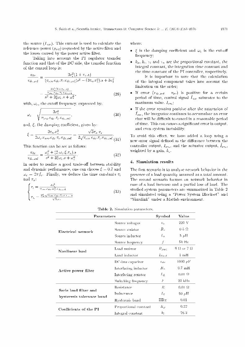
The �rst scenario is to analyze network behavior in thepresence of a load quantity assumed as a total amount.The second scenario focuses on network behavior incase of a load increase and a partial loss of load. Thestudied system parameters are summarized in Table 2and simulated using a \Power System Blockset" and\Simulink" under a Matlab environment.
Table 2. Simulation parameters.
Parameters Symbol Value
Electrical network
Source voltages vs 220 V
Source resistor Rs 0.5
Source inductor Ls 5 �H
Source frequency f 50 Hz
Nonlinear loadLoad resistor Rload 9 or 7
Load inductor Lload 1 mH
Active power �lter
DC-bus capacitor cdc 1600 �F
Interfacing inductor RL 0.7 mH
Interfacing resistor LL 0.01
Switching frequency F 20 kHz
Serie load �lter and
hysteresis tolerance band
Resistance R 0.01
Inductance Ll 50 �H
Hysteresis band HBX 0.01
Coe�cients of the PIProportional constant Kp 0.22
Integral constant ki 76.2
2172 S. Saidi et al./Scientia Iranica, Transactions D: Computer Science & ... 21 (2014) 2165{2176
Figure 11. (a) DC side capacitor voltage, (b) �lterscurrent waveforms, and (c) instantaneous active powerswaveforms at the source side.
4.1. First scenarioIn the presence of a nonlinear load in the Gra�etz bridgewith six diodes connected to a three-phase network,as shown in Figure 1, we simulated network behaviorfollowing the insertion of a parallel active �lter at timet = 0:02 s.
The results show that after the integration of theproposed parallel active �lter, the DC-link bus voltage(Figure 11(a)) reaches its reference value imposed bythe control algorithm. Furthermore, we note that, evenwith low ripple, the answer is better, thanks to the useof the twelve sectors table. Moreover, we note thatthe reactive power and harmonic component of activepower (Figure 11(c) and (d)) are zero, con�rming theunity of the power factor.
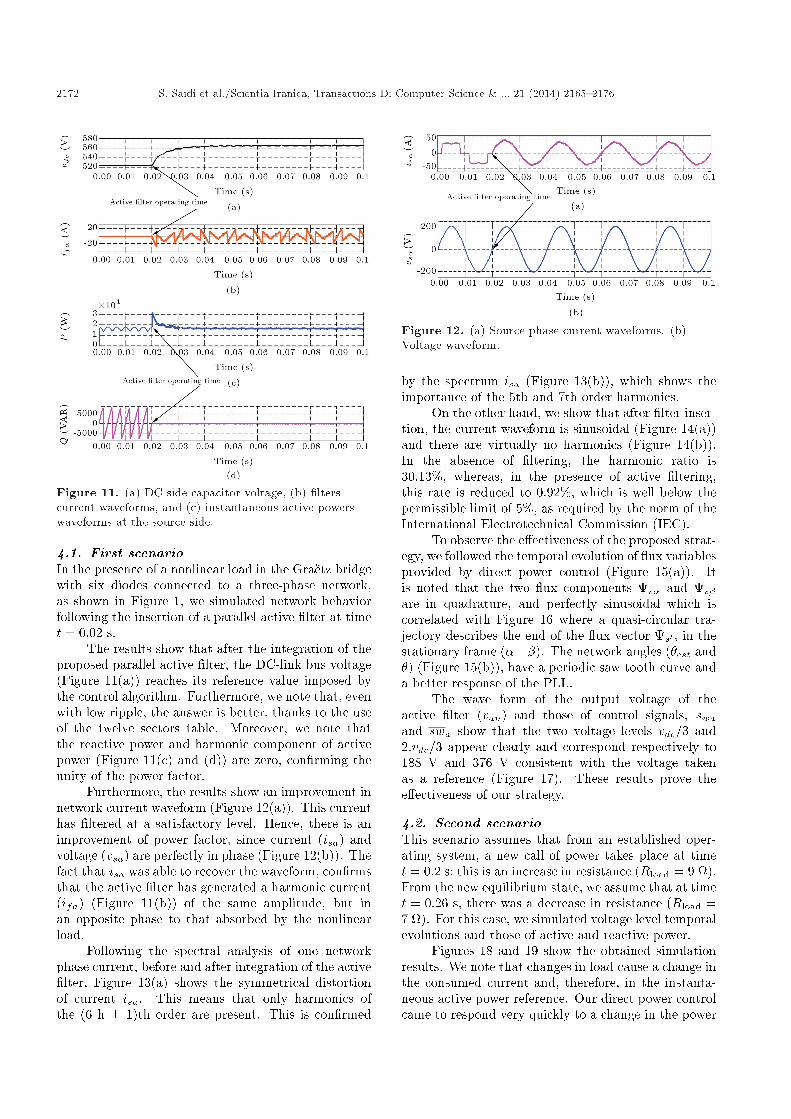
Furthermore, the results show an improvement innetwork current waveform (Figure 12(a)). This currenthas �ltered at a satisfactory level. Hence, there is animprovement of power factor, since current (isa) andvoltage (vsa) are perfectly in phase (Figure 12(b)). Thefact that isa was able to recover the waveform, con�rmsthat the active �lter has generated a harmonic current(ifa) (Figure 11(b)) of the same amplitude, but inan opposite phase to that absorbed by the nonlinearload.
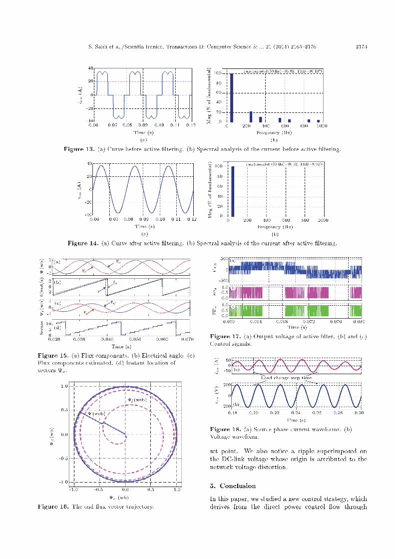
Following the spectral analysis of one networkphase current, before and after integration of the active�lter, Figure 13(a) shows the symmetrical distortionof current isa. This means that only harmonics ofthe (6 h � 1)th order are present. This is con�rmed
Figure 12. (a) Source phase current waveforms. (b)Voltage waveform.
by the spectrum isa (Figure 13(b)), which shows theimportance of the 5th and 7th order harmonics.
On the other hand, we show that after �lter inser-tion, the current waveform is sinusoidal (Figure 14(a))and there are virtually no harmonics (Figure 14(b)).In the absence of �ltering, the harmonic ratio is30.13%, whereas, in the presence of active �ltering,this rate is reduced to 0.92%, which is well below thepermissible limit of 5%, as required by the norm of theInternational Electrotechnical Commission (IEC).
To observe the e�ectiveness of the proposed strat-egy, we followed the temporal evolution of ux variablesprovided by direct power control (Figure 15(a)). Itis noted that the two ux components s� and s�are in quadrature, and perfectly sinusoidal which iscorrelated with Figure 16 where a quasi-circular tra-jectory describes the end of the ux vector s0 , in thestationary frame (���). The network angles (�est and�) (Figure 15(b)), have a periodic saw tooth curve anda better response of the PLL.
The wave form of the output voltage of theactive �lter (van) and those of control signals, swaand swa show that the two voltage levels vdc=3 and2:vdc=3 appear clearly and correspond respectively to188 V and 376 V consistent with the voltage takenas a reference (Figure 17). These results prove thee�ectiveness of our strategy.
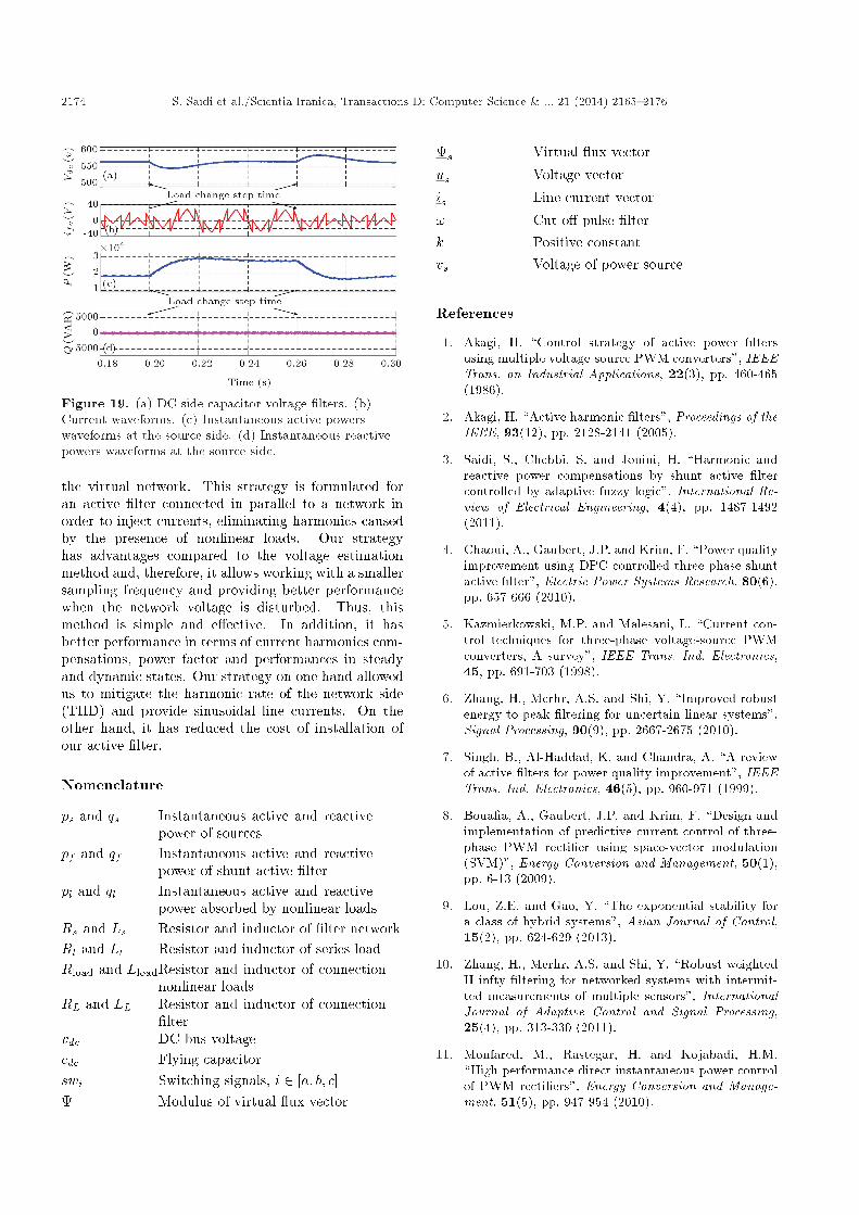
4.2. Second scenarioThis scenario assumes that from an established oper-ating system, a new call of power takes place at timet = 0:2 s; this is an increase in resistance (Rload = 9 ).From the new equilibrium state, we assume that at timet = 0:26 s, there was a decrease in resistance (Rload =7 ). For this case, we simulated voltage level temporalevolutions and those of active and reactive power.
Figures 18 and 19 show the obtained simulationresults. We note that changes in load cause a change inthe consumed current and, therefore, in the instanta-neous active power reference. Our direct power controlcame to respond very quickly to a change in the power
S. Saidi et al./Scientia Iranica, Transactions D: Computer Science & ... 21 (2014) 2165{2176 2173
Figure 13. (a) Curve before active �ltering. (b) Spectral analysis of the current before active �ltering.
Figure 14. (a) Curve after active �ltering. (b) Spectral analysis of the current after active �ltering.
Figure 15. (a) Flux components. (b) Electrical angle. (c)Flux components estimated. (d) Instant location ofsectors s.
Figure 16. The end ux vector trajectory.
Figure 17. (a) Output voltage of active �lter. (b) and (c)Control signals.
Figure 18. (a) Source phase current waveforms. (b)Voltage waveform.
set point. We also notice a ripple superimposed onthe DC-link voltage whose origin is attributed to thenetwork voltage distortion.
5. Conclusion
In this paper, we studied a new control strategy, whichderives from the direct power control ow through
2174 S. Saidi et al./Scientia Iranica, Transactions D: Computer Science & ... 21 (2014) 2165{2176
Figure 19. (a) DC side capacitor voltage �lters. (b)Current waveforms. (c) Instantaneous active powerswaveforms at the source side. (d) Instantaneous reactivepowers waveforms at the source side.
the virtual network. This strategy is formulated foran active �lter connected in parallel to a network inorder to inject currents, eliminating harmonics causedby the presence of nonlinear loads. Our strategyhas advantages compared to the voltage estimationmethod and, therefore, it allows working with a smallersampling frequency and providing better performancewhen the network voltage is disturbed. Thus, thismethod is simple and e�ective. In addition, it hasbetter performance in terms of current harmonics com-pensations, power factor and performances in steadyand dynamic states. Our strategy on one hand allowedus to mitigate the harmonic rate of the network side(THD) and provide sinusoidal line currents. On theother hand, it has reduced the cost of installation ofour active �lter.
Nomenclature
ps and qs Instantaneous active and reactivepower of sources
pf and qf Instantaneous active and reactivepower of shunt active �lter
pl and ql Instantaneous active and reactivepower absorbed by nonlinear loads
Rs and Ls Resistor and inductor of �lter networkRl and Ll Resistor and inductor of series loadRload and LloadResistor and inductor of connection
nonlinear loadsRL and LL Resistor and inductor of connection
�ltervdc DC bus voltagecdc Flying capacitorswi Switching signals, i 2 [a; b; c] Modulus of virtual ux vector
s Virtual ux vectorus Voltage vectoris Line current vector! Cut o� pulse �lterk Positive constantvs Voltage of power source
References
1. Akagi, H. \Control strategy of active power �ltersusing multiple voltage-source PWM converters", IEEETrans. on Industrial Applications, 22(3), pp. 460-465(1986).
2. Akagi, H. \Active harmonic �lters", Proceedings of theIEEE, 93(12), pp. 2128-2141 (2005).
3. Saidi, S., Chebbi, S. and Jouini, H. \Harmonic andreactive power compensations by shunt active �ltercontrolled by adaptive fuzzy logic", International Re-view of Electrical Engineering, 4(4), pp. 1487-1492(2011).
4. Chaoui, A., Gaubert, J.P. and Krim, F. \Power qualityimprovement using DPC controlled three-phase shuntactive �lter", Electric Power Systems Research, 80(6),pp. 657-666 (2010).
5. Kazmierkowski, M.P. and Malesani, L. \Current con-trol techniques for three-phase voltage-source PWMconverters, A survey", IEEE Trans. Ind. Electronics,45, pp. 691-703 (1998).
6. Zhang, H., Merhr, A.S. and Shi, Y. \Improved robustenergy-to-peak �ltering for uncertain linear systems",Signal Processing, 90(9), pp. 2667-2675 (2010).
7. Singh, B., Al-Haddad, K. and Chandra, A. \A reviewof active �lters for power quality improvement", IEEETrans. Ind. Electronics, 46(5), pp. 960-971 (1999).
8. Boua�a, A., Gaubert, J.P. and Krim, F. \Design andimplementation of predictive current control of three-phase PWM recti�er using space-vector modulation(SVM)", Energy Conversion and Management, 50(1),pp. 6-13 (2009).
9. Lou, Z.E. and Gao, Y. \The exponential stability fora class of hybrid systems", Asian Journal of Control,15(2), pp. 624-629 (2013).
10. Zhang, H., Merhr, A.S. and Shi, Y. \Robust weightedH infty �ltering for networked systems with intermit-ted measurements of multiple sensors", InternationalJournal of Adaptive Control and Signal Processing,25(4), pp. 313-330 (2011).
11. Monfared, M., Rastegar, H. and Kojabadi, H.M.\High performance direct instantaneous power controlof PWM recti�ers", Energy Conversion and Manage-ment, 51(5), pp. 947-954 (2010).
S. Saidi et al./Scientia Iranica, Transactions D: Computer Science & ... 21 (2014) 2165{2176 2175
12. Zhang, H., Merhr, A.S. and Shi, Y. \On H in�nity �l-tering for discrete-time Takagi-Sugeno fuzzy systems",IEEE Trans. Fuzzy Systems, 20(2), pp. 396-401 (2012).
13. Malinowski, M., Kazmierkowski, M.P., Hansen, S.,Blaabjerg, F. and Marques, G.D. \Virtual- ux-baseddirect power control of three-phase PWM recti�ers",IEEE Trans. Ind. Applications, 37(4), pp. 1019-1027(2001).
14. Omeiri, A., Haddouche, A., Zellouma, L. and Saad, S.\A three-phase shunt active power �lter for currentsharmonics suppression and reactive power compensa-tion", Asian Journal of Information Technology, 5(12),pp. 1454-1457 (2006).
15. Abdusalam, M., Poure, P., Karimi, S. and Saadate,S. \New digital reference current generation for shuntactive power �lter under distorted voltage conditions",Electric Power Systems Research, 79(5), pp. 759-765(2009).
16. Wang, D.J. and Gao, X.L. \Stability margins and H1co-design with fractional-order PID controllers", AsianJournal of Control, 15(3), pp. 691-697 (2013).
17. Noguchi, T., Tomiki, H., Kondo, S. and Takahashi,I. \Direct power control of PWM converter withoutpower-source voltage sensors", IEEE Trans. Ind. Ap-plications, 34(3), pp. 473-479 (1998).
18. Hyosung, K., Blaabjerg, F., Bak-Jensen, B. and Jaeho,C. \Instantaneous power compensation in three-phasesystems by using p-q-r theory", IEEE Transaction onPower Electronics, 17(5), pp. 701-710 (2002).
19. Sato, A. and Noguchi, T. \Voltage-source PWMrecti�er-inverter based on direct power control and its
operation characteristics", IEEE Trans. Ind. PowerElectronics, 26(5), pp. 1559- 1567 (2011).
20. Zhang, H., Merhr, A.S. and Shi, Y. \Robust energy-to-peak �ltering for networked systems with time-varyingdelays and randomly missing data", IET ControlTheory & Applications, 4(12), pp. 2921-2936 (2010).
Appendix
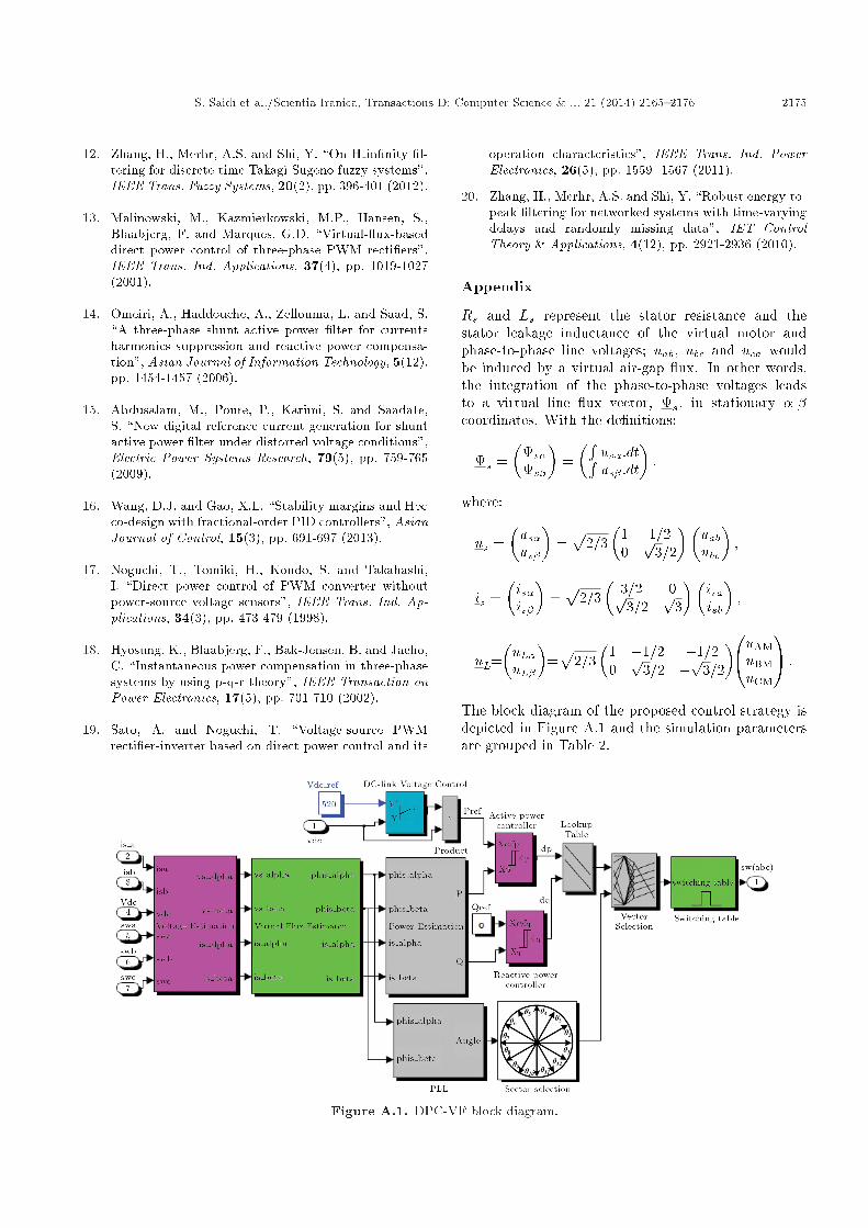
Rs and Ls represent the stator resistance and thestator leakage inductance of the virtual motor andphase-to-phase line voltages; uab, ubc and uca wouldbe induced by a virtual air-gap ux. In other words,the integration of the phase-to-phase voltages leadsto a virtual line ux vector, s, in stationary �-�coordinates. With the de�nitions:
s =�
s�s�
�=�R
us�:dtRus� :dt
�;
where:
us =�us�us�
�=p
2=3�
1 1=20p
3=2
��uabubc
�;
is =�is�is�
�=p
2=3�
3=2 0p3=2
p3
��isaisb
�;
uL=�uL�uL�
�=p
2=3�
1 �1=2 �1=20p
3=2 �p3=2
�0@uAMuBMuCM
1A :
The block diagram of the proposed control strategy isdepicted in Figure A.1 and the simulation parametersare grouped in Table 2.
Figure A.1. DPC-VF block diagram.

2176 S. Saidi et al./Scientia Iranica, Transactions D: Computer Science & ... 21 (2014) 2165{2176
Biographies
Salem Saidi received the MS degree in ElectricalEngineering from Higher National Engineering Schoolof Tunis - Tunisia (ENSIT), Tunis University, in 2009.Currently, he is preparing a PhD degree thesis onelectrical networks and active power �ltering in theLaTICE laboratory. He is interested in power elec-tronics and machine modeling, control induction Motordrives, Pulse Width Modulation, Multilevel inverterand active �lter.
Rabeh Abbassi received the PhD degree in electri-cal engineering from the Higher National EngineeringSchool of Tunis (ENSIT), Tunis University, Tunisia, in
2014. Since 2007, he has been with LaTICE laboratory.His research interests include renewable energies, smartgrid, wind turbines control, photovoltaic systems,storage systems, integration of distributed generation,control of power converters and power conditioning. Heis also an Assistant Professor with the Department ofElectrical Engineering at ISSATK.
Souad Chebbi obtained her PhD degree in 1983 inElectrical Engineering. She is head of the Laboratory ofTechnologies of Information and Communication andElectrical Engineering (LaTICE), at the Higher Na-tional Engineering School of Tunis (ENSIT), Universityof Tunisia. Her research is in the areas of electricalnetworks and electrical systems.