Embed Size (px)
Citation preview
© 2010 ANSYS, Inc. All rights reserved. 1 ANSYS, Inc. Proprietary© 2010 ANSYS, Inc. All rights reserved. 1 ANSYS, Inc. Proprietary
Justin Penrose
ANSYS UK Ltd
Seminar
30th November 2010
Engineering Simulation
Software for the Offshore,
Marine and Wave/Tidal
Renewable Energy Industries
Viscous CFD
applications
© 2010 ANSYS, Inc. All rights reserved. 2 ANSYS, Inc. Proprietary
• Introduction to viscous CFD
• CFD capabilities
• Introduction to CFD applications
• ANSYS CFD applications (Part 1)– Drag and motion simulation
• Guest presentation– BMT Fluid Mechanics
• Hydrodynamic loading on a subsea pipeline
• Ballast tank sloshing in hurricanes
• Submarine hydrodynamics
• ANSYS CFD applications (Part 2)• OWCs, tidal turbines
• Guest presentation– Cardiff University
• Tidal stream energy
• ANSYS CFD applications (Part 3)– Farm layouts
Agenda
© 2010 ANSYS, Inc. All rights reserved. 3 ANSYS, Inc. Proprietary
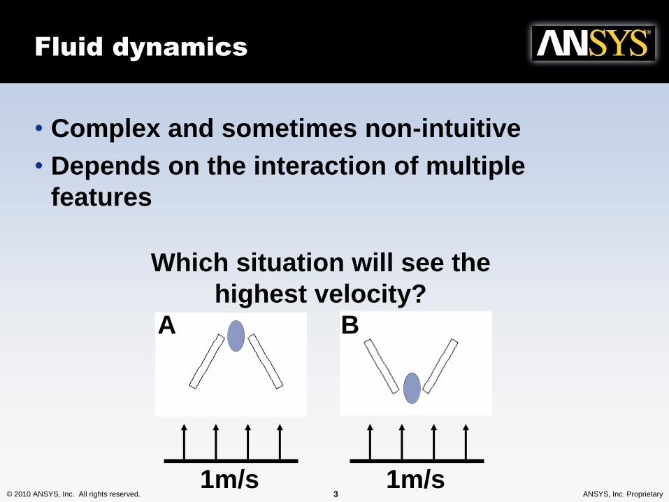
Fluid dynamics
• Complex and sometimes non-intuitive
• Depends on the interaction of multiple
features
1m/s 1m/s
Which situation will see the
highest velocity?
A B
© 2010 ANSYS, Inc. All rights reserved. 4 ANSYS, Inc. Proprietary
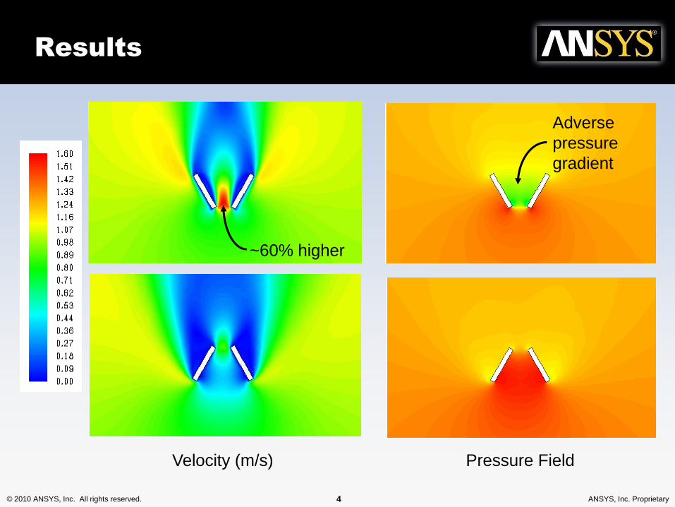
Results
Velocity (m/s) Pressure Field
Adverse
pressure
gradient
~60% higher
© 2010 ANSYS, Inc. All rights reserved. 5 ANSYS, Inc. Proprietary
What is CFD?
• Computational Fluid Dynamics (CFD)…
• Flow simulation allows a prototype to be modelled on
the PC workstation
– Complementing physical testing
• CFD can be used on
– Any geometry at any scale
– Most flow physics including free-surfaces and motion
…is the science of predicting fluid flow, heat transfer,
mass transfer and related phenomena by solving the
mathematical equations which govern these physical
processes, using a numerical approach (i.e. on a
computer) including viscous effects
© 2010 ANSYS, Inc. All rights reserved. 6 ANSYS, Inc. Proprietary
Introduction to CFD applications
• Many applications for fluid flow analysis with viscous
CFD
– Hydrodynamic characterisation and loading of floating
and submerged hull forms, structures and devices
• Viscous drag, form drag
• Wave-making, sea-keeping
– Motion response
• Vortex induced vibration
– Added mass and damping analysis
– Tidal turbine hydraulic performance
– Tidal turbine farm layout and wake-effect investigation
– Providing fluid loading results for fluid-structure-
interaction assessment
© 2010 ANSYS, Inc. All rights reserved. 7 ANSYS, Inc. Proprietary
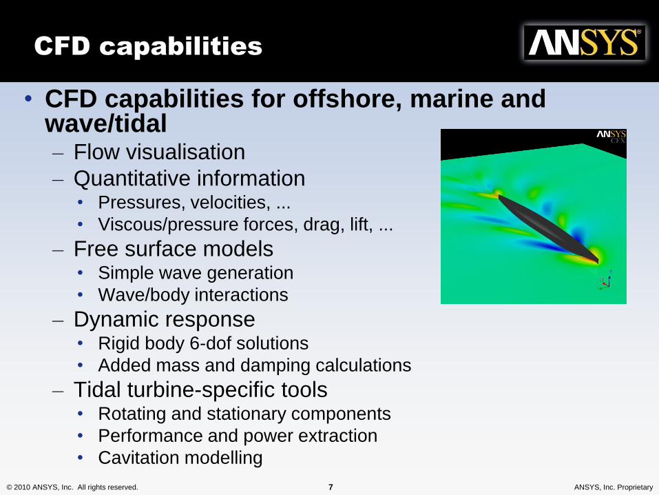
• CFD capabilities for offshore, marine and wave/tidal– Flow visualisation
– Quantitative information• Pressures, velocities, ...
• Viscous/pressure forces, drag, lift, ...
– Free surface models• Simple wave generation
• Wave/body interactions
– Dynamic response• Rigid body 6-dof solutions
• Added mass and damping calculations
– Tidal turbine-specific tools• Rotating and stationary components
• Performance and power extraction
• Cavitation modelling
CFD capabilities
© 2010 ANSYS, Inc. All rights reserved. 8 ANSYS, Inc. Proprietary© 2010 ANSYS, Inc. All rights reserved. 8 ANSYS, Inc. Proprietary
Hydrodynamic
characterisation
© 2010 ANSYS, Inc. All rights reserved. 9 ANSYS, Inc. Proprietary
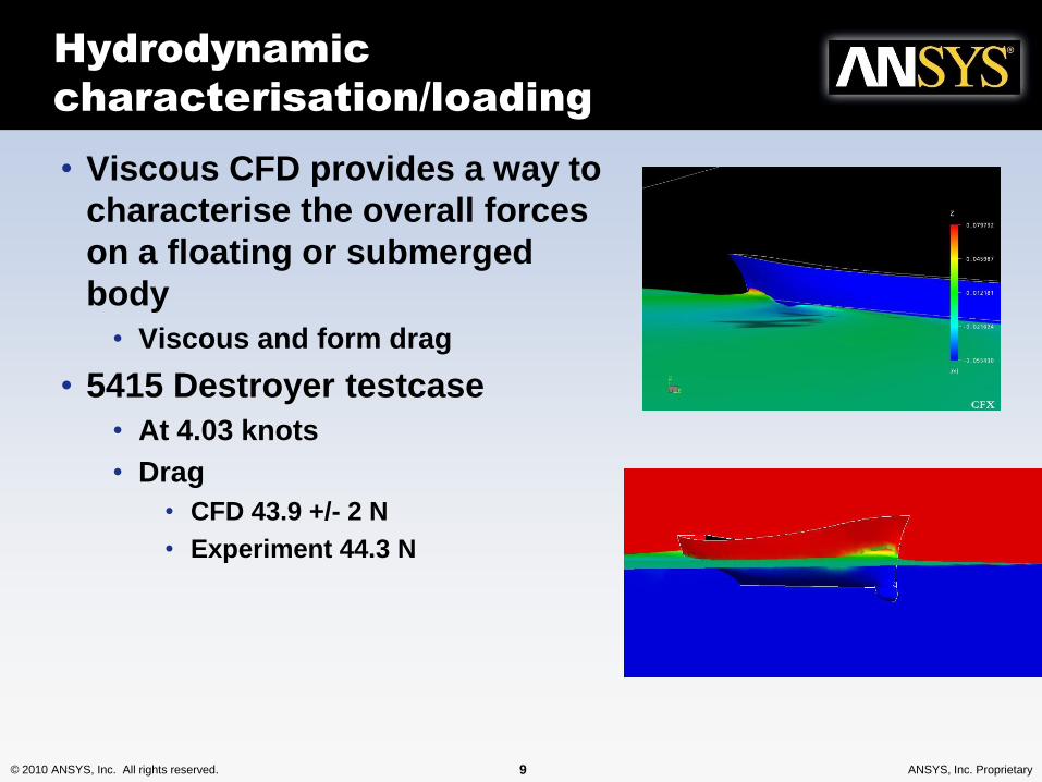
Hydrodynamic
characterisation/loading
• Viscous CFD provides a way to
characterise the overall forces
on a floating or submerged
body
• Viscous and form drag
• 5415 Destroyer testcase
• At 4.03 knots
• Drag
• CFD 43.9 +/- 2 N
• Experiment 44.3 N
© 2010 ANSYS, Inc. All rights reserved. 10 ANSYS, Inc. Proprietary
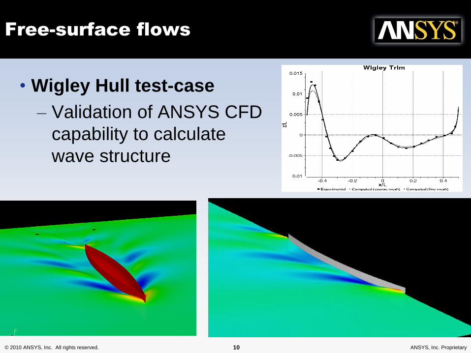
Free-surface flows
• Wigley Hull test-case
– Validation of ANSYS CFD
capability to calculate
wave structure
© 2010 ANSYS, Inc. All rights reserved. 11 ANSYS, Inc. Proprietary
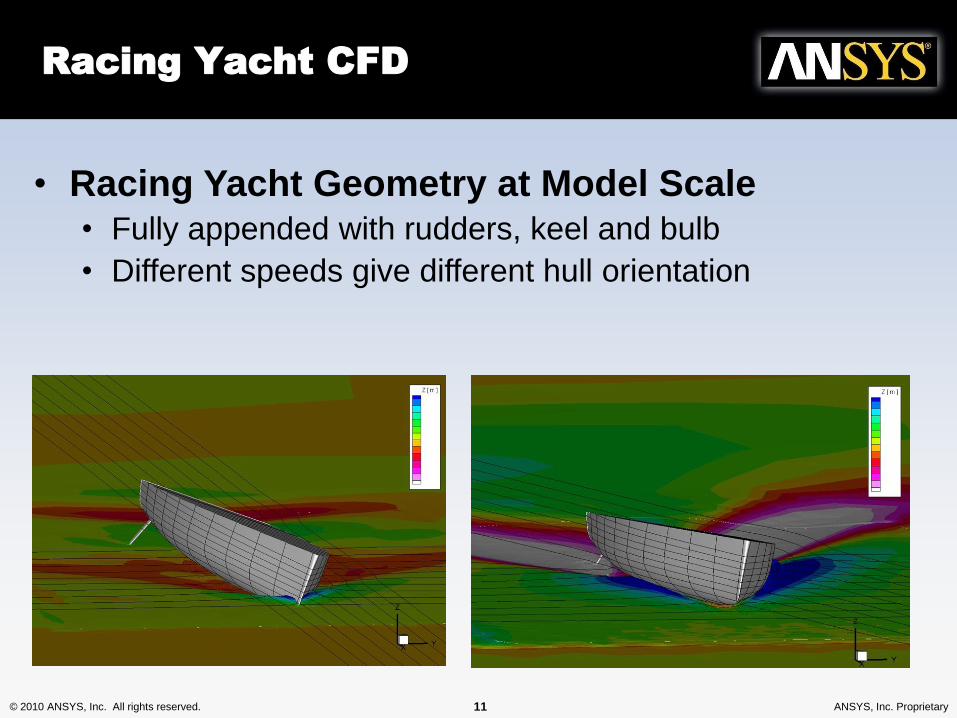
Racing Yacht CFD
• Racing Yacht Geometry at Model Scale• Fully appended with rudders, keel and bulb
• Different speeds give different hull orientation
© 2010 ANSYS, Inc. All rights reserved. 12 ANSYS, Inc. Proprietary
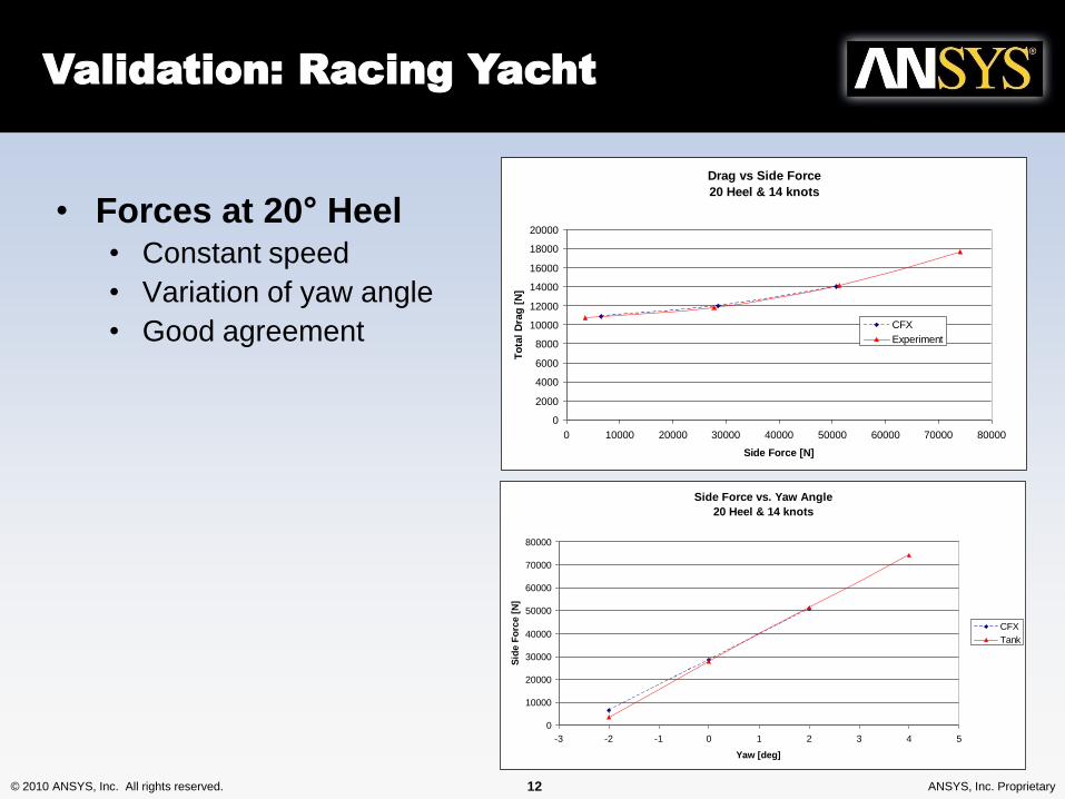
Drag vs Side Force
20 Heel & 14 knots
0
2000
4000
6000
8000
10000
12000
14000
16000
18000
20000
0 10000 20000 30000 40000 50000 60000 70000 80000
Side Force [N]
To
tal
Dra
g [
N]
CFX
Experiment
Validation: Racing Yacht
Side Force vs. Yaw Angle
20 Heel & 14 knots
0
10000
20000
30000
40000
50000
60000
70000
80000
-3 -2 -1 0 1 2 3 4 5
Yaw [deg]
Sid
e F
orc
e [
N]
CFX
Tank
• Forces at 20° Heel• Constant speed
• Variation of yaw angle
• Good agreement
© 2010 ANSYS, Inc. All rights reserved. 13 ANSYS, Inc. Proprietary
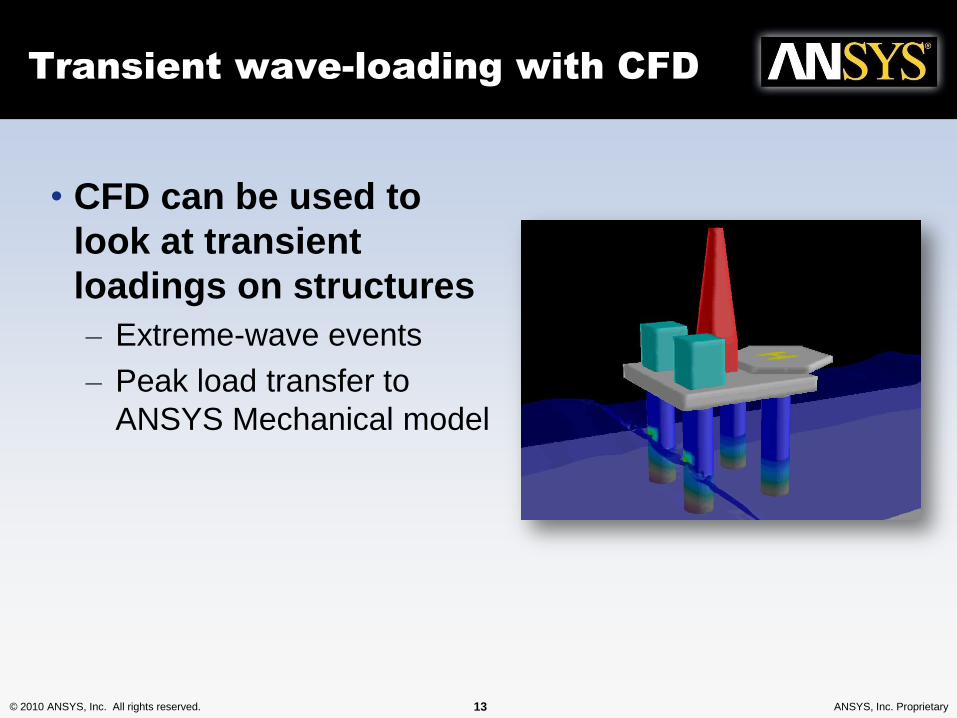
Transient wave-loading with CFD
• CFD can be used to
look at transient
loadings on structures
– Extreme-wave events
– Peak load transfer to
ANSYS Mechanical model

© 2010 ANSYS, Inc. All rights reserved. 14 ANSYS, Inc. Proprietary© 2010 ANSYS, Inc. All rights reserved. 14 ANSYS, Inc. Proprietary
Motion response
© 2010 ANSYS, Inc. All rights reserved. 15 ANSYS, Inc. Proprietary
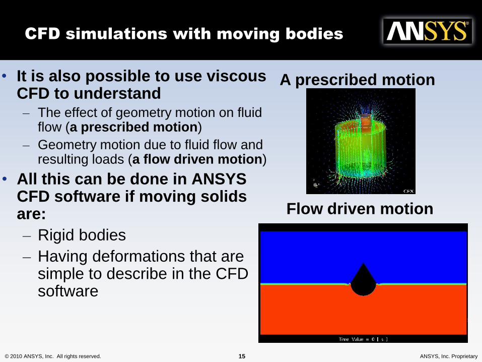
• It is also possible to use viscous CFD to understand– The effect of geometry motion on fluid
flow (a prescribed motion)
– Geometry motion due to fluid flow and resulting loads (a flow driven motion)
• All this can be done in ANSYS CFD software if moving solids are:
– Rigid bodies
– Having deformations that are simple to describe in the CFD software
CFD simulations with moving bodies
A prescribed motion
Flow driven motion
© 2010 ANSYS, Inc. All rights reserved. 16 ANSYS, Inc. Proprietary
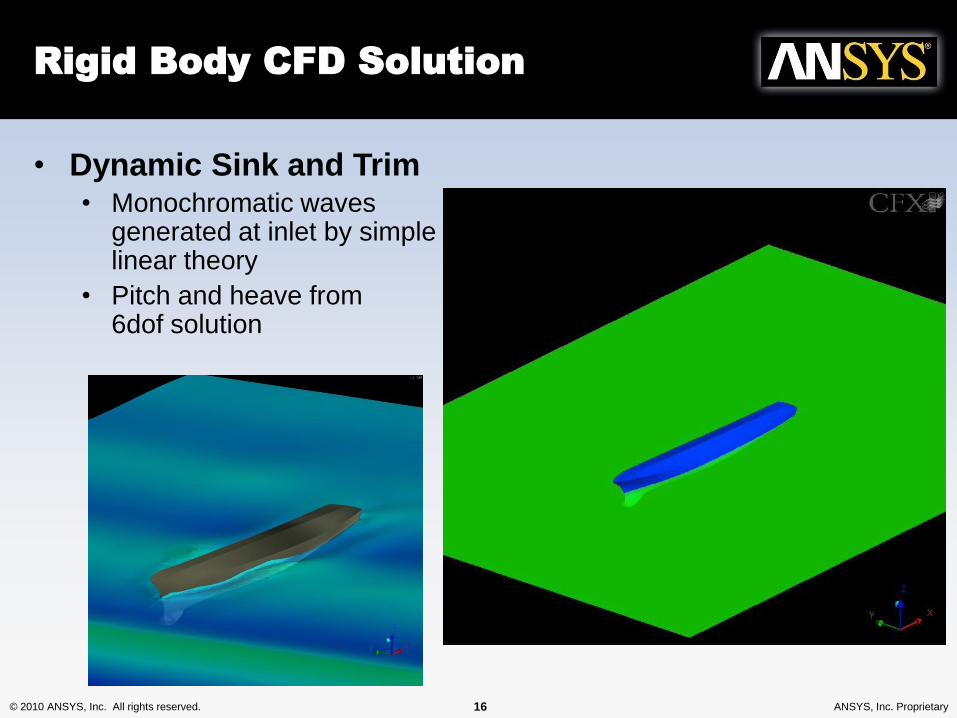
• Dynamic Sink and Trim• Monochromatic waves
generated at inlet by simplelinear theory
• Pitch and heave from6dof solution
Rigid Body CFD Solution

© 2010 ANSYS, Inc. All rights reserved. 24 ANSYS, Inc. Proprietary© 2010 ANSYS, Inc. All rights reserved. 24 ANSYS, Inc. Proprietary
Mooring example
© 2010 ANSYS, Inc. All rights reserved. 25 ANSYS, Inc. Proprietary
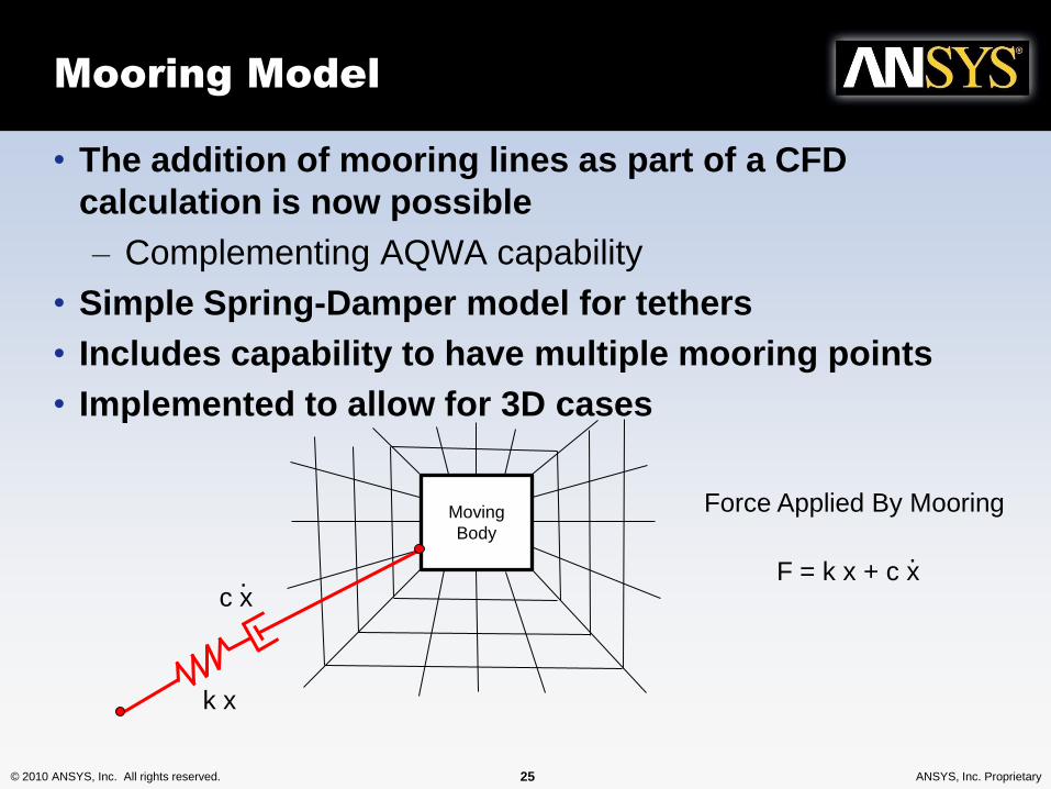
Mooring Model
• The addition of mooring lines as part of a CFD
calculation is now possible
– Complementing AQWA capability
• Simple Spring-Damper model for tethers
• Includes capability to have multiple mooring points
• Implemented to allow for 3D cases
k x
c x. F = k x + c x
.
Moving
Body
Force Applied By Mooring
© 2010 ANSYS, Inc. All rights reserved. 26 ANSYS, Inc. Proprietary
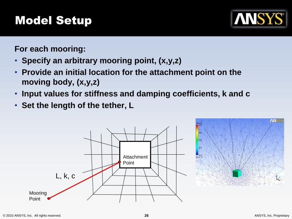
Model Setup
For each mooring:
• Specify an arbitrary mooring point, (x,y,z)
• Provide an initial location for the attachment point on the
moving body, (x,y,z)
• Input values for stiffness and damping coefficients, k and c
• Set the length of the tether, L
Mooring
Point
Attachment
Point
L, k, c
© 2010 ANSYS, Inc. All rights reserved. 27 ANSYS, Inc. Proprietary
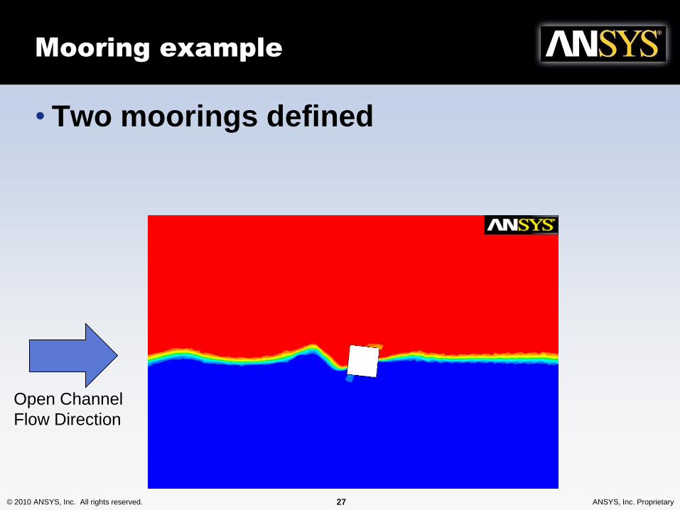
Mooring example
• Two moorings defined
Open Channel
Flow Direction
© 2010 ANSYS, Inc. All rights reserved. 28 ANSYS, Inc. Proprietary© 2010 ANSYS, Inc. All rights reserved. 28 ANSYS, Inc. Proprietary
Vortex Induced Vibration
© 2010 ANSYS, Inc. All rights reserved. 29 ANSYS, Inc. Proprietary
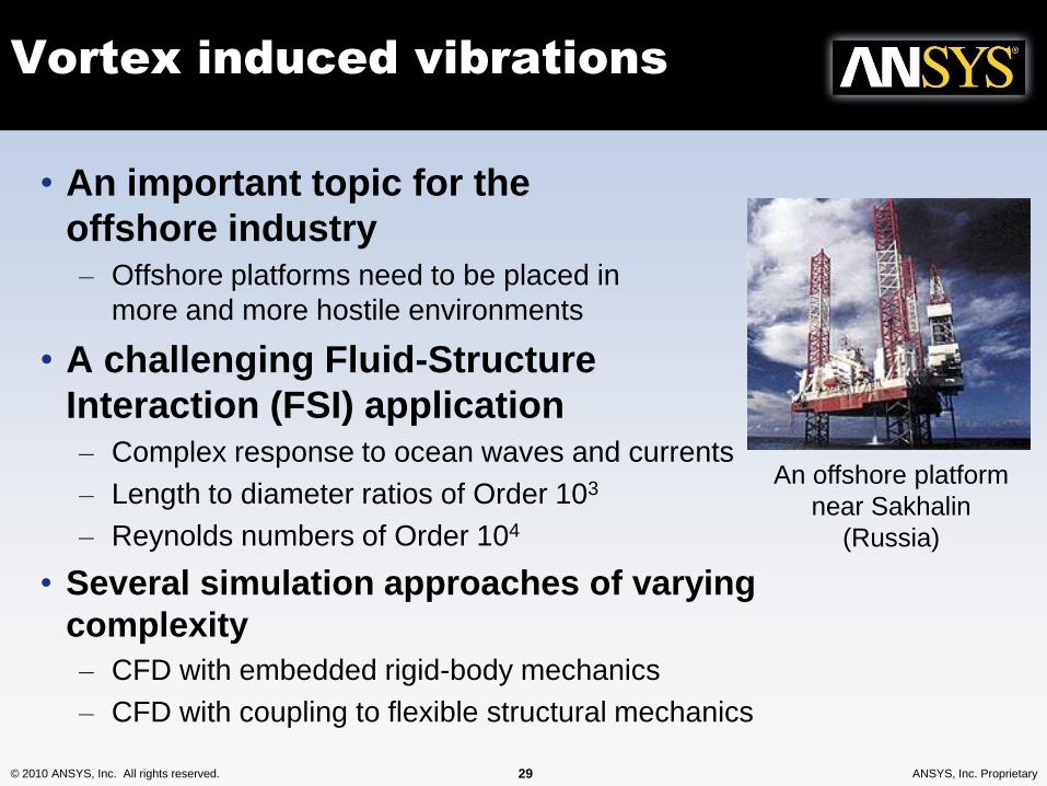
Vortex induced vibrations
• An important topic for the
offshore industry– Offshore platforms need to be placed in
more and more hostile environments
• A challenging Fluid-Structure
Interaction (FSI) application– Complex response to ocean waves and currents
– Length to diameter ratios of Order 103
– Reynolds numbers of Order 104
• Several simulation approaches of varying
complexity
– CFD with embedded rigid-body mechanics
– CFD with coupling to flexible structural mechanics
An offshore platform
near Sakhalin
(Russia)
© 2010 ANSYS, Inc. All rights reserved. 30 ANSYS, Inc. Proprietary
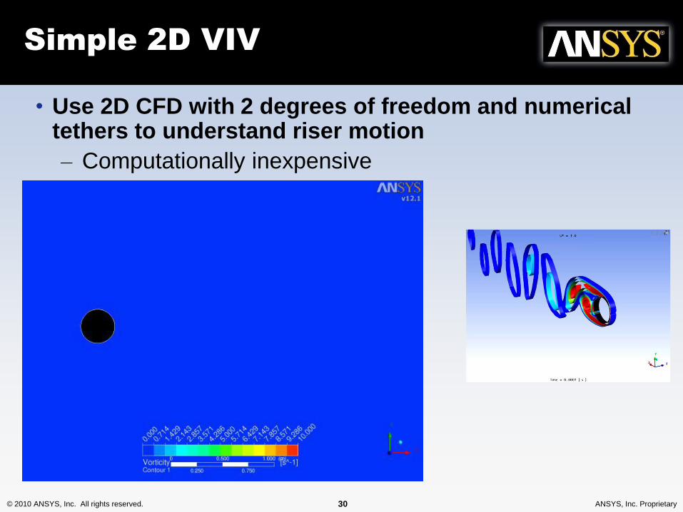
Simple 2D VIV
• Use 2D CFD with 2 degrees of freedom and numerical tethers to understand riser motion
– Computationally inexpensive
© 2010 ANSYS, Inc. All rights reserved. 31 ANSYS, Inc. Proprietary
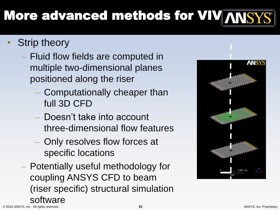
More advanced methods for VIV
• Strip theory
– Fluid flow fields are computed in
multiple two-dimensional planes
positioned along the riser
– Computationally cheaper than
full 3D CFD
– Doesn’t take into account
three-dimensional flow features
– Only resolves flow forces at
specific locations
– Potentially useful methodology for
coupling ANSYS CFD to beam
(riser specific) structural simulation
software
© 2010 ANSYS, Inc. All rights reserved. 32 ANSYS, Inc. Proprietary
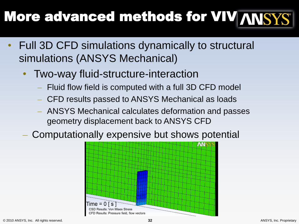
More advanced methods for VIV
• Full 3D CFD simulations dynamically to structural
simulations (ANSYS Mechanical)
• Two-way fluid-structure-interaction– Fluid flow field is computed with a full 3D CFD model
– CFD results passed to ANSYS Mechanical as loads
– ANSYS Mechanical calculates deformation and passes
geometry displacement back to ANSYS CFD
– Computationally expensive but shows potential
© 2010 ANSYS, Inc. All rights reserved. 33 ANSYS, Inc. Proprietary
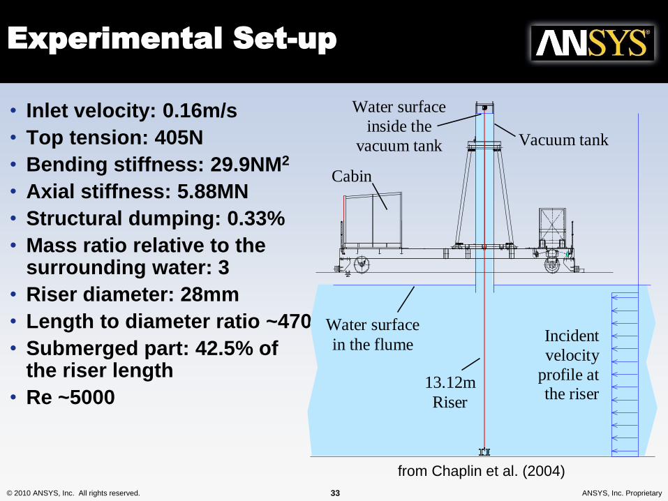
Experimental Set-up
• Inlet velocity: 0.16m/s
• Top tension: 405N
• Bending stiffness: 29.9NM2
• Axial stiffness: 5.88MN
• Structural dumping: 0.33%
• Mass ratio relative to the surrounding water: 3
• Riser diameter: 28mm
• Length to diameter ratio ~470
• Submerged part: 42.5% of the riser length
• Re ~5000
Water surface
inside the
vacuum tank
Water surface
in the flume
Vacuum tank
13.12m
Riser
Cabin
Incident
velocity
profile at the riser
1195
from Chaplin et al. (2004)
© 2010 ANSYS, Inc. All rights reserved. 34 ANSYS, Inc. Proprietary
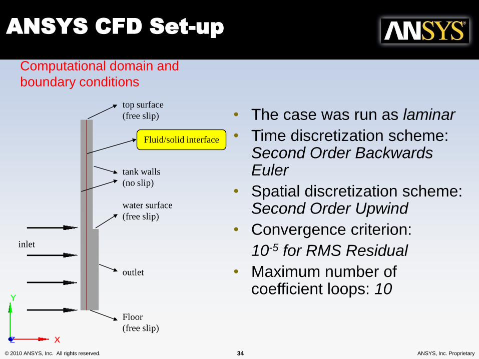
ANSYS CFD Set-up
top surface
(free slip)
tank walls
(no slip)
water surface
(free slip)
outlet
Floor
(free slip)
Computational domain and
boundary conditions
Fluid/solid interface
• The case was run as laminar
• Time discretization scheme: Second Order Backwards Euler
• Spatial discretization scheme: Second Order Upwind
• Convergence criterion:
10-5 for RMS Residual
• Maximum number of coefficient loops: 10
inlet
© 2010 ANSYS, Inc. All rights reserved. 35 ANSYS, Inc. Proprietary
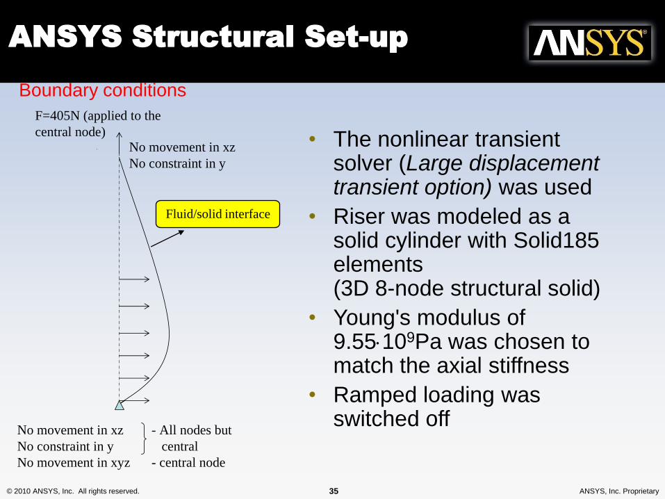
F=405N (applied to the
central node)No movement in xz
No constraint in y
No movement in xz
No constraint in y
No movement in xyz
- All nodes but
central
- central node
Boundary conditions
Fluid/solid interface
ANSYS Structural Set-up
• The nonlinear transient solver (Large displacement transient option) was used
• Riser was modeled as a solid cylinder with Solid185 elements (3D 8-node structural solid)
• Young's modulus of 9.55109Pa was chosen to match the axial stiffness
• Ramped loading was switched off
© 2010 ANSYS, Inc. All rights reserved. 36 ANSYS, Inc. Proprietary
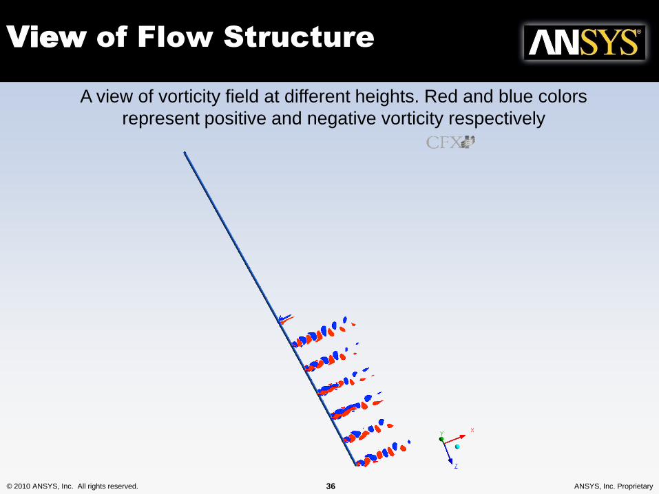
View of Flow Structure
A view of vorticity field at different heights. Red and blue colors
represent positive and negative vorticity respectively
© 2010 ANSYS, Inc. All rights reserved. 37 ANSYS, Inc. Proprietary
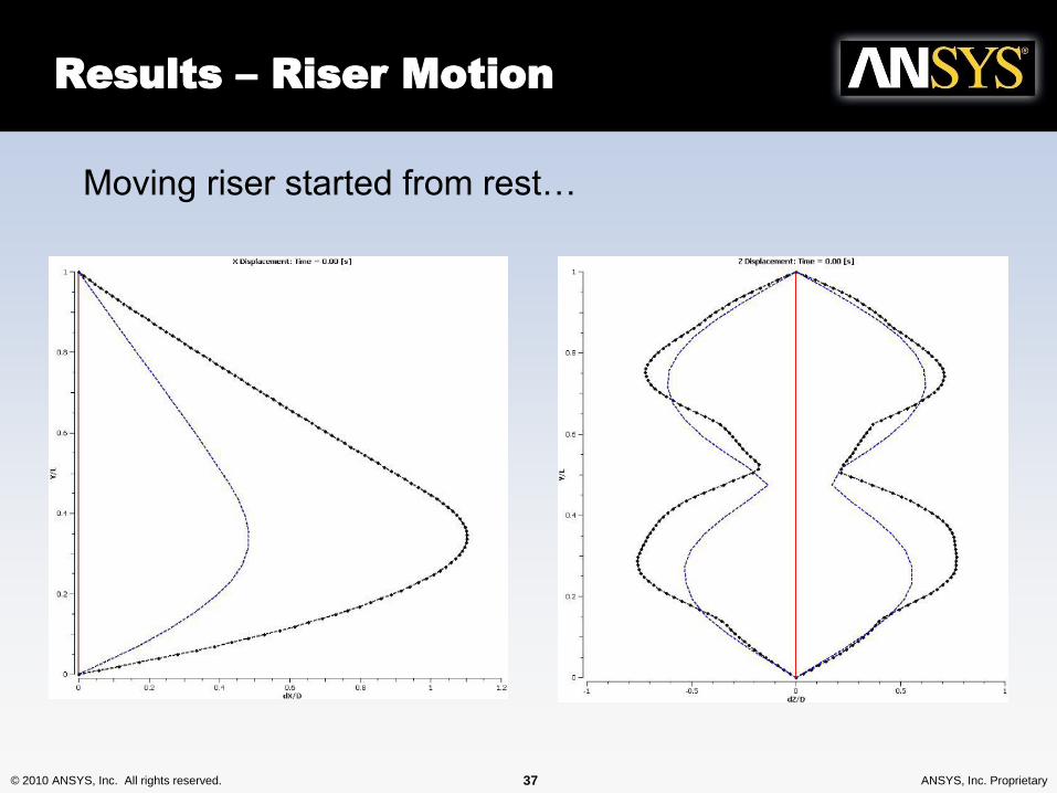
Results – Riser Motion
Moving riser started from rest…
© 2010 ANSYS, Inc. All rights reserved. 39 ANSYS, Inc. Proprietary© 2010 ANSYS, Inc. All rights reserved. 39 ANSYS, Inc. Proprietary
Added-Mass and
Damping Calculation
© 2010 ANSYS, Inc. All rights reserved. 40 ANSYS, Inc. Proprietary
Added-Mass and Damping
• When simulating floating bodies, or mooring systems,
some 3D-panel method codes and multi-body
dynamics codes require additional coefficients in
order to get an accurate response.
• The effect of these coefficients is implicitly included in
full CFD analyses
• Sometimes coefficients can be estimated for simple
geometries
• For complex geometry we can calculate them quickly
using CFD
© 2010 ANSYS, Inc. All rights reserved. 41 ANSYS, Inc. Proprietary
Added-Mass and Damping
• Perform transient forced sinusoidal motion simulation
– Eg. Heave, sway, and look at variation with amplitude
and frequency
• Examine reaction force response of the structure, and
the phase change (compared to displacement)
• Coefficients Obtained by Extracting Fourier
Coefficients of the Fundamental Frequency Over a
Time Period T
• Higher Order Components of Coefficients Could also
Have Been Extracted Using similar Techniques Based
on Fourier Analysis
© 2010 ANSYS, Inc. All rights reserved. 42 ANSYS, Inc. Proprietary
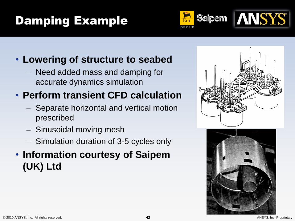
Damping Example
• Lowering of structure to seabed
– Need added mass and damping for
accurate dynamics simulation
• Perform transient CFD calculation
– Separate horizontal and vertical motion
prescribed
– Sinusoidal moving mesh
– Simulation duration of 3-5 cycles only
• Information courtesy of Saipem
(UK) Ltd
EniG R O U P
© 2010 ANSYS, Inc. All rights reserved. 43 ANSYS, Inc. Proprietary
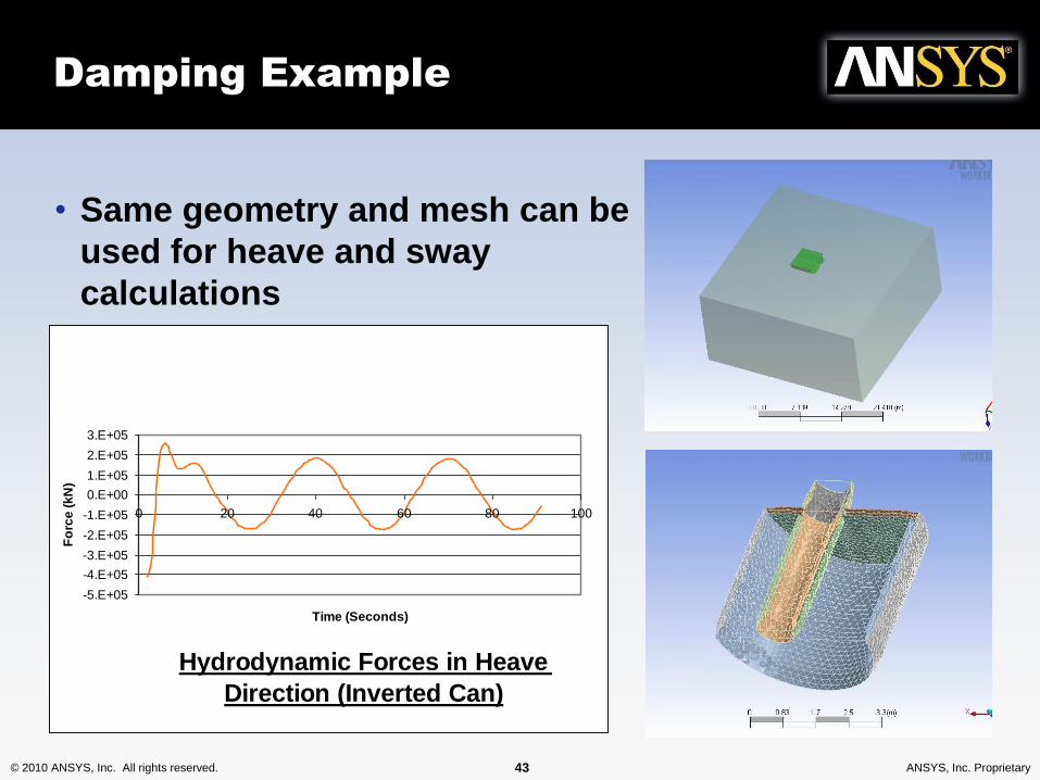
Damping Example
• Same geometry and mesh can be
used for heave and sway
calculations
Hydrodynamic Forces in Heave
Direction (Inverted Can)
-5.E+05
-4.E+05
-3.E+05
-2.E+05
-1.E+05
0.E+00
1.E+05
2.E+05
3.E+05
0 20 40 60 80 100
Time (Seconds)
Fo
rce
(k
N)
© 2010 ANSYS, Inc. All rights reserved. 44 ANSYS, Inc. Proprietary
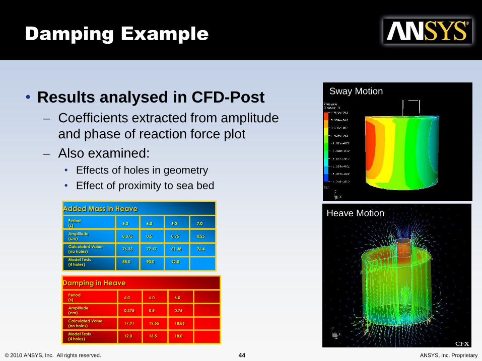
Damping Example
• Results analysed in CFD-Post
– Coefficients extracted from amplitude
and phase of reaction force plot
– Also examined:
• Effects of holes in geometry
• Effect of proximity to sea bed
Sway Motion
Heave MotionPeriod
(s)
Amplitude
(cm)
Calculated Value
(no holes)
Model Tests
(4 holes)
Added Mass in Heave
6.0
0.375
76.33
88.0
6.0
0.5
77.17
90.0
6.0
0.75
81.38
92.0
7.0
0.25
76.4
-
Period
(s)
Amplitude
(cm)
Calculated Value
(no holes)
Model Tests
(4 holes)
6.0
0.375
17.91
12.0
6.0
0.5
19.55
13.5
6.0
0.75
18.86
18.0
Damping in Heave
© 2010 ANSYS, Inc. All rights reserved. 47 ANSYS, Inc. Proprietary
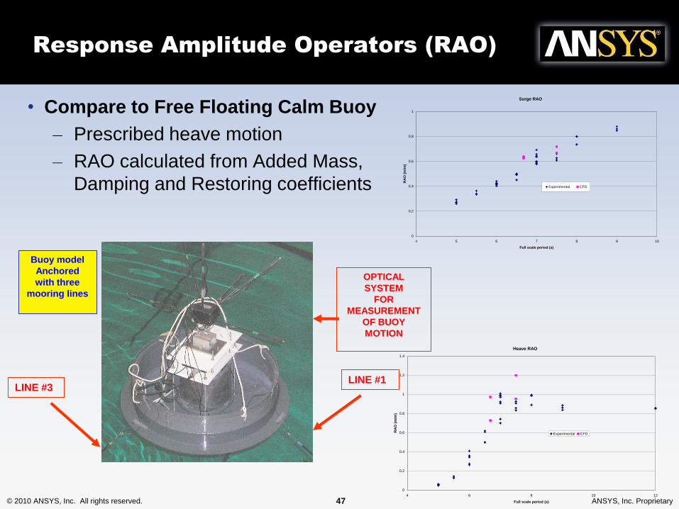
Response Amplitude Operators (RAO)
• Compare to Free Floating Calm Buoy
– Prescribed heave motion
– RAO calculated from Added Mass,
Damping and Restoring coefficients
Surge RAO
0
0.2
0.4
0.6
0.8
1
4 5 6 7 8 9 10
Full scale period (s)
RA
O (
m/m
)
Experimental CFD
Heave RAO
0
0.2
0.4
0.6
0.8
1
1.2
1.4
4 6 8 10 12
Full scale period (s)
RA
O (
m/m
)
Experimental CFD
Buoy model
Anchored
with three
mooring lines
LINE #1LINE #3
OPTICAL
SYSTEM
FOR
MEASUREMENT
OF BUOY
MOTION
© 2010 ANSYS, Inc. All rights reserved. 49 ANSYS, Inc. Proprietary© 2010 ANSYS, Inc. All rights reserved. 49 ANSYS, Inc. Proprietary
Transient two-way
fluid-structure-
interaction
© 2010 ANSYS, Inc. All rights reserved. 50 ANSYS, Inc. Proprietary
Transient Dynamics: Two-way FSI
• 2-Way Coupled Fluid Structure Interaction
– Structural FEA code used to solve for vessel displacement
– Loads exchanged in both directions• Between CFD and FEA code
– More ‘coupled’ solution than 1-way• Introduce concept of ‘coupling convergence’
– Transient or steady-state• Single exchange per timestep – explicit
• Multiple exchange per timestep – implicit
– Important for strongly coupled problems
© 2010 ANSYS, Inc. All rights reserved. 51 ANSYS, Inc. Proprietary
Transient Dynamics: Two-way FSI
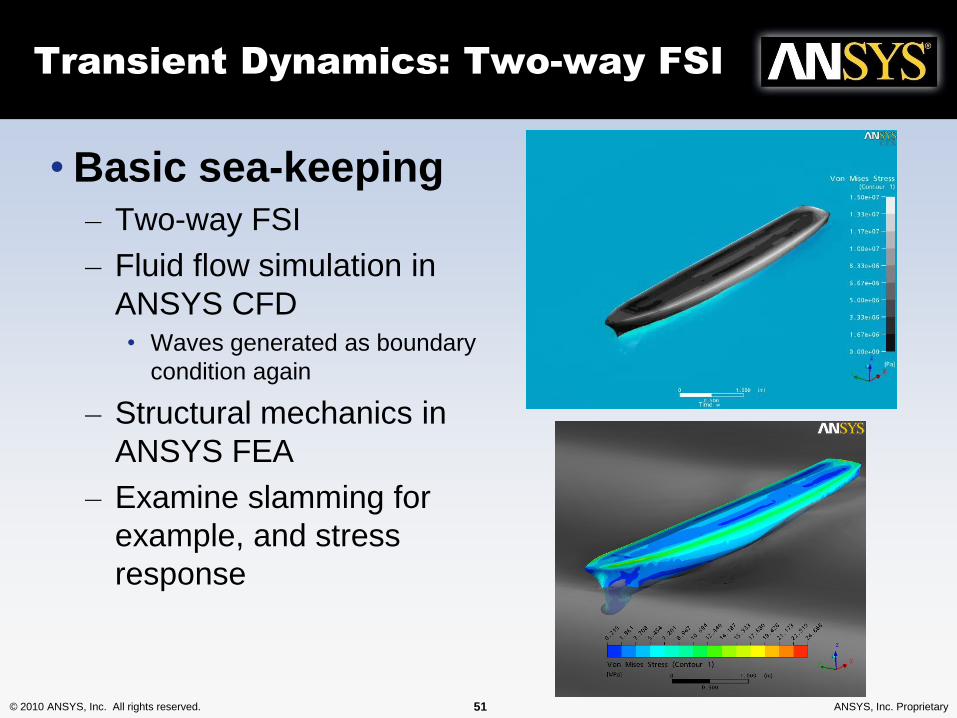
• Basic sea-keeping– Two-way FSI
– Fluid flow simulation in
ANSYS CFD• Waves generated as boundary
condition again
– Structural mechanics in
ANSYS FEA
– Examine slamming for
example, and stress
response
© 2010 ANSYS, Inc. All rights reserved. 52 ANSYS, Inc. Proprietary
Guest presentation
• BMT Fluid Mechanics– Hydrodynamic loading on a subsea
pipeline
– Ballast tank sloshing in hurricanes
– Submarine hydrodynamics
– …
© 2010 ANSYS, Inc. All rights reserved. 53 ANSYS, Inc. Proprietary© 2010 ANSYS, Inc. All rights reserved. 53 ANSYS, Inc. Proprietary
Oscillating Water Column
Simulation
© 2010 ANSYS, Inc. All rights reserved. 54 ANSYS, Inc. Proprietary
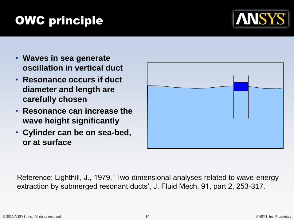
OWC principle
• Waves in sea generate
oscillation in vertical duct
• Resonance occurs if duct
diameter and length are
carefully chosen
• Resonance can increase the
wave height significantly
• Cylinder can be on sea-bed,
or at surface
Reference: Lighthill, J., 1979, ‘Two-dimensional analyses related to wave-energy
extraction by submerged resonant ducts’, J. Fluid Mech, 91, part 2, 253-317.
© 2010 ANSYS, Inc. All rights reserved. 55 ANSYS, Inc. Proprietary
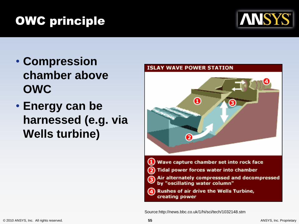
OWC principle
• Compression
chamber above
OWC
• Energy can be
harnessed (e.g. via
Wells turbine)
Source:http://news.bbc.co.uk/1/hi/sci/tech/1032148.stm
© 2010 ANSYS, Inc. All rights reserved. 57 ANSYS, Inc. Proprietary
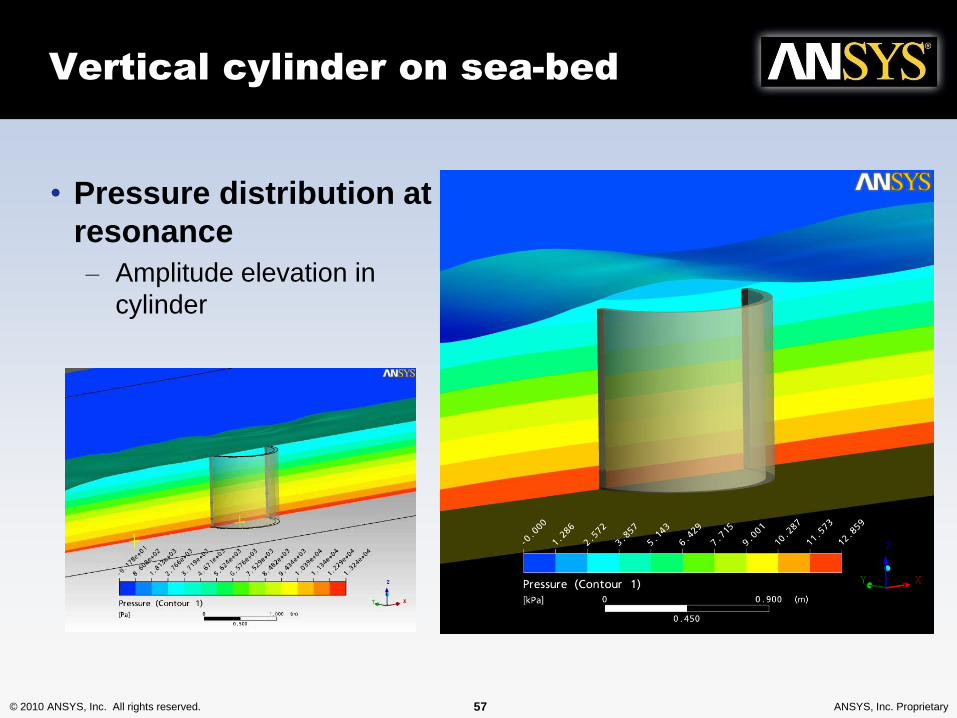
Vertical cylinder on sea-bed
• Pressure distribution at
resonance
– Amplitude elevation in
cylinder
© 2010 ANSYS, Inc. All rights reserved. 58 ANSYS, Inc. Proprietary
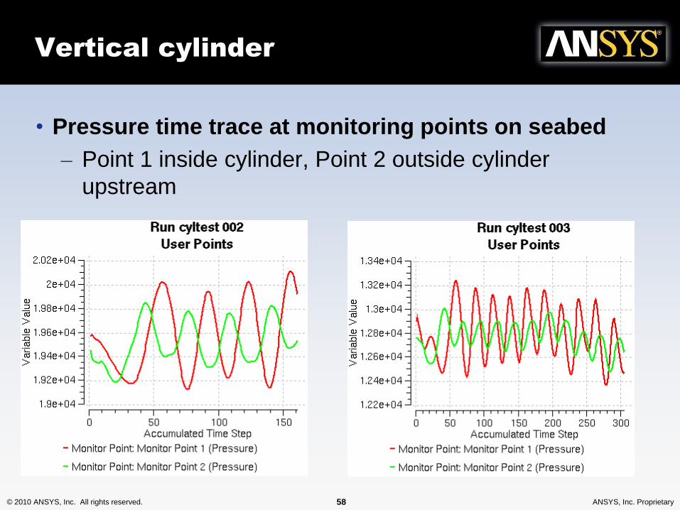
Vertical cylinder
• Pressure time trace at monitoring points on seabed
– Point 1 inside cylinder, Point 2 outside cylinder
upstream
© 2010 ANSYS, Inc. All rights reserved. 59 ANSYS, Inc. Proprietary
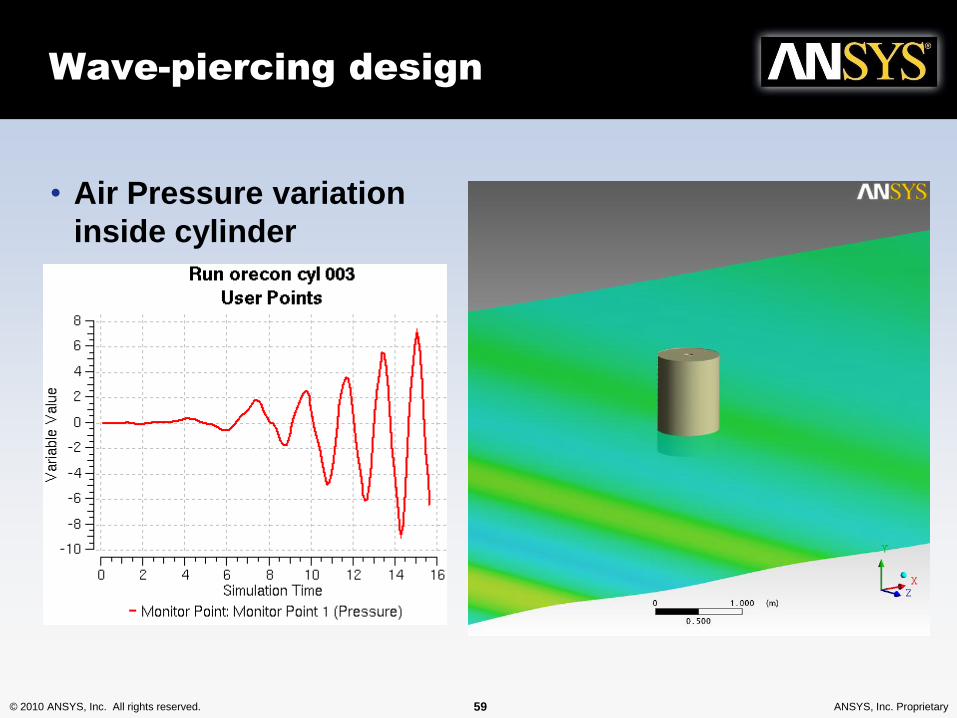
Wave-piercing design
• Air Pressure variation
inside cylinder
© 2010 ANSYS, Inc. All rights reserved. 60 ANSYS, Inc. Proprietary
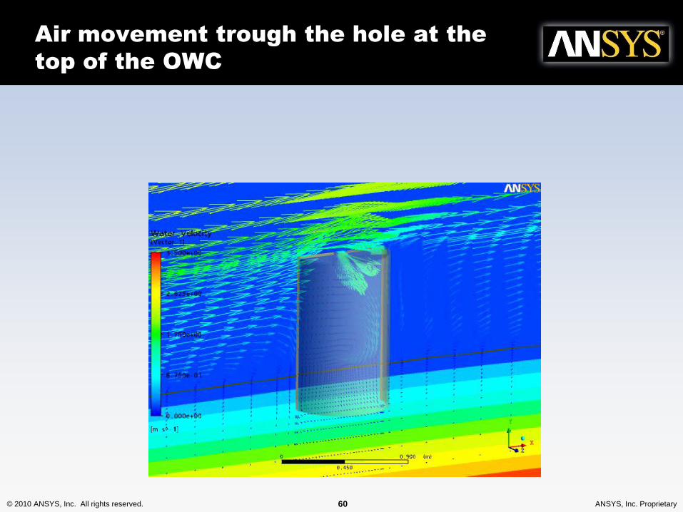
Air movement trough the hole at the
top of the OWC
© 2010 ANSYS, Inc. All rights reserved. 61 ANSYS, Inc. Proprietary© 2010 ANSYS, Inc. All rights reserved. 61 ANSYS, Inc. Proprietary
Tidal turbine
simulation using CFD
and one-way FSI
© 2010 ANSYS, Inc. All rights reserved. 62 ANSYS, Inc. Proprietary
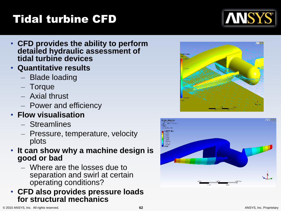
Tidal turbine CFD
• CFD provides the ability to perform detailed hydraulic assessment of tidal turbine devices
• Quantitative results
– Blade loading
– Torque
– Axial thrust
– Power and efficiency
• Flow visualisation
– Streamlines
– Pressure, temperature, velocity plots
• It can show why a machine design is good or bad
– Where are the losses due to separation and swirl at certain operating conditions?
• CFD also provides pressure loads for structural mechanics
© 2010 ANSYS, Inc. All rights reserved. 63 ANSYS, Inc. Proprietary
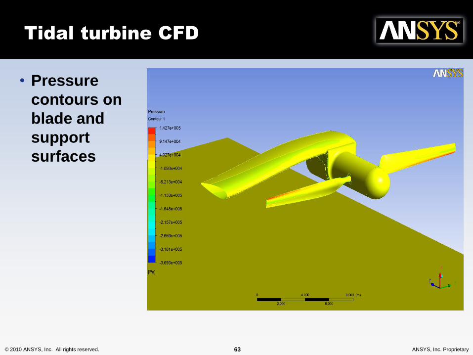
Tidal turbine CFD
• Pressure
contours on
blade and
support
surfaces
© 2010 ANSYS, Inc. All rights reserved. 64 ANSYS, Inc. Proprietary
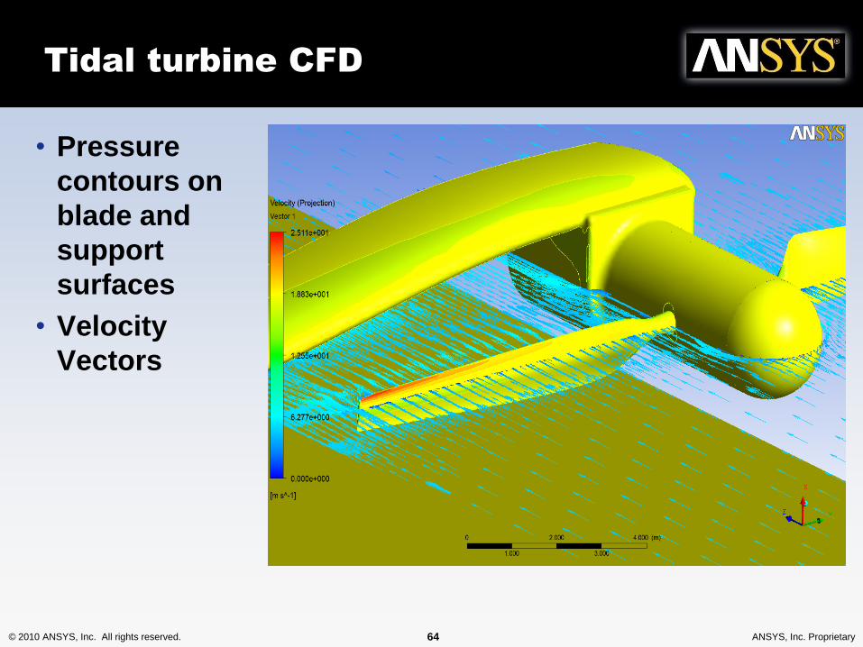
Tidal turbine CFD
• Pressure
contours on
blade and
support
surfaces
• Velocity
Vectors
© 2010 ANSYS, Inc. All rights reserved. 65 ANSYS, Inc. Proprietary
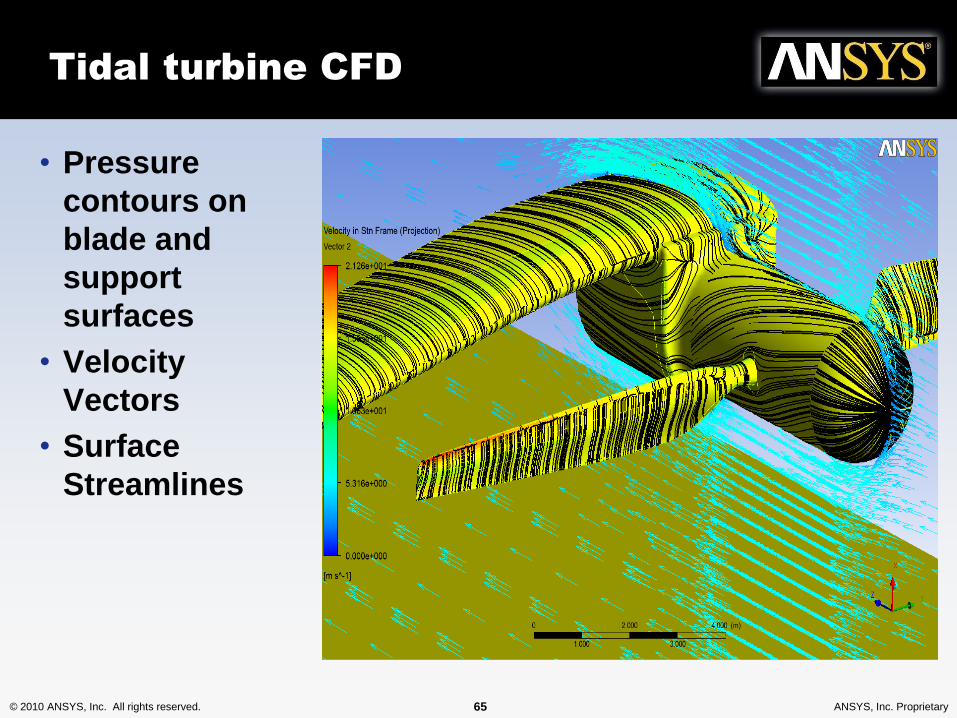
Tidal turbine CFD
• Pressure
contours on
blade and
support
surfaces
• Velocity
Vectors
• Surface
Streamlines
© 2010 ANSYS, Inc. All rights reserved. 66 ANSYS, Inc. Proprietary
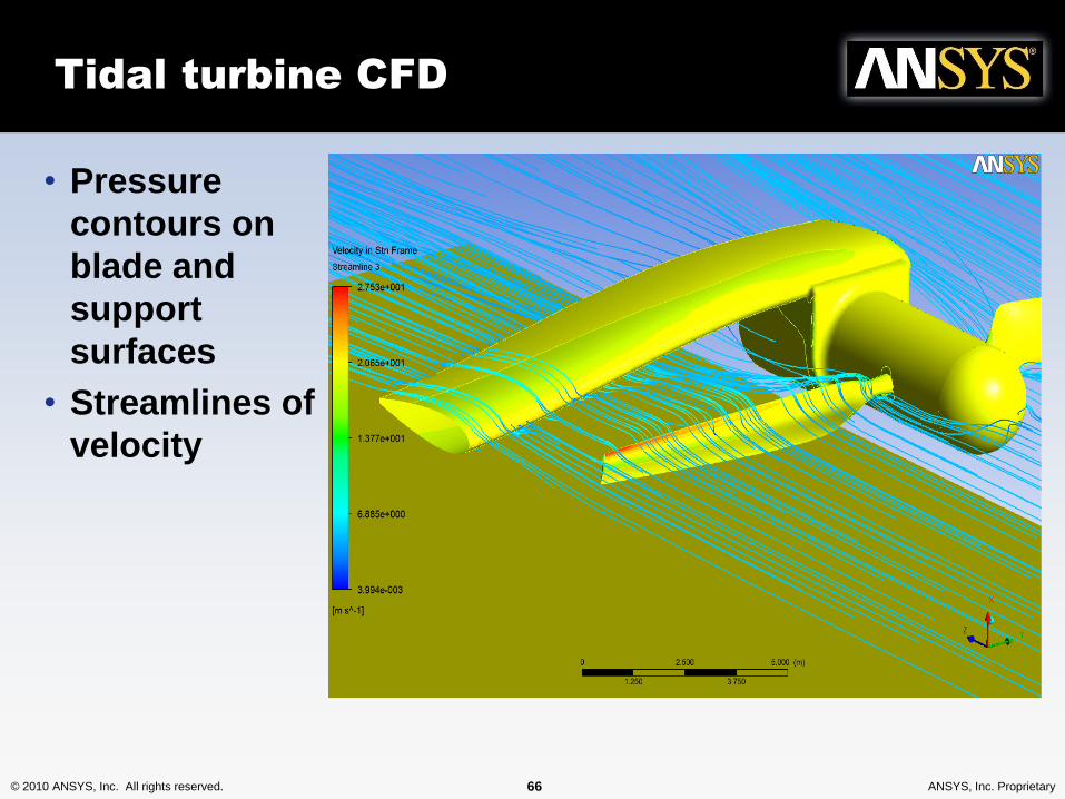
Tidal turbine CFD
• Pressure
contours on
blade and
support
surfaces
• Streamlines of
velocity
© 2010 ANSYS, Inc. All rights reserved. 67 ANSYS, Inc. Proprietary
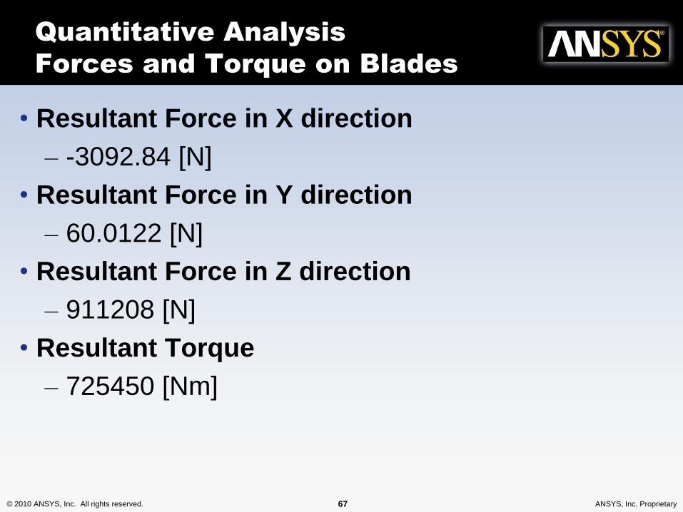
Quantitative Analysis
Forces and Torque on Blades
• Resultant Force in X direction
– -3092.84 [N]
• Resultant Force in Y direction
– 60.0122 [N]
• Resultant Force in Z direction
– 911208 [N]
• Resultant Torque
– 725450 [Nm]
© 2010 ANSYS, Inc. All rights reserved. 68 ANSYS, Inc. Proprietary
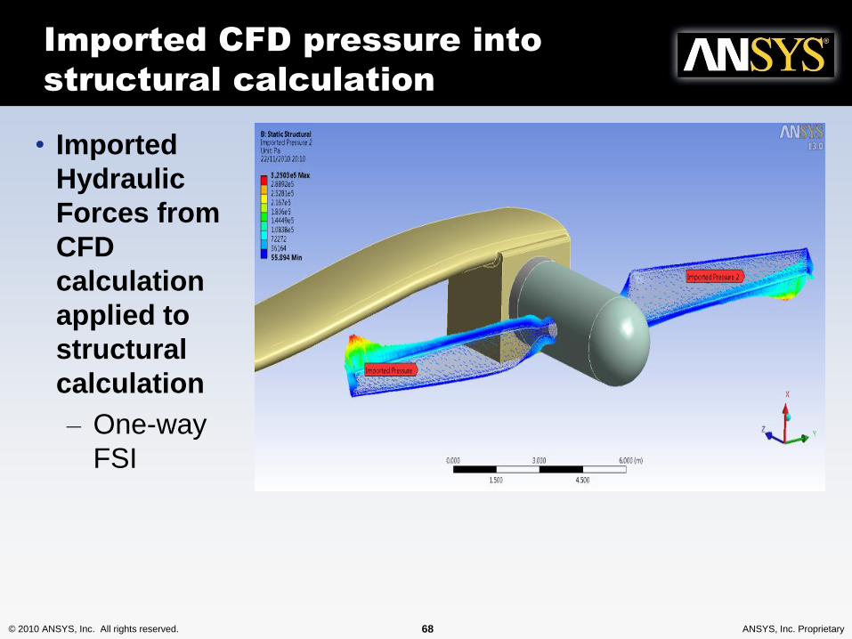
Imported CFD pressure into
structural calculation
• Imported
Hydraulic
Forces from
CFD
calculation
applied to
structural
calculation
– One-way
FSI
© 2010 ANSYS, Inc. All rights reserved. 69 ANSYS, Inc. Proprietary
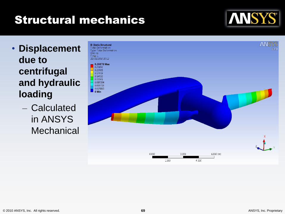
Structural mechanics
• Displacement
due to
centrifugal
and hydraulic
loading
– Calculated
in ANSYS
Mechanical
© 2010 ANSYS, Inc. All rights reserved. 70 ANSYS, Inc. Proprietary
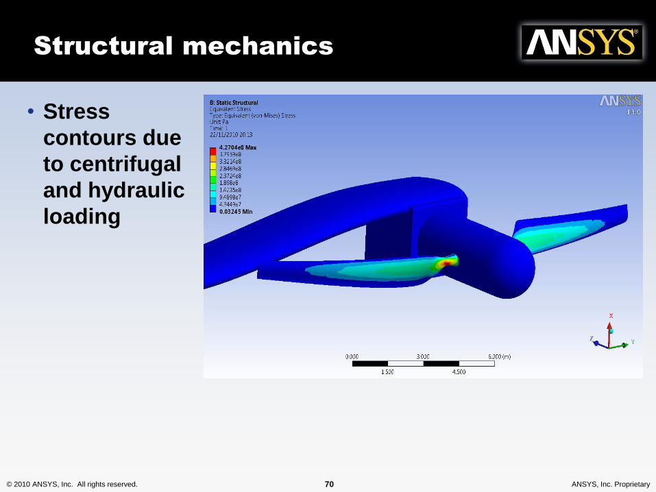
Structural mechanics
• Stress
contours due
to centrifugal
and hydraulic
loading
© 2010 ANSYS, Inc. All rights reserved. 71 ANSYS, Inc. Proprietary
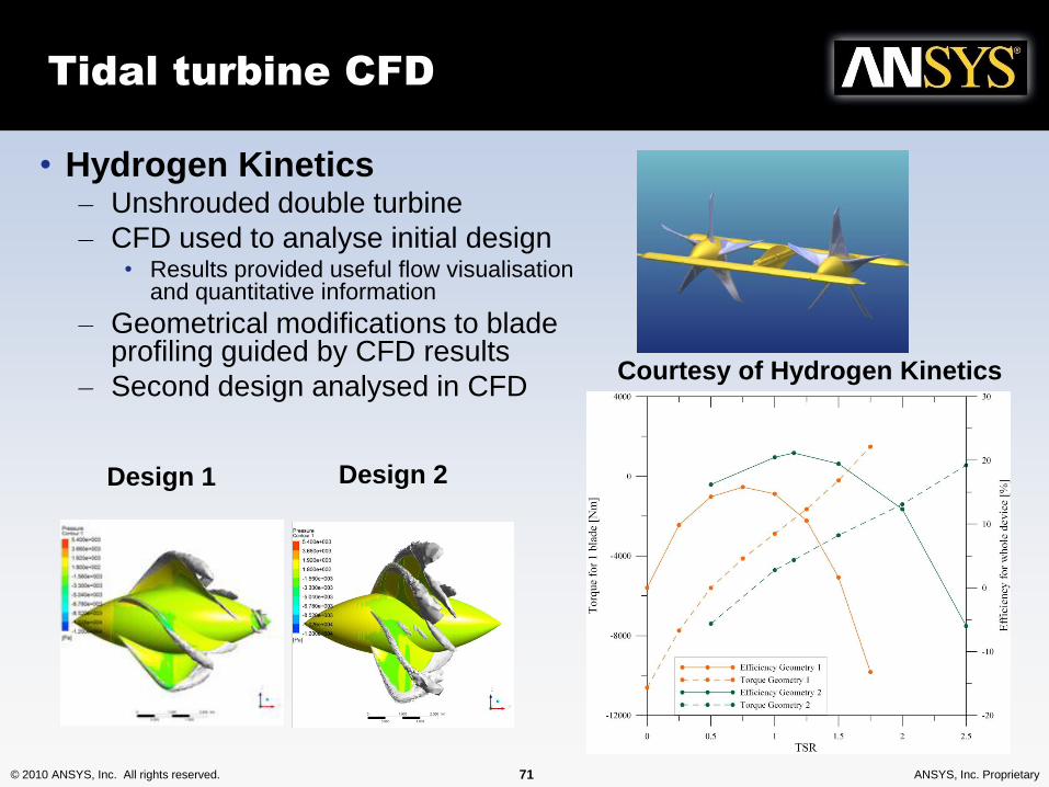
Tidal turbine CFD
• Hydrogen Kinetics– Unshrouded double turbine
– CFD used to analyse initial design• Results provided useful flow visualisation
and quantitative information
– Geometrical modifications to blade profiling guided by CFD results
– Second design analysed in CFDCourtesy of Hydrogen Kinetics
Design 1 Design 2
© 2010 ANSYS, Inc. All rights reserved. 72 ANSYS, Inc. Proprietary
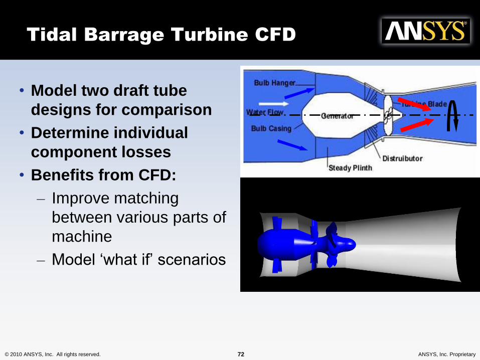
• Model two draft tube
designs for comparison
• Determine individual
component losses
• Benefits from CFD:
– Improve matching
between various parts of
machine
– Model ‘what if’ scenarios
Tidal Barrage Turbine CFD
© 2010 ANSYS, Inc. All rights reserved. 74 ANSYS, Inc. Proprietary
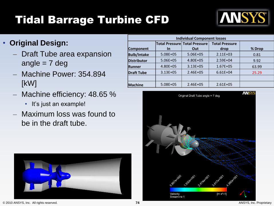
Tidal Barrage Turbine CFD
• Original Design:
– Draft Tube area expansion
angle = 7 deg
– Machine Power: 354.894
[kW]
– Machine efficiency: 48.65 %
• It’s just an example!
– Maximum loss was found to
be in the draft tube.
Individual Component losses
ComponentTotal Pressure
InTotal Pressure
OutTotal Pressure
drop % Drop
Bulb/Intake 5.08E+05 5.06E+05 2.11E+03 0.81
Distributor 5.06E+05 4.80E+05 2.59E+04 9.92
Runner 4.80E+05 3.13E+05 1.67E+05 63.99
Draft Tube 3.13E+05 2.46E+05 6.61E+04 25.29
Machine 5.08E+05 2.46E+05 2.61E+05
© 2010 ANSYS, Inc. All rights reserved. 75 ANSYS, Inc. Proprietary
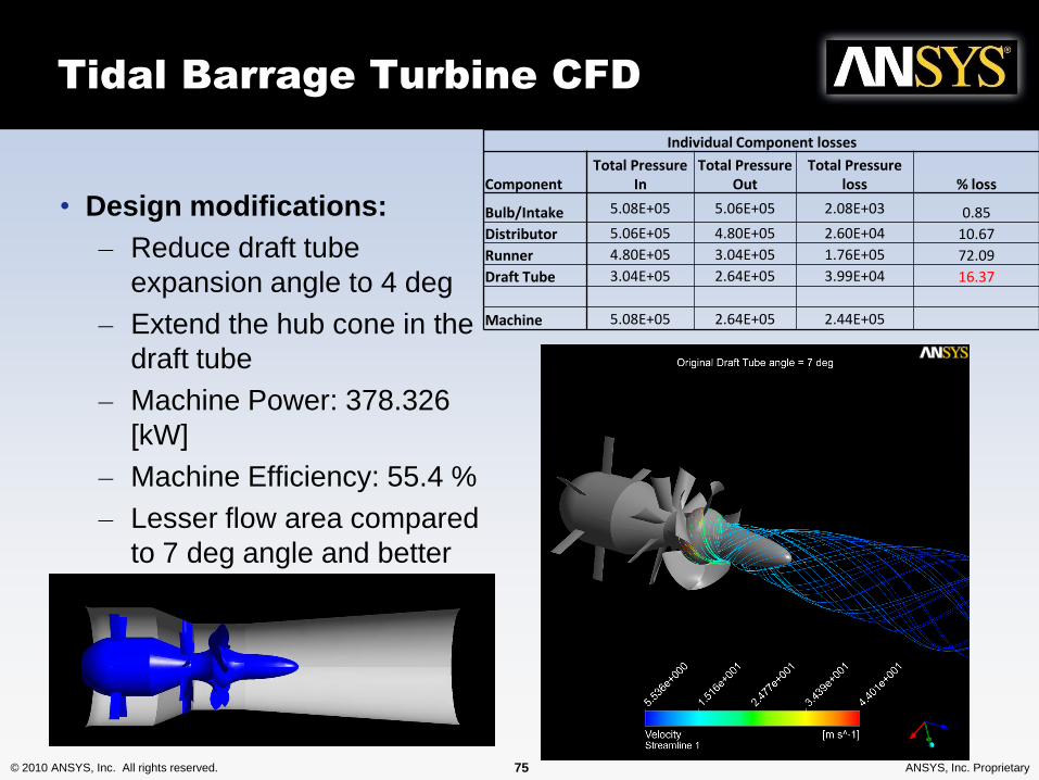
Tidal Barrage Turbine CFD
• Design modifications:
– Reduce draft tube
expansion angle to 4 deg
– Extend the hub cone in the
draft tube
– Machine Power: 378.326
[kW]
– Machine Efficiency: 55.4 %
– Lesser flow area compared
to 7 deg angle and better
attached flow on the longer
cone
Individual Component losses
ComponentTotal Pressure
InTotal Pressure
OutTotal Pressure
loss % loss
Bulb/Intake 5.08E+05 5.06E+05 2.08E+03 0.85
Distributor 5.06E+05 4.80E+05 2.60E+04 10.67
Runner 4.80E+05 3.04E+05 1.76E+05 72.09
Draft Tube 3.04E+05 2.64E+05 3.99E+04 16.37
Machine 5.08E+05 2.64E+05 2.44E+05
© 2010 ANSYS, Inc. All rights reserved. 76 ANSYS, Inc. Proprietary
Guest presentation
• Cardiff University– Tidal Stream Energy
© 2010 ANSYS, Inc. All rights reserved. 77 ANSYS, Inc. Proprietary© 2010 ANSYS, Inc. All rights reserved. 77 ANSYS, Inc. Proprietary
Tidal turbine farm
layouts
Ian Jones
© 2010 ANSYS, Inc. All rights reserved. 78 ANSYS, Inc. Proprietary
Site Specific Issues
• Trickle down – wind -> tidal
• WindModeller, vertical application based on ANSYS CFD
– Currently being extended to tidal flows
• Effect of geometry;
– Orography / Bathymetry
• Flow physics;
– Atmospheric
– Marine, free surface....
– Turbulence
– Inflow / ambient conditions
• Turbine interactions and the environment
– Resolved Turbines / Actuator Disk models
– Wakes, towers
© 2010 ANSYS, Inc. All rights reserved. 79 ANSYS, Inc. Proprietary
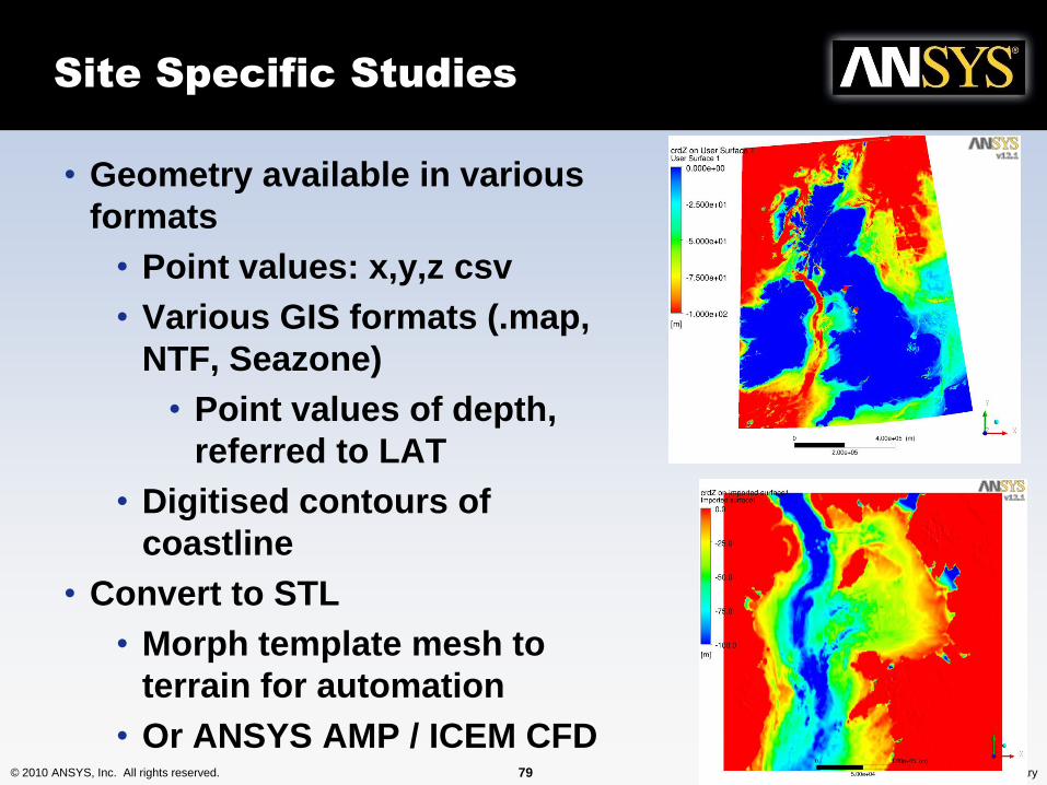
Site Specific Studies
• Geometry available in various
formats
• Point values: x,y,z csv
• Various GIS formats (.map,
NTF, Seazone)
• Point values of depth,
referred to LAT
• Digitised contours of
coastline
• Convert to STL
• Morph template mesh to
terrain for automation
• Or ANSYS AMP / ICEM CFD
© 2010 ANSYS, Inc. All rights reserved. 80 ANSYS, Inc. Proprietary
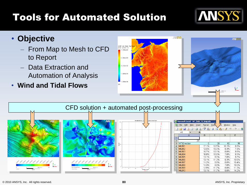
Tools for Automated Solution
• Objective
– From Map to Mesh to CFD
to Report
– Data Extraction and
Automation of Analysis
• Wind and Tidal Flows
CFD solution + automated post-processing
© 2010 ANSYS, Inc. All rights reserved. 81 ANSYS, Inc. Proprietary
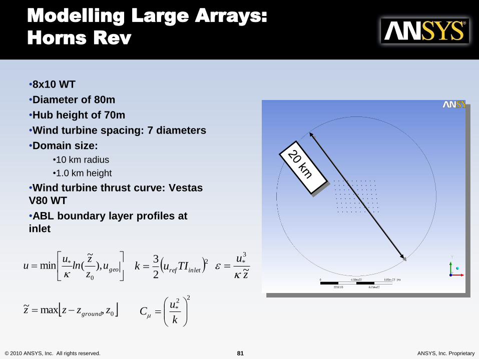
Modelling Large Arrays:
Horns Rev
•8x10 WT
•Diameter of 80m
•Hub height of 70m
•Wind turbine spacing: 7 diameters
•Domain size:
•10 km radius
•1.0 km height
•Wind turbine thrust curve: Vestas
V80 WT
•ABL boundary layer profiles at
inlet
geou
z
zln
uu ),
~(min
0
*
z
u~
3
*
0,max~ zzzz ground
22
3inletrefTIuk
22
*
k
uC
© 2010 ANSYS, Inc. All rights reserved. 82 ANSYS, Inc. Proprietary
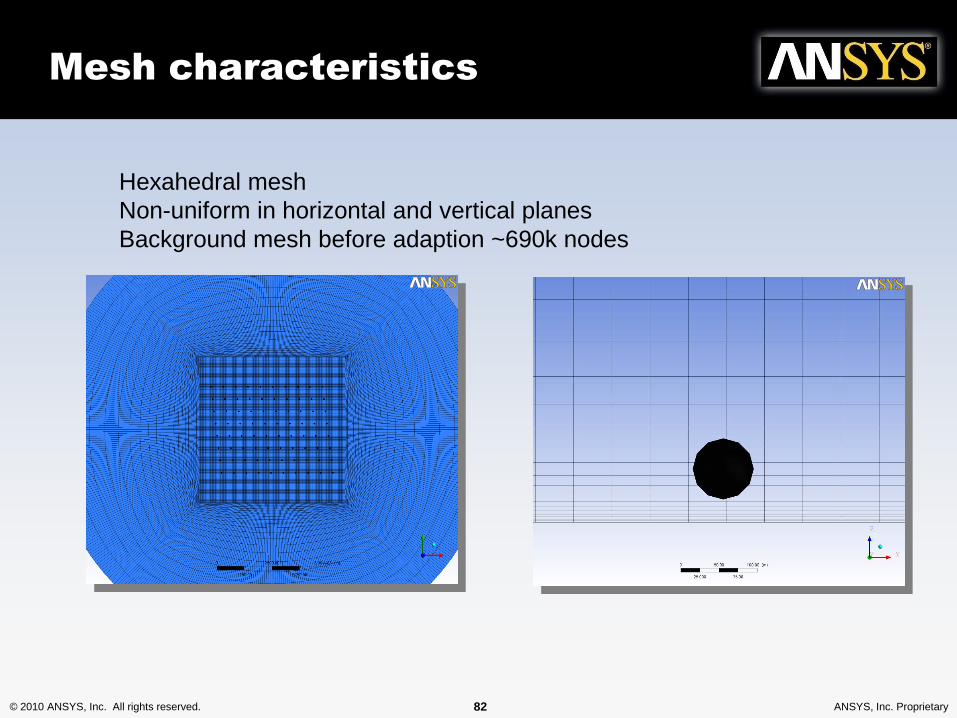
Mesh characteristics
Hexahedral mesh
Non-uniform in horizontal and vertical planes
Background mesh before adaption ~690k nodes
© 2010 ANSYS, Inc. All rights reserved. 83 ANSYS, Inc. Proprietary
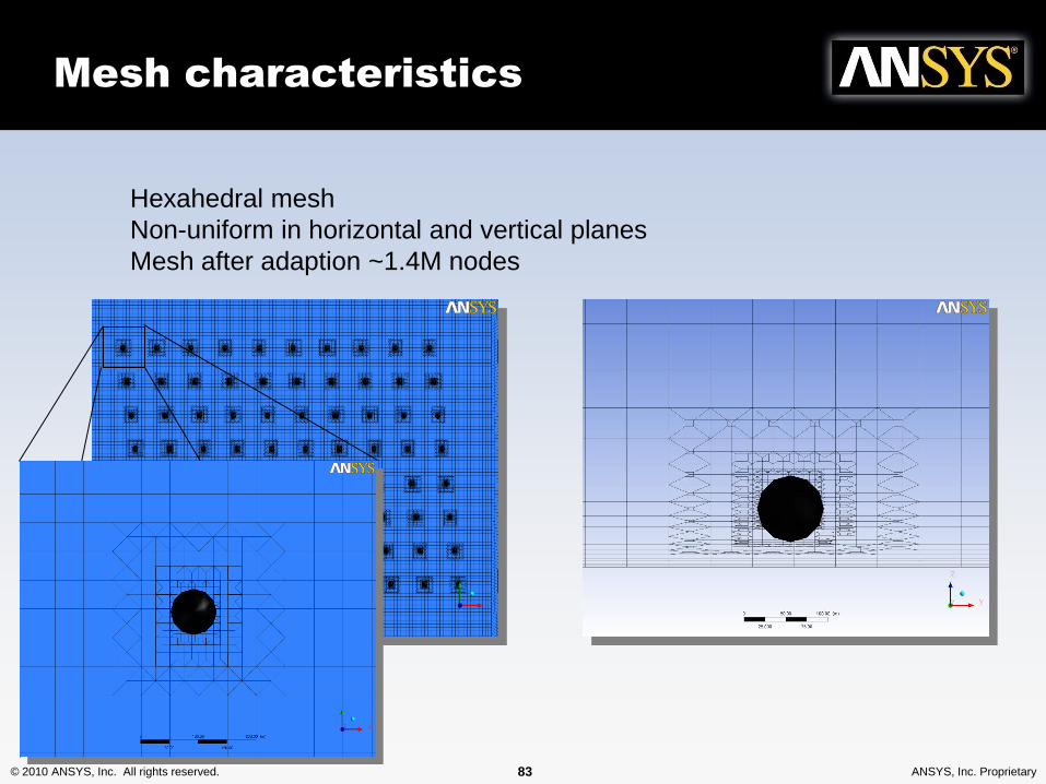
Mesh characteristics
Hexahedral mesh
Non-uniform in horizontal and vertical planes
Mesh after adaption ~1.4M nodes
© 2010 ANSYS, Inc. All rights reserved. 84 ANSYS, Inc. Proprietary
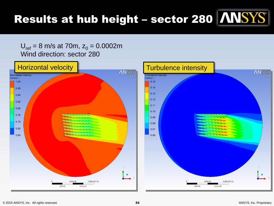
Results at hub height – sector 280
Horizontal velocity Turbulence intensity
Uref = 8 m/s at 70m, z0 = 0.0002m
Wind direction: sector 280
© 2010 ANSYS, Inc. All rights reserved. 85 ANSYS, Inc. Proprietary
Array Efficiency Sector 270-285,
Compared with Measurements
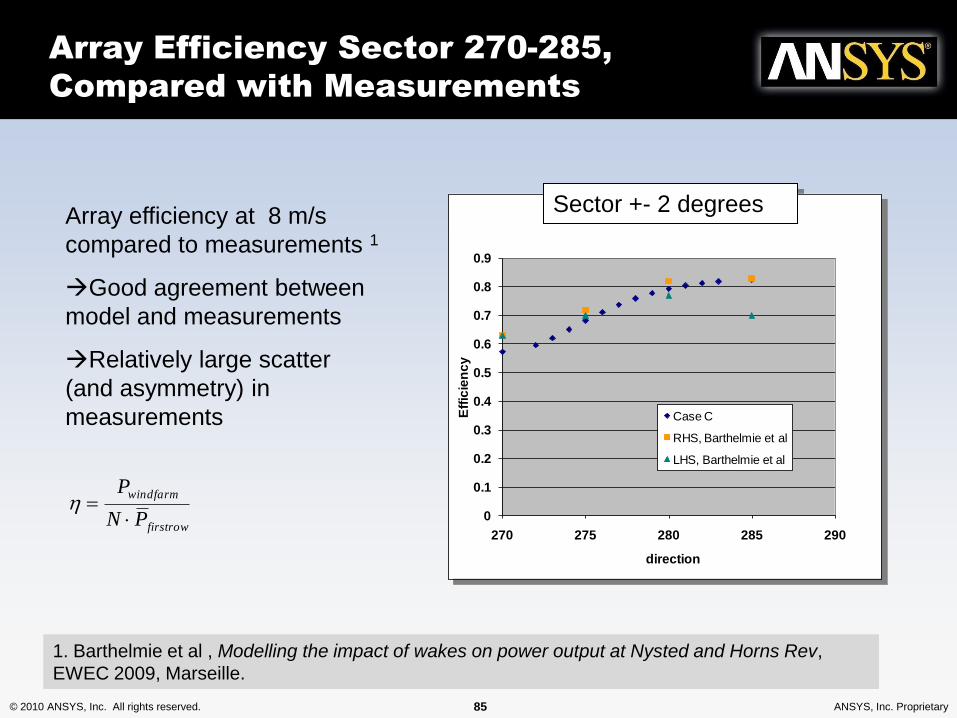
Array efficiency at 8 m/s
compared to measurements 1
Good agreement between
model and measurements
Relatively large scatter
(and asymmetry) in
measurements
0
0.1
0.2
0.3
0.4
0.5
0.6
0.7
0.8
0.9
270 275 280 285 290
Eff
icie
nc
y
direction
Array efficiency, sector +- 2 degrees
Case C
RHS, Barthelmie et al
LHS, Barthelmie et al
Sector +- 2 degrees
firstrow
windfarm
PN
P
1. Barthelmie et al , Modelling the impact of wakes on power output at Nysted and Horns Rev,
EWEC 2009, Marseille.
© 2010 ANSYS, Inc. All rights reserved. 86 ANSYS, Inc. Proprietary
East River: Verdant Generation 5
KHPS
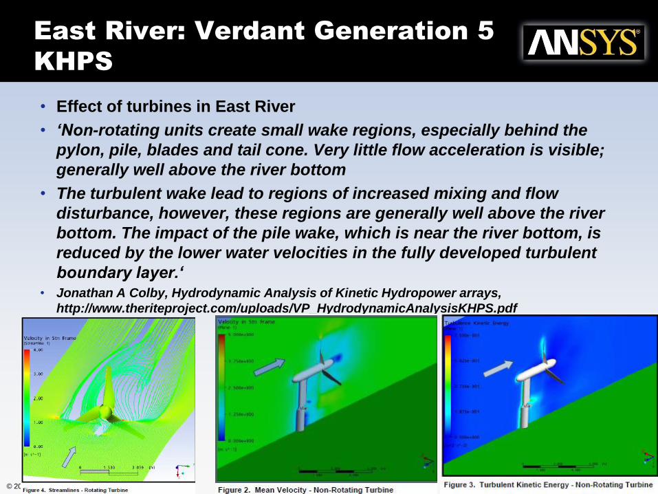
• Effect of turbines in East River
• ‘Non-rotating units create small wake regions, especially behind the
pylon, pile, blades and tail cone. Very little flow acceleration is visible;
generally well above the river bottom
• The turbulent wake lead to regions of increased mixing and flow
disturbance, however, these regions are generally well above the river
bottom. The impact of the pile wake, which is near the river bottom, is
reduced by the lower water velocities in the fully developed turbulent
boundary layer.‘• Jonathan A Colby, Hydrodynamic Analysis of Kinetic Hydropower arrays,
http://www.theriteproject.com/uploads/VP_HydrodynamicAnalysisKHPS.pdf