Embed Size (px)
Citation preview
wet tantalum capacitors vishay
Notes:1. To navigate: a) Click on the vishay logo on any datasheet to go to the Contents page for that section. Click on the vishay logo on any Contents page to go to the main Table of Contents page. b) Click on the products within the Table of Contents to go directly to the datasheet. c) Use the scroll or page up/page down functions. d) Use the adobe® acrobat® page function in the browser bar.
2. To search the text of the catalog use the adobe® acrobat® search function.
vse-db0030-11
INTERACTIVEv i s h a y i N T e R T e C h N O L O G y , i N C .
data book
Discrete Semiconductors and Passive ComponentsOne of the World’s Largest Manufacturers of
V I S H AY I N T E R T E C H N O L O G Y, I N C .
w w w . v i s h a y . c o m
DA
TA
BO
OK
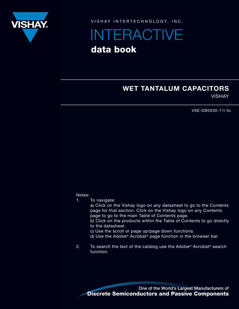
WET TANTALUM CAPACITORSE l a s to m e r S e a l , A x i a l L e a d e d S t y l e s
S u b m i n i a t u r e , A x i a l L e a d e d S t y l e s
H e r m e t i c S e a l , A x i a l L e a d e d S t y l e s
M i l i t a r y M I L- PR F- 3 9 0 0 6 Q u a l i f i e d S t y l e s
S u p e rTa n ® S t y l e s ( S T, S TA , S T E , 9 3 0 26 )
C EC C 3 0 20 2 Q u a l i f i e d S t y l e s
D S C C Q u a l i f i e d S t y l e s
S u r f a c e M o u n t S t y l e s
H i g h E n e r g y C a p a c i to r s
S t a n d a r d a n d C u s to m A r r ay s
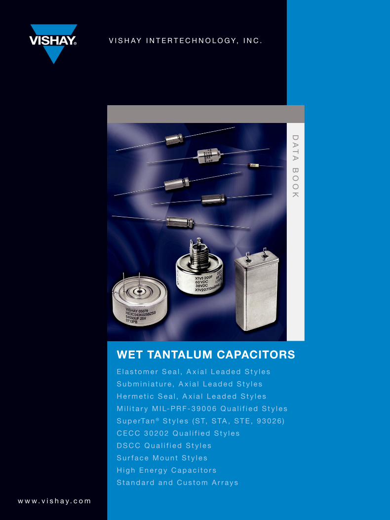
SEMICONDUCTORS
PASSIVE COMPONENTS
PR
OD
UC
T L
IST
ING
S
RECTIFIERS Schottky (single, dual) Standard, Fast and Ultra-Fast Recovery (single, dual) Bridge Superectifier®
Sinterglass Avalanche Diodes
HIGH-POWER DIODES AND THYRISTORS High-Power Fast-Recovery Diodes Phase-Control Thyristors Fast Thyristors
SMALL-SIGNAL DIODES Schottky and Switching (single, dual) Tuner/Capacitance (single, dual) Bandswitching PIN
ZENER AND SUPPRESSOR DIODES Zener (single, dual) TVS (TRANSZORB®, Automotive, ESD, Arrays)
FETs Low-Voltage TrenchFET® Power MOSFETs High-Voltage TrenchFET® Power MOSFETs High-Voltage Planar MOSFETs JFETs
OPTOELECTRONICS IR Emitters and Detectors, and IR Receiver Modules Optocouplers and Solid-State Relays Optical Sensors LEDs and 7-Segment Displays Infrared Data Transceiver Modules Custom Products
ICs Power ICs Analog Switches
MODULES Power Modules (contain power diodes, thyristors, MOSFETs, IGBTs)
RESISTIVE PRODUCTS Film Resistors Metal Film Resistors Thin Film Resistors Thick Film Resistors Metal Oxide Film Resistors Carbon Film Resistors Wirewound Resistors Power Metal Strip® Resistors Chip Fuses Variable Resistors Cermet Variable Resistors Wirewound Variable Resistors Conductive Plastic Variable Resistors Networks/Arrays Non-Linear Resistors NTC Thermistors PTC Thermistors Varistors
MAGNETICS Inductors Transformers
CAPACITORS Tantalum Capacitors Molded Chip Tantalum Capacitors Coated Chip Tantalum Capacitors Solid Through-Hole Tantalum Capacitors Wet Tantalum Capacitors Ceramic Capacitors Multilayer Chip Capacitors Disc Capacitors Film Capacitors Power Capacitors Heavy-Current Capacitors Aluminum Capacitors
Wet Tantalum Capacitors
Vishay Tansitor, Inc.West Road
Bennington VT 05201U. S. A.
Phone: +1 802 442 5473Fax: +1 802 447 1297
www.vishay.com
DISCLAIMER
ALL PRODUCT, PRODUCT SPECIFICATIONS AND DATA ARE SUBJECT TO CHANGE WITHOUT NOTICE TO IMPROVERELIABILITY, FUNCTION OR DESIGN OR OTHERWISE.
Vishay Intertechnology, Inc., its affiliates, agents, and employees, and all persons acting on its or their behalf (collectively,“Vishay”), disclaim any and all liability for any errors, inaccuracies or incompleteness contained in any datasheet or in any otherdisclosure relating to any product.
Vishay makes no warranty, representation or guarantee regarding the suitability of the products for any particular purpose orthe continuing production of any product. To the maximum extent permitted by applicable law, Vishay disclaims (i) any and allliability arising out of the application or use of any product, (ii) any and all liability, including without limitation special,consequential or incidental damages, and (iii) any and all implied warranties, including warranties of fitness for particularpurpose, non-infringement and merchantability.
Statements regarding the suitability of products for certain types of applications are based on Vishay’s knowledge of typicalrequirements that are often placed on Vishay products in generic applications. Such statements are not binding statementsabout the suitability of products for a particular application. It is the customer’s responsibility to validate that a particularproduct with the properties described in the product specification is suitable for use in a particular application. Parametersprovided in datasheets and/or specifications may vary in different applications and performance may vary over time. Alloperating parameters, including typical parameters, must be validated for each customer application by the customer’stechnical experts. Product specifications do not expand or otherwise modify Vishay’s terms and conditions of purchase,including but not limited to the warranty expressed therein.
Except as expressly indicated in writing, Vishay products are not designed for use in medical, life-saving, or life-sustainingapplications or for any other application in which the failure of the Vishay product could result in personal injury or death.Customers using or selling Vishay products not expressly indicated for use in such applications do so at their own risk and agreeto fully indemnify and hold Vishay and its distributors harmless from and against any and all claims, liabilities, expenses anddamages arising or resulting in connection with such use or sale, including attorneys fees, even if such claim alleges that Vishayor its distributor was negligent regarding the design or manufacture of the part. Please contact authorized Vishay personnel toobtain written terms and conditions regarding products designed for such applications.
No license, express or implied, by estoppel or otherwise, to any intellectual property rights is granted by this document or byany conduct of Vishay. Product names and markings noted herein may be trademarks of their respective owners.
For technical questions, contact: [email protected] www.vishay.com1
Wet Tantalum Capacitors
Table of ContentsVishay
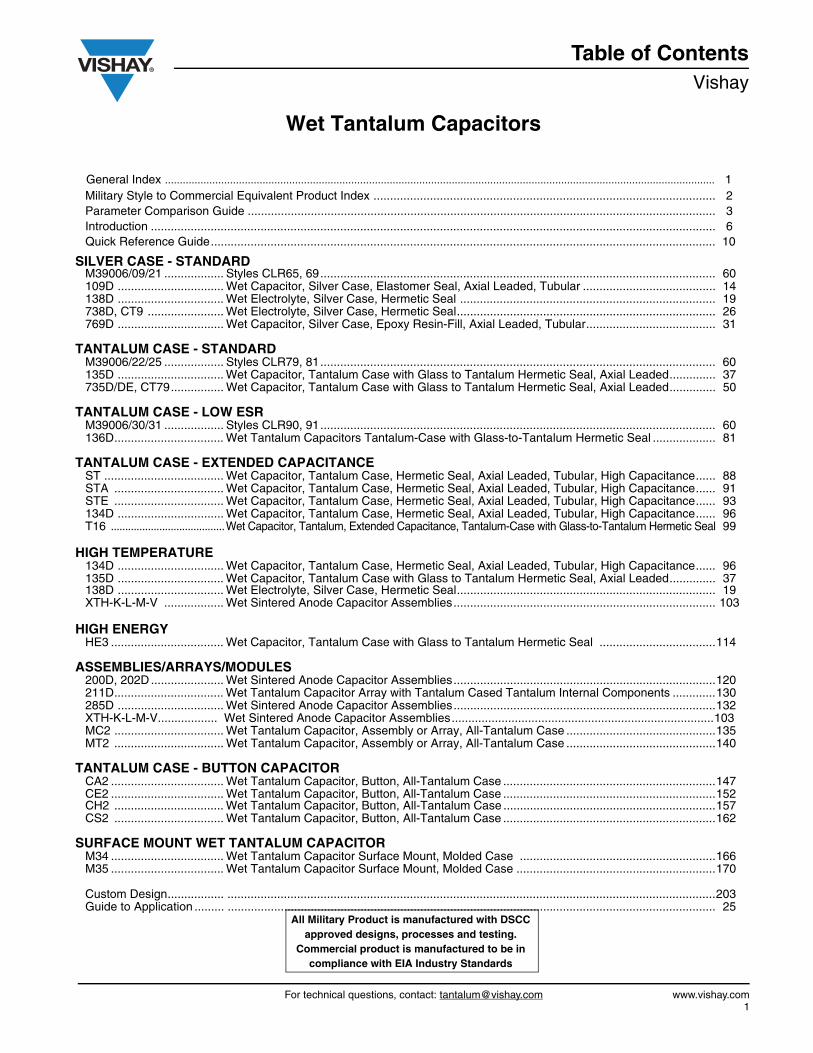
General Index .......................................................................................................................................................................................... 1Military Style to Commercial Equivalent Product Index ....................................................................................................... 2Parameter Comparison Guide ............................................................................................................................................. 3Introduction .......................................................................................................................................................................... 6Quick Reference Guide........................................................................................................................................................ 10
SILVER CASE - STANDARDM39006/09/21 .................. Styles CLR65, 69....................................................................................................................... 60 109D ................................ Wet Capacitor, Silver Case, Elastomer Seal, Axial Leaded, Tubular ........................................ 14138D ................................ Wet Electrolyte, Silver Case, Hermetic Seal ............................................................................. 19738D, CT9 ....................... Wet Electrolyte, Silver Case, Hermetic Seal.............................................................................. 26769D ................................ Wet Capacitor, Silver Case, Epoxy Resin-Fill, Axial Leaded, Tubular....................................... 31
TANTALUM CASE - STANDARDM39006/22/25 .................. Styles CLR79, 81....................................................................................................................... 60 135D ................................ Wet Capacitor, Tantalum Case with Glass to Tantalum Hermetic Seal, Axial Leaded.............. 37735D/DE, CT79................ Wet Capacitor, Tantalum Case with Glass to Tantalum Hermetic Seal, Axial Leaded.............. 50
TANTALUM CASE - LOW ESRM39006/30/31 .................. Styles CLR90, 91....................................................................................................................... 60 136D................................. Wet Tantalum Capacitors Tantalum-Case with Glass-to-Tantalum Hermetic Seal ................... 81
TANTALUM CASE - EXTENDED CAPACITANCEST .................................... Wet Capacitor, Tantalum Case, Hermetic Seal, Axial Leaded, Tubular, High Capacitance...... 88STA ................................. Wet Capacitor, Tantalum Case, Hermetic Seal, Axial Leaded, Tubular, High Capacitance...... 91STE ................................. Wet Capacitor, Tantalum Case, Hermetic Seal, Axial Leaded, Tubular, High Capacitance...... 93134D ................................ Wet Capacitor, Tantalum Case, Hermetic Seal, Axial Leaded, Tubular, High Capacitance...... 96T16 ........................................Wet Capacitor, Tantalum, Extended Capacitance, Tantalum-Case with Glass-to-Tantalum Hermetic Seal 99
HIGH TEMPERATURE134D ................................ Wet Capacitor, Tantalum Case, Hermetic Seal, Axial Leaded, Tubular, High Capacitance...... 96135D ................................ Wet Capacitor, Tantalum Case with Glass to Tantalum Hermetic Seal, Axial Leaded.............. 37138D ................................ Wet Electrolyte, Silver Case, Hermetic Seal.............................................................................. 19XTH-K-L-M-V .................. Wet Sintered Anode Capacitor Assemblies............................................................................... 103
HIGH ENERGYHE3 .................................. Wet Capacitor, Tantalum Case with Glass to Tantalum Hermetic Seal ...................................114
ASSEMBLIES/ARRAYS/MODULES200D, 202D ...................... Wet Sintered Anode Capacitor Assemblies...............................................................................120211D................................. Wet Tantalum Capacitor Array with Tantalum Cased Tantalum Internal Components .............130285D ................................ Wet Sintered Anode Capacitor Assemblies...............................................................................132XTH-K-L-M-V.................. Wet Sintered Anode Capacitor Assemblies...............................................................................103MC2 ................................. Wet Tantalum Capacitor, Assembly or Array, All-Tantalum Case .............................................135MT2 ................................. Wet Tantalum Capacitor, Assembly or Array, All-Tantalum Case .............................................140
TANTALUM CASE - BUTTON CAPACITORCA2 .................................. Wet Tantalum Capacitor, Button, All-Tantalum Case ................................................................147CE2 .................................. Wet Tantalum Capacitor, Button, All-Tantalum Case ................................................................152CH2 ................................. Wet Tantalum Capacitor, Button, All-Tantalum Case ................................................................157CS2 ................................. Wet Tantalum Capacitor, Button, All-Tantalum Case ................................................................162
SURFACE MOUNT WET TANTALUM CAPACITORM34 .................................. Wet Tantalum Capacitor Surface Mount, Molded Case ...........................................................166M35 .................................. Wet Tantalum Capacitor Surface Mount, Molded Case ............................................................170
Custom Design................. ...................................................................................................................................................203Guide to Application ......... ................................................................................................................................................... 25
All Military Product is manufactured with DSCCapproved designs, processes and testing.
Commercial product is manufactured to be in compliance with EIA Industry Standards

Table of ContentsVishay Wet Tantalum Capacitors
www.vishay.com For technical questions, contact: [email protected]
MILITARY PRODUCT INDEX
MILITARY (ESTABLISHED RELIABILITY)MIL-PRF-39006 Qualified, Metal Case, Hermetic Seal, Axial Leaded, Tubular .................................................................. 60M39006/09/21//22/25/30/31 Styles CLR65, 69, 79, 81, 90, 91, Wet Capacitor.................................................................... 60M39006/09, Military Style CLR65, Standard Ratings Chart ................................................................................................. 60M39006/21, Military Style CLR69, Standard Ratings Chart ................................................................................................. 60M39006/22, Military Style CLR79, Standard Ratings Chart ................................................................................................. 60M39006/25, Military Style CLR81, Standard Ratings Chart ................................................................................................. 60M39006/30, Military Style CLR90, Standard Ratings Chart ................................................................................................. 60M39006/31, Military Style CLR91, Standard Ratings Chart ................................................................................................. 60DSCC 06013-06016............................................................................................................................................................. 185
MILITARY (NON-ESTABLISHED RELIABILITY)MIL-DTL-3965/4*, Military Styles CL64/65, Silver Case, Elastomer Seal ............................................................................ 14MIL-DTL-3965/24, Military Style CL66/67, Silver Case, Hermetic Seal ............................................................................... 19MIL-DTL-3965/21, Military Style CL55, Silver Case, Elastomer Seal ..................................................................................147DSCC 04021, Wet Sintered Anode Capacitor Assemblies, Rectangular Metal Case .........................................................120DSCC 04022, Wet Sintered Anode Capacitor Assemblies, Cylindrical Metal Case ............................................................103DSCC 93026, Metal Case, Hermetic Seal, Axial Leaded, Tubular, High Capacitance........................................................175DSCC 10004, Metal Case, Hermetic Seal, Axial Leaded, Tubular, Ultra High ...................................................................178DSCC 10011, Metal Case, Hermetic Seal, Radial Leaded, High Energy ............................................................................180
EUROPEAN APPROVALSCECC 30202 Qualified, Hermetic Seal, Axial Leaded, Tubular30202-001, Style 735D ........................................................................................................................................................ 5030202-004, Style CT9 .......................................................................................................................................................... 2630202-005, Style CT79 ........................................................................................................................................................ 5030202-801, Style 735DE ...................................................................................................................................................... 50
CECC 30202 Qualified, Epoxy Resin End Fill30202-013, Style 769D ........................................................................................................................................................ 31
CECC 30202 Qualified, Metal Case, Button Style30202-002 , CA2 and CE2 Styles ........................................................................................................................................ 147
Note* Type 109D capacitors are commercial equivalents of military style CL64 and CL65 designed to meet the performance requirements of obsolete
Military Specification MIL-C-3965/4.
All Military Product is manufactured with DSCCapproved designs, processes and testing.
Commercial product is manufactured to be in compliance with EIA Industry Standards.
Parameter Comparison Guidewww.vishay.com Vishay
Revision: 18-Nov-11 3 Document Number: 42088
For technical questions, contact: [email protected] DOCUMENT IS SUBJECT TO CHANGE WITHOUT NOTICE. THE PRODUCTS DESCRIBED HEREIN AND THIS DOCUMENT
ARE SUBJECT TO SPECIFIC DISCLAIMERS, SET FORTH AT www.vishay.com/doc?91000
Wet Tantalum Capacitors
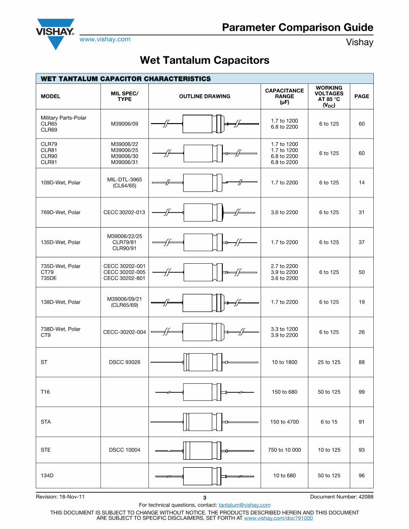
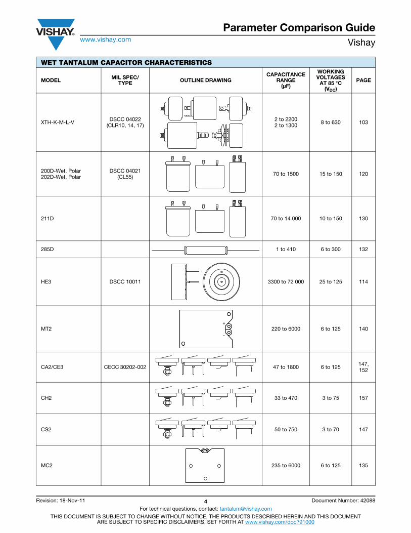
WET TANTALUM CAPACITOR CHARACTERISTICS
MODEL MIL SPEC/TYPE OUTLINE DRAWING
CAPACITANCE RANGE
(μF)
WORKING VOLTAGES
AT 85 °C(VDC)
PAGE
Military Parts-Polar CLR65 CLR69
M39006/09 1.7 to 12006.8 to 2200 6 to 125 60
CLR79 CLR81 CLR90 CLR91
M39006/22 M39006/25 M39006/30 M39006/31
1.7 to 12001.7 to 12006.8 to 22006.8 to 2200
6 to 125 60
109D-Wet, Polar MIL-DTL-3965 (CL64/65) 1.7 to 2200 6 to 125 14
769D-Wet, Polar CECC 30202-013 3.6 to 2200 6 to 125 31
135D-Wet, Polar M39006/22/25
CLR79/81CLR90/91
1.7 to 2200 6 to 125 37
735D-Wet, Polar CT79 735DE
CECC 30202-001CECC 30202-005 CECC 30202-801
2.7 to 22003.9 to 2200 3.6 to 2200
6 to 125 50
138D-Wet, Polar M39006/09/21 (CLR65/69) 1.7 to 2200 6 to 125 19
738D-Wet, Polar CT9 CECC-30202-004 3.3 to 1200
3.9 to 2200 6 to 125 26
ST DSCC 93026 10 to 1800 25 to 125 88
T16 150 to 680 50 to 125 99
STA 150 to 4700 6 to 15 91
STE DSCC 10004 750 to 10 000 10 to 125 93
134D 10 to 680 50 to 125 96
Parameter Comparison Guidewww.vishay.com Vishay
Revision: 18-Nov-11 4 Document Number: 42088
For technical questions, contact: [email protected] DOCUMENT IS SUBJECT TO CHANGE WITHOUT NOTICE. THE PRODUCTS DESCRIBED HEREIN AND THIS DOCUMENT
ARE SUBJECT TO SPECIFIC DISCLAIMERS, SET FORTH AT www.vishay.com/doc?91000
XTH-K-M-L-V DSCC 04022 (CLR10, 14, 17)
2 to 2200 2 to 1300 8 to 630 103
200D-Wet, Polar 202D-Wet, Polar
DSCC 04021(CL55) 70 to 1500 15 to 150 120
211D 70 to 14 000 10 to 150 130
285D 1 to 410 6 to 300 132
HE3 DSCC 10011 3300 to 72 000 25 to 125 114
MT2 220 to 6000 6 to 125 140
CA2/CE3 CECC 30202-002 47 to 1800 6 to 125 147, 152
CH2 33 to 470 3 to 75 157
CS2 50 to 750 3 to 70 147
MC2 235 to 6000 6 to 125 135
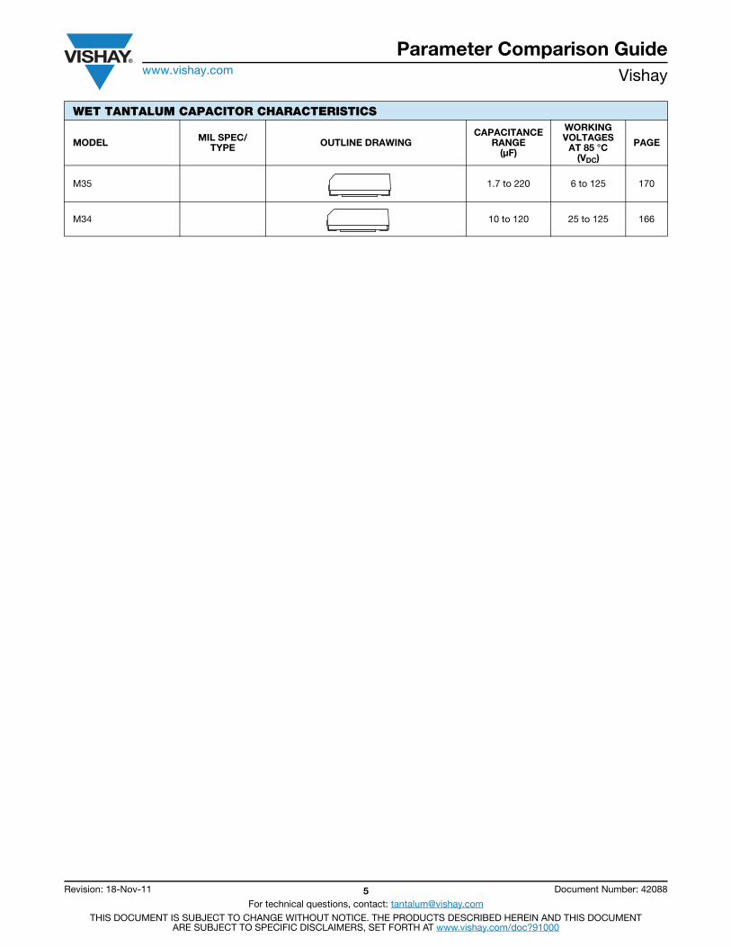
WET TANTALUM CAPACITOR CHARACTERISTICS
MODEL MIL SPEC/TYPE OUTLINE DRAWING
CAPACITANCE RANGE
(μF)
WORKING VOLTAGES
AT 85 °C(VDC)
PAGE
-
+
Parameter Comparison Guidewww.vishay.com Vishay
Revision: 18-Nov-11 5 Document Number: 42088
For technical questions, contact: [email protected] DOCUMENT IS SUBJECT TO CHANGE WITHOUT NOTICE. THE PRODUCTS DESCRIBED HEREIN AND THIS DOCUMENT
ARE SUBJECT TO SPECIFIC DISCLAIMERS, SET FORTH AT www.vishay.com/doc?91000
M35 1.7 to 220 6 to 125 170
M34 10 to 120 25 to 125 166
WET TANTALUM CAPACITOR CHARACTERISTICS
MODEL MIL SPEC/TYPE OUTLINE DRAWING
CAPACITANCE RANGE
(μF)
WORKING VOLTAGES
AT 85 °C(VDC)
PAGE
IntroductionVishay
Document Number: 40021 For technical questions, contact: [email protected] www.vishay.comRevision: 13-Jun-05 6
Wet Electrolytic Tantalum Capacitors
Tantalum electrolytic capacitors are the preferred choice inapplications where volumetric efficiency, stable electricalparameters, high reliability and long service life are theprimary considerations. The stability and resistance toelevated temperatures of the tantalum/tantalum oxidesystem make wet tantalum capacitors an appropriate choicefor today's technology. Vishay is a pioneer and leader in thisfield, producing a large variety of tantalum capacitor types forindustrial, military and aerospace electronic applications.Tantalum is not found in its pure state. Rather, it is commonlyfound in a number of oxide minerals, often in combinationwith Columbium ore. This combination is known as tantalitewhen its contents are more than one-half tantalum. Importantsources of tantalite include Australia, Brazil, Canada, Chinaand several African countries. Synthetic tantaliteconcentrates produced from tin slags in Thailand, Malaysiaand Brazil are also a significant raw material for tantalumproduction.
Electronic applications and particularly capacitors consumethe largest share of world tantalum production. Otherimportant applications for tantalum include cutting tools(tantalum carbide), high temperature super alloys, chemicalprocessing equipment, medical implants and militaryordnance.
Vishay is a major user of tantalum materials in the form ofpowder and wire for capacitor elements and rod and sheetfor high temperature vacuum processing.
THE BASICS OF TANTALUM CAPACITORS TECHNOLOGY
Most metals form crystalline oxides which arenon-protecting, such as rust on iron or black oxide on copper.A few metals form dense, stable, tightly adhering, electricallyinsulating oxides. These are the so-called valve metals andinclude titanium, zirconium, niobium, tantalum, hafnium andaluminum. Only a few of these permit the accurate control ofoxide thickness by electrochemical means. Of these, themost valuable for the electronics industry are aluminum andtantalum.
Wet tantalum capacitors are basic to all kinds of electricalequipment from satellites, aerospace, airborne, militaryground support, oil exploration and power supplies. Theirfunction is to store an electrical charge for later use.
Capacitors consist of two conducting surfaces, usually metalplates, whose function is to conduct electricity. An insulatingmaterial or dielectric separates them . The dielectric used inall tantalum electrolytic capacitors is tantalum pentoxide.
Tantalum pentoxide compound possesses high dielectricstrength and a high dielectric constant. As capacitors arebeing manufactured, a film of tantalum pentoxide is appliedto their electrodes by means of an electronic process. Thefilm is applied in various thicknesses and at various voltagesand although transparent to begin with, it takes on differentcolors as light refracts through it. This coloring occurs on thetantalum electrodes of all types of tantalum capacitors.Rating for rating, tantalum capacitors tend to have as much
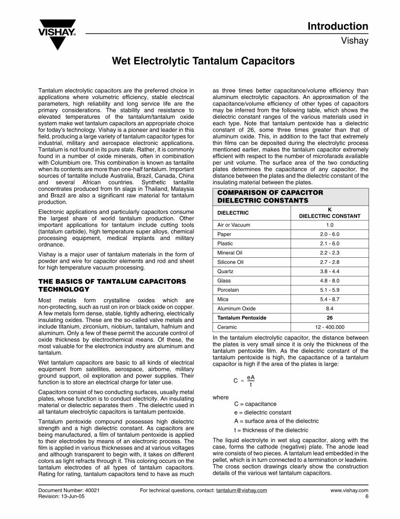
as three times better capacitance/volume efficiency thanaluminum electrolytic capacitors. An approximation of thecapacitance/volume efficiency of other types of capacitorsmay be inferred from the following table, which shows thedielectric constant ranges of the various materials used ineach type. Note that tantalum pentoxide has a dielectricconstant of 26, some three times greater than that ofaluminum oxide. This, in addition to the fact that extremelythin films can be deposited during the electrolytic processmentioned earlier, makes the tantalum capacitor extremelyefficient with respect to the number of microfarads availableper unit volume. The surface area of the two conductingplates determines the capacitance of any capacitor, thedistance between the plates and the dielectric constant of theinsulating material between the plates.
In the tantalum electrolytic capacitor, the distance betweenthe plates is very small since it is only the thickness of thetantalum pentoxide film. As the dielectric constant of thetantalum pentoxide is high, the capacitance of a tantalumcapacitor is high if the area of the plates is large:
whereC = capacitancee = dielectric constant
A = surface area of the dielectric
t = thickness of the dielectric
The liquid electrolyte in wet slug capacitor, along with thecase, forms the cathode (negative) plate. The anode leadwire consists of two pieces. A tantalum lead embedded in thepellet, which is in turn connected to a termination or leadwire.The cross section drawings clearly show the constructiondetails of the various wet tantalum capacitors.
COMPARISON OF CAPACITOR DIELECTRIC CONSTANTS
DIELECTRIC K
DIELECTRIC CONSTANT
Air or Vacuum 1.0
Paper 2.0 - 6.0
Plastic 2.1 - 6.0
Mineral Oil 2.2 - 2.3
Silicone Oil 2.7 - 2.8
Quartz 3.8 - 4.4
Glass 4.8 - 8.0
Porcelain 5.1 - 5.9
Mica 5.4 - 8.7
Aluminum Oxide 8.4
Tantalum Pentoxide 26
Ceramic 12 - 400.000
C eAt
-------=
www.vishay.com For technical questions, contact: [email protected] Document Number: 400217 Revision: 13-Jun-05
IntroductionVishay Wet Electrolytic Tantalum Capacitors
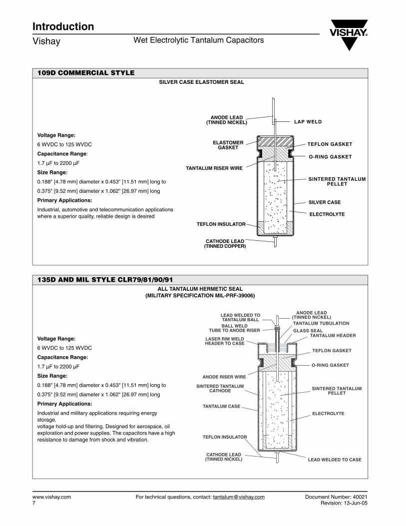
109D COMMERCIAL STYLESILVER CASE ELASTOMER SEAL
Voltage Range:
6 WVDC to 125 WVDC
Capacitance Range:
1.7 µF to 2200 µF
Size Range:
0.188" [4.78 mm] diameter x 0.453" [11.51 mm] long to
0.375" [9.52 mm] diameter x 1.062" [26.97 mm] long
Primary Applications:
Industrial, automotive and telecommunication applicationswhere a superior quality, reliable design is desired
ANODE LEAD(TINNED NICKEL)
ELASTOMERGASKET
TANTALUM RISER WIRE
SILVER CASE
ELECTROLYTE
CATHODE LEAD(TINNED COPPER)
TEFLON INSULATOR
SINTERED TANTALUMPELLET
O-RING GASKET
TEFLON GASKET
LAP WELD
135D AND MIL STYLE CLR79/81/90/91ALL TANTALUM HERMETIC SEAL
(MILITARY SPECIFICATION MIL-PRF-39006)
Voltage Range:
6 WVDC to 125 WVDC
Capacitance Range:
1.7 µF to 2200 µF
Size Range:
0.188" [4.78 mm] diameter x 0.453" [11.51 mm] long to
0.375" [9.52 mm] diameter x 1.062" [26.97 mm] long
Primary Applications:
Industrial and military applications requiring energy storage, voltage hold-up and filtering. Designed for aerospace, oil exploration and power supplies. The capacitors have a high resistance to damage from shock and vibration.
LEAD WELDED TOTANTALUM BALLBALL WELD
TUBE TO ANODE RISER
LASER RIM WELDHEADER TO CASE
ANODE RISER WIRE
TANTALUM CASE
ELECTROLYTE
TEFLON INSULATOR
CATHODE LEAD(TINNED NICKEL) LEAD WELDED TO CASE
SINTERED TANTALUMPELLET
O-RING GASKET
TEFLON GASKET
TANTALUM HEADERGLASS SEAL
TANTALUM TUBULATION
ANODE LEAD(TINNED NICKEL)
SINTERED TANTALUMCATHODE
Document Number: 40021 For technical questions, contact: [email protected] www.vishay.comRevision: 13-Jun-05 8
IntroductionWet Electrolytic Tantalum Capacitors Vishay
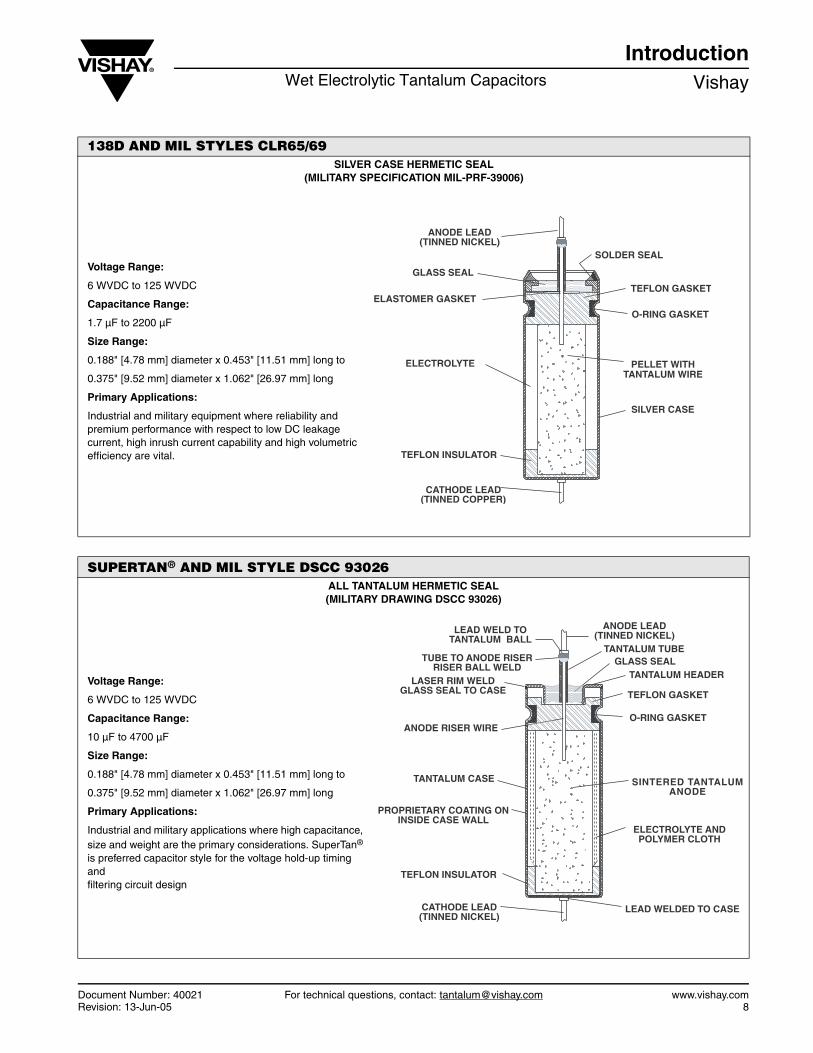
138D AND MIL STYLES CLR65/69SILVER CASE HERMETIC SEAL
(MILITARY SPECIFICATION MIL-PRF-39006)
Voltage Range:
6 WVDC to 125 WVDC
Capacitance Range:
1.7 µF to 2200 µF
Size Range:
0.188" [4.78 mm] diameter x 0.453" [11.51 mm] long to
0.375" [9.52 mm] diameter x 1.062" [26.97 mm] long
Primary Applications:
Industrial and military equipment where reliability and premium performance with respect to low DC leakage current, high inrush current capability and high volumetric efficiency are vital.
ANODE LEAD(TINNED NICKEL)
GLASS SEAL
ELASTOMER GASKET
ELECTROLYTE
SILVER CASE
TEFLON INSULATOR
CATHODE LEAD(TINNED COPPER)
PELLET WITHTANTALUM WIRE
O-RING GASKET
TEFLON GASKET
SOLDER SEAL
SUPERTAN® AND MIL STYLE DSCC 93026ALL TANTALUM HERMETIC SEAL (MILITARY DRAWING DSCC 93026)
Voltage Range:
6 WVDC to 125 WVDC
Capacitance Range:
10 µF to 4700 µF
Size Range:
0.188" [4.78 mm] diameter x 0.453" [11.51 mm] long to
0.375" [9.52 mm] diameter x 1.062" [26.97 mm] long
Primary Applications:
Industrial and military applications where high capacitance, size and weight are the primary considerations. SuperTan® is preferred capacitor style for the voltage hold-up timing and filtering circuit design
LEAD WELD TOTANTALUM BALL
TUBE TO ANODE RISERRISER BALL WELD
LASER RIM WELDGLASS SEAL TO CASE
ANODE RISER WIRE
TANTALUM CASE
TEFLON INSULATOR
CATHODE LEAD(TINNED NICKEL)
LEAD WELDED TO CASE
ELECTROLYTE ANDPOLYMER CLOTH
O-RING GASKET
TEFLON GASKET
TANTALUM HEADERGLASS SEAL
TANTALUM TUBE
ANODE LEAD(TINNED NICKEL)
SINTERED TANTALUMANODE
PROPRIETARY COATING ONINSIDE CASE WALL
www.vishay.com For technical questions, contact: [email protected] Document Number: 400219 Revision: 13-Jun-05
IntroductionVishay Wet Electrolytic Tantalum Capacitors
WET ELECTROLYTE TANTALUM CAPACITORS
Wet electrolyte, sintered anode tantalum capacitors oftencalled wet slug tantalum capacitors, use a pellet of sinteredtantalum power to which a lead has been attached.
Tantalum powder of suitable fineness, sometimes mixed withbinding agents, is mechanically pressed into pellets.
The lead is embedded during pressing of the pellet. The nextstep is a sintering operation in which binders, impurities andcontaminants are vaporized and the tantalum particles aresintered into a porous mass with a very large surface area.
A film of tantalum pentoxide is electrochemically formed onthe surface areas of the fused tantalum particles. Providedsufficient time and current is available, the oxide will grow toa thickness determined by the applied voltage.
The pellet is then inserted into a tantalum or silver can, whichcontains an electrolyte solution, A suitable end sealarrangement prevents the loss of the electrolyte.
Wet slug tantalum capacitors are manufactured in a voltagerange up to 125 WVDC.
The Vishay SuperTan® represents a major breakthrough intantalum electrolyte capacitor design. The SuperTan designdramatically increased the available capacitance in each ofthe four standard cased sizes. It provides two to three timesmore capacitance per unit volume while substantiallyincreasing ripple current capability as well as reduced ESR.
In airborne, aerospace, satellite and smart munitionsapplications where size and weight are the primaryconsiderations, SuperTan is the preferred capacitor style forthe energy storage, voltage hold-up, timing and filteringcircuit design. With these circuit functions in mind, along withlong-term shelf life, operation life and reliability, SuperTanprovides the circuit designer a solution to many of theproblems that previously were resolved with marginallyreliable and ineffective size options.
SuperTan is available to the military sector on a DSCCapproved drawing (93026) as well to the commercial sectoras a standard device.
TANTALUM CAPACITORS FOR ALL DESIGN CONSIDERATIONS
In choosing between the solid or wet style of tantalumcapacitor, the circuit designer customarily uses wet tantalumcapacitors, where the lowest DC leakage is required. Theconventional silver can design will not tolerate any reversevoltages. In military or aerospace applications, tantalumcases units are used in place of silver cases where theutmost reliability is desired. The tantalum cased styles,CLR79 and CLR81, will withstand reverse voltages up to 3 V.They will operate under higher ripple currents and can beused at temperatures up to + 392 °F (+ 200 °C).
Vishay has the broadest line of tantalum capacitors and hascontinued its position of leadership in this field. Data sheetscovering the various types and styles of Vishay capacitors forindustry and for military applications are available on theVishay web site: www.vishay.com
Quick Reference Guidewww.vishay.com Vishay
Revision: 18-Nov-11 10 Document Number: 40056
For technical questions, contact: [email protected] DOCUMENT IS SUBJECT TO CHANGE WITHOUT NOTICE. THE PRODUCTS DESCRIBED HEREIN AND THIS DOCUMENT
ARE SUBJECT TO SPECIFIC DISCLAIMERS, SET FORTH AT www.vishay.com/doc?91000
Wet Tantalum Capacitors
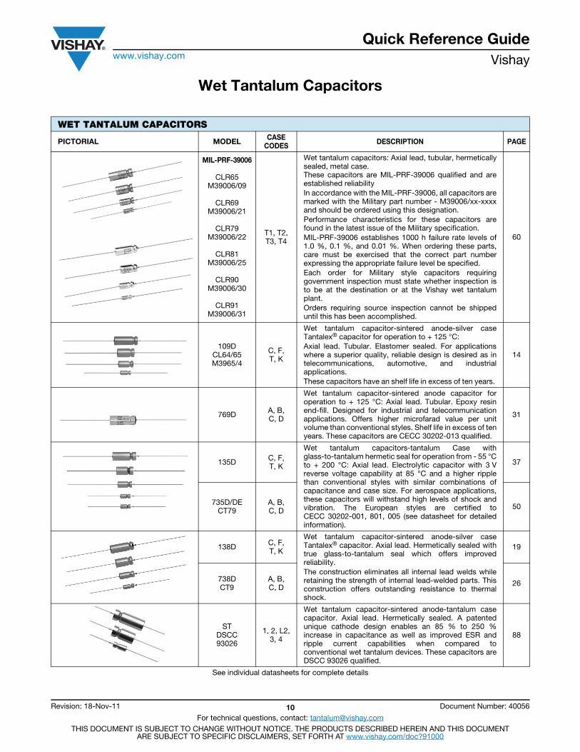
WET TANTALUM CAPACITORS
PICTORIAL MODEL CASE CODES DESCRIPTION PAGE
MIL-PRF-39006
CLR65 M39006/09
CLR69 M39006/21
CLR79 M39006/22
CLR81 M39006/25
CLR90 M39006/30
CLR91 M39006/31
T1, T2, T3, T4
Wet tantalum capacitors: Axial lead, tubular, hermeticallysealed, metal case. These capacitors are MIL-PRF-39006 qualified and areestablished reliability In accordance with the MIL-PRF-39006, all capacitors aremarked with the Military part number - M39006/xx-xxxxand should be ordered using this designation. Performance characteristics for these capacitors arefound in the latest issue of the Military specification. MIL-PRF-39006 establishes 1000 h failure rate levels of1.0 %, 0.1 %, and 0.01 %. When ordering these parts,care must be exercised that the correct part numberexpressing the appropriate failure level be specified. Each order for Military style capacitors requiringgovernment inspection must state whether inspection isto be at the destination or at the Vishay wet tantalumplant. Orders requiring source inspection cannot be shippeduntil this has been accomplished.
60
109D CL64/65 M3965/4
C, F, T, K
Wet tantalum capacitor-sintered anode-silver caseTantalex® capacitor for operation to + 125 °C: Axial lead. Tubular. Elastomer sealed. For applicationswhere a superior quality, reliable design is desired as intelecommunications, automotive, and industrialapplications. These capacitors have an shelf life in excess of ten years.
14
769D A, B, C, D
Wet tantalum capacitor-sintered anode capacitor foroperation to + 125 °C: Axial lead. Tubular. Epoxy resinend-fill. Designed for industrial and telecommunicationapplications. Offers higher microfarad value per unitvolume than conventional styles. Shelf life in excess of tenyears. These capacitors are CECC 30202-013 qualified.
31
135D C, F, T, K
Wet tantalum capacitors-tantalum Case withglass-to-tantalum hermetic seal for operation from - 55 °Cto + 200 °C: Axial lead. Electrolytic capacitor with 3 Vreverse voltage capability at 85 °C and a higher ripplethan conventional styles with similar combinations ofcapacitance and case size. For aerospace applications,these capacitors will withstand high levels of shock andvibration. The European styles are certified toCECC 30202-001, 801, 005 (see datasheet for detailedinformation).
37
735D/DECT79
A, B,C, D 50
138D C, F, T, K
Wet tantalum capacitor-sintered anode-silver caseTantalex® capacitor. Axial lead. Hermetically sealed withtrue glass-to-tantalum seal which offers improvedreliability. The construction eliminates all internal lead welds whileretaining the strength of internal lead-welded parts. Thisconstruction offers outstanding resistance to thermalshock.
19
738DCT9
A, B, C, D 26
ST DSCC 93026
1, 2, L2,3, 4
Wet tantalum capacitor-sintered anode-tantalum casecapacitor. Axial lead. Hermetically sealed. A patentedunique cathode design enables an 85 % to 250 %increase in capacitance as well as improved ESR andripple current capabilities when compared toconventional wet tantalum devices. These capacitors areDSCC 93026 qualified.
88
See individual datasheets for complete details
Quick Reference Guidewww.vishay.com Vishay
Revision: 18-Nov-11 11 Document Number: 40056
For technical questions, contact: [email protected] DOCUMENT IS SUBJECT TO CHANGE WITHOUT NOTICE. THE PRODUCTS DESCRIBED HEREIN AND THIS DOCUMENT
ARE SUBJECT TO SPECIFIC DISCLAIMERS, SET FORTH AT www.vishay.com/doc?91000
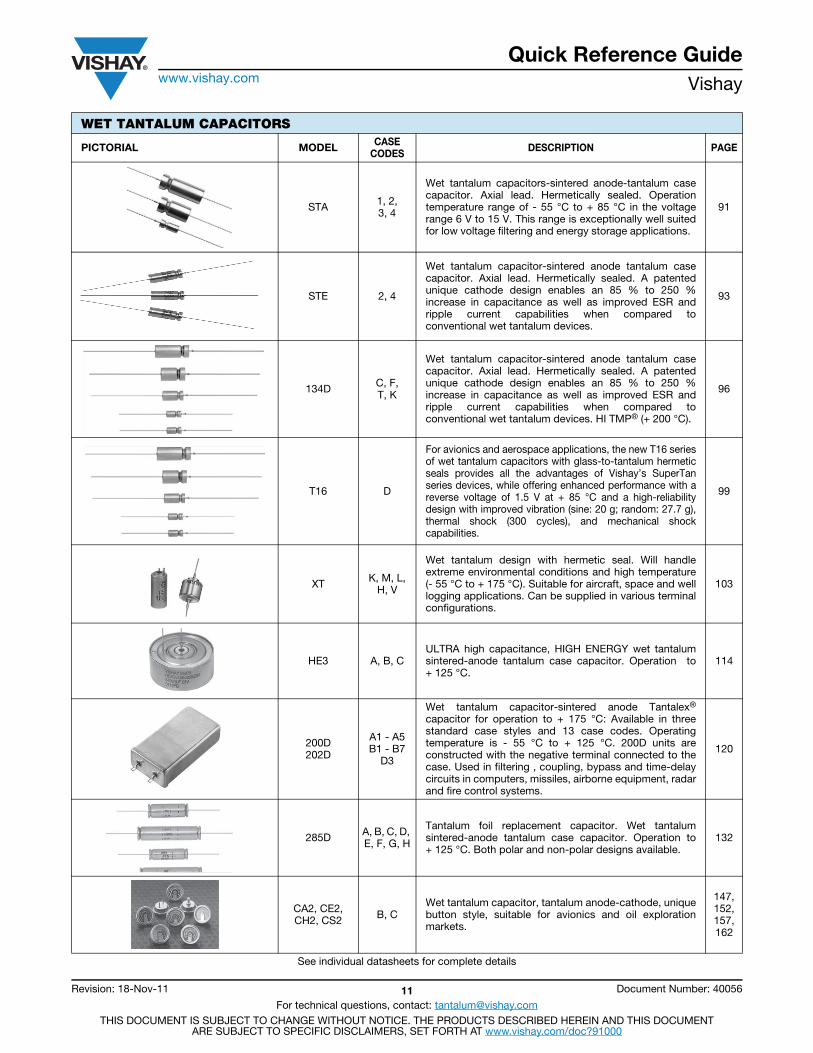
STA 1, 2,3, 4
Wet tantalum capacitors-sintered anode-tantalum casecapacitor. Axial lead. Hermetically sealed. Operationtemperature range of - 55 °C to + 85 °C in the voltagerange 6 V to 15 V. This range is exceptionally well suitedfor low voltage filtering and energy storage applications.
91
STE 2, 4
Wet tantalum capacitor-sintered anode tantalum casecapacitor. Axial lead. Hermetically sealed. A patentedunique cathode design enables an 85 % to 250 %increase in capacitance as well as improved ESR andripple current capabilities when compared toconventional wet tantalum devices.
93
134D C, F, T, K
Wet tantalum capacitor-sintered anode tantalum casecapacitor. Axial lead. Hermetically sealed. A patentedunique cathode design enables an 85 % to 250 %increase in capacitance as well as improved ESR andripple current capabilities when compared toconventional wet tantalum devices. HI TMP® (+ 200 °C).
96
T16 D
For avionics and aerospace applications, the new T16 seriesof wet tantalum capacitors with glass-to-tantalum hermeticseals provides all the advantages of Vishay’s SuperTanseries devices, while offering enhanced performance with areverse voltage of 1.5 V at + 85 °C and a high-reliabilitydesign with improved vibration (sine: 20 g; random: 27.7 g),thermal shock (300 cycles), and mechanical shockcapabilities.
99
XT K, M, L, H, V
Wet tantalum design with hermetic seal. Will handleextreme environmental conditions and high temperature(- 55 °C to + 175 °C). Suitable for aircraft, space and welllogging applications. Can be supplied in various terminalconfigurations.
103
HE3 A, B, CULTRA high capacitance, HIGH ENERGY wet tantalumsintered-anode tantalum case capacitor. Operation to+ 125 °C.
114
200D202D
A1 - A5 B1 - B7
D3
Wet tantalum capacitor-sintered anode Tantalex®
capacitor for operation to + 175 °C: Available in threestandard case styles and 13 case codes. Operatingtemperature is - 55 °C to + 125 °C. 200D units areconstructed with the negative terminal connected to thecase. Used in filtering , coupling, bypass and time-delaycircuits in computers, missiles, airborne equipment, radarand fire control systems.
120
285D A, B, C, D, E, F, G, H
Tantalum foil replacement capacitor. Wet tantalumsintered-anode tantalum case capacitor. Operation to+ 125 °C. Both polar and non-polar designs available.
132
CA2, CE2, CH2, CS2 B, C
Wet tantalum capacitor, tantalum anode-cathode, uniquebutton style, suitable for avionics and oil explorationmarkets.
147, 152, 157, 162
WET TANTALUM CAPACITORS
PICTORIAL MODEL CASE CODES DESCRIPTION PAGE
See individual datasheets for complete details

Quick Reference Guidewww.vishay.com Vishay
Revision: 18-Nov-11 12 Document Number: 40056
For technical questions, contact: [email protected] DOCUMENT IS SUBJECT TO CHANGE WITHOUT NOTICE. THE PRODUCTS DESCRIBED HEREIN AND THIS DOCUMENT
ARE SUBJECT TO SPECIFIC DISCLAIMERS, SET FORTH AT www.vishay.com/doc?91000
M34, M35 CWet tantalum capacitor, tantalum anode-cathode,surface mount package, suitable for military and avionicsapplications.
166, 170
Custom Design Arrays
contact: wettants@ vishay.com
Vishay offers a complete design service to provide thebest technical and commercial solution. This serviceincludes assistance preparing specifications and makingsamples, special testing, evaluating test results andmaking any necessary changes to achieve the ultimate indesign.
203
WET TANTALUM CAPACITORS
PICTORIAL MODEL CASE CODES DESCRIPTION PAGE
See individual datasheets for complete details
Contents
M39006/09/21 ................ 60
109D .............................. 14
138D .............................. 19
738D, CT9 ..................... 26
769D .............................. 31Silver Case Standard
109DVishay
Wet Tantalum Capacitors Sintered Anode TANTALEX® Capacitorsfor Operation to 125 °C, Elastomer Sealed
www.vishay.com For technical questions, contact: [email protected] Document Number: 4002314 Revision: 21-Jan-11
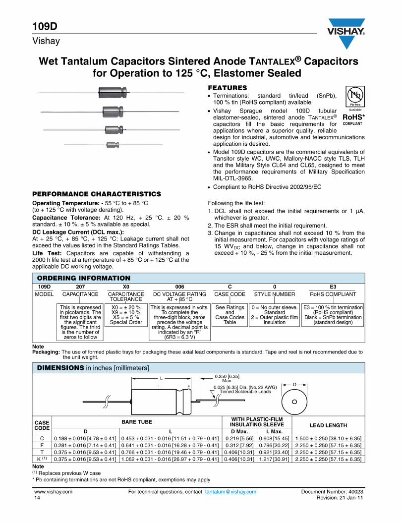
FEATURES Terminations: standard tin/lead (SnPb),
100 % tin (RoHS compliant) available Vishay Sprague model 109D tubular
elastomer-sealed, sintered anode TANTALEX®
capacitors fill the basic requirements forapplications where a superior quality, reliabledesign for industrial, automotive and telecommunicationsapplication is desired.
Model 109D capacitors are the commercial equivalents ofTansitor style WC, UWC, Mallory-NACC style TLS, TLHand the Military Style CL64 and CL65, designed to meetthe performance requirements of Military SpecificationMIL-DTL-3965.
Compliant to RoHS Directive 2002/95/ECPERFORMANCE CHARACTERISTICSOperating Temperature: - 55 °C to + 85 °C (to + 125 °C with voltage derating).Capacitance Tolerance: At 120 Hz, + 25 °C. ± 20 %standard. ± 10 %, ± 5 % available as special.DC Leakage Current (DCL max.):At + 25 °C, + 85 °C, + 125 °C: Leakage current shall notexceed the values listed in the Standard Ratings Tables.Life Test: Capacitors are capable of withstanding a2000 h life test at a temperature of + 85 °C or + 125 °C at theapplicable DC working voltage.
Following the life test:1. DCL shall not exceed the initial requirements or 1 µA,
whichever is greater.2. The ESR shall meet the initial requirement.3. Change in capacitance shall not exceed 10 % from the
initial measurement. For capacitors with voltage ratings of15 WVDC and below, change in capacitance shall notexceed + 10 %, - 25 % from the initial measurement.
Note(1) Replaces previous W case* Pb containing terminations are not RoHS compliant, exemptions may apply
ORDERING INFORMATION109D 207 X0 006 C 0 E3
MODEL CAPACITANCE CAPACITANCE TOLERANCE
DC VOLTAGE RATING AT + 85 C
CASE CODE STYLE NUMBER RoHS COMPLIANT
This is expressed in picofarads. The first two digits are
the significant figures. The third is the number of zeros to follow
X0 = ± 20 % X9 = ± 10 %X5 = ± 5 %
Special Order
This is expressed in volts. To complete the
three-digit block, zeros precede the voltage
rating. A decimal point is indicated by an “R”
(6R3 = 6.3 V)
See Ratingsand
Case CodesTable
0 = No outer sleeve. Standard
2 = Outer plastic film insulation
E3 = 100 % tin termination(RoHS compliant)
Blank = SnPb termination(standard design)
NotePackaging: The use of formed plastic trays for packaging these axial lead components is standard. Tape and reel is not recommended due to
the unit weight.
DIMENSIONS in inches [millimeters]
CASE CODE
BARE TUBE WITH PLASTIC-FILM INSULATING SLEEVE LEAD LENGTH
D L D Max. L Max.C 0.188 ± 0.016 [4.78 ± 0.41] 0.453 + 0.031 - 0.016 [11.51 + 0.79 - 0.41] 0.219 [5.56] 0.608 [15.45] 1.500 ± 0.250 [38.10 ± 6.35] F 0.281 ± 0.016 [7.14 ± 0.41] 0.641 + 0.031 - 0.016 [16.28 + 0.79 - 0.41] 0.312 [7.92] 0.796 [20.22] 2.250 ± 0.250 [57.15 ± 6.35] T 0.375 ± 0.016 [9.53 ± 0.41] 0.766 + 0.031 - 0.016 [19.46 + 0.79 - 0.41] 0.406 [10.31] 0.921 [23.40] 2.250 ± 0.250 [57.15 ± 6.35]
K (1) 0.375 ± 0.016 [9.53 ± 0.41] 1.062 + 0.031 - 0.016 [26.97 + 0.79 - 0.41] 0.406 [10.31] 1.217 [30.91] 2.250 ± 0.250 [57.15 ± 6.35]
- + 0.025 [6.35] Dia. (No. 22 AWG)Tinned Solderable Leads
D
0.250 [6.35]Max.L
Document Number: 40023 For technical questions, contact: [email protected] www.vishay.comRevision: 21-Jan-11 15
109DWet Tantalum Capacitors Sintered Anode TANTALEX® Capacitors
for Operation to 125 °C, Elastomer Sealed Vishay
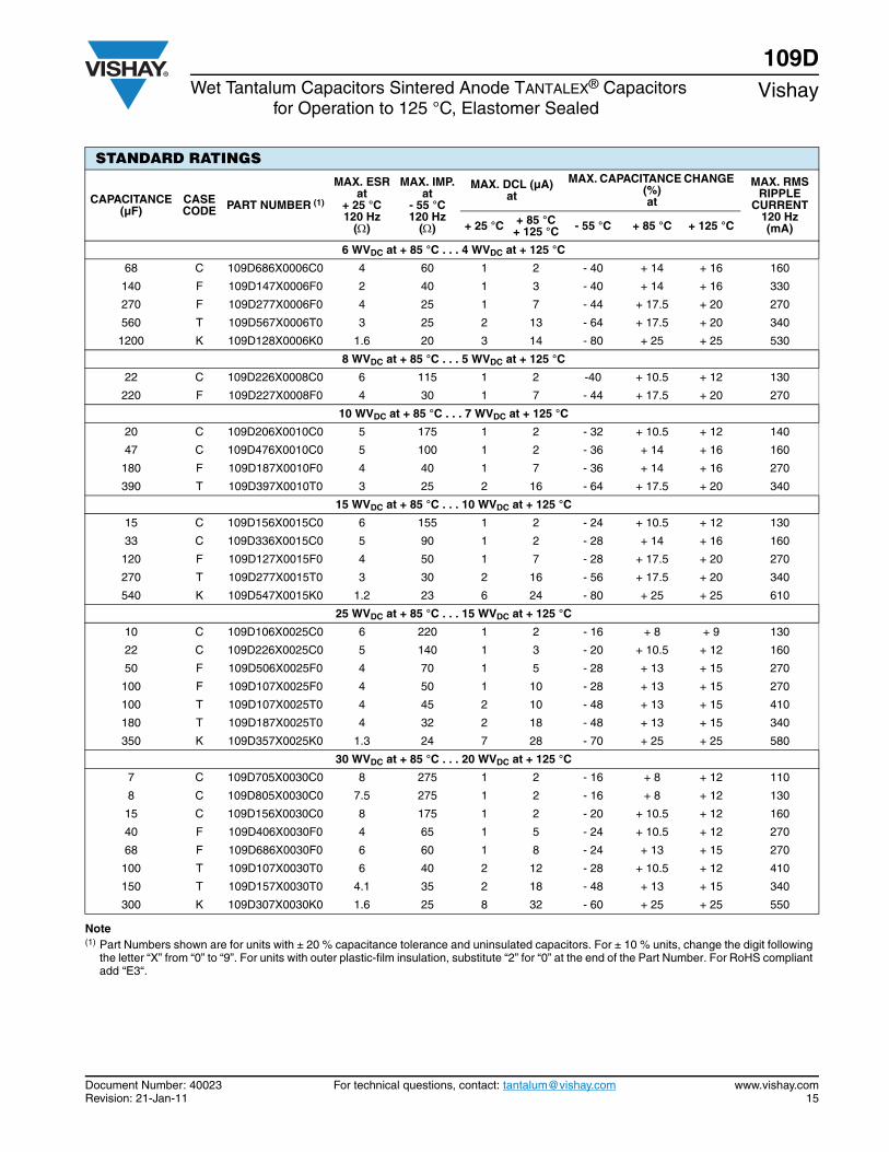
STANDARD RATINGS
CAPACITANCE (µF)
CASE CODE PART NUMBER (1)
MAX. ESRat
+ 25 °C 120 Hz
()
MAX. IMP.at
- 55 °C120 Hz
()
MAX. DCL (µA)at
MAX. CAPACITANCE CHANGE (%)at
MAX. RMSRIPPLE
CURRENT120 Hz (mA)+ 25 °C + 85 °C
+ 125 °C - 55 °C + 85 °C + 125 °C
6 WVDC at + 85 °C . . . 4 WVDC at + 125 °C
68 C 109D686X0006C0 4 60 1 2 - 40 + 14 + 16 160
140 F 109D147X0006F0 2 40 1 3 - 40 + 14 + 16 330
270 F 109D277X0006F0 4 25 1 7 - 44 + 17.5 + 20 270
560 T 109D567X0006T0 3 25 2 13 - 64 + 17.5 + 20 340
1200 K 109D128X0006K0 1.6 20 3 14 - 80 + 25 + 25 530
8 WVDC at + 85 °C . . . 5 WVDC at + 125 °C
22 C 109D226X0008C0 6 115 1 2 -40 + 10.5 + 12 130
220 F 109D227X0008F0 4 30 1 7 - 44 + 17.5 + 20 270
10 WVDC at + 85 °C . . . 7 WVDC at + 125 °C
20 C 109D206X0010C0 5 175 1 2 - 32 + 10.5 + 12 140
47 C 109D476X0010C0 5 100 1 2 - 36 + 14 + 16 160
180 F 109D187X0010F0 4 40 1 7 - 36 + 14 + 16 270
390 T 109D397X0010T0 3 25 2 16 - 64 + 17.5 + 20 340
15 WVDC at + 85 °C . . . 10 WVDC at + 125 °C
15 C 109D156X0015C0 6 155 1 2 - 24 + 10.5 + 12 130
33 C 109D336X0015C0 5 90 1 2 - 28 + 14 + 16 160
120 F 109D127X0015F0 4 50 1 7 - 28 + 17.5 + 20 270
270 T 109D277X0015T0 3 30 2 16 - 56 + 17.5 + 20 340
540 K 109D547X0015K0 1.2 23 6 24 - 80 + 25 + 25 610
25 WVDC at + 85 °C . . . 15 WVDC at + 125 °C
10 C 109D106X0025C0 6 220 1 2 - 16 + 8 + 9 130
22 C 109D226X0025C0 5 140 1 3 - 20 + 10.5 + 12 160
50 F 109D506X0025F0 4 70 1 5 - 28 + 13 + 15 270
100 F 109D107X0025F0 4 50 1 10 - 28 + 13 + 15 270
100 T 109D107X0025T0 4 45 2 10 - 48 + 13 + 15 410
180 T 109D187X0025T0 4 32 2 18 - 48 + 13 + 15 340
350 K 109D357X0025K0 1.3 24 7 28 - 70 + 25 + 25 580
30 WVDC at + 85 °C . . . 20 WVDC at + 125 °C
7 C 109D705X0030C0 8 275 1 2 - 16 + 8 + 12 110
8 C 109D805X0030C0 7.5 275 1 2 - 16 + 8 + 12 130
15 C 109D156X0030C0 8 175 1 2 - 20 + 10.5 + 12 160
40 F 109D406X0030F0 4 65 1 5 - 24 + 10.5 + 12 270
68 F 109D686X0030F0 6 60 1 8 - 24 + 13 + 15 270
100 T 109D107X0030T0 6 40 2 12 - 28 + 10.5 + 12 410
150 T 109D157X0030T0 4.1 35 2 18 - 48 + 13 + 15 340
300 K 109D307X0030K0 1.6 25 8 32 - 60 + 25 + 25 550
Note(1) Part Numbers shown are for units with ± 20 % capacitance tolerance and uninsulated capacitors. For ± 10 % units, change the digit following
the letter “X” from “0” to “9”. For units with outer plastic-film insulation, substitute “2” for “0” at the end of the Part Number. For RoHS compliantadd “E3“.
109DVishay Wet Tantalum Capacitors Sintered Anode TANTALEX® Capacitors
for Operation to 125 °C, Elastomer Sealed
www.vishay.com For technical questions, contact: [email protected] Document Number: 4002316 Revision: 21-Jan-11
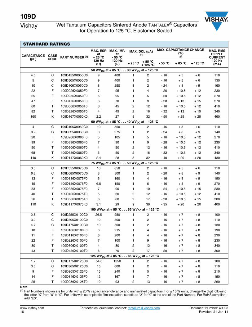
50 WVDC at + 85 °C . . . 30 WVDC at + 125 °C
4.5 C 109D455X0050C0 9 400 1 2 - 16 + 5 + 6 110
5 C 109D505X0050C0 9 400 1 2 - 16 + 5 + 6 130
10 C 109D106X0050C0 8 250 1 2 - 24 + 8 + 9 160
22 F 109D226X0050F0 7 95 1 4 - 20 + 10.5 + 12 230
25 F 109D256X0050F0 6 95 1 5 - 20 + 10.5 + 12 270
47 F 109D476X0050F0 6 70 1 9 - 28 + 13 + 15 270
60 T 109D606X0050T0 3 45 2 12 - 16 + 10.5 + 12 410
82 T 109D826X0050T0 4 45 2 16 - 32 + 13 + 15 340
160 K 109D167X0050K0 2.2 27 8 32 - 50 + 25 + 25 460
60 WVDC at + 85 °C . . . 40 WVDC at + 125 °C
4 C 109D405X0060C0 10 550 1 2 - 16 + 5 + 6 110
8.2 C 109D825X0060C0 8 275 1 2 - 24 + 8 + 9 140
20 F 109D206X0060F0 5 105 1 5 - 16 + 10.5 + 12 270
39 F 109D396X0060F0 7 90 1 9 - 28 + 10.5 + 12 230
50 T 109D506X0060T0 4 50 2 12 - 16 + 10.5 + 12 410
68 T 109D686X0060T0 6 50 2 16 - 32 + 10.5 + 12 340
140 K 109D147X0060K0 2.4 28 8 32 - 40 + 20 + 20 430
75 WVDC at + 85 °C . . . 50 WVDC at + 125 °C
3.5 C 109D355X0075C0 10 650 1 2 - 16 + 5 + 6 110
6.8 C 109D685X0075C0 8 300 1 2 - 20 + 8 + 9 140
13 F 109D136X0075F0 6 160 1 4 - 16 + 8 + 9 190
15 F 109D156X0075F0 6.5 150 1 5 - 16 + 8 + 9 270
33 F 109D336X0075F0 7 90 1 10 - 24 + 10.5 + 15 230
40 T 109D406X0075T0 5 60 2 12 - 16 + 10.5 + 12 410
56 T 109D566X0075T0 6 60 2 17 - 28 + 10.5 + 15 300
110 K 109D117X0075K0 3.1 29 9 36 - 35 + 20 + 20 400
100 WVDC at + 85 °C . . . 65 WVDC at + 125 °C
2.5 C 109D255X0100C0 26.5 950 1 2 - 16 + 7 + 8 100
3.0 C 109D305X0100C0 10 800 1 2 - 16 + 7 + 8 110
4.7 C 109D475X0100C0 10 500 1 2 - 16 + 7 + 8 130
10 F 109D106X0100F0 6 215 1 4 - 16 + 7 + 8 190
11 F 109D116X0100F0 6 200 1 4 - 16 + 7 + 8 230
22 F 109D226X0100F0 7 100 1 9 - 16 + 7 + 8 230
30 T 109D306X0100T0 4 80 2 12 - 16 + 7 + 8 340
43 T 109D436X0100T0 6 70 2 17 - 20 + 7 + 8 300
125 WVDC at + 85 °C . . . 85 WVDC at + 125 °C
1.7 C 109D175X0125C0 54.6 1250 1 2 - 16 + 7 + 8 100
3.6 C 109D365X0125C0 15 600 1 2 - 16 + 7 + 8 110
9 F 109D905X0125F0 15 240 1 5 - 16 + 7 + 8 210
14 F 109D146X0125F0 12 167 1 7 - 16 + 7 + 8 190
25 T 109D256X0125T0 10 93 2 13 - 16 + 7 + 8 260
Note(1) Part Numbers shown are for units with ± 20 % capacitance tolerance and uninsulated capacitors. For ± 10 % units, change the digit following
the letter “X” from “0” to “9”. For units with outer plastic-film insulation, substitute “2” for “0” at the end of the Part Number. For RoHS compliantadd “E3“.
STANDARD RATINGS
CAPACITANCE (µF)
CASE CODE PART NUMBER (1)
MAX. ESRat
+ 25 °C 120 Hz
()
MAX. IMP.at
- 55 °C120 Hz
()
MAX. DCL (µA)at
MAX. CAPACITANCE CHANGE (%)at
MAX. RMSRIPPLE
CURRENT120 Hz (mA)+ 25 °C + 85 °C
+ 125 °C - 55 °C + 85 °C + 125 °C
Document Number: 40023 For technical questions, contact: [email protected] www.vishay.comRevision: 21-Jan-11 17
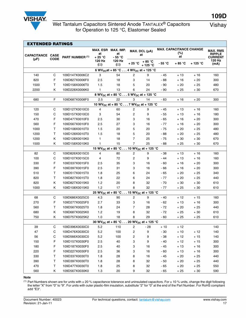
109DWet Tantalum Capacitors Sintered Anode TANTALEX® Capacitors
for Operation to 125 °C, Elastomer Sealed Vishay
EXTENDED RATINGS
CAPACITANCE (µF)
CASE CODE PART NUMBER (1)
MAX. ESRat
+ 25 °C 120 Hz
()
MAX. IMP.at
- 55 °C120 Hz
()
MAX. DCL (µA)at
MAX. CAPACITANCE CHANGE (%)at
MAX. RMSRIPPLE
CURRENT120 Hz (mA)+ 25 °C + 85 °C
+ 125 °C - 55 °C + 85 °C + 125 °C
6 WVDCat + 85 °C . . . 4 WVDC at + 125 °C
140 C 109D147X0006C2 3 54 2 9 - 45 + 13 + 16 160
820 F 109D827X0006F0 2.5 18 3 14 - 88 + 16 + 20 300
1500 T 109D158X0006T0 1.5 18 5 20 - 90 + 20 + 25 480
2200 K 109D228X0006K0 1 13 6 24 - 90 + 25 + 30 670
8 WVDC at + 85 °C . . . 5 WVDC at + 125 °C
680 F 109D687X0008F0 2.5 22 3 14 - 83 + 16 + 20 300
10 WVDC at + 85 °C . . . 7 WVDC at + 125 °C
120 C 109D127X0010C0 4 60 2 9 - 45 + 13 + 16 160
150 C 109D157X0010C0 3 54 2 9 - 55 + 13 + 16 180
470 F 109D477X0010F0 2.5 30 3 16 - 65 + 16 + 20 300
560 F 109D567X0010F0 2.5 27 3 16 - 77 + 16 + 20 300
1000 T 109D108X0010T0 1.5 20 5 20 - 75 + 20 + 25 480
1200 T 109D128X0010T0 1.5 18 5 20 - 88 + 20 + 25 480
1200 K 109D128X0010K0 1 18 7 25 - 75 + 30 + 30 670
1500 K 109D158X0010K0 1 15 7 25 - 88 + 25 + 30 670
15 WVDC at + 85 °C . . . 10 WVDC at + 125 °C
82 C 109D826X0015C0 4 80 2 9 - 38 + 13 + 16 160
100 C 109D107X0015C0 4 72 2 9 - 44 + 13 + 16 160
330 F 109D337X0015F0 2.5 35 3 16 - 60 + 16 + 20 300
390 F 109D397X0015F0 2.5 31 3 16 - 66 + 16 + 20 300
510 T 109D517X0015T0 1.8 25 6 24 - 65 + 20 + 25 340
820 T 109D827X0015T0 1.8 22 6 24 - 77 + 20 + 25 440
820 K 109D827X0015K0 1.2 20 8 32 - 70 + 30 + 30 610
1000 K 109D108X0015K0 1.2 17 8 32 - 77 + 25 + 30 610
25 WVDC at + 85 °C . . . 15 WVDC at + 125 °C
68 C 109D686X0025C0 4.3 90 2 9 - 40 + 12 + 15 160
270 F 109D277X0025F0 2.7 33 3 16 - 62 + 13 + 16 300
560 T 109D567X0025T0 1.8 24 7 28 - 72 + 20 + 25 440
680 K 109D687X0025K0 1.2 19 8 32 - 72 + 25 + 30 610
750 K 109D757X0025K2 1.0 18 8 29 - 60 + 25 + 25 610
30 WVDC at + 85 °C . . . 20 WVDC at + 125 °C
39 C 109D396X0030C0 5.2 110 2 - 28 + 10 + 12 140
47 C 109D476X0030C0 5.2 100 2 9 - 30 + 10 + 12 140
56 C 109D566X0030C0 5.2 100 2 9 - 38 + 12 + 15 140
150 F 109D157X0030F0 2.5 40 3 9 - 40 + 12 + 15 300
180 F 109D187X0030F0 2.5 40 3 16 - 45 + 13 + 16 300
220 F 109D227X0030F0 2.5 36 3 16 - 60 + 13 + 16 300
330 T 109D337X0030T0 1.8 28 8 16 - 45 + 20 + 25 440
390 T 109D397X0030T0 1.8 28 8 32 - 50 + 20 + 25 440
470 T 109D477X0030T0 1.8 25 8 32 - 65 + 20 + 25 550
560 K 109D567X0030K0 1.3 20 9 32 - 65 + 25 + 30 590
Note(1) Part Numbers shown are for units with ± 20 % capacitance tolerance and uninsulated capacitors. For ± 10 % units, change the digit following
the letter “X” from “0” to “9”. For units with outer plastic-film insulation, substitute “2” for “0” at the end of the Part Number. For RoHS compliantadd “E3“.

109DVishay Wet Tantalum Capacitors Sintered Anode TANTALEX® Capacitors
for Operation to 125 °C, Elastomer Sealed
www.vishay.com For technical questions, contact: [email protected] Document Number: 4002318 Revision: 21-Jan-11
50 WVDC at + 85 °C . . . 30 WVDC at + 125 °C
33 C 109D336X0050C0 5 135 2 9 - 29 + 10 + 12 140
120 F 109D127X0050F0 2.5 49 4 24 - 42 + 12 + 15 300
270 T 109D277X0050T0 1.8 29 8 32 - 46 + 20 + 25 440
330 K 109D337X0050K0 1.5 22 9 36 - 46 + 25 + 30 550
60 WVDC at + 85 °C . . . 40 WVDC at + 125 °C
27 C 109D276X0060C0 5 144 3 12 - 24 + 10 + 12 140
68 F 109D686X0060F0 3 60 3 20 - 30 + 12 + 15 270
100 F 109D107X0060F0 2.5 54 4 20 - 36 + 12 + 15 300
140 T 109D147X0060T0 2 32 8 32 - 30 + 16 + 20 420
220 T 109D227X0060T0 1.8 29 8 32 - 40 + 16 + 20 440
270 K 109D277X0060K0 1.5 23 9 36 - 45 + 20 + 25 550
75 WVDC at + 85 °C . . . 50 WVDC at + 125 °C
12 C 109D126X0075C0 5 175 2 12 - 12 + 8 + 10 140
15 C 109D156X0075C0 5 160 2 12 - 14 + 10 + 12 140
22 C 109D226X0075C0 5 157 3 12 - 19 + 10 + 12 140
47 F 109D476X0075F0 3 75 4 24 - 18 + 10 + 12 270
56 F 109D566X0075F0 3 70 4 24 - 20 + 12 + 15 270
82 F 109D826X0075F0 2.5 63 4 24 - 30 + 12 + 15 300
110 T 109D117X0075T0 2 33 9 36 - 25 + 16 + 20 420
180 T 109D187X0075T0 1.8 30 9 36 - 35 + 16 + 20 440
220 K 109D227X0075K0 2.2 24 10 40 - 40 + 20 + 25 450
270 K 109D277X0075K2 1.3 24 10 40 - 40 + 20 + 25 450
100 WVDCat + 85 °C . . . 65 WVDC at + 125 °C
8.2 C 109D825X0100C0 6 250 3 12 - 12 + 12 + 12 130
10 C 109D106X0100C0 6 200 3 12 - 17 + 10 + 12 130
33 F 109D336X0100F0 3.5 85 4 24 - 18 + 15 + 15 250
39 F 109D396X0100F0 3.5 80 5 24 - 20 + 12 + 15 250
56 T 109D566X0100T0 2.2 45 9 36 - 20 + 15 + 15 400
68 T 109D686X0100T0 2.2 40 10 40 - 30 + 14 + 16 400
86 K 109D866X0100K0 3.2 30 10 40 - 25 + 15 + 15 370
125 WVDCat + 85 °C . . . 85 WVDC at + 125 °C
6.8 C 109D685X0125C0 11.7 300 3 12 - 14 + 10 + 12 130
27 F 109D276X0125F0 3.5 90 5 24 - 18 + 12 + 15 250
47 T 109D476X0125T0 2.2 50 10 40 - 26 + 14 + 16 400
56 K 109D566X0125K0 4.1 32 10 40 - 25 + 15 + 15 330
Note(1) Part Numbers shown are for units with ± 20 % capacitance tolerance and uninsulated capacitors. For ± 10 % units, change the digit following
the letter “X” from “0” to “9”. For units with outer plastic-film insulation, substitute “2” for “0” at the end of the Part Number. For RoHS compliantadd “E3“.
EXTENDED RATINGS
CAPACITANCE (µF)
CASE CODE PART NUMBER (1)
MAX. ESRat
+ 25 °C 120 Hz
()
MAX. IMP.at
- 55 °C120 Hz
()
MAX. DCL (µA)at
MAX. CAPACITANCE CHANGE (%)at
MAX. RMSRIPPLE
CURRENT120 Hz (mA)+ 25 °C + 85 °C
+ 125 °C - 55 °C + 85 °C + 125 °C
Document Number: 40025 For technical questions, contact: [email protected] www.vishay.comRevision: 21-Jan-11 19
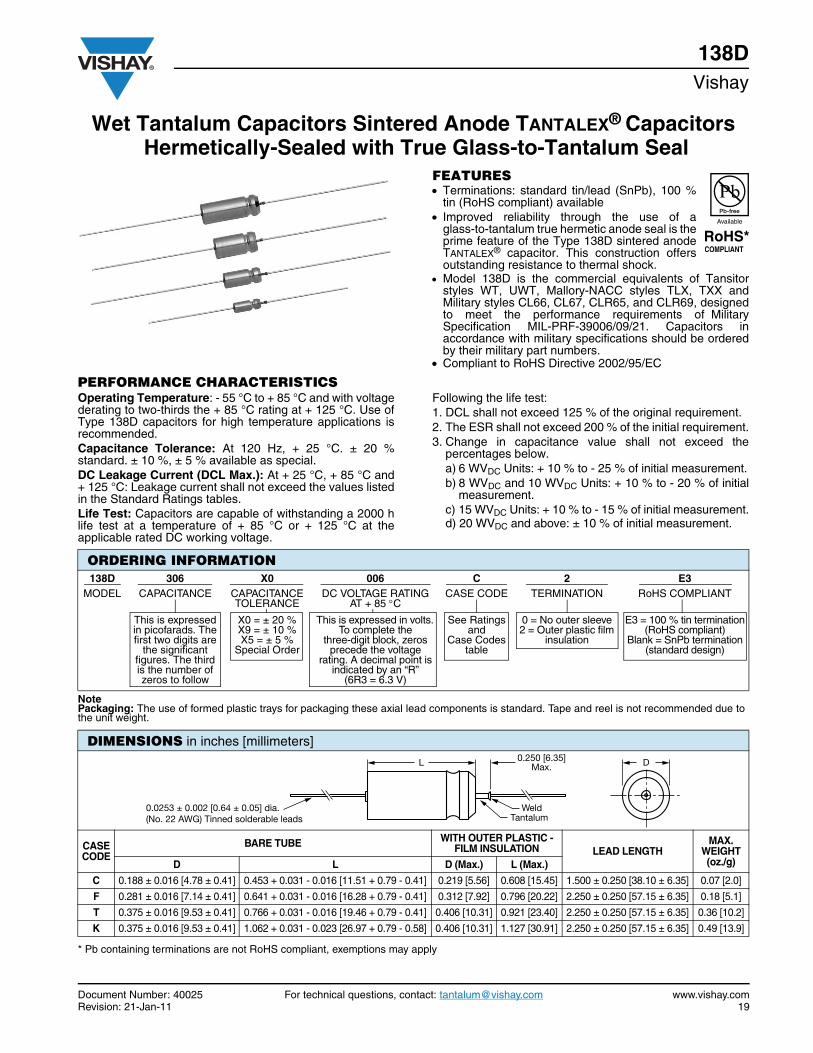
Wet Tantalum Capacitors Sintered Anode TANTALEX® Capacitors Hermetically-Sealed with True Glass-to-Tantalum Seal
138DVishay
FEATURES Terminations: standard tin/lead (SnPb), 100 %
tin (RoHS compliant) available Improved reliability through the use of a
glass-to-tantalum true hermetic anode seal is theprime feature of the Type 138D sintered anodeTANTALEX® capacitor. This construction offersoutstanding resistance to thermal shock.
Model 138D is the commercial equivalents of Tansitorstyles WT, UWT, Mallory-NACC styles TLX, TXX andMilitary styles CL66, CL67, CLR65, and CLR69, designedto meet the performance requirements of MilitarySpecification MIL-PRF-39006/09/21. Capacitors inaccordance with military specifications should be orderedby their military part numbers.
Compliant to RoHS Directive 2002/95/EC
PERFORMANCE CHARACTERISTICSOperating Temperature: - 55 °C to + 85 °C and with voltagederating to two-thirds the + 85 °C rating at + 125 °C. Use ofType 138D capacitors for high temperature applications isrecommended.Capacitance Tolerance: At 120 Hz, + 25 °C. ± 20 %standard. ± 10 %, ± 5 % available as special.DC Leakage Current (DCL Max.): At + 25 °C, + 85 °C and+ 125 °C: Leakage current shall not exceed the values listedin the Standard Ratings tables.Life Test: Capacitors are capable of withstanding a 2000 hlife test at a temperature of + 85 °C or + 125 °C at theapplicable rated DC working voltage.
Following the life test:1. DCL shall not exceed 125 % of the original requirement.2. The ESR shall not exceed 200 % of the initial requirement.3. Change in capacitance value shall not exceed the
percentages below.a) 6 WVDC Units: + 10 % to - 25 % of initial measurement.b) 8 WVDC and 10 WVDC Units: + 10 % to - 20 % of initial
measurement.c) 15 WVDC Units: + 10 % to - 15 % of initial measurement.d) 20 WVDC and above: ± 10 % of initial measurement.
* Pb containing terminations are not RoHS compliant, exemptions may apply
ORDERING INFORMATION138D 306 X0 006 C 2 E3
MODEL CAPACITANCE CAPACITANCE TOLERANCE
DC VOLTAGE RATING AT + 85 C
CASE CODE TERMINATION RoHS COMPLIANT
This is expressed in picofarads. The first two digits are
the significant figures. The third is the number of zeros to follow
X0 = ± 20 % X9 = ± 10 %X5 = ± 5 %
Special Order
This is expressed in volts. To complete the
three-digit block, zeros precede the voltage
rating. A decimal point is indicated by an “R”
(6R3 = 6.3 V)
See Ratingsand
Case Codestable
0 = No outer sleeve 2 = Outer plastic film
insulation
E3 = 100 % tin termination(RoHS compliant)
Blank = SnPb termination(standard design)
Note Packaging: The use of formed plastic trays for packaging these axial lead components is standard. Tape and reel is not recommended due tothe unit weight.
DIMENSIONS in inches [millimeters]
CASECODE
BARE TUBE WITH OUTER PLASTIC - FILM INSULATION LEAD LENGTH
MAX.WEIGHT(oz./g) D L D (Max.) L (Max.)
C 0.188 ± 0.016 [4.78 ± 0.41] 0.453 + 0.031 - 0.016 [11.51 + 0.79 - 0.41] 0.219 [5.56] 0.608 [15.45] 1.500 ± 0.250 [38.10 ± 6.35] 0.07 [2.0]
F 0.281 ± 0.016 [7.14 ± 0.41] 0.641 + 0.031 - 0.016 [16.28 + 0.79 - 0.41] 0.312 [7.92] 0.796 [20.22] 2.250 ± 0.250 [57.15 ± 6.35] 0.18 [5.1]
T 0.375 ± 0.016 [9.53 ± 0.41] 0.766 + 0.031 - 0.016 [19.46 + 0.79 - 0.41] 0.406 [10.31] 0.921 [23.40] 2.250 ± 0.250 [57.15 ± 6.35] 0.36 [10.2]
K 0.375 ± 0.016 [9.53 ± 0.41] 1.062 + 0.031 - 0.023 [26.97 + 0.79 - 0.58] 0.406 [10.31] 1.127 [30.91] 2.250 ± 0.250 [57.15 ± 6.35] 0.49 [13.9]
L
Weld
0.250 [6.35]Max.
0.0253 ± 0.002 [0.64 ± 0.05] dia.(No. 22 AWG) Tinned solderable leads Tantalum
D
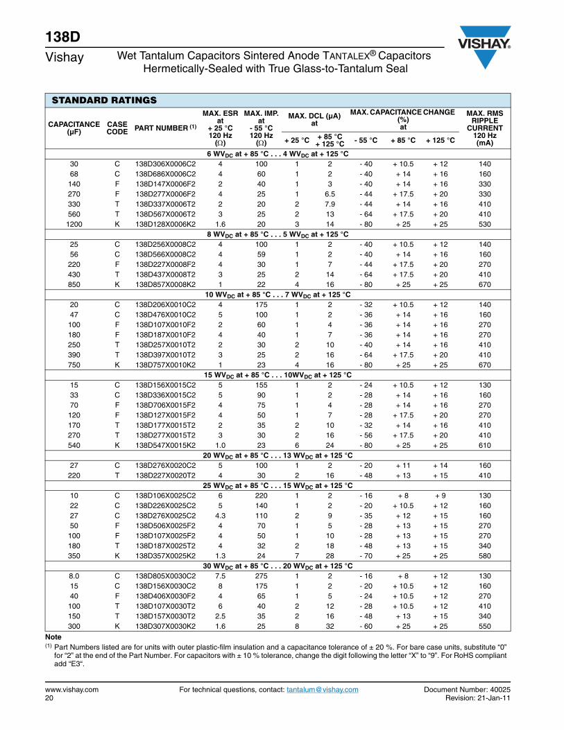
138DVishay Wet Tantalum Capacitors Sintered Anode TANTALEX® Capacitors
Hermetically-Sealed with True Glass-to-Tantalum Seal
www.vishay.com For technical questions, contact: [email protected] Document Number: 4002520 Revision: 21-Jan-11
STANDARD RATINGS
CAPACITANCE (µF)
CASE CODE PART NUMBER (1)
MAX. ESRat
+ 25 °C 120 Hz
()
MAX. IMP.at
- 55 °C120 Hz
()
MAX. DCL (µA)at
MAX. CAPACITANCE CHANGE (%)at
MAX. RMS RIPPLE
CURRENT120 Hz(mA)+ 25 °C + 85 °C
+ 125 °C - 55 °C + 85 °C + 125 °C
6 WVDC at + 85 °C . . . 4 WVDC at + 125 °C 30 C 138D306X0006C2 4 100 1 2 - 40 + 10.5 + 12 14068 C 138D686X0006C2 4 60 1 2 - 40 + 14 + 16 160140 F 138D147X0006F2 2 40 1 3 - 40 + 14 + 16 330270 F 138D277X0006F2 4 25 1 6.5 - 44 + 17.5 + 20 330330 T 138D337X0006T2 2 20 2 7.9 - 44 + 14 + 16 410560 T 138D567X0006T2 3 25 2 13 - 64 + 17.5 + 20 4101200 K 138D128X0006K2 1.6 20 3 14 - 80 + 25 + 25 530
8 WVDC at + 85 °C . . . 5 WVDC at + 125 °C 25 C 138D256X0008C2 4 100 1 2 - 40 + 10.5 + 12 14056 C 138D566X0008C2 4 59 1 2 - 40 + 14 + 16 160220 F 138D227X0008F2 4 30 1 7 - 44 + 17.5 + 20 270430 T 138D437X0008T2 3 25 2 14 - 64 + 17.5 + 20 410850 K 138D857X0008K2 1 22 4 16 - 80 + 25 + 25 670
10 WVDC at + 85 °C . . . 7 WVDC at + 125 °C 20 C 138D206X0010C2 4 175 1 2 - 32 + 10.5 + 12 14047 C 138D476X0010C2 5 100 1 2 - 36 + 14 + 16 160100 F 138D107X0010F2 2 60 1 4 - 36 + 14 + 16 270180 F 138D187X0010F2 4 40 1 7 - 36 + 14 + 16 270250 T 138D257X0010T2 2 30 2 10 - 40 + 14 + 16 410390 T 138D397X0010T2 3 25 2 16 - 64 + 17.5 + 20 410750 K 138D757X0010K2 1 23 4 16 - 80 + 25 + 25 670
15 WVDC at + 85 °C . . . 10WVDC at + 125 °C 15 C 138D156X0015C2 5 155 1 2 - 24 + 10.5 + 12 13033 C 138D336X0015C2 5 90 1 2 - 28 + 14 + 16 16070 F 138D706X0015F2 4 75 1 4 - 28 + 14 + 16 270120 F 138D127X0015F2 4 50 1 7 - 28 + 17.5 + 20 270170 T 138D177X0015T2 2 35 2 10 - 32 + 14 + 16 410270 T 138D277X0015T2 3 30 2 16 - 56 + 17.5 + 20 410540 K 138D547X0015K2 1.0 23 6 24 - 80 + 25 + 25 610
20 WVDC at + 85 °C . . . 13 WVDC at + 125 °C 27 C 138D276X0020C2 5 100 1 2 - 20 + 11 + 14 160220 T 138D227X0020T2 4 30 2 16 - 48 + 13 + 15 410
25 WVDC at + 85 °C . . . 15 WVDC at + 125 °C 10 C 138D106X0025C2 6 220 1 2 - 16 + 8 + 9 13022 C 138D226X0025C2 5 140 1 2 - 20 + 10.5 + 12 16027 C 138D276X0025C2 4.3 110 2 9 - 35 + 12 + 15 16050 F 138D506X0025F2 4 70 1 5 - 28 + 13 + 15 270100 F 138D107X0025F2 4 50 1 10 - 28 + 13 + 15 270180 T 138D187X0025T2 4 32 2 18 - 48 + 13 + 15 340350 K 138D357X0025K2 1.3 24 7 28 - 70 + 25 + 25 580
30 WVDC at + 85 °C . . . 20 WVDC at + 125 °C 8.0 C 138D805X0030C2 7.5 275 1 2 - 16 + 8 + 12 13015 C 138D156X0030C2 8 175 1 2 - 20 + 10.5 + 12 16040 F 138D406X0030F2 4 65 1 5 - 24 + 10.5 + 12 270100 T 138D107X0030T2 6 40 2 12 - 28 + 10.5 + 12 410150 T 138D157X0030T2 2.5 35 2 16 - 48 + 13 + 15 340300 K 138D307X0030K2 1.6 25 8 32 - 60 + 25 + 25 550
Note(1) Part Numbers listed are for units with outer plastic-film insulation and a capacitance tolerance of ± 20 %. For bare case units, substitute “0”
for “2” at the end of the Part Number. For capacitors with ± 10 % tolerance, change the digit following the letter “X” to “9”. For RoHS compliantadd “E3“.

Document Number: 40025 For technical questions, contact: [email protected] www.vishay.comRevision: 21-Jan-11 21
138DWet Tantalum Capacitors Sintered Anode TANTALEX® Capacitors
Hermetically-Sealed with True Glass-to-Tantalum SealVishay
35 WVDC at + 85 °C . . . 22 WVDC at + 125 °C
68 F 138D686X0035F2 6 60 1 8 - 24 + 12 + 15 270
120 T 138D127X0035T2 4 38 2 16 - 30 + 13 + 15 410
270 K 138D277X0035K2 2.2 23 8 32 - 45 + 20 + 25 500
50 WVDC C at + 85 °C . . . 30 WVDC at + 125 °C
5.0 C 138D505X0050C2 9 400 1 2 - 16 + 5 + 6 130
10 C 138D106X0050C2 8 250 1 2 - 24 + 8 + 9 160
25 F 138D256X0050F2 6 95 1 5 - 20 + 10.5 + 12 270
47 F 138D476X0050F2 6 70 1 9 - 28 + 10.5 + 15 270
60 T 138D606X0050T2 3 45 2 12 - 16 + 10.5 + 12 410
82 T 138D826X0050T2 4 45 2 16 - 32 + 13 + 15 410
160 K 138D167X0050K2 2.2 27 8 32 - 50 + 25 + 25 460
60 WVDC at + 85 °C . . . 40 WVDC at + 125 °C
4.0 C 138D405X0060C2 10 550 1 2 - 16 + 5 + 6 110
8.2 C 138D825X0060C2 8 275 1 2 - 24 + 8 + 9 140
20 F 138D206X0060F2 5 105 1 5 - 16 + 10.5 + 12 270
39 F 138D396X0060F2 7 90 1 9 - 28 + 10.5 + 12 330
50 T 138D506X0060T2 4 50 2 12 - 16 + 10.5 + 12 410
68 T 138D686X0060T2 6 50 2 16 - 32 + 10.5 + 12 410
140 K 138D147X0060K2 2.4 28 8 32 - 40 + 20 + 20 430
75 WVDC at + 85 °C . . . 50 WVDC at + 125 °C
3.5 C 138D355X0075C2 10 650 1 2 - 16 + 5 + 6 110
6.8 C 138D685X0075C2 8 300 1 2 - 20 + 8 + 9 140
15 F 138D156X0075F2 6.5 150 1 5 - 16 + 8 + 9 270
33 F 138D336X0075F2 7 90 1 10 - 24 + 10.5 + 15 270
40 T 138D406X0075T2 5 60 2 12 - 16 + 10.5 + 12 410
56 T 138D566X0075T2 6 60 2 17 - 28 + 10.5 + 15 410
110 K 138D117X0075K2 3.1 29 9 36 - 35 + 20 + 20 110
100 WVDC at + 85 °C . . . 65 WVDC at + 125 °C
2.5 C 138D255X0100C2 26.5 950 1 2 - 16 + 7 + 8 100
4.7 C 138D475X0100C2 10 500 1 2 - 16 + 7 + 8 130
11 F 138D116X0100F2 6 200 1 4 - 16 + 7 + 8 230
22 F 138D226X0100F2 7 100 1 9 - 16 + 7 + 8 230
30 T 138D306X0100T2 4 80 2 12 - 16 + 7 + 8 340
43 T 138D436X0100T2 6 70 2 17 - 20 + 7 + 8 340
86 K 138D866X0100K2 3.1 30 9 36 - 25 + 15 + 15 400
125 WVDC at + 85 °C . . . 85 WVDC at + 125 °C
1.7 C 138D175X0125C2 54.6 1250 1 2 - 16 + 7 + 8 100
3.6 C 138D365X0125C2 15 600 1 2 - 16 + 7 + 8 110
9.0 F 138D905X0125F2 15 240 1 5 - 16 + 7 + 8 210
14 F 138D146X0125F2 12 167 1 7 - 16 + 7 + 8 210
18 T 138D186X0125T2 11 129 2 9 - 16 + 7 + 8 340
25 T 138D256X0125T2 10 93 2 13 - 16 + 7 + 8 340
56 K 138D566X0125K2 4.1 32 10 40 - 25 + 15 + 15 400Note(1) Part Numbers listed are for units with outer plastic-film insulation and a capacitance tolerance of ± 20 %. For bare case units, substitute “0”
for “2” at the end of the Part Number. For capacitors with ± 10 % tolerance, change the digit following the letter “X” to “9”. For RoHS compliantadd “E3“.
STANDARD RATINGS
CAPACITANCE (µF)
CASE CODE PART NUMBER (1)
MAX. ESRat
+ 25 °C 120 Hz
()
MAX. IMP.at
- 55 °C120 Hz
()
MAX. DCL (µA)at
MAX. CAPACITANCE CHANGE (%)at
MAX. RMS RIPPLE
CURRENT120 Hz(mA)+ 25 °C + 85 °C
+ 125 °C - 55 °C + 85 °C + 125 °C
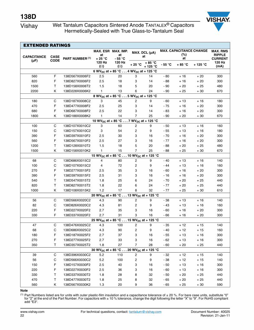
138DVishay Wet Tantalum Capacitors Sintered Anode TANTALEX® Capacitors
Hermetically-Sealed with True Glass-to-Tantalum Seal
www.vishay.com For technical questions, contact: [email protected] Document Number: 4002522 Revision: 21-Jan-11
EXTENDED RATINGS
CAPACITANCE (µF)
CASE CODE PART NUMBER (1)
MAX. ESRat
+ 25 °C 120 Hz
()
MAX. IMP.at
- 55 °C120 Hz
()
MAX. DCL (µA)at
MAX. CAPACITANCE CHANGE (%)at
MAX. RMS RIPPLE
CURRENT120 Hz(mA)+ 25 °C + 85 °C
+ 125 °C - 55 °C + 85 °C + 125 °C
6 WVDC at + 85 °C . . . 4 WVDC at + 125 °C
560 F 138D567X0006F2 2.5 20 3 14 - 80 + 16 + 20 300
820 F 138D827X0006F2 2.5 18 3 14 - 88 + 16 + 20 300
1500 T 138D158X0006T2 1.5 18 5 20 - 90 + 20 + 25 480
2200 K 138D228X0006K2 1 13 6 24 - 90 + 25 + 30 670
8 WVDC at + 85 °C . . . 5 WVDC at + 125 °C
180 C 138D187X0008C2 3 45 2 9 - 60 + 13 + 16 180
470 F 138D477X0008F2 2.5 25 3 14 - 75 + 16 + 20 300
680 F 138D687X0008F2 2.5 22 3 14 - 83 + 16 + 20 300
1800 K 138D188X0008K2 1 14 7 25 - 90 + 20 + 30 670
10 WVDC at + 85 °C . . . 7 WVDC at + 125 °C
100 C 138D107X0010C2 3 60 2 9 - 50 + 13 + 16 160
150 C 138D157X0010C2 3 54 2 9 - 55 + 13 + 16 180
390 F 138D397X0010F2 2.5 30 3 16 - 70 + 16 + 20 300
560 F 138D567X0010F2 2.5 27 3 16 - 77 + 16 + 20 300
1200 T 138D128X0010T2 1.5 18 5 20 - 88 + 20 + 25 480
1500 K 138D158X0010K2 1 15 7 25 - 88 + 25 + 30 670
15 WVDC at + 85 °C . . . 10 WVDC at + 125 °C
68 C 138D686X0015C2 4 80 2 9 - 40 + 13 + 16 140
100 C 138D107X0015C2 4 72 2 9 - 44 + 13 + 16 160
270 F 138D277X0015F2 2.5 35 3 16 - 60 + 16 + 20 300
390 F 138D397X0015F2 2.5 31 3 16 - 16 + 16 + 20 300
540 T 138D547X0015T2 1.8 25 6 24 - 70 + 20 + 25 440
820 T 138D827X0015T2 1.8 22 6 24 - 77 + 20 + 25 440
1000 K 138D108X0015K2 1.2 17 8 32 - 77 + 25 + 30 610
20 WVDC at + 85 °C . . . 13 WVDC at + 125 °C
56 C 138D566X0020C2 4.3 90 2 9 - 38 + 13 + 16 140
82 C 138D826X0020C2 4.3 81 2 9 - 43 + 13 + 16 160
220 F 138D227X0020F2 2.7 35 3 16 - 60 + 16 + 20 300
330 F 138D337X0020F2 2.7 31 3 16 - 66 + 16 + 20 300
25 WVDC at + 85 °C . . . 15 WVDC at + 125 °C
47 C 138D476X0025C2 4.3 100 2 9 - 35 + 12 + 15 140
68 C 138D686X0025C2 4.3 90 2 9 - 40 + 12 + 15 160
180 F 138D187X0025F2 2.7 37 3 16 - 55 + 13 + 16 300
270 F 138D277X0025F2 2.7 33 3 16 - 62 + 13 + 16 300
350 T 138D357X0025T2 1.8 27 7 28 - 60 + 20 + 25 440
30 WVDC at + 85 °C . . . 20 WVDC at + 125 °C
39 C 138D396X0030C2 5.2 110 2 9 - 32 + 12 + 15 140
56 C 138D566X0030C2 5.2 100 2 9 - 38 + 12 + 15 140
150 F 138D157X0030F2 2.5 40 3 16 - 50 + 13 + 16 300
220 F 138D227X0030F2 2.5 36 3 16 - 60 + 13 + 16 300
330 T 138D337X0030T2 1.8 28 8 32 - 50 + 20 + 25 440
470 T 138D477X0030T2 1.8 25 8 32 - 65 + 20 + 25 440
560 K 138D567X0030K2 1.3 20 9 36 - 65 + 25 + 30 590
Note(1) Part Numbers listed are for units with outer plastic-film insulation and a capacitance tolerance of ± 20 %. For bare case units, substitute “0”
for “2” at the end of the Part Number. For capacitors with ± 10 % tolerance, change the digit following the letter “X” to “9”. For RoHS compliantadd “E3“.

Document Number: 40025 For technical questions, contact: [email protected] www.vishay.comRevision: 21-Jan-11 23
138DWet Tantalum Capacitors Sintered Anode TANTALEX® Capacitors
Hermetically-Sealed with True Glass-to-Tantalum SealVishay
35 WVDC at + 85 °C . . . 22 WVDC at + 125 °C
33 C 138D336X0035C2 5.2 130 2 9 - 30 + 10 + 12 140
47 C 138D476X0035C2 5.2 115 2 9 - 35 + 10 + 12 140
120 F 138D127X0035F2 2.5 45 3 16 - 45 + 13 + 16 300
220 T 138D227X0035T2 1.8 30 8 32 - 45 + 20 + 25 440
390 T 138D397X0035T2 1.8 27 8 32 - 58 + 20 + 25 440
470 K 138D477X0035K2 1.3 21 9 36 - 58 + 25 + 30 590
50 WVDC at + 85 °C . . . 30 WVDC at + 125 °C
22 C 138D226X0050C2 5 150 2 9 - 24 + 10 + 12 140
33 C 138D336X0050C2 5 135 2 9 - 29 + 10 + 12 140
82 F 138D826X0050F2 2.5 55 4 24 - 35 + 10 + 15 300
120 F 138D127X0050F2 2.5 49 4 24 - 42 + 12 + 15 300
160 T 138D167X0050T2 1.8 32 6 32 - 35 + 20 + 25 420
270 T 138D277X0050T2 1.8 29 8 32 - 46 + 20 + 25 440
330 K 138D337X0050K2 1.5 22 9 36 - 46 + 25 + 30 550
60 WVDC at + 85 °C . . . 40 WVDC at + 125 °C
18 C 138D186X0060C2 5 160 3 12 - 20 + 10 + 12 140
27 C 138D276X0060C2 5 144 3 12 - 24 + 10 + 12 140
68 F 138D686X0060F2 3 60 4 20 - 30 + 12 + 15 270
100 F 138D107X0060F2 2.5 54 4 20 - 36 + 12 + 15 300
140 T 138D147X0060T2 2 32 8 32 - 30 + 16 + 20 420
220 T 138D227X0060T2 1.8 29 8 32 - 40 + 16 + 20 440
270 K 138D277X0060K2 1.5 23 9 36 - 45 + 20 + 25 550
75 WVDC at + 85 °C . . . 50 WVDC at + 125 °C
15 C 138D156X0075C2 5 175 3 12 - 16 + 10 + 12 140
22 C 138D226X0075C2 5 157 3 12 - 19 + 10 + 12 140
56 F 138D566X0075F2 3 70 4 24 - 25 + 12 + 15 270
82 F 138D826X0075F2 2.5 63 4 24 - 30 + 12 + 15 300
110 T 138D117X0075T2 2 33 9 36 - 25 + 16 + 20 420
180 T 138D187X0075T2 1.8 30 9 36 - 35 + 16 + 20 440
220 K 138D227X0075K2 2.2 24 10 40 - 40 + 20 + 25 450
100 WVDC at + 85 °C . . . 65 v at + 125 °C
8.2 C 138D825X0100C2 6 250 3 12 - 12 + 10 + 12 130
10 C 138D106X0100C2 6 200 3 12 - 17 + 10 + 12 130
33 F 138D336X0100F2 3.5 85 5 24 - 18 + 12 + 15 250
39 F 138D396X0100F2 3.5 80 5 24 - 20 + 12 + 15 250
68 T 138D686X0100T2 2.2 40 10 40 - 30 + 14 + 16 400
120 K 138D127X0100K2 2.8 30 12 48 - 35 + 15 + 17 440
125 WVDC at + 85 °C . . . 85 WVDC at + 125 °C
6.8 C 138D685X0125C2 11.7 300 3 12 - 14 + 10 + 12 130
27 F 138D276X0125F2 3.5 90 5 24 - 18 + 12 + 15 250
39 T 138D396X0125T2 2.2 60 10 40 - 16 + 14 + 16 400
47 T 138D476X0125T2 2.2 50 10 40 - 26 + 14 + 16 400
82 K 138D826X0125K2 2.8 32 12 48 - 30 + 15 + 17 440
Note(1) Part Numbers listed are for units with outer plastic-film insulation and a capacitance tolerance of ± 20 %. For bare case units, substitute “0”
for “2” at the end of the Part Number. For capacitors with ± 10 % tolerance, change the digit following the letter “X” to “9”. For RoHS compliantadd “E3“.
EXTENDED RATINGS
CAPACITANCE (µF)
CASE CODE PART NUMBER (1)
MAX. ESRat
+ 25 °C 120 Hz
()
MAX. IMP.at
- 55 °C120 Hz
()
MAX. DCL (µA)at
MAX. CAPACITANCE CHANGE (%)at
MAX. RMS RIPPLE
CURRENT120 Hz(mA)+ 25 °C + 85 °C
+ 125 °C - 55 °C + 85 °C + 125 °C
138DVishay Wet Tantalum Capacitors Sintered Anode TANTALEX® Capacitors
Hermetically-Sealed with True Glass-to-Tantalum Seal
www.vishay.com For technical questions, contact: [email protected] Document Number: 4002524 Revision: 21-Jan-11
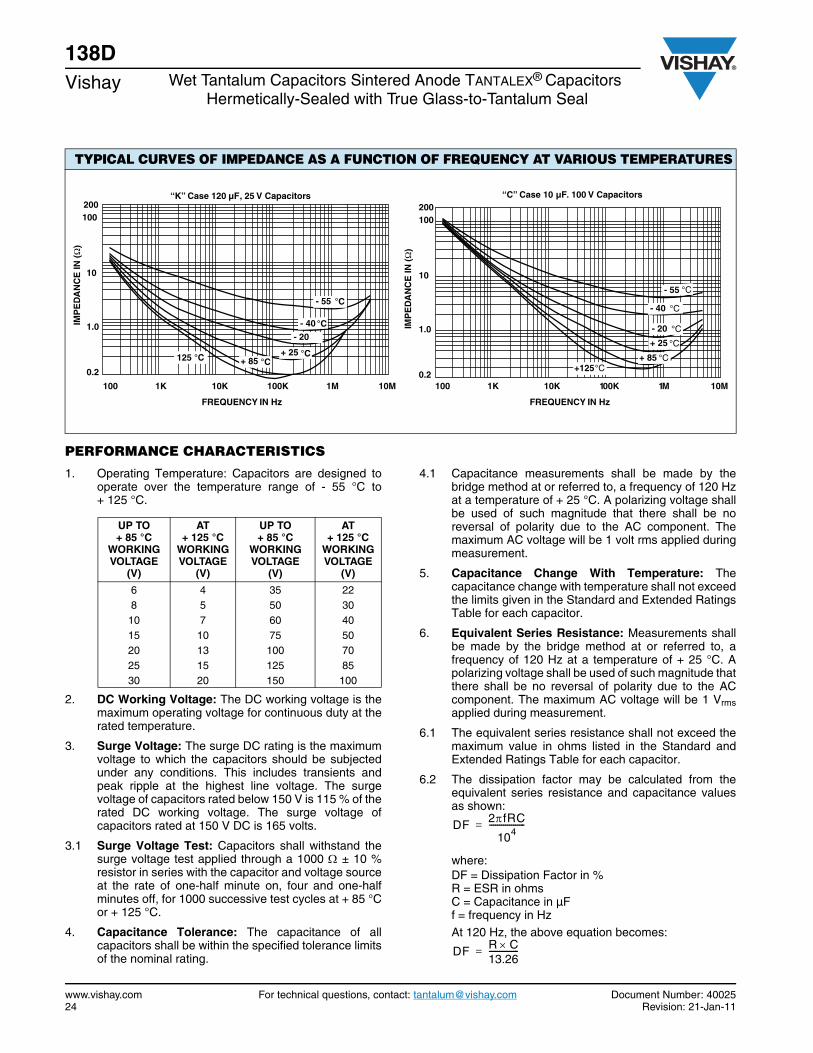
PERFORMANCE CHARACTERISTICS
1. Operating Temperature: Capacitors are designed tooperate over the temperature range of - 55 °C to+ 125 °C.
2. DC Working Voltage: The DC working voltage is themaximum operating voltage for continuous duty at therated temperature.
3. Surge Voltage: The surge DC rating is the maximumvoltage to which the capacitors should be subjectedunder any conditions. This includes transients andpeak ripple at the highest line voltage. The surgevoltage of capacitors rated below 150 V is 115 % of therated DC working voltage. The surge voltage ofcapacitors rated at 150 V DC is 165 volts.
3.1 Surge Voltage Test: Capacitors shall withstand thesurge voltage test applied through a 1000 ± 10 %resistor in series with the capacitor and voltage sourceat the rate of one-half minute on, four and one-halfminutes off, for 1000 successive test cycles at + 85 °Cor + 125 °C.
4. Capacitance Tolerance: The capacitance of allcapacitors shall be within the specified tolerance limitsof the nominal rating.
4.1 Capacitance measurements shall be made by thebridge method at or referred to, a frequency of 120 Hzat a temperature of + 25 °C. A polarizing voltage shallbe used of such magnitude that there shall be noreversal of polarity due to the AC component. Themaximum AC voltage will be 1 volt rms applied duringmeasurement.
5. Capacitance Change With Temperature: Thecapacitance change with temperature shall not exceedthe limits given in the Standard and Extended RatingsTable for each capacitor.
6. Equivalent Series Resistance: Measurements shallbe made by the bridge method at or referred to, afrequency of 120 Hz at a temperature of + 25 °C. Apolarizing voltage shall be used of such magnitude thatthere shall be no reversal of polarity due to the ACcomponent. The maximum AC voltage will be 1 Vrmsapplied during measurement.
6.1 The equivalent series resistance shall not exceed themaximum value in ohms listed in the Standard andExtended Ratings Table for each capacitor.
6.2 The dissipation factor may be calculated from theequivalent series resistance and capacitance valuesas shown:
where:DF = Dissipation Factor in %R = ESR in ohmsC = Capacitance in µFf = frequency in HzAt 120 Hz, the above equation becomes:
TYPICAL CURVES OF IMPEDANCE AS A FUNCTION OF FREQUENCY AT VARIOUS TEMPERATURES
- 55
- 40
- 20
+ 25+ 85
IMP
ED
AN
CE
IN (
)
0.2
1.0
10
100 200
FREQUENCY IN Hz
100 1K 10K 100K 1M 10M
“K” Case 120 µF, 25 V Capacitors
°C
°C
°C°C125 °C
- 55
- 40
- 20
+ 25
+ 85+125
FREQUENCY IN HzIM
PE
DA
NC
E IN
(
)
100 1K 10K 100K 1M 10M0.2
1.0
10
100200
“C” Case 10 µF. 100 V Capacitors
°C
°C
°C
°C
°C°C
UP TO + 85 °C
WORKING VOLTAGE
(V)
AT + 125 °C
WORKING VOLTAGE
(V)
UP TO + 85 °C
WORKING VOLTAGE
(V)
AT + 125 °C
WORKING VOLTAGE
(V)
6 4 35 22 8 5 50 30 10 7 60 40 15 10 75 50 20 13 100 70 25 15 125 85 30 20 150 100
DF 2fRC
104------------------=
DF R C13.26---------------=
Document Number: 40025 For technical questions, contact: [email protected] www.vishay.comRevision: 21-Jan-11 25
138DWet Tantalum Capacitors Sintered Anode TANTALEX® Capacitors
Hermetically-Sealed with True Glass-to-Tantalum SealVishay
PERFORMANCE CHARACTERISTICS (Continued)For example, percent dissipation factor of a 30 µF, 6 Vcapacitor, which has a maximum ESR of 3.4 at+ 25 °C and 120 Hz, would be calculated as shown:
7. Leakage Current: Measurements shall be made atthe applicable rated working voltage at + 25 °C ± 5 °Cthrough application of a steady source of power, suchas a regulated power supply. The total resistance inseries with each capacitor shall be between 1000 and 10 000 . The voltage shall be applied to thecapacitor for 5 minutes before making the leakagecurrent measurement.
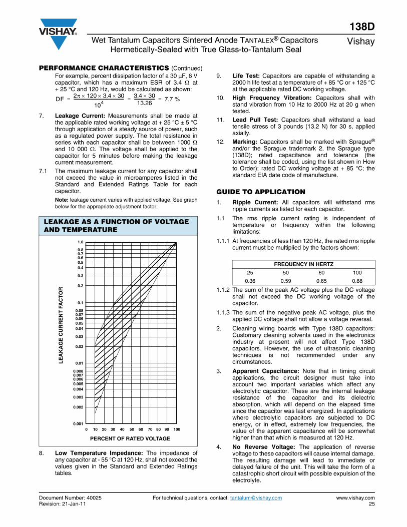
7.1 The maximum leakage current for any capacitor shallnot exceed the value in microamperes listed in theStandard and Extended Ratings Table for eachcapacitor.Note: leakage current varies with applied voltage. See graphbelow for the appropriate adjustment factor.
8. Low Temperature Impedance: The impedance ofany capacitor at - 55 °C at 120 Hz, shall not exceed thevalues given in the Standard and Extended Ratingstables.
9. Life Test: Capacitors are capable of withstanding a2000 h life test at a temperature of + 85 °C or + 125 °Cat the applicable rated DC working voltage.
10. High Frequency Vibration: Capacitors shall withstand vibration from 10 Hz to 2000 Hz at 20 g whentested.
11. Lead Pull Test: Capacitors shall withstand a leadtensile stress of 3 pounds (13.2 N) for 30 s, appliedaxially.
12. Marking: Capacitors shall be marked with Sprague®
and/or the Sprague trademark 2, the Sprague type(138D); rated capacitance and tolerance (thetolerance shall be coded, using the list shown in Howto Order); rated DC working voltage at + 85 °C; thestandard EIA date code of manufacture.
GUIDE TO APPLICATION1. Ripple Current: All capacitors will withstand rms
ripple currents as listed for each capacitor.
1.1 The rms ripple current rating is independent oftemperature or frequency within the followinglimitations:
1.1.1 At frequencies of less than 120 Hz, the rated rms ripplecurrent must be multiplied by the factors shown:
1.1.2 The sum of the peak AC voltage plus the DC voltageshall not exceed the DC working voltage of thecapacitor.
1.1.3 The sum of the negative peak AC voltage, plus theapplied DC voltage shall not allow a voltage reversal.
2. Cleaning wiring boards with Type 138D capacitors:Customary cleaning solvents used in the electronicsindustry at present will not affect Type 138Dcapacitors. However, the use of ultrasonic cleaningtechniques is not recommended under anycircumstances.
3. Apparent Capacitance: Note that in timing circuitapplications, the circuit designer must take intoaccount two important variables which affect anyelectrolytic capacitor. These are the internal leakageresistance of the capacitor and its dielectricabsorption, which will depend on the elapsed timesince the capacitor was last energized. In applicationswhere electrolytic capacitors are subjected to DCenergy, or in effect, extremely low frequencies, thevalue of the apparent capacitance will be somewhathigher than that which is measured at 120 Hz.
4. No Reverse Voltage: The application of reversevoltage to these capacitors will cause internal damage.The resulting damage will lead to immediate ordelayed failure of the unit. This will take the form of acatastrophic short circuit with possible expulsion of theelectrolyte.
LEAKAGE AS A FUNCTION OF VOLTAGE AND TEMPERATURE
DF 2 120 3.4 30
104-------------------------------------------------- 3.4 30
13.26--------------------- 7.7 %= = =
1.0
0.80.70.60.50.4
0.3
0.2
0.1
0.080.070.060.050.04
0.03
0.02
0.01
0.0080.0070.0060.0050.004
0.003
0.002
0.001
LE
AK
AG
E C
UR
RE
NT
FA
CTO
R
0
PERCENT OF RATED VOLTAGE
10 3020 9040 50 60 70 80 100
FREQUENCY IN HERTZ
25 50 60 100
0.36 0.59 0.65 0.88

738D, CT9 (CECC 30202-004)www.vishay.com Vishay
Revision: 08-Jan-10 26 Document Number: 40054
For technical questions, contact: [email protected] DOCUMENT IS SUBJECT TO CHANGE WITHOUT NOTICE. THE PRODUCTS DESCRIBED HEREIN AND THIS DOCUMENT
ARE SUBJECT TO SPECIFIC DISCLAIMERS, SET FORTH AT www.vishay.com/doc?91000
Wet Tantalum Capacitors with Glass-to-Tantalum Hermetic Seal,Sintered Anode TANTALEX® Capacitors
FEATURES• Terminations: standard tin/lead (SnPb),
100 % tin (RoHS compliant) availableImproved reliability through the use of aglass-to-tantalum true hermetic anode seal isthe prime feature of the type 138D sinteredanode
• Hermetic glass-to-tantalum seal• High CV per unit volume• Extremely low leakage current• Wide temperature range: - 55 °C to + 175 °C• Improved reliability through the use of a glass-to- tantalum
true hermetic anode seal is the prime feature of the 738Dand CT9 sintered anode TANTALEX® capacitor. Thisconstruction eliminates all internal lead welds whileretaining the strength of internal lead-welded parts.
• The construction offers outstanding resistance to thermalshock
• Compliant to RoHS Directive 2002/95/ECNote
* Pb containing terminations are not RoHS compliant, exemptionsmay apply
PERFORMANCE CHARACTERISTICSOperating Temperature: - 55 °C to + 85 °C and withvoltage derating to two-thirds the + 85 °C rating at + 125 °C.Capable of + 175 °C operation at reduced voltage. Use ofType 135D capacitors for high temperature applications isrecommended.
Capacitance Tolerance: At 120 Hz, + 25 °C. ± 20 %standard. ± 10 %, ± 5 % available as special.
DC Leakage Current (DCL Max.): At + 25 °C, + 85 °C and+ 125 °C: Leakage current shall not exceed the values listedin the Standard Ratings tables.
Life Test: Capacitors are capable of withstanding a 2000 hlife test at a temperature of + 85 °C or + 125 °C at theapplicable rated DC working voltage.
APPROVALSCECC 30202-004 CT9 style
Note• Packaging: The use of formed plastic trays for packaging these axial lead components is standard. Tape and reel is not recommended due
to the unit weight
ORDERING INFORMATIONCT9738D 226 X0 100 B 2 E3
MODEL CAPACITANCE CAPACITANCETOLERANCE
DC VOLTAGE RATINGAT + 85 °C
CASECODE
STYLE NUMBER RoHS COMPLIANT
This is expressedin picofarads. Thefirst two digits are
the significantfigures. The thirdis the number ofzeros to follow
X0 = ± 20 %X9 = ± 10 %X5 = ± 5 %
Special Order
This is expressed involts. To complete thethree-digit block, zeros
precede the voltagerating. A decimal point is
indicated by an “R”(6R3 = 6.3 V)
SeeRatings
andCase
Codestable
0 = Bare case2 = Outer polyester
film insulation6 = High temperature
film insulation(above + 125 °C)
E3 = 100 % tin termination(RoHS compliant design)Blank = SnPb termination
(standard design)

738D, CT9 (CECC 30202-004)www.vishay.com Vishay
Revision: 08-Jan-10 27 Document Number: 40054
For technical questions, contact: [email protected] DOCUMENT IS SUBJECT TO CHANGE WITHOUT NOTICE. THE PRODUCTS DESCRIBED HEREIN AND THIS DOCUMENT
ARE SUBJECT TO SPECIFIC DISCLAIMERS, SET FORTH AT www.vishay.com/doc?91000
DIMENSIONS in inches [millimeters]
CASECODE
BARE TUBE WITH OUTERPLASTIC - FILM INSULATION LEAD LENGTH MAX. WEIGHT
(oz./g) D L D (Max.) L (Max.)
A 0.188 ± 0.016[4.78 ± 0.41]
0.453 + 0.031/- 0.016[11.51 + 0.79/- 0.41]
0.219[5.56]
0.608[15.45]
1.500 ± 0.250[38.10 ± 6.35]
0.07[2.0]
B 0.281 ± 0.016[7.14 ± 0.41]
0.641 + 0.031/- 0.016[16.28 + 0.79/- 0.41]
0.312[7.92]
0.796[20.22]
2.250 ± 0.250[57.15 ± 6.35]
0.18[5.1]
C 0.375 ± 0.016[9.53 ± 0.41]
0.766 + 0.031/- 0.016[19.46 + 0.79/- 0.41]
0.406[10.31]
0.921[23.40]
2.250 ± 0.250[57.15 ± 6.35]
0.36[10.2]
D 0.375 ± 0.016[9.53 ± 0.41]
1.062 + 0.031/- 0.023[26.97 + 0.79/- 0.58]
0.406[10.31]
1.127[30.91]
2.250 ± 0.250[57.15 ± 6.35]
0.49[13.9]
738D STANDARD RATINGS
CAPACITANCE (μF)
CASECODE PART NUMBER
MAX.DFAT
+ 20 °C(%)
MAX.IMP.
AT - 55 °C100 Hz
()
MAX.IMP.
AT + 20°C100 kHz
()
MAX. DCL (μA) AT
MAX. CAPACITANCECHANGE (%) AT
+ 20 °C + 85 °C+ 125 °C - 55 °C + 85 °C + 125 °C
6.3 VDC AT + 85 °C; 4 VDC AT + 125 °C; 3 VDC AT + 175 °C 68 A 738D686X06R3A2 17.1 10 1.0 1 2 - 40 + 10.5 + 17.5 270 B 738D277X06R3B2 67.8 10 1.0 1 7 - 44 + 17.5 + 20 560 C 738D567X06R3C2 151.9 10 1.0 2 13 - 64 + 17.5 + 20 1000 D 738D108X06R3D2 100.5 10 1.0 3 14 - 80 + 25 + 25 1200 D 738D128X06R3D2 120.6 10 1.0 3 14 - 80 + 25 + 25
8 VDC AT + 85 °C; 5 VDC AT + 125 °C; 4 VDC AT + 175 °C 56 A 738D566X0008A2 14.1 10 1.0 1 2 - 40 + 10.5 + 16 220 B 738D227X0008B2 55.2 10 1.0 1 7 - 44 + 17.5 + 20 470 C 738D477X0008C2 82.6 10 1.0 2 14 - 64 + 17.5 + 20 820 D 738D827X0008D2 51.5 10 1.0 4 16 - 80 + 25 + 25
10 VDC AT + 85 °C; 6.3 VDC AT + 125 °C; 5 VDC AT + 175 °C 39 A 738D396X0010A2 15.1 10 1.0 1 2 - 36 + 12 + 16 47 A 738D476X0010A2 15.1 10 1.0 1 2 - 36 + 14 + 16 150 B 738D157X0010B2 28.2 10 1.0 1 6 - 36 + 14 + 16 180 B 738D187X0010B2 45.2 10 1.0 1 7 - 36 + 14 + 16 330 C 738D337X0010C2 51.9 10 1.0 2 16 - 60 + 17.5 + 20 390 C 738D397X0010C2 73.5 10 1.0 2 16 - 64 + 17.5 + 20 680 D 738D687X0010D2 42.7 10 1.0 4 16 - 80 + 25 + 25
16 VDC AT + 85 °C; 10 VDC AT + 125 °C; 8 VDC AT + 175 °C 27 A 738D276X0016A2 10.3 10 1.0 1 2 - 28 + 10.5 + 16 33 A 738D336X0016A2 10.3 10 1.0 1 2 - 28 + 14 + 16 120 B 738D127X0016B2 30.2 10 1.0 1 7 - 28 + 17.5 + 20 220 C 738D227X0016C2 34.5 10 1.0 2 16 - 50 + 17.5 + 18 270 C 738D277X0016C2 50.8 10 1.0 2 16 - 56 + 17.5 + 20 470 D 738D477X0016D2 35.4 10 1.0 6 24 - 80 + 25 + 25 560 D 738D567X0016D2 42.2 10 1.0 6 24 - 80 + 25 + 25
25 VDC AT + 85 °C; 16 VDC AT + 125 °C; 13 VDC AT + 175 °C 18 A 738D186X0025A2 6.9 10 1.0 1 2 - 20 + 10.5 + 12 22 A 738D226X0025A2 6.9 10 1.0 1 2 - 20 + 10.5 + 12 82 B 738D826X0025B2 20.6 10 1.0 1 10 - 28 + 13 + 15 100 B 738D107X0025B2 25.1 10 1.0 1 10 - 28 + 13 + 15 180 C 738D187X0025C2 42.2 10 1.0 2 18 - 48 + 13 + 15 330 D 738D337X0025D2 27.2 10 1.0 7 28 - 70 + 25 + 25 390 D 738D397X0025D2 31.8 10 1.0 7 28 - 70 + 25 + 25
L
Weld
0.250 [6.35]Max.
0.0253 ± 0.002 [0.64 ± 0.05] dia.(No. 22 AWG) Tinned solderable leads Tantalum
D
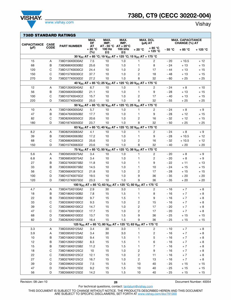
738D, CT9 (CECC 30202-004)www.vishay.com Vishay
Revision: 08-Jan-10 28 Document Number: 40054
For technical questions, contact: [email protected] DOCUMENT IS SUBJECT TO CHANGE WITHOUT NOTICE. THE PRODUCTS DESCRIBED HEREIN AND THIS DOCUMENT
ARE SUBJECT TO SPECIFIC DISCLAIMERS, SET FORTH AT www.vishay.com/doc?91000
30 VDC AT + 85 °C; 19 VDC AT + 125 °C; 15 VDC AT + 175 °C
15 A 738D156X0030A2 7.5 10 1.0 1 2 - 20 + 10.5 + 12 68 B 738D686X0030B2 25.6 10 1.0 1 8 - 24 + 13 + 15 120 C 738D127X0030C2 24.4 10 1.0 2 17 - 44 + 13 + 15 150 C 738D157X0030C2 37.7 10 1.0 2 18 - 48 + 13 + 15 270 D 738D277X0030D2 27.2 10 1.0 8 32 - 60 + 25 + 25
40 VDC AT + 85 °C; 25 VDC AT + 125 °C; 20 VDC AT + 175 °C
12 A 738D126X0040A2 6.7 10 1.0 1 2 - 24 + 8 + 10 56 B 738D566X0040B2 21.1 10 1.0 1 9 - 28 + 13 + 15 100 C 738D107X0040C2 15.7 10 1.0 2 17 - 40 + 13 + 15 220 D 738D227X0040D2 25.0 10 1.0 8 32 - 55 + 25 + 25
50 VDC AT + 85 °C; 32 VDC AT + 125 °C; 25 VDC AT + 175 °C
10 A 738D106X0050A2 5.7 10 1.0 1 2 - 24 + 8 + 9 47 B 738D476X0050B2 17.7 10 1.0 1 9 - 28 + 12 + 15 82 C 738D826X0050C2 20.6 10 1.0 2 16 - 32 + 12 + 15 180 D 738D187X0050D2 23.7 10 1.0 8 32 - 50 + 25 + 25
63 VDC AT + 85 °C; 40 VDC AT + 125 °C; 32 VDC AT + 175 °C
8.2 A 738D825X0063A2 4.1 10 1.0 1 2 - 24 + 8 + 9 39 B 738D396X0063B2 17.2 10 1.0 1 9 - 28 + 10.5 + 12 68 C 738D686X0063C2 25.6 10 1.0 2 16 - 32 + 10.5 + 12 150 D 738D157X0063D2 23.6 10 1.0 8 32 - 40 + 20 + 20
75 VDC AT + 85 °C; 50 VDC AT + 125 °C; 38 VDC AT + 175 °C
5.6 A 738D565X0075A2 3.4 10 1.0 1 2 - 20 + 8 + 9 6.8 A 738D685X0075A2 3.4 10 1.0 1 2 - 20 + 8 + 9 27 B 738D276X0075B2 11.8 10 1.0 1 9 - 22 + 11 + 13 33 B 738D336X0075B2 14.5 10 1.0 1 10 - 24 + 15 + 15 56 C 738D566X0075C2 21.8 10 1.0 2 17 - 28 + 15 + 15 100 D 738D107X0075D2 19.5 10 1.0 9 36 - 35 + 20 + 20 120 D 738D127X0075D2 23.3 10 1.0 9 36 - 35 + 20 + 20
100 VDC AT + 85 °C; 63 VDC AT + 125 °C; 50 VDC AT + 175 °C
4.7 A 738D475X0100A2 2.9 30 3.0 1 2 - 16 + 7 + 8 18 B 738D186X0100B2 7.8 15 1.5 1 8 - 16 + 7 + 8 22 B 738D226X0100B2 9.7 15 1.5 1 9 - 16 + 7 + 8 33 C 738D336X0100C2 9.3 15 1.0 2 15 - 16 + 7 + 8 39 C 738D396X0100C2 14.7 15 1.0 2 17 - 20 + 7 + 8 47 C 738D476X0100C2 17.7 15 1.0 2 17 - 20 + 7 + 8 68 D 738D686X0100D2 13.7 15 1.5 9 36 - 25 + 15 + 15 82 D 738D826X0100D2 16.4 15 1.5 9 36 - 25 + 15 + 15
125 VDC AT + 85 °C; 80 VDC AT + 125 °C; 63 VDC AT + 175 °C
3.3 A 738D335X0125A2 3.4 30 3.0 1 2 - 10 + 7 + 8 3.9 A 738D395X0125A2 3.4 30 3.0 1 2 - 16 + 7 + 8 10 B 738D106X0125B2 9.4 15 1.5 1 5 - 16 + 7 + 8 12 B 738D126X0125B2 8.3 15 1.5 1 6 - 16 + 7 + 8 15 B 738D156X0125B2 11.2 15 1.5 1 7 - 16 + 7 + 8 18 C 738D186X0125C2 10 15 1.0 2 9 - 16 + 7 + 8 22 C 738D226X0125C2 12.1 15 1.0 2 11 - 16 + 7 + 8 27 C 738D276X0125C2 16.7 15 1.0 2 13 - 16 + 7 + 8 39 D 738D396X0125D2 7.5 15 1.5 10 40 - 25 + 15 + 15 47 D 738D476X0125D2 9.2 15 1.5 10 40 - 25 + 15 + 15 56 D 738D566X0125D2 14.2 15 1.5 10 40 - 25 + 15 + 15
738D STANDARD RATINGS
CAPACITANCE (μF)
CASECODE PART NUMBER
MAX.DFAT
+ 20 °C(%)
MAX.IMP.
AT - 55 °C100 Hz
()
MAX.IMP.
AT + 20°C100 kHz
()
MAX. DCL (μA) AT
MAX. CAPACITANCECHANGE (%) AT
+ 20 °C + 85 °C+ 125 °C - 55 °C + 85 °C + 125 °C
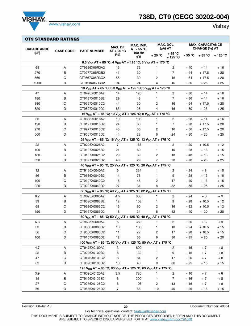
738D, CT9 (CECC 30202-004)www.vishay.com Vishay
Revision: 08-Jan-10 29 Document Number: 40054
For technical questions, contact: [email protected] DOCUMENT IS SUBJECT TO CHANGE WITHOUT NOTICE. THE PRODUCTS DESCRIBED HEREIN AND THIS DOCUMENT
ARE SUBJECT TO SPECIFIC DISCLAIMERS, SET FORTH AT www.vishay.com/doc?91000
CT9 STANDARD RATINGS
CAPACITANCE (μF) CASE CODE PART NUMBER
MAX. DFAT + 20 °C
(%)
MAX. IMP.AT - 55 °C
100 Hz()
MAX. DCL(μA) AT
MAX. CAPACITANCECHANGE (%) AT
+ 20 °C + 85 °C+ 125 °C - 55 °C + 85 °C + 125 °C
6.3 VDC AT + 85 °C; 4 VDC AT + 125 °C; 3 VDC AT + 175 °C
68 A CT9686X06R3A2 15 72 1 2 - 40 + 14 + 16
270 B CT9277X06R3B2 41 30 1 7 - 44 + 17.5 + 20
560 C CT9567X06R3C2 55 30 2 16 - 64 + 17.5 + 20
1200 D CT9128X06R3D2 94 24 4 16 - 80 + 25 + 25
10 VDC AT + 85 °C; 6.3 VDC AT + 125 °C; 5 VDC AT + 175 °C
47 A CT9476X0010A2 14 120 1 2 - 36 + 14 + 16
180 B CT9187X0010B2 29 48 1 7 - 36 + 14 + 16
390 C CT9397X0010C2 44 30 2 16 - 64 + 17.5 + 20
820 D CT9827X0010D2 65 28 4 16 - 80 + 25 + 25
16 VDC AT + 85 °C; 10 VDC AT + 125 °C; 8 VDC AT + 175 °C
33 A CT9336X0016A2 10 108 1 2 - 28 + 14 + 16
120 B CT9127X0016B2 24 60 1 7 - 28 + 17.5 + 20
270 C CT9277X0016C2 45 36 2 16 - 56 + 17.5 + 20
560 D CT9567X0016D2 44 28 6 24 - 80 + 25 + 25
25 VDC AT + 85 °C; 16 VDC AT + 125 °C; 13 VDC AT + 175 °C
22 A CT9226X0025A2 7 168 1 2 - 20 + 10.5 + 12
100 B CT9107X0025B2 21 60 1 10 - 28 + 13 + 15
180 C CT9187X0025C2 29 39 2 18 - 48 + 13 + 15
390 D CT9397X0025D2 40 29 7 28 - 70 + 25 + 25
40 VDC AT + 85 °C; 25 VDC AT + 125 °C; 20 VDC AT + 175 °C
12 A CT9126X0040A2 6 234 1 2 - 24 + 8 + 10
56 B CT9566X0040B2 14 78 1 9 - 28 + 13 + 15
100 C CT9107X0040C2 18 48 2 17 - 40 + 13 + 15
220 D CT9227X0040D2 27 31 8 32 - 55 + 25 + 25
63 VDC AT + 85 °C; 40 VDC AT + 125 °C; 32 VDC AT + 175 °C
8.2 A CT9825X0063A2 4.5 330 1 2 - 24 + 8 + 9
39 B CT9396X0063B2 12 108 1 9 - 28 + 10.5 + 12
68 C CT9686X0063C2 13 60 2 16 - 32 + 10.5 + 12
150 D CT9157X0063D2 18 34 8 32 - 40 + 20 + 20
80 VDC AT + 85 °C; 50 VDC AT + 125 °C; 40 VDC AT + 175 °C
6.8 A CT9685X0080A2 5 360 1 2 - 20 + 8 + 9
33 B CT9336X0080B2 10 108 1 10 - 24 + 10.5 + 15
56 C CT9566X0080C2 11 72 2 17 - 28 + 10.5 + 15
100 D CT9107X0080D2 12 36 9 36 - 35 + 20 + 20
100 VDC AT + 85 °C; 63 VDC AT + 125 °C; 50 VDC AT + 175 °C
4.7 A CT9475X0100A2 3 600 1 2 - 16 + 7 + 8
22 B CT9226X0100B2 8 132 1 9 - 16 + 7 + 8
47 C CT9476X0100C2 8 84 2 17 - 20 + 7 + 8
82 D CT9826X0100D2 10 40 9 36 - 25 + 15 + 15
125 VDC AT + 85 °C; 80 VDC AT + 125 °C; 63 VDC AT + 175 °C
3.9 A CT9395X0125A2 3.5 720 1 2 - 16 + 7 + 8
15 B CT9156X0125B2 6 200 1 7 - 16 + 7 + 8
27 C CT9276X0125C2 6 106 2 13 - 16 + 7 + 8
56 D CT9566X0125D2 7 58 10 40 - 25 + 15 + 15
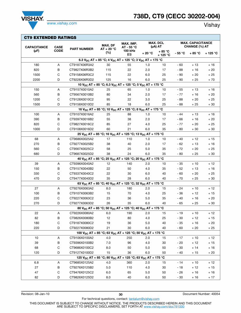
738D, CT9 (CECC 30202-004)www.vishay.com Vishay
Revision: 08-Jan-10 30 Document Number: 40054
For technical questions, contact: [email protected] DOCUMENT IS SUBJECT TO CHANGE WITHOUT NOTICE. THE PRODUCTS DESCRIBED HEREIN AND THIS DOCUMENT
ARE SUBJECT TO SPECIFIC DISCLAIMERS, SET FORTH AT www.vishay.com/doc?91000
CT9 EXTENDED RATINGS
CAPACITANCE (μF)
CASECODE PART NUMBER
MAX. DFAT + 20 °C
(%)
MAX. IMP.AT - 55 °C100 kHz
()
MAX. DCL (μA) AT
MAX. CAPACITANCECHANGE (%) AT
+ 20 °C + 85 °C+ 125 °C - 55 °C + 85 °C + 125 °C
6.3 VDC AT + 85 °C; 4 VDC AT + 125 °C; 3 VDC AT + 175 °C
180 A CT9187X06R3A2 30 55 1.0 10 - 60 + 13 + 16
820 B CT9827X06R3B2 115 22 2.0 17 - 88 + 16 + 20
1500 C CT9158X06R3C2 115 22 6.0 25 - 90 + 20 + 25
2200 D CT9228X06R3D2 125 16 6.0 25 - 90 + 25 + 70
10 VDC AT + 85 °C; 6.3 VDC AT + 125 °C; 5 VDC AT + 175 °C
150 A CT9157X0010A2 25 65 1.0 10 - 55 + 13 + 16
560 B CT9567X0010B2 80 34 2.0 17 - 77 + 16 + 20
1200 C CT9128X0010C2 95 22 3.0 25 - 88 + 20 + 25
1500 D CT9158X0010D2 85 18 6.0 25 - 88 + 25 + 30
16 VDC AT + 85 °C; 10 VDC AT + 125 °C; 8 VDC AT + 175 °C
100 A CT9107X0016A2 25 88 1.0 10 - 44 + 13 + 16
390 B CT9397X0016B2 55 38 2.0 17 - 66 + 16 + 20
820 C CT9827X0016C2 85 27 4.0 25 - 77 + 20 + 25
1000 D CT9108X0016D2 60 21 6.0 35 - 80 + 30 + 30
25 VDC AT + 85 °C; 16 VDC AT + 125 °C; 13 VDC AT + 175 °C
68 A CT9686X0025A2 17 110 1.0 10 - 40 + 12 + 15
270 B CT9277X0025B2 38 40 2.0 17 - 62 + 13 + 16
560 C CT9567X0025C2 58 25 5.0 35 - 72 + 20 + 25
680 D CT9687X0025D2 38 24 6.0 35 - 80 + 25 + 30
40 VDC AT + 85 °C; 25 VDC AT + 125 °C; 20 VDC AT + 175 °C
39 A CT9396X0040A2 12 140 2.0 10 - 35 + 10 + 12
150 B CT9157X0040B2 22 50 4.0 35 - 52 + 13 + 16
330 C CT9337X0040C2 22 30 6.0 40 - 60 + 20 + 25
470 D CT9477X0040D2 35 28 6.0 40 - 70 + 25 + 30
63 VDC AT + 85 °C; 40 VDC AT + 125 °C; 32 VDC AT + 175 °C
27 A CT9276X0063A2 8.0 180 2.0 15 - 24 + 10 + 12
100 B CT9107X0063B2 15 70 4.0 25 - 36 + 12 + 15
220 C CT9227X0063C2 23 36 5.0 35 - 40 + 16 + 20
270 D CT9277X0063D2 26 35 6.0 40 - 65 + 25 + 30
80 VDC AT + 85 °C; 50 VDC AT + 125 °C; 40 VDC AT + 175 °C
22 A CT9226X0080A2 6.0 190 2.0 15 - 19 + 10 + 12
82 B CT9826X0080B2 12 80 4.0 25 - 30 + 12 + 15
180 C CT9187X0080C2 19 36 5.0 40 - 35 + 16 + 20
220 D CT9227X0080D2 21 30 6.0 40 - 60 + 20 + 25
100 VDC AT + 85 °C; 63 VDC AT + 125 °C; 50 VDC AT + 175 °C
10 A CT9106X0100A2 4.0 250 2.0 15 - 17 + 10 + 12
39 B CT9396X0100B2 7.0 96 4.0 30 - 20 + 12 + 15
68 C CT9686X0100C2 8.0 50 5.0 50 - 30 + 14 + 16
120 D CT9127X0100D2 15 36 6.0 50 - 40 + 15 + 20
125 VDC AT + 85 °C; 80 VDC AT + 125 °C; 63 VDC AT + 175 °C
6.8 A CT9685X0125A2 4.0 360 2.0 15 - 14 + 10 + 12
27 B CT9276X0125B2 5.0 110 4.0 30 - 18 + 12 + 15
47 C CT9476X0125C2 6.0 65 5.0 50 - 26 + 16 + 16
82 D CT9826X0125D2 8.0 40 6.0 50 - 30 + 16 + 17
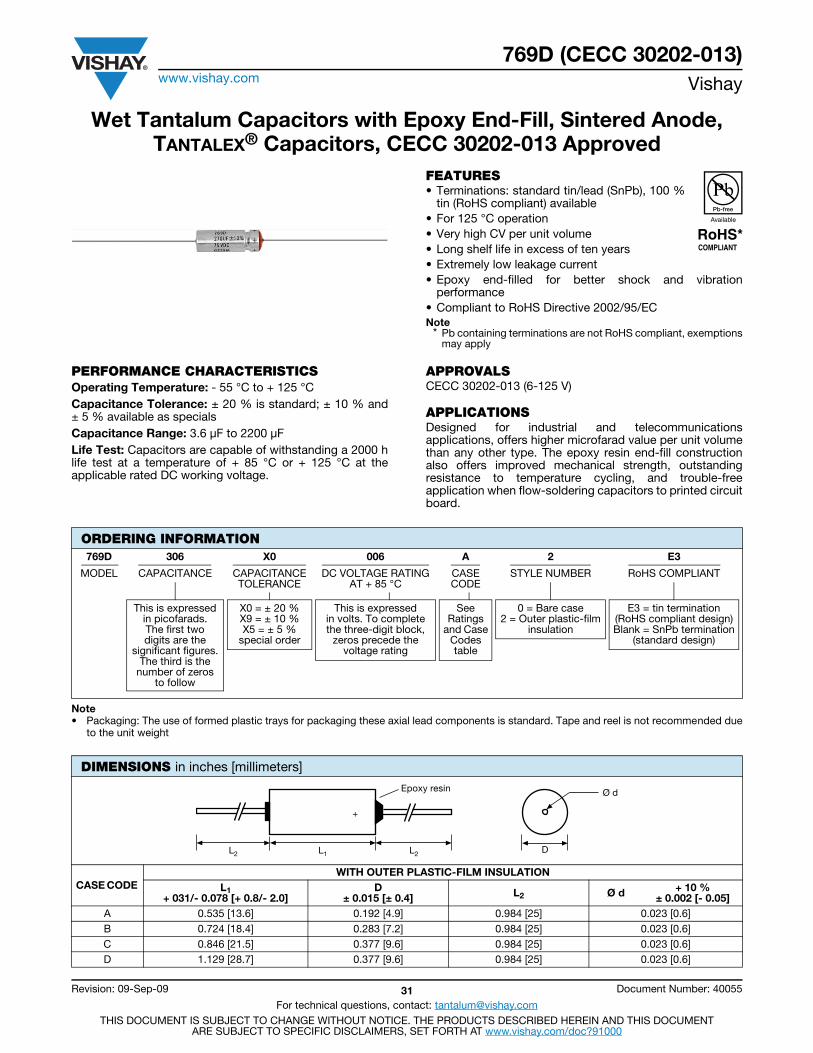
769D (CECC 30202-013)www.vishay.com Vishay
Revision: 09-Sep-09 31 Document Number: 40055
For technical questions, contact: [email protected] DOCUMENT IS SUBJECT TO CHANGE WITHOUT NOTICE. THE PRODUCTS DESCRIBED HEREIN AND THIS DOCUMENT
ARE SUBJECT TO SPECIFIC DISCLAIMERS, SET FORTH AT www.vishay.com/doc?91000
Wet Tantalum Capacitors with Epoxy End-Fill, Sintered Anode,TANTALEX® Capacitors, CECC 30202-013 Approved
FEATURES• Terminations: standard tin/lead (SnPb), 100 %
tin (RoHS compliant) available• For 125 °C operation• Very high CV per unit volume• Long shelf life in excess of ten years• Extremely low leakage current• Epoxy end-filled for better shock and vibration
performance• Compliant to RoHS Directive 2002/95/ECNote
* Pb containing terminations are not RoHS compliant, exemptionsmay apply
PERFORMANCE CHARACTERISTICSOperating Temperature: - 55 °C to + 125 °CCapacitance Tolerance: ± 20 % is standard; ± 10 % and± 5 % available as specialsCapacitance Range: 3.6 μF to 2200 μFLife Test: Capacitors are capable of withstanding a 2000 hlife test at a temperature of + 85 °C or + 125 °C at theapplicable rated DC working voltage.
APPROVALSCECC 30202-013 (6-125 V)
APPLICATIONSDesigned for industrial and telecommunicationsapplications, offers higher microfarad value per unit volumethan any other type. The epoxy resin end-fill constructionalso offers improved mechanical strength, outstandingresistance to temperature cycling, and trouble-freeapplication when flow-soldering capacitors to printed circuitboard.
Note• Packaging: The use of formed plastic trays for packaging these axial lead components is standard. Tape and reel is not recommended due
to the unit weight
ORDERING INFORMATION769D 306 X0 006 A 2 E3
MODEL CAPACITANCE CAPACITANCETOLERANCE
DC VOLTAGE RATINGAT + 85 °C
CASECODE
STYLE NUMBER RoHS COMPLIANT
This is expressedin picofarads.The first twodigits are the
significant figures.The third is the
number of zerosto follow
X0 = ± 20 % X9 = ± 10 %X5 = ± 5 %
special order
This is expressedin volts. To completethe three-digit block,
zeros precede thevoltage rating
SeeRatings
and CaseCodestable
0 = Bare case2 = Outer plastic-film
insulation
E3 = tin termination(RoHS compliant design)Blank = SnPb termination
(standard design)
DIMENSIONS in inches [millimeters]
CASE CODE WITH OUTER PLASTIC-FILM INSULATION
L1+ 031/- 0.078 [+ 0.8/- 2.0]
D± 0.015 [± 0.4] L2 Ø d + 10 %
± 0.002 [- 0.05] A 0.535 [13.6] 0.192 [4.9] 0.984 [25] 0.023 [0.6] B 0.724 [18.4] 0.283 [7.2] 0.984 [25] 0.023 [0.6] C 0.846 [21.5] 0.377 [9.6] 0.984 [25] 0.023 [0.6] D 1.129 [28.7] 0.377 [9.6] 0.984 [25] 0.023 [0.6]
+
Epoxy resin
DL2 L2L1
Ø d

769D (CECC 30202-013)www.vishay.com Vishay
Revision: 09-Sep-09 32 Document Number: 40055
For technical questions, contact: [email protected] DOCUMENT IS SUBJECT TO CHANGE WITHOUT NOTICE. THE PRODUCTS DESCRIBED HEREIN AND THIS DOCUMENT
ARE SUBJECT TO SPECIFIC DISCLAIMERS, SET FORTH AT www.vishay.com/doc?91000
STANDARD RATINGS
CAPACITANCE (μF)
CASE CODE PART NUMBER
MAX. DFAT + 25 °C
(%)
MAX. IMP.AT - 55 °C
()
MAX. DCL (μA) AT
MAX. CAPACITANCE CHANGE (%) AT
MAX. RMS
RIPPLE 120 Hz(mA)
+ 25 °C + 85 °C+ 125 °C - 55 °C + 85 °C + 125 °C
6 VDC AT + 85 °C; 4 VDC AT + 125 °C
30 A 769D306X0006A2 8 100 1 2 - 40 + 12 + 12 70
68 A 769D686X0006A2 18 59 1 2 - 40 + 16 + 16 80
140 B 769D147X0006B2 18 40 1 3 - 40 + 16 + 16 300
220 A 769D227X0006A2 40 22 2 9 - 65 + 16 + 16 90
270 B 769D277X0006B2 70 22 1 7 - 44 + 20 + 20 270
330 C 769D337X0006C2 43 25 2 8 - 44 + 16 + 16 500
560 C 769D567X0006C2 110 20 2 13 - 64 + 20 + 20 500
820 B 769D827X0006B2 68 20 3 14 - 80 + 20 + 20 280
1200 D 769D128X0006D2 60 20 3 12 - 80 + 25 + 25 800
1500 C 769D158X0006C2 82 10 5 20 - 85 + 25 + 25 540
2200 D 769D228X0006D2 80 15 9 30 - 80 + 25 + 25 800
8 VDC AT + 85 °C; 5 VDC AT + 125 °C
25 A 769D256X0008A2 7 100 1 2 - 40 + 12 + 12 70
56 A 769D566X0008A2 15 60 1 2 - 40 + 12 + 12 80
180 A 769D187X0008A2 36 28 2 9 - 60 + 16 + 16 90
220 B 769D227X0008B2 57 30 1 7 - 44 + 20 + 20 250
430 B 769D437X0008B2 42 25 3 14 - 80 + 20 + 20 270
430 C 769D437X0008C2 84 25 2 14 - 64 + 20 + 20 500
620 B 769D627X0008B2 53 20 3 14 - 80 + 20 + 20 280
680 B 769D687X0008B2 55 20 3 14 - 80 + 20 + 20 280
850 C 769D857X0008C2 65 20 4 16 - 80 + 25 + 25 500
850 D 769D857X0008D2 50 22 4 16 - 80 + 25 + 25 850
1200 C 769D128X0008C2 82 15 5 20 - 80 + 25 + 25 520
1600 D 769D168X0008D2 68 18 7 25 - 80 + 25 + 25 800
1800 D 769D188X0008D2 70 18 8 28 - 80 + 25 + 25 800
10 VDC AT + 85 °C; 7 VDC AT + 125 °C
20 A 769D206X0010A2 5 120 1 2 - 32 + 12 + 12 70
47 A 769D476X0010A2 15 90 1 2 - 36 + 16 + 16 80
100 A 769D107X0010A2 13 60 1 4 - 36 + 16 + 16 80
120 A 769D127X0010A2 32 50 2 9 - 50 + 16 + 16 80
140 A 769D147X0010A2 32 46 2 9 - 50 + 16 + 16 90
150 A 769D157X0010A2 32 40 2 9 - 50 + 16 + 16 90
180 B 769D187X0010B2 46 40 1 7 - 36 + 16 + 16 250
250 C 769D257X0010C2 32 35 2 10 - 40 + 16 + 16 500
390 C 769D397X0010C2 75 25 2 16 - 64 + 20 + 20 500
470 B 769D477X0010B2 35 21 3 16 - 70 + 20 + 20 280
510 B 769D517X0010B2 45 21 3 16 - 70 + 20 + 20 280
560 B 769D567X0010B2 50 21 3 16 - 70 + 20 + 20 280
750 D 769D757X0010D2 44 22 4 16 - 80 + 25 + 25 850
1000 C 769D108X0010C2 67 12 5 20 - 75 + 25 + 25 540
1300 D 769D138X0010D2 63 18 7 25 - 75 + 25 + 25 800
1500 D 769D158X0010D2 66 17 8 28 - 75 + 25 + 25 800
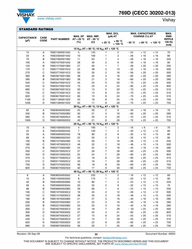
769D (CECC 30202-013)www.vishay.com Vishay
Revision: 09-Sep-09 33 Document Number: 40055
For technical questions, contact: [email protected] DOCUMENT IS SUBJECT TO CHANGE WITHOUT NOTICE. THE PRODUCTS DESCRIBED HEREIN AND THIS DOCUMENT
ARE SUBJECT TO SPECIFIC DISCLAIMERS, SET FORTH AT www.vishay.com/doc?91000
15 VDC AT + 85 °C; 10 VDC AT + 125 °C 15 A 769D156X0015A2 5 145 1 2 - 24 + 12 + 12 70 33 A 769D336X0015A2 10 100 1 2 - 28 + 16 + 16 80 70 B 769D706X0015B2 11 63 1 4 - 28 + 16 + 16 250 100 A 769D107X0015A2 28 40 2 9 - 40 + 16 + 16 80 120 B 769D127X0015B2 27 50 1 7 - 28 + 20 + 20 250 170 C 769D177X0015C2 22 38 2 10 - 32 + 16 + 16 500 270 C 769D277X0015C2 50 30 2 16 - 56 + 20 + 20 500 360 B 769D367X0015B2 38 22 3 16 - 60 + 20 + 20 280 390 B 769D397X0015B2 38 21 3 16 - 60 + 20 + 20 280 540 C 769D547X0015C2 45 25 5 20 - 70 + 25 + 25 500 540 D 769D547X0015D2 15 23 3 24 - 80 + 25 + 25 850 680 C 769D687X0015C2 50 13 5 20 - 70 + 25 + 25 510 750 C 769D757X0015C2 52 13 6 24 - 70 + 25 + 25 510 820 C 769D827X0015C2 60 13 6 24 - 70 + 25 + 25 510 1100 D 769D118X0015D2 53 18 8 25 - 70 + 25 + 25 750 1200 D 769D128X0015D2 55 17 8 28 - 70 + 25 + 25 750
20 VDC AT + 85 °C; 13 VDC AT + 125 °C 82 A 769D826X0020A2 25 50 2 9 - 40 + 16 + 16 70
330 B 769D337X0020B2 30 21 3 16 - 60 + 20 + 20 280 560 C 769D567X0020C2 40 20 5 20 - 70 + 25 + 25 510 1000 D 769D108X0020D2 40 21 8 28 - 70 + 25 + 25 750
25 VDC AT + 85 °C; 15 VDC AT + 125 °C 10 A 769D106X0025A2 4 190 1 2 - 16 + 9 + 9 70 22 A 769D226X0025A2 7 140 1 2 - 20 + 12 + 12 80 50 A 769D506X0025A2 18 80 2 9 - 35 + 15 + 15 80 68 A 769D686X0025A2 22 50 2 9 - 35 + 15 + 15 80
100 B 769D107X0025B2 15 50 1 10 - 28 + 15 + 15 250 180 C 769D187X0025C2 46 32 2 18 - 48 + 15 + 15 500 270 B 769D277X0025B2 24 22 3 16 - 45 + 16 + 16 280 350 C 769D357X0025C2 27 26 7 28 - 60 + 25 + 25 500 350 D 769D357X0025D2 25 24 7 28 - 80 + 25 + 25 850 470 C 769D477X0025C2 33 18 6 24 - 60 + 25 + 25 510 510 C 769D517X0025C2 33 16 7 28 - 60 + 25 + 25 510 750 D 769D757X0025D2 36 18 8 29 - 60 + 25 + 25 750 820 D 769D827X0025D2 40 17 9 30 - 60 + 25 + 25 750
30 VDC AT + 85 °C; 20 VDC AT + 125 °C 8 A 769D805X0030A2 4 235 1 2 - 16 + 12 + 12 60 15 A 769D156X0030A2 8 175 1 2 - 20 + 12 + 12 80 40 B 769D406X0030B2 10 80 1 5 - 24 + 12 + 12 250 56 A 769D566X0030A2 20 55 2 9 - 32 + 15 + 15 70 68 B 769D686X0030B2 26 60 1 8 - 24 + 15 + 15 250 100 C 769D107X0030C2 16 45 2 12 - 28 + 12 + 12 500 150 C 769D157X0030C2 38 35 2 18 - 48 + 15 + 15 500 180 B 769D187X0030B2 21 27 3 16 - 40 + 16 + 16 280 200 B 769D207X0030B2 21 25 3 16 - 40 + 16 + 16 280 220 B 769D227X0030B2 23 25 3 16 - 40 + 16 + 16 280 300 C 769D307X0030C2 25 18 7 28 - 55 + 25 + 25 500 300 D 769D307X0030D2 27 25 4 31 - 60 + 25 + 25 820 390 C 769D397X0030C2 27 15 6 24 - 55 + 20 + 25 510 430 C 769D437X0030C2 27 15 7 28 - 55 + 25 + 25 510 620 D 769D627X0030D2 32 22 8 29 - 60 + 20 + 25 750 680 D 769D687X0030D2 36 20 7 25 - 60 + 25 + 25 750
STANDARD RATINGS
CAPACITANCE (μF)
CASE CODE PART NUMBER
MAX. DFAT + 25 °C
(%)
MAX. IMP.AT - 55 °C
()
MAX. DCL (μA) AT
MAX. CAPACITANCE CHANGE (%) AT
MAX. RMS
RIPPLE 120 Hz(mA)
+ 25 °C + 85 °C+ 125 °C - 55 °C + 85 °C + 125 °C
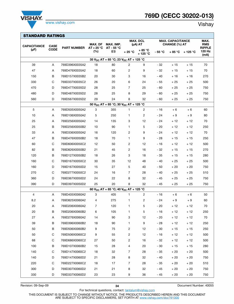
769D (CECC 30202-013)www.vishay.com Vishay
Revision: 09-Sep-09 34 Document Number: 40055
For technical questions, contact: [email protected] DOCUMENT IS SUBJECT TO CHANGE WITHOUT NOTICE. THE PRODUCTS DESCRIBED HEREIN AND THIS DOCUMENT
ARE SUBJECT TO SPECIFIC DISCLAIMERS, SET FORTH AT www.vishay.com/doc?91000
35 VDC AT + 85 °C; 23 VDC AT + 125 °C
39 A 769D396X0035A2 18 80 2 9 - 32 + 15 + 15 70
47 A 769D476X0035A2 18 60 2 9 - 32 + 15 + 15 70
150 B 769D157X0035B2 20 30 3 16 - 40 + 16 + 16 270
330 C 769D337X0035C2 26 20 6 24 - 55 + 25 + 25 500
470 D 769D477X0035D2 28 25 7 25 - 60 + 25 + 25 750
480 D 769D487X0035D2 28 25 8 29 - 60 + 25 + 25 750
560 D 769D567X0035D2 29 24 8 32 - 60 + 25 + 25 750
50 VDC AT + 85 °C; 30 VDC AT + 125 °C
5 A 769D505X0050A2 3 355 1 2 - 16 + 6 + 6 60
10 A 769D106X0050A2 5 250 1 2 - 24 + 9 + 9 80
25 A 769D256X0050A2 14 135 3 12 - 24 + 12 + 12 70
25 B 769D256X0050B2 10 90 1 5 - 20 + 12 + 12 250
33 A 769D336X0050A2 16 120 2 9 - 24 + 12 + 12 70
47 B 769D476X0050B2 18 70 1 9 - 28 + 15 + 15 250
60 C 769D606X0050C2 12 50 2 12 - 16 + 12 + 12 500
82 B 769D826X0050B2 21 45 2 16 - 32 + 15 + 15 270
120 B 769D127X0050B2 18 26 3 18 - 35 + 15 + 15 280
160 C 769D167X0050C2 30 35 12 48 - 40 + 25 + 25 500
160 D 769D167X0050D2 15 27 5 40 - 50 + 20 + 20 750
270 C 769D277X0050C2 24 16 7 28 - 40 + 25 + 25 510
360 D 769D367X0050D2 24 22 8 32 - 45 + 25 + 25 750
390 D 769D397X0050D2 25 20 8 32 - 45 + 25 + 25 750
60 VDC AT + 85 °C; 40 VDC AT + 125 °C
4 A 769D405X0060A2 3 405 1 2 - 16 + 6 + 6 50
8.2 A 769D825X0060A2 4 275 1 2 - 24 + 9 + 9 60
20 A 769D206X0060A2 7 120 1 5 - 20 + 12 + 12 70
20 B 769D206X0060B2 6 105 1 5 - 16 + 12 + 12 250
27 A 769D276X0060A2 14 90 3 12 - 20 + 12 + 12 70
39 B 769D396X0060B2 18 90 1 9 - 28 + 12 + 12 250
50 B 769D506X0060B2 9 75 2 12 - 30 + 15 + 15 250
50 C 769D506X0060C2 9 55 2 12 - 16 + 12 + 12 500
68 C 769D686X0060C2 27 50 2 16 - 32 + 12 + 12 500
100 B 769D107X0060B2 15 28 4 20 - 30 + 15 + 15 280
140 C 769D147X0060C2 18 32 7 28 - 35 + 20 + 20 500
140 D 769D147X0060D2 21 28 8 32 - 40 + 20 + 20 750
220 C 769D227X0060C2 18 17 7 28 - 35 + 20 + 20 510
300 D 769D307X0060D2 21 21 8 32 - 45 + 20 + 20 750
330 D 769D337X0060D2 23 23 9 36 - 45 + 20 + 20 750
STANDARD RATINGS
CAPACITANCE (μF)
CASE CODE PART NUMBER
MAX. DFAT + 25 °C
(%)
MAX. IMP.AT - 55 °C
()
MAX. DCL (μA) AT
MAX. CAPACITANCE CHANGE (%) AT
MAX. RMS
RIPPLE 120 Hz(mA)
+ 25 °C + 85 °C+ 125 °C - 55 °C + 85 °C + 125 °C

769D (CECC 30202-013)www.vishay.com Vishay
Revision: 09-Sep-09 35 Document Number: 40055
For technical questions, contact: [email protected] DOCUMENT IS SUBJECT TO CHANGE WITHOUT NOTICE. THE PRODUCTS DESCRIBED HEREIN AND THIS DOCUMENT
ARE SUBJECT TO SPECIFIC DISCLAIMERS, SET FORTH AT www.vishay.com/doc?91000
75 VDC AT + 85 °C; 50 VDC AT + 125 °C
6.8 A 769D685X0075A2 4 300 1 2 - 20 + 9 + 9 60
8.2 A 769D825X0075A2 12 200 1.5 7 - 16 + 12 + 12 60
12 A 769D126X0075A2 12 155 2 9 - 16 + 12 + 12 70
15 A 769D156X0075A2 12 130 3 12 - 16 + 12 + 12 70
15 B 769D156X0075B2 6 135 1 5 - 16 + 9 + 9 250
18 A 769D186X0075A2 12 100 3 12 - 16 + 12 + 12 70
22 A 769D226X0075A2 12 80 3 12 - 16 + 12 + 12 70
33 B 769D336X0075B2 15 90 1 10 - 24 + 15 + 15 250
40 C 769D406X0075C2 13 60 2 12 - 16 + 12 + 12 500
47 B 769D476X0075B2 20 75 3.5 20 - 25 + 15 + 15 260
56 B 769D566X0075B2 20 70 2 16 - 25 + 15 + 15 260
56 C 769D566X0075C2 22 60 2 17 - 28 + 15 + 15 500
68 B 769D686X0075B2 12 42 4 24 - 25 + 15 + 15 280
82 B 769D826X0075B2 12 30 4 24 - 25 + 15 + 15 280
100 C 769D107X0075C2 18 33 8 32 - 30 + 20 + 20 500
110 C 769D117X0075C2 18 33 8 32 - 30 + 20 + 20 500
110 D 769D117X0075D2 15 29 5 36 - 35 + 20 + 20 750
120 C 769D127X0075C2 18 28 6 26 - 30 + 20 + 20 500
150 C 769D157X0075C2 18 24 7 28 - 30 + 20 + 20 500
180 C 769D187X0075C2 18 17 8 32 - 30 + 20 + 20 510
220 D 769D227X0075D2 16 24 9 36 - 40 + 20 + 20 750
240 D 769D247X0075D2 17 24 9 36 - 40 + 20 + 20 750
270 D 769D277X0075D2 18 22 10 40 - 30 + 20 + 20 750
100 VDC AT + 85 °C; 70 VDC AT + 125 °C
4.7 A 769D475X0100A2 3 500 1 2 - 16 + 6 + 6 60
10 A 769D106X0100A2 12 200 3 12 - 16 + 12 + 12 60
11 B 769D116X0100B2 4 200 1 4 - 16 + 6 + 6 250
22 B 769D226X0100B2 10 100 1 9 - 16 + 6 + 6 250
30 C 769D306X0100C2 8 85 2 12 - 16 + 8 + 8 500
39 B 769D396X0100B2 20 80 5 24 - 25 + 15 + 15 250
43 C 769D436X0100C2 16 70 2 17 - 20 + 8 + 8 500
68 C 769D686X0100C2 18 40 10 40 - 30 + 20 + 20 500
86 D 769D866X0100D2 15 30 5 35 - 25 + 20 + 20 750
120 D 769D127X0100D2 25 36 12 48 - 40 + 20 + 20 750
125 VDC AT + 85 °C; 85 VDC AT + 125 °C
3.6 A 769D365X0125A2 4 615 1 2 - 16 + 8 + 8 50
6.8 A 769D685X0125A2 12 300 3 12 - 16 + 12 + 12 50
9 A 769D905X0125A2 12 240 4 15 - 16 + 12 + 12 50
9 B 769D905X0125B2 9 220 1 5 - 16 + 6 + 6 250
14 B 769D146X0125B2 10 160 1 7 - 16 + 7 + 7 250
25 C 769D256X0125C2 16 120 2 13 - 16 + 10 + 10 500
27 B 769D276X0125B2 20 90 5 24 - 25 + 15 + 15 250
47 C 769D476X0125C2 18 50 10 40 - 30 + 20 + 20 500
80 D 769D806X0125D2 20 34 9 50 - 20 + 20 + 20 750
82 D 769D826X0125D2 25 40 12 48 - 40 + 20 + 20 750
STANDARD RATINGS
CAPACITANCE (μF)
CASE CODE PART NUMBER
MAX. DFAT + 25 °C
(%)
MAX. IMP.AT - 55 °C
()
MAX. DCL (μA) AT
MAX. CAPACITANCE CHANGE (%) AT
MAX. RMS
RIPPLE 120 Hz(mA)
+ 25 °C + 85 °C+ 125 °C - 55 °C + 85 °C + 125 °C
Contents
M39006/22/25 ................. 60
135D ............................... 37
735D/DE, CT79.............. 50
Tantalum Case
Standard
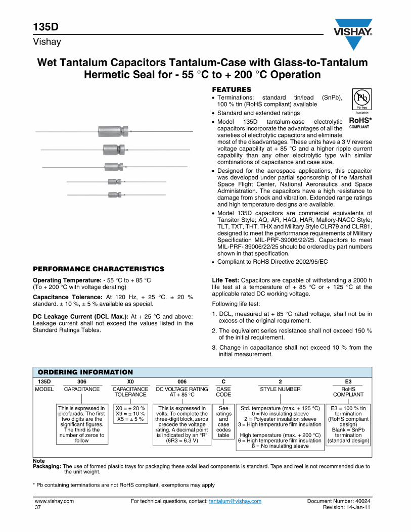
135DVishay
Wet Tantalum Capacitors Tantalum-Case with Glass-to-Tantalum Hermetic Seal for - 55 °C to + 200 °C Operation
www.vishay.com For technical questions, contact: [email protected] Document Number: 4002437 Revision: 14-Jan-11
FEATURES Terminations: standard tin/lead (SnPb),
100 % tin (RoHS compliant) available Standard and extended ratings
Model 135D tantalum-case electrolyticcapacitors incorporate the advantages of all thevarieties of electrolytic capacitors and eliminatemost of the disadvantages. These units have a 3 V reversevoltage capability at + 85 °C and a higher ripple currentcapability than any other electrolytic type with similarcombinations of capacitance and case size.
Designed for the aerospace applications, this capacitorwas developed under partial sponsorship of the MarshallSpace Flight Center, National Aeronautics and SpaceAdministration. The capacitors have a high resistance todamage from shock and vibration. Extended range ratingsand high temperature designs are available.
Model 135D capacitors are commercial equivalents ofTansitor Style; AQ, AR, HAQ, HAR, Mallory-NACC Style;TLT, TXT, THT, THX and Military Style CLR79 and CLR81,designed to meet the performance requirements of MilitarySpecification MIL-PRF-39006/22/25. Capacitors to meetMIL-PRF- 39006/22/25 should be ordered by part numbersshown in that specification.
Compliant to RoHS Directive 2002/95/ECPERFORMANCE CHARACTERISTICS
Operating Temperature: - 55 °C to + 85 °C (To + 200 °C with voltage derating)
Capacitance Tolerance: At 120 Hz, + 25 °C. ± 20 %standard. ± 10 %, ± 5 % available as special.
DC Leakage Current (DCL Max.): At + 25 °C and above:Leakage current shall not exceed the values listed in theStandard Ratings Tables.
Life Test: Capacitors are capable of withstanding a 2000 hlife test at a temperature of + 85 °C or + 125 °C at theapplicable rated DC working voltage.
Following life test:
1. DCL, measured at + 85 °C rated voltage, shall not be inexcess of the original requirement.
2. The equivalent series resistance shall not exceed 150 %of the initial requirement.
3. Change in capacitance shall not exceed 10 % from theinitial measurement.
* Pb containing terminations are not RoHS compliant, exemptions may apply
ORDERING INFORMATION135D 306 X0 006 C 2 E3
MODEL CAPACITANCE CAPACITANCE TOLERANCE
DC VOLTAGE RATING AT + 85 C
CASE CODE
STYLE NUMBER RoHS COMPLIANT
This is expressed in picofarads. The first
two digits are the significant figures.
The third is the number of zeros to
follow
X0 = ± 20 % X9 = ±10 %X5 = ±5 %
This is expressed in volts. To complete the three-digit block, zeros
precede the voltage rating. A decimal point is indicated by an “R”
(6R3 = 6.3 V)
See ratings
and case
codestable
Std. temperature (max. + 125 °C) 0 = No insulating sleeve
2 = Polyester insulation sleeve3 = High temperature film insulation
High temperature (max. + 200 °C)6 = High temperature film insulation
8 = No insulating sleeve
E3 = 100 % tin termination
(RoHS compliant design)
Blank = SnPb termination
(standard design)
NotePackaging: The use of formed plastic trays for packaging these axial lead components is standard. Tape and reel is not recommended due to
the unit weight.

Document Number: 40024 For technical questions, contact: [email protected] www.vishay.comRevision: 14-Jan-11 38
135DWet Tantalum Capacitors Tantalum-Case with Glass-to-Tantalum
Hermetic Seal for - 55 °C to + 200 °C OperationVishay
DIMENSIONS in inches [millimeters]
CASE CODE D L1 L2
(Max.) E WEIGHT
(g) (Max.)
TYPE 135D
DCLR 79/81 EQUIV.
C T1 0.188 ± 0.016 [4.78 ± 0.41]
0.453 + 0.031 - 0.016 [11.51 + 0.79 - 0.41]
0.734 [18.64]
1.500 ± 0.250 [38.10 ± 6.35] 2.6
F T2 0.281 ± 0.016 [7.14 ± 0.41]
0.641 + 0.031 - 0.016 [16.28 + 0.79 - 0.41]
0.922 [23.42]
2.250 ± 0.250 [57.15 ± 6.35] 6.2
T T3 0.375 ± 0.016 [9.53 ± 0.41]
0.766 + 0.031 - 0.016 [19.46 + 0.79 - 0.41]
1.047 [26.59]
2.250 ± 0.250[57.15 ± 6.35] 11.6
K T4 0.375 ± 0.016 [9.53 ± 0.41]
1.062 + 0.031 - 0.016 [26.97 + 0.79 - 0.41]
1.343 [34.11]
2.250 ± 0.250[57.15 ± 6.35] 17.7
Note• For insulated parts, add 0.015" [0.38] to the diameter. The insulation shall lap over the ends of the capacitor body.
D
0.0253 ± 0.002 [0.64 ± 0.05] Dia.(No. 22 AWG) Tinned Nickel Leads
Solderable and Weldable
E E
L2
L1
Tantalum
Weld
STANDARD RATINGS
CAPACITANCE (µF)
CASE CODE PART NUMBER (1)
MAX. ESRat
+ 25 °C 120 Hz
()
MAX. IMP.at
- 55 °C120 Hz
()
MAX. DCL (µA)at
MAX. CAPACITANCE CHANGE (%) at
MAX. RIPPLE 40 kHz
IRMS (mA)
+ 25 °C + 85 °C+ 125 °C - 55 °C + 85 °C + 125 °C
6 WVDC at + 85 °C . . . 4 WVDC at + 125 °C. . . 3.6 WVDC at + 200 °C 30 C 135D306X0006C2 4.0 100 1.0 2.0 - 40 + 10.5 + 12 820 68 C 135D686X0006C2 3.2 60 1.0 2.0 - 40 + 14 + 16 960 140 F 135D147X0006F2 2.0 40 1.0 3.0 - 40 + 14 + 16 1200 270 F 135D277X0006F2 2.2 25 1.0 6.5 - 44 + 17.5 + 20 1375 330 T 135D337X0006T2 1.4 20 2.0 7.9 - 44 + 14 + 16 1800 560 T 135D567X0006T2 1.3 25 2.0 13.0 - 64 + 17.5 + 20 1900 1200 K 135D128X0006K2 1.0 20 3.0 14.0 - 80 + 25 + 25 2265
8 WVDC at + 85 °C . . . 5 WVDC at + 125 °C . . . 4.8 WVDC at + 200 °C 25 C 135D256X0008C2 4.0 100 1.0 2.0 - 40 + 10.5 + 12 820 56 C 135D566X0008C2 3.3 59 1.0 2.0 - 40 + 14 + 16 900 120 F 135D127X0008F2 2.6 50 1.0 2.0 - 44 + 17.5 + 20 1230 220 F 135D227X0008F2 2.4 30 1.0 7.0 - 44 + 17.5 + 20 1370 290 T 135D297X0008T2 1.8 25 2.0 6.0 - 64 + 17.5 + 20 1770 430 T 135D437X0008T2 1.4 25 2.0 14.0 - 64 + 17.5 + 20 1825 850 K 135D857X0008K2 1.0 22 4.0 16.0 - 80 + 25 + 25 2330
10 WVDC at + 85 °C . . . 7 WVDC at + 125 °C . . . 6 WVDC at + 200 °C 20 C 135D206X0010C2 4.0 120 1.0 2.0 - 32 + 10.5 + 12 820 47 C 135D476X0010C2 3.7 90 1.0 2.0 - 36 + 14 + 16 855 100 F 135D107X0010F2 2.4 60 1.0 4.0 - 36 + 14 + 16 1200 180 F 135D187X0010F2 2.2 40 1.0 7.0 - 36 + 14 + 16 1365 250 T 135D257X0010T2 1.8 30 2.0 10.0 - 40 + 14 + 16 1720 390 T 135D397X0010T2 1.5 25 2.0 16.0 - 64 + 17.5 + 20 1800 750 K 135D757X0010K2 1.0 23 4.0 16.0 - 80 + 25 + 25 2360
15 WVDC at + 85 °C . . . 10 WVDC at + 125 °C . . . 9 WVDC at + 200 °C 15 C 135D156X0015C2 4.4 155 1.0 2.0 - 24 + 10.5 + 12 780 33 C 135D336X0015C2 4.0 90 1.0 2.0 - 28 + 14 + 16 820 70 F 135D706X0015F2 2.8 75 1.0 4.0 - 28 + 14 + 16 1150 120 F 135D127X0015F2 2.6 50 1.0 7.0 - 28 + 17.5 + 20 1450 170 T 135D177X0015T2 2.4 35 2.0 10.0 - 32 + 14 + 16 1480 270 T 135D277X0015T2 2.2 30 2.0 16.0 - 56 + 17.5 + 20 1740 540 K 135D547X0015K2 1.0 23 6.0 24.0 - 80 + 25 + 25 2330
Note(1) Part Numbers are for units with ± 20 % capacitance tolerance, standard + 125 °C maximum temperature, standard polyesterfilm insulation,
and tin-lead terminations. For other capacitance tolerances, other maximum temperatures, insulation and termination options, please consultORDERING INFORMATION on page 1 for proper part number.
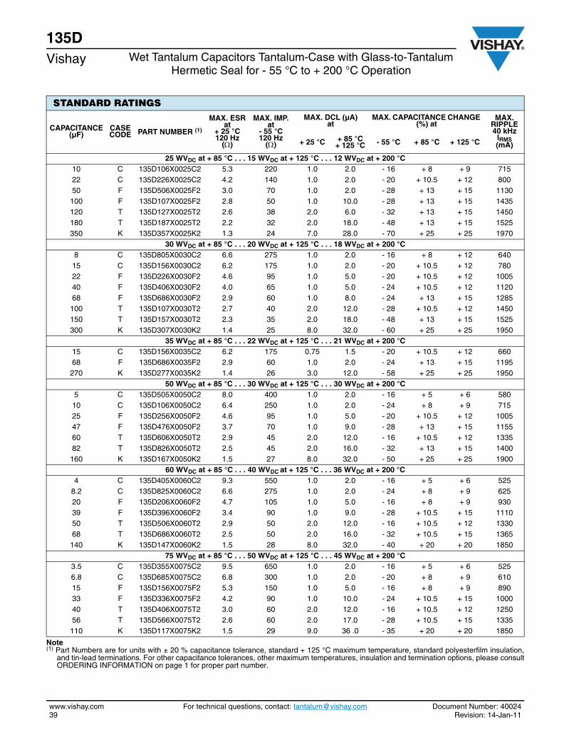
135DVishay Wet Tantalum Capacitors Tantalum-Case with Glass-to-Tantalum
Hermetic Seal for - 55 °C to + 200 °C Operation
www.vishay.com For technical questions, contact: [email protected] Document Number: 4002439 Revision: 14-Jan-11
STANDARD RATINGS
CAPACITANCE (µF)
CASE CODE PART NUMBER (1)
MAX. ESRat
+ 25 °C 120 Hz
()
MAX. IMP.at
- 55 °C120 Hz
()
MAX. DCL (µA)at
MAX. CAPACITANCE CHANGE (%) at
MAX. RIPPLE 40 kHz
IRMS (mA)+ 25 °C + 85 °C
+ 125 °C - 55 °C + 85 °C + 125 °C
25 WVDC at + 85 °C . . . 15 WVDC at + 125 °C . . . 12 WVDC at + 200 °C 10 C 135D106X0025C2 5.3 220 1.0 2.0 - 16 + 8 + 9 715 22 C 135D226X0025C2 4.2 140 1.0 2.0 - 20 + 10.5 + 12 800 50 F 135D506X0025F2 3.0 70 1.0 2.0 - 28 + 13 + 15 1130 100 F 135D107X0025F2 2.8 50 1.0 10.0 - 28 + 13 + 15 1435 120 T 135D127X0025T2 2.6 38 2.0 6.0 - 32 + 13 + 15 1450 180 T 135D187X0025T2 2.2 32 2.0 18.0 - 48 + 13 + 15 1525 350 K 135D357X0025K2 1.3 24 7.0 28.0 - 70 + 25 + 25 1970
30 WVDC at + 85 °C . . . 20 WVDC at + 125 °C . . . 18 WVDC at + 200 °C 8 C 135D805X0030C2 6.6 275 1.0 2.0 - 16 + 8 + 12 640 15 C 135D156X0030C2 6.2 175 1.0 2.0 - 20 + 10.5 + 12 780 22 F 135D226X0030F2 4.6 95 1.0 5.0 - 20 + 10.5 + 12 100540 F 135D406X0030F2 4.0 65 1.0 5.0 - 24 + 10.5 + 12 1120 68 F 135D686X0030F2 2.9 60 1.0 8.0 - 24 + 13 + 15 1285 100 T 135D107X0030T2 2.7 40 2.0 12.0 - 28 + 10.5 + 12 1450 150 T 135D157X0030T2 2.3 35 2.0 18.0 - 48 + 13 + 15 1525 300 K 135D307X0030K2 1.4 25 8.0 32.0 - 60 + 25 + 25 1950
35 WVDC at + 85 °C . . . 22 WVDC at + 125 °C . . . 21 WVDC at + 200 °C 15 C 135D156X0035C2 6.2 175 0.75 1.5 - 20 + 10.5 + 12 660 68 F 135D686X0035F2 2.9 60 1.0 2.0 - 24 + 13 + 15 1195 270 K 135D277X0035K2 1.4 26 3.0 12.0 - 58 + 25 + 25 1950
50 WVDC at + 85 °C . . . 30 WVDC at + 125 °C . . . 30 WVDC at + 200 °C 5 C 135D505X0050C2 8.0 400 1.0 2.0 - 16 + 5 + 6 580 10 C 135D106X0050C2 6.4 250 1.0 2.0 - 24 + 8 + 9 715 25 F 135D256X0050F2 4.6 95 1.0 5.0 - 20 + 10.5 + 12 1005 47 F 135D476X0050F2 3.7 70 1.0 9.0 - 28 + 13 + 15 1155 60 T 135D606X0050T2 2.9 45 2.0 12.0 - 16 + 10.5 + 12 1335 82 T 135D826X0050T2 2.5 45 2.0 16.0 - 32 + 13 + 15 1400 160 K 135D167X0050K2 1.5 27 8.0 32.0 - 50 + 25 + 25 1900
60 WVDC at + 85 °C . . . 40 WVDC at + 125 °C . . . 36 WVDC at + 200 °C 4 C 135D405X0060C2 9.3 550 1.0 2.0 - 16 + 5 + 6 525
8.2 C 135D825X0060C2 6.6 275 1.0 2.0 - 24 + 8 + 9 625 20 F 135D206X0060F2 4.7 105 1.0 5.0 - 16 + 8 + 9 930 39 F 135D396X0060F2 3.4 90 1.0 9.0 - 28 + 10.5 + 15 1110 50 T 135D506X0060T2 2.9 50 2.0 12.0 - 16 + 10.5 + 12 1330 68 T 135D686X0060T2 2.5 50 2.0 16.0 - 32 + 10.5 + 15 1365 140 K 135D147X0060K2 1.5 28 8.0 32.0 - 40 + 20 + 20 1850
75 WVDC at + 85 °C . . . 50 WVDC at + 125 °C . . . 45 WVDC at + 200 °C 3.5 C 135D355X0075C2 9.5 650 1.0 2.0 - 16 + 5 + 6 525 6.8 C 135D685X0075C2 6.8 300 1.0 2.0 - 20 + 8 + 9 610 15 F 135D156X0075F2 5.3 150 1.0 5.0 - 16 + 8 + 9 890 33 F 135D336X0075F2 4.2 90 1.0 10.0 - 24 + 10.5 + 15 1000 40 T 135D406X0075T2 3.0 60 2.0 12.0 - 16 + 10.5 + 12 1250 56 T 135D566X0075T2 2.6 60 2.0 17.0 - 28 + 10.5 + 15 1335 110 K 135D117X0075K2 1.5 29 9.0 36 .0 - 35 + 20 + 20 1850
Note(1) Part Numbers are for units with ± 20 % capacitance tolerance, standard + 125 °C maximum temperature, standard polyesterfilm insulation,
and tin-lead terminations. For other capacitance tolerances, other maximum temperatures, insulation and termination options, please consultORDERING INFORMATION on page 1 for proper part number.
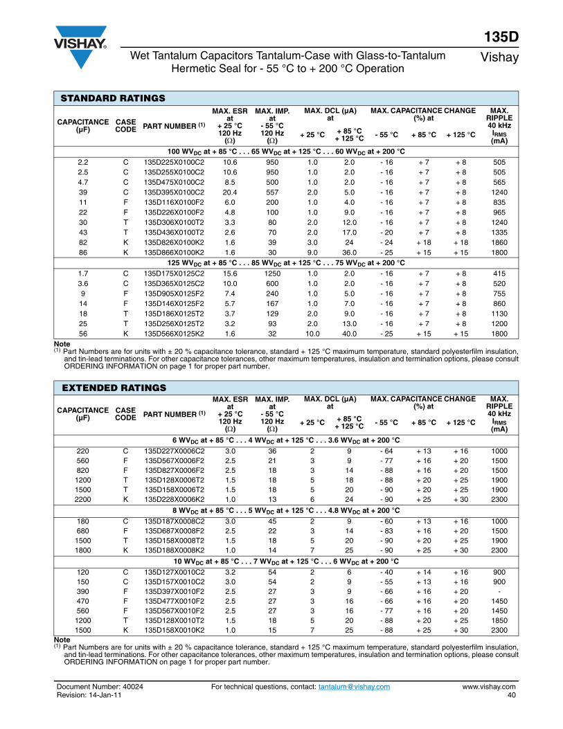
Document Number: 40024 For technical questions, contact: [email protected] www.vishay.comRevision: 14-Jan-11 40
135DWet Tantalum Capacitors Tantalum-Case with Glass-to-Tantalum
Hermetic Seal for - 55 °C to + 200 °C OperationVishay
CAPACITANCE (µF)
CASE CODE PART NUMBER (1)
MAX. ESRat
+ 25 °C 120 Hz
()
MAX. IMP.at
- 55 °C120 Hz
()
MAX. DCL (µA)at
MAX. CAPACITANCE CHANGE (%) at
MAX. RIPPLE 40 kHz
IRMS (mA)
+ 25 °C + 85 °C+ 125 °C - 55 °C + 85 °C + 125 °C
100 WVDC at + 85 °C . . . 65 WVDC at + 125 °C . . . 60 WVDC at + 200 °C 2.2 C 135D225X0100C2 10.6 950 1.0 2.0 - 16 + 7 + 8 505 2.5 C 135D255X0100C2 10.6 950 1.0 2.0 - 16 + 7 + 8 505 4.7 C 135D475X0100C2 8.5 500 1.0 2.0 - 16 + 7 + 8 565 39 C 135D395X0100C2 20.4 557 2.0 5.0 - 16 + 7 + 8 124011 F 135D116X0100F2 6.0 200 1.0 4.0 - 16 + 7 + 8 835 22 F 135D226X0100F2 4.8 100 1.0 9.0 - 16 + 7 + 8 965 30 T 135D306X0100T2 3.3 80 2.0 12.0 - 16 + 7 + 8 1240 43 T 135D436X0100T2 2.6 70 2.0 17.0 - 20 + 7 + 8 1335 82 K 135D826X0100K2 1.6 39 3.0 24 - 24 + 18 + 18 186086 K 135D866X0100K2 1.6 30 9.0 36.0 - 25 + 15 + 15 1800
125 WVDC at + 85 °C . . . 85 WVDC at + 125 °C . . . 75 WVDC at + 200 °C 1.7 C 135D175X0125C2 15.6 1250 1.0 2.0 - 16 + 7 + 8 415 3.6 C 135D365X0125C2 10.0 600 1.0 2.0 - 16 + 7 + 8 520 9 F 135D905X0125F2 7.4 240 1.0 5.0 - 16 + 7 + 8 755 14 F 135D146X0125F2 5.7 167 1.0 7.0 - 16 + 7 + 8 860 18 T 135D186X0125T2 3.7 129 2.0 9.0 - 16 + 7 + 8 1130 25 T 135D256X0125T2 3.2 93 2.0 13.0 - 16 + 7 + 8 120056 K 135D566X0125K2 1.6 32 10.0 40.0 - 25 + 15 + 15 1800
Note(1) Part Numbers are for units with ± 20 % capacitance tolerance, standard + 125 °C maximum temperature, standard polyesterfilm insulation,
and tin-lead terminations. For other capacitance tolerances, other maximum temperatures, insulation and termination options, please consultORDERING INFORMATION on page 1 for proper part number.
STANDARD RATINGS
EXTENDED RATINGS
CAPACITANCE (µF)
CASE CODE PART NUMBER (1)
MAX. ESRat
+ 25 °C 120 Hz
()
MAX. IMP.at
- 55 °C120 Hz
()
MAX. DCL (µA)at
MAX. CAPACITANCE CHANGE (%) at
MAX. RIPPLE 40 kHz
IRMS (mA)
+ 25 °C + 85 °C+ 125 °C - 55 °C + 85 °C + 125 °C
6 WVDC at + 85 °C . . . 4 WVDC at + 125 °C . . . 3.6 WVDC at + 200 °C 220 C 135D227X0006C2 3.0 36 2 9 - 64 + 13 + 16 1000 560 F 135D567X0006F2 2.5 21 3 9 - 77 + 16 + 20 1500 820 F 135D827X0006F2 2.5 18 3 14 - 88 + 16 + 20 1500 1200 T 135D128X0006T2 1.5 18 5 18 - 88 + 20 + 25 1900 1500 T 135D158X0006T2 1.5 18 5 20 - 90 + 20 + 25 1900 2200 K 135D228X0006K2 1.0 13 6 24 - 90 + 25 + 30 2300
8 WVDC at + 85 °C . . . 5 WVDC at + 125 °C . . . 4.8 WVDC at + 200 °C 180 C 135D187X0008C2 3.0 45 2 9 - 60 + 13 + 16 1000 680 F 135D687X0008F2 2.5 22 3 14 - 83 + 16 + 20 1500 1500 T 135D158X0008T2 1.5 18 5 20 - 90 + 20 + 25 1900 1800 K 135D188X0008K2 1.0 14 7 25 - 90 + 25 + 30 2300
10 WVDC at + 85 °C . . . 7 WVDC at + 125 °C . . . 6 WVDC at + 200 °C 120 C 135D127X0010C2 3.2 54 2 6 - 40 + 14 + 16 900 150 C 135D157X0010C2 3.0 54 2 9 - 55 + 13 + 16 900 390 F 135D397X0010F2 2.5 27 3 9 - 66 + 16 + 20 -470 F 135D477X0010F2 2.5 27 3 16 - 66 + 16 + 20 1450 560 F 135D567X0010F2 2.5 27 3 16 - 77 + 16 + 20 1450 1200 T 135D128X0010T2 1.5 18 5 20 - 88 + 20 + 25 1850 1500 K 135D158X0010K2 1.0 15 7 25 - 88 + 25 + 30 2300
Note(1) Part Numbers are for units with ± 20 % capacitance tolerance, standard + 125 °C maximum temperature, standard polyesterfilm insulation,
and tin-lead terminations. For other capacitance tolerances, other maximum temperatures, insulation and termination options, please consultORDERING INFORMATION on page 1 for proper part number.
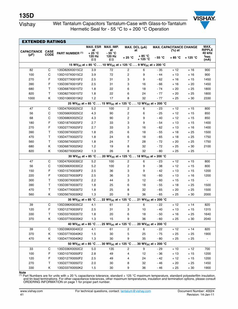
135DVishay Wet Tantalum Capacitors Tantalum-Case with Glass-to-Tantalum
Hermetic Seal for - 55 °C to + 200 °C Operation
www.vishay.com For technical questions, contact: [email protected] Document Number: 4002441 Revision: 14-Jan-11
EXTENDED RATINGS
CAPACITANCE (µF)
CASE CODE PART NUMBER (1)
MAX. ESRat
+ 25 °C 120 Hz
()
MAX. IMP.at
- 55 °C120 Hz
()
MAX. DCL (µA)at
MAX. CAPACITANCE CHANGE (%) at
MAX. RIPPLE 40 kHz
IRMS (mA)
+ 25 °C + 85 °C+ 125 °C - 55 °C + 85 °C + 125 °C
15 WVDC at + 85 °C . . . 10 WVDC at + 125 °C . . . 9 WVDC at + 200 °C
82 C 135D826X0015C2 3.9 72 2 6 - 35 + 12 + 16 900
100 C 135D107X0015C2 3.9 72 2 9 - 44 + 13 + 16 900
270 F 135D277X0015F2 2.5 31 3 9 - 62 + 16 + 15 1450
390 F 135D397X0015F2 2.5 31 3 16 - 66 + 16 + 20 1450
680 T 135D687X0015T2 1.8 22 6 18 - 74 + 20 + 25 1800
820 T 135D827X0015T2 1.8 22 6 24 - 77 + 20 + 25 1800
1000 K 135D108X0015K2 1.2 17 8 32 - 77 + 25 + 30 2330
25 WVDC at + 85 °C . . . 15 WVDC at + 125 °C . . . 12 WVDC at + 200 °C
47 C 135D476X0025C2 5.2 100 2 6 - 23 + 12 + 15 800
56 C 135D566X0025C2 4.3 90 2 6 - 25 + 12 + 15 850
68 C 135D686X0025C2 4.3 90 2 9 - 40 + 12 + 15 850
180 F 135D187X0025F2 2.7 33 3 9 - 54 + 13 + 15 1400
270 F 135D277X0025F2 2.7 33 3 16 - 62 + 13 + 16 1400
390 T 135D397X0025T2 1.8 25 6 18 - 55 + 18 + 25 1500
470 T 135D477X0025T2 1.8 24 6 18 - 65 + 18 + 25 1750
560 T 135D567X0025T2 1.8 24 7 28 - 72 + 20 + 25 1750
680 K 135D687X0025K2 1.2 19 8 32 - 72 + 25 + 30 2100
820 K 135D827X0025K2 1.3 26 8 32 - 80 + 25 + 25 -
30 WVDC at + 85 °C . . . 20 WVDC at + 125 °C. . . 18 WVDC at + 200 °C
47 C 135D476X0030C2 5.2 100 2 6 - 23 + 12 + 15 800
56 C 135D566X0030C2 5.2 100 2 9 - 38 + 12 + 15 800
150 F 135D157X0030F2 2.5 36 3 9 - 42 + 13 + 15 1200
220 F 135D227X0030F2 2.5 36 3 16 - 60 + 13 + 16 1200
300 T 135D307X0030T2 2.2 44 3 12 - 60 + 15 + 15 -
390 T 135D397X0030T2 1.8 25 6 18 - 55 + 18 + 25 1500
470 T 135D477X0030T2 1.8 25 8 32 - 65 + 20 + 25 1500
560 K 135D567X0030K2 1.3 20 9 36 - 65 + 25 + 30 2000
35 WVDC at + 85 °C . . . 22 WVDC at + 125 °C . . . 21 WVDC at + 200 °C
39 C 135D396X0035C2 4.1 61 2 6 - 22 + 12 + 14 820
120 F 135D127X0035F2 2.5 31 3 10 - 40 + 13 + 15 1315
330 T 135D337X0035T2 1.8 20 6 18 - 50 + 16 + 25 1640
370 K 135D377X0035K2 1.3 15 9 36 - 60 + 25 + 30 2040
40 WVDC at + 85 °C . . . 25 WVDC at + 125 °C . . . 20 WVDC at + 200 °C
39 C 135D396X0040C2 4.1 61 2 6 - 22 + 12 + 14 820
370 K 135D377X0040K2 1.5 30 5 25 - 75 + 25 + 25 1900
470 K 135D477X0040K2 1.3 30 9 35 - 80 + 25 + 25 -
50 WVDC at + 85 °C . . . 30 WVDC at + 125 °C . . . 30 WVDC at + 200 °C
33 C 135D336X0050C2 5.0 135 2 9 - 29 + 10 + 12 700
100 F 135D107X0050F2 2.8 49 4 12 - 36 + 13 + 15 1200
120 F 135D127X0050F2 2.5 49 4 24 - 42 + 12 + 15 1200
270 T 135D277X0050T2 2.0 30 8 32 - 46 + 20 + 25 1450
330 K 135D337X0050K2 1.5 30 9 36 - 46 + 25 + 30 1900
Note(1) Part Numbers are for units with ± 20 % capacitance tolerance, standard + 125 °C maximum temperature, standard polyesterfilm insulation,
and tin-lead terminations. For other capacitance tolerances, other maximum temperatures, insulation and termination options, please consultORDERING INFORMATION on page 1 for proper part number.
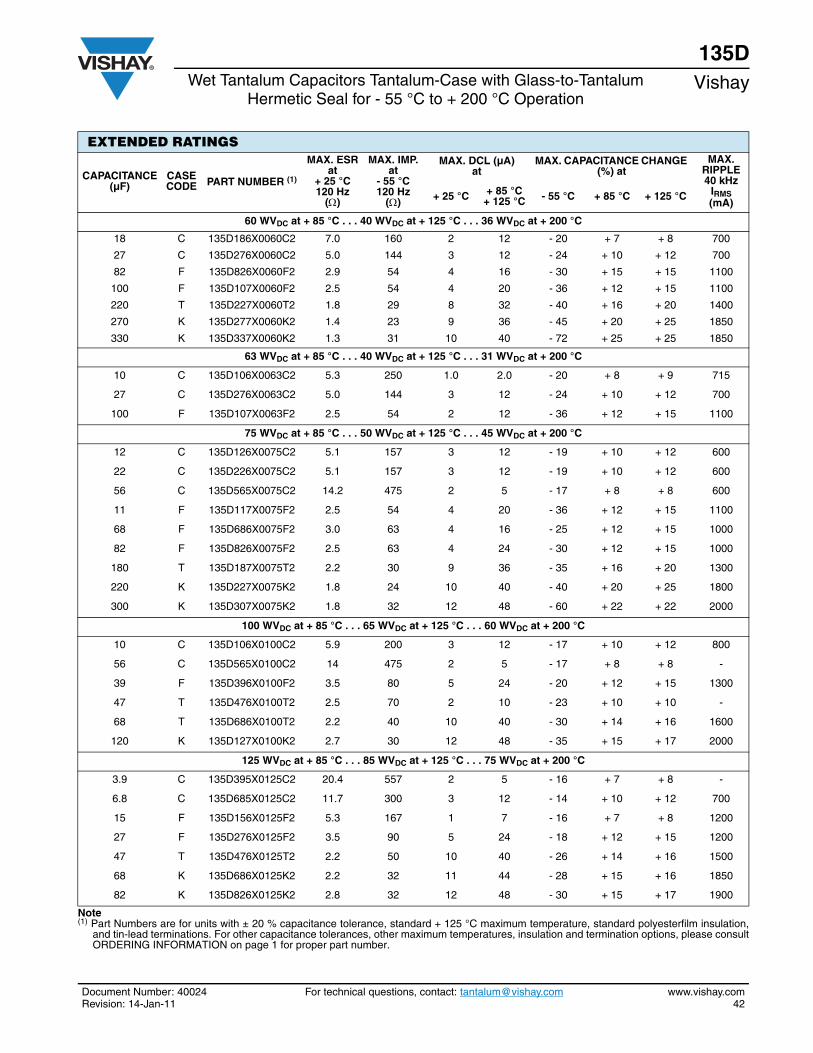
Document Number: 40024 For technical questions, contact: [email protected] www.vishay.comRevision: 14-Jan-11 42
135DWet Tantalum Capacitors Tantalum-Case with Glass-to-Tantalum
Hermetic Seal for - 55 °C to + 200 °C OperationVishay
CAPACITANCE (µF)
CASE CODE PART NUMBER (1)
MAX. ESRat
+ 25 °C 120 Hz
()
MAX. IMP.at
- 55 °C120 Hz
()
MAX. DCL (µA)at
MAX. CAPACITANCE CHANGE (%) at
MAX. RIPPLE 40 kHz
IRMS (mA)
+ 25 °C + 85 °C+ 125 °C - 55 °C + 85 °C + 125 °C
60 WVDC at + 85 °C . . . 40 WVDC at + 125 °C . . . 36 WVDC at + 200 °C
18 C 135D186X0060C2 7.0 160 2 12 - 20 + 7 + 8 700
27 C 135D276X0060C2 5.0 144 3 12 - 24 + 10 + 12 700
82 F 135D826X0060F2 2.9 54 4 16 - 30 + 15 + 15 1100
100 F 135D107X0060F2 2.5 54 4 20 - 36 + 12 + 15 1100
220 T 135D227X0060T2 1.8 29 8 32 - 40 + 16 + 20 1400
270 K 135D277X0060K2 1.4 23 9 36 - 45 + 20 + 25 1850
330 K 135D337X0060K2 1.3 31 10 40 - 72 + 25 + 25 1850
63 WVDC at + 85 °C . . . 40 WVDC at + 125 °C . . . 31 WVDC at + 200 °C
10 C 135D106X0063C2 5.3 250 1.0 2.0 - 20 + 8 + 9 715
27 C 135D276X0063C2 5.0 144 3 12 - 24 + 10 + 12 700
100 F 135D107X0063F2 2.5 54 2 12 - 36 + 12 + 15 1100
75 WVDC at + 85 °C . . . 50 WVDC at + 125 °C . . . 45 WVDC at + 200 °C
12 C 135D126X0075C2 5.1 157 3 12 - 19 + 10 + 12 600
22 C 135D226X0075C2 5.1 157 3 12 - 19 + 10 + 12 600
56 C 135D565X0075C2 14.2 475 2 5 - 17 + 8 + 8 600
11 F 135D117X0075F2 2.5 54 4 20 - 36 + 12 + 15 1100
68 F 135D686X0075F2 3.0 63 4 16 - 25 + 12 + 15 1000
82 F 135D826X0075F2 2.5 63 4 24 - 30 + 12 + 15 1000
180 T 135D187X0075T2 2.2 30 9 36 - 35 + 16 + 20 1300
220 K 135D227X0075K2 1.8 24 10 40 - 40 + 20 + 25 1800
300 K 135D307X0075K2 1.8 32 12 48 - 60 + 22 + 22 2000
100 WVDC at + 85 °C . . . 65 WVDC at + 125 °C . . . 60 WVDC at + 200 °C
10 C 135D106X0100C2 5.9 200 3 12 - 17 + 10 + 12 800
56 C 135D565X0100C2 14 475 2 5 - 17 + 8 + 8 -
39 F 135D396X0100F2 3.5 80 5 24 - 20 + 12 + 15 1300
47 T 135D476X0100T2 2.5 70 2 10 - 23 + 10 + 10 -
68 T 135D686X0100T2 2.2 40 10 40 - 30 + 14 + 16 1600
120 K 135D127X0100K2 2.7 30 12 48 - 35 + 15 + 17 2000
125 WVDC at + 85 °C . . . 85 WVDC at + 125 °C . . . 75 WVDC at + 200 °C
3.9 C 135D395X0125C2 20.4 557 2 5 - 16 + 7 + 8 -
6.8 C 135D685X0125C2 11.7 300 3 12 - 14 + 10 + 12 700
15 F 135D156X0125F2 5.3 167 1 7 - 16 + 7 + 8 1200
27 F 135D276X0125F2 3.5 90 5 24 - 18 + 12 + 15 1200
47 T 135D476X0125T2 2.2 50 10 40 - 26 + 14 + 16 1500
68 K 135D686X0125K2 2.2 32 11 44 - 28 + 15 + 16 1850
82 K 135D826X0125K2 2.8 32 12 48 - 30 + 15 + 17 1900
Note(1) Part Numbers are for units with ± 20 % capacitance tolerance, standard + 125 °C maximum temperature, standard polyesterfilm insulation,
and tin-lead terminations. For other capacitance tolerances, other maximum temperatures, insulation and termination options, please consultORDERING INFORMATION on page 1 for proper part number.
EXTENDED RATINGS
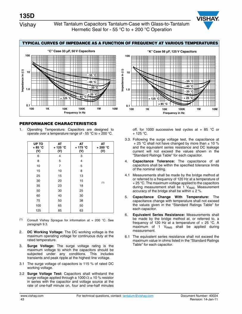
135DVishay Wet Tantalum Capacitors Tantalum-Case with Glass-to-Tantalum
Hermetic Seal for - 55 °C to + 200 °C Operation
www.vishay.com For technical questions, contact: [email protected] Document Number: 4002443 Revision: 14-Jan-11
PERFORMANCE CHARACTERISTICS1. Operating Temperature: Capacitors are designed to
operate over a temperature range of - 55 °C to + 200 °C.
(1) Consult Vishay Sprague for information at + 200 °C. Seeparagraph 9.3.
2. DC Working Voltage: The DC working voltage is themaximum operating voltage for continuous duty at therated temperature.
3. Surge Voltage: The surge voltage rating is themaximum voltage to which the capacitors should besubjected under any conditions. This includestransients and peak ripple at the highest line voltage.
3.1 The surge voltage of capacitors is 115 % of rated DCworking voltage.
3.2 Surge Voltage Test: Capacitors shall withstand thesurge voltage applied through a 1000 ± 10 % resistorin series with the capacitor and voltage source at therate of one-half minute on, four and one-half minutes
off, for 1000 successive test cycles at + 85 °C or+ 125 °C.
3.3. Following the surge voltage test, the capacitance at+ 25 °C shall not have changed by more than ± 10 %and the equivalent series resistance and DC leakagecurrent will not exceed the values shown in the“Standard Ratings Table” for each capacitor.
4. Capacitance Tolerance: The capacitance of allcapacitors shall be within the specified tolerance limitsof the nominal rating.
4.1 Measurements shall be made by the bridge method ator referred to a frequency of 120 Hz at a temperature of+ 25 °C. The maximum voltage applied to the capacitorsduring measurement shall be 1 VRMS. Measurementaccuracy of the bridge shall be within ± 2 %.
5. Capacitance Change With Temperature: Thecapacitance change with temperature shall not exceedthe values given in the “Standard Ratings Table” foreach capacitor.
6. Equivalent Series Resistance: Measurements shallbe made by the bridge method at, or referred to, afrequency of 120 Hz at a temperature of + 25 °C. Amaximum of 1 VRMS shall be applied duringmeasurement.
6.1 The equivalent series resistance shall not exceed themaximum value in ohms listed in the “Standard RatingsTable” for each capacitor.
TYPICAL CURVES OF IMPEDANCE AS A FUNCTION OF FREQUENCY AT VARIOUS TEMPERATURES
0.1
1.0
10
100
100 1K 10K 100K 1M 10M
“C” Case 33 µF, 50 V Capacitors
+ 125 °C+ 25 °C
- 40 °C
- 55 °C
- 20 °C
+ 85 °C
Frequency in Hz
Imp
edan
ce in
(Ω
)
0.1
1.0
10
100
100 1K 10K 100K 1M 10M
“K” Case 56 µF, 125 V Capacitors
- 55 °C
- 40 °C
- 20 °C
+ 125 °C + 25 °C
+ 85 °C
Frequency in Hz
Imp
edan
ce in
(Ω
)
UP TO + 85 °C
(V)
AT + 125 °C
(V)
AT+ 175 °C
(V)
AT + 200 °C
(V)
6 4 3
(1)
8 5 4
10 7 5
15 10 8
25 15 13
30 20 15
35 23 18
50 30 25
60 40 30
75 50 38
100 65 50
125 85 63
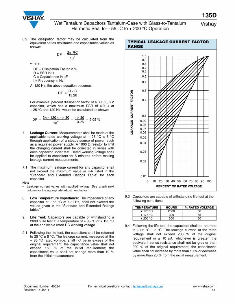
Document Number: 40024 For technical questions, contact: [email protected] www.vishay.comRevision: 14-Jan-11 44
135DWet Tantalum Capacitors Tantalum-Case with Glass-to-Tantalum
Hermetic Seal for - 55 °C to + 200 °C OperationVishay
6.2. The dissipation factor may be calculated from theequivalent series resistance and capacitance values asshown:
where:
DF = Dissipation Factor in %R = ESR in C = Capacitance in µFf = Frequency in Hz
At 120 Hz, the above equation becomes:
For example, percent dissipation factor of a 30 µF, 6 Vcapacitor, which has a maximum ESR of 4.0 at+ 25 °C and 120 Hz, would be calculated as shown:
7. Leakage Current: Measurements shall be made at theapplicable rated working voltage at + 25 °C ± 5 °Cthrough application of a steady source of power, suchas a regulated power supply. A 1000 resistor to limitthe charging current shall be conected in series witheach capacitor under test. Rated working voltage shallbe applied to capacitors for 5 minutes before makingleakage current measurements.
7.1 The maximum leakage current for any capacitor shallnot exceed the maximum value in mA listed in the“Standard and Extended Ratings Table” for eachcapacitor.
Note• Leakage current varies with applied voltage. See graph next
column for the appropriate adjustment factor
8. Low Temperature Impedance: The impedance of anycapacitor at - 55 °C at 120 Hz, shall not exceed thevalues given in the “Standard and Extended Ratingstables”.
9. Life Test: Capacitors are capable of withstanding a2000 h life test at a temperature of + 85 °C or + 125 °Cat the applicable rated DC working voltage.
9.1 Following the life test, the capacitors shall be returnedto 25 °C ± 5 °C. The leakage current, measured at the+ 85 °C rated voltage, shall not be in excess of theoriginal requirement; the capacitance value shall notexceed 150 % of the initial requirement; thecapacitance value shall not change more than 10 %from the initial measurement.
9.3 Capacitors are capable of withstanding life test at the following conditions:
9.4 Following the life test, the capacitors shall be returnedto + 25 °C ± 5 °C. The leakage current, at the ratedvoltage shall not exceed 200 % of the originalrequirement or ± 10 µA, whichever is greater; theequivalent series resistance shall not be greater than200 % of the original requirement; the capacitancevalue shall not increase by more than 10 % or decreaseby more than 20 % from the initial measurement.
DF 2fRC
104------------------=
DF R C13.26---------------=
DF 2 120 4 30
104--------------------------------------------- 4 30
13.26---------------- 9.05 %= = =
TYPICAL LEAKAGE CURRENT FACTOR RANGE
TEMPERATURE HOURS % RATED VOLTAGE+ 175 °C 2000 50+ 175 °C 300 65+ 200 °C 300 60
0 10 20 30 40 50 60 90 10070 80
1.00.90.8
0.6
0.5
0.7
0.4
0.3
0.2
0.090.08
0.06
0.05
0.07
0.04
0.03
0.02
0.1
0.01
LE
AK
AG
E C
UR
RE
NT
FA
CTO
R
PERCENT OF RATED VOLTAGE
135DVishay Wet Tantalum Capacitors Tantalum-Case with Glass-to-Tantalum
Hermetic Seal for - 55 °C to + 200 °C Operation
www.vishay.com For technical questions, contact: [email protected] Document Number: 4002445 Revision: 14-Jan-11
10. Ripple Life Test at + 85 °C: Capacitors shall be testedin accordance with Military Specification MIL-C-39006except that:a) Operation Conditions: This test shall be run at a
frequency of 40 kHz ± 2 kHz sinusoidal and at the RMS ripple current levels specified in the “Standard and Extended Ratings Table”.
b) Applied DC voltage shall be reduced so that thepeak AC voltage plus DC voltage shall not exceedthe rated voltage of the capacitor in either theforward or reverse direction.
10.1 When tested as specified above, capacitors shall meetthe following requirements:a) The DC leakage current at + 25 °C and at + 85 °C
shall not exceed the original requirements.b) The capacitance shall not change more than ± 15 %
from the initial measured value.c) The dissipation factor shall not exceed the original
requirements.
d) Visual examination: There shall be no damage, obliteration of marking or leakage of electrolyte.
11. Reverse Voltage Test: Capcitors shall withstand areverse voltage of 3 VDC at + 85 °C or 2 V at + 125 °Cfor 2000 h. The capacitors shall then be restabilized for24 h at 85 °C with rated DC forward potential appliedthrough a 1000 resistor.
11.1 Following the reverse voltage test, the DC leakagecurrent shall not be in excess of the originalrequirement; the equivalent series resistance shall notexceed 200 % of the initial requirement; thecapacitance value shall not be less than 90 % of theinitial measurement.
12. Mechanical Shock Test: Capacitors shall withstand ashock of 500 g when tested in accordance with method213 of MIL-STD-202, test condition D.
12.1 Following the mechanical shock test, capacitors shallbe examined for evidence of mechanical damage andleakage of electrolyte. Capacitance, equivalent seriesresistance, and DC leakage current shall meet the initialrequirements.
13. High Frequency Vibration: Capacitors shall withstandvibration from 10 Hz to 2000 Hz at 80 g without internaldamage when tested in accordance with MIL-STD-202,method 204, test condition H. Electrical measurementsmade while under these conditions shall show nointermittent contacts, open circuits or short circuits.
13.1 Capacitors shall be securely fastened by means ofsuitable component clips or brackets.
14. Random Vibration: Capacitors shall withstand randomvibration at all levels up to 51 g RMS overall whentested in accordance with MIL-STD-202, method 214,test condition II K. The test shall be conducted for 1.5 hin each of three mutually perpenticular directions.
14.1 Electrical measurements made during the test shallshow no intermittent contacts. open circuits or shortcircuits.
15. Pull Test: Leads shall withstand a tensile stress of3 lbs. (1.4 kg) for 30 s applied axially in accordance withMIL-STD-202, method 211, test condition A.
16. Lead Bend Test: Leads shall meet the bend testspecified in Military Standard MIL-STD-202, method211 A, condition C except that the number of bendsshall be 4.
17. Moisture Resistance: Capacitors shall withstand themoisture resistance cycling test specified in MilitaryStandard MIL-STD-202, method 106, without departurefrom the original limits of capacitance, equivalent seriesresistance and DC leakage current.
18. Reduced Pressure: Capcitors shall be stabilized at areduced atmospheric pressure of 0.82" [20.83 mm] ofmercury for a period of 5 min. Rated DC voltage shall beapplied for 1 min. Capacitors shall not flash over norshall end seals be damaged by this nor should thecapacitors be electrically effected insofar ascapacitance, equivalent series resistance or leakagecurrent is concerned.
19. Seal Test:
19.1 Capacitors shall be tested in accordance withMIL-STD-202, method 112, test condition C, procedureIIIa. Specimens shall be pressurized at 4 atmospheres(gage) for 4 h.
20. Thermal shock: Capacitors shall be subjected to 300cycles of thermal shock in accordance with Militaryspecification MIL-C-39006.
20.1 Following the thermal shock test, capacitor leakagecurrent shall not exceed twice the initial requirement.
21. Marking: Capacitors shall be marked with Sprague, theSprague type (135D); rated capacitance and tolerance(the tolerance shall be coded, using the list shown inHow to Order); rated DC working voltage at + 85 °C;the standard EIA date code of manufacture.
21.1 Polarity shall be indicated by plus signs (+) adjacent to the positive terminal.

Document Number: 40024 For technical questions, contact: [email protected] www.vishay.comRevision: 14-Jan-11 46
135DWet Tantalum Capacitors Tantalum-Case with Glass-to-Tantalum
Hermetic Seal for - 55 °C to + 200 °C OperationVishay
GUIDE TO APPLICATION
1. AC Ripple Current: Subjecting a capacitor to an ACvoltage causes an AC current to flow through it. Theamplitude of the current is dependent on theimpedance of the capacitor at the frequency of theapplied signal:
where:I = Ripple currentV = Applied AC voltageZ = Impedance of capacitor (frequency dependent)
This current causes heating in the capacitor because ofI2R losses (R is the equivalent series resistance at theapplied frequency). This heating or power dissipation,is one of the limiting factors of the capacitor’s ripplecurrent rating.
These power dissipation ratings are based on acalculated + 50 °C internal temperature rise in still air.The maximum alowable ripple currents given in the“Standard and Extended Ratings Tables” are based onthese ratings and the maximum equivalent seriesresistance at that frequency.
The relationship is written as follows:
where:
P = Maximum powerI = Maximum ripple currentR = Equivalent series resistance
Therefore:
where:
R is in P is in WI is in ARMS
2. AC Ripple Voltage: In operation, the peak voltageacross the capacitor (DC working voltage plus peakripple voltage) must not exceed the rated workingvoltage of the capacitor. The DC component of theapplied voltage should be sufficiently large to preventpolarity reversal in excess of 3 V at + 85 °C or 2 V at125 °C.
There will be a point at the lower frequency andcapacitance values when the peak AC voltage will bethe limiting factor on the ripple current - not its heatingeffects.
For example:Given a 25 µF, 8 V capacitor in the “C” case code andassuming a ripple current application at a frequencyof 120 Hz, the total maximum allowable peak to peakvoltage at + 25 °C is:
8 VF + 3 VR = 11 Vpp
In order to allow the full swing of 11 Vpp and notexceed rated forward or rated reverse, a DC bias of2.5 V is assumed to be applied.
From the ”Standard Ratings Table”, the maximumripple current at 40 kHz is 0.820 A. Compensating forthe lower frequency from the “Ripple CurrentMultipliers” tables:
IRMS (120 Hz) = 0.820 A x 0.6 = 0.492 ARMS
This current rating is calculated strictly on the basis ofmaximum power dissipation. Now calculate whatimpressed voltage this amount of current will causeacross this capacitor.Assuming a sinusoidal voltage, calculate the ratedpeak to peak current:
where:
ESR = 4 (from “Standard Ratings” table)
Therefore:
and
Therefore, the peak voltage of the capacitor is thelimiting factor for the ripple current and can becalculated as follows:
CASE CODEMAXIMUM PERMISSIBLE
POWER DISSIPATION AT + 25 °C (W) IN FREE AIR
C 1.00F 1.55T 1.75K 1.95
IV
Z=
P I2R=
IP
R=
Ipp IRMS 2 2 0.492 2.828 1.39 App===
Vpp impressed Ipp ZC 120 Hz =
ZC 120Hz ESR 2 (XC(120 Hz)+ 2
=
XC1
2fC
1
2 120 25 10 6– 53.1 = = =
ZC 4 2 53.1 2+ 53.3 ==
Vpp impressed 1.39 App 53.3 =
74.1 Vpp 11 Vpp=
Max Ipp
VCpp allowed ZC
----------------------------------------- 11.0 V53.3 ------------------ 0.206 App===
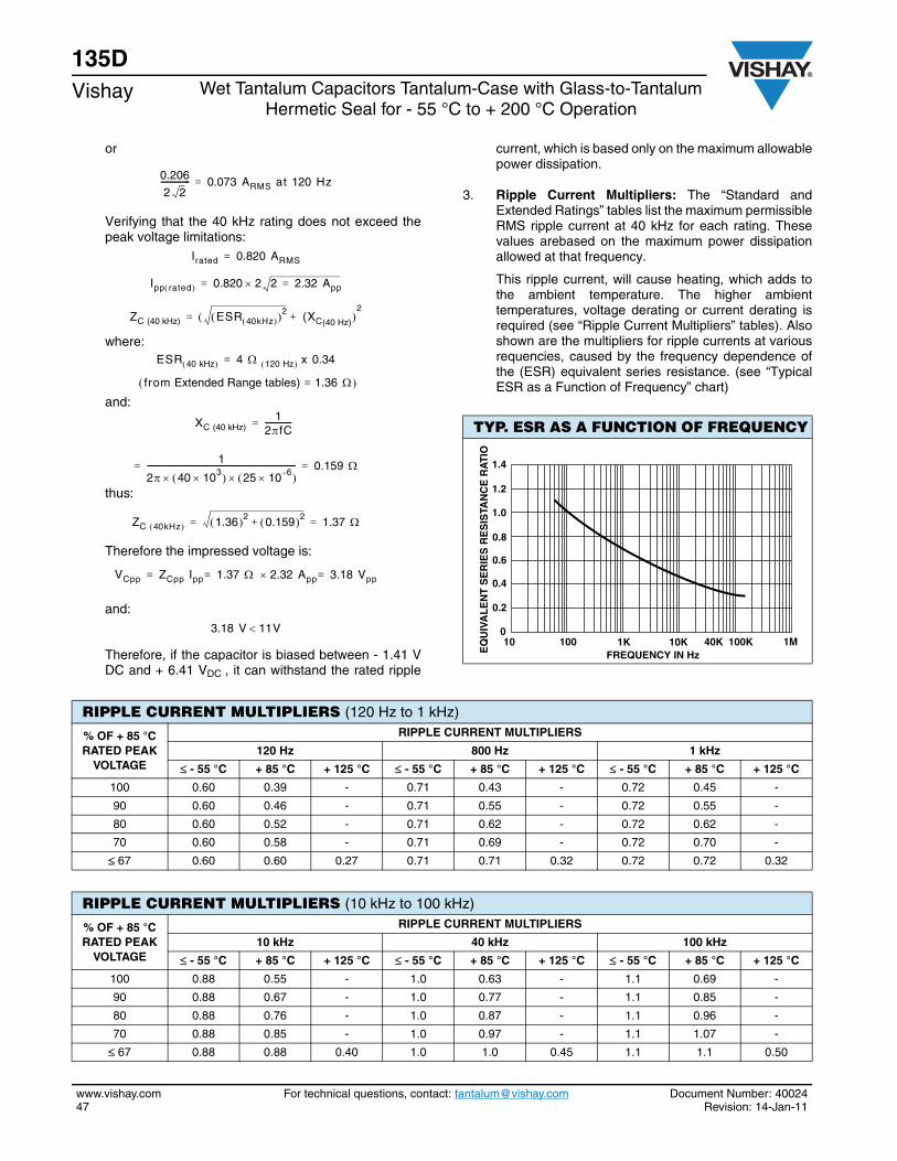
135DVishay Wet Tantalum Capacitors Tantalum-Case with Glass-to-Tantalum
Hermetic Seal for - 55 °C to + 200 °C Operation
www.vishay.com For technical questions, contact: [email protected] Document Number: 4002447 Revision: 14-Jan-11
or
Verifying that the 40 kHz rating does not exceed thepeak voltage limitations:
where:
and:
thus:
Therefore the impressed voltage is:
and:
Therefore, if the capacitor is biased between - 1.41 VDC and + 6.41 VDC , it can withstand the rated ripple
current, which is based only on the maximum allowablepower dissipation.
3. Ripple Current Multipliers: The “Standard andExtended Ratings” tables list the maximum permissibleRMS ripple current at 40 kHz for each rating. Thesevalues arebased on the maximum power dissipationallowed at that frequency.
This ripple current, will cause heating, which adds tothe ambient temperature. The higher ambienttemperatures, voltage derating or current derating isrequired (see “Ripple Current Multipliers” tables). Alsoshown are the multipliers for ripple currents at variousrequencies, caused by the frequency dependence ofthe (ESR) equivalent series resistance. (see “TypicalESR as a Function of Frequency” chart)
0.206
2 2--------------- 0.073 ARMS at 120 Hz=
Irated 0.820 ARMS=
Ipp rated 0.820 2 2 2.32 App==
ZC (40 kHz) ESR 40kHz 2 (XC(40 Hz)+ 2
=
ESR 40 kHz 4 120 Hz x 0.34=
from Extended Range tables) 1.36 =
XC (40 kHz)1
2fC-------------- =
1
2 40 103 25 10 6– ---------------------------------------------------------------------------- 0.159 ==
ZC 40kHz 1.36 2 0.159 2+ 1.37 ==
VCpp ZCpp Ipp 1.37 2.32 App 3.18 Vpp===
3.18 V 11V
TYP. ESR AS A FUNCTION OF FREQUENCY
EQ
UIV
AL
EN
T S
ER
IES
RE
SIS
TAN
CE
RA
TIO
0
0.2
0.6
0.8
0.4
1.4
1.2
1.0
FREQUENCY IN Hz10 100 1K 40K 100K10K 1M
RIPPLE CURRENT MULTIPLIERS (120 Hz to 1 kHz)
% OF + 85 °C RATED PEAK
VOLTAGE
RIPPLE CURRENT MULTIPLIERS
120 Hz 800 Hz 1 kHz
- 55 °C + 85 °C + 125 °C - 55 °C + 85 °C + 125 °C - 55 °C + 85 °C + 125 °C
100 0.60 0.39 - 0.71 0.43 - 0.72 0.45 -
90 0.60 0.46 - 0.71 0.55 - 0.72 0.55 -
80 0.60 0.52 - 0.71 0.62 - 0.72 0.62 -
70 0.60 0.58 - 0.71 0.69 - 0.72 0.70 -
67 0.60 0.60 0.27 0.71 0.71 0.32 0.72 0.72 0.32
RIPPLE CURRENT MULTIPLIERS (10 kHz to 100 kHz)
% OF + 85 °C RATED PEAK
VOLTAGE
RIPPLE CURRENT MULTIPLIERS
10 kHz 40 kHz 100 kHz
- 55 °C + 85 °C + 125 °C - 55 °C + 85 °C + 125 °C - 55 °C + 85 °C + 125 °C
100 0.88 0.55 - 1.0 0.63 - 1.1 0.69 -
90 0.88 0.67 - 1.0 0.77 - 1.1 0.85 -
80 0.88 0.76 - 1.0 0.87 - 1.1 0.96 -
70 0.88 0.85 - 1.0 0.97 - 1.1 1.07 -
67 0.88 0.88 0.40 1.0 1.0 0.45 1.1 1.1 0.50
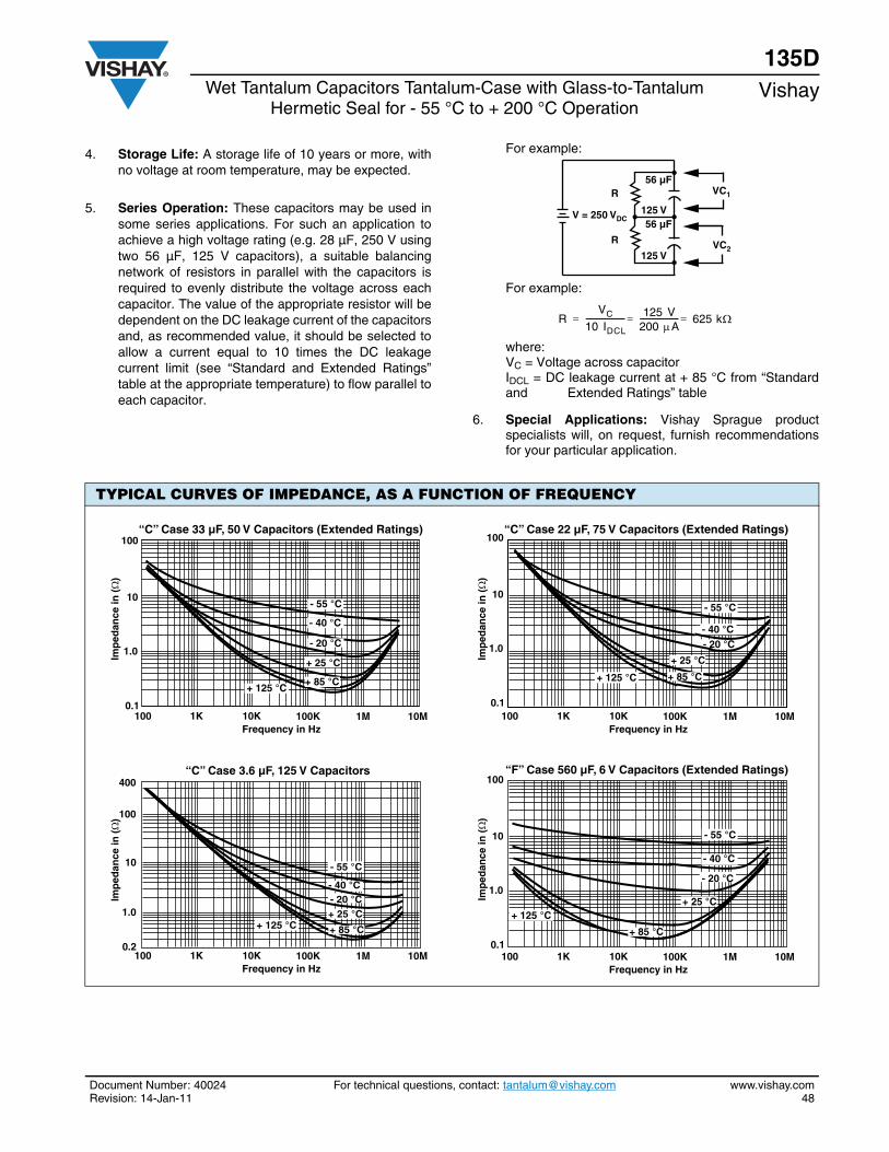
Document Number: 40024 For technical questions, contact: [email protected] www.vishay.comRevision: 14-Jan-11 48
135DWet Tantalum Capacitors Tantalum-Case with Glass-to-Tantalum
Hermetic Seal for - 55 °C to + 200 °C OperationVishay
4. Storage Life: A storage life of 10 years or more, withno voltage at room temperature, may be expected.
5. Series Operation: These capacitors may be used insome series applications. For such an application toachieve a high voltage rating (e.g. 28 µF, 250 V usingtwo 56 µF, 125 V capacitors), a suitable balancingnetwork of resistors in parallel with the capacitors isrequired to evenly distribute the voltage across eachcapacitor. The value of the appropriate resistor will bedependent on the DC leakage current of the capacitorsand, as recommended value, it should be selected toallow a current equal to 10 times the DC leakagecurrent limit (see “Standard and Extended Ratings”table at the appropriate temperature) to flow parallel toeach capacitor.
For example:
For example:
where:VC = Voltage across capacitorIDCL = DC leakage current at + 85 °C from “Standardand Extended Ratings” table
6. Special Applications: Vishay Sprague productspecialists will, on request, furnish recommendationsfor your particular application.
V = 250 VDC
VC1
VC2
56 µF
56 µF125 V
125 V
R
R
RVC
10 IDCL-------------------- 125 V
200 A-------------------- 625 k===
TYPICAL CURVES OF IMPEDANCE, AS A FUNCTION OF FREQUENCY
0.1
10
1.0
100
Frequency in Hz100 1K 100K10K 1M 10M
“C” Case 33 µF, 50 V Capacitors (Extended Ratings)
Imp
edan
ce in
(Ω
)
- 55 °C
- 40 °C
- 20 °C
+ 125 °C
+ 25 °C
+ 85 °C
Frequency in Hz100 1K 100K10K 1M 10M
“C” Case 22 µF, 75 V Capacitors (Extended Ratings)
Imp
edan
ce in
(Ω
)
- 55 °C
- 40 °C- 20 °C
+ 125 °C
+ 25 °C
+ 85 °C
0.1
10
1.0
100
0.2
10
1.0
100
400
Frequency in Hz100 1K 100K10K 1M 10M
“C” Case 3.6 µF, 125 V Capacitors
Imp
edan
ce in
(Ω
)
- 55 °C
- 40 °C- 20 °C
+ 125 °C+ 25 °C
+ 85 °C
Frequency in Hz100 1K 100K10K 1M 10M
“F” Case 560 µF, 6 V Capacitors (Extended Ratings)
Imp
edan
ce in
(Ω
)
- 20 °C
- 55 °C
- 40 °C
+ 25 °C
+ 85 °C
+ 125 °C
0.1
10
1.0
100
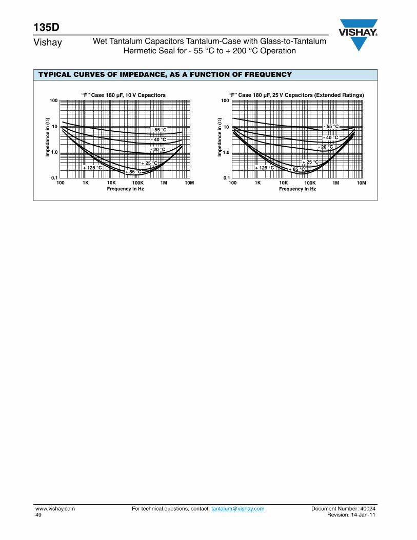
135DVishay Wet Tantalum Capacitors Tantalum-Case with Glass-to-Tantalum
Hermetic Seal for - 55 °C to + 200 °C Operation
www.vishay.com For technical questions, contact: [email protected] Document Number: 4002449 Revision: 14-Jan-11
TYPICAL CURVES OF IMPEDANCE, AS A FUNCTION OF FREQUENCY
0.1
10
1.0
100
Frequency in Hz100 1K 100K10K 1M 10M
“F” Case 180 µF, 10 V Capacitors
Imp
edan
ce in
(Ω
)
+ 25 °C+ 125 °C
- 20 °C
- 55 °C
- 40 °C
+ 85 °C0.1
10
1.0
100
Frequency in Hz100 1K 100K10K 1M 10M
“F” Case 180 µF, 25 V Capacitors (Extended Ratings)
Imp
edan
ce in
(Ω
)
+ 25 °C+ 125 °C
- 20 °C
- 55 °C
- 40 °C
+ 85 °C
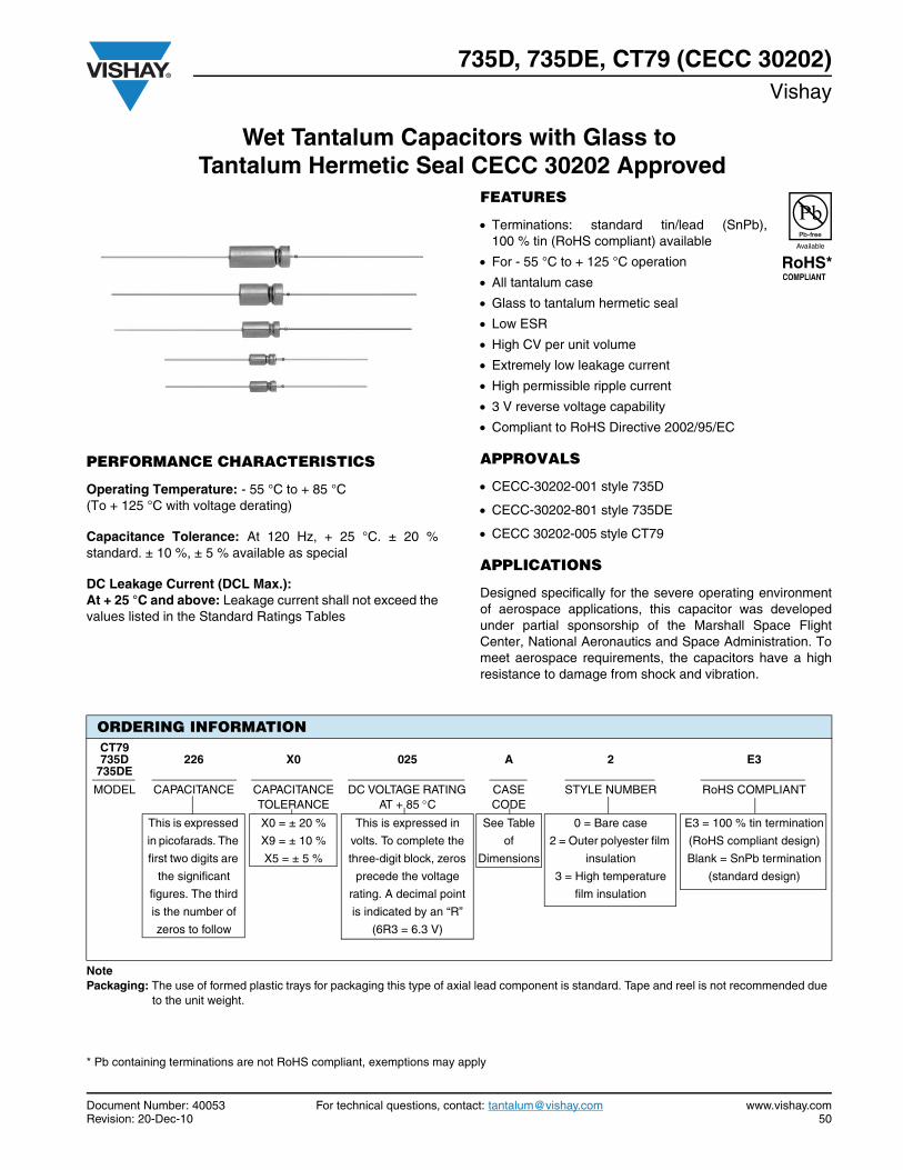
735D, 735DE, CT79 (CECC 30202)Vishay
Document Number: 40053 For technical questions, contact: [email protected] www.vishay.comRevision: 20-Dec-10 50
Wet Tantalum Capacitors with Glass to Tantalum Hermetic Seal CECC 30202 Approved
PERFORMANCE CHARACTERISTICS
Operating Temperature: - 55 °C to + 85 °C(To + 125 °C with voltage derating)
Capacitance Tolerance: At 120 Hz, + 25 °C. ± 20 %standard. ± 10 %, ± 5 % available as special
DC Leakage Current (DCL Max.):At + 25 °C and above: Leakage current shall not exceed thevalues listed in the Standard Ratings Tables
FEATURES
Terminations: standard tin/lead (SnPb),100 % tin (RoHS compliant) available
For - 55 °C to + 125 °C operation
All tantalum case
Glass to tantalum hermetic seal
Low ESR
High CV per unit volume
Extremely low leakage current
High permissible ripple current
3 V reverse voltage capability
Compliant to RoHS Directive 2002/95/EC
APPROVALS
CECC-30202-001 style 735D
CECC-30202-801 style 735DE
CECC 30202-005 style CT79
APPLICATIONS
Designed specifically for the severe operating environmentof aerospace applications, this capacitor was developedunder partial sponsorship of the Marshall Space FlightCenter, National Aeronautics and Space Administration. Tomeet aerospace requirements, the capacitors have a highresistance to damage from shock and vibration.
* Pb containing terminations are not RoHS compliant, exemptions may apply
ORDERING INFORMATIONCT79735D
735DE226 X0 025 A 2 E3
MODEL CAPACITANCE CAPACITANCE TOLERANCE
DC VOLTAGE RATING AT + 85 C
CASE CODE
STYLE NUMBER RoHS COMPLIANT
This is expressed
in picofarads. The
first two digits are
the significant
figures. The third
is the number of
zeros to follow
X0 = ± 20 %
X9 = ± 10 %
X5 = ± 5 %
This is expressed in
volts. To complete the
three-digit block, zeros
precede the voltage
rating. A decimal point
is indicated by an “R”
(6R3 = 6.3 V)
See Table
of
Dimensions
0 = Bare case
2 = Outer polyester film
insulation
3 = High temperature
film insulation
E3 = 100 % tin termination
(RoHS compliant design)
Blank = SnPb termination
(standard design)
Note Packaging: The use of formed plastic trays for packaging this type of axial lead component is standard. Tape and reel is not recommended due
to the unit weight.
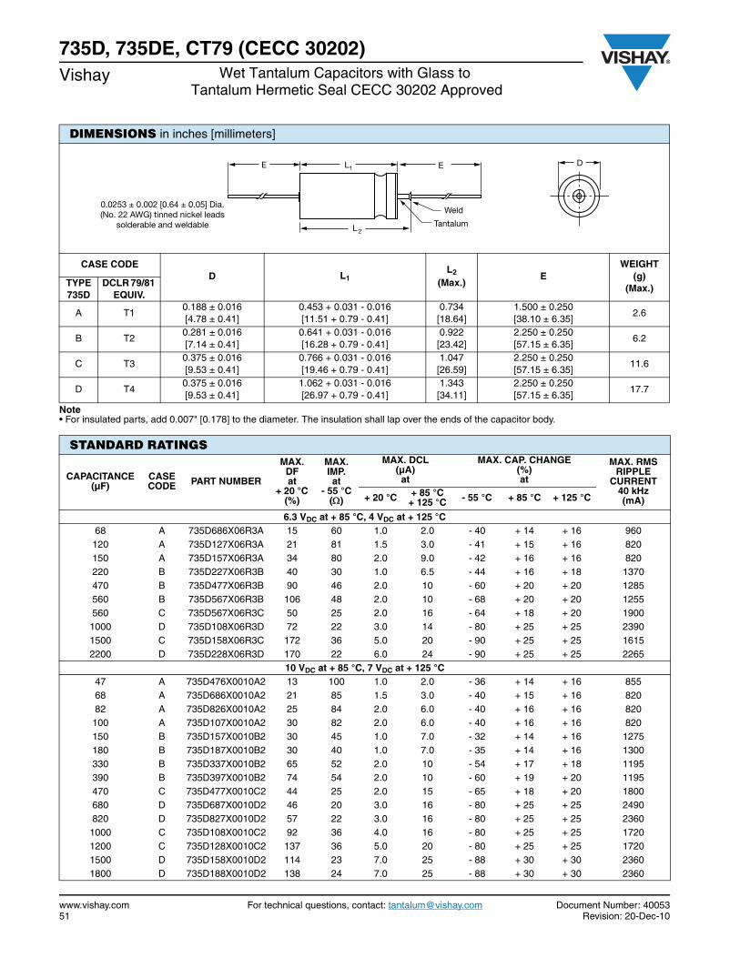
www.vishay.com For technical questions, contact: [email protected] Document Number: 4005351 Revision: 20-Dec-10
735D, 735DE, CT79 (CECC 30202)Vishay Wet Tantalum Capacitors with Glass to
Tantalum Hermetic Seal CECC 30202 Approved
DIMENSIONS in inches [millimeters]
CASE CODE D L1
L2
(Max.) E
WEIGHT (g)
(Max.) TYPE 735D
DCLR 79/81 EQUIV.
A T1 0.188 ± 0.016 [4.78 ± 0.41]
0.453 + 0.031 - 0.016 [11.51 + 0.79 - 0.41]
0.734 [18.64]
1.500 ± 0.250 [38.10 ± 6.35]
2.6
B T2 0.281 ± 0.016 [7.14 ± 0.41]
0.641 + 0.031 - 0.016 [16.28 + 0.79 - 0.41]
0.922 [23.42]
2.250 ± 0.250 [57.15 ± 6.35]
6.2
C T3 0.375 ± 0.016 [9.53 ± 0.41]
0.766 + 0.031 - 0.016 [19.46 + 0.79 - 0.41]
1.047 [26.59]
2.250 ± 0.250[57.15 ± 6.35]
11.6
D T4 0.375 ± 0.016 [9.53 ± 0.41]
1.062 + 0.031 - 0.016 [26.97 + 0.79 - 0.41]
1.343 [34.11]
2.250 ± 0.250[57.15 ± 6.35]
17.7
Note• For insulated parts, add 0.007" [0.178] to the diameter. The insulation shall lap over the ends of the capacitor body.
DE E
L2
L1
Tantalum
Weld0.0253 ± 0.002 [0.64 ± 0.05] Dia.(No. 22 AWG) tinned nickel leads
solderable and weldable
STANDARD RATINGS
CAPACITANCE (µF)
CASE CODE PART NUMBER
MAX. DFat
+ 20 °C (%)
MAX. IMP.at
- 55 °C()
MAX. DCL (µA) at
MAX. CAP. CHANGE (%) at
MAX. RMS RIPPLE
CURRENT40 kHz(mA)+ 20 °C + 85 °C
+ 125 °C - 55 °C + 85 °C + 125 °C
6.3 VDC at + 85 °C, 4 VDC at + 125 °C68 A 735D686X06R3A 15 60 1.0 2.0 - 40 + 14 + 16 960 120 A 735D127X06R3A 21 81 1.5 3.0 - 41 + 15 + 16 820 150 A 735D157X06R3A 34 80 2.0 9.0 - 42 + 16 + 16 820 220 B 735D227X06R3B 40 30 1.0 6.5 - 44 + 16 + 18 1370 470 B 735D477X06R3B 90 46 2.0 10 - 60 + 20 + 20 1285 560 B 735D567X06R3B 106 48 2.0 10 - 68 + 20 + 20 1255 560 C 735D567X06R3C 50 25 2.0 16 - 64 + 18 + 20 1900 1000 D 735D108X06R3D 72 22 3.0 14 - 80 + 25 + 25 2390 1500 C 735D158X06R3C 172 36 5.0 20 - 90 + 25 + 25 1615 2200 D 735D228X06R3D 170 22 6.0 24 - 90 + 25 + 25 2265
10 VDC at + 85 °C, 7 VDC at + 125 °C47 A 735D476X0010A2 13 100 1.0 2.0 - 36 + 14 + 16 855 68 A 735D686X0010A2 21 85 1.5 3.0 - 40 + 15 + 16 820 82 A 735D826X0010A2 25 84 2.0 6.0 - 40 + 16 + 16 820 100 A 735D107X0010A2 30 82 2.0 6.0 - 40 + 16 + 16 820 150 B 735D157X0010B2 30 45 1.0 7.0 - 32 + 14 + 16 1275 180 B 735D187X0010B2 30 40 1.0 7.0 - 35 + 14 + 16 1300 330 B 735D337X0010B2 65 52 2.0 10 - 54 + 17 + 18 1195 390 B 735D397X0010B2 74 54 2.0 10 - 60 + 19 + 20 1195 470 C 735D477X0010C2 44 25 2.0 15 - 65 + 18 + 20 1800 680 D 735D687X0010D2 46 20 3.0 16 - 80 + 25 + 25 2490 820 D 735D827X0010D2 57 22 3.0 16 - 80 + 25 + 25 2360 1000 C 735D108X0010C2 92 36 4.0 16 - 80 + 25 + 25 1720 1200 C 735D128X0010C2 137 36 5.0 20 - 80 + 25 + 25 1720 1500 D 735D158X0010D2 114 23 7.0 25 - 88 + 30 + 30 2360 1800 D 735D188X0010D2 138 24 7.0 25 - 88 + 30 + 30 2360
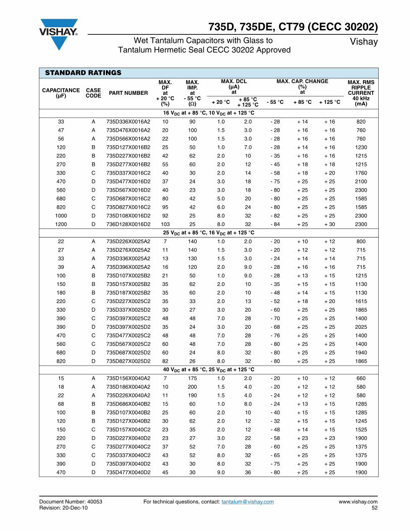
Document Number: 40053 For technical questions, contact: [email protected] www.vishay.comRevision: 20-Dec-10 52
735D, 735DE, CT79 (CECC 30202)Wet Tantalum Capacitors with Glass to
Tantalum Hermetic Seal CECC 30202 ApprovedVishay
STANDARD RATINGS
CAPACITANCE (µF)
CASE CODE PART NUMBER
MAX. DFat
+ 20 °C (%)
MAX. IMP.at
- 55 °C()
MAX. DCL (µA) at
MAX. CAP. CHANGE (%) at
MAX. RMS RIPPLE
CURRENT40 kHz(mA)+ 20 °C + 85 °C
+ 125 °C - 55 °C + 85 °C + 125 °C
16 VDC at + 85 °C, 10 VDC at + 125 °C
33 A 735D336X0016A2 10 90 1.0 2.0 - 28 + 14 + 16 820
47 A 735D476X0016A2 20 100 1.5 3.0 - 28 + 16 + 16 760
56 A 735D566X0016A2 22 100 1.5 3.0 - 28 + 16 + 16 760
120 B 735D127X0016B2 25 50 1.0 7.0 - 28 + 14 + 16 1230
220 B 735D227X0016B2 42 62 2.0 10 - 35 + 16 + 16 1215
270 B 735D277X0016B2 55 60 2.0 12 - 45 + 18 + 18 1215
330 C 735D337X0016C2 40 30 2.0 14 - 58 + 18 + 20 1760
470 D 735D477X0016D2 37 24 3.0 18 - 75 + 25 + 25 2100
560 D 735D567X0016D2 40 23 3.0 18 - 80 + 25 + 25 2300
680 C 735D687X0016C2 80 42 5.0 20 - 80 + 25 + 25 1585
820 C 735D827X0016C2 95 42 6.0 24 - 80 + 25 + 25 1585
1000 D 735D108X0016D2 92 25 8.0 32 - 82 + 25 + 25 2300
1200 D 736D128X0016D2 103 25 8.0 32 - 84 + 25 + 30 2300
25 VDC at + 85 °C, 16 VDC at + 125 °C
22 A 735D226X0025A2 7 140 1.0 2.0 - 20 + 10 + 12 800
27 A 735D276X0025A2 11 140 1.5 3.0 - 20 + 12 + 12 715
33 A 735D336X0025A2 13 130 1.5 3.0 - 24 + 14 + 14 715
39 A 735D396X0025A2 16 120 2.0 9.0 - 28 + 16 + 16 715
100 B 735D107X0025B2 21 50 1.0 9.0 - 28 + 13 + 15 1215
150 B 735D157X0025B2 35 62 2.0 10 - 35 + 15 + 15 1130
180 B 735D187X0025B2 35 60 2.0 10 - 48 + 14 + 15 1130
220 C 735D227X0025C2 35 33 2.0 13 - 52 + 18 + 20 1615
330 D 735D337X0025D2 30 27 3.0 20 - 60 + 25 + 25 1865
390 C 735D397X0025C2 48 48 7.0 28 - 70 + 25 + 25 1400
390 D 735D397X0025D2 35 24 3.0 20 - 68 + 25 + 25 2025
470 C 735D477X0025C2 48 48 7.0 28 - 76 + 25 + 25 1400
560 C 735D567X0025C2 60 48 7.0 28 - 80 + 25 + 25 1400
680 D 735D687X0025D2 60 24 8.0 32 - 80 + 25 + 25 1940
820 D 735D827X0025D2 82 26 8.0 32 - 80 + 25 + 25 1865
40 VDC at + 85 °C, 25 VDC at + 125 °C
15 A 735D156X0040A2 7 175 1.0 2.0 - 20 + 10 + 12 660
18 A 735D186X0040A2 10 200 1.5 4.0 - 20 + 12 + 12 580
22 A 735D226X0040A2 11 190 1.5 4.0 - 24 + 12 + 12 580
68 B 735D686X0040B2 15 60 1.0 8.0 - 24 + 13 + 15 1285
100 B 735D107X0040B2 25 60 2.0 10 - 40 + 15 + 15 1285
120 B 735D127X0040B2 30 62 2.0 12 - 32 + 15 + 15 1245
150 C 735D157X0040C2 23 35 2.0 12 - 48 + 14 + 15 1525
220 D 735D227X0040D2 23 27 3.0 22 - 58 + 23 + 23 1900
270 C 735D277X0040C2 37 52 7.0 28 - 60 + 25 + 25 1375
330 C 735D337X0040C2 43 52 8.0 32 - 65 + 25 + 25 1375
390 D 735D397X0040D2 43 30 8.0 32 - 75 + 25 + 25 1900
470 D 735D477X0040D2 45 30 9.0 36 - 80 + 25 + 25 1900

www.vishay.com For technical questions, contact: [email protected] Document Number: 4005353 Revision: 20-Dec-10
735D, 735DE, CT79 (CECC 30202)Vishay Wet Tantalum Capacitors with Glass to
Tantalum Hermetic Seal CECC 30202 Approved
STANDARD RATINGS
CAPACITANCE (µF)
CASE CODE PART NUMBER
MAX. DFat
+ 20 °C (%)
MAX. IMP.at
- 55 °C()
MAX. DCL (µA) at
MAX. CAP. CHANGE (%) at
MAX. RMS RIPPLE
CURRENT40 kHz (mA)+ 20 °C + 85 °C
+ 125 °C - 55 °C + 85 °C + 125 °C
63 VDC at + 85 °C, 40VDC at + 125 °C10 A 735D106X0063A2 4 250 1.0 2.0 - 20 + 8 + 9 575 12 A 735D126X0063A2 7 233 2.0 4.0 - 20 + 8 + 9 575 15 A 735D156X0063A2 8 220 2.0 9.0 - 22 + 9 + 9 565 47 B 735D476X0063B2 13 70 1.0 9.0 - 24 + 13 + 15 1150 56 B 735D566X0063B2 18 72 2.0 12 - 26 + 14 + 15 1150 82 B 735D826X0063B2 22 70 2.0 12 - 36 + 15 + 15 1150 100 C 735D107X0063C2 18 42 2.0 11 - 37 + 14 + 15 1420 120 C 735D127X0063C2 20 49 3.0 18 - 40 + 18 + 18 1420 150 D 735D157X0063D2 17 27 3.0 22 - 45 + 20 + 20 1865 220 C 735D227X0063C2 37 55 8.0 32 - 50 + 25 + 25 1345 270 D 735D277X0063D2 26 33 9.0 36 - 70 + 24 + 25 1850 330 D 735D337X0063D2 32 31 10 40 - 72 + 25 + 25 1850
75 VDC at + 85 °C, 50 VDC at + 125 °C6.8 A 735D685X0075A2 3 300 1.0 2.0 - 20 + 8 + 9 610 8.2 A 735D825X0075A2 6 280 1.5 3.0 - 22 + 9 + 9 610 33 B 735D336X0075B2 10 90 1.0 9.0 - 24 + 10 + 12 1079 47 B 735D476X0075B2 15 87 2.0 10 - 30 + 14 + 14 1055 68 B 735D686X0075B2 21 86 2.0 12 - 36 + 15 + 15 1055 68 C 735D686X0075C2 13 50 2.0 10 - 30 + 14 + 15 1525 82 C 735D826X0075C2 15 45 2.0 10 - 32 + 15 + 15 1335 100 C 735D107X0075C2 19 60 8.0 32 - 36 + 17 + 18 1335 120 D 735D127X0075D2 12 28 3.0 24 - 36 + 20 + 20 1915 150 C 735D157X0075C2 25 60 9.0 36 - 40 + 20 + 20 1335 150 D 735D157X0075D2 17 30 9.0 36 - 48 + 21 + 22 1915 180 C 735D187X0075C2 28 60 9.0 36 - 50 + 22 + 22 1335 220 D 735D227X0075D2 37 32 10 40 - 60 + 22 + 22 1850
100 VDC at + 85 °C, 70 VDC at + 125 °C 4.7 A 735D475X0100A2 3 500 1.0 2.0 - 16 + 7 + 8 565 5.6 A 735D565X0100A2 6 475 2.0 5.0 - 17 + 8 + 8 530 22 B 735D226X0100B2 8 100 1.0 9.0 - 16 + 8 + 8 1065 33 B 735D336X0100B2 14 95 3.0 15 - 16 + 8 + 8 1065 33 C 735D336X0100C2 7 93 2.0 10 - 16 + 8 + 8 1200 39 B 735D396X0100B2 10 92 2.0 12 - 24 + 12 + 12 1065 39 C 735D396X0100C2 8 90 2.0 10 - 16 + 8 + 8 1285 47 C 735D476X0100C2 9 70 2.0 10 - 23 + 10 + 10 1390 56 C 735D566X0100C2 11 60 2.0 10 - 28 + 14 + 15 1335 68 C 735D686X0100C2 15 60 10 40 - 30 + 15 + 15 1335 68 D 735D686X0100D2 8 42 3.0 26 - 24 + 15 + 15 1860 82 D 735D826X0100D2 10 39 3.0 24 - 24 + 18 + 18 1860 100 D 735D107X0100D2 11 36 3.0 24 - 35 + 20 + 20 1860
125 VDC at + 85 °C, 85 VDC at + 125 °C 2.7 A 735D275X0125A2 3 780 1.0 2.0 - 16 + 7 + 8 455 3.3 A 735D335X0125A2 3 600 1.0 2.0 - 16 + 7 + 8 495 3.9 A 735D395X0125A2 3.5 557 2.0 5.0 - 16 + 8 + 8 495 15 B 735D156X0125B2 6 167 1.0 7.0 - 16 + 7 + 8 1050 18 B 735D186X0125B2 8 133 2.0 10 - 16 + 8 + 8 1065 39 C 735D396X0125C2 8 90 2.0 10 - 16 + 8 + 8 1285 47 C 735D476X0125C2 9 70 2.0 10 - 23 + 10 + 10 1285 68 D 735D686X0125D2 8 42 3.0 26 - 24 + 15 + 15 1860 82 D 735D826X0125D2 10 39 3.0 24 - 24 + 18 + 18 1860
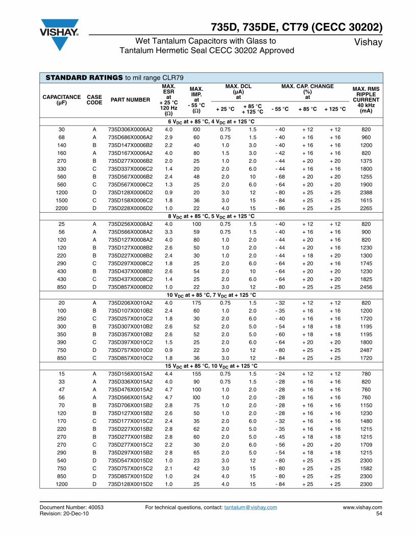
Document Number: 40053 For technical questions, contact: [email protected] www.vishay.comRevision: 20-Dec-10 54
735D, 735DE, CT79 (CECC 30202)Wet Tantalum Capacitors with Glass to
Tantalum Hermetic Seal CECC 30202 ApprovedVishay
STANDARD RATINGS to mil range CLR79
CAPACITANCE (µF)
CASE CODE PART NUMBER
MAX. ESR
at + 25 °C120 Hz
()
MAX. IMP.at
- 55 °C()
MAX. DCL (µA) at
MAX. CAP. CHANGE (%) at
MAX. RMS RIPPLE
CURRENT40 kHz (mA)+ 25 °C + 85 °C
+ 125 °C - 55 °C + 85 °C + 125 °C
6 VDC at + 85 °C, 4 VDC at + 125 °C30 A 735D306X0006A2 4.0 l00 0.75 1.5 - 40 + 12 + 12 820
68 A 735D686X0006A2 2.9 60 0.75 1.5 - 40 + 16 + 16 960
140 B 735D147X0006B2 2.2 40 1.0 3.0 - 40 + 16 + 16 1200
160 A 735D167X0006A2 4.0 80 1.5 3.0 - 42 + 16 + 16 820
270 B 735D277X0006B2 2.0 25 1.0 2.0 - 44 + 20 + 20 1375
330 C 735D337X0006C2 1.4 20 2.0 6.0 - 44 + 16 + 16 1800
560 B 735D567X0006B2 2.4 48 2.0 10 - 68 + 20 + 20 1255
560 C 735D567X0006C2 1.3 25 2.0 6.0 - 64 + 20 + 20 1900
1200 D 735D128X0006D2 0.9 20 3.0 12 - 80 + 25 + 25 2388
1500 C 735D158X0006C2 1.8 36 3.0 15 - 84 + 25 + 25 1615
2200 D 735D228X0006D2 1.0 22 4.0 15 - 86 + 25 + 25 2265
8 VDC at + 85 °C, 5 VDC at + 125 °C25 A 735D256X0008A2 4.0 100 0.75 1.5 - 40 + 12 + 12 820
56 A 735D566X0008A2 3.3 59 0.75 1.5 - 40 + 16 + 16 900
120 A 735D127X0008A2 4.0 80 1.0 2.0 - 44 + 20 + 16 820
120 B 735D127X0008B2 2.6 50 1.0 2.0 - 44 + 20 + 16 1230
220 B 735D227X0008B2 2.4 30 1.0 2.0 - 44 + 18 + 20 1300
290 C 735D297X0008C2 1.8 25 2.0 6.0 - 64 + 20 + 16 1745
430 B 735D437X0008B2 2.6 54 2.0 10 - 64 + 20 + 20 1230
430 C 735D437X0008C2 1.4 25 2.0 6.0 - 64 + 20 + 20 1825
850 D 735D857X0008D2 1.0 22 3.0 12 - 80 + 25 + 25 2456
10 VDC at + 85 °C, 7 VDC at + 125 °C 20 A 735D206X0010A2 4.0 175 0.75 1.5 - 32 + 12 + 12 820
100 B 735D107X0010B2 2.4 60 1.0 2.0 - 35 + 16 + 16 1200
250 C 735D257X0010C2 1.8 30 2.0 6.0 - 40 + 16 + 16 1720
300 B 735D307X0010B2 2.6 52 2.0 5.0 - 54 + 18 + 18 1195
350 B 735D357X0010B2 2.6 52 2.0 5.0 - 60 + 18 + 18 1195
390 C 735D397X0010C2 1.5 25 2.0 6.0 - 64 + 20 + 20 1800
750 D 735D757X0010D2 0.9 22 3.0 12 - 80 + 25 + 25 2487
850 C 735D857X0010C2 1.8 36 3.0 12 - 84 + 25 + 25 1720
15 VDC at + 85 °C, 10 VDC at + 125 °C15 A 735D156X0015A2 4.4 155 0.75 1.5 - 24 + 12 + 12 780
33 A 735D336X0015A2 4.0 90 0.75 1.5 - 28 + 16 + 16 820
47 A 735D476X0015A2 4.7 100 1.0 2.0 - 28 + 16 + 16 760
56 A 735D566X0015A2 4.7 l00 1.0 2.0 - 28 + 16 + 16 760
70 B 735D706X0015B2 2.8 75 1.0 2.0 - 28 + 16 + 16 1150
120 B 735D127X0015B2 2.6 50 1.0 2.0 - 28 + 16 + 16 1230
170 C 735D177X0015C2 2.4 35 2.0 6.0 - 32 + 16 + 16 1480
220 B 735D227X0015B2 2.8 62 2.0 5.0 - 35 + 16 + 16 1215
270 B 735D277X0015B2 2.8 60 2.0 5.0 - 45 + 18 + 18 1215
270 C 735D277X0015C2 2.2 30 2.0 6.0 - 56 + 20 + 20 1709
290 B 735D297X0015B2 2 8 65 2.0 5.0 - 54 + 18 + 18 1215
540 D 735D547X0015D2 1.0 23 3.0 12 - 80 + 25 + 25 2300
750 C 735D757X0015C2 2.1 42 3.0 15 - 80 + 25 + 25 1582
850 D 735D857X0015D2 1.0 24 4.0 15 - 80 + 25 + 25 2300
1200 D 735D128X0015D2 1.0 25 4.0 15 - 84 + 25 + 25 2300
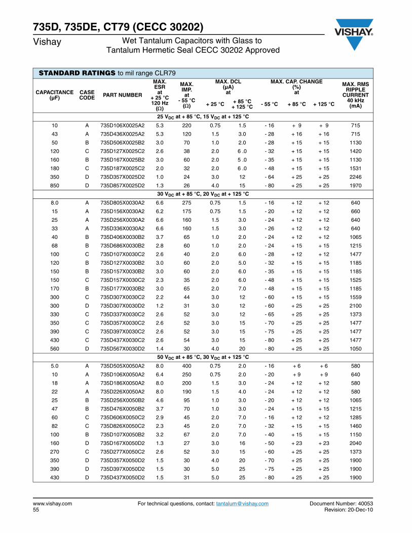
www.vishay.com For technical questions, contact: [email protected] Document Number: 4005355 Revision: 20-Dec-10
735D, 735DE, CT79 (CECC 30202)Vishay Wet Tantalum Capacitors with Glass to
Tantalum Hermetic Seal CECC 30202 Approved
STANDARD RATINGS to mil range CLR79
CAPACITANCE (µF)
CASE CODE PART NUMBER
MAX. ESR
at + 25 °C120 Hz
()
MAX. IMP.at
- 55 °C()
MAX. DCL (µA) at
MAX. CAP. CHANGE (%) at
MAX. RMS RIPPLE
CURRENT40 kHz(mA)+ 25 °C + 85 °C
+ 125 °C - 55 °C + 85 °C + 125 °C
25 VDC at + 85 °C, 15 VDC at + 125 °C
10 A 735D106X0025A2 5.3 220 0.75 1.5 - 16 + 9 + 9 715
43 A 735D436X0025A2 5.3 120 1.5 3.0 - 28 + 16 + 16 715
50 B 735D506X0025B2 3.0 70 1.0 2.0 - 28 + 15 + 15 1130
120 C 735D127X0025C2 2.6 38 2.0 6 .0 - 32 + 15 + 15 1420
160 B 735D167X0025B2 3.0 60 2.0 5 .0 - 35 + 15 + 15 1130
180 C 735D187X0025C2 2.0 32 2.0 6 .0 - 48 + 15 + 15 1531
350 D 735D357X0025D2 1.0 24 3.0 12 - 64 + 25 + 25 2246
850 D 735D857X0025D2 1.3 26 4.0 15 - 80 + 25 + 25 1970
30 VDC at + 85 °C, 20 VDC at + 125 °C
8.0 A 735D805X0030A2 6.6 275 0.75 1.5 - 16 + 12 + 12 640
15 A 735D156X0030A2 6.2 175 0.75 1.5 - 20 + 12 + 12 660
25 A 735D256X0030A2 6.6 160 1.5 3.0 - 24 + 12 + 12 640
33 A 735D336X0030A2 6.6 160 1.5 3.0 - 26 + 12 + 12 640
40 B 735D406X0030B2 3.7 65 1.0 2.0 - 24 + 12 + 12 1065
68 B 735D686X0030B2 2.8 60 1.0 2.0 - 24 + 15 + 15 1215
100 C 735D107X0030C2 2.6 40 2.0 6.0 - 28 + 12 + 12 1477
120 B 735D127X0030B2 3.0 60 2.0 5.0 - 32 + 15 + 15 1185
150 B 735D157X0030B2 3.0 60 2.0 6.0 - 35 + 15 + 15 1185
150 C 735D157X0030C2 2.3 35 2.0 6.0 - 48 + 15 + 15 1525
170 B 735D177X0030B2 3.0 65 2.0 7.0 - 48 + 15 + 15 1185
300 C 735D307X0030C2 2.2 44 3.0 12 - 60 + 15 + 15 1559
300 D 735D307X0030D2 1.2 31 3.0 12 - 60 + 25 + 25 2100
330 C 735D337X0030C2 2.6 52 3.0 12 - 65 + 25 + 25 1373
350 C 735D357X0030C2 2.6 52 3.0 15 - 70 + 25 + 25 1477
390 C 735D397X0030C2 2.6 52 3.0 15 - 75 + 25 + 25 1477
430 C 735D437X0030C2 2.6 54 3.0 15 - 80 + 25 + 25 1477
560 D 735D567X0030D2 1.4 30 4.0 20 - 80 + 25 + 25 1050
50 VDC at + 85 °C, 30 VDC at + 125 °C
5.0 A 735D505X0050A2 8.0 400 0.75 2.0 - 16 + 6 + 6 580
10 A 735D106X0050A2 6.4 250 0.75 2.0 - 20 + 9 + 9 640
18 A 735D186X0050A2 8.0 200 1.5 3.0 - 24 + 12 + 12 580
22 A 735D226X0050A2 8.0 190 1.5 4.0 - 24 + 12 + 12 580
25 B 735D256X0050B2 4.6 95 1.0 3.0 - 20 + 12 + 12 1065
47 B 735D476X0050B2 3.7 70 1.0 3.0 - 24 + 15 + 15 1215
60 C 735D606X0050C2 2.9 45 2.0 7.0 - 16 + 12 + 12 1285
82 C 735D826X0050C2 2.3 45 2.0 7.0 - 32 + 15 + 15 1460
100 B 735D107X0050B2 3.2 67 2.0 7.0 - 40 + 15 + 15 1150
160 D 735D167X0050D2 1.3 27 3.0 16 - 50 + 23 + 23 2040
270 C 735D277X0050C2 2.6 52 3.0 15 - 60 + 25 + 25 1373
350 D 735D357X0050D2 1.5 30 4.0 20 - 70 + 25 + 25 1900
390 D 735D397X0050D2 1.5 30 5.0 25 - 75 + 25 + 25 1900
430 D 735D437X0050D2 1.5 31 5.0 25 - 80 + 25 + 25 1900
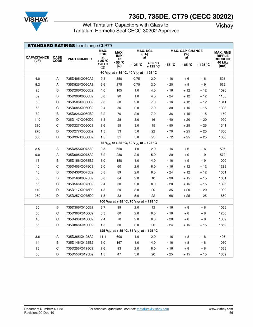
Document Number: 40053 For technical questions, contact: [email protected] www.vishay.comRevision: 20-Dec-10 56
735D, 735DE, CT79 (CECC 30202)Wet Tantalum Capacitors with Glass to
Tantalum Hermetic Seal CECC 30202 ApprovedVishay
STANDARD RATINGS to mil range CLR79
CAPACITANCE (µF)
CASE CODE PART NUMBER
MAX. ESR
at + 25 °C120 Hz
()
MAX. IMP.at
- 55 °C()
MAX. DCL (µA) at
MAX. CAP. CHANGE (%) at
MAX. RMS RIPPLE
CURRENT40 kHz (mA)+ 25 °C + 85 °C
+ 125 °C - 55 °C + 85 °C + 125 °C
60 VDC at + 85 °C, 40 VDC at + 125 °C
4.0 A 735D405X0060A2 9.3 550 0.75 2.0 - 16 + 6 + 6 525
8.2 A 735D825X0060A2 6.6 275 0.75 2.0 - 20 + 9 + 9 625
20 B 735D206X0060B2 4.0 105 1.0 4.0 - 16 + 12 + 12 1026
39 B 735D396X0060B2 3.0 90 1.0 4.0 - 24 + 12 + 12 1185
50 C 735D506X0060C2 2.6 50 2.0 7.0 - 16 + 12 + 12 1341
68 C 735D686X0060C2 2.4 50 2.0 7.0 - 30 + 15 + 15 1393
82 B 735D826X0060B2 3.2 70 2.0 7.0 - 36 + 15 + 15 1150
140 D 735D147X0060D2 1.3 28 3.0 16 - 40 + 20 + 20 1990
220 C 735D227X0060C2 2.6 55 3.0 15 - 50 + 25 + 25 1341
270 D 735D277X0060D2 1.5 33 5.0 22 - 70 + 25 + 25 1850
330 D 735D337X0060D2 1.5 31 5.0 25 - 72 + 25 + 25 1850
75 VDC at + 85 °C, 50 VDC at + 125 °C
3.5 A 735D355X0075A2 9.5 650 1.0 2.0 - 16 + 6 + 6 525
9.0 A 735D905X0075A2 8.2 280 2.0 5.0 - 20 + 9 + 9 572
15 B 735D156X0075B2 5.0 150 1.0 4.0 - 16 + 9 + 9 1000
40 C 735D406X0075C2 3.0 60 2.0 8.0 - 16 + 12 + 12 1293
43 B 735D436X0075B2 3.8 89 2.0 8.0 - 24 + 12 + 12 1051
56 B 735D566X0075B2 3.8 84 2.0 10 - 30 + 15 + 15 1051
56 C 735D566X0075C2 2.4 60 2.0 8.0 - 28 + 15 + 15 1396
110 D 735D117X0075D2 1.3 29 3.0 20 - 35 + 20 + 20 1990
250 D 735D257X0075D2 1.5 33 5.0 22 - 68 + 25 + 25 1850
100 VDC at + 85 °C, 70 VDC at + 125 °C
30 B 735D306X0100B2 3.7 99 2.0 12 - 16 + 8 + 8 1065
30 C 735D306X0100C2 3.3 80 2.0 8.0 - 16 + 8 + 8 1200
43 C 735D436X0100C2 2.4 70 2.0 8.0 - 20 + 8 + 8 1389
86 D 735D866X0100D2 1.5 30 3.0 20 - 24 + 15 + 15 1859
125 VDC at + 85 °C, 85 VDC at + 125 °C
3.6 A 735D365X0125A2 11.1 600 1.0 2.0 - 16 + 8 + 8 495
14 B 735D146X0125B2 5.0 167 1.0 4.0 - 16 + 8 + 8 1050
25 C 735D256X0125C2 2.6 93 2.0 8.0 - 16 + 8 + 8 1335
56 D 735D556X0125D2 1.5 47 3.0 20 - 25 + 15 + 15 1859
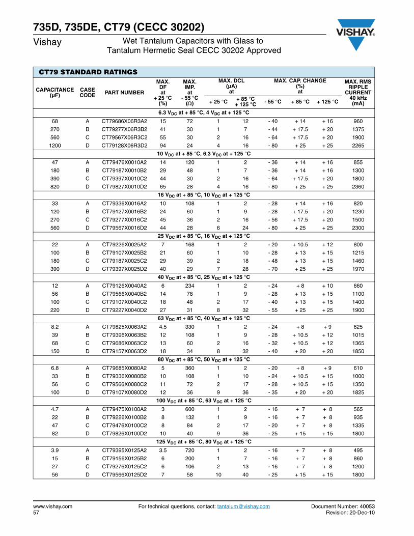
www.vishay.com For technical questions, contact: [email protected] Document Number: 4005357 Revision: 20-Dec-10
735D, 735DE, CT79 (CECC 30202)Vishay Wet Tantalum Capacitors with Glass to
Tantalum Hermetic Seal CECC 30202 Approved
CT79 STANDARD RATINGS
CAPACITANCE (µF)
CASE CODE PART NUMBER
MAX. DFat
+ 25 °C (%)
MAX. IMP.at
- 55 °C()
MAX. DCL (µA) at
MAX. CAP. CHANGE (%) at
MAX. RMS RIPPLE
CURRENT40 kHz (mA)+ 25 °C + 85 °C
+ 125 °C - 55 °C + 85 °C + 125 °C
6.3 VDC at + 85 °C, 4 VDC at + 125 °C
68 A CT79686X06R3A2 15 72 1 12 - 40 + 14 + 16 960
270 B CT79277X06R3B2 41 30 1 7 - 44 + 17.5 + 20 1375
560 C CT79567X06R3C2 55 30 2 16 - 64 + 17.5 + 20 1900
1200 D CT79128X06R3D2 94 24 4 16 - 80 + 25 + 25 2265
10 VDC at + 85 °C, 6.3 VDC at + 125 °C
47 A CT79476X0010A2 14 120 1 2 - 36 + 14 + 16 855
180 B CT79187X0010B2 29 48 1 7 - 36 + 14 + 16 1300
390 C CT79397X0010C2 44 30 2 16 - 64 + 17.5 + 20 1800
820 D CT79827X0010D2 65 28 4 16 - 80 + 25 + 25 2360
16 VDC at + 85 °C, 10 VDC at + 125 °C
33 A CT79336X0016A2 10 108 1 2 - 28 + 14 + 16 820
120 B CT79127X0016B2 24 60 1 9 - 28 + 17.5 + 20 1230
270 C CT79277X0016C2 45 36 2 16 - 56 + 17.5 + 20 1500
560 D CT79567X0016D2 44 28 6 24 - 80 + 25 + 25 2300
25 VDC at + 85 °C, 16 VDC at + 125 °C
22 A CT79226X0025A2 7 168 1 2 - 20 + 10.5 + 12 800
100 B CT79107X0025B2 21 60 1 10 - 28 + 13 + 15 1215
180 C CT79187X0025C2 29 39 2 18 - 48 + 13 + 15 1460
390 D CT79397X0025D2 40 29 7 28 - 70 + 25 + 25 1970
40 VDC at + 85 °C, 25 VDC at + 125 °C
12 A CT79126X0040A2 6 234 1 2 - 24 + 8 + 10 660
56 B CT79566X0040B2 14 78 1 9 - 28 + 13 + 15 1100
100 C CT79107X0040C2 18 48 2 17 - 40 + 13 + 15 1400
220 D CT79227X0040D2 27 31 8 32 - 55 + 25 + 25 1900
63 VDC at + 85 °C, 40 VDC at + 125 °C
8.2 A CT79825X0063A2 4.5 330 1 2 - 24 + 8 + 9 625
39 B CT79396X0063B2 12 108 1 9 - 28 + 10.5 + 12 1015
68 C CT79686X0063C2 13 60 2 16 - 32 + 10.5 + 12 1365
150 D CT79157X0063D2 18 34 8 32 - 40 + 20 + 20 1850
80 VDC at + 85 °C, 50 VDC at + 125 °C
6.8 A CT79685X0080A2 5 360 1 2 - 20 + 8 + 9 610
33 B CT79336X0080B2 10 108 1 10 - 24 + 10.5 + 15 1000
56 C CT79566X0080C2 11 72 2 17 - 28 + 10.5 + 15 1350
100 D CT79107X0080D2 12 36 9 36 - 35 + 20 + 20 1825
100 VDC at + 85 °C, 63 VDC at + 125 °C
4.7 A CT79475X0100A2 3 600 1 2 - 16 + 7 + 8 565
22 B CT79226X0100B2 8 132 1 9 - 16 + 7 + 8 935
47 C CT79476X0100C2 8 84 2 17 - 20 + 7 + 8 1335
82 D CT79826X0100D2 10 40 9 36 - 25 + 15 + 15 1800
125 VDC at + 85 °C, 80 VDC at + 125 °C
3.9 A CT79395X0125A2 3.5 720 1 2 - 16 + 7 + 8 495
15 B CT79156X0125B2 6 200 1 7 - 16 + 7 + 8 860
27 C CT79276X0125C2 6 106 2 13 - 16 + 7 + 8 1200
56 D CT79566X0125D2 7 58 10 40 - 25 + 15 + 15 1800
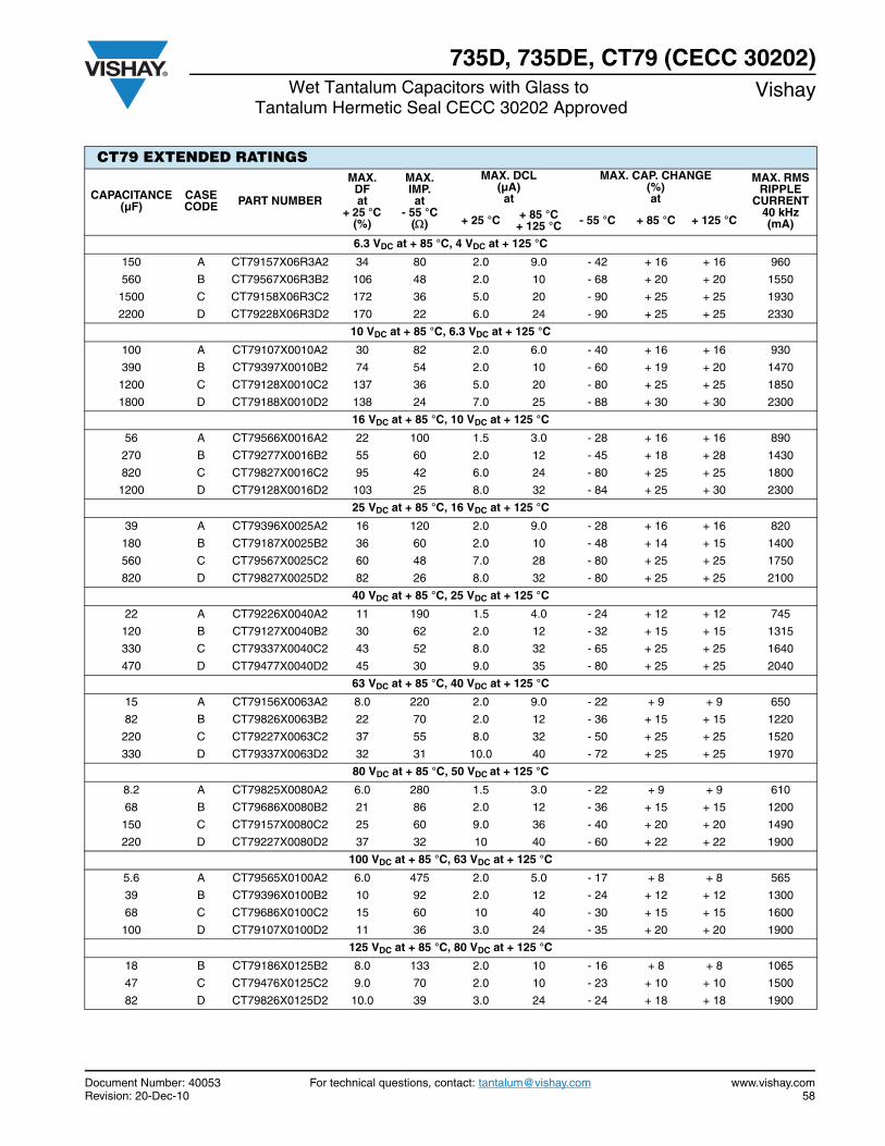
Document Number: 40053 For technical questions, contact: [email protected] www.vishay.comRevision: 20-Dec-10 58
735D, 735DE, CT79 (CECC 30202)Wet Tantalum Capacitors with Glass to
Tantalum Hermetic Seal CECC 30202 ApprovedVishay
CT79 EXTENDED RATINGS
CAPACITANCE (µF)
CASE CODE PART NUMBER
MAX. DFat
+ 25 °C (%)
MAX. IMP.at
- 55 °C()
MAX. DCL (µA) at
MAX. CAP. CHANGE (%) at
MAX. RMS RIPPLE
CURRENT40 kHz (mA)+ 25 °C + 85 °C
+ 125 °C - 55 °C + 85 °C + 125 °C
6.3 VDC at + 85 °C, 4 VDC at + 125 °C
150 A CT79157X06R3A2 34 80 2.0 9.0 - 42 + 16 + 16 960
560 B CT79567X06R3B2 106 48 2.0 10 - 68 + 20 + 20 1550
1500 C CT79158X06R3C2 172 36 5.0 20 - 90 + 25 + 25 1930
2200 D CT79228X06R3D2 170 22 6.0 24 - 90 + 25 + 25 2330
10 VDC at + 85 °C, 6.3 VDC at + 125 °C
100 A CT79107X0010A2 30 82 2.0 6.0 - 40 + 16 + 16 930
390 B CT79397X0010B2 74 54 2.0 10 - 60 + 19 + 20 1470
1200 C CT79128X0010C2 137 36 5.0 20 - 80 + 25 + 25 1850
1800 D CT79188X0010D2 138 24 7.0 25 - 88 + 30 + 30 2300
16 VDC at + 85 °C, 10 VDC at + 125 °C
56 A CT79566X0016A2 22 100 1.5 3.0 - 28 + 16 + 16 890
270 B CT79277X0016B2 55 60 2.0 12 - 45 + 18 + 28 1430
820 C CT79827X0016C2 95 42 6.0 24 - 80 + 25 + 25 1800
1200 D CT79128X0016D2 103 25 8.0 32 - 84 + 25 + 30 2300
25 VDC at + 85 °C, 16 VDC at + 125 °C
39 A CT79396X0025A2 16 120 2.0 9.0 - 28 + 16 + 16 820
180 B CT79187X0025B2 36 60 2.0 10 - 48 + 14 + 15 1400
560 C CT79567X0025C2 60 48 7.0 28 - 80 + 25 + 25 1750
820 D CT79827X0025D2 82 26 8.0 32 - 80 + 25 + 25 2100
40 VDC at + 85 °C, 25 VDC at + 125 °C
22 A CT79226X0040A2 11 190 1.5 4.0 - 24 + 12 + 12 745
120 B CT79127X0040B2 30 62 2.0 12 - 32 + 15 + 15 1315
330 C CT79337X0040C2 43 52 8.0 32 - 65 + 25 + 25 1640
470 D CT79477X0040D2 45 30 9.0 35 - 80 + 25 + 25 2040
63 VDC at + 85 °C, 40 VDC at + 125 °C
15 A CT79156X0063A2 8.0 220 2.0 9.0 - 22 + 9 + 9 650
82 B CT79826X0063B2 22 70 2.0 12 - 36 + 15 + 15 1220
220 C CT79227X0063C2 37 55 8.0 32 - 50 + 25 + 25 1520
330 D CT79337X0063D2 32 31 10.0 40 - 72 + 25 + 25 1970
80 VDC at + 85 °C, 50 VDC at + 125 °C
8.2 A CT79825X0080A2 6.0 280 1.5 3.0 - 22 + 9 + 9 610
68 B CT79686X0080B2 21 86 2.0 12 - 36 + 15 + 15 1200
150 C CT79157X0080C2 25 60 9.0 36 - 40 + 20 + 20 1490
220 D CT79227X0080D2 37 32 10 40 - 60 + 22 + 22 1900
100 VDC at + 85 °C, 63 VDC at + 125 °C
5.6 A CT79565X0100A2 6.0 475 2.0 5.0 - 17 + 8 + 8 565
39 B CT79396X0100B2 10 92 2.0 12 - 24 + 12 + 12 1300
68 C CT79686X0100C2 15 60 10 40 - 30 + 15 + 15 1600
100 D CT79107X0100D2 11 36 3.0 24 - 35 + 20 + 20 1900
125 VDC at + 85 °C, 80 VDC at + 125 °C
18 B CT79186X0125B2 8.0 133 2.0 10 - 16 + 8 + 8 1065
47 C CT79476X0125C2 9.0 70 2.0 10 - 23 + 10 + 10 1500
82 D CT79826X0125D2 10.0 39 3.0 24 - 24 + 18 + 18 1900
Contents
M39006/30/31 ................. 60
136D ............................... 81
Tantalum Case
Low ESR
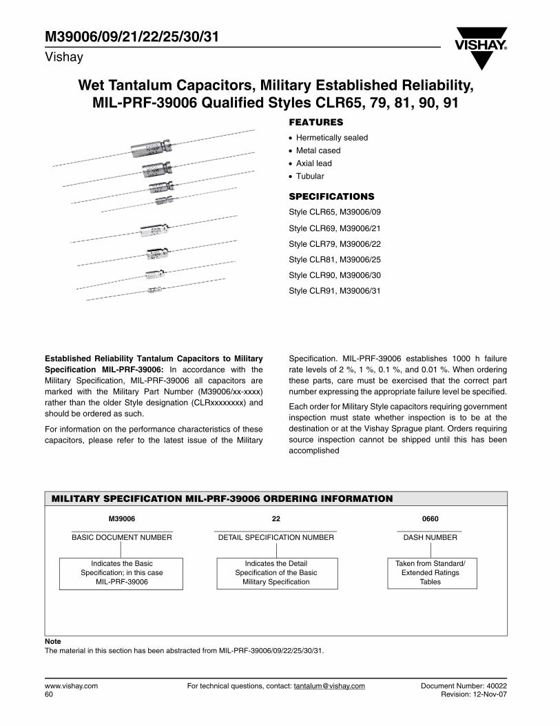
Wet Tantalum Capacitors, Military Established Reliability,MIL-PRF-39006 Qualified Styles CLR65, 79, 81, 90, 91
M39006/09/21/22/25/30/31Vishay
www.vishay.com For technical questions, contact: [email protected] Document Number: 4002260 Revision: 12-Nov-07
FEATURES
Hermetically sealed
Metal cased
Axial lead
Tubular
SPECIFICATIONS
Style CLR65, M39006/09
Style CLR69, M39006/21
Style CLR79, M39006/22
Style CLR81, M39006/25
Style CLR90, M39006/30
Style CLR91, M39006/31
Established Reliability Tantalum Capacitors to MilitarySpecification MIL-PRF-39006: In accordance with theMilitary Specification, MIL-PRF-39006 all capacitors aremarked with the Military Part Number (M39006/xx-xxxx)rather than the older Style designation (CLRxxxxxxxx) andshould be ordered as such.
For information on the performance characteristics of thesecapacitors, please refer to the latest issue of the Military
Specification. MIL-PRF-39006 establishes 1000 h failurerate levels of 2 %, 1 %, 0.1 %, and 0.01 %. When orderingthese parts, care must be exercised that the correct partnumber expressing the appropriate failure level be specified.
Each order for Military Style capacitors requiring governmentinspection must state whether inspection is to be at thedestination or at the Vishay Sprague plant. Orders requiringsource inspection cannot be shipped until this has beenaccomplished
MILITARY SPECIFICATION MIL-PRF-39006 ORDERING INFORMATION
M39006 22 0660
BASIC DOCUMENT NUMBER DETAIL SPECIFICATION NUMBER DASH NUMBER
Indicates the Basic Specification; in this case
MIL-PRF-39006
Indicates the Detail Specification of the Basic
Military Specification
Taken from Standard/Extended Ratings
Tables
NoteThe material in this section has been abstracted from MIL-PRF-39006/09/22/25/30/31.

Document Number: 40022 For technical questions, contact: [email protected] www.vishay.comRevision: 12-Nov-07 61
M39006/09/21/22/25/30/31Wet Tantalum Capacitors, Military Established Reliability,MIL-PRF-39006 Qualified Styles CLR65, 79, 81, 90, 91
Vishay
DIMENSIONS in inches [millimeters]
CASE CODE
BARE CASE WITH INSULATING
SLEEVE E LEAD LENGTH WEIGHT
(oz./g) (Max.)D L D (Max.) L (Max.)
T1 0.188 ± 0.016 [4.78 ± 0.41] 0.453 + 0.031 - 0.016 [11.51 + 0.79 - 0.41] 0.219 [5.56] 0.515 [13.08] 1.500 ± 0.250 [38.10 ± 6.35] 0.07 [2.0]
T2 0.281 ± 0.016 [7.14 ± 0.41] 0.641 + 0.031 - 0.016 [16.28 + 0.79 - 0.41] 0.312 [7.92] 0.704 [17.88] 2.250 ± 0.250 [57.15 ± 6.35] 0.18 [5.1]
T3 0.375 ± 0.016 [9.53 ± 0.41] 0.766 + 0.031 - 0.016 [19.46 + 0.79 - 0.41] 0.406 [10.31] 0.828 [21.03] 2.250 ± 0.250 [57.15 ± 6.35] 0.36 [10.2]
T4 0.375 ± 0.016 [9.53 ± 0.41] 1.062 + 0.031 - 0.016 [26.97 + 0.79 - 0.41] 0.406 [10.31] 1.126 [28.60] 2.250 ± 0.250 [57.15 ± 6.35] 0.49 [13.9]
CASE CODE
BARE CASE WITH INSULATING
SLEEVE E LEAD LENGTH WEIGHT
(oz./g) (Max.)D L D (Max.) L (Max.)
T1 0.188 ± 0.016 [4.78 ± 0.41] 0.453 + 0.031 - 0.016 [11.51 + 0.79 - 0.41] 0.219 [5.56] 0.515 [13.08] 1.500 ± 0.250 [38.10 ± 6.35] 0.09 [2.6]
T2 0.281 ± 0.016 [7.14 ± 0.41] 0.641 + 0.031 - 0.016 [16.28 + 0.79 - 0.41] 0.312 [7.92] 0.704 [17.88] 2.250 ± 0.250 [57.15 ± 6.35] 0.22 [6.2]
T3 0.375 ± 0.016 [9.53 ± 0.41] 0.766 + 0.031 - 0.016 [19.46 + 0.79 - 0.41] 0.406 [10.31] 0.828 [21.03] 2.250 ± 0.250 [57.15 ± 6.35] 0.41 [11.6]
T4 0.375 ± 0.016 [9.53 ± 0.41] 1.062 + 0.031 - 0.016 [26.97 + 0.79 - 0.41] 0.406 [10.31] 1.126 [28.60] 2.250 ± 0.250 [57.15 ± 6.35] 0.62 [17.7]
TERM. LOC. WITHIN0.031 [0.79] R.
OF TRUE POSITIONTERMINALWELDEDTO CASE
GLASS
D DIA.
INSULATING SLEEVE
0.250 [6.35] MAX.
EXTERNAL WELD
TANTALUM FEED -THROUGH 0.078[1.98] MAX. DIA.
0.094 [2.38]MAX.
CIRCUIT DIAGRAM0.025 ± 0.002[0.64 ± 0.05]
- +
E L E
STYLE CLR65STYLE CLR69
EXTERNAL WELD
D DIA.
0.094 [2.38]MAX.
TERMINALWELDEDTO CASE
INSULATING SLEEVE
TERM. LOC. WITHIN0.031 [0.79] R.
OF TRUE POSITION0.250 [6.35]
MAX.
TANTALUM FEED -THROUGH 0.078[1.98] MAX. DIA.
ELE
GLASS
CASE
CIRCUIT DIAGRAM0.025 ± 0.002[0.64 ± 0.05]
- +
STYLE CLR79STYLE CLR81STYLE CLR90STYLE CLR91
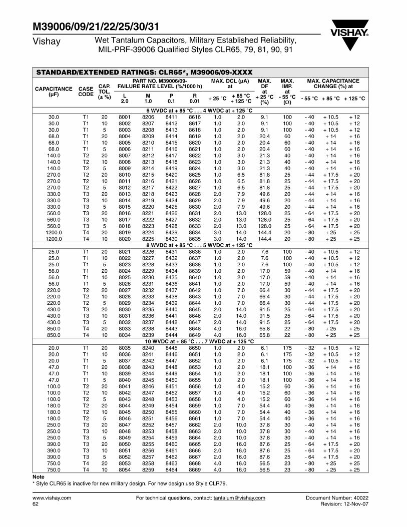
www.vishay.com For technical questions, contact: [email protected] Document Number: 4002262 Revision: 12-Nov-07
M39006/09/21/22/25/30/31Vishay Wet Tantalum Capacitors, Military Established Reliability,
MIL-PRF-39006 Qualified Styles CLR65, 79, 81, 90, 91
STANDARD/EXTENDED RATINGS: CLR65*, M39006/09-XXXX
CAPACITANCE (µF)
CASE CODE
CAP. TOL. (± %)
PART NO. M39006/09-FAILURE RATE LEVEL (%/1000 h)
MAX. DCL (µA)at
MAX. DFat
+ 25 °C(%)
MAX. IMP.at
- 55 °C()
MAX. CAPACITANCE CHANGE (%) at
L2.0
M1.0
P0.1
R0.01 + 25 °C + 85 °C
+ 125 °C - 55 °C + 85 °C + 125 °C
6 WVDC at + 85 °C . . . 4 WVDC at + 125 °C 30.0 T1 20 8001 8206 8411 8616 1.0 2.0 9.1 100 - 40 + 10.5 + 12 30.0 T1 10 8002 8207 8412 8617 1.0 2.0 9.1 100 - 40 + 10.5 + 12 30.0 T1 5 8003 8208 8413 8618 1.0 2.0 9.1 100 - 40 + 10.5 + 12 68.0 T1 20 8004 8209 8414 8619 1.0 2.0 20.4 60 - 40 + 14 + 16 68.0 T1 10 8005 8210 8415 8620 1.0 2.0 20.4 60 - 40 + 14 + 16 68.0 T1 5 8006 8211 8416 8621 1.0 2.0 20.4 60 - 40 + 14 + 16 140.0 T2 20 8007 8212 8417 8622 1.0 3.0 21.3 40 - 40 + 14 + 16 140.0 T2 10 8008 8213 8418 8623 1.0 3.0 21.3 40 - 40 + 14 + 16 140.0 T2 5 8009 8214 8419 8624 1.0 3.0 21.3 40 - 40 + 14 + 16 270.0 T2 20 8010 8215 8420 8625 1.0 6.5 81.8 25 - 44 + 17.5 + 20 270.0 T2 10 8011 8216 8421 8626 1.0 6.5 81.8 25 - 44 + 17.5 + 20 270.0 T2 5 8012 8217 8422 8627 1.0 6.5 81.8 25 - 44 + 17.5 + 20 330.0 T3 20 8013 8218 8423 8628 2.0 7.9 49.6 20 - 44 + 14 + 16 330.0 T3 10 8014 8219 8424 8629 2.0 7.9 49.6 20 - 44 + 14 + 16 330.0 T3 5 8015 8220 8425 8630 2.0 7.9 49.6 20 - 44 + 14 + 16 560.0 T3 20 8016 8221 8426 8631 2.0 13.0 128.0 25 - 64 + 17.5 + 20 560.0 T3 10 8017 8222 8427 8632 2.0 13.0 128.0 25 - 64 + 17.5 + 20 560.0 T3 5 8018 8223 8428 8633 2.0 13.0 128.0 25 - 64 + 17.5 + 20
1200.0 T4 20 8019 8224 8429 8634 3.0 14.0 144.4 20 - 80 + 25 + 25 1200.0 T4 10 8020 8225 8430 8635 3.0 14.0 144.4 20 - 80 + 25 + 25
8 WVDC at + 85 °C . . . 5 WVDC at + 125 °C 25.0 T1 20 8021 8226 8431 8636 1.0 2.0 7.6 100 - 40 + 10.5 + 12 25.0 T1 10 8022 8227 8432 8637 1.0 2.0 7.6 100 - 40 + 10.5 + 12 25.0 T1 5 8023 8228 8433 8638 1.0 2.0 7.6 100 - 40 + 10.5 + 12 56.0 T1 20 8024 8229 8434 8639 1.0 2.0 17.0 59 - 40 + 14 + 16 56.0 T1 10 8025 8230 8435 8640 1.0 2.0 17.0 59 - 40 + 14 + 16 56.0 T1 5 8026 8231 8436 8641 1.0 2.0 17.0 59 - 40 + 14 + 16 220.0 T2 20 8027 8232 8437 8642 1.0 7.0 66.4 30 - 44 + 17.5 + 20 220.0 T2 10 8028 8233 8438 8643 1.0 7.0 66.4 30 - 44 + 17.5 + 20 220.0 T2 5 8029 8234 8439 8644 1.0 7.0 66.4 30 - 44 + 17.5 + 20 430.0 T3 20 8030 8235 8440 8645 2.0 14.0 91.5 25 - 64 + 17.5 + 20 430.0 T3 10 8031 8236 8441 8646 2.0 14.0 91.5 25 - 64 + 17.5 + 20 430.0 T3 5 8032 8237 8442 8647 2.0 14.0 91.5 25 - 64 + 17.5 + 20 850.0 T4 20 8033 8238 8443 8648 4.0 16.0 65.8 22 - 80 + 25 + 25 850.0 T4 10 8034 8239 8444 8649 4.0 16.0 65.8 22 - 80 + 25 + 25
10 WVDC at + 85 °C . . . 7 WVDC at + 125 °C 20.0 T1 20 8035 8240 8445 8650 1.0 2.0 6.1 175 - 32 + 10.5 + 12 20.0 T1 10 8036 8241 8446 8651 1.0 2.0 6.1 175 - 32 + 10.5 + 12 20.0 T1 5 8037 8242 8447 8652 1.0 2.0 6.1 175 - 32 + 10.5 + 12 47.0 T1 20 8038 8243 8448 8653 1.0 2.0 18.1 100 - 36 + 14 + 16 47.0 T1 10 8039 8244 8449 8654 1.0 2.0 18.1 100 - 36 + 14 + 16 47.0 T1 5 8040 8245 8450 8655 1.0 2.0 18.1 100 - 36 + 14 + 16 100.0 T2 20 8041 8246 8451 8656 1.0 4.0 15.2 60 - 36 + 14 + 16 100.0 T2 10 8042 8247 8452 8657 1.0 4.0 15.2 60 - 36 + 14 + 16 100.0 T2 5 8043 8248 8453 8658 1.0 4.0 15.2 60 - 36 + 14 + 16 180.0 T2 20 8044 8249 8454 8659 1.0 7.0 54.4 40 - 36 + 14 + 16 180.0 T2 10 8045 8250 8455 8660 1.0 7.0 54.4 40 - 36 + 14 + 16 180.0 T2 5 8046 8251 8456 8661 1.0 7.0 54.4 40 - 36 + 14 + 16 250.0 T3 20 8047 8252 8457 8662 2.0 10.0 37.8 30 - 40 + 14 + 16 250.0 T3 10 8048 8253 8458 8663 2.0 10.0 37.8 30 - 40 + 14 + 16 250.0 T3 5 8049 8254 8459 8664 2.0 10.0 37.8 30 - 40 + 14 + 16 390.0 T3 20 8050 8255 8460 8665 2.0 16.0 87.6 25 - 64 + 17.5 + 20 390.0 T3 10 8051 8256 8461 8666 2.0 16.0 87.6 25 - 64 + 17.5 + 20 390.0 T3 5 8052 8257 8462 8667 2.0 16.0 87.6 25 - 64 + 17.5 + 20 750.0 T4 20 8053 8258 8463 8668 4.0 16.0 56.5 23 - 80 + 25 + 25 750.0 T4 10 8054 8259 8464 8669 4.0 16.0 56.5 23 - 80 + 25 + 25
Note* Style CLR65 is inactive for new military design. For new design use Style CLR79.
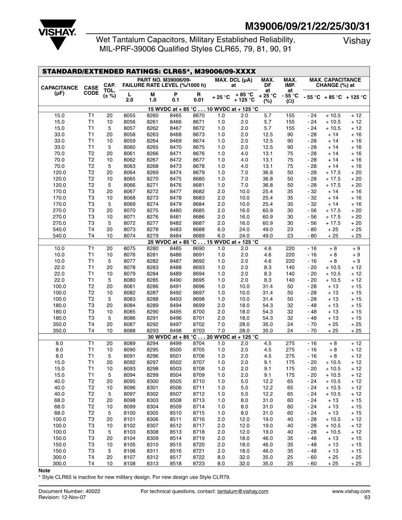
Document Number: 40022 For technical questions, contact: [email protected] www.vishay.comRevision: 12-Nov-07 63
M39006/09/21/22/25/30/31Wet Tantalum Capacitors, Military Established Reliability,MIL-PRF-39006 Qualified Styles CLR65, 79, 81, 90, 91
Vishay
STANDARD/EXTENDED RATINGS: CLR65*, M39006/09-XXXX
CAPACITANCE (µF)
CASE CODE
CAP. TOL. (± %)
PART NO. M39006/09-FAILURE RATE LEVEL (%/1000 h)
MAX. DCL (µA)at
MAX. DFat
+ 25 °C(%)
MAX. IMP.at
- 55 °C()
MAX. CAPACITANCE CHANGE (%) at
L2.0
M1.0
P0.1
R0.01 + 25 °C + 85 °C
+ 125 °C - 55 °C + 85 °C + 125 °C
15 WVDC at + 85 °C . . . 10 WVDC at + 125 °C 15.0 T1 20 8055 8260 8465 8670 1.0 2.0 5.7 155 - 24 + 10.5 + 12 15.0 T1 10 8056 8261 8466 8671 1.0 2.0 5.7 155 - 24 + 10.5 + 12 15.0 T1 5 8057 8262 8467 8672 1.0 2.0 5.7 155 - 24 + 10.5 + 12 33.0 T1 20 8058 8263 8468 8673 1.0 2.0 12.5 90 - 28 + 14 + 16 33.0 T1 10 8059 8264 8469 8674 1.0 2.0 12.5 90 - 28 + 14 + 16 33.0 T1 5 8060 8265 8470 8675 1.0 2.0 12.5 90 - 28 + 14 + 16 70.0 T2 20 8061 8266 8471 8676 1.0 4.0 13.1 75 - 28 + 14 + 16 70.0 T2 10 8062 8267 8472 8677 1.0 4.0 13.1 75 - 28 + 14 + 16 70.0 T2 5 8063 8268 8473 8678 1.0 4.0 13.1 75 - 28 + 14 + 16 120.0 T2 20 8064 8269 8474 8679 1.0 7.0 36.8 50 - 28 + 17.5 + 20 120.0 T2 10 8065 8270 8475 8680 1.0 7.0 36.8 50 - 28 + 17.5 + 20 120.0 T2 5 8066 8271 8476 8681 1.0 7.0 36.8 50 - 28 + 17.5 + 20 170.0 T3 20 8067 8272 8477 8682 2.0 10.0 25.4 35 - 32 + 14 + 16 170.0 T3 10 8068 8273 8478 8683 2.0 10.0 25.4 35 - 32 + 14 + 16 170.0 T3 5 8069 8274 8479 8684 2.0 10.0 25.4 35 - 32 + 14 + 16 270.0 T3 20 8070 8275 8480 8685 2.0 16.0 60.9 30 - 56 + 17.5 + 20 270.0 T3 10 8071 8276 8481 8686 2.0 16.0 60.9 30 - 56 + 17.5 + 20 270.0 T3 5 8072 8277 8482 8687 2.0 16.0 60.9 30 - 56 + 17.5 + 20 540.0 T4 20 8073 8278 8483 8688 6.0 24.0 49.0 23 - 80 + 25 + 25 540.0 T4 10 8074 8279 8484 8689 6.0 24.0 49.0 23 - 80 + 25 + 25
25 WVDC at + 85 °C . . . 15 WVDC at + 125 °C 10.0 T1 20 8075 8280 8485 8690 1.0 2.0 4.6 220 - 16 + 8 + 9 10.0 T1 10 8076 8281 8486 8691 1.0 2.0 4.6 220 - 16 + 8 + 9 10.0 T1 5 8077 8282 8487 8692 1.0 2.0 4.6 220 - 16 + 8 + 9 22.0 T1 20 8078 8283 8488 8693 1.0 2.0 8.3 140 - 20 + 10.5 + 12 22.0 T1 10 8079 8284 8489 8694 1.0 2.0 8.3 140 - 20 + 10.5 + 12 22.0 T1 5 8080 8285 8490 8695 1.0 2.0 8.3 140 - 20 + 10.5 + 12 100.0 T2 20 8081 8286 8491 8696 1.0 10.0 31.4 50 - 28 + 13 + 15 100.0 T2 10 8082 8287 8492 8697 1.0 10.0 31.4 50 - 28 + 13 + 15 100.0 T2 5 8083 8288 8493 8698 1.0 10.0 31.4 50 - 28 + 13 + 15 180.0 T3 20 8084 8289 8494 8699 2.0 18.0 54.3 32 - 48 + 13 + 15 180.0 T3 10 8085 8290 8495 8700 2.0 18.0 54.3 32 - 48 + 13 + 15 180.0 T3 5 8086 8291 8496 8701 2.0 18.0 54.3 32 - 48 + 13 + 15 350.0 T4 20 8087 8292 8497 8702 7.0 28.0 35.0 24 - 70 + 25 + 25 350.0 T4 10 8088 8293 8498 8703 7.0 28.0 35.0 24 - 70 + 25 + 25
30 WVDC at + 85 °C . . . 20 WVDC at + 125 °C 8.0 T1 20 8089 8294 8499 8704 1.0 2.0 4.5 275 - 16 + 8 + 12 8.0 T1 10 8090 8295 8500 8705 1.0 2.0 4.5 275 - 16 + 8 + 12 8.0 T1 5 8091 8296 8501 8706 1.0 2.0 4.5 275 - 16 + 8 + 12 15.0 T1 20 8092 8297 8502 8707 1.0 2.0 9.1 175 - 20 + 10.5 + 12 15.0 T1 10 8093 8298 8503 8708 1.0 2.0 9.1 175 - 20 + 10.5 + 12 15.0 T1 5 8094 8299 8504 8709 1.0 2.0 9.1 175 - 20 + 10.5 + 12 40.0 T2 20 8095 8300 8505 8710 1.0 5.0 12.2 65 - 24 + 10.5 + 12 40.0 T2 10 8096 8301 8506 8711 1.0 5.0 12.2 65 - 24 + 10.5 + 12 40.0 T2 5 8097 8302 8507 8712 1.0 5.0 12.2 65 - 24 + 10.5 + 12 68.0 T2 20 8098 8303 8508 8713 1.0 8.0 31.0 60 - 24 + 13 + 15 68.0 T2 10 8099 8304 8509 8714 1.0 8.0 31.0 60 - 24 + 13 + 15 68.0 T2 5 8100 8305 8510 8715 1.0 8.0 31.0 60 - 24 + 13 + 15 100.0 T3 20 8101 8306 8511 8716 2.0 12.0 19.0 40 - 28 + 10.5 + 12 100.0 T3 10 8102 8307 8512 8717 2.0 12.0 19.0 40 - 28 + 10.5 + 12 100.0 T3 5 8103 8308 8513 8718 2.0 12.0 19.0 40 - 28 + 10.5 + 12 150.0 T3 20 8104 8309 8514 8719 2.0 18.0 46.0 35 - 48 + 13 + 15 150.0 T3 10 8105 8310 8515 8720 2.0 18.0 46.0 35 - 48 + 13 + 15 150.0 T3 5 8106 8311 8516 8721 2.0 18.0 46.0 35 - 48 + 13 + 15 300.0 T4 20 8107 8312 8517 8722 8.0 32.0 35.0 25 - 60 + 25 + 25 300.0 T4 10 8108 8313 8518 8723 8.0 32.0 35.0 25 - 60 + 25 + 25
Note * Style CLR65 is inactive for new military design. For new design use Style CLR79.
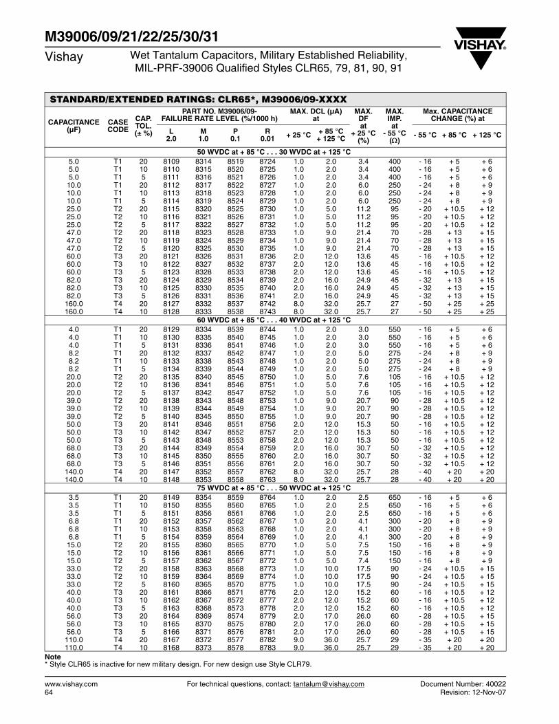
www.vishay.com For technical questions, contact: [email protected] Document Number: 4002264 Revision: 12-Nov-07
M39006/09/21/22/25/30/31Vishay Wet Tantalum Capacitors, Military Established Reliability,
MIL-PRF-39006 Qualified Styles CLR65, 79, 81, 90, 91
STANDARD/EXTENDED RATINGS: CLR65*, M39006/09-XXXX
CAPACITANCE (µF)
CASE CODE
CAP. TOL. (± %)
PART NO. M39006/09-FAILURE RATE LEVEL (%/1000 h)
MAX. DCL (µA)at
MAX. DFat
+ 25 °C(%)
MAX. IMP.at
- 55 °C()
Max. CAPACITANCE CHANGE (%) at
L2.0
M1.0
P0.1
R0.01 + 25 °C + 85 °C
+ 125 °C - 55 °C + 85 °C + 125 °C
50 WVDC at + 85 °C . . . 30 WVDC at + 125 °C 5.0 T1 20 8109 8314 8519 8724 1.0 2.0 3.4 400 - 16 + 5 + 6 5.0 T1 10 8110 8315 8520 8725 1.0 2.0 3.4 400 - 16 + 5 + 6 5.0 T1 5 8111 8316 8521 8726 1.0 2.0 3.4 400 - 16 + 5 + 6 10.0 T1 20 8112 8317 8522 8727 1.0 2.0 6.0 250 - 24 + 8 + 9 10.0 T1 10 8113 8318 8523 8728 1.0 2.0 6.0 250 - 24 + 8 + 9 10.0 T1 5 8114 8319 8524 8729 1.0 2.0 6.0 250 - 24 + 8 + 9 25.0 T2 20 8115 8320 8525 8730 1.0 5.0 11.2 95 - 20 + 10.5 + 12 25.0 T2 10 8116 8321 8526 8731 1.0 5.0 11.2 95 - 20 + 10.5 + 12 25.0 T2 5 8117 8322 8527 8732 1.0 5.0 11.2 95 - 20 + 10.5 + 12 47.0 T2 20 8118 8323 8528 8733 1.0 9.0 21.4 70 - 28 + 13 + 15 47.0 T2 10 8119 8324 8529 8734 1.0 9.0 21.4 70 - 28 + 13 + 15 47.0 T2 5 8120 8325 8530 8735 1.0 9.0 21.4 70 - 28 + 13 + 15 60.0 T3 20 8121 8326 8531 8736 2.0 12.0 13.6 45 - 16 + 10.5 + 12 60.0 T3 10 8122 8327 8532 8737 2.0 12.0 13.6 45 - 16 + 10.5 + 12 60.0 T3 5 8123 8328 8533 8738 2.0 12.0 13.6 45 - 16 + 10.5 + 12 82.0 T3 20 8124 8329 8534 8739 2.0 16.0 24.9 45 - 32 + 13 + 15 82.0 T3 10 8125 8330 8535 8740 2.0 16.0 24.9 45 - 32 + 13 + 15 82.0 T3 5 8126 8331 8536 8741 2.0 16.0 24.9 45 - 32 + 13 + 15 160.0 T4 20 8127 8332 8537 8742 8.0 32.0 25.7 27 - 50 + 25 + 25 160.0 T4 10 8128 8333 8538 8743 8.0 32.0 25.7 27 - 50 + 25 + 25
60 WVDC at + 85 °C . . . 40 WVDC at + 125 °C 4.0 T1 20 8129 8334 8539 8744 1.0 2.0 3.0 550 - 16 + 5 + 6 4.0 T1 10 8130 8335 8540 8745 1.0 2.0 3.0 550 - 16 + 5 + 6 4.0 T1 5 8131 8336 8541 8746 1.0 2.0 3.0 550 - 16 + 5 + 6 8.2 T1 20 8132 8337 8542 8747 1.0 2.0 5.0 275 - 24 + 8 + 9 8.2 T1 10 8133 8338 8543 8748 1.0 2.0 5.0 275 - 24 + 8 + 9 8.2 T1 5 8134 8339 8544 8749 1.0 2.0 5.0 275 - 24 + 8 + 9 20.0 T2 20 8135 8340 8545 8750 1.0 5.0 7.6 105 - 16 + 10.5 + 12 20.0 T2 10 8136 8341 8546 8751 1.0 5.0 7.6 105 - 16 + 10.5 + 12 20.0 T2 5 8137 8342 8547 8752 1.0 5.0 7.6 105 - 16 + 10.5 + 12 39.0 T2 20 8138 8343 8548 8753 1.0 9.0 20.7 90 - 28 + 10.5 + 12 39.0 T2 10 8139 8344 8549 8754 1.0 9.0 20.7 90 - 28 + 10.5 + 12 39.0 T2 5 8140 8345 8550 8755 1.0 9.0 20.7 90 - 28 + 10.5 + 12 50.0 T3 20 8141 8346 8551 8756 2.0 12.0 15.3 50 - 16 + 10.5 + 12 50.0 T3 10 8142 8347 8552 8757 2.0 12.0 15.3 50 - 16 + 10.5 + 12 50.0 T3 5 8143 8348 8553 8758 2.0 12.0 15.3 50 - 16 + 10.5 + 12 68.0 T3 20 8144 8349 8554 8759 2.0 16.0 30.7 50 - 32 + 10.5 + 12 68.0 T3 10 8145 8350 8555 8760 2.0 16.0 30.7 50 - 32 + 10.5 + 12 68.0 T3 5 8146 8351 8556 8761 2.0 16.0 30.7 50 - 32 + 10.5 + 12 140.0 T4 20 8147 8352 8557 8762 8.0 32.0 25.7 28 - 40 + 20 + 20 140.0 T4 10 8148 8353 8558 8763 8.0 32.0 25.7 28 - 40 + 20 + 20
75 WVDC at + 85 °C . . . 50 WVDC at + 125 °C 3.5 T1 20 8149 8354 8559 8764 1.0 2.0 2.5 650 - 16 + 5 + 6 3.5 T1 10 8150 8355 8560 8765 1.0 2.0 2.5 650 - 16 + 5 + 6 3.5 T1 5 8151 8356 8561 8766 1.0 2.0 2.5 650 - 16 + 5 + 6 6.8 T1 20 8152 8357 8562 8767 1.0 2.0 4.1 300 - 20 + 8 + 9 6.8 T1 10 8153 8358 8563 8768 1.0 2.0 4.1 300 - 20 + 8 + 9 6.8 T1 5 8154 8359 8564 8769 1.0 2.0 4.1 300 - 20 + 8 + 9 15.0 T2 20 8155 8360 8565 8770 1.0 5.0 7.5 150 - 16 + 8 + 9 15.0 T2 10 8156 8361 8566 8771 1.0 5.0 7.5 150 - 16 + 8 + 9 15.0 T2 5 8157 8362 8567 8772 1.0 5.0 7.4 150 - 16 + 8 + 9 33.0 T2 20 8158 8363 8568 8773 1.0 10.0 17.5 90 - 24 + 10.5 + 15 33.0 T2 10 8159 8364 8569 8774 1.0 10.0 17.5 90 - 24 + 10.5 + 15 33.0 T2 5 8160 8365 8570 8775 1.0 10.0 17.5 90 - 24 + 10.5 + 15 40.0 T3 20 8161 8366 8571 8776 2.0 12.0 15.2 60 - 16 + 10.5 + 12 40.0 T3 10 8162 8367 8572 8777 2.0 12.0 15.2 60 - 16 + 10.5 + 12 40.0 T3 5 8163 8368 8573 8778 2.0 12.0 15.2 60 - 16 + 10.5 + 12 56.0 T3 20 8164 8369 8574 8779 2.0 17.0 26.0 60 - 28 + 10.5 + 15 56.0 T3 10 8165 8370 8575 8780 2.0 17.0 26.0 60 - 28 + 10.5 + 15 56.0 T3 5 8166 8371 8576 8781 2.0 17.0 26.0 60 - 28 + 10.5 + 15 110.0 T4 20 8167 8372 8577 8782 9.0 36.0 25.7 29 - 35 + 20 + 20 110.0 T4 10 8168 8373 8578 8783 9.0 36.0 25.7 29 - 35 + 20 + 20
Note * Style CLR65 is inactive for new military design. For new design use Style CLR79.
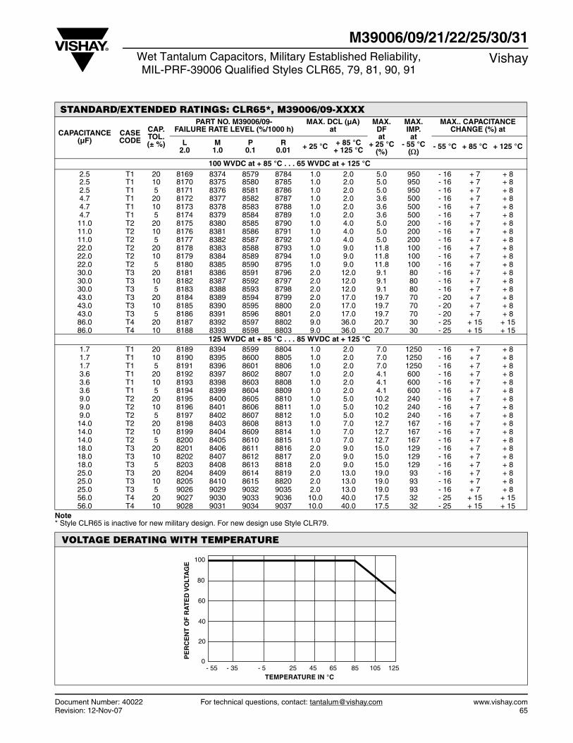
Document Number: 40022 For technical questions, contact: [email protected] www.vishay.comRevision: 12-Nov-07 65
M39006/09/21/22/25/30/31Wet Tantalum Capacitors, Military Established Reliability,MIL-PRF-39006 Qualified Styles CLR65, 79, 81, 90, 91
Vishay
STANDARD/EXTENDED RATINGS: CLR65*, M39006/09-XXXX
CAPACITANCE (µF)
CASE CODE
CAP. TOL. (± %)
PART NO. M39006/09-FAILURE RATE LEVEL (%/1000 h)
MAX. DCL (µA)at
MAX. DFat
+ 25 °C(%)
MAX. IMP.at
- 55 °C()
MAX.. CAPACITANCE CHANGE (%) at
L2.0
M1.0
P0.1
R0.01 + 25 °C + 85 °C
+ 125 °C - 55 °C + 85 °C + 125 °C
100 WVDC at + 85 °C . . . 65 WVDC at + 125 °C 2.5 T1 20 8169 8374 8579 8784 1.0 2.0 5.0 950 - 16 + 7 + 8 2.5 T1 10 8170 8375 8580 8785 1.0 2.0 5.0 950 - 16 + 7 + 8 2.5 T1 5 8171 8376 8581 8786 1.0 2.0 5.0 950 - 16 + 7 + 8 4.7 T1 20 8172 8377 8582 8787 1.0 2.0 3.6 500 - 16 + 7 + 8 4.7 T1 10 8173 8378 8583 8788 1.0 2.0 3.6 500 - 16 + 7 + 8 4.7 T1 5 8174 8379 8584 8789 1.0 2.0 3.6 500 - 16 + 7 + 8 11.0 T2 20 8175 8380 8585 8790 1.0 4.0 5.0 200 - 16 + 7 + 8 11.0 T2 10 8176 8381 8586 8791 1.0 4.0 5.0 200 - 16 + 7 + 8 11.0 T2 5 8177 8382 8587 8792 1.0 4.0 5.0 200 - 16 + 7 + 8 22.0 T2 20 8178 8383 8588 8793 1.0 9.0 11.8 100 - 16 + 7 + 8 22.0 T2 10 8179 8384 8589 8794 1.0 9.0 11.8 100 - 16 + 7 + 8 22.0 T2 5 8180 8385 8590 8795 1.0 9.0 11.8 100 - 16 + 7 + 8 30.0 T3 20 8181 8386 8591 8796 2.0 12.0 9.1 80 - 16 + 7 + 8 30.0 T3 10 8182 8387 8592 8797 2.0 12.0 9.1 80 - 16 + 7 + 8 30.0 T3 5 8183 8388 8593 8798 2.0 12.0 9.1 80 - 16 + 7 + 8 43.0 T3 20 8184 8389 8594 8799 2.0 17.0 19.7 70 - 20 + 7 + 8 43.0 T3 10 8185 8390 8595 8800 2.0 17.0 19.7 70 - 20 + 7 + 8 43.0 T3 5 8186 8391 8596 8801 2.0 17.0 19.7 70 - 20 + 7 + 8 86.0 T4 20 8187 8392 8597 8802 9.0 36.0 20.7 30 - 25 + 15 + 15 86.0 T4 10 8188 8393 8598 8803 9.0 36.0 20.7 30 - 25 + 15 + 15
125 WVDC at + 85 °C . . . 85 WVDC at + 125 °C 1.7 T1 20 8189 8394 8599 8804 1.0 2.0 7.0 1250 - 16 + 7 + 8 1.7 T1 10 8190 8395 8600 8805 1.0 2.0 7.0 1250 - 16 + 7 + 8 1.7 T1 5 8191 8396 8601 8806 1.0 2.0 7.0 1250 - 16 + 7 + 8 3.6 T1 20 8192 8397 8602 8807 1.0 2.0 4.1 600 - 16 + 7 + 8 3.6 T1 10 8193 8398 8603 8808 1.0 2.0 4.1 600 - 16 + 7 + 8 3.6 T1 5 8194 8399 8604 8809 1.0 2.0 4.1 600 - 16 + 7 + 8 9.0 T2 20 8195 8400 8605 8810 1.0 5.0 10.2 240 - 16 + 7 + 8 9.0 T2 10 8196 8401 8606 8811 1.0 5.0 10.2 240 - 16 + 7 + 8 9.0 T2 5 8197 8402 8607 8812 1.0 5.0 10.2 240 - 16 + 7 + 8 14.0 T2 20 8198 8403 8608 8813 1.0 7.0 12.7 167 - 16 + 7 + 8 14.0 T2 10 8199 8404 8609 8814 1.0 7.0 12.7 167 - 16 + 7 + 8 14.0 T2 5 8200 8405 8610 8815 1.0 7.0 12.7 167 - 16 + 7 + 8 18.0 T3 20 8201 8406 8611 8816 2.0 9.0 15.0 129 - 16 + 7 + 8 18.0 T3 10 8202 8407 8612 8817 2.0 9.0 15.0 129 - 16 + 7 + 8 18.0 T3 5 8203 8408 8613 8818 2.0 9.0 15.0 129 - 16 + 7 + 8 25.0 T3 20 8204 8409 8614 8819 2.0 13.0 19.0 93 - 16 + 7 + 8 25.0 T3 10 8205 8410 8615 8820 2.0 13.0 19.0 93 - 16 + 7 + 8 25.0 T3 5 9026 9029 9032 9035 2.0 13.0 19.0 93 - 16 + 7 + 8 56.0 T4 20 9027 9030 9033 9036 10.0 40.0 17.5 32 - 25 + 15 + 15 56.0 T4 10 9028 9031 9034 9037 10.0 40.0 17.5 32 - 25 + 15 + 15
Note * Style CLR65 is inactive for new military design. For new design use Style CLR79.
VOLTAGE DERATING WITH TEMPERATURE
100
80
60
40
20
0- 55 - 35 - 5 25 45 65 85 105 125
PE
RC
EN
T O
F R
AT
ED
VO
LTA
GE
TEMPERATURE IN °C
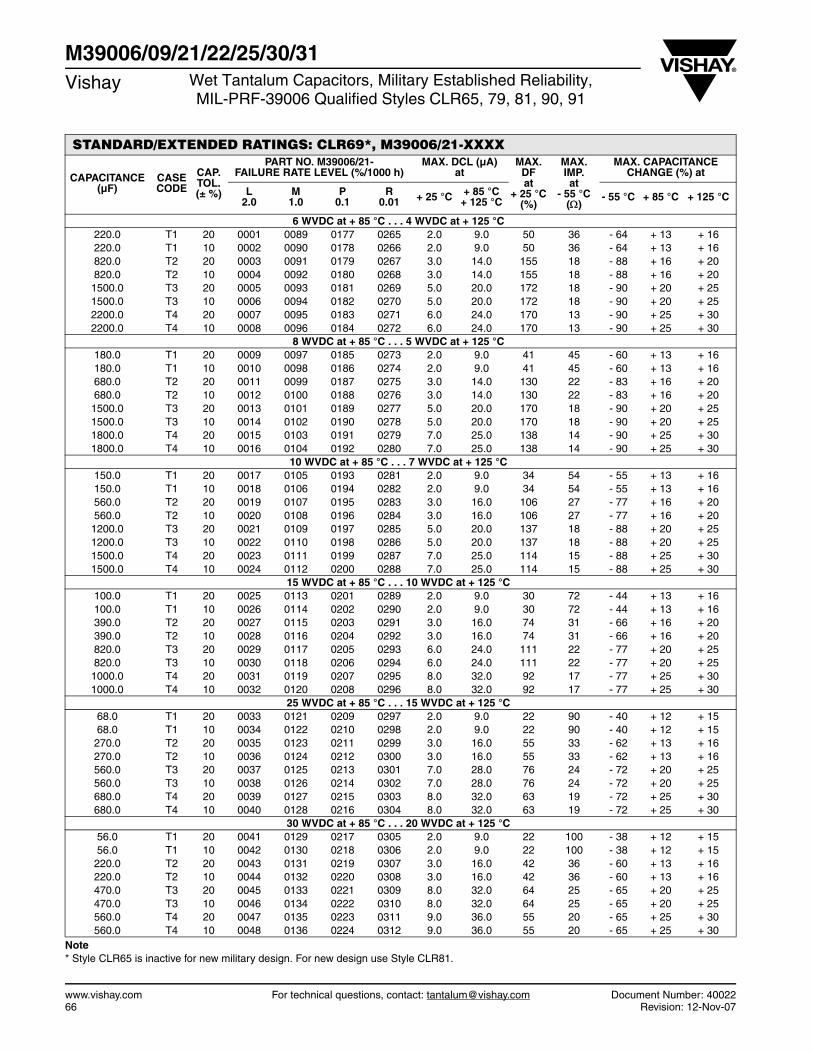
www.vishay.com For technical questions, contact: [email protected] Document Number: 4002266 Revision: 12-Nov-07
M39006/09/21/22/25/30/31Vishay Wet Tantalum Capacitors, Military Established Reliability,
MIL-PRF-39006 Qualified Styles CLR65, 79, 81, 90, 91
STANDARD/EXTENDED RATINGS: CLR69*, M39006/21-XXXX
CAPACITANCE (µF)
CASE CODE
CAP. TOL. (± %)
PART NO. M39006/21-FAILURE RATE LEVEL (%/1000 h)
MAX. DCL (µA)at
MAX. DFat
+ 25 °C(%)
MAX. IMP.at
- 55 °C()
MAX. CAPACITANCE CHANGE (%) at
L2.0
M1.0
P0.1
R0.01 + 25 °C + 85 °C
+ 125 °C - 55 °C + 85 °C + 125 °C
6 WVDC at + 85 °C . . . 4 WVDC at + 125 °C 220.0 T1 20 0001 0089 0177 0265 2.0 9.0 50 36 - 64 + 13 + 16 220.0 T1 10 0002 0090 0178 0266 2.0 9.0 50 36 - 64 + 13 + 16 820.0 T2 20 0003 0091 0179 0267 3.0 14.0 155 18 - 88 + 16 + 20 820.0 T2 10 0004 0092 0180 0268 3.0 14.0 155 18 - 88 + 16 + 20
1500.0 T3 20 0005 0093 0181 0269 5.0 20.0 172 18 - 90 + 20 + 25 1500.0 T3 10 0006 0094 0182 0270 5.0 20.0 172 18 - 90 + 20 + 25 2200.0 T4 20 0007 0095 0183 0271 6.0 24.0 170 13 - 90 + 25 + 30 2200.0 T4 10 0008 0096 0184 0272 6.0 24.0 170 13 - 90 + 25 + 30
8 WVDC at + 85 °C . . . 5 WVDC at + 125 °C 180.0 T1 20 0009 0097 0185 0273 2.0 9.0 41 45 - 60 + 13 + 16 180.0 T1 10 0010 0098 0186 0274 2.0 9.0 41 45 - 60 + 13 + 16 680.0 T2 20 0011 0099 0187 0275 3.0 14.0 130 22 - 83 + 16 + 20 680.0 T2 10 0012 0100 0188 0276 3.0 14.0 130 22 - 83 + 16 + 20
1500.0 T3 20 0013 0101 0189 0277 5.0 20.0 170 18 - 90 + 20 + 25 1500.0 T3 10 0014 0102 0190 0278 5.0 20.0 170 18 - 90 + 20 + 25 1800.0 T4 20 0015 0103 0191 0279 7.0 25.0 138 14 - 90 + 25 + 30 1800.0 T4 10 0016 0104 0192 0280 7.0 25.0 138 14 - 90 + 25 + 30
10 WVDC at + 85 °C . . . 7 WVDC at + 125 °C 150.0 T1 20 0017 0105 0193 0281 2.0 9.0 34 54 - 55 + 13 + 16 150.0 T1 10 0018 0106 0194 0282 2.0 9.0 34 54 - 55 + 13 + 16 560.0 T2 20 0019 0107 0195 0283 3.0 16.0 106 27 - 77 + 16 + 20 560.0 T2 10 0020 0108 0196 0284 3.0 16.0 106 27 - 77 + 16 + 20
1200.0 T3 20 0021 0109 0197 0285 5.0 20.0 137 18 - 88 + 20 + 25 1200.0 T3 10 0022 0110 0198 0286 5.0 20.0 137 18 - 88 + 20 + 25 1500.0 T4 20 0023 0111 0199 0287 7.0 25.0 114 15 - 88 + 25 + 30 1500.0 T4 10 0024 0112 0200 0288 7.0 25.0 114 15 - 88 + 25 + 30
15 WVDC at + 85 °C . . . 10 WVDC at + 125 °C 100.0 T1 20 0025 0113 0201 0289 2.0 9.0 30 72 - 44 + 13 + 16 100.0 T1 10 0026 0114 0202 0290 2.0 9.0 30 72 - 44 + 13 + 16 390.0 T2 20 0027 0115 0203 0291 3.0 16.0 74 31 - 66 + 16 + 20 390.0 T2 10 0028 0116 0204 0292 3.0 16.0 74 31 - 66 + 16 + 20 820.0 T3 20 0029 0117 0205 0293 6.0 24.0 111 22 - 77 + 20 + 25 820.0 T3 10 0030 0118 0206 0294 6.0 24.0 111 22 - 77 + 20 + 25
1000.0 T4 20 0031 0119 0207 0295 8.0 32.0 92 17 - 77 + 25 + 30 1000.0 T4 10 0032 0120 0208 0296 8.0 32.0 92 17 - 77 + 25 + 30
25 WVDC at + 85 °C . . . 15 WVDC at + 125 °C 68.0 T1 20 0033 0121 0209 0297 2.0 9.0 22 90 - 40 + 12 + 15 68.0 T1 10 0034 0122 0210 0298 2.0 9.0 22 90 - 40 + 12 + 15 270.0 T2 20 0035 0123 0211 0299 3.0 16.0 55 33 - 62 + 13 + 16 270.0 T2 10 0036 0124 0212 0300 3.0 16.0 55 33 - 62 + 13 + 16 560.0 T3 20 0037 0125 0213 0301 7.0 28.0 76 24 - 72 + 20 + 25 560.0 T3 10 0038 0126 0214 0302 7.0 28.0 76 24 - 72 + 20 + 25 680.0 T4 20 0039 0127 0215 0303 8.0 32.0 63 19 - 72 + 25 + 30 680.0 T4 10 0040 0128 0216 0304 8.0 32.0 63 19 - 72 + 25 + 30
30 WVDC at + 85 °C . . . 20 WVDC at + 125 °C 56.0 T1 20 0041 0129 0217 0305 2.0 9.0 22 100 - 38 + 12 + 15 56.0 T1 10 0042 0130 0218 0306 2.0 9.0 22 100 - 38 + 12 + 15 220.0 T2 20 0043 0131 0219 0307 3.0 16.0 42 36 - 60 + 13 + 16 220.0 T2 10 0044 0132 0220 0308 3.0 16.0 42 36 - 60 + 13 + 16 470.0 T3 20 0045 0133 0221 0309 8.0 32.0 64 25 - 65 + 20 + 25 470.0 T3 10 0046 0134 0222 0310 8.0 32.0 64 25 - 65 + 20 + 25 560.0 T4 20 0047 0135 0223 0311 9.0 36.0 55 20 - 65 + 25 + 30 560.0 T4 10 0048 0136 0224 0312 9.0 36.0 55 20 - 65 + 25 + 30
Note* Style CLR65 is inactive for new military design. For new design use Style CLR81.
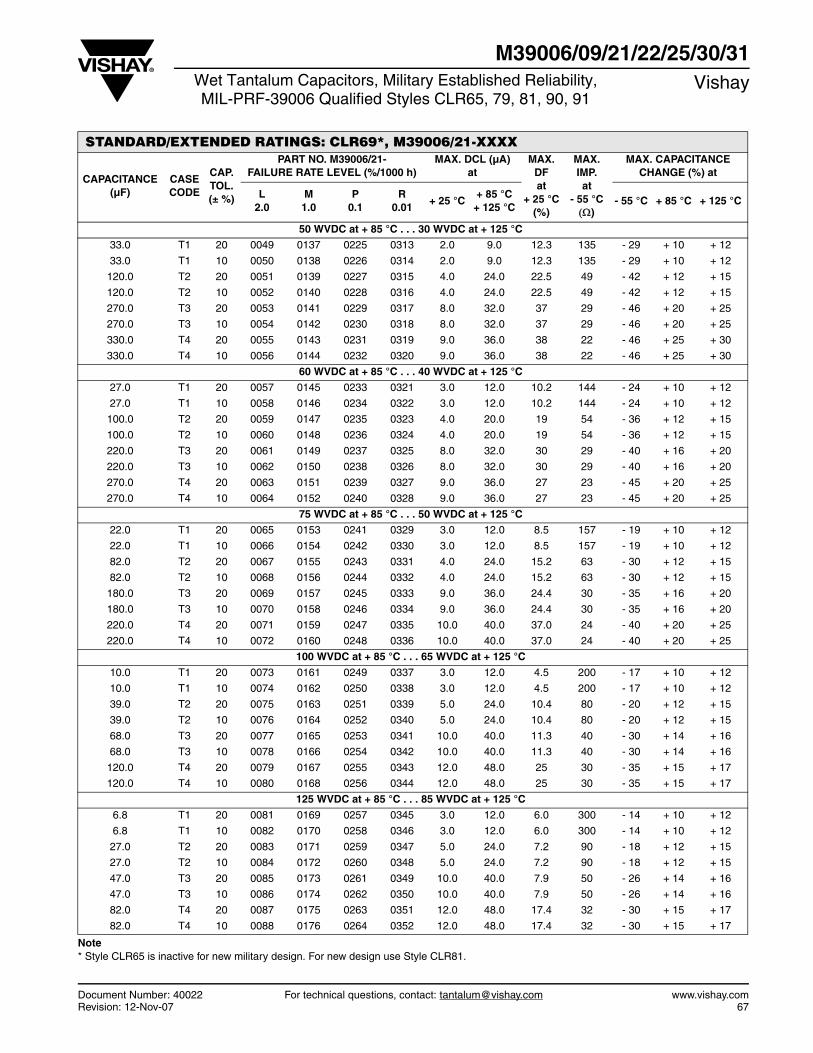
Document Number: 40022 For technical questions, contact: [email protected] www.vishay.comRevision: 12-Nov-07 67
M39006/09/21/22/25/30/31Wet Tantalum Capacitors, Military Established Reliability,MIL-PRF-39006 Qualified Styles CLR65, 79, 81, 90, 91
Vishay
STANDARD/EXTENDED RATINGS: CLR69*, M39006/21-XXXX
CAPACITANCE (µF)
CASE CODE
CAP. TOL. (± %)
PART NO. M39006/21-FAILURE RATE LEVEL (%/1000 h)
MAX. DCL (µA)at
MAX. DFat
+ 25 °C(%)
MAX. IMP.at
- 55 °C)
MAX. CAPACITANCE CHANGE (%) at
L2.0
M1.0
P0.1
R0.01
+ 25 °C+ 85 °C
+ 125 °C- 55 °C + 85 °C + 125 °C
50 WVDC at + 85 °C . . . 30 WVDC at + 125 °C
33.0 T1 20 0049 0137 0225 0313 2.0 9.0 12.3 135 - 29 + 10 + 12
33.0 T1 10 0050 0138 0226 0314 2.0 9.0 12.3 135 - 29 + 10 + 12
120.0 T2 20 0051 0139 0227 0315 4.0 24.0 22.5 49 - 42 + 12 + 15
120.0 T2 10 0052 0140 0228 0316 4.0 24.0 22.5 49 - 42 + 12 + 15
270.0 T3 20 0053 0141 0229 0317 8.0 32.0 37 29 - 46 + 20 + 25
270.0 T3 10 0054 0142 0230 0318 8.0 32.0 37 29 - 46 + 20 + 25
330.0 T4 20 0055 0143 0231 0319 9.0 36.0 38 22 - 46 + 25 + 30
330.0 T4 10 0056 0144 0232 0320 9.0 36.0 38 22 - 46 + 25 + 30
60 WVDC at + 85 °C . . . 40 WVDC at + 125 °C
27.0 T1 20 0057 0145 0233 0321 3.0 12.0 10.2 144 - 24 + 10 + 12
27.0 T1 10 0058 0146 0234 0322 3.0 12.0 10.2 144 - 24 + 10 + 12
100.0 T2 20 0059 0147 0235 0323 4.0 20.0 19 54 - 36 + 12 + 15
100.0 T2 10 0060 0148 0236 0324 4.0 20.0 19 54 - 36 + 12 + 15
220.0 T3 20 0061 0149 0237 0325 8.0 32.0 30 29 - 40 + 16 + 20
220.0 T3 10 0062 0150 0238 0326 8.0 32.0 30 29 - 40 + 16 + 20
270.0 T4 20 0063 0151 0239 0327 9.0 36.0 27 23 - 45 + 20 + 25
270.0 T4 10 0064 0152 0240 0328 9.0 36.0 27 23 - 45 + 20 + 25
75 WVDC at + 85 °C . . . 50 WVDC at + 125 °C
22.0 T1 20 0065 0153 0241 0329 3.0 12.0 8.5 157 - 19 + 10 + 12
22.0 T1 10 0066 0154 0242 0330 3.0 12.0 8.5 157 - 19 + 10 + 12
82.0 T2 20 0067 0155 0243 0331 4.0 24.0 15.2 63 - 30 + 12 + 15
82.0 T2 10 0068 0156 0244 0332 4.0 24.0 15.2 63 - 30 + 12 + 15
180.0 T3 20 0069 0157 0245 0333 9.0 36.0 24.4 30 - 35 + 16 + 20
180.0 T3 10 0070 0158 0246 0334 9.0 36.0 24.4 30 - 35 + 16 + 20
220.0 T4 20 0071 0159 0247 0335 10.0 40.0 37.0 24 - 40 + 20 + 25
220.0 T4 10 0072 0160 0248 0336 10.0 40.0 37.0 24 - 40 + 20 + 25
100 WVDC at + 85 °C . . . 65 WVDC at + 125 °C
10.0 T1 20 0073 0161 0249 0337 3.0 12.0 4.5 200 - 17 + 10 + 12
10.0 T1 10 0074 0162 0250 0338 3.0 12.0 4.5 200 - 17 + 10 + 12
39.0 T2 20 0075 0163 0251 0339 5.0 24.0 10.4 80 - 20 + 12 + 15
39.0 T2 10 0076 0164 0252 0340 5.0 24.0 10.4 80 - 20 + 12 + 15
68.0 T3 20 0077 0165 0253 0341 10.0 40.0 11.3 40 - 30 + 14 + 16
68.0 T3 10 0078 0166 0254 0342 10.0 40.0 11.3 40 - 30 + 14 + 16
120.0 T4 20 0079 0167 0255 0343 12.0 48.0 25 30 - 35 + 15 + 17
120.0 T4 10 0080 0168 0256 0344 12.0 48.0 25 30 - 35 + 15 + 17
125 WVDC at + 85 °C . . . 85 WVDC at + 125 °C
6.8 T1 20 0081 0169 0257 0345 3.0 12.0 6.0 300 - 14 + 10 + 12
6.8 T1 10 0082 0170 0258 0346 3.0 12.0 6.0 300 - 14 + 10 + 12
27.0 T2 20 0083 0171 0259 0347 5.0 24.0 7.2 90 - 18 + 12 + 15
27.0 T2 10 0084 0172 0260 0348 5.0 24.0 7.2 90 - 18 + 12 + 15
47.0 T3 20 0085 0173 0261 0349 10.0 40.0 7.9 50 - 26 + 14 + 16
47.0 T3 10 0086 0174 0262 0350 10.0 40.0 7.9 50 - 26 + 14 + 16
82.0 T4 20 0087 0175 0263 0351 12.0 48.0 17.4 32 - 30 + 15 + 17
82.0 T4 10 0088 0176 0264 0352 12.0 48.0 17.4 32 - 30 + 15 + 17
Note* Style CLR65 is inactive for new military design. For new design use Style CLR81.
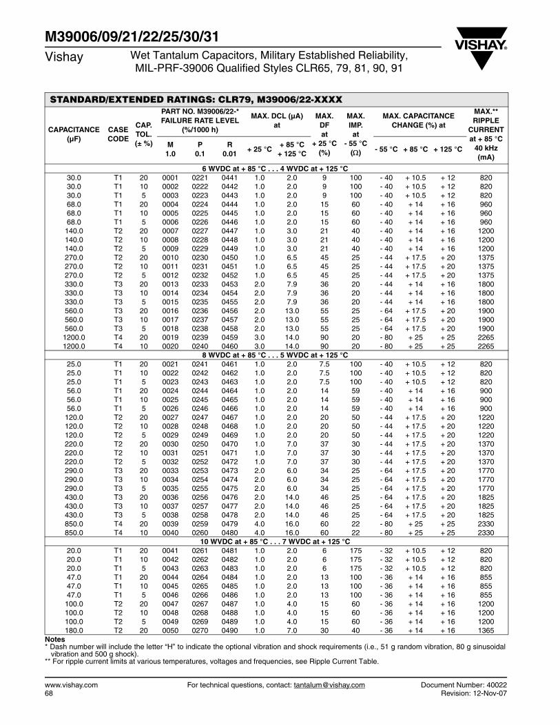
www.vishay.com For technical questions, contact: [email protected] Document Number: 4002268 Revision: 12-Nov-07
M39006/09/21/22/25/30/31Vishay Wet Tantalum Capacitors, Military Established Reliability,
MIL-PRF-39006 Qualified Styles CLR65, 79, 81, 90, 91
STANDARD/EXTENDED RATINGS: CLR79, M39006/22-XXXX
CAPACITANCE (µF)
CASE CODE
CAP. TOL. (± %)
PART NO. M39006/22-*FAILURE RATE LEVEL
(%/1000 h)
MAX. DCL (µA)at
MAX. DFat
+ 25 °C(%)
MAX. IMP.at
- 55 °C()
MAX. CAPACITANCE CHANGE (%) at
MAX.**RIPPLE
CURRENT at + 85 °C
40 kHz (mA)
M1.0
P0.1
R0.01
+ 25 °C+ 85 °C
+ 125 °C- 55 °C + 85 °C + 125 °C
6 WVDC at + 85 °C . . . 4 WVDC at + 125 °C 30.0 T1 20 0001 0221 0441 1.0 2.0 9 100 - 40 + 10.5 + 12 820 30.0 T1 10 0002 0222 0442 1.0 2.0 9 100 - 40 + 10.5 + 12 820 30.0 T1 5 0003 0223 0443 1.0 2.0 9 100 - 40 + 10.5 + 12 820 68.0 T1 20 0004 0224 0444 1.0 2.0 15 60 - 40 + 14 + 16 960 68.0 T1 10 0005 0225 0445 1.0 2.0 15 60 - 40 + 14 + 16 960 68.0 T1 5 0006 0226 0446 1.0 2.0 15 60 - 40 + 14 + 16 960 140.0 T2 20 0007 0227 0447 1.0 3.0 21 40 - 40 + 14 + 16 1200 140.0 T2 10 0008 0228 0448 1.0 3.0 21 40 - 40 + 14 + 16 1200 140.0 T2 5 0009 0229 0449 1.0 3.0 21 40 - 40 + 14 + 16 1200 270.0 T2 20 0010 0230 0450 1.0 6.5 45 25 - 44 + 17.5 + 20 1375 270.0 T2 10 0011 0231 0451 1.0 6.5 45 25 - 44 + 17.5 + 20 1375 270.0 T2 5 0012 0232 0452 1.0 6.5 45 25 - 44 + 17.5 + 20 1375 330.0 T3 20 0013 0233 0453 2.0 7.9 36 20 - 44 + 14 + 16 1800 330.0 T3 10 0014 0234 0454 2.0 7.9 36 20 - 44 + 14 + 16 1800 330.0 T3 5 0015 0235 0455 2.0 7.9 36 20 - 44 + 14 + 16 1800 560.0 T3 20 0016 0236 0456 2.0 13.0 55 25 - 64 + 17.5 + 20 1900 560.0 T3 10 0017 0237 0457 2.0 13.0 55 25 - 64 + 17.5 + 20 1900 560.0 T3 5 0018 0238 0458 2.0 13.0 55 25 - 64 + 17.5 + 20 1900
1200.0 T4 20 0019 0239 0459 3.0 14.0 90 20 - 80 + 25 + 25 2265 1200.0 T4 10 0020 0240 0460 3.0 14.0 90 20 - 80 + 25 + 25 2265
8 WVDC at + 85 °C . . . 5 WVDC at + 125 °C 25.0 T1 20 0021 0241 0461 1.0 2.0 7.5 100 - 40 + 10.5 + 12 820 25.0 T1 10 0022 0242 0462 1.0 2.0 7.5 100 - 40 + 10.5 + 12 820 25.0 T1 5 0023 0243 0463 1.0 2.0 7.5 100 - 40 + 10.5 + 12 820 56.0 T1 20 0024 0244 0464 1.0 2.0 14 59 - 40 + 14 + 16 900 56.0 T1 10 0025 0245 0465 1.0 2.0 14 59 - 40 + 14 + 16 900 56.0 T1 5 0026 0246 0466 1.0 2.0 14 59 - 40 + 14 + 16 900 120.0 T2 20 0027 0247 0467 1.0 2.0 20 50 - 44 + 17.5 + 20 1220 120.0 T2 10 0028 0248 0468 1.0 2.0 20 50 - 44 + 17.5 + 20 1220 120.0 T2 5 0029 0249 0469 1.0 2.0 20 50 - 44 + 17.5 + 20 1220 220.0 T2 20 0030 0250 0470 1.0 7.0 37 30 - 44 + 17.5 + 20 1370 220.0 T2 10 0031 0251 0471 1.0 7.0 37 30 - 44 + 17.5 + 20 1370 220.0 T2 5 0032 0252 0472 1.0 7.0 37 30 - 44 + 17.5 + 20 1370 290.0 T3 20 0033 0253 0473 2.0 6.0 34 25 - 64 + 17.5 + 20 1770 290.0 T3 10 0034 0254 0474 2.0 6.0 34 25 - 64 + 17.5 + 20 1770 290.0 T3 5 0035 0255 0475 2.0 6.0 34 25 - 64 + 17.5 + 20 1770 430.0 T3 20 0036 0256 0476 2.0 14.0 46 25 - 64 + 17.5 + 20 1825 430.0 T3 10 0037 0257 0477 2.0 14.0 46 25 - 64 + 17.5 + 20 1825 430.0 T3 5 0038 0258 0478 2.0 14.0 46 25 - 64 + 17.5 + 20 1825 850.0 T4 20 0039 0259 0479 4.0 16.0 60 22 - 80 + 25 + 25 2330 850.0 T4 10 0040 0260 0480 4.0 16.0 60 22 - 80 + 25 + 25 2330
10 WVDC at + 85 °C . . . 7 WVDC at + 125 °C 20.0 T1 20 0041 0261 0481 1.0 2.0 6 175 - 32 + 10.5 + 12 820 20.0 T1 10 0042 0262 0482 1.0 2.0 6 175 - 32 + 10.5 + 12 820 20.0 T1 5 0043 0263 0483 1.0 2.0 6 175 - 32 + 10.5 + 12 820 47.0 T1 20 0044 0264 0484 1.0 2.0 13 100 - 36 + 14 + 16 855 47.0 T1 10 0045 0265 0485 1.0 2.0 13 100 - 36 + 14 + 16 855 47.0 T1 5 0046 0266 0486 1.0 2.0 13 100 - 36 + 14 + 16 855 100.0 T2 20 0047 0267 0487 1.0 4.0 15 60 - 36 + 14 + 16 1200 100.0 T2 10 0048 0268 0488 1.0 4.0 15 60 - 36 + 14 + 16 1200 100.0 T2 5 0049 0269 0489 1.0 4.0 15 60 - 36 + 14 + 16 1200 180.0 T2 20 0050 0270 0490 1.0 7.0 30 40 - 36 + 14 + 16 1365
Notes * Dash number will include the letter “H” to indicate the optional vibration and shock requirements (i.e., 51 g random vibration, 80 g sinusoidal
vibration and 500 g shock).** For ripple current limits at various temperatures, voltages and frequencies, see Ripple Current Table.
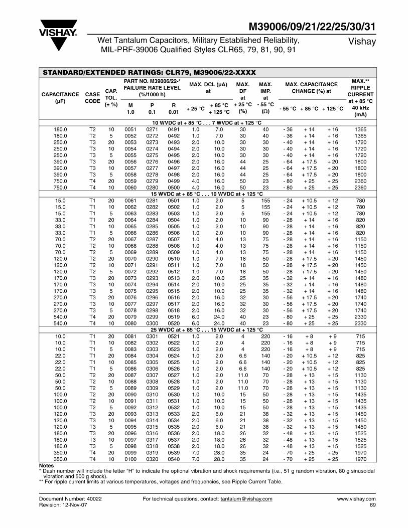
Document Number: 40022 For technical questions, contact: [email protected] www.vishay.comRevision: 12-Nov-07 69
M39006/09/21/22/25/30/31Wet Tantalum Capacitors, Military Established Reliability,MIL-PRF-39006 Qualified Styles CLR65, 79, 81, 90, 91
Vishay
STANDARD/EXTENDED RATINGS: CLR79, M39006/22-XXXX
CAPACITANCE (µF)
CASE CODE
CAP. TOL. (± %)
PART NO. M39006/22-*FAILURE RATE LEVEL
(%/1000 h)
MAX. DCL (µA)at
MAX. DFat
+ 25 °C(%)
MAX. IMP.at
- 55 °C()
MAX. CAPACITANCE CHANGE (%) at
MAX.**RIPPLE
CURRENT at + 85 °C
40 kHz (mA)
M1.0
P0.1
R0.01
+ 25 °C+ 85 °C
+ 125 °C- 55 °C + 85 °C + 125 °C
10 WVDC at + 85 °C . . . 7 WVDC at + 125 °C 180.0 T2 10 0051 0271 0491 1.0 7.0 30 40 - 36 + 14 + 16 1365 180.0 T2 5 0052 0272 0492 1.0 7.0 30 40 - 36 + 14 + 16 1365 250.0 T3 20 0053 0273 0493 2.0 10.0 30 30 - 40 + 14 + 16 1720 250.0 T3 10 0054 0274 0494 2.0 10.0 30 30 - 40 + 14 + 16 1720 250.0 T3 5 0055 0275 0495 2.0 10.0 30 30 - 40 + 14 + 16 1720 390.0 T3 20 0056 0276 0496 2.0 16.0 44 25 - 64 + 17.5 + 20 1800 390.0 T3 10 0057 0277 0497 2.0 16.0 44 25 - 64 + 17.5 + 20 1800 390.0 T3 5 0058 0278 0498 2.0 16.0 44 25 - 64 + 17.5 + 20 1800 750.0 T4 20 0059 0279 0499 4.0 16.0 50 23 - 80 + 25 + 25 2360 750.0 T4 10 0060 0280 0500 4.0 16.0 50 23 - 80 + 25 + 25 2360
15 WVDC at + 85 °C . . . 10 WVDC at + 125 °C 15.0 T1 20 0061 0281 0501 1.0 2.0 5 155 - 24 + 10.5 + 12 780 15.0 T1 10 0062 0282 0502 1.0 2.0 5 155 - 24 + 10.5 + 12 780 15.0 T1 5 0063 0283 0503 1.0 2.0 5 155 - 24 + 10.5 + 12 780 33.0 T1 20 0064 0284 0504 1.0 2.0 10 90 - 28 + 14 + 16 820 33.0 T1 10 0065 0285 0505 1.0 2.0 10 90 - 28 + 14 + 16 820 33.0 T1 5 0066 0286 0506 1.0 2.0 10 90 - 28 + 14 + 16 820 70.0 T2 20 0067 0287 0507 1.0 4.0 13 75 - 28 + 14 + 16 1150 70.0 T2 10 0068 0288 0508 1.0 4.0 13 75 - 28 + 14 + 16 1150 70.0 T2 5 0069 0289 0509 1.0 4.0 13 75 - 28 + 14 + 16 1150 120.0 T2 20 0070 0290 0510 1.0 7.0 18 50 - 28 + 17.5 + 20 1450 120.0 T2 10 0071 0291 0511 1.0 7.0 18 50 - 28 + 17.5 + 20 1450 120.0 T2 5 0072 0292 0512 1.0 7.0 18 50 - 28 + 17.5 + 20 1450 170.0 T3 20 0073 0293 0513 2.0 10.0 25 35 - 32 + 14 + 16 1480 170.0 T3 10 0074 0294 0514 2.0 10.0 25 35 - 32 + 14 + 16 1480 170.0 T3 5 0075 0295 0515 2.0 10.0 25 35 - 32 + 14 + 16 1480 270.0 T3 20 0076 0296 0516 2.0 16.0 32 30 - 56 + 17.5 + 20 1740 270.0 T3 10 0077 0297 0517 2.0 16.0 32 30 - 56 + 17.5 + 20 1740 270.0 T3 5 0078 0298 0518 2.0 16.0 32 30 - 56 + 17.5 + 20 1740 540.0 T4 20 0079 0299 0519 6.0 24.0 40 23 - 80 + 25 + 25 2330 540.0 T4 10 0080 0300 0520 6.0 24.0 40 23 - 80 + 25 + 25 2330
25 WVDC at + 85 °C . . . 15 WVDC at + 125 °C 10.0 T1 20 0081 0301 0521 1.0 2.0 4 220 - 16 + 8 + 9 715 10.0 T1 10 0082 0302 0522 1.0 2.0 4 220 - 16 + 8 + 9 715 10.0 T1 5 0083 0303 0523 1.0 2.0 4 220 - 16 + 8 + 9 715 22.0 T1 20 0084 0304 0524 1.0 2.0 6.6 140 - 20 + 10.5 + 12 825 22.0 T1 10 0085 0305 0525 1.0 2.0 6.6 140 - 20 + 10.5 + 12 825 22.0 T1 5 0086 0306 0526 1.0 2.0 6.6 140 - 20 + 10.5 + 12 825 50.0 T2 20 0087 0307 0527 1.0 2.0 11.0 70 - 28 + 13 + 15 1130 50.0 T2 10 0088 0308 0528 1.0 2.0 11.0 70 - 28 + 13 + 15 1130 50.0 T2 5 0089 0309 0529 1.0 2.0 11.0 70 - 28 + 13 + 15 1130 100.0 T2 20 0090 0310 0530 1.0 10.0 15 50 - 28 + 13 + 15 1435 100.0 T2 10 0091 0311 0531 1.0 10.0 15 50 - 28 + 13 + 15 1435 100.0 T2 5 0092 0312 0532 1.0 10.0 15 50 - 28 + 13 + 15 1435 120.0 T3 20 0093 0313 0533 2.0 6.0 21 38 - 32 + 13 + 15 1450 120.0 T3 10 0094 0314 0534 2.0 6.0 21 38 - 32 + 13 + 15 1450 120.0 T3 5 0095 0315 0535 2.0 6.0 21 38 - 32 + 13 + 15 1450 180.0 T3 20 0096 0316 0536 2.0 18.0 26 32 - 48 + 13 + 15 1525 180.0 T3 10 0097 0317 0537 2.0 18.0 26 32 - 48 + 13 + 15 1525 180.0 T3 5 0098 0318 0538 2.0 18.0 26 32 - 48 + 13 + 15 1525 350.0 T4 20 0099 0319 0539 7.0 28.0 35 24 - 70 + 25 + 25 1970 350.0 T4 10 0100 0320 0540 7.0 28.0 35 24 - 70 + 25 + 25 1970
Notes * Dash number will include the letter “H” to indicate the optional vibration and shock requirements (i.e., 51 g random vibration, 80 g sinusoidal
vibration and 500 g shock).** For ripple current limits at various temperatures, voltages and frequencies, see Ripple Current Table.
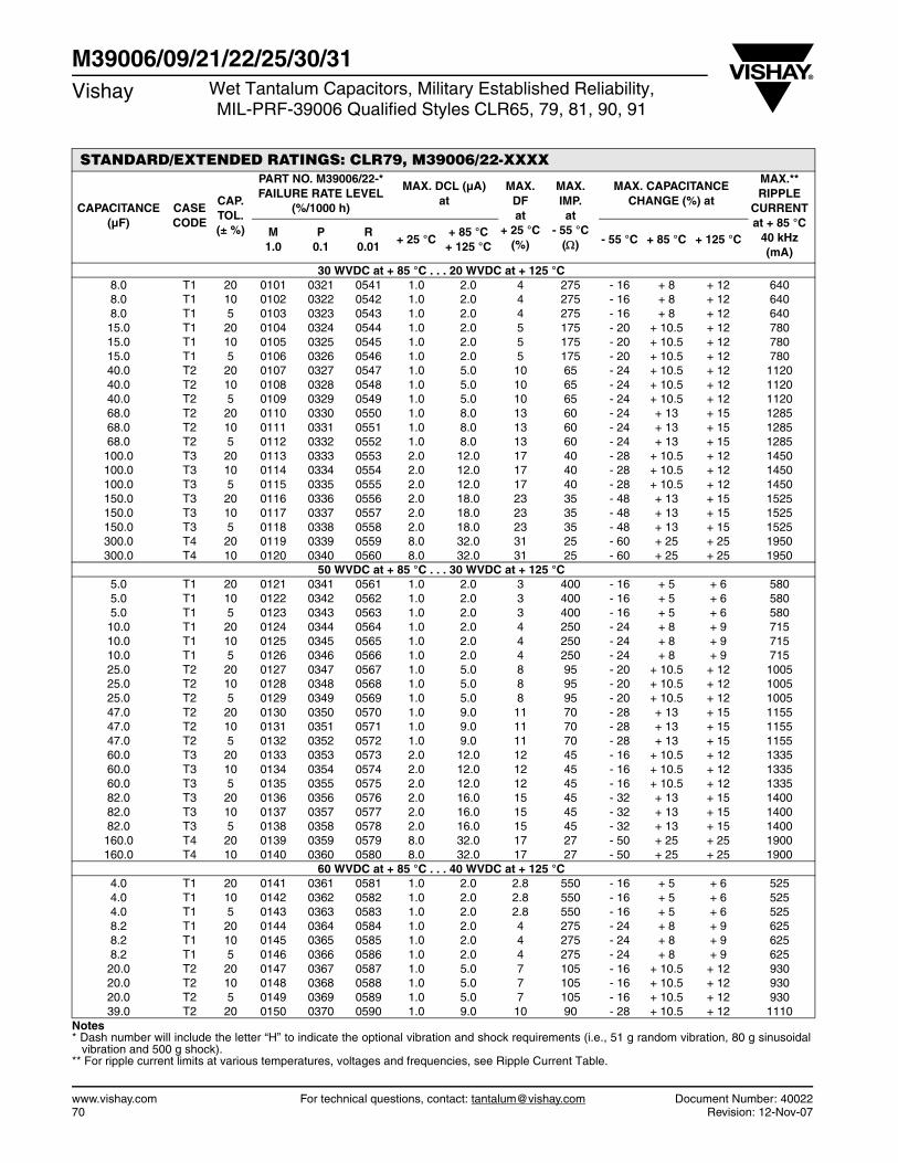
www.vishay.com For technical questions, contact: [email protected] Document Number: 4002270 Revision: 12-Nov-07
M39006/09/21/22/25/30/31Vishay Wet Tantalum Capacitors, Military Established Reliability,
MIL-PRF-39006 Qualified Styles CLR65, 79, 81, 90, 91
STANDARD/EXTENDED RATINGS: CLR79, M39006/22-XXXX
CAPACITANCE (µF)
CASE CODE
CAP. TOL. (± %)
PART NO. M39006/22-*FAILURE RATE LEVEL
(%/1000 h)
MAX. DCL (µA)at
MAX. DFat
+ 25 °C(%)
MAX. IMP.at
- 55 °C()
MAX. CAPACITANCE CHANGE (%) at
MAX.**RIPPLE
CURRENT at + 85 °C
40 kHz (mA)
M1.0
P0.1
R0.01
+ 25 °C+ 85 °C
+ 125 °C- 55 °C + 85 °C + 125 °C
30 WVDC at + 85 °C . . . 20 WVDC at + 125 °C 8.0 T1 20 0101 0321 0541 1.0 2.0 4 275 - 16 + 8 + 12 640 8.0 T1 10 0102 0322 0542 1.0 2.0 4 275 - 16 + 8 + 12 640 8.0 T1 5 0103 0323 0543 1.0 2.0 4 275 - 16 + 8 + 12 640 15.0 T1 20 0104 0324 0544 1.0 2.0 5 175 - 20 + 10.5 + 12 780 15.0 T1 10 0105 0325 0545 1.0 2.0 5 175 - 20 + 10.5 + 12 780 15.0 T1 5 0106 0326 0546 1.0 2.0 5 175 - 20 + 10.5 + 12 780 40.0 T2 20 0107 0327 0547 1.0 5.0 10 65 - 24 + 10.5 + 12 1120 40.0 T2 10 0108 0328 0548 1.0 5.0 10 65 - 24 + 10.5 + 12 1120 40.0 T2 5 0109 0329 0549 1.0 5.0 10 65 - 24 + 10.5 + 12 1120 68.0 T2 20 0110 0330 0550 1.0 8.0 13 60 - 24 + 13 + 15 1285 68.0 T2 10 0111 0331 0551 1.0 8.0 13 60 - 24 + 13 + 15 1285 68.0 T2 5 0112 0332 0552 1.0 8.0 13 60 - 24 + 13 + 15 1285 100.0 T3 20 0113 0333 0553 2.0 12.0 17 40 - 28 + 10.5 + 12 1450 100.0 T3 10 0114 0334 0554 2.0 12.0 17 40 - 28 + 10.5 + 12 1450 100.0 T3 5 0115 0335 0555 2.0 12.0 17 40 - 28 + 10.5 + 12 1450 150.0 T3 20 0116 0336 0556 2.0 18.0 23 35 - 48 + 13 + 15 1525 150.0 T3 10 0117 0337 0557 2.0 18.0 23 35 - 48 + 13 + 15 1525 150.0 T3 5 0118 0338 0558 2.0 18.0 23 35 - 48 + 13 + 15 1525 300.0 T4 20 0119 0339 0559 8.0 32.0 31 25 - 60 + 25 + 25 1950 300.0 T4 10 0120 0340 0560 8.0 32.0 31 25 - 60 + 25 + 25 1950
50 WVDC at + 85 °C . . . 30 WVDC at + 125 °C 5.0 T1 20 0121 0341 0561 1.0 2.0 3 400 - 16 + 5 + 6 580 5.0 T1 10 0122 0342 0562 1.0 2.0 3 400 - 16 + 5 + 6 580 5.0 T1 5 0123 0343 0563 1.0 2.0 3 400 - 16 + 5 + 6 580 10.0 T1 20 0124 0344 0564 1.0 2.0 4 250 - 24 + 8 + 9 715 10.0 T1 10 0125 0345 0565 1.0 2.0 4 250 - 24 + 8 + 9 715 10.0 T1 5 0126 0346 0566 1.0 2.0 4 250 - 24 + 8 + 9 715 25.0 T2 20 0127 0347 0567 1.0 5.0 8 95 - 20 + 10.5 + 12 1005 25.0 T2 10 0128 0348 0568 1.0 5.0 8 95 - 20 + 10.5 + 12 1005 25.0 T2 5 0129 0349 0569 1.0 5.0 8 95 - 20 + 10.5 + 12 1005 47.0 T2 20 0130 0350 0570 1.0 9.0 11 70 - 28 + 13 + 15 1155 47.0 T2 10 0131 0351 0571 1.0 9.0 11 70 - 28 + 13 + 15 1155 47.0 T2 5 0132 0352 0572 1.0 9.0 11 70 - 28 + 13 + 15 1155 60.0 T3 20 0133 0353 0573 2.0 12.0 12 45 - 16 + 10.5 + 12 1335 60.0 T3 10 0134 0354 0574 2.0 12.0 12 45 - 16 + 10.5 + 12 1335 60.0 T3 5 0135 0355 0575 2.0 12.0 12 45 - 16 + 10.5 + 12 1335 82.0 T3 20 0136 0356 0576 2.0 16.0 15 45 - 32 + 13 + 15 1400 82.0 T3 10 0137 0357 0577 2.0 16.0 15 45 - 32 + 13 + 15 1400 82.0 T3 5 0138 0358 0578 2.0 16.0 15 45 - 32 + 13 + 15 1400 160.0 T4 20 0139 0359 0579 8.0 32.0 17 27 - 50 + 25 + 25 1900 160.0 T4 10 0140 0360 0580 8.0 32.0 17 27 - 50 + 25 + 25 1900
60 WVDC at + 85 °C . . . 40 WVDC at + 125 °C 4.0 T1 20 0141 0361 0581 1.0 2.0 2.8 550 - 16 + 5 + 6 525 4.0 T1 10 0142 0362 0582 1.0 2.0 2.8 550 - 16 + 5 + 6 525 4.0 T1 5 0143 0363 0583 1.0 2.0 2.8 550 - 16 + 5 + 6 525 8.2 T1 20 0144 0364 0584 1.0 2.0 4 275 - 24 + 8 + 9 625 8.2 T1 10 0145 0365 0585 1.0 2.0 4 275 - 24 + 8 + 9 625 8.2 T1 5 0146 0366 0586 1.0 2.0 4 275 - 24 + 8 + 9 625 20.0 T2 20 0147 0367 0587 1.0 5.0 7 105 - 16 + 10.5 + 12 930 20.0 T2 10 0148 0368 0588 1.0 5.0 7 105 - 16 + 10.5 + 12 930 20.0 T2 5 0149 0369 0589 1.0 5.0 7 105 - 16 + 10.5 + 12 930 39.0 T2 20 0150 0370 0590 1.0 9.0 10 90 - 28 + 10.5 + 12 1110
Notes * Dash number will include the letter “H” to indicate the optional vibration and shock requirements (i.e., 51 g random vibration, 80 g sinusoidal
vibration and 500 g shock).** For ripple current limits at various temperatures, voltages and frequencies, see Ripple Current Table.
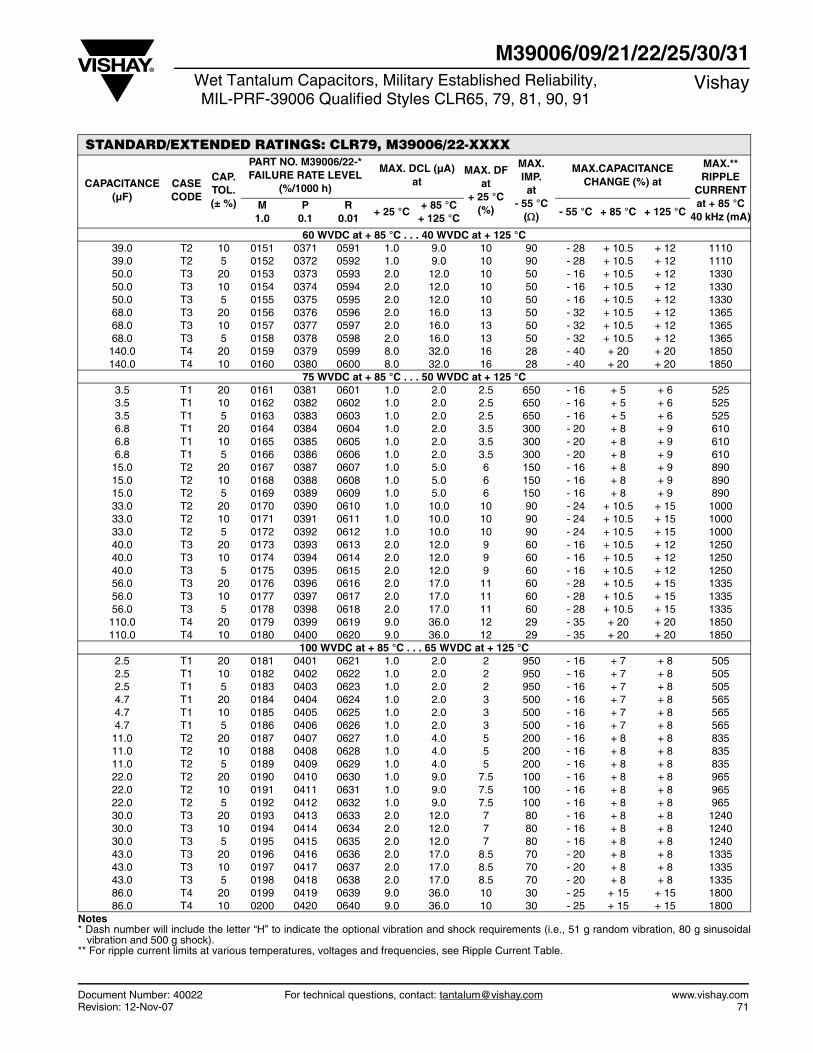
Document Number: 40022 For technical questions, contact: [email protected] www.vishay.comRevision: 12-Nov-07 71
M39006/09/21/22/25/30/31Wet Tantalum Capacitors, Military Established Reliability,MIL-PRF-39006 Qualified Styles CLR65, 79, 81, 90, 91
Vishay
STANDARD/EXTENDED RATINGS: CLR79, M39006/22-XXXX
CAPACITANCE (µF)
CASE CODE
CAP. TOL. (± %)
PART NO. M39006/22-*FAILURE RATE LEVEL
(%/1000 h)
MAX. DCL (µA)at
MAX. DFat
+ 25 °C(%)
MAX. IMP.at
- 55 °C()
MAX.CAPACITANCE CHANGE (%) at
MAX.**RIPPLE
CURRENT at + 85 °C
40 kHz (mA)M
1.0P
0.1R
0.01+ 25 °C
+ 85 °C+ 125 °C
- 55 °C + 85 °C + 125 °C
60 WVDC at + 85 °C . . . 40 WVDC at + 125 °C 39.0 T2 10 0151 0371 0591 1.0 9.0 10 90 - 28 + 10.5 + 12 1110 39.0 T2 5 0152 0372 0592 1.0 9.0 10 90 - 28 + 10.5 + 12 1110 50.0 T3 20 0153 0373 0593 2.0 12.0 10 50 - 16 + 10.5 + 12 1330 50.0 T3 10 0154 0374 0594 2.0 12.0 10 50 - 16 + 10.5 + 12 1330 50.0 T3 5 0155 0375 0595 2.0 12.0 10 50 - 16 + 10.5 + 12 1330 68.0 T3 20 0156 0376 0596 2.0 16.0 13 50 - 32 + 10.5 + 12 1365 68.0 T3 10 0157 0377 0597 2.0 16.0 13 50 - 32 + 10.5 + 12 1365 68.0 T3 5 0158 0378 0598 2.0 16.0 13 50 - 32 + 10.5 + 12 1365 140.0 T4 20 0159 0379 0599 8.0 32.0 16 28 - 40 + 20 + 20 1850 140.0 T4 10 0160 0380 0600 8.0 32.0 16 28 - 40 + 20 + 20 1850
75 WVDC at + 85 °C . . . 50 WVDC at + 125 °C 3.5 T1 20 0161 0381 0601 1.0 2.0 2.5 650 - 16 + 5 + 6 525 3.5 T1 10 0162 0382 0602 1.0 2.0 2.5 650 - 16 + 5 + 6 525 3.5 T1 5 0163 0383 0603 1.0 2.0 2.5 650 - 16 + 5 + 6 525 6.8 T1 20 0164 0384 0604 1.0 2.0 3.5 300 - 20 + 8 + 9 610 6.8 T1 10 0165 0385 0605 1.0 2.0 3.5 300 - 20 + 8 + 9 610 6.8 T1 5 0166 0386 0606 1.0 2.0 3.5 300 - 20 + 8 + 9 610 15.0 T2 20 0167 0387 0607 1.0 5.0 6 150 - 16 + 8 + 9 890 15.0 T2 10 0168 0388 0608 1.0 5.0 6 150 - 16 + 8 + 9 890 15.0 T2 5 0169 0389 0609 1.0 5.0 6 150 - 16 + 8 + 9 890 33.0 T2 20 0170 0390 0610 1.0 10.0 10 90 - 24 + 10.5 + 15 1000 33.0 T2 10 0171 0391 0611 1.0 10.0 10 90 - 24 + 10.5 + 15 1000 33.0 T2 5 0172 0392 0612 1.0 10.0 10 90 - 24 + 10.5 + 15 1000 40.0 T3 20 0173 0393 0613 2.0 12.0 9 60 - 16 + 10.5 + 12 1250 40.0 T3 10 0174 0394 0614 2.0 12.0 9 60 - 16 + 10.5 + 12 1250 40.0 T3 5 0175 0395 0615 2.0 12.0 9 60 - 16 + 10.5 + 12 1250 56.0 T3 20 0176 0396 0616 2.0 17.0 11 60 - 28 + 10.5 + 15 1335 56.0 T3 10 0177 0397 0617 2.0 17.0 11 60 - 28 + 10.5 + 15 1335 56.0 T3 5 0178 0398 0618 2.0 17.0 11 60 - 28 + 10.5 + 15 1335 110.0 T4 20 0179 0399 0619 9.0 36.0 12 29 - 35 + 20 + 20 1850 110.0 T4 10 0180 0400 0620 9.0 36.0 12 29 - 35 + 20 + 20 1850
100 WVDC at + 85 °C . . . 65 WVDC at + 125 °C 2.5 T1 20 0181 0401 0621 1.0 2.0 2 950 - 16 + 7 + 8 505 2.5 T1 10 0182 0402 0622 1.0 2.0 2 950 - 16 + 7 + 8 505 2.5 T1 5 0183 0403 0623 1.0 2.0 2 950 - 16 + 7 + 8 505 4.7 T1 20 0184 0404 0624 1.0 2.0 3 500 - 16 + 7 + 8 565 4.7 T1 10 0185 0405 0625 1.0 2.0 3 500 - 16 + 7 + 8 565 4.7 T1 5 0186 0406 0626 1.0 2.0 3 500 - 16 + 7 + 8 565 11.0 T2 20 0187 0407 0627 1.0 4.0 5 200 - 16 + 8 + 8 835 11.0 T2 10 0188 0408 0628 1.0 4.0 5 200 - 16 + 8 + 8 835 11.0 T2 5 0189 0409 0629 1.0 4.0 5 200 - 16 + 8 + 8 835 22.0 T2 20 0190 0410 0630 1.0 9.0 7.5 100 - 16 + 8 + 8 965 22.0 T2 10 0191 0411 0631 1.0 9.0 7.5 100 - 16 + 8 + 8 965 22.0 T2 5 0192 0412 0632 1.0 9.0 7.5 100 - 16 + 8 + 8 965 30.0 T3 20 0193 0413 0633 2.0 12.0 7 80 - 16 + 8 + 8 1240 30.0 T3 10 0194 0414 0634 2.0 12.0 7 80 - 16 + 8 + 8 1240 30.0 T3 5 0195 0415 0635 2.0 12.0 7 80 - 16 + 8 + 8 1240 43.0 T3 20 0196 0416 0636 2.0 17.0 8.5 70 - 20 + 8 + 8 1335 43.0 T3 10 0197 0417 0637 2.0 17.0 8.5 70 - 20 + 8 + 8 1335 43.0 T3 5 0198 0418 0638 2.0 17.0 8.5 70 - 20 + 8 + 8 1335 86.0 T4 20 0199 0419 0639 9.0 36.0 10 30 - 25 + 15 + 15 1800 86.0 T4 10 0200 0420 0640 9.0 36.0 10 30 - 25 + 15 + 15 1800
Notes * Dash number will include the letter “H” to indicate the optional vibration and shock requirements (i.e., 51 g random vibration, 80 g sinusoidal
vibration and 500 g shock).** For ripple current limits at various temperatures, voltages and frequencies, see Ripple Current Table.
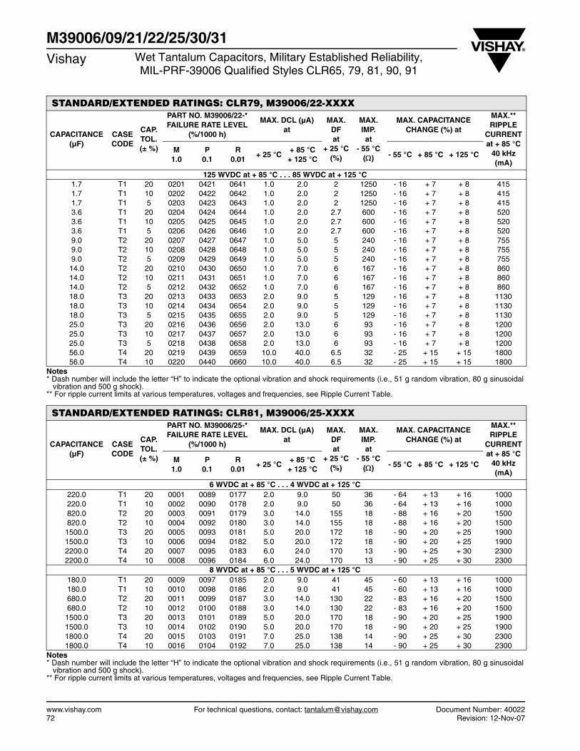
www.vishay.com For technical questions, contact: [email protected] Document Number: 4002272 Revision: 12-Nov-07
M39006/09/21/22/25/30/31Vishay Wet Tantalum Capacitors, Military Established Reliability,
MIL-PRF-39006 Qualified Styles CLR65, 79, 81, 90, 91
STANDARD/EXTENDED RATINGS: CLR79, M39006/22-XXXX
CAPACITANCE (µF)
CASE CODE
CAP. TOL. (± %)
PART NO. M39006/22-*FAILURE RATE LEVEL
(%/1000 h)
MAX. DCL (µA)at
MAX. DFat
+ 25 °C(%)
MAX. IMP.at
- 55 °C()
MAX. CAPACITANCE CHANGE (%) at
MAX.**RIPPLE
CURRENT at + 85 °C
40 kHz (mA)
M1.0
P0.1
R0.01
+ 25 °C+ 85 °C
+ 125 °C- 55 °C + 85 °C + 125 °C
125 WVDC at + 85 °C . . . 85 WVDC at + 125 °C 1.7 T1 20 0201 0421 0641 1.0 2.0 2 1250 - 16 + 7 + 8 415 1.7 T1 10 0202 0422 0642 1.0 2.0 2 1250 - 16 + 7 + 8 415 1.7 T1 5 0203 0423 0643 1.0 2.0 2 1250 - 16 + 7 + 8 415 3.6 T1 20 0204 0424 0644 1.0 2.0 2.7 600 - 16 + 7 + 8 520 3.6 T1 10 0205 0425 0645 1.0 2.0 2.7 600 - 16 + 7 + 8 520 3.6 T1 5 0206 0426 0646 1.0 2.0 2.7 600 - 16 + 7 + 8 520 9.0 T2 20 0207 0427 0647 1.0 5.0 5 240 - 16 + 7 + 8 755 9.0 T2 10 0208 0428 0648 1.0 5.0 5 240 - 16 + 7 + 8 755 9.0 T2 5 0209 0429 0649 1.0 5.0 5 240 - 16 + 7 + 8 755 14.0 T2 20 0210 0430 0650 1.0 7.0 6 167 - 16 + 7 + 8 860 14.0 T2 10 0211 0431 0651 1.0 7.0 6 167 - 16 + 7 + 8 860 14.0 T2 5 0212 0432 0652 1.0 7.0 6 167 - 16 + 7 + 8 860 18.0 T3 20 0213 0433 0653 2.0 9.0 5 129 - 16 + 7 + 8 1130 18.0 T3 10 0214 0434 0654 2.0 9.0 5 129 - 16 + 7 + 8 1130 18.0 T3 5 0215 0435 0655 2.0 9.0 5 129 - 16 + 7 + 8 1130 25.0 T3 20 0216 0436 0656 2.0 13.0 6 93 - 16 + 7 + 8 1200 25.0 T3 10 0217 0437 0657 2.0 13.0 6 93 - 16 + 7 + 8 1200 25.0 T3 5 0218 0438 0658 2.0 13.0 6 93 - 16 + 7 + 8 1200 56.0 T4 20 0219 0439 0659 10.0 40.0 6.5 32 - 25 + 15 + 15 1800 56.0 T4 10 0220 0440 0660 10.0 40.0 6.5 32 - 25 + 15 + 15 1800
Notes* Dash number will include the letter “H” to indicate the optional vibration and shock requirements (i.e., 51 g random vibration, 80 g sinusoidal
vibration and 500 g shock).** For ripple current limits at various temperatures, voltages and frequencies, see Ripple Current Table.
STANDARD/EXTENDED RATINGS: CLR81, M39006/25-XXXX
CAPACITANCE (µF)
CASE CODE
CAP. TOL. (± %)
PART NO. M39006/25-*FAILURE RATE LEVEL
(%/1000 h)
MAX. DCL (µA)at
MAX. DFat
+ 25 °C(%)
MAX. IMP.at
- 55 °C()
MAX. CAPACITANCE CHANGE (%) at
MAX.**RIPPLE
CURRENT at + 85 °C
40 kHz (mA)
M1.0
P0.1
R0.01
+ 25 °C+ 85 °C
+ 125 °C- 55 °C + 85 °C + 125 °C
6 WVDC at + 85 °C . . . 4 WVDC at + 125 °C 220.0 T1 20 0001 0089 0177 2.0 9.0 50 36 - 64 + 13 + 16 1000 220.0 T1 10 0002 0090 0178 2.0 9.0 50 36 - 64 + 13 + 16 1000 820.0 T2 20 0003 0091 0179 3.0 14.0 155 18 - 88 + 16 + 20 1500 820.0 T2 10 0004 0092 0180 3.0 14.0 155 18 - 88 + 16 + 20 1500
1500.0 T3 20 0005 0093 0181 5.0 20.0 172 18 - 90 + 20 + 25 1900 1500.0 T3 10 0006 0094 0182 5.0 20.0 172 18 - 90 + 20 + 25 1900 2200.0 T4 20 0007 0095 0183 6.0 24.0 170 13 - 90 + 25 + 30 2300 2200.0 T4 10 0008 0096 0184 6.0 24.0 170 13 - 90 + 25 + 30 2300
8 WVDC at + 85 °C . . . 5 WVDC at + 125 °C 180.0 T1 20 0009 0097 0185 2.0 9.0 41 45 - 60 + 13 + 16 1000 180.0 T1 10 0010 0098 0186 2.0 9.0 41 45 - 60 + 13 + 16 1000 680.0 T2 20 0011 0099 0187 3.0 14.0 130 22 - 83 + 16 + 20 1500 680.0 T2 10 0012 0100 0188 3.0 14.0 130 22 - 83 + 16 + 20 1500
1500.0 T3 20 0013 0101 0189 5.0 20.0 170 18 - 90 + 20 + 25 1900 1500.0 T3 10 0014 0102 0190 5.0 20.0 170 18 - 90 + 20 + 25 1900 1800.0 T4 20 0015 0103 0191 7.0 25.0 138 14 - 90 + 25 + 30 2300 1800.0 T4 10 0016 0104 0192 7.0 25.0 138 14 - 90 + 25 + 30 2300
Notes* Dash number will include the letter “H” to indicate the optional vibration and shock requirements (i.e., 51 g random vibration, 80 g sinusoidal
vibration and 500 g shock).** For ripple current limits at various temperatures, voltages and frequencies, see Ripple Current Table.
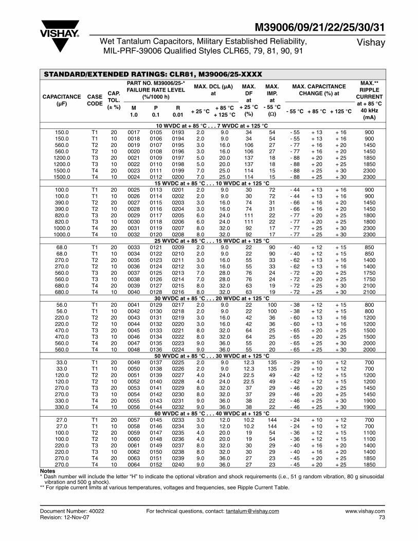
Document Number: 40022 For technical questions, contact: [email protected] www.vishay.comRevision: 12-Nov-07 73
M39006/09/21/22/25/30/31Wet Tantalum Capacitors, Military Established Reliability,MIL-PRF-39006 Qualified Styles CLR65, 79, 81, 90, 91
Vishay
STANDARD/EXTENDED RATINGS: CLR81, M39006/25-XXXX
CAPACITANCE (µF)
CASE CODE
CAP. TOL. (± %)
PART NO. M39006/25-*FAILURE RATE LEVEL
(%/1000 h)
MAX. DCL (µA)at
MAX. DFat
+ 25 °C(%)
MAX. IMP.at
- 55 °C()
MAX. CAPACITANCE CHANGE (%) at
MAX.**RIPPLE
CURRENT at + 85 °C
40 kHz (mA)
M1.0
P0.1
R0.01
+ 25 °C+ 85 °C
+ 125 °C- 55 °C + 85 °C + 125 °C
10 WVDC at + 85 °C . . . 7 WVDC at + 125 °C 150.0 T1 20 0017 0105 0193 2.0 9.0 34 54 - 55 + 13 + 16 900 150.0 T1 10 0018 0106 0194 2.0 9.0 34 54 - 55 + 13 + 16 900 560.0 T2 20 0019 0107 0195 3.0 16.0 106 27 - 77 + 16 + 20 1450 560.0 T2 10 0020 0108 0196 3.0 16.0 106 27 - 77 + 16 + 20 1450 1200.0 T3 20 0021 0109 0197 5.0 20.0 137 18 - 88 + 20 + 25 1850 1200.0 T3 10 0022 0110 0198 5.0 20.0 137 18 - 88 + 20 + 25 1850 1500.0 T4 20 0023 0111 0199 7.0 25.0 114 15 - 88 + 25 + 30 2300 1500.0 T4 10 0024 0112 0200 7.0 25.0 114 15 - 88 + 25 + 30 2300
15 WVDC at + 85 °C . . . 10 WVDC at + 125 °C 100.0 T1 20 0025 0113 0201 2.0 9.0 30 72 - 44 + 13 + 16 900 100.0 T1 10 0026 0114 0202 2.0 9.0 30 72 - 44 + 13 + 16 900 390.0 T2 20 0027 0115 0203 3.0 16.0 74 31 - 66 + 16 + 20 1450 390.0 T2 10 0028 0116 0204 3.0 16.0 74 31 - 66 + 16 + 20 1450 820.0 T3 20 0029 0117 0205 6.0 24.0 111 22 - 77 + 20 + 25 1800 820.0 T3 10 0030 0118 0206 6.0 24.0 111 22 - 77 + 20 + 25 1800 1000.0 T4 20 0031 0119 0207 8.0 32.0 92 17 - 77 + 25 + 30 2300 1000.0 T4 10 0032 0120 0208 8.0 32.0 92 17 - 77 + 25 + 30 2300
25 WVDC at + 85 °C . . . 15 WVDC at + 125 °C 68.0 T1 20 0033 0121 0209 2.0 9.0 22 90 - 40 + 12 + 15 850 68.0 T1 10 0034 0122 0210 2.0 9.0 22 90 - 40 + 12 + 15 850 270.0 T2 20 0035 0123 0211 3.0 16.0 55 33 - 62 + 13 + 16 1400 270.0 T2 10 0036 0124 0212 3.0 16.0 55 33 - 62 + 13 + 16 1400 560.0 T3 20 0037 0125 0213 7.0 28.0 76 24 - 72 + 20 + 25 1750 560.0 T3 10 0038 0126 0214 7.0 28.0 76 24 - 72 + 20 + 25 1750 680.0 T4 20 0039 0127 0215 8.0 32.0 63 19 - 72 + 25 + 30 2100 680.0 T4 10 0040 0128 0216 8.0 32.0 63 19 - 72 + 25 + 30 2100
30 WVDC at + 85 °C . . . 20 WVDC at + 125 °C 56.0 T1 20 0041 0129 0217 2.0 9.0 22 100 - 38 + 12 + 15 800 56.0 T1 10 0042 0130 0218 2.0 9.0 22 100 - 38 + 12 + 15 800 220.0 T2 20 0043 0131 0219 3.0 16.0 42 36 - 60 + 13 + 16 1200 220.0 T2 10 0044 0132 0220 3.0 16.0 42 36 - 60 + 13 + 16 1200 470.0 T3 20 0045 0133 0221 8.0 32.0 64 25 - 65 + 20 + 25 1500 470.0 T3 10 0046 0134 0222 8.0 32.0 64 25 - 65 + 20 + 25 1500 560.0 T4 20 0047 0135 0223 9.0 36.0 55 20 - 65 + 25 + 30 2000 560.0 T4 10 0048 0136 0224 9.0 36.0 55 20 - 65 + 25 + 30 2000
50 WVDC at + 85 °C . . . 30 WVDC at + 125 °C 33.0 T1 20 0049 0137 0225 2.0 9.0 12.3 135 - 29 + 10 + 12 700 33.0 T1 10 0050 0138 0226 2.0 9.0 12.3 135 - 29 + 10 + 12 700 120.0 T2 20 0051 0139 0227 4.0 24.0 22.5 49 - 42 + 12 + 15 1200 120.0 T2 10 0052 0140 0228 4.0 24.0 22.5 49 - 42 + 12 + 15 1200 270.0 T3 20 0053 0141 0229 8.0 32.0 37 29 - 46 + 20 + 25 1450 270.0 T3 10 0054 0142 0230 8.0 32.0 37 29 - 46 + 20 + 25 1450 330.0 T4 20 0055 0143 0231 9.0 36.0 38 22 - 46 + 25 + 30 1900 330.0 T4 10 0056 0144 0232 9.0 36.0 38 22 - 46 + 25 + 30 1900
60 WVDC at + 85 °C . . . 40 WVDC at + 125 °C 27.0 T1 20 0057 0145 0233 3.0 12.0 10.2 144 - 24 + 10 + 12 700 27.0 T1 10 0058 0146 0234 3.0 12.0 10.2 144 - 24 + 10 + 12 700 100.0 T2 20 0059 0147 0235 4.0 20.0 19 54 - 36 + 12 + 15 1100 100.0 T2 10 0060 0148 0236 4.0 20.0 19 54 - 36 + 12 + 15 1100 220.0 T3 20 0061 0149 0237 8.0 32.0 30 29 - 40 + 16 + 20 1400 220.0 T3 10 0062 0150 0238 8.0 32.0 30 29 - 40 + 16 + 20 1400 270.0 T4 20 0063 0151 0239 9.0 36.0 27 23 - 45 + 20 + 25 1850 270.0 T4 10 0064 0152 0240 9.0 36.0 27 23 - 45 + 20 + 25 1850
Notes* Dash number will include the letter “H” to indicate the optional vibration and shock requirements (i.e., 51 g random vibration, 80 g sinusoidal
vibration and 500 g shock).** For ripple current limits at various temperatures, voltages and frequencies, see Ripple Current Table.

www.vishay.com For technical questions, contact: [email protected] Document Number: 4002274 Revision: 12-Nov-07
M39006/09/21/22/25/30/31Vishay Wet Tantalum Capacitors, Military Established Reliability,
MIL-PRF-39006 Qualified Styles CLR65, 79, 81, 90, 91
STANDARD/EXTENDED RATINGS: CLR81, M39006/25-XXXX
CAPACITANCE (µF)
CASE CODE
CAP. TOL. (± %)
PART NO. M39006/25-*FAILURE RATE LEVEL
(%/1000 h)
MAX. DCL (µA)at
MAX. DFat
+ 25 °C(%)
MAX. IMP.at
- 55 °C()
MAX.. CAPACITANCE CHANGE (%) at
MAX.**RIPPLE
CURRENT at + 85 °C
40 kHz (mA)
M1.0
P0.1
R0.01
+ 25 °C+ 85 °C
+ 125 °C- 55 °C + 85 °C + 125 °C
75 WVDC at + 85 °C . . . 50 WVDC at + 125 °C 22.0 T1 20 0065 0153 0241 3.0 12.0 8.5 157 - 19 + 10 + 12 600 22.0 T1 10 0066 0154 0242 3.0 12.0 8.5 157 - 19 + 10 + 12 600 82.0 T2 20 0067 0155 0243 4.0 24.0 15.2 63 - 30 + 12 + 15 1000 82.0 T2 10 0068 0156 0244 4.0 24.0 15.2 63 - 30 + 12 + 15 1000 180.0 T3 20 0069 0157 0245 9.0 36.0 24.4 30 - 35 + 16 + 20 1300 180.0 T3 10 0070 0158 0246 9.0 36.0 24.4 30 - 35 + 16 + 20 1300 220.0 T4 20 0071 0159 0247 10.0 40.0 37.0 24 - 40 + 20 + 25 1800 220.0 T4 10 0072 0160 0248 10.0 40.0 37.0 24 - 40 + 20 + 25 1800
100 WVDC at + 85 °C . . . 65 WVDC at + 125 °C 10.0 T1 20 0073 0161 0249 3.0 12.0 4.5 200 - 17 + 10 + 12 800 10.0 T1 10 0074 0162 0250 3.0 12.0 4.5 200 - 17 + 10 + 12 800 39.0 T2 20 0075 0163 0251 5.0 24.0 10.4 80 - 20 + 12 + 15 1300 39.0 T2 10 0076 0164 0252 5.0 24.0 10.4 80 - 20 + 12 + 15 1300 68.0 T3 20 0077 0165 0253 10.0 40.0 11.3 40 - 30 + 14 + 16 1600 68.0 T3 10 0078 0166 0254 10.0 40.0 11.3 40 - 30 + 14 + 16 1600 120.0 T4 20 0079 0167 0255 12.0 48.0 25 30 - 35 + 15 + 17 2000 120.0 T4 10 0080 0168 0256 12.0 48.0 25 30 - 35 + 15 + 17 2000
125 WVDC at + 85 °C . . . 85 WVDC at + 125 °C 6.8 T1 20 0081 0169 0257 3.0 12.0 6.0 300 - 14 + 10 + 12 700 6.8 T1 10 0082 0170 0258 3.0 12.0 6.0 300 - 14 + 10 + 12 700 27.0 T2 20 0083 0171 0259 5.0 24.0 7.2 90 - 18 + 12 + 15 1200 27.0 T2 10 0084 0172 0260 5.0 24.0 7.2 90 - 18 + 12 + 15 1200 47.0 T3 20 0085 0173 0261 10.0 40.0 7.9 50 - 26 + 14 + 16 1500 47.0 T3 10 0086 0174 0262 10.0 40.0 7.9 50 - 26 + 14 + 16 1500 82.0 T4 20 0087 0175 0263 12.0 48.0 17.4 32 - 30 + 15 + 17 1900 82.0 T4 10 0088 0176 0264 12.0 48.0 17.4 32 - 30 + 15 + 17 1900
Notes * Dash number will include the letter “H” to indicate the optional vibration and shock requirements (i.e., 51 g random vibration, 80 g sinusoidal
vibration and 500 g shock).** For ripple current limits at various temperatures, voltages and frequencies, see Ripple Current Table.
CLR79, CLR81 RIPPLE CURRENT MULTIPLIERS VS. FREQUENCY, TEMPERATURE AND APPLIED PEAK VOLTAGEFREQUENCY OF APPLIED RIPPLE
CURRENT120 Hz 800 Hz 1 kHz 10 kHz 40 kHz 100 kHz
AMBIENT STILL AIR
TEMP °C TEMP °C TEMP °C TEMP °C TEMP °C TEMP °C 55 85 105 125 55 85 105 125 55 85 105 125 55 85 105 125 55 85 105 125 55 85 105 125
% of APPLIED VOLTAGE
100 % 0.60 0.39 - - 0.71 0.43 - - 0.72 0.46 - - 0.88 0.55 - - 1.0 0.63 - - 1.1 0.69 - - 90 % 0.60 0.46 - - 0.71 0.55 - - 0.72 0.55 - - 0.88 0.67 - - 1.0 0.77 - - 1.1 0.85 - - 80 % 0.60 0.52 0.35 - 0.71 0.62 0.42 - 0.72 0.62 0.42 - 0.88 0.76 0.52 - 1.0 0.87 0.59 - 1.1 0.96 0.65 - 70 % 0.60 0.58 0.44 - 0.71 0.69 0.52 - 0.72 0.70 0.52 - 0.88 0.85 0.64 - 1.0 0.97 0.73 - 1.1 1.07 0.80 -
66 2/3 % 0.60 0.60 0.46 0.27 0.71 0.71 0.55 0.32 0.72 0.72 0.55 0.32 0.88 0.88 0.68 0.40 1.0 1.0 0.77 0.45 1.1 1.1 0.85 0.50
Notes
1. At + 125 °C the rated voltage of the capacitors decreases to 66 2/3 percent of the + 85 °C rated voltage.
2. The peak of the applied AC ripple voltage plus the applied DC voltage must not exceed the DC voltage rating of the capacitor eitherforward or reverse.
3. The ripple current listed represents a rating calculated using a maximum internal temperature rise (T) of + 50 °C at 40 kHz at + 85 °C ambient with a maximum peak rated voltage of 66 2/3 percent of the + 85 °C peak voltage rating.
4. The maximum allowable internal temperature rise (T) decreases linearly to a calculated + 10 °C rise at + 125 °C ambient.
5. The internal temperature rise is directly proportional to the equivalent series resistance of the capacitor and equivalent series resistance increases with decreasing frequency.
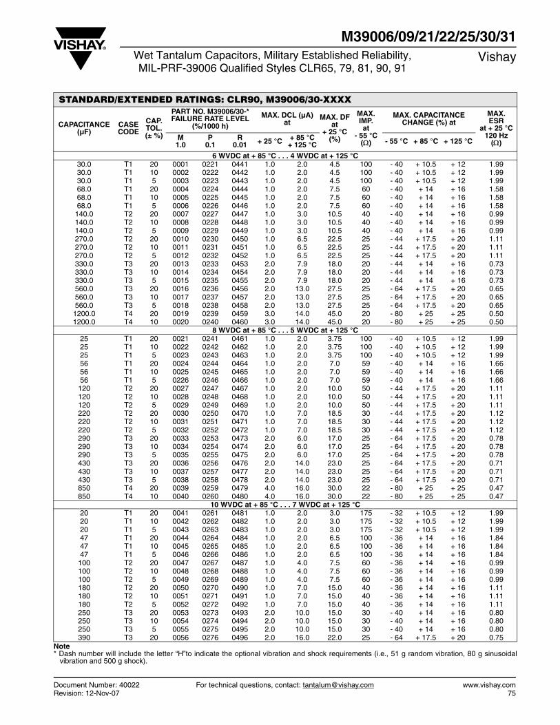
Document Number: 40022 For technical questions, contact: [email protected] www.vishay.comRevision: 12-Nov-07 75
M39006/09/21/22/25/30/31Wet Tantalum Capacitors, Military Established Reliability,MIL-PRF-39006 Qualified Styles CLR65, 79, 81, 90, 91
Vishay
STANDARD/EXTENDED RATINGS: CLR90, M39006/30-XXXX
CAPACITANCE (µF)
CASE CODE
CAP. TOL. (± %)
PART NO. M39006/30-*FAILURE RATE LEVEL
(%/1000 h)
MAX. DCL (µA)at
MAX. DFat
+ 25 °C(%)
MAX. IMP.at
- 55 °C()
MAX. CAPACITANCE CHANGE (%) at
MAX.ESR
at + 25 °C 120 Hz
()M
1.0P
0.1R
0.01 + 25 °C + 85 °C+ 125 °C - 55 °C + 85 °C + 125 °C
6 WVDC at + 85 °C . . . 4 WVDC at + 125 °C 30.0 T1 20 0001 0221 0441 1.0 2.0 4.5 100 - 40 + 10.5 + 12 1.99 30.0 T1 10 0002 0222 0442 1.0 2.0 4.5 100 - 40 + 10.5 + 12 1.99 30.0 T1 5 0003 0223 0443 1.0 2.0 4.5 100 - 40 + 10.5 + 12 1.99 68.0 T1 20 0004 0224 0444 1.0 2.0 7.5 60 - 40 + 14 + 16 1.58 68.0 T1 10 0005 0225 0445 1.0 2.0 7.5 60 - 40 + 14 + 16 1.58 68.0 T1 5 0006 0226 0446 1.0 2.0 7.5 60 - 40 + 14 + 16 1.58 140.0 T2 20 0007 0227 0447 1.0 3.0 10.5 40 - 40 + 14 + 16 0.99 140.0 T2 10 0008 0228 0448 1.0 3.0 10.5 40 - 40 + 14 + 16 0.99 140.0 T2 5 0009 0229 0449 1.0 3.0 10.5 40 - 40 + 14 + 16 0.99 270.0 T2 20 0010 0230 0450 1.0 6.5 22.5 25 - 44 + 17.5 + 20 1.11 270.0 T2 10 0011 0231 0451 1.0 6.5 22.5 25 - 44 + 17.5 + 20 1.11 270.0 T2 5 0012 0232 0452 1.0 6.5 22.5 25 - 44 + 17.5 + 20 1.11 330.0 T3 20 0013 0233 0453 2.0 7.9 18.0 20 - 44 + 14 + 16 0.73 330.0 T3 10 0014 0234 0454 2.0 7.9 18.0 20 - 44 + 14 + 16 0.73 330.0 T3 5 0015 0235 0455 2.0 7.9 18.0 20 - 44 + 14 + 16 0.73 560.0 T3 20 0016 0236 0456 2.0 13.0 27.5 25 - 64 + 17.5 + 20 0.65 560.0 T3 10 0017 0237 0457 2.0 13.0 27.5 25 - 64 + 17.5 + 20 0.65 560.0 T3 5 0018 0238 0458 2.0 13.0 27.5 25 - 64 + 17.5 + 20 0.65 1200.0 T4 20 0019 0239 0459 3.0 14.0 45.0 20 - 80 + 25 + 25 0.50 1200.0 T4 10 0020 0240 0460 3.0 14.0 45.0 20 - 80 + 25 + 25 0.50
8 WVDC at + 85 °C . . . 5 WVDC at + 125 °C 25 T1 20 0021 0241 0461 1.0 2.0 3.75 100 - 40 + 10.5 + 12 1.99 25 T1 10 0022 0242 0462 1.0 2.0 3.75 100 - 40 + 10.5 + 12 1.99 25 T1 5 0023 0243 0463 1.0 2.0 3.75 100 - 40 + 10.5 + 12 1.99 56 T1 20 0024 0244 0464 1.0 2.0 7.0 59 - 40 + 14 + 16 1.66 56 T1 10 0025 0245 0465 1.0 2.0 7.0 59 - 40 + 14 + 16 1.66 56 T1 5 0226 0246 0466 1.0 2.0 7.0 59 - 40 + 14 + 16 1.66 120 T2 20 0027 0247 0467 1.0 2.0 10.0 50 - 44 + 17.5 + 20 1.11 120 T2 10 0028 0248 0468 1.0 2.0 10.0 50 - 44 + 17.5 + 20 1.11 120 T2 5 0029 0249 0469 1.0 2.0 10.0 50 - 44 + 17.5 + 20 1.11 220 T2 20 0030 0250 0470 1.0 7.0 18.5 30 - 44 + 17.5 + 20 1.12 220 T2 10 0031 0251 0471 1.0 7.0 18.5 30 - 44 + 17.5 + 20 1.12 220 T2 5 0032 0252 0472 1.0 7.0 18.5 30 - 44 + 17.5 + 20 1.12 290 T3 20 0033 0253 0473 2.0 6.0 17.0 25 - 64 + 17.5 + 20 0.78 290 T3 10 0034 0254 0474 2.0 6.0 17.0 25 - 64 + 17.5 + 20 0.78 290 T3 5 0035 0255 0475 2.0 6.0 17.0 25 - 64 + 17.5 + 20 0.78 430 T3 20 0036 0256 0476 2.0 14.0 23.0 25 - 64 + 17.5 + 20 0.71 430 T3 10 0037 0257 0477 2.0 14.0 23.0 25 - 64 + 17.5 + 20 0.71 430 T3 5 0038 0258 0478 2.0 14.0 23.0 25 - 64 + 17.5 + 20 0.71 850 T4 20 0039 0259 0479 4.0 16.0 30.0 22 - 80 + 25 + 25 0.47 850 T4 10 0040 0260 0480 4.0 16.0 30.0 22 - 80 + 25 + 25 0.47
10 WVDC at + 85 °C . . . 7 WVDC at + 125 °C 20 T1 20 0041 0261 0481 1.0 2.0 3.0 175 - 32 + 10.5 + 12 1.99 20 T1 10 0042 0262 0482 1.0 2.0 3.0 175 - 32 + 10.5 + 12 1.99 20 T1 5 0043 0263 0483 1.0 2.0 3.0 175 - 32 + 10.5 + 12 1.99 47 T1 20 0044 0264 0484 1.0 2.0 6.5 100 - 36 + 14 + 16 1.84 47 T1 10 0045 0265 0485 1.0 2.0 6.5 100 - 36 + 14 + 16 1.84 47 T1 5 0046 0266 0486 1.0 2.0 6.5 100 - 36 + 14 + 16 1.84 100 T2 20 0047 0267 0487 1.0 4.0 7.5 60 - 36 + 14 + 16 0.99 100 T2 10 0048 0268 0488 1.0 4.0 7.5 60 - 36 + 14 + 16 0.99 100 T2 5 0049 0269 0489 1.0 4.0 7.5 60 - 36 + 14 + 16 0.99 180 T2 20 0050 0270 0490 1.0 7.0 15.0 40 - 36 + 14 + 16 1.11 180 T2 10 0051 0271 0491 1.0 7.0 15.0 40 - 36 + 14 + 16 1.11 180 T2 5 0052 0272 0492 1.0 7.0 15.0 40 - 36 + 14 + 16 1.11 250 T3 20 0053 0273 0493 2.0 10.0 15.0 30 - 40 + 14 + 16 0.80 250 T3 10 0054 0274 0494 2.0 10.0 15.0 30 - 40 + 14 + 16 0.80 250 T3 5 0055 0275 0495 2.0 10.0 15.0 30 - 40 + 14 + 16 0.80 390 T3 20 0056 0276 0496 2.0 16.0 22.0 25 - 64 + 17.5 + 20 0.75
Note * Dash number will include the letter “H”to indicate the optional vibration and shock requirements (i.e., 51 g random vibration, 80 g sinusoidal
vibration and 500 g shock).

www.vishay.com For technical questions, contact: [email protected] Document Number: 4002276 Revision: 12-Nov-07
M39006/09/21/22/25/30/31Vishay Wet Tantalum Capacitors, Military Established Reliability,
MIL-PRF-39006 Qualified Styles CLR65, 79, 81, 90, 91
STANDARD/EXTENDED RATINGS: CLR90, M39006/30-XXXX
CAPACITANCE (µF)
CASE CODE
CAP. TOL. (± %)
PART NO. M39006/30-*FAILURE RATE LEVEL
(%/1000 h)
MAX. DCL (µA)at
MAX. DFat
+ 25 °C(%)
MAX. IMP.at
- 55 °C()
MAX. CAPACITANCE CHANGE (%) at
MAX.ESR
at + 25 °C 120 Hz
()M
1.0P
0.1R
0.01 + 25 °C + 85 °C+ 125 °C - 55 °C + 85 °C + 125 °C
10 WVDC at + 85 °C . . . 7 WVDC at + 125 °C 390 T3 10 0057 0277 0497 2.0 16.0 22.0 25 - 64 + 17.5 + 20 0.75 390 T3 5 0058 0278 0498 2.0 16.0 22.0 25 - 64 + 17.5 + 20 0.75 750 T4 20 0059 0279 0499 4.0 16.0 25.0 23 - 80 + 25 + 25 0.44 750 T4 10 0060 0280 0500 4.0 16.0 25.0 23 - 80 + 25 + 25 0.44
15 WVDC at + 85 °C . . . 10 WVDC at + 125 °C 15 T1 20 0061 0281 0501 1.0 2.0 2.5 155 - 24 + 10.5 + 12 1.99 15 T1 10 0062 0282 0502 1.0 2.0 2.5 155 - 24 + 10.5 + 12 1.99 15 T1 5 0063 0283 0503 1.0 2.0 2.5 155 - 24 + 10.5 + 12 1.99 33 T1 20 0064 0284 0504 1.0 2.0 5.0 90 - 28 + 14 + 16 1.66 33 T1 10 0065 0285 0505 1.0 2.0 5.0 90 - 28 + 14 + 16 1.66 33 T1 5 0066 0286 0506 1.0 2.0 5.0 90 - 28 + 14 + 16 1.66 70 T2 20 0067 0287 0507 1.0 4.0 6.5 75 - 28 + 14 + 16 1.11 70 T2 10 0068 0288 0508 1.0 4.0 6.5 75 - 28 + 14 + 16 1.11 70 T2 5 0069 0289 0509 1.0 4.0 6.5 75 - 28 + 14 + 16 1.11 120 T2 20 0070 0290 0510 1.0 7.0 9.0 50 - 28 + 17.5 + 20 1.12 120 T2 10 0071 0291 0511 1.0 7.0 9.0 50 - 28 + 17.5 + 20 1.12 120 T2 5 0072 0292 0512 1.0 7.0 9.0 50 - 28 + 17.5 + 20 1.12 170 T3 20 0073 0293 0513 2.0 10.0 12.5 35 - 32 + 14 + 16 0.78 170 T3 10 0074 0294 0514 2.0 10.0 12.5 35 - 32 + 14 + 16 0.78 170 T3 5 0075 0295 0515 2.0 10.0 12.5 35 - 32 + 14 + 16 0.78 270 T3 20 0076 0296 0516 2.0 16.0 16.0 30 - 56 + 17.5 + 20 0.71 270 T3 10 0077 0297 0517 2.0 16.0 16.0 30 - 56 + 17.5 + 20 0.71 270 T3 5 0078 0298 0518 2.0 16.0 16.0 30 - 56 + 17.5 + 20 0.71 540 T4 20 0079 0299 0519 6.0 24.0 20.0 23 - 80 + 25 + 25 0.47 540 T4 10 0080 0300 0520 6.0 24.0 20.0 23 - 80 + 25 + 25 0.47
25 WVDC at + 85 °C . . . 15 WVDC at + 125 °C 10 T1 20 0081 0301 0521 1.0 2.0 2.0 220 - 16 + 8 + 9 2.66 10 T1 10 0082 0302 0522 1.0 2.0 2.0 220 - 16 + 8 + 9 2.66 10 T1 5 0083 0303 0523 1.0 2.0 2.0 220 - 16 + 8 + 9 2.66 22 T1 20 0084 0304 0524 1.0 2.0 3.3 140 - 20 + 10.5 + 12 1.99 22 T1 10 0085 0305 0525 1.0 2.0 3.3 140 - 20 + 10.5 + 12 1.99 22 T1 5 0086 0306 0526 1.0 2.0 3.3 140 - 20 + 10.5 + 12 1.99 50 T2 20 0087 0307 0527 1.0 2.0 5.5 70 - 28 + 13 + 15 1.46 50 T2 10 0088 0308 0528 1.0 2.0 5.5 70 - 28 + 13 + 15 1.46 50 T2 5 0089 0309 0529 1.0 2.0 5.5 70 - 28 + 13 + 15 1.46 100 T2 20 0090 0310 0530 1.0 10.0 7.5 50 - 28 + 13 + 15 0.99 100 T2 10 0091 0311 0531 1.0 10.0 7.5 50 - 28 + 13 + 15 0.99 100 T2 5 0092 0312 0532 1.0 10.0 7.5 50 - 28 + 13 + 15 0.99 120 T3 20 0093 0313 0533 2.0 6.0 10.5 38 - 32 + 13 + 15 1.16 120 T3 10 0094 0314 0534 2.0 6.0 10.5 38 - 32 + 13 + 15 1.16 120 T3 5 0095 0315 0535 2.0 6.0 10.5 38 - 32 + 13 + 15 1.16 180 T3 20 0096 0316 0536 2.0 18.0 13.0 32 - 48 + 13 + 15 0.96 180 T3 10 0097 0317 0537 2.0 18.0 13.0 32 - 48 + 13 + 15 0.96 180 T3 5 0098 0318 0538 2.0 18.0 13.0 32 - 48 + 13 + 15 0.96 350 T4 20 0099 0319 0539 7.0 28.0 17.5 24 - 70 + 25 + 25 0.67 350 T4 10 0100 0320 0540 7.0 28.0 17.5 24 - 70 + 25 + 25 0.67
30 WVDC at + 85 °C . . . 20 WVDC at + 125 °C 8 T1 20 0101 0321 0541 1.0 2.0 2.0 275 - 16 + 8 + 12 3.32 8 T1 10 0102 0322 0542 1.0 2.0 2.0 275 - 16 +8 + 12 3.32 8 T1 5 0103 0323 0543 1.0 2.0 2.0 275 - 16 +8 + 12 3.32 15 T1 20 0104 0324 0544 1.0 2.0 2.5 175 - 20 +10.5 + 12 2.21 15 T1 10 0105 0325 0545 1.0 2.0 2.5 175 - 20 +10.5 + 12 2.21 15 T1 5 0106 0326 0546 1.0 2.0 2.5 175 - 20 +10.5 + 12 2.21 40 T2 20 0107 0327 0547 1.0 5.0 5.0 65 - 24 +10.5 + 12 1.66 40 T2 10 0108 0328 0548 1.0 5.0 5.0 65 - 24 +10.5 + 12 0.66 40 T2 5 0109 0329 0549 1.0 5.0 5.0 65 - 24 +10.5 + 12 0.66 68 T2 20 0110 0330 0550 1.0 8.0 6.5 60 - 24 +13 + 15 1.27
Note * Dash number will include the letter “H”to indicate the optional vibration and shock requirements (i.e., 51 g random vibration, 80 g sinusoidal
vibration and 500 g shock).
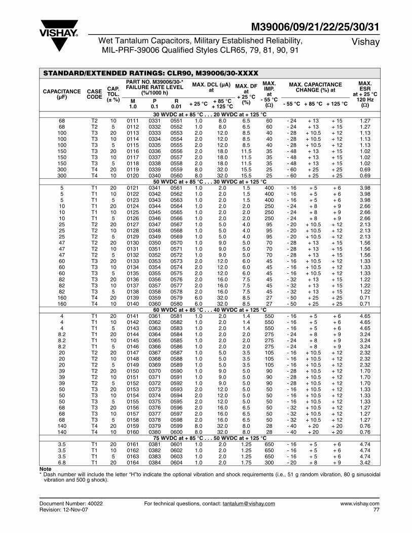
Document Number: 40022 For technical questions, contact: [email protected] www.vishay.comRevision: 12-Nov-07 77
M39006/09/21/22/25/30/31Wet Tantalum Capacitors, Military Established Reliability,MIL-PRF-39006 Qualified Styles CLR65, 79, 81, 90, 91
Vishay
STANDARD/EXTENDED RATINGS: CLR90, M39006/30-XXXX
CAPACITANCE (µF)
CASE CODE
CAP. TOL. (± %)
PART NO. M39006/30-*FAILURE RATE LEVEL
(%/1000 h)
MAX. DCL (µA)at
MAX. DFat
+ 25 °C(%)
MAX. IMP.at
- 55 °C()
MAX. CAPACITANCE CHANGE (%) at
MAX.ESR
at + 25 °C 120 Hz
()M
1.0P
0.1R
0.01 + 25 °C + 85 °C+ 125 °C - 55 °C + 85 °C + 125 °C
30 WVDC at + 85 °C . . . 20 WVDC at + 125 °C 68 T2 10 0111 0331 0551 1.0 8.0 6.5 60 - 24 + 13 + 15 1.27 68 T2 5 0112 0332 0552 1.0 8.0 6.5 60 - 24 + 13 + 15 1.27 100 T3 20 0113 0333 0553 2.0 12.0 8.5 40 - 28 + 10.5 + 12 1.13 100 T3 10 0114 0334 0554 2.0 12.0 8.5 40 - 28 + 10.5 + 12 1.13 100 T3 5 0115 0335 0555 2.0 12.0 8.5 40 - 28 + 10.5 + 12 1.13 150 T3 20 0116 0336 0556 2.0 18.0 11.5 35 - 48 + 13 + 15 1.02 150 T3 10 0117 0337 0557 2.0 18.0 11.5 35 - 48 + 13 + 15 1.02 150 T3 5 0118 0338 0558 2.0 18.0 11.5 35 - 48 + 13 + 15 1.02 300 T4 20 0119 0339 0559 8.0 32.0 15.5 25 - 60 + 25 + 25 0.69 300 T4 10 0120 0340 0560 8.0 32.0 15.5 25 - 60 + 25 + 25 0.69
50 WVDC at + 85 °C . . . 30 WVDC at + 125 °C 5 T1 20 0121 0341 0561 1.0 2.0 1.5 400 - 16 + 5 + 6 3.98 5 T1 10 0122 0342 0562 1.0 2.0 1.5 400 - 16 + 5 + 6 3.98 5 T1 5 0123 0343 0563 1.0 2.0 1.5 400 - 16 + 5 + 6 3.98 10 T1 20 0124 0344 0564 1.0 2.0 2.0 250 - 24 + 8 + 9 2.66 10 T1 10 0125 0345 0565 1.0 2.0 2.0 250 - 24 + 8 + 9 2.66 10 T1 5 0126 0346 0566 1.0 2.0 2.0 250 - 24 + 8 + 9 2.66 25 T2 20 0127 0347 0567 1.0 5.0 4.0 95 - 20 + 10.5 + 12 2.13 25 T2 10 0128 0348 0568 1.0 5.0 4.0 95 - 20 + 10.5 + 12 2.13 25 T2 5 0129 0349 0569 1.0 5.0 4.0 95 - 20 + 10.5 + 12 2.13 47 T2 20 0130 0350 0570 1.0 9.0 5.0 70 - 28 + 13 + 15 1.56 47 T2 10 0131 0351 0571 1.0 9.0 5.0 70 - 28 + 13 + 15 1.56 47 T2 5 0132 0352 0572 1.0 9.0 5.0 70 - 28 + 13 + 15 1.56 60 T3 20 0133 0353 0573 2.0 12.0 6.0 45 - 16 + 10.5 + 12 1.33 60 T3 10 0134 0354 0574 2.0 12.0 6.0 45 - 16 + 10.5 + 12 1.33 60 T3 5 0135 0355 0575 2.0 12.0 6.0 45 - 16 + 10.5 + 12 1.33 82 T3 20 0136 0356 0576 2.0 16.0 7.5 45 - 32 + 13 + 15 1.22 82 T3 10 0137 0357 0577 2.0 16.0 7.5 45 - 32 + 13 + 15 1.22 82 T3 5 0138 0358 0578 2.0 16.0 7.5 45 - 32 + 13 + 15 1.22 160 T4 20 0139 0359 0579 6.0 32.0 8.5 27 - 50 + 25 + 25 0.71 160 T4 10 0140 0360 0580 6.0 32.0 8.5 27 - 50 + 25 + 25 0.71
60 WVDC at + 85 °C . . . 40 WVDC at + 125 °C 4 T1 20 0141 0361 0581 1.0 2.0 1.4 550 - 16 + 5 + 6 4.65 4 T1 10 0142 0362 0582 1.0 2.0 1.4 550 - 16 + 5 + 6 4.65 4 T1 5 0143 0363 0583 1.0 2.0 1.4 550 - 16 + 5 + 6 4.65
8.2 T1 20 0144 0364 0584 1.0 2.0 2.0 275 - 24 + 8 + 9 3.24 8.2 T1 10 0145 0365 0585 1.0 2.0 2.0 275 - 24 + 8 + 9 3.24 8.2 T1 5 0146 0366 0586 1.0 2.0 2.0 275 - 24 + 8 + 9 3.24 20 T2 20 0147 0367 0587 1.0 5.0 3.5 105 - 16 + 10.5 + 12 2.32 20 T2 10 0148 0368 0588 1.0 5.0 3.5 105 - 16 + 10.5 + 12 2.32 20 T2 5 0149 0369 0589 1.0 5.0 3.5 105 - 16 + 10.5 + 12 2.32 39 T2 20 0150 0370 0590 1.0 9.0 5.0 90 - 28 + 10.5 + 12 1.70 39 T2 10 0151 0371 0591 1.0 9.0 5.0 90 - 28 + 10.5 + 12 1.70 39 T2 5 0152 0372 0592 1.0 9.0 5.0 90 - 28 + 10.5 + 12 1.70 50 T3 20 0153 0373 0593 2.0 12.0 5.0 50 - 16 + 10.5 + 12 1.33 50 T3 10 0154 0374 0594 2.0 12.0 5.0 50 - 16 + 10.5 + 12 1.33 50 T3 5 0155 0375 0595 2.0 12.0 5.0 50 - 16 + 10.5 + 12 1.33 68 T3 20 0156 0376 0596 2.0 16.0 6.5 50 - 32 + 10.5 + 12 1.27 68 T3 10 0157 0377 0597 2.0 16.0 6.5 50 - 32 + 10.5 + 12 1.27 68 T3 5 0158 0378 0598 2.0 16.0 6.5 50 - 32 + 10.5 + 12 1.27 140 T4 20 0159 0379 0599 8.0 32.0 8.0 28 - 40 + 20 + 20 0.76 140 T4 10 0160 0380 0600 8.0 32.0 8.0 28 - 40 + 20 + 20 0.76
75 WVDC at + 85 °C . . . 50 WVDC at + 125 °C 3.5 T1 20 0161 0381 0601 1.0 2.0 1.25 650 - 16 + 5 + 6 4.74 3.5 T1 10 0162 0382 0602 1.0 2.0 1.25 650 - 16 + 5 + 6 4.74 3.5 T1 5 0163 0383 0603 1.0 2.0 1.25 650 - 16 + 5 + 6 4.74 6.8 T1 20 0164 0384 0604 1.0 2.0 1.75 300 - 20 + 8 + 9 3.42
Note * Dash number will include the letter “H”to indicate the optional vibration and shock requirements (i.e., 51 g random vibration, 80 g sinusoidal
vibration and 500 g shock).
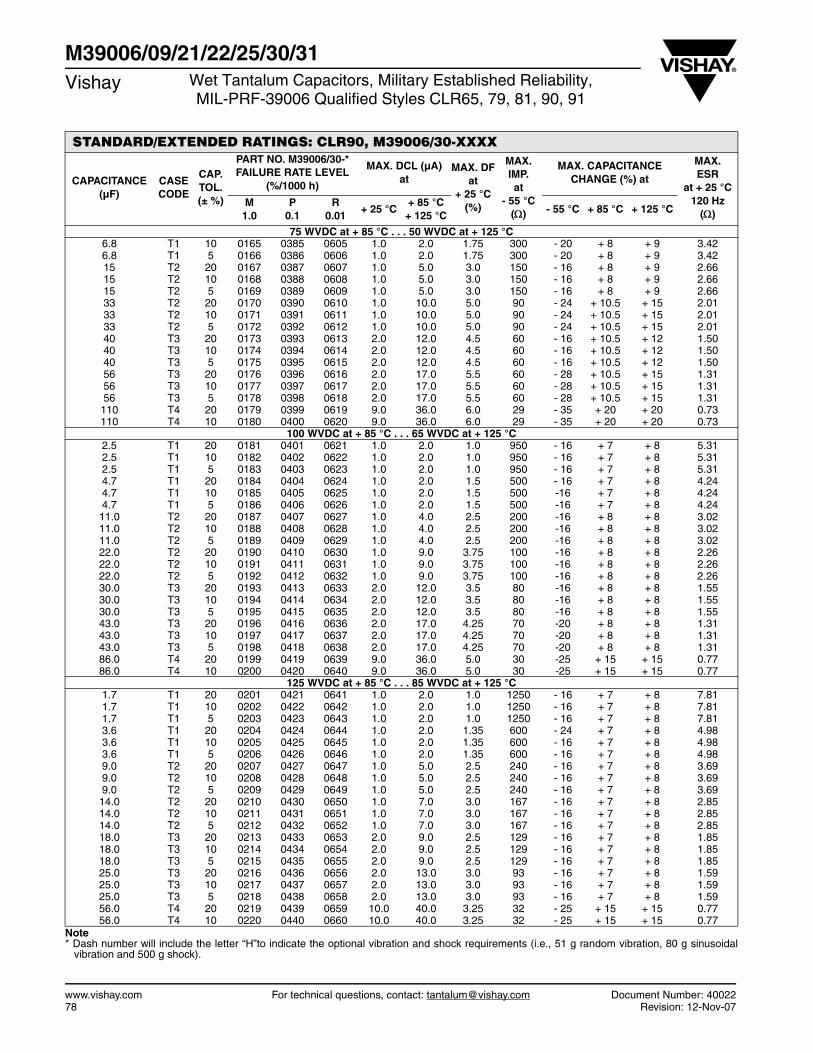
www.vishay.com For technical questions, contact: [email protected] Document Number: 4002278 Revision: 12-Nov-07
M39006/09/21/22/25/30/31Vishay Wet Tantalum Capacitors, Military Established Reliability,
MIL-PRF-39006 Qualified Styles CLR65, 79, 81, 90, 91
STANDARD/EXTENDED RATINGS: CLR90, M39006/30-XXXX
CAPACITANCE (µF)
CASE CODE
CAP. TOL. (± %)
PART NO. M39006/30-*FAILURE RATE LEVEL
(%/1000 h)
MAX. DCL (µA)at
MAX. DFat
+ 25 °C(%)
MAX. IMP.at
- 55 °C()
MAX. CAPACITANCE CHANGE (%) at
MAX.ESR
at + 25 °C 120 Hz
()M
1.0P
0.1R
0.01+ 25 °C
+ 85 °C+ 125 °C
- 55 °C + 85 °C + 125 °C
75 WVDC at + 85 °C . . . 50 WVDC at + 125 °C 6.8 T1 10 0165 0385 0605 1.0 2.0 1.75 300 - 20 + 8 + 9 3.42 6.8 T1 5 0166 0386 0606 1.0 2.0 1.75 300 - 20 + 8 + 9 3.42 15 T2 20 0167 0387 0607 1.0 5.0 3.0 150 - 16 + 8 + 9 2.66 15 T2 10 0168 0388 0608 1.0 5.0 3.0 150 - 16 + 8 + 9 2.66 15 T2 5 0169 0389 0609 1.0 5.0 3.0 150 - 16 + 8 + 9 2.66 33 T2 20 0170 0390 0610 1.0 10.0 5.0 90 - 24 + 10.5 + 15 2.01 33 T2 10 0171 0391 0611 1.0 10.0 5.0 90 - 24 + 10.5 + 15 2.01 33 T2 5 0172 0392 0612 1.0 10.0 5.0 90 - 24 + 10.5 + 15 2.01 40 T3 20 0173 0393 0613 2.0 12.0 4.5 60 - 16 + 10.5 + 12 1.50 40 T3 10 0174 0394 0614 2.0 12.0 4.5 60 - 16 + 10.5 + 12 1.50 40 T3 5 0175 0395 0615 2.0 12.0 4.5 60 - 16 + 10.5 + 12 1.50 56 T3 20 0176 0396 0616 2.0 17.0 5.5 60 - 28 + 10.5 + 15 1.31 56 T3 10 0177 0397 0617 2.0 17.0 5.5 60 - 28 + 10.5 + 15 1.31 56 T3 5 0178 0398 0618 2.0 17.0 5.5 60 - 28 + 10.5 + 15 1.31 110 T4 20 0179 0399 0619 9.0 36.0 6.0 29 - 35 + 20 + 20 0.73 110 T4 10 0180 0400 0620 9.0 36.0 6.0 29 - 35 + 20 + 20 0.73
100 WVDC at + 85 °C . . . 65 WVDC at + 125 °C 2.5 T1 20 0181 0401 0621 1.0 2.0 1.0 950 - 16 + 7 + 8 5.31 2.5 T1 10 0182 0402 0622 1.0 2.0 1.0 950 - 16 + 7 + 8 5.31 2.5 T1 5 0183 0403 0623 1.0 2.0 1.0 950 - 16 + 7 + 8 5.31 4.7 T1 20 0184 0404 0624 1.0 2.0 1.5 500 - 16 + 7 + 8 4.24 4.7 T1 10 0185 0405 0625 1.0 2.0 1.5 500 -16 + 7 + 8 4.24 4.7 T1 5 0186 0406 0626 1.0 2.0 1.5 500 -16 + 7 + 8 4.24 11.0 T2 20 0187 0407 0627 1.0 4.0 2.5 200 -16 + 8 + 8 3.02 11.0 T2 10 0188 0408 0628 1.0 4.0 2.5 200 -16 + 8 + 8 3.02 11.0 T2 5 0189 0409 0629 1.0 4.0 2.5 200 -16 + 8 + 8 3.02 22.0 T2 20 0190 0410 0630 1.0 9.0 3.75 100 -16 + 8 + 8 2.26 22.0 T2 10 0191 0411 0631 1.0 9.0 3.75 100 -16 + 8 + 8 2.26 22.0 T2 5 0192 0412 0632 1.0 9.0 3.75 100 -16 + 8 + 8 2.26 30.0 T3 20 0193 0413 0633 2.0 12.0 3.5 80 -16 + 8 + 8 1.55 30.0 T3 10 0194 0414 0634 2.0 12.0 3.5 80 -16 + 8 + 8 1.55 30.0 T3 5 0195 0415 0635 2.0 12.0 3.5 80 -16 + 8 + 8 1.55 43.0 T3 20 0196 0416 0636 2.0 17.0 4.25 70 -20 + 8 + 8 1.31 43.0 T3 10 0197 0417 0637 2.0 17.0 4.25 70 -20 + 8 + 8 1.31 43.0 T3 5 0198 0418 0638 2.0 17.0 4.25 70 -20 + 8 + 8 1.31 86.0 T4 20 0199 0419 0639 9.0 36.0 5.0 30 -25 + 15 + 15 0.77 86.0 T4 10 0200 0420 0640 9.0 36.0 5.0 30 -25 + 15 + 15 0.77
125 WVDC at + 85 °C . . . 85 WVDC at + 125 °C 1.7 T1 20 0201 0421 0641 1.0 2.0 1.0 1250 - 16 + 7 + 8 7.81 1.7 T1 10 0202 0422 0642 1.0 2.0 1.0 1250 - 16 + 7 + 8 7.81 1.7 T1 5 0203 0423 0643 1.0 2.0 1.0 1250 - 16 + 7 + 8 7.81 3.6 T1 20 0204 0424 0644 1.0 2.0 1.35 600 - 24 + 7 + 8 4.98 3.6 T1 10 0205 0425 0645 1.0 2.0 1.35 600 - 16 + 7 + 8 4.98 3.6 T1 5 0206 0426 0646 1.0 2.0 1.35 600 - 16 + 7 + 8 4.98 9.0 T2 20 0207 0427 0647 1.0 5.0 2.5 240 - 16 + 7 + 8 3.69 9.0 T2 10 0208 0428 0648 1.0 5.0 2.5 240 - 16 + 7 + 8 3.69 9.0 T2 5 0209 0429 0649 1.0 5.0 2.5 240 - 16 + 7 + 8 3.69 14.0 T2 20 0210 0430 0650 1.0 7.0 3.0 167 - 16 + 7 + 8 2.85 14.0 T2 10 0211 0431 0651 1.0 7.0 3.0 167 - 16 + 7 + 8 2.85 14.0 T2 5 0212 0432 0652 1.0 7.0 3.0 167 - 16 + 7 + 8 2.85 18.0 T3 20 0213 0433 0653 2.0 9.0 2.5 129 - 16 + 7 + 8 1.85 18.0 T3 10 0214 0434 0654 2.0 9.0 2.5 129 - 16 + 7 + 8 1.85 18.0 T3 5 0215 0435 0655 2.0 9.0 2.5 129 - 16 + 7 + 8 1.85 25.0 T3 20 0216 0436 0656 2.0 13.0 3.0 93 - 16 + 7 + 8 1.59 25.0 T3 10 0217 0437 0657 2.0 13.0 3.0 93 - 16 + 7 + 8 1.59 25.0 T3 5 0218 0438 0658 2.0 13.0 3.0 93 - 16 + 7 + 8 1.59 56.0 T4 20 0219 0439 0659 10.0 40.0 3.25 32 - 25 + 15 + 15 0.77 56.0 T4 10 0220 0440 0660 10.0 40.0 3.25 32 - 25 + 15 + 15 0.77
Note * Dash number will include the letter “H”to indicate the optional vibration and shock requirements (i.e., 51 g random vibration, 80 g sinusoidal
vibration and 500 g shock).

Document Number: 40022 For technical questions, contact: [email protected] www.vishay.comRevision: 12-Nov-07 79
M39006/09/21/22/25/30/31Wet Tantalum Capacitors, Military Established Reliability,MIL-PRF-39006 Qualified Styles CLR65, 79, 81, 90, 91
Vishay
STANDARD/EXTENDED RATINGS: CLR91, M39006/31-XXXX
CAPACITANCE (µF)
CASE CODE
CAP. TOL. (± %)
PART NO. M39006/31-*FAILURE RATE LEVEL
(%/1000 h)
MAX. DCL (µA)at
MAX. DFat
+ 25 °C(%)
MAX. IMP.at
- 55 °C()
MAX.. CAPACITANCE CHANGE (%) at
MAX.ESR
at + 25 °C 120 Hz
()M
1.0P
0.1R
0.01+ 25 °C
+ 85 °C+ 125 °C
- 55 °C + 85 °C + 125 °C
6 WVDC at + 85 °C . . .4 WVDC at + 125 °C 220 T1 20 0001 0089 0177 2 9 25 36 - 64 13 16 1.51220 T1 10 0002 0090 0178 2 9 25 36 - 64 13 16 1.51820 T2 20 0003 0091 0179 3 14 77.5 18 - 88 16 20 1.26820 T2 10 0004 0092 0180 3 14 77.5 18 - 88 16 20 1.261500 T3 20 0005 0093 0181 5 20 86 18 - 90 20 25 0.761500 T3 10 0006 0094 0182 5 20 86 18 - 90 20 25 0.762200 T4 20 0007 0095 0183 6 24 85 13 - 90 25 30 0.522200 T4 10 0008 0096 0184 6 24 85 13 - 90 25 30 0.52
8 WVDC at + 85 °C . . . 5 WVDC at + 125 °C 180 T1 20 0009 0097 0185 2 9 20.5 45 - 60 13 16 1.51180 T1 10 0010 0098 0186 2 9 20.5 45 - 60 13 16 1.51680 T2 20 0011 0099 0187 3 14 65 22 - 83 16 20 1.27680 T2 10 0012 0100 0188 3 14 65 22 - 83 16 20 1.271500 T3 20 0013 0101 0189 5 20 85 18 - 90 20 25 0.751500 T3 10 0014 0102 0190 5 20 85 18 - 90 20 25 0.751800 T4 20 0015 0103 0191 7 25 69 14 - 90 25 30 0.511800 T4 10 0016 0104 0192 7 25 69 14 - 90 25 30 0.51
10 WVDC at + 85 °C . . . 7 WVDC at + 125 °C 150 T1 20 0017 0105 0193 2 9 17 54 - 55 13 16 1.51150 T1 10 0018 0106 0194 2 9 17 54 - 55 13 16 1.51560 T2 20 0019 0107 0195 3 16 53 27 - 77 16 20 1.26560 T2 10 0020 0108 0196 3 16 53 27 - 77 16 20 1.261200 T3 20 0021 0109 0197 5 20 68.5 18 - 88 20 25 0.761200 T3 10 0022 0110 0198 5 20 68.5 18 - 88 20 25 0.761500 T4 20 0023 0111 0199 7 25 57 15 - 88 25 30 0.511500 T4 10 0024 0112 0200 7 25 57 15 - 88 25 30 0.51
15 WVDC at + 85 °C . . . 10 WVDC at + 125 °C 100 T1 20 0025 0113 0201 2 9 15 72 - 44 13 16 1.99100 T1 10 0026 0114 0202 2 9 15 72 - 44 13 16 1.99390 T2 20 0027 0115 0203 3 16 37 31 - 66 16 20 1.26390 T2 10 0028 0116 0204 3 16 37 31 - 66 16 20 1.26820 T3 20 0029 0117 0205 6 24 55.5 22 - 77 20 25 0.9820 T3 10 0030 0118 0206 6 24 55.5 22 - 77 20 25 0.91000 T4 20 0031 0119 0207 8 32 46 17 - 77 25 30 0.611000 T4 10 0032 0120 0208 8 32 46 17 - 77 25 30 0.61
25 WVDC at + 85 °C . . . 15 WVDC at + 125 °C 68 T1 20 0033 0121 0209 2 9 11 90 - 40 12 15 2.1568 T1 10 0034 0122 0210 2 9 11 90 - 40 12 15 2.15270 T2 20 0035 0123 0211 3 16 27.5 33 - 62 13 16 1.35270 T2 10 0036 0124 0212 3 16 27.5 33 - 62 13 16 1.35560 T3 20 0037 0125 0213 7 28 38 24 - 72 20 25 0.9560 T3 10 0038 0126 0214 7 28 38 24 - 72 20 25 0.9680 T4 20 0039 0127 0215 8 32 31.5 19 - 72 25 30 0.62680 T4 10 0040 0128 0216 8 32 31.5 19 - 72 25 30 0.62
30 WVDC at + 85 °C . . . 20 WVDC at + 125 °C 56 T1 20 0041 0129 0217 2 9 11 100 - 38 12 15 2.6156 T1 10 0042 0130 0218 2 9 11 100 - 38 12 15 2.61220 T2 20 0043 0131 0219 3 16 21 36 - 60 13 16 1.27220 T2 10 0044 0132 0220 3 16 21 36 - 60 13 16 1.27470 T3 20 0045 0133 0221 8 32 32 25 - 65 20 25 0.91470 T3 10 0046 0134 0222 8 32 32 25 - 65 20 25 0.91560 T4 20 0047 0135 0223 9 36 27.5 20 - 65 25 30 0.65560 T4 10 0048 0136 0224 9 36 27.5 20 - 65 25 30 0.65
Note * Dash number will include the letter “H”to indicate the optional vibration and shock requirements (i.e., 51 g random vibration, 80 g sinusoidal
vibration and 500 g shock).
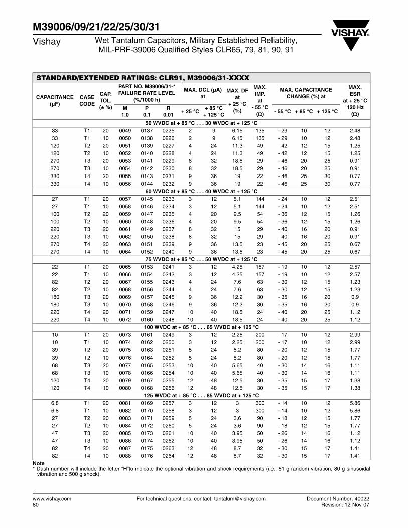
www.vishay.com For technical questions, contact: [email protected] Document Number: 4002280 Revision: 12-Nov-07
M39006/09/21/22/25/30/31Vishay Wet Tantalum Capacitors, Military Established Reliability,
MIL-PRF-39006 Qualified Styles CLR65, 79, 81, 90, 91
STANDARD/EXTENDED RATINGS: CLR91, M39006/31-XXXX
CAPACITANCE (µF)
CASE CODE
CAP. TOL. (± %)
PART NO. M39006/31-*FAILURE RATE LEVEL
(%/1000 h)
MAX. DCL (µA)at
MAX. DFat
+ 25 °C(%)
MAX. IMP.at
- 55 °C()
MAX. CAPACITANCE CHANGE (%) at
MAX.ESR
at + 25 °C 120 Hz
()M
1.0P
0.1R
0.01+ 25 °C
+ 85 °C+ 125 °C
- 55 °C + 85 °C + 125 °C
50 WVDC at + 85 °C . . . 30 WVDC at + 125 °C 33 T1 20 0049 0137 0225 2 9 6.15 135 - 29 10 12 2.4833 T1 10 0050 0138 0226 2 9 6.15 135 - 29 10 12 2.48120 T2 20 0051 0139 0227 4 24 11.3 49 - 42 12 15 1.25120 T2 10 0052 0140 0228 4 24 11.3 49 - 42 12 15 1.25270 T3 20 0053 0141 0229 8 32 18.5 29 - 46 20 25 0.91270 T3 10 0054 0142 0230 8 32 18.5 29 - 46 20 25 0.91330 T4 20 0055 0143 0231 9 36 19 22 - 46 25 30 0.77330 T4 10 0056 0144 0232 9 36 19 22 - 46 25 30 0.77
60 WVDC at + 85 °C . . . 40 WVDC at + 125 °C 27 T1 20 0057 0145 0233 3 12 5.1 144 - 24 10 12 2.5127 T1 10 0058 0146 0234 3 12 5.1 144 - 24 10 12 2.51100 T2 20 0059 0147 0235 4 20 9.5 54 - 36 12 15 1.26100 T2 10 0060 0148 0236 4 20 9.5 54 - 36 12 15 1.26220 T3 20 0061 0149 0237 8 32 15 29 - 40 16 20 0.91220 T3 10 0062 0150 0238 8 32 15 29 - 40 16 20 0.91270 T4 20 0063 0151 0239 9 36 13.5 23 - 45 20 25 0.67270 T4 10 0064 0152 0240 9 36 13.5 23 - 45 20 25 0.67
75 WVDC at + 85 °C . . . 50 WVDC at + 125 °C 22 T1 20 0065 0153 0241 3 12 4.25 157 - 19 10 12 2.5722 T1 10 0066 0154 0242 3 12 4.25 157 - 19 10 12 2.5782 T2 20 0067 0155 0243 4 24 7.6 63 - 30 12 15 1.2382 T2 10 0068 0156 0244 4 24 7.6 63 - 30 12 15 1.23180 T3 20 0069 0157 0245 9 36 12.2 30 - 35 16 20 0.9180 T3 10 0070 0158 0246 9 36 12.2 30 - 35 16 20 0.9220 T4 20 0071 0159 0247 10 40 18.5 24 - 40 20 25 1.12220 T4 10 0072 0160 0248 10 40 18.5 24 - 40 20 25 1.12
100 WVDC at + 85 °C . . . 65 WVDC at + 125 °C 10 T1 20 0073 0161 0249 3 12 2.25 200 - 17 10 12 2.9910 T1 10 0074 0162 0250 3 12 2.25 200 - 17 10 12 2.9939 T2 20 0075 0163 0251 5 24 5.2 80 - 20 12 15 1.7739 T2 10 0076 0164 0252 5 24 5.2 80 - 20 12 15 1.7768 T3 20 0077 0165 0253 10 40 5.65 40 - 30 14 16 1.1168 T3 10 0078 0166 0254 10 40 5.65 40 - 30 14 16 1.11120 T4 20 0079 0167 0255 12 48 12.5 30 - 35 15 17 1.38120 T4 10 0080 0168 0256 12 48 12.5 30 - 35 15 17 1.38
125 WVDC at + 85 °C . . . 85 WVDC at + 125 °C 6.8 T1 20 0081 0169 0257 3 12 3 300 - 14 10 12 5.866.8 T1 10 0082 0170 0258 3 12 3 300 - 14 10 12 5.8627 T2 20 0083 0171 0259 5 24 3.6 90 - 18 12 15 1.7727 T2 10 0084 0172 0260 5 24 3.6 90 - 18 12 15 1.7747 T3 20 0085 0173 0261 10 40 3.95 50 - 26 14 16 1.1247 T3 10 0086 0174 0262 10 40 3.95 50 - 26 14 16 1.1282 T4 20 0087 0175 0263 12 48 8.7 32 - 30 15 17 1.4182 T4 10 0088 0176 0264 12 48 8.7 32 - 30 15 17 1.41
Note * Dash number will include the letter “H”to indicate the optional vibration and shock requirements (i.e., 51 g random vibration, 80 g sinusoidal
vibration and 500 g shock).

136Dwww.vishay.com Vishay
Revision: 22-Dec-10 81 Document Number: 40132
For technical questions, contact: [email protected] DOCUMENT IS SUBJECT TO CHANGE WITHOUT NOTICE. THE PRODUCTS DESCRIBED HEREIN AND THIS DOCUMENT
ARE SUBJECT TO SPECIFIC DISCLAIMERS, SET FORTH AT www.vishay.com/doc?91000
Wet Tantalum Capacitors Tantalum-Case with Glass-to-TantalumHermetic Seal for - 55 °C to + 125 °C Operation, Low ESR
FEATURES• Military specification MIL-PRF-39006/30 and
39006/31. Model 136D capacitors arecommercial equivalents of Military styleCLR90 and CLR91.
• Capacitors to meet the MIL-specs must beordered by M39006 part numbers shown in the relativespecification.
• Terminations: standard tin/lead (SnPb), 100 % tin(RoHS compliant) available
• Standard and extended ratings
• Low ESR
• Compliant to RoHS Directive 2002/95/EC
Note* Pb containing terminations are not RoHS compliant, exemptions
may apply
PERFORMANCE CHARACTERISTICSOperating Temperature: - 55 °C to + 85 °C(To + 125 °C with voltage derating)
Capacitance Tolerance: At 120 Hz, + 25 °C. ± 20 %standard. ± 10 %, ± 5 % available as special.
DC Leakage Current (DCL Max.): At + 25 °C and above:Leakage current shall not exceed the values listed in theStandard Ratings Tables.
Life Test: Capacitors are capable of withstanding a 2000 hlife test at a temperature of + 85 °C or + 125 °C at theapplicable rated DC working voltage.
Following life test:
1. DCL, measured at + 85 °C rated voltage, shall not be inexcess of the original requirement.
2. The equivalent series resistance shall not exceed 150 %of the initial requirement.
3. Change in capacitance shall not exceed 10 % from theinitial measurement.
Note• Packaging: The use of formed plastic trays for packaging these axial lead components is standard. Tape and reel is not recommended due
to the unit weight.
ORDERING INFORMATION136D 306 X0 006 C 2 E3
MODEL CAPACITANCE CAPACITANCETOLERANCE
DC VOLTAGE RATING AT + 85 °C
CASE CODE STYLE NUMBER RoHSCOMPLIANT
This is expressedin picofarads. The
first two digitsare the significantfigures. The thirdis the number ofzeros to follow
X0 = ± 20 %X9 = ± 10 %X5 = ± 5 %
This is expressed involts. To complete thethree-digit block, zeros
precede the voltagerating. A decimal pointis indicated by an “R”
(6R3 = 6.3 V)
See Ratings and Case
Codes table
Std. temperature(max. + 125 °C)
0 = No insulatingsleeve
2 = Polyesterinsulation sleeve
3 = High temperaturefilm insulation
E3 = 100 % tintermination
(RoHS compliantdesign)
Blank = SnPbtermination(standarddesign)
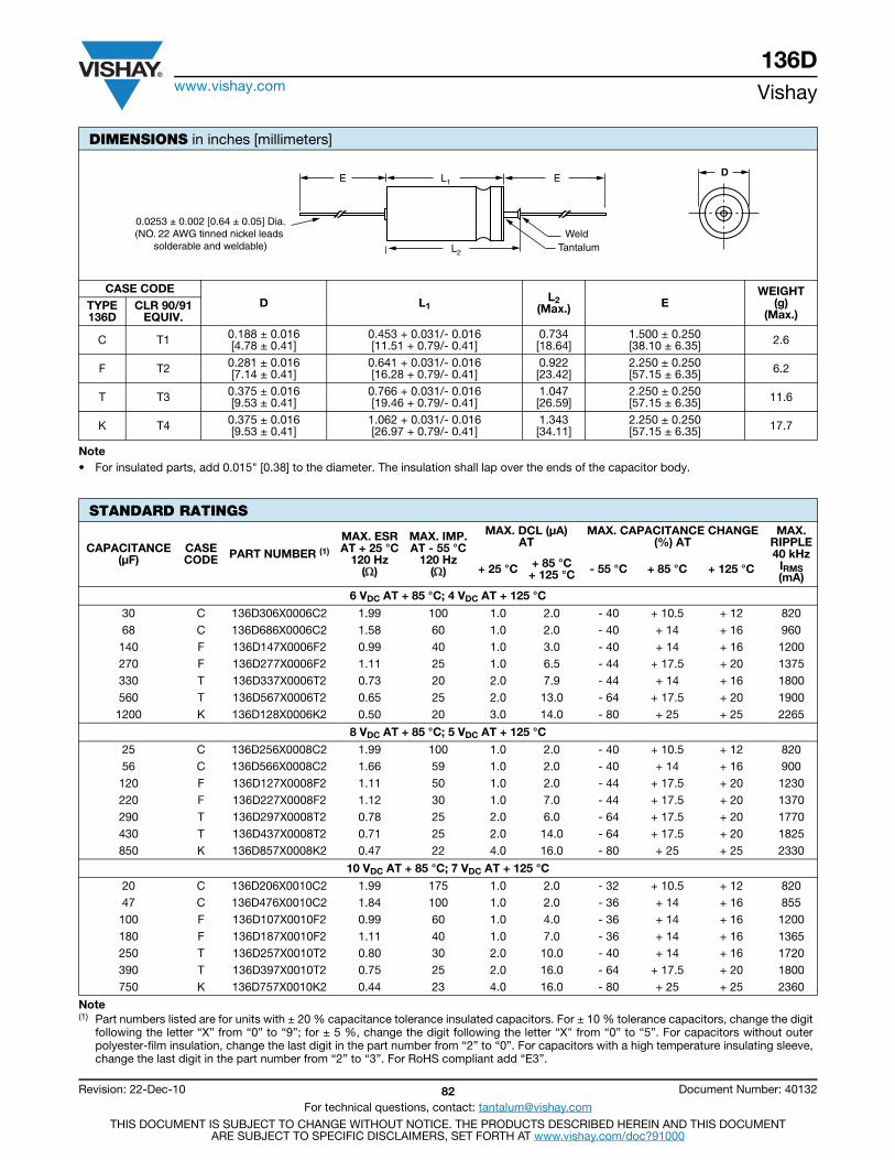
136Dwww.vishay.com Vishay
Revision: 22-Dec-10 82 Document Number: 40132
For technical questions, contact: [email protected] DOCUMENT IS SUBJECT TO CHANGE WITHOUT NOTICE. THE PRODUCTS DESCRIBED HEREIN AND THIS DOCUMENT
ARE SUBJECT TO SPECIFIC DISCLAIMERS, SET FORTH AT www.vishay.com/doc?91000
Note• For insulated parts, add 0.015" [0.38] to the diameter. The insulation shall lap over the ends of the capacitor body.
DIMENSIONS in inches [millimeters]
CASE CODE D L1
L2 (Max.) E
WEIGHT (g)
(Max.) TYPE 136D
CLR 90/91 EQUIV.
C T1 0.188 ± 0.016 [4.78 ± 0.41]
0.453 + 0.031/- 0.016 [11.51 + 0.79/- 0.41]
0.734 [18.64]
1.500 ± 0.250 [38.10 ± 6.35] 2.6
F T2 0.281 ± 0.016 [7.14 ± 0.41]
0.641 + 0.031/- 0.016 [16.28 + 0.79/- 0.41]
0.922 [23.42]
2.250 ± 0.250 [57.15 ± 6.35] 6.2
T T3 0.375 ± 0.016 [9.53 ± 0.41]
0.766 + 0.031/- 0.016 [19.46 + 0.79/- 0.41]
1.047 [26.59]
2.250 ± 0.250[57.15 ± 6.35] 11.6
K T4 0.375 ± 0.016 [9.53 ± 0.41]
1.062 + 0.031/- 0.016 [26.97 + 0.79/- 0.41]
1.343 [34.11]
2.250 ± 0.250[57.15 ± 6.35] 17.7
STANDARD RATINGS
CAPACITANCE (μF)
CASECODE PART NUMBER (1)
MAX. ESRAT + 25 °C
120 Hz()
MAX. IMP.AT - 55 °C
120 Hz()
MAX. DCL (μA)AT
MAX. CAPACITANCE CHANGE(%) AT
MAX.RIPPLE40 kHz
IRMS (mA)
+ 25 °C + 85 °C+ 125 °C - 55 °C + 85 °C + 125 °C
6 VDC AT + 85 °C; 4 VDC AT + 125 °C
30 C 136D306X0006C2 1.99 100 1.0 2.0 - 40 + 10.5 + 12 820 68 C 136D686X0006C2 1.58 60 1.0 2.0 - 40 + 14 + 16 960 140 F 136D147X0006F2 0.99 40 1.0 3.0 - 40 + 14 + 16 1200 270 F 136D277X0006F2 1.11 25 1.0 6.5 - 44 + 17.5 + 20 1375 330 T 136D337X0006T2 0.73 20 2.0 7.9 - 44 + 14 + 16 1800 560 T 136D567X0006T2 0.65 25 2.0 13.0 - 64 + 17.5 + 20 1900 1200 K 136D128X0006K2 0.50 20 3.0 14.0 - 80 + 25 + 25 2265
8 VDC AT + 85 °C; 5 VDC AT + 125 °C
25 C 136D256X0008C2 1.99 100 1.0 2.0 - 40 + 10.5 + 12 820 56 C 136D566X0008C2 1.66 59 1.0 2.0 - 40 + 14 + 16 900 120 F 136D127X0008F2 1.11 50 1.0 2.0 - 44 + 17.5 + 20 1230 220 F 136D227X0008F2 1.12 30 1.0 7.0 - 44 + 17.5 + 20 1370 290 T 136D297X0008T2 0.78 25 2.0 6.0 - 64 + 17.5 + 20 1770 430 T 136D437X0008T2 0.71 25 2.0 14.0 - 64 + 17.5 + 20 1825 850 K 136D857X0008K2 0.47 22 4.0 16.0 - 80 + 25 + 25 2330
10 VDC AT + 85 °C; 7 VDC AT + 125 °C
20 C 136D206X0010C2 1.99 175 1.0 2.0 - 32 + 10.5 + 12 820 47 C 136D476X0010C2 1.84 100 1.0 2.0 - 36 + 14 + 16 855 100 F 136D107X0010F2 0.99 60 1.0 4.0 - 36 + 14 + 16 1200 180 F 136D187X0010F2 1.11 40 1.0 7.0 - 36 + 14 + 16 1365 250 T 136D257X0010T2 0.80 30 2.0 10.0 - 40 + 14 + 16 1720 390 T 136D397X0010T2 0.75 25 2.0 16.0 - 64 + 17.5 + 20 1800 750 K 136D757X0010K2 0.44 23 4.0 16.0 - 80 + 25 + 25 2360
Note(1) Part numbers listed are for units with ± 20 % capacitance tolerance insulated capacitors. For ± 10 % tolerance capacitors, change the digit
following the letter “X” from “0” to “9”; for ± 5 %, change the digit following the letter “X" from “0” to “5”. For capacitors without outerpolyester-film insulation, change the last digit in the part number from “2” to “0”. For capacitors with a high temperature insulating sleeve,change the last digit in the part number from “2” to “3”. For RoHS compliant add “E3”.
L2
WeldTantalum
0.0253 ± 0.002 [0.64 ± 0.05] Dia.(NO. 22 AWG tinned nickel leads
solderable and weldable)
DE L1 E
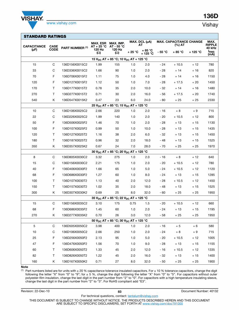
136Dwww.vishay.com Vishay
Revision: 22-Dec-10 83 Document Number: 40132
For technical questions, contact: [email protected] DOCUMENT IS SUBJECT TO CHANGE WITHOUT NOTICE. THE PRODUCTS DESCRIBED HEREIN AND THIS DOCUMENT
ARE SUBJECT TO SPECIFIC DISCLAIMERS, SET FORTH AT www.vishay.com/doc?91000
15 VDC AT + 85 °C; 10 VDC AT + 125 °C
15 C 136D156X0015C2 1.99 155 1.0 2.0 - 24 + 10.5 + 12 780
33 C 136D336X0015C2 1.66 90 1.0 2.0 - 28 + 14 + 16 820
70 F 136D706X0015F2 1.11 75 1.0 4.0 - 28 + 14 + 16 1150
120 F 136D127X0015F2 1.12 50 1.0 7.0 - 28 + 17.5 + 20 1450
170 T 136D177X0015T2 0.78 35 2.0 10.0 - 32 + 14 + 16 1480
270 T 136D277X0015T2 0.71 30 2.0 16.0 - 56 + 17.5 + 20 1740
540 K 136D547X0015K2 0.47 23 6.0 24.0 - 80 + 25 + 25 2330
25 VDC AT + 85 °C; 15 VDC AT + 125 °C
10 C 136D106X0025C2 2.66 220 1.0 2.0 - 16 + 8 + 9 715
22 C 136D226X0025C2 1.99 140 1.0 2.0 - 20 + 10.5 + 12 800
50 F 136D506X0025F2 1.46 70 1.0 2.0 - 28 + 13 + 15 1130
100 F 136D107X0025F2 0.99 50 1.0 10.0 - 28 + 13 + 15 1435
120 T 136D127X0025T2 1.16 38 2.0 6.0 - 32 + 13 + 15 1450
180 T 136D187X0025T2 0.96 32 2.0 18.0 - 48 + 13 + 15 1525
350 K 136D357X0025K2 0.67 24 7.0 28.0 - 70 + 25 + 25 1970
30 VDC AT + 85 °C; 20 VDC AT + 125 °C
8 C 136D805X0030C2 3.32 275 1.0 2.0 - 16 + 8 + 12 640
15 C 136D156X0030C2 2.21 175 1.0 2.0 - 20 + 10.5 + 12 780
40 F 136D406X0030F2 1.66 65 1.0 5.0 - 24 + 10.5 + 12 1120
68 F 136D686X0030F2 1.27 60 1.0 8.0 - 24 + 13 + 15 1285
100 T 136D107X0030T2 1.13 40 2.0 12.0 - 28 + 10.5 + 12 1450
150 T 136D157X0030T2 1.02 35 2.0 18.0 - 48 + 13 + 15 1525
300 K 136D307X0030K2 0.69 25 8.0 32.0 - 60 + 25 + 25 1950
35 VDC AT + 85 °C; 22 VDC AT + 125 °C
15 C 136D156X0035C2 3.10 175 0.75 1.5 - 20 + 10.5 + 12 660
68 F 136D686X0035F2 1.45 60 1.0 2.0 - 24 + 13 + 15 1195
270 K 136D277X0035K2 0.70 26 3.0 12.0 - 58 + 25 + 25 1950
50 VDC AT + 85 °C; 30 VDC AT + 125 °C
5 C 136D505X0050C2 3.98 400 1.0 2.0 - 16 + 5 + 6 580
10 C 136D106X0050C2 2.66 250 1.0 2.0 - 24 + 8 + 9 715
25 F 136D256X0050F2 2.13 95 1.0 5.0 - 20 + 10.5 + 12 1005
47 F 136D476X0050F2 1.56 70 1.0 9.0 - 28 + 13 + 15 1155
60 T 136D606X0050T2 1.33 45 2.0 12.0 - 16 + 10.5 + 12 1335
82 T 136D826X0050T2 1.22 45 2.0 16.0 - 32 + 13 + 15 1400
160 K 136D167X0050K2 0.71 27 8.0 32.0 - 50 + 25 + 25 1900
STANDARD RATINGS
CAPACITANCE (μF)
CASECODE PART NUMBER (1)
MAX. ESRAT + 25 °C
120 Hz()
MAX. IMP.AT - 55 °C
120 Hz()
MAX. DCL (μA)AT
MAX. CAPACITANCE CHANGE(%) AT
MAX.RIPPLE40 kHz
IRMS (mA)
+ 25 °C + 85 °C+ 125 °C - 55 °C + 85 °C + 125 °C
Note(1) Part numbers listed are for units with ± 20 % capacitance tolerance insulated capacitors. For ± 10 % tolerance capacitors, change the digit
following the letter “X” from “0” to “9”; for ± 5 %, change the digit following the letter “X" from “0” to “5”. For capacitors without outerpolyester-film insulation, change the last digit in the part number from “2” to “0”. For capacitors with a high temperature insulating sleeve,change the last digit in the part number from “2” to “3”. For RoHS compliant add “E3”.

136Dwww.vishay.com Vishay
Revision: 22-Dec-10 84 Document Number: 40132
For technical questions, contact: [email protected] DOCUMENT IS SUBJECT TO CHANGE WITHOUT NOTICE. THE PRODUCTS DESCRIBED HEREIN AND THIS DOCUMENT
ARE SUBJECT TO SPECIFIC DISCLAIMERS, SET FORTH AT www.vishay.com/doc?91000
60 VDC AT + 85 °C; 40 VDC AT + 125 °C
4 C 136D405X0060C2 4.65 550 1.0 2.0 - 16 + 5 + 6 525
8.2 C 136D825X0060C2 3.24 275 1.0 2.0 - 24 + 8 + 9 625
20 F 136D206X0060F2 2.32 105 1.0 5.0 - 16 + 8 + 12 930
39 F 136D396X0060F2 1.70 90 1.0 9.0 - 28 + 10.5 + 12 1110
50 T 136D506X0060T2 1.33 50 2.0 12.0 - 16 + 10.5 + 12 1330
68 T 136D686X0060T2 1.27 50 2.0 16.0 - 32 + 10.5 + 15 1365
140 K 136D147X0060K2 0.76 28 8.0 32.0 - 40 + 20 + 20 1850
75 VDC AT + 85 °C; 50 VDC AT + 125 °C
3.5 C 136D355X0075C2 4.74 650 1.0 2.0 - 16 + 5 + 6 525
6.8 C 136D685X0075C2 3.42 300 1.0 2.0 - 20 + 8 + 9 610
15 F 136D156X0075F2 2.66 150 1.0 5.0 - 16 + 10.5 + 9 890
33 F 136D336X0075F2 2.01 90 1.0 10.0 - 24 + 10.5 + 15 1000
40 T 136D406X0075T2 1.50 60 2.0 12.0 - 16 + 10.5 + 12 1250
56 T 136D566X0075T2 1.31 60 2.0 17.0 - 28 + 10.5 + 15 1335
110 K 136D117X0075K2 0.73 29 9.0 36 .0 - 35 + 20 + 20 1850
100 VDC AT + 85 °C; 65 VDC AT + 125 °C
2.5 C 136D255X0100C2 5.31 950 1.0 4.0 - 16 + 8 + 8 505
4.7 C 136D475X0100C2 4.24 500 1.0 2.0 - 16 + 7 + 8 565
11 F 136D116X0100F2 3.02 200 1.0 4.0 - 16 + 7 + 8 835
22 F 136D226X0100F2 2.26 100 1.0 9.0 - 16 + 7 + 8 965
25 T 136D256X0100T2 1.60 93 2.0 13.0 - 16 + 7 + 8 1200
30 T 136D306X0100T2 1.55 80 2.0 12.0 - 16 + 8 + 8 1240
43 T 136D436X0100T2 1.31 70 2.0 17.0 - 20 + 8 + 8 1335
56 K 136D566X0100K2 0.80 32 10.0 40.0 - 25 + 15 + 15 1800
86 K 136D866X0100K2 0.77 30 9.0 36.0 - 25 + 15 + 15 1800
125 VDC AT + 85 °C; 85 VDC AT + 125 °C
1.7 C 136D175X0125C2 7.81 1250 1.0 2.0 - 16 + 7 + 8 415
3.6 C 136D365X0125C2 4.98 600 1.0 2.0 - 16 + 7 + 8 520
9 F 136D905X0125F2 3.69 240 1.0 5.0 - 16 + 7 + 8 755
14 F 136D146X0125F2 2.85 167 1.0 7.0 - 16 + 7 + 8 860
18 T 136D186X0125T2 1.85 129 2.0 9.0 - 16 + 7 + 8 1130
25 T 136D256X0125T2 1.59 93 2 13 - 16 + 7 + 8 1200
56 K 136D566X0125K2 0.77 32 10 40 - 25 + 15 + 15 1800
STANDARD RATINGS
CAPACITANCE (μF)
CASECODE PART NUMBER (1)
MAX. ESRAT + 25 °C
120 Hz()
MAX. IMP.AT - 55 °C
120 Hz()
MAX. DCL (μA)AT
MAX. CAPACITANCE CHANGE(%) AT
MAX.RIPPLE40 kHz
IRMS (mA)
+ 25 °C + 85 °C+ 125 °C - 55 °C + 85 °C + 125 °C
Note(1) Part numbers listed are for units with ± 20 % capacitance tolerance insulated capacitors. For ± 10 % tolerance capacitors, change the digit
following the letter “X” from “0” to “9”; for ± 5 %, change the digit following the letter “X" from “0” to “5”. For capacitors without outerpolyester-film insulation, change the last digit in the part number from “2” to “0”. For capacitors with a high temperature insulating sleeve,change the last digit in the part number from “2” to “3”. For RoHS compliant add “E3”.

136Dwww.vishay.com Vishay
Revision: 22-Dec-10 85 Document Number: 40132
For technical questions, contact: [email protected] DOCUMENT IS SUBJECT TO CHANGE WITHOUT NOTICE. THE PRODUCTS DESCRIBED HEREIN AND THIS DOCUMENT
ARE SUBJECT TO SPECIFIC DISCLAIMERS, SET FORTH AT www.vishay.com/doc?91000
EXTENDED RATINGS
CAPACITANCE (μF)
CASE CODE PART NUMBER (1)
MAX. ESRAT + 25 °C
120 Hz()
MAX. IMP.AT - 55 °C
120 Hz()
MAX. DCL (μA)AT
MAX. CAPACITANCE CHANGE (%) AT
MAX. RIPPLE 40 kHz
IRMS (mA)
+ 25 °C + 85 °C+ 125 °C - 55 °C + 85 °C + 125 °C
6 VDC AT + 85 °C; 4 VDC AT + 125 °C
220 C 136D227X0006C2 1.50 36 2 9 - 64 + 13 + 16 1000
560 F 136D567X0006F2 1.25 21 3 9 - 77 + 16 + 20 1500
820 F 136D827X0006F2 1.25 18 3 14 - 88 + 16 + 20 1500
1200 T 136D128X0006T2 0.75 18 5 18 - 88 + 20 + 25 1900
1500 T 136D158X0006T2 0.75 18 5 20 - 90 + 20 + 25 1900
2200 K 136D228X0006K2 0.50 13 6 24 - 90 + 25 + 30 2300
8 VDC AT + 85 °C; 5 VDC AT + 125 °C
180 C 136D187X0008C2 1.50 45 2 9 - 60 + 13 + 16 1000
680 F 136D687X0008F2 1.25 22 3 14 - 83 + 16 + 20 1500
1500 T 136D158X0008T2 0.75 18 5 20 - 90 + 20 + 25 1900
1800 K 136D188X0008K2 0.50 14 7 25 - 90 + 25 + 30 2300
10 VDC AT + 85 °C; 7 VDC AT + 125 °C
120 C 136D127X0010C2 1.60 54 2 6 - 40 + 14 + 16 900
150 C 136D157X0010C2 1.50 54 2 9 - 55 + 13 + 16 900
390 F 136D397X0010F2 1.25 27 3 9 - 66 + 16 + 20 1450
560 F 136D567X0010F2 1.25 27 3 16 - 77 + 16 + 20 1450
1200 T 136D128X0010T2 0.75 18 5 20 - 88 + 20 + 25 1850
1500 K 136D158X0010K2 0.50 15 7 25 - 88 + 25 + 30 2300
15 VDC AT + 85 °C; 10 VDC AT + 125 °C
82 C 136D826X0015C2 0.95 72 2 6 - 35 + 12 + 16 900
100 C 136D107X0015C2 0.95 72 2 9 - 44 + 13 + 16 900
270 F 136D277X0015F2 1.25 31 3 9 - 62 + 16 + 15 1450
390 F 136D397X0015F2 1.25 31 3 16 - 66 + 16 + 20 1450
680 T 136D687X0015T2 0.90 22 6 18 - 74 + 20 + 25 1800
820 T 136D827X0015T2 0.90 22 6 24 - 77 + 20 + 25 1800
1000 K 136D108X0015K2 0.60 17 8 32 - 77 + 25 + 30 2330
25 VDC AT + 85 °C; 15 VDC AT + 125 °C
47 C 136D476X0025C2 2.60 100 2 6 - 23 + 12 + 15 800
56 C 136D566X0025C2 2.15 90 2 6 - 25 + 12 + 15 850
68 C 136D686X0025C2 2.15 90 2 9 - 40 + 12 + 15 850
180 F 136D187X0025F2 1.35 33 3 9 - 54 + 13 + 15 1400
270 F 136D277X0025F2 1.35 33 3 16 - 62 + 13 + 16 1400
470 T 136D477X0025T2 0.90 24 6 18 - 65 + 18 + 25 1750
560 T 136D567X0025T2 0.90 24 7 28 - 72 + 20 + 25 1750
680 K 136D687X0025K2 0.60 19 8 32 - 72 + 25 + 30 2100
30 VDC AT + 85 °C; 20 VDC AT + 125 °C
47 C 136D476X0030C2 2.60 100 2 6 - 23 + 12 + 15 800
56 C 136D566X0030C2 2.60 100 2 9 - 38 + 12 + 15 800
150 F 136D157X0030F2 1.25 36 3 9 - 42 + 13 + 15 1200
220 F 136D227X0030F2 1.25 36 3 16 - 60 + 13 + 16 1200
390 T 136D397X0030T2 0.90 25 6 18 - 55 + 18 + 25 1500
470 T 136D477X0030T2 0.90 25 8 32 - 65 + 20 + 25 1500
560 K 136D567X0030K2 0.65 20 9 36 - 65 + 25 + 30 2000
Note(1) Part numbers listed are for units with ± 20 % capacitance tolerance insulated capacitors. For ± 10 % tolerance capacitors, change the digit
following the letter “X” from “0” to “9”; for ± 5 %, change the digit following the letter “X" from “0” to “5”. For capacitors without outerpolyester-film insulation, change the last digit in the part number from “2” to “0”. For capacitors with a high temperature insulating sleeve,change the last digit in the part number from “2” to “3”. For RoHS compliant add “E3”.
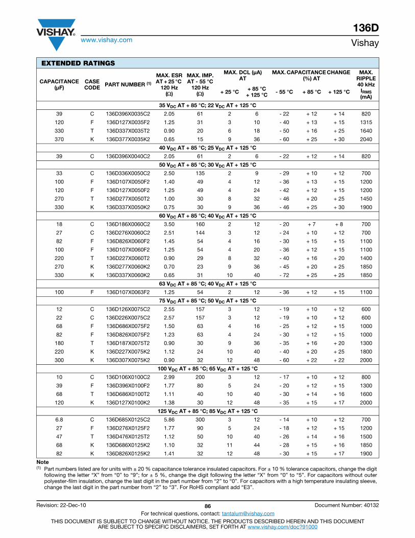
136Dwww.vishay.com Vishay
Revision: 22-Dec-10 86 Document Number: 40132
For technical questions, contact: [email protected] DOCUMENT IS SUBJECT TO CHANGE WITHOUT NOTICE. THE PRODUCTS DESCRIBED HEREIN AND THIS DOCUMENT
ARE SUBJECT TO SPECIFIC DISCLAIMERS, SET FORTH AT www.vishay.com/doc?91000
35 VDC AT + 85 °C; 22 VDC AT + 125 °C
39 C 136D396X0035C2 2.05 61 2 6 - 22 + 12 + 14 820
120 F 136D127X0035F2 1.25 31 3 10 - 40 + 13 + 15 1315
330 T 136D337X0035T2 0.90 20 6 18 - 50 + 16 + 25 1640
370 K 136D377X0035K2 0.65 15 9 36 - 60 + 25 + 30 2040
40 VDC AT + 85 °C; 25 VDC AT + 125 °C
39 C 136D396X0040C2 2.05 61 2 6 - 22 + 12 + 14 820
50 VDC AT + 85 °C; 30 VDC AT + 125 °C
33 C 136D336X0050C2 2.50 135 2 9 - 29 + 10 + 12 700
100 F 136D107X0050F2 1.40 49 4 12 - 36 + 13 + 15 1200
120 F 136D127X0050F2 1.25 49 4 24 - 42 + 12 + 15 1200
270 T 136D277X0050T2 1.00 30 8 32 - 46 + 20 + 25 1450
330 K 136D337X0050K2 0.75 30 9 36 - 46 + 25 + 30 1900
60 VDC AT + 85 °C; 40 VDC AT + 125 °C
18 C 136D186X0060C2 3.50 160 2 12 - 20 + 7 + 8 700
27 C 136D276X0060C2 2.51 144 3 12 - 24 + 10 + 12 700
82 F 136D826X0060F2 1.45 54 4 16 - 30 + 15 + 15 1100
100 F 136D107X0060F2 1.25 54 4 20 - 36 + 12 + 15 1100
220 T 136D227X0060T2 0.90 29 8 32 - 40 + 16 + 20 1400
270 K 136D277X0060K2 0.70 23 9 36 - 45 + 20 + 25 1850
330 K 136D337X0060K2 0.65 31 10 40 - 72 + 25 + 25 1850
63 VDC AT + 85 °C; 40 VDC AT + 125 °C
100 F 136D107X0063F2 1.25 54 2 12 - 36 + 12 + 15 1100
75 VDC AT + 85 °C; 50 VDC AT + 125 °C
12 C 136D126X0075C2 2.55 157 3 12 - 19 + 10 + 12 600
22 C 136D226X0075C2 2.57 157 3 12 - 19 + 10 + 12 600
68 F 136D686X0075F2 1.50 63 4 16 - 25 + 12 + 15 1000
82 F 136D826X0075F2 1.23 63 4 24 - 30 + 12 + 15 1000
180 T 136D187X0075T2 0.90 30 9 36 - 35 + 16 + 20 1300
220 K 136D227X0075K2 1.12 24 10 40 - 40 + 20 + 25 1800
300 K 136D307X0075K2 0.90 32 12 48 - 60 + 22 + 22 2000
100 VDC AT + 85 °C; 65 VDC AT + 125 °C
10 C 136D106X0100C2 2.99 200 3 12 - 17 + 10 + 12 800
39 F 136D396X0100F2 1.77 80 5 24 - 20 + 12 + 15 1300
68 T 136D686X0100T2 1.11 40 10 40 - 30 + 14 + 16 1600
120 K 136D127X0100K2 1.38 30 12 48 - 35 + 15 + 17 2000
125 VDC AT + 85 °C; 85 VDC AT + 125 °C
6.8 C 136D685X0125C2 5.86 300 3 12 - 14 + 10 + 12 700
27 F 136D276X0125F2 1.77 90 5 24 - 18 + 12 + 15 1200
47 T 136D476X0125T2 1.12 50 10 40 - 26 + 14 + 16 1500
68 K 136D686X0125K2 1.10 32 11 44 - 28 + 15 + 16 1850
82 K 136D826X0125K2 1.41 32 12 48 - 30 + 15 + 17 1900
EXTENDED RATINGS
CAPACITANCE (μF)
CASE CODE PART NUMBER (1)
MAX. ESRAT + 25 °C
120 Hz()
MAX. IMP.AT - 55 °C
120 Hz()
MAX. DCL (μA)AT
MAX. CAPACITANCE CHANGE (%) AT
MAX. RIPPLE 40 kHz
IRMS (mA)
+ 25 °C + 85 °C+ 125 °C - 55 °C + 85 °C + 125 °C
Note(1) Part numbers listed are for units with ± 20 % capacitance tolerance insulated capacitors. For ± 10 % tolerance capacitors, change the digit
following the letter “X” from “0” to “9”; for ± 5 %, change the digit following the letter “X" from “0” to “5”. For capacitors without outerpolyester-film insulation, change the last digit in the part number from “2” to “0”. For capacitors with a high temperature insulating sleeve,change the last digit in the part number from “2” to “3”. For RoHS compliant add “E3”.
Contents
ST .................................. 88
STA ................................ 91
STE ................................ 93
134D ............................. 96
T16 ................................ 99Tantalum Case
Extended Capacitance
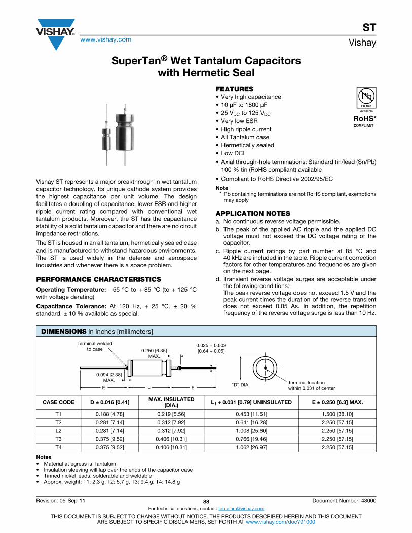
STwww.vishay.com Vishay
Revision: 05-Sep-11 88 Document Number: 43000
For technical questions, contact: [email protected]
THIS DOCUMENT IS SUBJECT TO CHANGE WITHOUT NOTICE. THE PRODUCTS DESCRIBED HEREIN AND THIS DOCUMENTARE SUBJECT TO SPECIFIC DISCLAIMERS, SET FORTH AT www.vishay.com/doc?91000
SuperTan® Wet Tantalum Capacitorswith Hermetic Seal
Vishay ST represents a major breakthrough in wet tantalumcapacitor technology. Its unique cathode system providesthe highest capacitance per unit volume. The designfacilitates a doubling of capacitance, lower ESR and higherripple current rating compared with conventional wettantalum products. Moreover, the ST has the capacitancestability of a solid tantalum capacitor and there are no circuitimpedance restrictions.
The ST is housed in an all tantalum, hermetically sealed caseand is manufactured to withstand hazardous environments.The ST is used widely in the defense and aerospaceindustries and whenever there is a space problem.
PERFORMANCE CHARACTERISTICSOperating Temperature: - 55 °C to + 85 °C (to + 125 °Cwith voltage derating)
Capacitance Tolerance: At 120 Hz, + 25 °C. ± 20 %standard. ± 10 % available as special.
FEATURES• Very high capacitance• 10 μF to 1800 μF• 25 VDC to 125 VDC
• Very low ESR• High ripple current• All Tantalum case• Hermetically sealed• Low DCL• Axial through-hole terminations: Standard tin/lead (Sn/Pb)
100 % tin (RoHS compliant) available
• Compliant to RoHS Directive 2002/95/EC
Note* Pb containing terminations are not RoHS compliant, exemptions
may apply
APPLICATION NOTESa. No continuous reverse voltage permissible.b. The peak of the applied AC ripple and the applied DC
voltage must not exceed the DC voltage rating of thecapacitor.
c. Ripple current ratings by part number at 85 °C and40 kHz are included in the table. Ripple current correctionfactors for other temperatures and frequencies are givenon the next page.
d. Transient reverse voltage surges are acceptable underthe following conditions:The peak reverse voltage does not exceed 1.5 V and thepeak current times the duration of the reverse transientdoes not exceed 0.05 As. In addition, the repetitionfrequency of the reverse voltage surge is less than 10 Hz.
Notes• Material at egress is Tantalum• Insulation sleeving will lap over the ends of the capacitor case• Tinned nickel leads, solderable and weldable• Approx. weight: T1: 2.3 g, T2: 5.7 g, T3: 9.4 g, T4: 14.8 g
DIMENSIONS in inches [millimeters]
CASE CODE D ± 0.016 [0.41] MAX. INSULATED(DIA.) L1 + 0.031 [0.79] UNINSULATED E ± 0.250 [6.3] MAX.
T1 0.188 [4.78] 0.219 [5.56] 0.453 [11.51] 1.500 [38.10]
T2 0.281 [7.14] 0.312 [7.92] 0.641 [16.28] 2.250 [57.15]
L2 0.281 [7.14] 0.312 [7.92] 1.008 [25.60] 2.250 [57.15]
T3 0.375 [9.52] 0.406 [10.31] 0.766 [19.46] 2.250 [57.15]
T4 0.375 [9.52] 0.406 [10.31] 1.062 [26.97] 2.250 [57.15]
L EETerminal locationwithin 0.031 of center
“D” DIA.
0.025 + 0.002[0.64 + 0.05]
Terminal weldedto case 0.250 [6.35]
MAX.
0.094 [2.38]MAX.
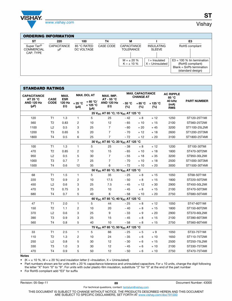
STwww.vishay.com Vishay
Revision: 05-Sep-11 89 Document Number: 43000
For technical questions, contact: [email protected]
THIS DOCUMENT IS SUBJECT TO CHANGE WITHOUT NOTICE. THE PRODUCTS DESCRIBED HEREIN AND THIS DOCUMENTARE SUBJECT TO SPECIFIC DISCLAIMERS, SET FORTH AT www.vishay.com/doc?91000
ORDERING INFORMATIONST 220 100 T4 M I E3
Super Tan®
COMMERCIALCAP. TYPE
CAPACITANCEμF
85 °C RATEDDC VOLTAGE
CASE CODE CAPACITANCETOLERANCE
INSULATINGSLEEVE
RoHS compliant
M = ± 20 %K = ± 10 %
I = InsulatedX = Uninsulated
E3 = 100 % tin termination(RoHS compliant)
Blank = SnPb termination(standard design)
STANDARD RATINGS
CAPACITANCEAT 25 °C
AND 120 Hz(μF)
CASECODE
MAX. ESR
120 Hz()
MAX. DCL AT MAX. IMP.AT - 55 °C
AND 120 Hz()
MAX. CAPACITANCE CHANGE AT
AC RIPPLE85 °C
40 kHz(mA)RMS
PART NUMBER+ 25 °C
(μA)
+ 85 °C/ + 125 °C
(μA)
- 55 °C (%)
+ 85 °C (%)
+ 125 °C(%)
25 VDC AT 85 °C; 15 VDC AT 125 °C
120 T1 1.3 1 5 25 - 42 + 8 + 12 1250 ST120-25T1MI
560 T2 0.83 2 10 12 - 65 + 10 + 15 2100 ST560-25T2MI
1100 L2 0.5 3 25 7 - 60 + 20 + 45 3200 ST1100-25L2MI
1200 T3 0.65 5 20 7 - 70 + 12 + 18 2600 ST1200-25T3MI
1800 T4 0.5 6 25 7 - 72 + 12 + 20 3100 ST1800-25T4MI
30 VDC AT 85 °C; 20 VDC AT 125 °C
100 T1 1.3 1 5 25 - 38 + 8 + 12 1200 ST100-30TMI
470 T2 0.85 2 10 15 - 65 + 10 + 18 1800 ST470-30T2MI
950 L2 0.5 5 30 7 - 55 + 18 + 35 3200 ST950-30L2MI
1000 T3 0.7 7 25 7 - 70 + 10 + 18 2500 ST1000-30T3MI
1500 T4 0.6 12 35 6 - 72 + 10 + 20 3000 ST1500-30T4MI
50 VDC AT 85 °C; 30 VDC AT 125 °C
68 T1 1.5 1 5 35 - 25 + 8 + 15 1050 ST68-50T1MI
220 T2 0.9 2 10 17.5 - 50 + 8 + 15 1800 ST220-50T2MI
450 L2 0.6 3 25 7.5 - 45 + 12 + 30 2900 ST450-50L2MI
470 T3 0.75 3 25 10 - 45 + 8 + 15 2100 ST470-50T3MI
680 T4 0.7 5 40 8 - 58 + 10 + 20 2750 ST680-50T4MI
60 VDC AT 85 °C; 40 VDC AT 125 °C
47 T1 2.0 1 5 44 - 25 + 8 + 12 1050 ST47-60T1MI
150 T2 1.1 2 10 20 - 40 + 8 + 15 1800 ST150-60T2MI
370 L2 0.6 3 25 9 - 33 + 9 + 20 2900 ST370-60L2MI
390 T3 0.9 3 25 15 - 45 + 8 + 15 2100 ST390-60T3MI
560 T4 0.8 5 40 10 - 58 + 8 + 15 2750 ST560-60T4MI
75 VDC AT 85 °C; 50 VDC AT 125 °C
33 T1 2.5 1 5 66 - 25 + 5 + 9 1050 ST33-75T1MI
110 T2 1.3 2 10 24 - 35 + 6 + 10 1650 ST110-75T2MI
250 L2 0.8 5 30 12 - 30 + 6 + 15 2500 ST250-75L2MI
330 T3 1.0 3 30 12 - 45 + 6 + 10 2100 ST330-75T3MI
470 T4 0.9 5 50 12 - 50 + 6 + 10 2750 ST470-75T4MI
Notes• (K = ± 10 %, M = ± 20 %) and insulation letter (I =Insulation, X = Uninsulated)• Part numbers shown are for units with ± 20 % capacitance tolerance and uninsulated capacitors. For ± 10 units, change the digit following
the letter “X” from “0” to “9”. For units with outer plastic-film insulation, substitute “2” for “0” at the end of the part number• For RoHS compliant add “E3” for suffix
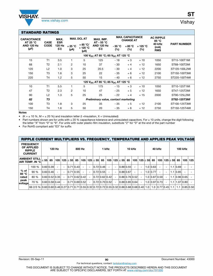
STwww.vishay.com Vishay
Revision: 05-Sep-11 90 Document Number: 43000
For technical questions, contact: [email protected]
THIS DOCUMENT IS SUBJECT TO CHANGE WITHOUT NOTICE. THE PRODUCTS DESCRIBED HEREIN AND THIS DOCUMENTARE SUBJECT TO SPECIFIC DISCLAIMERS, SET FORTH AT www.vishay.com/doc?91000
100 VDC AT 85 °C; 65 VDC AT 125 °C
15 T1 3.5 1 5 125 - 18 + 3 + 10 1050 ST15-100T1MI
68 T2 2.1 2 10 37 - 30 + 4 + 12 1650 ST68-100T2MI
120 L2 1.0 3 25 20.5 - 30 + 4 + 12 2200 ST120-100L2MI
150 T3 1.6 3 25 22 - 35 + 6 + 12 2100 ST150-100T3MI
220 T4 1.2 5 50 15 - 40 + 6 + 12 2750 ST220-100T4MI
125 VDC AT 85 °C; 85 VDC AT 125 °C
10 T1 5.5 1 5 175 - 15 + 3 + 10 1050 ST10-125T1MI
47 T2 2.3 2 10 47 - 25 + 5 + 12 1650 ST47-125T2MI
90 L2 1.3 5 25 25 - 22 + 4 + 15 2000 ST90-125L2MI
82 T3 Preliminary value, contact marketing ST82-125T3MI
100 T3 1.8 3 25 35 - 35 + 5 + 12 2100 ST100-125T3MI
150 T4 1.6 5 50 20 - 35 + 6 + 12 2750 ST150-125T4MI
RIPPLE CURRENT MULTIPLIERS VS. FREQUENCY, TEMPERATURE AND APPLIES PEAK VOLTAGEFREQUENCYOF APPLIED
RIPPLECURRENT
120 Hz 800 Hz 1 kHz 10 kHz 40 kHz 100 kHz
AMBIENT STILLAIR TEMP. IN °C 55 85 105 125 55 85 105 125 55 85 105 125 55 85 105 125 55 85 105 125 55 85 105 125
% of85 °Cratedpeak
voltage
100 % 0.60 0.39 - - 0.71 0.43 - - 0.72 0.46 - - 0.88 0.55 - - 1.0 0.63 - - 1.1 0.69 - -
90 % 0.60 0.46 - - 0.71 0.55 - - 0.72 0.55 - - 0.88 0.67 - - 1.0 0.77 - - 1.1 0.85 - -
80 % 0.60 0.52 0.35 - 0.71 0.62 0.42 - 0.72 0.62 0.42 - 0.88 0.76 0.52 - 1.0 0.87 0.59 - 1.1 0.96 0.65 -
70 % 0.60 0.58 0.44 - 0.71 0.69 0.52 - 0.72 0.70 0.52 - 0.88 0.85 0.64 - 1.0 0.97 0.73 - 1.1 1.07 0.80 -
66 2/3 % 0.60 0.60 0.46 0.27 0.71 0.71 0.55 0.32 0.72 0.72 0.55 0.32 0.88 0.88 0.68 0.40 1.0 1.0 0.77 0.45 1.1 1.1 0.85 0.50
STANDARD RATINGS
CAPACITANCEAT 25 °C
AND 120 Hz(μF)
CASECODE
MAX. ESR
120 Hz()
MAX. DCL AT MAX. IMP.AT - 55 °C
AND 120 Hz()
MAX. CAPACITANCE CHANGE AT
AC RIPPLE85 °C
40 kHz(mA)RMS
PART NUMBER+ 25 °C
(μA)
+ 85 °C/ + 125 °C
(μA)
- 55 °C (%)
+ 85 °C (%)
+ 125 °C(%)
Notes• (K = ± 10 %, M = ± 20 %) and insulation letter (I =Insulation, X = Uninsulated)• Part numbers shown are for units with ± 20 % capacitance tolerance and uninsulated capacitors. For ± 10 units, change the digit following
the letter “X” from “0” to “9”. For units with outer plastic-film insulation, substitute “2” for “0” at the end of the part number• For RoHS compliant add “E3” for suffix
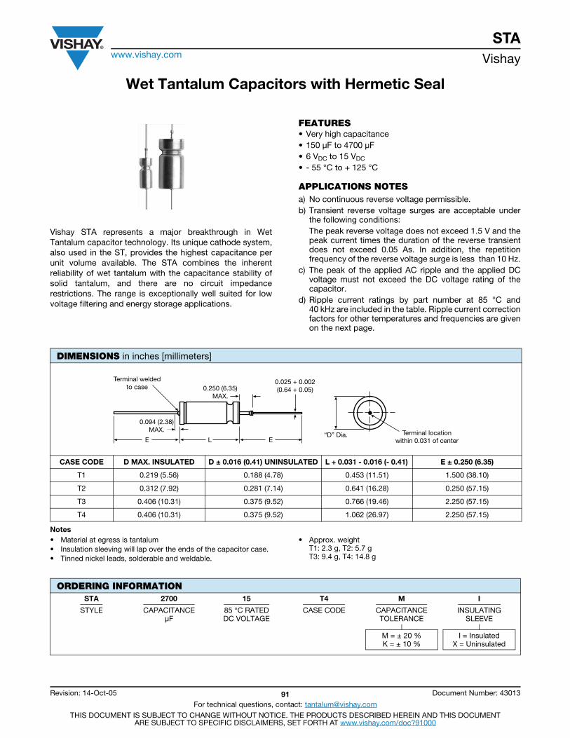
STAwww.vishay.com Vishay
Revision: 14-Oct-05 91 Document Number: 43013
For technical questions, contact: [email protected] DOCUMENT IS SUBJECT TO CHANGE WITHOUT NOTICE. THE PRODUCTS DESCRIBED HEREIN AND THIS DOCUMENT
ARE SUBJECT TO SPECIFIC DISCLAIMERS, SET FORTH AT www.vishay.com/doc?91000
Wet Tantalum Capacitors with Hermetic Seal
Vishay STA represents a major breakthrough in WetTantalum capacitor technology. Its unique cathode system,also used in the ST, provides the highest capacitance perunit volume available. The STA combines the inherentreliability of wet tantalum with the capacitance stability ofsolid tantalum, and there are no circuit impedancerestrictions. The range is exceptionally well suited for lowvoltage filtering and energy storage applications.
FEATURES• Very high capacitance• 150 μF to 4700 μF• 6 VDC to 15 VDC
• - 55 °C to + 125 °C
APPLICATIONS NOTESa) No continuous reverse voltage permissible.b) Transient reverse voltage surges are acceptable under
the following conditions:The peak reverse voltage does not exceed 1.5 V and thepeak current times the duration of the reverse transientdoes not exceed 0.05 As. In addition, the repetitionfrequency of the reverse voltage surge is less than 10 Hz.
c) The peak of the applied AC ripple and the applied DCvoltage must not exceed the DC voltage rating of thecapacitor.
d) Ripple current ratings by part number at 85 °C and40 kHz are included in the table. Ripple current correctionfactors for other temperatures and frequencies are givenon the next page.
Notes• Material at egress is tantalum• Insulation sleeving will lap over the ends of the capacitor case.• Tinned nickel leads, solderable and weldable.
• Approx. weightT1: 2.3 g, T2: 5.7 gT3: 9.4 g, T4: 14.8 g
DIMENSIONS in inches [millimeters]
CASE CODE D MAX. INSULATED D ± 0.016 (0.41) UNINSULATED L + 0.031 - 0.016 (- 0.41) E ± 0.250 (6.35)
T1 0.219 (5.56) 0.188 (4.78) 0.453 (11.51) 1.500 (38.10)
T2 0.312 (7.92) 0.281 (7.14) 0.641 (16.28) 0.250 (57.15)
T3 0.406 (10.31) 0.375 (9.52) 0.766 (19.46) 2.250 (57.15)
T4 0.406 (10.31) 0.375 (9.52) 1.062 (26.97) 2.250 (57.15)
0.025 + 0.002(0.64 + 0.05)0.250 (6.35)
MAX.
ELE
0.094 (2.38)MAX.
Terminal weldedto case
Terminal locationwithin 0.031 of center
“D” Dia.
ORDERING INFORMATIONSTA 2700 15 T4 M I
STYLE CAPACITANCEμF
85 °C RATEDDC VOLTAGE
CASE CODE CAPACITANCE TOLERANCE
INSULATING SLEEVE
M = ± 20 %K = ± 10 %
I = InsulatedX = Uninsulated
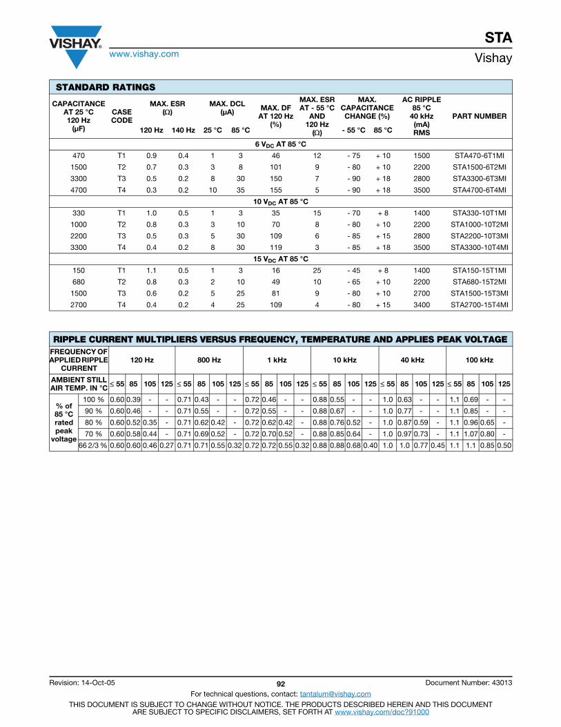
STAwww.vishay.com Vishay
Revision: 14-Oct-05 92 Document Number: 43013
For technical questions, contact: [email protected] DOCUMENT IS SUBJECT TO CHANGE WITHOUT NOTICE. THE PRODUCTS DESCRIBED HEREIN AND THIS DOCUMENT
ARE SUBJECT TO SPECIFIC DISCLAIMERS, SET FORTH AT www.vishay.com/doc?91000
STANDARD RATINGS
CAPACITANCEAT 25 °C 120 Hz
(μF)
CASECODE
MAX. ESR()
MAX. DCL (μA) MAX. DF
AT 120 Hz(%)
MAX. ESRAT - 55 °C
AND120 Hz
()
MAX.CAPACITANCECHANGE (%)
AC RIPPLE 85 °C
40 kHz(mA)RMS
PART NUMBER
120 Hz 140 Hz 25 °C 85 °C - 55 °C 85 °C
6 VDC AT 85 °C
470 T1 0.9 0.4 1 3 46 12 - 75 + 10 1500 STA470-6T1MI
1500 T2 0.7 0.3 3 8 101 9 - 80 + 10 2200 STA1500-6T2MI
3300 T3 0.5 0.2 8 30 150 7 - 90 + 18 2800 STA3300-6T3MI
4700 T4 0.3 0.2 10 35 155 5 - 90 + 18 3500 STA4700-6T4MI
10 VDC AT 85 °C
330 T1 1.0 0.5 1 3 35 15 - 70 + 8 1400 STA330-10T1MI
1000 T2 0.8 0.3 3 10 70 8 - 80 + 10 2200 STA1000-10T2MI
2200 T3 0.5 0.3 5 30 109 6 - 85 + 15 2800 STA2200-10T3MI
3300 T4 0.4 0.2 8 30 119 3 - 85 + 18 3500 STA3300-10T4MI
15 VDC AT 85 °C
150 T1 1.1 0.5 1 3 16 25 - 45 + 8 1400 STA150-15T1MI
680 T2 0.8 0.3 2 10 49 10 - 65 + 10 2200 STA680-15T2MI
1500 T3 0.6 0.2 5 25 81 9 - 80 + 10 2700 STA1500-15T3MI
2700 T4 0.4 0.2 4 25 109 4 - 80 + 15 3400 STA2700-15T4MI
RIPPLE CURRENT MULTIPLIERS VERSUS FREQUENCY, TEMPERATURE AND APPLIES PEAK VOLTAGEFREQUENCY OF APPLIED RIPPLE
CURRENT120 Hz 800 Hz 1 kHz 10 kHz 40 kHz 100 kHz
AMBIENT STILL AIR TEMP. IN °C 55 85 105 125 55 85 105 125 55 85 105 125 55 85 105 125 55 85 105 125 55 85 105 125
% of 85 °C rated peak
voltage
100 % 0.60 0.39 - - 0.71 0.43 - - 0.72 0.46 - - 0.88 0.55 - - 1.0 0.63 - - 1.1 0.69 - -
90 % 0.60 0.46 - - 0.71 0.55 - - 0.72 0.55 - - 0.88 0.67 - - 1.0 0.77 - - 1.1 0.85 - -
80 % 0.60 0.52 0.35 - 0.71 0.62 0.42 - 0.72 0.62 0.42 - 0.88 0.76 0.52 - 1.0 0.87 0.59 - 1.1 0.96 0.65 -
70 % 0.60 0.58 0.44 - 0.71 0.69 0.52 - 0.72 0.70 0.52 - 0.88 0.85 0.64 - 1.0 0.97 0.73 - 1.1 1.07 0.80 -
66 2/3 % 0.60 0.60 0.46 0.27 0.71 0.71 0.55 0.32 0.72 0.72 0.55 0.32 0.88 0.88 0.68 0.40 1.0 1.0 0.77 0.45 1.1 1.1 0.85 0.50
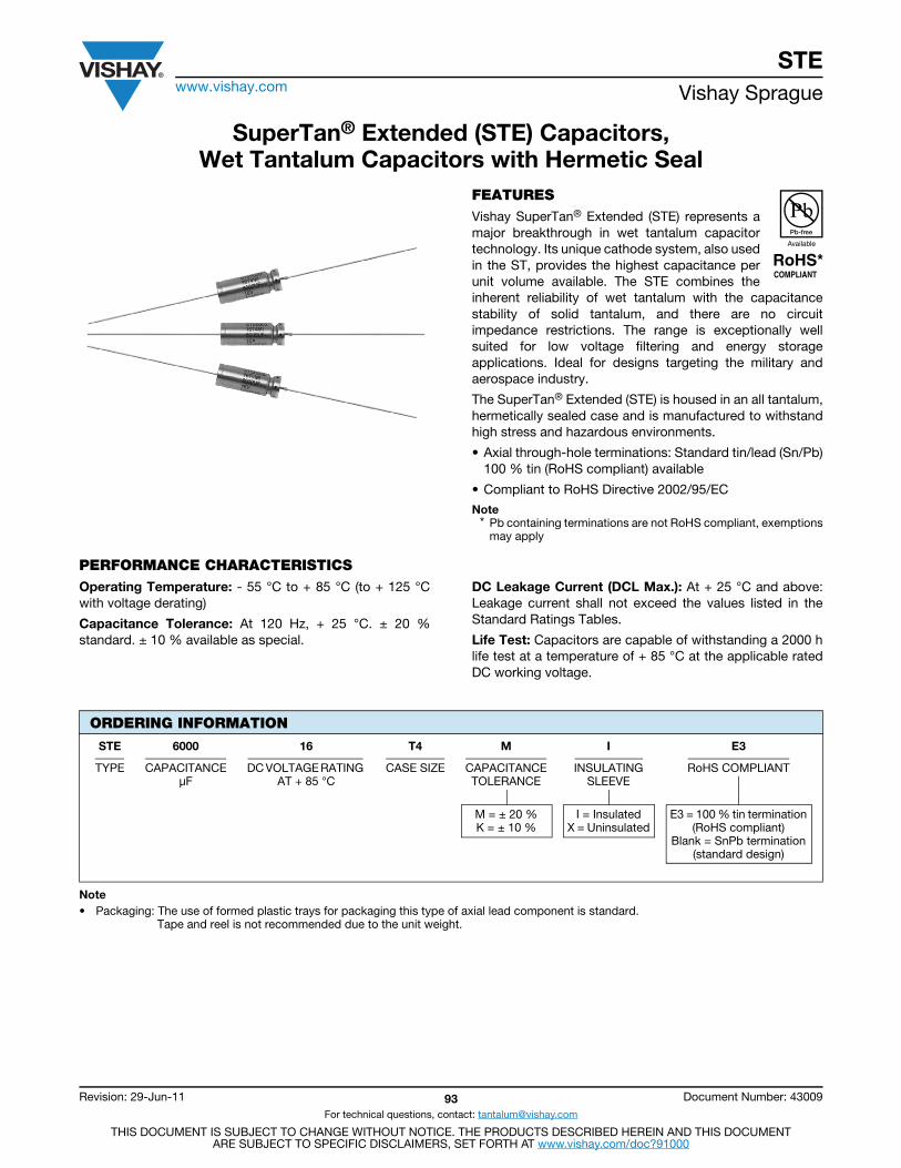
STEwww.vishay.com Vishay Sprague
Revision: 29-Jun-11 93 Document Number: 43009
For technical questions, contact: [email protected]
THIS DOCUMENT IS SUBJECT TO CHANGE WITHOUT NOTICE. THE PRODUCTS DESCRIBED HEREIN AND THIS DOCUMENTARE SUBJECT TO SPECIFIC DISCLAIMERS, SET FORTH AT www.vishay.com/doc?91000
SuperTan® Extended (STE) Capacitors,Wet Tantalum Capacitors with Hermetic Seal
FEATURESVishay SuperTan® Extended (STE) represents amajor breakthrough in wet tantalum capacitortechnology. Its unique cathode system, also usedin the ST, provides the highest capacitance perunit volume available. The STE combines theinherent reliability of wet tantalum with the capacitancestability of solid tantalum, and there are no circuitimpedance restrictions. The range is exceptionally wellsuited for low voltage filtering and energy storageapplications. Ideal for designs targeting the military andaerospace industry.
The SuperTan® Extended (STE) is housed in an all tantalum,hermetically sealed case and is manufactured to withstandhigh stress and hazardous environments.
• Axial through-hole terminations: Standard tin/lead (Sn/Pb)100 % tin (RoHS compliant) available
• Compliant to RoHS Directive 2002/95/EC
Note* Pb containing terminations are not RoHS compliant, exemptions
may apply
PERFORMANCE CHARACTERISTICSOperating Temperature: - 55 °C to + 85 °C (to + 125 °Cwith voltage derating)
Capacitance Tolerance: At 120 Hz, + 25 °C. ± 20 %standard. ± 10 % available as special.
DC Leakage Current (DCL Max.): At + 25 °C and above:Leakage current shall not exceed the values listed in theStandard Ratings Tables.
Life Test: Capacitors are capable of withstanding a 2000 hlife test at a temperature of + 85 °C at the applicable ratedDC working voltage.
Note• Packaging: The use of formed plastic trays for packaging this type of axial lead component is standard.
Tape and reel is not recommended due to the unit weight.
ORDERING INFORMATION
STE 6000 16 T4 M I E3
TYPE CAPACITANCEμF
DC VOLTAGE RATING AT + 85 °C
CASE SIZE CAPACITANCETOLERANCE
INSULATINGSLEEVE
RoHS COMPLIANT
M = ± 20 %K = ± 10 %
I = InsulatedX = Uninsulated
E3 = 100 % tin termination(RoHS compliant)
Blank = SnPb termination(standard design)
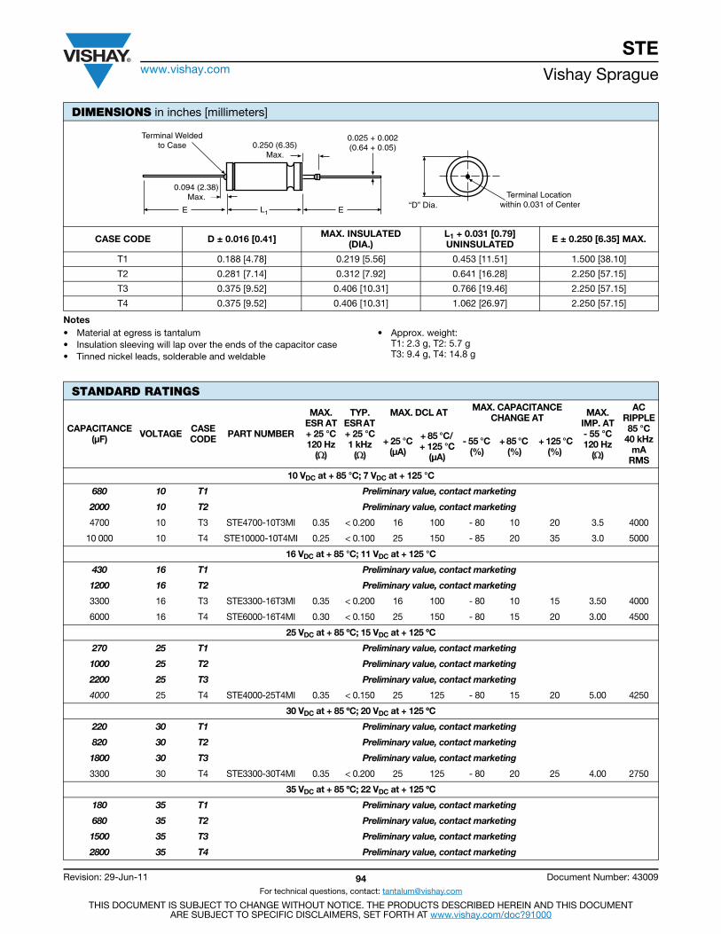
STEwww.vishay.com Vishay Sprague
Revision: 29-Jun-11 94 Document Number: 43009
For technical questions, contact: [email protected]
THIS DOCUMENT IS SUBJECT TO CHANGE WITHOUT NOTICE. THE PRODUCTS DESCRIBED HEREIN AND THIS DOCUMENTARE SUBJECT TO SPECIFIC DISCLAIMERS, SET FORTH AT www.vishay.com/doc?91000
Notes• Material at egress is tantalum• Insulation sleeving will lap over the ends of the capacitor case• Tinned nickel leads, solderable and weldable
• Approx. weight:T1: 2.3 g, T2: 5.7 gT3: 9.4 g, T4: 14.8 g
DIMENSIONS in inches [millimeters]
CASE CODE D ± 0.016 [0.41] MAX. INSULATED(DIA.)
L1 + 0.031 [0.79]UNINSULATED E ± 0.250 [6.35] MAX.
T1 0.188 [4.78] 0.219 [5.56] 0.453 [11.51] 1.500 [38.10]
T2 0.281 [7.14] 0.312 [7.92] 0.641 [16.28] 2.250 [57.15]
T3 0.375 [9.52] 0.406 [10.31] 0.766 [19.46] 2.250 [57.15]
T4 0.375 [9.52] 0.406 [10.31] 1.062 [26.97] 2.250 [57.15]
“D” Dia.
Terminal Weldedto Case 0.250 (6.35)
Max.
0.094 (2.38)Max.
0.025 + 0.002(0.64 + 0.05)
E EL1
Terminal Location within 0.031 of Center
STANDARD RATINGS
CAPACITANCE(μF) VOLTAGE CASE
CODE PART NUMBER
MAX. ESR AT+ 25 °C120 Hz
()
TYP. ESR AT + 25 °C1 kHz
()
MAX. DCL AT MAX. CAPACITANCE CHANGE AT MAX.
IMP. AT- 55 °C120 Hz
()
AC RIPPLE85 °C
40 kHzmA
RMS
+ 25 °C(μA)
+ 85 °C/ + 125 °C
(μA)
- 55 °C (%)
+ 85 °C (%)
+ 125 °C(%)
10 VDC at + 85 °C; 7 VDC at + 125 °C
680 10 T1 Preliminary value, contact marketing
2000 10 T2 Preliminary value, contact marketing
4700 10 T3 STE4700-10T3MI 0.35 < 0.200 16 100 - 80 10 20 3.5 4000
10 000 10 T4 STE10000-10T4MI 0.25 < 0.100 25 150 - 85 20 35 3.0 5000
16 VDC at + 85 °C; 11 VDC at + 125 °C
430 16 T1 Preliminary value, contact marketing
1200 16 T2 Preliminary value, contact marketing
3300 16 T3 STE3300-16T3MI 0.35 < 0.200 16 100 - 80 10 15 3.50 4000
6000 16 T4 STE6000-16T4MI 0.30 < 0.150 25 150 - 80 15 20 3.00 4500
25 VDC at + 85 ºC; 15 VDC at + 125 ºC
270 25 T1 Preliminary value, contact marketing
1000 25 T2 Preliminary value, contact marketing
2200 25 T3 Preliminary value, contact marketing
4000 25 T4 STE4000-25T4MI 0.35 < 0.150 25 125 - 80 15 20 5.00 4250
30 VDC at + 85 ºC; 20 VDC at + 125 ºC
220 30 T1 Preliminary value, contact marketing
820 30 T2 Preliminary value, contact marketing
1800 30 T3 Preliminary value, contact marketing
3300 30 T4 STE3300-30T4MI 0.35 < 0.200 25 125 - 80 20 25 4.00 2750
35 VDC at + 85 ºC; 22 VDC at + 125 ºC
180 35 T1 Preliminary value, contact marketing
680 35 T2 Preliminary value, contact marketing
1500 35 T3 Preliminary value, contact marketing
2800 35 T4 Preliminary value, contact marketing

STEwww.vishay.com Vishay Sprague
Revision: 29-Jun-11 95 Document Number: 43009
For technical questions, contact: [email protected]
THIS DOCUMENT IS SUBJECT TO CHANGE WITHOUT NOTICE. THE PRODUCTS DESCRIBED HEREIN AND THIS DOCUMENTARE SUBJECT TO SPECIFIC DISCLAIMERS, SET FORTH AT www.vishay.com/doc?91000
50 VDC at + 85 ºC; 30 VDC at + 125 ºC
110 50 T1 Preliminary value, contact marketing
350 50 T2 Preliminary value, contact marketing
900 50 T3 Preliminary value, contact marketing
1500 50 T4 STE1500-50T4MI 0.35 < 0.215 15 110 - 70 20 20 6.00 3500
2200 50 T4 STE2200-50T4MI 0.60 < 0.400 25 125 - 80 25 30 4.50 3000
60 VDC at + 85 °C; 40 VDC at + 125 °C
68 60 T1 Preliminary value, contact marketing
220 60 T2 Preliminary value, contact marketing
560 60 T3 Preliminary value, contact marketing
1000 60 T4 STE1000-60T4MI 0.50 < 0.300 20 120 - 40 10 15 5.50 3500
75 VDC at + 85 ºC; 50 VDC at + 125 ºC
56 75 T1 Preliminary value, contact marketing
180 75 T2 STE180-75T2MI 1.50 < 0.500 5 25 - 35 15 20 30.00 2000
470 75 T3 STE470-75T3MI 0.60 < 0.325 25 100 - 45 10 25 10.00 3000
750 75 T4 STE750-75T4MI 0.50 < 0.400 20 120 - 35 10 15 6.50 3500
100 VDC at + 85 °C; 65 VDC at + 125 °C
27 100 T1 Preliminary value, contact marketing
86 100 T2 Preliminary value, contact marketing
220 100 T3 Preliminary value, contact marketing
400 100 T4 STE400-100T4MI 0.70 < 0.400 10 120 - 40 6 12 15.00 3000
125 VDC at + 85 ºC; 85 VDC at + 125 ºC
18 125 T1 Preliminary value, contact marketing
56 125 T2 Preliminary value, contact marketing
150 125 T3 Preliminary value, contact marketing
240 125 T4 STE240-125T4MI 0.80 < 0.600 15 150 - 35 6 12 20.00 2500
STANDARD RATINGS
CAPACITANCE(μF) VOLTAGE CASE
CODE PART NUMBER
MAX. ESR AT+ 25 °C120 Hz
()
TYP. ESR AT + 25 °C1 kHz
()
MAX. DCL AT MAX. CAPACITANCE CHANGE AT MAX.
IMP. AT- 55 °C120 Hz
()
AC RIPPLE85 °C
40 kHzmA
RMS
+ 25 °C(μA)
+ 85 °C/ + 125 °C
(μA)
- 55 °C (%)
+ 85 °C (%)
+ 125 °C(%)
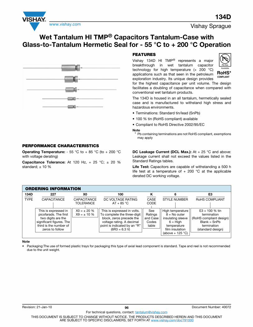
134Dwww.vishay.com Vishay Sprague
Revision: 21-Jan-10 96 Document Number: 40072
For technical questions, contact: [email protected] DOCUMENT IS SUBJECT TO CHANGE WITHOUT NOTICE. THE PRODUCTS DESCRIBED HEREIN AND THIS DOCUMENT
ARE SUBJECT TO SPECIFIC DISCLAIMERS, SET FORTH AT www.vishay.com/doc?91000
Wet Tantalum HI TMP® Capacitors Tantalum-Case with Glass-to-Tantalum Hermetic Seal for - 55 °C to + 200 °C Operation
FEATURESVishay 134D HI TMP® represents a majorbreakthrough in wet tantalum capacitortechnology for high temperature (+ 200 °C)applications such as that seen in the petroleumexploration industry. Its unique design providesfor the highest capacitance per unit volume. The designfacilitates a doubling of capacitance when compared withconventional wet tantalum products.
The 134D is housed in an all tantalum, hermetically sealedcase and is manufactured to withstand high stress andhazardous environments.
• Terminations: Standard tin/lead (SnPb)
• 100 % tin (RoHS compliant) available
• Compliant to RoHS Directive 2002/95/EC
Note* Pb containing terminations are not RoHS compliant, exemptions
may apply
PERFORMANCE CHARACTERISTICSOperating Temperature: - 55 °C to + 85 °C (to + 200 °Cwith voltage derating)
Capacitance Tolerance: At 120 Hz, + 25 °C; ± 20 %standard; ± 10 %
DC Leakage Current (DCL Max.): At + 25 °C and above:Leakage current shall not exceed the values listed in theStandard Ratings tables.
Life Test: Capacitors are capable of withstanding a 500 hlife test at a temperature of + 200 °C at the applicablederated DC working voltage.
Note• Packaging:The use of formed plastic trays for packaging this type of axial lead component is standard. Tape and reel is not recommended
due to the unit weight.
ORDERING INFORMATION134D 227 X0 100 K 6 E3
TYPE CAPACITANCE CAPACITANCETOLERANCE
DC VOLTAGE RATINGAT + 85 °C
CASECODE
STYLE NUMBER RoHS COMPLIANT
This is expressed inpicofarads. The first
two digits are thesignificant figures. Thethird is the number of
zeros to follow
X0 = ± 20 %X9 = ± 10 %
This is expressed in volts.To complete the three-digitblock, zeros precede thevoltage rating. A decimal
point is indicated by an “R”(6R3 = 6.3 V)
SeeRatings
and CaseCodestable
High temperature8 = No outer
insulating sleeve6 = High
temperaturefilm insulation
(above + 125 °C)
E3 = 100 % tintermination
(RoHS compliant design)Blank = SnPbtermination
(standard design)
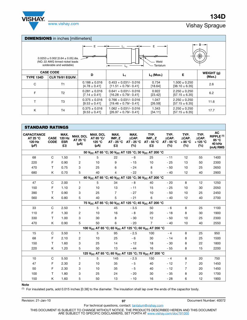
134Dwww.vishay.com Vishay Sprague
Revision: 21-Jan-10 97 Document Number: 40072
For technical questions, contact: [email protected] DOCUMENT IS SUBJECT TO CHANGE WITHOUT NOTICE. THE PRODUCTS DESCRIBED HEREIN AND THIS DOCUMENT
ARE SUBJECT TO SPECIFIC DISCLAIMERS, SET FORTH AT www.vishay.com/doc?91000
Note(1) For insulated parts, add 0.015 inches [0.38] to the diameter. The insulation shall lap over the ends of the capacitor body.
DIMENSIONS in inches [millimeters]
CASE CODED L1 L2 (Max.) E WEIGHT (g)
(Max.)TYPE 134D CLR 79/81 EQUIV.
C T1 0.188 ± 0.016 [4.78 ± 0.41]
0.453 + 0.031/- 0.016[11.51 + 0.79/- 0.41]
0.734 [18.64]
1.500 ± 0.250 [38.10 ± 6.35] 2.6
F T2 0.281 ± 0.016 [7.14 ± 0.41]
0.641 + 0.031/- 0.016[16.28 + 0.79/- 0.41]
0.922[23.42]
2.250 ± 0.250 [57.15 ± 6.35] 6.2
T T3 0.375 ± 0.016 [9.53 ± 0.41]
0.766 + 0.031/- 0.016[19.46 + 0.79/- 0.41]
1.047[26.59]
2.250 ± 0.250 [57.15 ± 6.35] 11.6
K T4 0.375 ± 0.016 [9.53 ± 0.41]
1.062 + 0.031/- 0.016[26.97 + 0.79/- 0.41]
1.343 [34.11]
2.250 ± 0.250 [57.15 ± 6.35] 17.7
STANDARD RATINGS
CAPACITANCEAT 25 °C 120 Hz
(μF)
CASECODE
MAX.120 Hz
ESR()
MAX. DCLAT 25 °C
(μA)
MAX. DCLAT 85 °C/
125 °C(μA)
MAX.IMP, Z
AT - 25 °C ()
MAX.CAP.
AT - 25 °C(%)
TYP.IMP., Z
AT - 55 °C ()
TYP.CAP.
AT - 55 °C (%)
TYP.CAP.+ 85 °C
(%)
TYP.CAP.
+ 125 °C (%)
ACRIPPLE (1)
85 °C40 kHz
(mA) RMS
50 VDC AT 85 °C; 30 VDC AT 125 °C; 30 VDC AT 200 °C
68 C 1.50 1 5 22 - 6 25 - 11 12 55 1400
220 F 0.90 2 10 9 - 15 10 - 25 13 50 2300
470 T 0.75 3 25 6 - 24 8 - 50 10 25 2650
680 K 0.70 5 40 4 - 22 5 - 40 12 40 2900
60 VDC AT 85 °C; 40 VDC AT 125 °C; 36 VDC AT 200 °C
47 C 2.00 1 5 34 - 8 40 - 20 8 12 1250
150 F 1.10 2 10 13 - 11 15 - 25 10 30 2050
390 T 0.90 3 25 7 - 27 10 - 50 10 25 2450
560 K 0.80 5 40 5 - 21 6 - 40 12 40 2700
75 VDC AT 85 °C; 50 VDC AT 125 °C; 45 VDC AT 200 °C
33 C 2.50 1 5 45 - 3.5 50 - 6 8 25 1100
110 F 1.30 2 10 16 - 8 20 - 18 8 30 1900
330 T 1.00 3 30 8 - 30 12 - 50 10 25 2300
470 K 0.90 5 50 6 - 20 7 - 40 10 40 2550
100 VDC AT 85 °C; 65 VDC AT 125 °C; 60 VDC AT 200 °C
15 C 3.50 1 5 95 - 2.5 100 - 4 8 25 950
68 F 2.10 2 10 25 - 6 30 - 14 8 25 1500
150 T 1.60 3 25 14 - 12 18 - 30 8 22 1800
220 K 1.20 5 50 13 - 44 16 - 55 8 15 2200
125 VDC AT 85 °C; 85 VDC AT 125 °C; 75 VDC AT 200 °C
10 C 5.50 1 5 145 - 2.5 150 - 4 8 20 750
47 F 2.30 2 10 35 - 5 40 - 12 7 20 1450
50 F 2.30 3 10 35 - 5 40 - 12 7 20 1450
100 T 1.80 3 25 24 - 20 30 - 35 8 20 1700
150 K 1.60 5 50 13 - 10 16 - 28 6 12 1900
L2
WeldTantalum
0.0253 ± 0.002 [0.64 ± 0.05] dia.(NO. 22 AWG tinned nickel leads
solderable and weldable)
DE L1 E
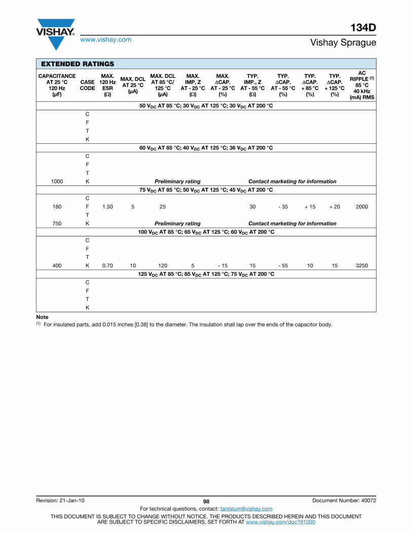
134Dwww.vishay.com Vishay Sprague
Revision: 21-Jan-10 98 Document Number: 40072
For technical questions, contact: [email protected] DOCUMENT IS SUBJECT TO CHANGE WITHOUT NOTICE. THE PRODUCTS DESCRIBED HEREIN AND THIS DOCUMENT
ARE SUBJECT TO SPECIFIC DISCLAIMERS, SET FORTH AT www.vishay.com/doc?91000
Note(1) For insulated parts, add 0.015 inches [0.38] to the diameter. The insulation shall lap over the ends of the capacitor body.
EXTENDED RATINGS
CAPACITANCEAT 25 °C 120 Hz
(μF)
CASECODE
MAX.120 Hz
ESR()
MAX. DCLAT 25 °C
(μA)
MAX. DCLAT 85 °C/
125 °C(μA)
MAX.IMP, Z
AT - 25 °C ()
MAX.CAP.
AT - 25 °C(%)
TYP.IMP., Z
AT - 55 °C ()
TYP.CAP.
AT - 55 °C (%)
TYP.CAP.+ 85 °C
(%)
TYP.CAP.
+ 125 °C (%)
ACRIPPLE (1)
85 °C40 kHz
(mA) RMS
50 VDC AT 85 °C; 30 VDC AT 125 °C; 30 VDC AT 200 °C
C
F
T
K
60 VDC AT 85 °C; 40 VDC AT 125 °C; 36 VDC AT 200 °C
C
F
T
1000 K Preliminary rating Contact marketing for information
75 VDC AT 85 °C; 50 VDC AT 125 °C; 45 VDC AT 200 °C
C
180 F 1.50 5 25 30 - 35 + 15 + 20 2000
T
750 K Preliminary rating Contact marketing for information
100 VDC AT 85 °C; 65 VDC AT 125 °C; 60 VDC AT 200 °C
C
F
T
400 K 0.70 10 120 5 - 15 15 - 55 10 15 3250
125 VDC AT 85 °C; 85 VDC AT 125 °C; 75 VDC AT 200 °C
C
F
T
K
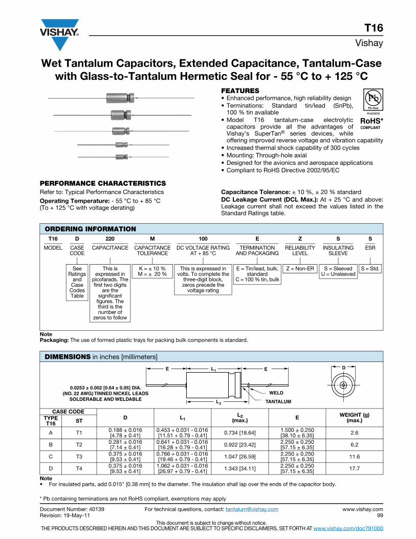
Document Number: 40139 For technical questions, contact: [email protected] www.vishay.comRevision: 19-May-11 99
This document is subject to change without notice. THE PRODUCTS DESCRIBED HEREIN AND THIS DOCUMENT ARE SUBJECT TO SPECIFIC DISCLAIMERS, SET FORTH AT www.vishay.com/doc?91000
Wet Tantalum Capacitors, Extended Capacitance, Tantalum-Casewith Glass-to-Tantalum Hermetic Seal for - 55 °C to + 125 °C
T16Vishay
FEATURES• Enhanced performance, high reliability design• Terminations: Standard tin/lead (SnPb),
100 % tin available• Model T16 tantalum-case electrolytic
capacitors provide all the advantages ofVishay’s SuperTan® series devices, whileoffering improved reverse voltage and vibration capability
• Increased thermal shock capability of 300 cycles• Mounting: Through-hole axial• Designed for the avionics and aerospace applications• Compliant to RoHS Directive 2002/95/EC
PERFORMANCE CHARACTERISTICSRefer to: Typical Performance CharacteristicsOperating Temperature: - 55 °C to + 85 °C (To + 125 °C with voltage derating)
Capacitance Tolerance: ± 10 %, ± 20 % standardDC Leakage Current (DCL Max.): At + 25 °C and above:Leakage current shall not exceed the values listed in theStandard Ratings table.
NotePackaging: The use of formed plastic trays for packing bulk components is standard.
Note• For insulated parts, add 0.015" [0.38 mm] to the diameter. The insulation shall lap over the ends of the capacitor body.
ORDERING INFORMATIONT16 D 220 M 100 E Z S S
MODEL CASECODE
CAPACITANCE CAPACITANCETOLERANCE
DC VOLTAGE RATINGAT + 85 °C
TERMINATIONAND PACKAGING
RELIABILITYLEVEL
INSULATINGSLEEVE
ESR
SeeRatings
and Case
CodesTable
This isexpressed in
picofarads. Thefirst two digits
are thesignificant
figures. Thethird is thenumber of
zeros to follow
K = ± 10 %M = ± 20 %
This is expressed involts. To complete the
three-digit block,zeros precede the
voltage rating
E = Tin/lead, bulk,standard
C = 100 % tin, bulk
Z = Non-ER S = SleevedU = Unsleeved
S = Std.
DIMENSIONS in inches [millimeters]
CASE CODE D L1
L2(max.) E WEIGHT (g)
(max.) TYPE T16 ST
A T1 0.188 ± 0.016 [4.78 ± 0.41]
0.453 + 0.031 - 0.016 [11.51 + 0.79 - 0.41] 0.734 [18.64] 1.500 ± 0.250
[38.10 ± 6.35] 2.6
B T2 0.281 ± 0.016 [7.14 ± 0.41]
0.641 + 0.031 - 0.016 [16.28 + 0.79 - 0.41] 0.922 [23.42] 2.250 ± 0.250
[57.15 ± 6.35] 6.2
C T3 0.375 ± 0.016 [9.53 ± 0.41]
0.766 + 0.031 - 0.016 [19.46 + 0.79 - 0.41] 1.047 [26.59] 2.250 ± 0.250
[57.15 ± 6.35] 11.6
D T4 0.375 ± 0.016 [9.53 ± 0.41]
1.062 + 0.031 - 0.016 [26.97 + 0.79 - 0.41] 1.343 [34.11] 2.250 ± 0.250
[57.15 ± 6.35] 17.7
DE E
L2
L1
TANTALUM
WELD0.0253 ± 0.002 [0.64 ± 0.05] DIA.
(NO. 22 AWG) TINNED NICKEL LEADSSOLDERABLE AND WELDABLE
* Pb containing terminations are not RoHS compliant, exemptions may apply
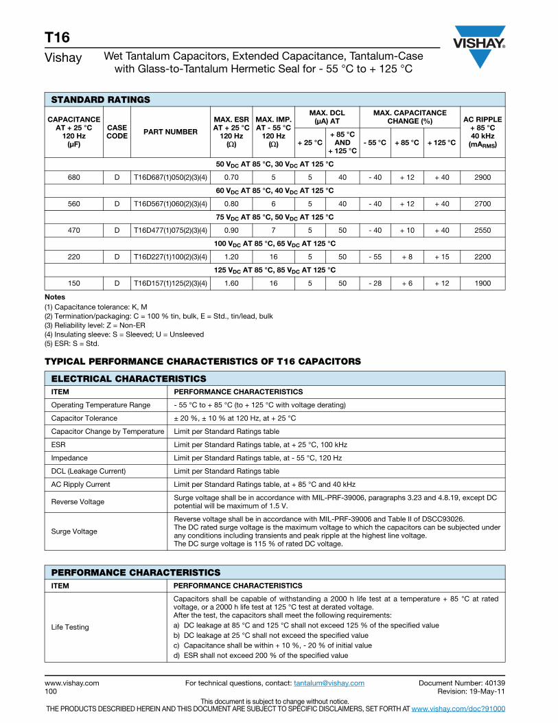
www.vishay.com For technical questions, contact: [email protected] Document Number: 40139100 Revision: 19-May-11
This document is subject to change without notice. THE PRODUCTS DESCRIBED HEREIN AND THIS DOCUMENT ARE SUBJECT TO SPECIFIC DISCLAIMERS, SET FORTH AT www.vishay.com/doc?91000
T16Vishay Wet Tantalum Capacitors, Extended Capacitance, Tantalum-Case
with Glass-to-Tantalum Hermetic Seal for - 55 °C to + 125 °C
Notes(1) Capacitance tolerance: K, M(2) Termination/packaging: C = 100 % tin, bulk, E = Std., tin/lead, bulk(3) Reliability level: Z = Non-ER(4) Insulating sleeve: S = Sleeved; U = Unsleeved(5) ESR: S = Std.
TYPICAL PERFORMANCE CHARACTERISTICS OF T16 CAPACITORS
STANDARD RATINGS
CAPACITANCE AT + 25 °C
120 Hz(μF)
CASE CODE PART NUMBER
MAX. ESRAT + 25 °C
120 Hz()
MAX. IMP.AT - 55 °C
120 Hz()
MAX. DCL (μA) AT
MAX. CAPACITANCECHANGE (%) AC RIPPLE
+ 85 °C40 kHz
(mARMS)+ 25 °C+ 85 °C
AND + 125 °C
- 55 °C + 85 °C + 125 °C
50 VDC AT 85 °C, 30 VDC AT 125 °C
680 D T16D687(1)050(2)(3)(4) 0.70 5 5 40 - 40 + 12 + 40 2900
60 VDC AT 85 °C, 40 VDC AT 125 °C
560 D T16D567(1)060(2)(3)(4) 0.80 6 5 40 - 40 + 12 + 40 2700
75 VDC AT 85 °C, 50 VDC AT 125 °C
470 D T16D477(1)075(2)(3)(4) 0.90 7 5 50 - 40 + 10 + 40 2550
100 VDC AT 85 °C, 65 VDC AT 125 °C
220 D T16D227(1)100(2)(3)(4) 1.20 16 5 50 - 55 + 8 + 15 2200
125 VDC AT 85 °C, 85 VDC AT 125 °C
150 D T16D157(1)125(2)(3)(4) 1.60 16 5 50 - 28 + 6 + 12 1900
ELECTRICAL CHARACTERISTICSITEM PERFORMANCE CHARACTERISTICS
Operating Temperature Range - 55 °C to + 85 °C (to + 125 °C with voltage derating)
Capacitor Tolerance ± 20 %, ± 10 % at 120 Hz, at + 25 °C
Capacitor Change by Temperature Limit per Standard Ratings table
ESR Limit per Standard Ratings table, at + 25 °C, 100 kHz
Impedance Limit per Standard Ratings table, at - 55 °C, 120 Hz
DCL (Leakage Current) Limit per Standard Ratings table
AC Ripply Current Limit per Standard Ratings table, at + 85 °C and 40 kHz
Reverse Voltage Surge voltage shall be in accordance with MIL-PRF-39006, paragraphs 3.23 and 4.8.19, except DC potential will be maximum of 1.5 V.
Surge Voltage
Reverse voltage shall be in accordance with MIL-PRF-39006 and Table II of DSCC93026.The DC rated surge voltage is the maximum voltage to which the capacitors can be subjected under any conditions including transients and peak ripple at the highest line voltage.The DC surge voltage is 115 % of rated DC voltage.
PERFORMANCE CHARACTERISTICSITEM PERFORMANCE CHARACTERISTICS
Life Testing
Capacitors shall be capable of withstanding a 2000 h life test at a temperature + 85 °C at ratedvoltage, or a 2000 h life test at 125 °C test at derated voltage.After the test, the capacitors shall meet the following requirements:a) DC leakage at 85 °C and 125 °C shall not exceed 125 % of the specified valueb) DC leakage at 25 °C shall not exceed the specified valuec) Capacitance shall be within + 10 %, - 20 % of initial valued) ESR shall not exceed 200 % of the specified value
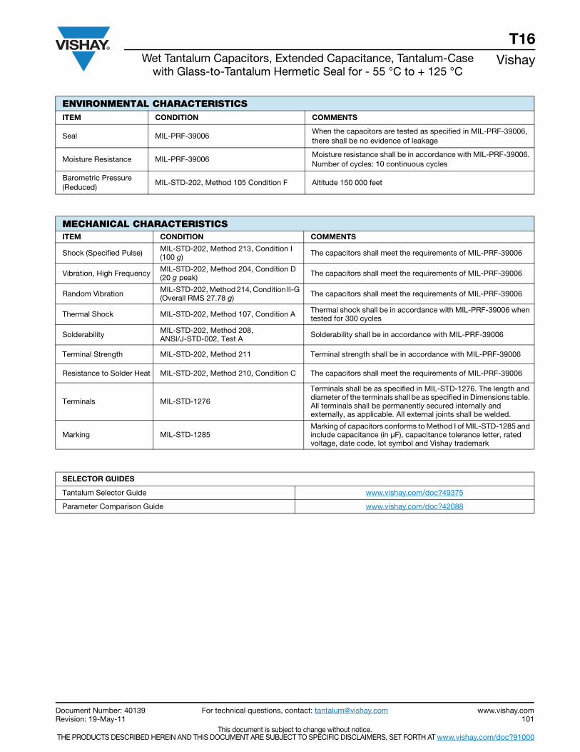
Document Number: 40139 For technical questions, contact: [email protected] www.vishay.comRevision: 19-May-11 101
This document is subject to change without notice. THE PRODUCTS DESCRIBED HEREIN AND THIS DOCUMENT ARE SUBJECT TO SPECIFIC DISCLAIMERS, SET FORTH AT www.vishay.com/doc?91000
T16Wet Tantalum Capacitors, Extended Capacitance, Tantalum-Case
with Glass-to-Tantalum Hermetic Seal for - 55 °C to + 125 °CVishay
ENVIRONMENTAL CHARACTERISTICSITEM CONDITION COMMENTS
Seal MIL-PRF-39006When the capacitors are tested as specified in MIL-PRF-39006, there shall be no evidence of leakage
Moisture Resistance MIL-PRF-39006Moisture resistance shall be in accordance with MIL-PRF-39006. Number of cycles: 10 continuous cycles
Barometric Pressure (Reduced)
MIL-STD-202, Method 105 Condition F Altitude 150 000 feet
MECHANICAL CHARACTERISTICSITEM CONDITION COMMENTS
Shock (Specified Pulse) MIL-STD-202, Method 213, Condition I(100 g) The capacitors shall meet the requirements of MIL-PRF-39006
Vibration, High Frequency MIL-STD-202, Method 204, Condition D (20 g peak) The capacitors shall meet the requirements of MIL-PRF-39006
Random Vibration MIL-STD-202, Method 214, Condition II-G (Overall RMS 27.78 g) The capacitors shall meet the requirements of MIL-PRF-39006
Thermal Shock MIL-STD-202, Method 107, Condition A Thermal shock shall be in accordance with MIL-PRF-39006 when tested for 300 cycles
Solderability MIL-STD-202, Method 208, ANSI/J-STD-002, Test A Solderability shall be in accordance with MIL-PRF-39006
Terminal Strength MIL-STD-202, Method 211 Terminal strength shall be in accordance with MIL-PRF-39006
Resistance to Solder Heat MIL-STD-202, Method 210, Condition C The capacitors shall meet the requirements of MIL-PRF-39006
Terminals MIL-STD-1276
Terminals shall be as specified in MIL-STD-1276. The length and diameter of the terminals shall be as specified in Dimensions table. All terminals shall be permanently secured internally and externally, as applicable. All external joints shall be welded.
Marking MIL-STD-1285Marking of capacitors conforms to Method I of MIL-STD-1285 and include capacitance (in μF), capacitance tolerance letter, rated voltage, date code, lot symbol and Vishay trademark
SELECTOR GUIDES
Tantalum Selector Guide www.vishay.com/doc?49375
Parameter Comparison Guide www.vishay.com/doc?42088
Contents
134D ............................... 96
135D ............................... 37
138D ............................... 19
XTH-K-L-M-V ................. 103High
Temperature
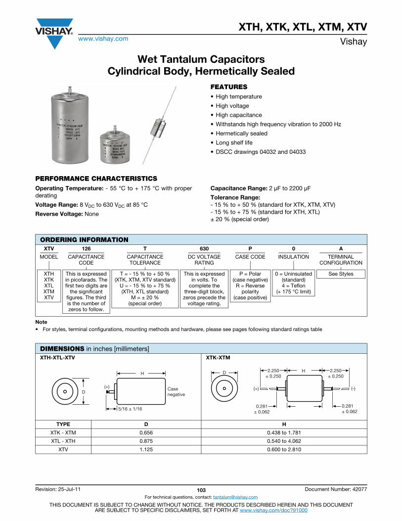
XTH, XTK, XTL, XTM, XTVwww.vishay.com Vishay
Revision: 25-Jul-11 103 Document Number: 42077
For technical questions, contact: [email protected]
THIS DOCUMENT IS SUBJECT TO CHANGE WITHOUT NOTICE. THE PRODUCTS DESCRIBED HEREIN AND THIS DOCUMENTARE SUBJECT TO SPECIFIC DISCLAIMERS, SET FORTH AT www.vishay.com/doc?91000
Wet Tantalum CapacitorsCylindrical Body, Hermetically Sealed
FEATURES• High temperature
• High voltage
• High capacitance
• Withstands high frequency vibration to 2000 Hz
• Hermetically sealed
• Long shelf life
• DSCC drawings 04032 and 04033
PERFORMANCE CHARACTERISTICSOperating Temperature: - 55 °C to + 175 °C with properderating
Voltage Range: 8 VDC to 630 VDC at 85 °C
Reverse Voltage: None
Capacitance Range: 2 μF to 2200 μF
Tolerance Range:- 15 % to + 50 % (standard for XTK, XTM, XTV)- 15 % to + 75 % (standard for XTH, XTL)± 20 % (special order)
Note• For styles, terminal configurations, mounting methods and hardware, please see pages following standard ratings table
ORDERING INFORMATIONXTV 126 T 630 P 0 A
MODEL CAPACITANCECODE
CAPACITANCETOLERANCE
DC VOLTAGERATING
CASE CODE INSULATION TERMINALCONFIGURATION
XTHXTKXTLXTMXTV
This is expressedin picofarads. Thefirst two digits are
the significantfigures. The thirdis the number ofzeros to follow.
T = - 15 % to + 50 %(XTK, XTM, XTV standard)
U = - 15 % to + 75 %(XTH, XTL standard)
M = ± 20 %(special order)
This is expressedin volts. To
complete thethree-digit block,zeros precede the
voltage rating.
P = Polar(case negative)
R = Reversepolarity
(case positive)
0 = Uninsulated(standard)4 = Teflon
(+ 175 °C limit)
See Styles
DIMENSIONS in inches [millimeters]XTH-XTL-XTV XTK-XTM
TYPE D H
XTK - XTM 0.656 0.438 to 1.781
XTL - XTH 0.875 0.540 to 4.062
XTV 1.125 0.600 to 2.810
H
5/16 ± 1/16
(+)D
Casenegative
H
(+)
D
0.281± 0.062
2.250± 0.250
2.250± 0.250
0.281± 0.062
(-)

XTH, XTK, XTL, XTM, XTVwww.vishay.com Vishay
Revision: 25-Jul-11 104 Document Number: 42077
For technical questions, contact: [email protected]
THIS DOCUMENT IS SUBJECT TO CHANGE WITHOUT NOTICE. THE PRODUCTS DESCRIBED HEREIN AND THIS DOCUMENTARE SUBJECT TO SPECIFIC DISCLAIMERS, SET FORTH AT www.vishay.com/doc?91000
STANDARD RATINGS AND DIMENSIONS
CAPACITANCE MAX.WORKINGVOLTAGE
TYP.ESR
MAX. DCL ATMAX. VDC
(μA)
MAX.Z
- 55 °C
MAX. % CAP.CHANGE FROMROOM TEMP.
APPROX.WEIGHT
MAX.RIPPLE 120 Hz RMS
- 55 °CTO
+ 175 °C
SIZE
PART NUMBER
D + 0.031 - 0.015
H + 0.062- 0.062
(μF) + 125 °C + 175 °C () + 85 °C + 125 °C + 175 °C () - 55 °C + 85 °C + 175 °C (g) (mA)
8 VDC AT + 85 °C
70 7 5 10.0 30 45 60 60 - 60 + 30 + 30 14 137 0.656 0.438 XTK706(1)008P0A
140 7 5 5.0 50 75 100 30 - 60 + 30 + 30 15 213 0.656 0.562 XTM147(1)008P0A
10 VDC AT + 85 °C
50 8.5 7 10.0 25 37 50 75 - 60 + 30 + 30 14 137 0.656 0.438 XTK506(1)010P0A
100 8.5 7 5.0 45 67 90 40 - 60 + 30 + 30 15 213 0.656 0.562 XTM107(1)010P0A
12 VDC AT + 85 °C
580 10 8 1.5 135 197 270 20 - 90 + 20 + 35 48 550 1.125 0.600 XTV587(1)012P0A
850 10 8 1.5 135 197 270 20 - 90 + 20 + 35 50 550 1.125 0.600 XTV857(1)012P0A
1100 10 8 1.5 135 197 270 20 - 90 + 20 + 35 60 694 1.125 1.100 XTV118(1)012P0A
2200 10 8 1.5 135 197 270 20 - 90 + 20 + 35 82 694 1.125 1.100 XTV228(1)012P0A
18 VDC AT + 85 °C
35 15 12 10.0 30 45 60 85 - 60 + 30 + 30 14 137 0.656 0.438 XTK356(1)018P0A
70 15 12 5.0 50 75 100 45 - 60 + 30 + 30 15 213 0.656 0.562 XTM706(1)018P0A
120 15 12 2.8 50 75 100 30 - 60 + 15 + 40 26 328 0.875 0.540 XTL127(1)018P0A
240 15 12 2.5 80 120 160 20 - 60 + 15 + 40 32 390 0.875 0.732 XTH247(1)018P0A
390 15 12 1.5 165 227 330 20 - 85 + 20 + 35 48 550 1.125 0.600 XTV397(1)018P0A
560 15 12 1.5 165 227 330 20 - 85 + 20 + 35 50 550 1.125 0.600 XTV567(1)018P0A
900 15 12 1.5 165 227 330 20 - 85 + 20 + 35 68 694 1.125 1.100 XTV907(1)018P0A
1800 15 12 1.5 165 227 330 20 - 85 + 20 + 35 82 694 1.125 1.100 XTV188(1)018P0A
20 VDC AT + 85 °C
28 17.5 13 10.0 30 45 60 85 - 60 + 30 + 30 14 137 0.656 0.438 XTK286(1)020P0A
56 17.5 13 5.0 50 75 100 45 - 60 + 30 + 30 15 213 0.656 0.562 XTM566(1)020P0A
100 17.5 13 2.8 50 75 100 30 - 60 + 15 + 40 26 328 0.875 0.540 XTL107(1)020P0A
200 17.5 13 2.5 80 120 160 20 - 60 + 15 + 40 32 390 0.875 0.732 XTH207(1)020P0A
30 VDC AT + 85 °C
20 25 20 10.0 35 52 70 125 - 40 + 20 + 20 14 137 0.656 0.438 XTK206(1)030P0A
40 25 20 5.0 60 90 120 75 - 40 + 20 + 20 15 213 0.656 0.562 XTM406(1)030P0A
75 25 20 2.7 55 82 110 45 - 45 + 15 + 30 26 333 0.875 0.540 XTL756(1)030P0A
150 25 20 2.7 90 135 180 30 - 45 + 15 + 30 32 375 0.875 0.732 XTH157(1)030P0A
250 25 20 2.5 195 287 390 20 - 65 + 20 + 35 48 427 1.125 0.600 XTV257(1)030P0A
370 25 20 1.5 125 170 215 15 - 65 + 20 + 35 50 550 1.125 0.600 XTV377(1)030P0A
650 25 20 1.5 145 202 250 15 - 85 + 20 + 35 68 694 1.125 1.100 XTV657(1)030P0A
1300 25 20 1.5 190 282 375 10 - 85 + 20 + 35 82 694 1.125 1.100 XTV138(1)030P0A
35 VDC AT + 85 °C
20 30 23 10.0 35 52 72 125 - 40 + 20 + 20 14 137 0.656 0.438 XTK206(1)035P0A
40 30 23 5.0 60 90 120 75 - 40 + 20 + 20 15 213 0.656 0.562 XTM406(1)035P0A
60 30 23 2.7 55 82 110 45 - 45 + 10 + 30 26 333 0.875 0.540 XTL606(1)035P0A
Note• Part number definitions:
(1) Tolerance code:T = - 15 % to + 50 % (standard for XTK, XTM, XTV)U = -15 % to + 75 % (standard for XTH, XTL)M = ± 20 % (available by special order)
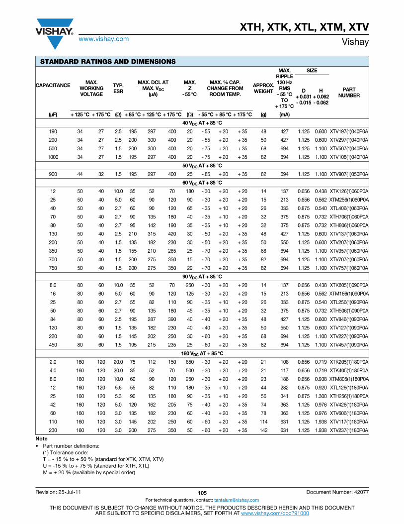
XTH, XTK, XTL, XTM, XTVwww.vishay.com Vishay
Revision: 25-Jul-11 105 Document Number: 42077
For technical questions, contact: [email protected]
THIS DOCUMENT IS SUBJECT TO CHANGE WITHOUT NOTICE. THE PRODUCTS DESCRIBED HEREIN AND THIS DOCUMENTARE SUBJECT TO SPECIFIC DISCLAIMERS, SET FORTH AT www.vishay.com/doc?91000
40 VDC AT + 85 °C
190 34 27 2.5 195 297 400 20 - 55 + 20 + 35 48 427 1.125 0.600 XTV197(1)040P0A
290 34 27 2.5 200 300 400 20 - 55 + 20 + 35 50 427 1.125 0.600 XTV297(1)040P0A
500 34 27 1.5 200 300 400 20 - 75 + 20 + 35 68 694 1.125 1.100 XTV507(1)040P0A
1000 34 27 1.5 195 297 400 20 - 75 + 20 + 35 82 694 1.125 1.100 XTV108(1)040P0A
50 VDC AT + 85 °C
900 44 32 1.5 195 297 400 25 - 85 + 20 + 35 82 694 1.125 1.100 XTV907(1)050P0A
60 VDC AT + 85 °C
12 50 40 10.0 35 52 70 180 - 30 + 20 + 20 14 137 0.656 0.438 XTK126(1)060P0A
25 50 40 5.0 60 90 120 90 - 30 + 20 + 20 15 213 0.656 0.562 XTM256(1)060P0A
40 50 40 2.7 60 90 120 65 - 35 + 10 + 20 26 333 0.875 0.540 XTL406(1)060P0A
70 50 40 2.7 90 135 180 40 - 35 + 10 + 20 32 375 0.875 0.732 XTH706(1)060P0A
80 50 40 2.7 95 142 190 35 - 35 + 10 + 20 32 375 0.875 0.732 XTH806(1)060P0A
130 50 40 2.5 210 315 420 30 - 50 + 20 + 35 48 427 1.125 0.600 XTV137(1)060P0A
200 50 40 1.5 135 182 230 30 - 50 + 20 + 35 50 550 1.125 0.600 XTV207(1)060P0A
350 50 40 1.5 155 210 265 25 - 70 + 20 + 35 68 694 1.125 1.100 XTV357(1)060P0A
700 50 40 1.5 200 275 350 15 - 70 + 20 + 35 82 694 1.125 1.100 XTV707(1)060P0A
750 50 40 1.5 200 275 350 29 - 70 + 20 + 35 82 694 1.125 1.100 XTV757(1)060P0A
90 VDC AT + 85 °C
8.0 80 60 10.0 35 52 70 250 - 30 + 20 + 20 14 137 0.656 0.438 XTK805(1)090P0A
16 80 60 5.0 60 90 120 125 - 30 + 20 + 20 15 213 0.656 0.562 XTM166(1)090P0A
25 80 60 2.7 55 82 110 90 - 35 + 10 + 20 26 333 0.875 0.540 XTL256(1)090P0A
50 80 60 2.7 90 135 180 45 - 35 + 10 + 20 32 375 0.875 0.732 XTH506(1)090P0A
84 80 60 2.5 195 287 390 40 - 40 + 20 + 35 48 427 1.125 0.600 XTV846(1)090P0A
120 80 60 1.5 135 182 230 40 - 40 + 20 + 35 50 550 1.125 0.600 XTV127(1)090P0A
220 80 60 1.5 145 202 250 30 - 60 + 20 + 35 68 694 1.125 1.100 XTV227(1)090P0A
450 80 60 1.5 195 215 235 25 - 60 + 20 + 35 82 694 1.125 1.100 XTV457(1)090P0A
180 VDC AT + 85 °C
2.0 160 120 20.0 75 112 150 850 - 30 + 20 + 20 21 108 0.656 0.719 XTK205(1)180P0A
4.0 160 120 20.0 35 52 70 500 - 30 + 20 + 20 21 117 0.656 0.719 XTK405(1)180P0A
8.0 160 120 10.0 60 90 120 250 - 30 + 20 + 20 23 186 0.656 0.938 XTM805(1)180P0A
12 160 120 5.6 55 82 110 180 - 35 + 10 + 20 44 282 0.875 0.920 XTL126(1)180P0A
25 160 120 5.3 90 135 180 90 - 35 + 10 + 20 56 341 0.875 1.300 XTH256(1)180P0A
42 160 120 5.0 120 162 205 75 - 40 + 20 + 35 74 363 1.125 0.976 XTV426(1)180P0A
60 160 120 3.0 135 182 230 60 - 40 + 20 + 35 78 363 1.125 0.976 XTV606(1)180P0A
110 160 120 3.0 145 202 250 60 - 60 + 20 + 35 114 631 1.125 1.938 XTV117(1)180P0A
230 160 120 3.0 200 275 350 50 - 60 + 20 + 35 142 631 1.125 1.938 XTV237(1)180P0A
STANDARD RATINGS AND DIMENSIONS
CAPACITANCE MAX.WORKINGVOLTAGE
TYP.ESR
MAX. DCL ATMAX. VDC
(μA)
MAX.Z
- 55 °C
MAX. % CAP.CHANGE FROMROOM TEMP.
APPROX.WEIGHT
MAX.RIPPLE 120 Hz RMS
- 55 °CTO
+ 175 °C
SIZE
PART NUMBER
D + 0.031 - 0.015
H + 0.062- 0.062
(μF) + 125 °C + 175 °C () + 85 °C + 125 °C + 175 °C () - 55 °C + 85 °C + 175 °C (g) (mA)
Note• Part number definitions:
(1) Tolerance code:T = - 15 % to + 50 % (standard for XTK, XTM, XTV)U = -15 % to + 75 % (standard for XTH, XTL)M = ± 20 % (available by special order)
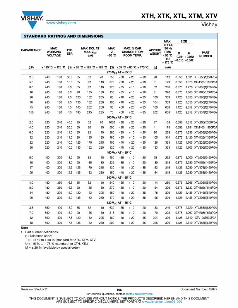
XTH, XTK, XTL, XTM, XTVwww.vishay.com Vishay
Revision: 25-Jul-11 106 Document Number: 42077
For technical questions, contact: [email protected]
THIS DOCUMENT IS SUBJECT TO CHANGE WITHOUT NOTICE. THE PRODUCTS DESCRIBED HEREIN AND THIS DOCUMENTARE SUBJECT TO SPECIFIC DISCLAIMERS, SET FORTH AT www.vishay.com/doc?91000
270 VDC AT + 85 °C
2.5 240 180 30.0 35 52 70 750 - 30 + 20 + 20 28 112 0.656 1.031 XTK255(1)270P0A
5.0 240 180 15.0 55 82 110 375 - 30 + 20 + 20 31 179 0.656 1.375 XTM505(1)270P0A
8.0 240 180 8.3 55 82 110 270 - 35 + 10 + 20 62 266 0.875 1.270 XTL805(1)270P0A
16 240 180 8.3 90 135 180 135 - 35 + 10 + 20 81 320 0.875 1.865 XTH166(1)270P0A
28 240 180 7.5 120 162 205 80 - 40 + 20 + 35 100 339 1.125 1.350 XTV286(1)270P0A
40 240 180 7.5 135 182 230 100 - 40 + 20 + 35 104 339 1.125 1.350 XTV406(1)270P0A
75 240 180 4.5 145 202 250 90 - 60 + 20 + 35 160 608 1.125 2.812 XTV756(1)270P0A
150 240 180 4.5 195 215 235 75 - 60 + 20 + 35 202 608 1.125 2.812 XTV157(1)270P0A
360 VDC AT + 85 °C
2.0 320 240 40.0 35 52 70 1000 - 30 + 20 + 20 37 108 0.656 1.312 XTK205(1)360P0A
4.0 320 240 20.0 60 90 120 500 - 30 + 20 + 20 41 175 0.656 1.781 XTM405(1)360P0A
6.0 320 240 11.0 55 82 110 360 - 35 + 10 + 20 80 258 0.875 1.635 XTL605(1)360P0A
12 320 240 11.0 90 135 180 180 - 35 + 10 + 20 105 314 0.875 2.420 XTH126(1)360P0A
22 320 240 10.0 125 170 215 100 - 40 + 20 + 35 126 323 1.125 1.705 XTV226(1)360P0A
30 320 240 10.0 135 182 230 120 - 40 + 20 + 35 133 323 1.125 1.705 XTV306(1)360P0A
450 VDC AT + 85 °C
5.0 400 300 13.0 55 82 110 450 - 35 + 10 + 20 98 262 0.875 2.000 XTL505(1)450P0A
10 400 300 13.0 90 135 180 225 - 35 + 10 + 20 130 318 0.875 2.980 XTH106(1)450P0A
17 400 300 12.5 125 170 215 130 - 40 + 20 + 35 152 315 1.125 2.080 XTV176(1)450P0A
25 400 300 12.5 135 182 230 150 - 40 + 20 + 35 164 315 1.125 2.080 XTV256(1)450P0A
540 VDC AT + 85 °C
4.0 480 360 16.6 55 82 110 540 - 35 + 10 + 20 114 250 0.875 2.365 XTL405(1)540P0A
8.0 480 360 16.6 90 135 180 270 - 35 + 10 + 20 154 306 0.875 3.532 XTH805(1)540P0A
14 480 300 15.0 120 162 205 160 - 40 + 20 + 35 178 309 1.125 2.435 XTV146(1)540P0A
20 480 300 15.0 135 182 230 170 - 40 + 20 + 35 196 309 1.125 2.435 XTV206(1)540P0A
630 VDC AT + 85 °C
3.5 560 420 18.9 55 82 110 630 - 35 + 10 + 20 133 249 0.875 2.720 XTL355(1)630P0A
7.0 560 420 18.9 90 135 180 315 - 35 + 10 + 20 179 308 0.875 4.062 XTH705(1)630P0A
12 560 420 17.5 120 162 205 180 - 40 + 20 + 35 204 306 1.125 2.810 XTV126T630P0A
18 560 420 17.5 135 182 230 200 - 40 + 20 + 35 225 306 1.125 2.810 XTV186(1)630P0A
STANDARD RATINGS AND DIMENSIONS
CAPACITANCE MAX.WORKINGVOLTAGE
TYP.ESR
MAX. DCL ATMAX. VDC
(μA)
MAX.Z
- 55 °C
MAX. % CAP.CHANGE FROMROOM TEMP.
APPROX.WEIGHT
MAX.RIPPLE 120 Hz RMS
- 55 °CTO
+ 175 °C
SIZE
PART NUMBER
D + 0.031 - 0.015
H + 0.062- 0.062
(μF) + 125 °C + 175 °C () + 85 °C + 125 °C + 175 °C () - 55 °C + 85 °C + 175 °C (g) (mA)
Note• Part number definitions:
(1) Tolerance code:T = - 15 % to + 50 % (standard for XTK, XTM, XTV)U = -15 % to + 75 % (standard for XTH, XTL)M = ± 20 % (available by special order)

XTH, XTK, XTL, XTM, XTVwww.vishay.com Vishay
Revision: 25-Jul-11 107 Document Number: 42077
For technical questions, contact: [email protected]
THIS DOCUMENT IS SUBJECT TO CHANGE WITHOUT NOTICE. THE PRODUCTS DESCRIBED HEREIN AND THIS DOCUMENTARE SUBJECT TO SPECIFIC DISCLAIMERS, SET FORTH AT www.vishay.com/doc?91000
XTH-L-V STYLESSTYLE A STYLE B STYLE C
STYLE D STYLE E STYLE F
STYLE G STYLE H STYLE J
STYLE K STYLE L STYLE M
H
0.3125 ± 0.0625
(+)
Top Bottom
D
0.3125± 0.0625
0.375± 0.0625
(+)
0.4375DIA.
0.250NOM.
BottomTop
0.3125 ± 0.0625
(+)
BottomTop
0.4063± 0.0625
0.183± 0.010
Wire hole0.094 ± 0.010
0.025± 0.005
0.3125 ± 0.0625
(+)
BottomTop
Negative screw lug is for indexing andnegative connection only
0.500 ± 0.06250.047
8-32UNC-2Athread 0.3125 ± 0.0625
(+)
Top Bottom
0.5625 ± 0.0625
0.065 MAX.
1/4-20UNC-3Athread
0.500± 0.0625DIA.
See Detail C in Mounting Methods tablefor suggested mounting methods
(+)
Top Bottom
0.385 MAX.0.075 MAX.
8-32UNC-2Athread
See Detail D in Mounting Methods tablefor suggested mounting method
0.3125 ± 0.0625
0.500DIA.MAX.
(+)
Top Bottom
0.500 ± 0.0625
0.047
Negative screw lug is forindex and negativeconnection only
Wire hole0.094 ± 0.010
0.3125 ± 0.0625
0.4063± 0.0625
0.025± 0.005
0.183± 0.010
8-32UNC-2Athread
0.3125± 0.0625
(+)
0.5625 ± 0.0625
0.075 MAX.
1/4-20UNC-3Athread
0.500± 0.0625DIA.
0.183± 0.010
0.025± 0.005
0.4063± 0.0625
See Detail C in MountingMethods table for suggested
mounting methods
Wire hole0.094 ± 0.010
Top Bottom
0.3125± 0.0625
(+)
0.385 MAX.0.075 MAX.
0.183± 0.010
0.025± 0.005
0.4063± 0.0625
See Detail D in MountingMethods table for suggested
mounting methods
8-32UNC-2Athread
Wire hole0.094 ± 0.010
0.500DIA.MAX.
Top Bottom
Top
Bottom0.500± 0.010
0.375 + 0.007- 0.005
1/2-20UNF-2A THREAD
0.030 ± 0.020 XTH-XTL0.060 ± 0.020 XTV
0.375± 0.015
(+)
See Details B and E in Mounting Methods tablefor suggested mounting methods
Top
Bottom0.500± 0.010
0.030 ± 0.020 XTH-XTL0.060 ± 0.020 XTV
(+)
0.590± 0.015
0.025± 0.015
See Detail B and E in Mounting Methods tablefor suggested mounting methods
1/2-20UNF-2A THREAD
0.375± 0.015
0.375 + 0.007- 0.005
0.3125 ± 0.0625
(+)
0.060MAX.
0.125 MAX.
* Extends 0.125 on 0.875 DIA. units only
Top Bottom

XTH, XTK, XTL, XTM, XTVwww.vishay.com Vishay
Revision: 25-Jul-11 108 Document Number: 42077
For technical questions, contact: [email protected]
THIS DOCUMENT IS SUBJECT TO CHANGE WITHOUT NOTICE. THE PRODUCTS DESCRIBED HEREIN AND THIS DOCUMENTARE SUBJECT TO SPECIFIC DISCLAIMERS, SET FORTH AT www.vishay.com/doc?91000
XTK-M STYLESSTYLE A STYLE B STYLE C STYLE D
STYLE E STYLE F STYLE G STYLE H
POSITIVE TERMINALS FOR XTK AND XTMSTYLE A STYLE B, C AND D STYLE E, G AND H STYLE F
NEGATIVE TERMINALS FOR XTK AND XTMSTYLE A STYLE B, E AND F STYLE C AND G STYLE D AND H
POS NEG POS NEG POS NEG POS NEG
POS NEG POS NEG POS NEG POS NEG
0.035 DIA.
2.250± 0.025
H ± 0.062
0.281± 0.062
0.062
0.125
Terminal detailenlarged
0.125
0.500 ± 0.062 0.432± 0.05
0.285MAX.
0.812± 0.062 0.555
± 0.015
3/8-24 UNF 2Athread
H ± 0.062 0.020± 0.015
0.432± 0.05
0.285MAX.
0.812± 0.062 0.555
± 0.015
3/8-24 UNF 2Athread
H ± 0.0620.020± 0.015
0.100 MAX.
0.750± 0.020
0.281± 0.062 2.250
± 0.025
0.656± 0.025
0.035 DIA.
0.656± 0.025
Case negative0.078 DIA.
hole
0.656± 0.025
0.375± 0.062
0.187
6-32NC 2Athread
0.656± 0.025
0.375± 0.062
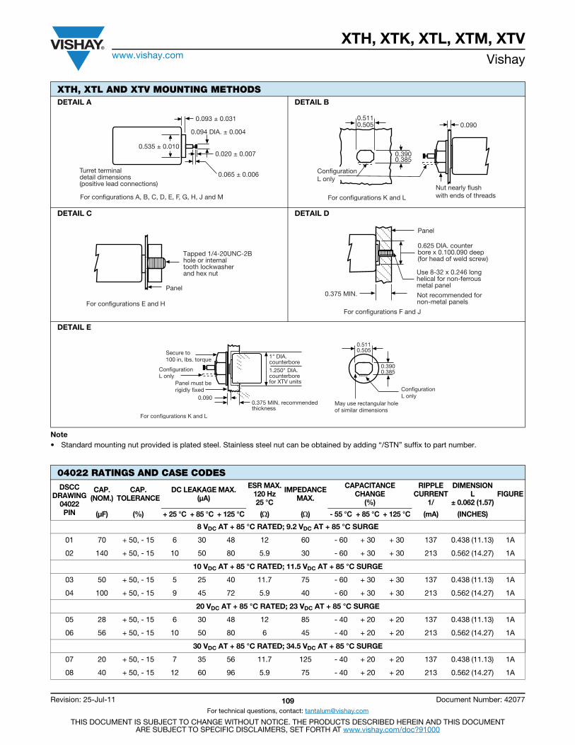
XTH, XTK, XTL, XTM, XTVwww.vishay.com Vishay
Revision: 25-Jul-11 109 Document Number: 42077
For technical questions, contact: [email protected]
THIS DOCUMENT IS SUBJECT TO CHANGE WITHOUT NOTICE. THE PRODUCTS DESCRIBED HEREIN AND THIS DOCUMENTARE SUBJECT TO SPECIFIC DISCLAIMERS, SET FORTH AT www.vishay.com/doc?91000
Note• Standard mounting nut provided is plated steel. Stainless steel nut can be obtained by adding “/STN” suffix to part number.
XTH, XTL AND XTV MOUNTING METHODSDETAIL A DETAIL B
DETAIL C DETAIL D
DETAIL E
04022 RATINGS AND CASE CODESDSCC
DRAWING04022PIN
CAP.(NOM.)
CAP.TOLERANCE
DC LEAKAGE MAX.(μA)
ESR MAX.120 Hz25 °C
IMPEDANCEMAX.
CAPACITANCECHANGE
(%)
RIPPLECURRENT
1/
DIMENSIONL
± 0.062 (1.57)FIGURE
(μF) (%) + 25 °C + 85 °C + 125 °C () () - 55 °C + 85 °C + 125 °C (mA) (INCHES)
8 VDC AT + 85 °C RATED; 9.2 VDC AT + 85 °C SURGE
01 70 + 50, - 15 6 30 48 12 60 - 60 + 30 + 30 137 0.438 (11.13) 1A
02 140 + 50, - 15 10 50 80 5.9 30 - 60 + 30 + 30 213 0.562 (14.27) 1A
10 VDC AT + 85 °C RATED; 11.5 VDC AT + 85 °C SURGE
03 50 + 50, - 15 5 25 40 11.7 75 - 60 + 30 + 30 137 0.438 (11.13) 1A
04 100 + 50, - 15 9 45 72 5.9 40 - 60 + 30 + 30 213 0.562 (14.27) 1A
20 VDC AT + 85 °C RATED; 23 VDC AT + 85 °C SURGE
05 28 + 50, - 15 6 30 48 12 85 - 40 + 20 + 20 137 0.438 (11.13) 1A
06 56 + 50, - 15 10 50 80 6 45 - 40 + 20 + 20 213 0.562 (14.27) 1A
30 VDC AT + 85 °C RATED; 34.5 VDC AT + 85 °C SURGE
07 20 + 50, - 15 7 35 56 11.7 125 - 40 + 20 + 20 137 0.438 (11.13) 1A
08 40 + 50, - 15 12 60 96 5.9 75 - 40 + 20 + 20 213 0.562 (14.27) 1A
0.065 ± 0.006
0.093 ± 0.031
Turret terminaldetail dimensions(positive lead connections)
0.094 DIA. ± 0.004
For configurations A, B, C, D, E, F, G, H, J and M
0.020 ± 0.0070.535 ± 0.010
ConfigurationL only
Nut nearly flushwith ends of threads
0.090
For configurations K and L
0.3900.385
0.5110.505
Tapped 1/4-20UNC-2Bhole or internaltooth lockwasherand hex nut
For configurations E and H
PanelNot recommended fornon-metal panels
For configurations F and J
Panel
Use 8-32 x 0.246 longhelical for non-ferrousmetal panel
0.625 DIA. counterbore x 0.100.090 deep(for head of weld screw)
0.375 MIN.
0.375 MIN. recommendedthickness
0.090
1" DIA.counterbore
1.250" DIA.counterborefor XTV units
ConfigurationL only
Secure to100 in, lbs. torque
Panel must berigidly fixed
For configurations K and L
May use rectangular holeof similar dimensions
0.3900.385
0.5110.505
ConfigurationL only
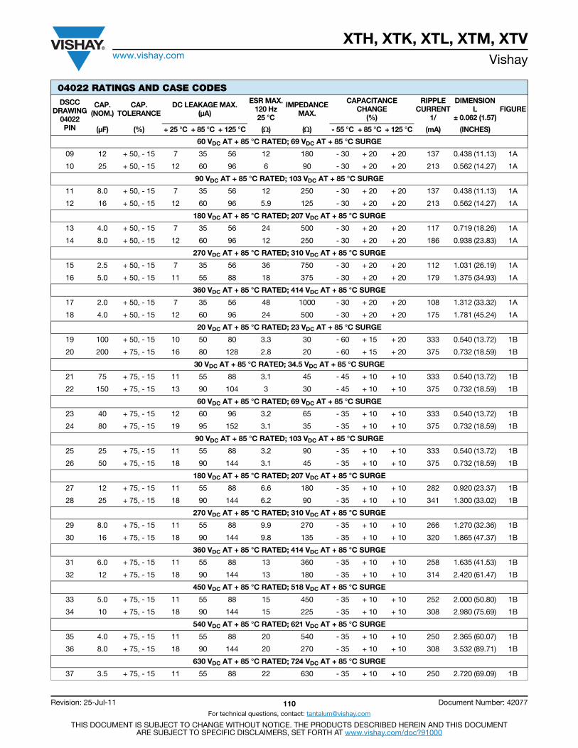
XTH, XTK, XTL, XTM, XTVwww.vishay.com Vishay
Revision: 25-Jul-11 110 Document Number: 42077
For technical questions, contact: [email protected]
THIS DOCUMENT IS SUBJECT TO CHANGE WITHOUT NOTICE. THE PRODUCTS DESCRIBED HEREIN AND THIS DOCUMENTARE SUBJECT TO SPECIFIC DISCLAIMERS, SET FORTH AT www.vishay.com/doc?91000
60 VDC AT + 85 °C RATED; 69 VDC AT + 85 °C SURGE
09 12 + 50, - 15 7 35 56 12 180 - 30 + 20 + 20 137 0.438 (11.13) 1A
10 25 + 50, - 15 12 60 96 6 90 - 30 + 20 + 20 213 0.562 (14.27) 1A
90 VDC AT + 85 °C RATED; 103 VDC AT + 85 °C SURGE
11 8.0 + 50, - 15 7 35 56 12 250 - 30 + 20 + 20 137 0.438 (11.13) 1A
12 16 + 50, - 15 12 60 96 5.9 125 - 30 + 20 + 20 213 0.562 (14.27) 1A
180 VDC AT + 85 °C RATED; 207 VDC AT + 85 °C SURGE
13 4.0 + 50, - 15 7 35 56 24 500 - 30 + 20 + 20 117 0.719 (18.26) 1A
14 8.0 + 50, - 15 12 60 96 12 250 - 30 + 20 + 20 186 0.938 (23.83) 1A
270 VDC AT + 85 °C RATED; 310 VDC AT + 85 °C SURGE
15 2.5 + 50, - 15 7 35 56 36 750 - 30 + 20 + 20 112 1.031 (26.19) 1A
16 5.0 + 50, - 15 11 55 88 18 375 - 30 + 20 + 20 179 1.375 (34.93) 1A
360 VDC AT + 85 °C RATED; 414 VDC AT + 85 °C SURGE
17 2.0 + 50, - 15 7 35 56 48 1000 - 30 + 20 + 20 108 1.312 (33.32) 1A
18 4.0 + 50, - 15 12 60 96 24 500 - 30 + 20 + 20 175 1.781 (45.24) 1A
20 VDC AT + 85 °C RATED; 23 VDC AT + 85 °C SURGE
19 100 + 50, - 15 10 50 80 3.3 30 - 60 + 15 + 20 333 0.540 (13.72) 1B
20 200 + 75, - 15 16 80 128 2.8 20 - 60 + 15 + 20 375 0.732 (18.59) 1B
30 VDC AT + 85 °C RATED; 34.5 VDC AT + 85 °C SURGE
21 75 + 75, - 15 11 55 88 3.1 45 - 45 + 10 + 10 333 0.540 (13.72) 1B
22 150 + 75, - 15 13 90 104 3 30 - 45 + 10 + 10 375 0.732 (18.59) 1B
60 VDC AT + 85 °C RATED; 69 VDC AT + 85 °C SURGE
23 40 + 75, - 15 12 60 96 3.2 65 - 35 + 10 + 10 333 0.540 (13.72) 1B
24 80 + 75, - 15 19 95 152 3.1 35 - 35 + 10 + 10 375 0.732 (18.59) 1B
90 VDC AT + 85 °C RATED; 103 VDC AT + 85 °C SURGE
25 25 + 75, - 15 11 55 88 3.2 90 - 35 + 10 + 10 333 0.540 (13.72) 1B
26 50 + 75, - 15 18 90 144 3.1 45 - 35 + 10 + 10 375 0.732 (18.59) 1B
180 VDC AT + 85 °C RATED; 207 VDC AT + 85 °C SURGE
27 12 + 75, - 15 11 55 88 6.6 180 - 35 + 10 + 10 282 0.920 (23.37) 1B
28 25 + 75, - 15 18 90 144 6.2 90 - 35 + 10 + 10 341 1.300 (33.02) 1B
270 VDC AT + 85 °C RATED; 310 VDC AT + 85 °C SURGE
29 8.0 + 75, - 15 11 55 88 9.9 270 - 35 + 10 + 10 266 1.270 (32.36) 1B
30 16 + 75, - 15 18 90 144 9.8 135 - 35 + 10 + 10 320 1.865 (47.37) 1B
360 VDC AT + 85 °C RATED; 414 VDC AT + 85 °C SURGE
31 6.0 + 75, - 15 11 55 88 13 360 - 35 + 10 + 10 258 1.635 (41.53) 1B
32 12 + 75, - 15 18 90 144 13 180 - 35 + 10 + 10 314 2.420 (61.47) 1B
450 VDC AT + 85 °C RATED; 518 VDC AT + 85 °C SURGE
33 5.0 + 75, - 15 11 55 88 15 450 - 35 + 10 + 10 252 2.000 (50.80) 1B
34 10 + 75, - 15 18 90 144 15 225 - 35 + 10 + 10 308 2.980 (75.69) 1B
540 VDC AT + 85 °C RATED; 621 VDC AT + 85 °C SURGE
35 4.0 + 75, - 15 11 55 88 20 540 - 35 + 10 + 10 250 2.365 (60.07) 1B
36 8.0 + 75, - 15 18 90 144 20 270 - 35 + 10 + 10 308 3.532 (89.71) 1B
630 VDC AT + 85 °C RATED; 724 VDC AT + 85 °C SURGE
37 3.5 + 75, - 15 11 55 88 22 630 - 35 + 10 + 10 250 2.720 (69.09) 1B
04022 RATINGS AND CASE CODESDSCC
DRAWING04022PIN
CAP.(NOM.)
CAP.TOLERANCE
DC LEAKAGE MAX.(μA)
ESR MAX.120 Hz25 °C
IMPEDANCEMAX.
CAPACITANCECHANGE
(%)
RIPPLECURRENT
1/
DIMENSIONL
± 0.062 (1.57)FIGURE
(μF) (%) + 25 °C + 85 °C + 125 °C () () - 55 °C + 85 °C + 125 °C (mA) (INCHES)
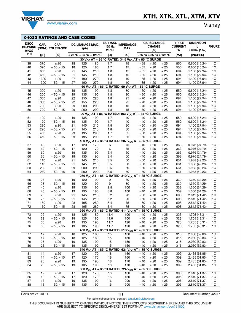
XTH, XTK, XTL, XTM, XTVwww.vishay.com Vishay
Revision: 25-Jul-11 111 Document Number: 42077
For technical questions, contact: [email protected]
THIS DOCUMENT IS SUBJECT TO CHANGE WITHOUT NOTICE. THE PRODUCTS DESCRIBED HEREIN AND THIS DOCUMENTARE SUBJECT TO SPECIFIC DISCLAIMERS, SET FORTH AT www.vishay.com/doc?91000
04022 RATINGS AND CASE CODESDSCC
DRAWING04022PIN
CAP.(NOM.)
CAP.TOLERANCE
DC LEAKAGE MAX.(μA)
ESR MAX.120 Hz25 °C
IMPEDANCEMAX.
CAPACITANCECHANGE
(%)
RIPPLECURRENT
1/
DIMENSIONL
± 0.062 (1.57)FIGURE
(μF) (%) + 25 °C + 85 °C + 125 °C () () - 55 °C + 85 °C + 125 °C (mA) (INCHES)30 VDC AT + 85 °C RATED; 34.5 VDC AT + 85 °C SURGE
39 370 ± 20 18 125 180 1.7 15 - 65 + 20 + 25 550 0.600 (15.24) 1C 40 370 + 50, - 15 18 125 180 1.7 15 - 65 + 20 + 25 550 0.600 (15.24) 1C 41 650 ± 20 21 145 210 1.8 15 - 85 + 20 + 25 694 1.100 (27.94) 1C 42 650 + 50, - 15 21 145 210 1.8 15 - 85 + 20 + 25 694 1.100 (27.94) 1C 43 1300 ± 20 27 190 270 1.8 10 - 85 + 20 + 25 694 1.100 (27.94) 1C 44 1300 + 50, - 15 27 190 270 1.8 10 - 85 + 20 + 25 694 1.100 (27.94) 1C
60 VDC AT + 85 °C RATED; 69 VDC AT + 85 °C SURGE45 200 ± 20 19 135 190 1.8 30 - 50 + 20 + 25 550 0.600 (15.24) 1C 46 200 + 50, - 15 19 135 190 1.8 30 - 50 + 20 + 25 550 0.600 (15.24) 1C 47 350 ± 20 22 155 220 1.8 25 - 70 + 20 + 25 694 1.100 (27.94) 1C 48 350 + 50, - 15 22 155 220 1.8 25 - 70 + 20 + 25 694 1.100 (27.94) 1C 49 700 ± 20 29 200 290 1.8 15 - 70 + 20 + 25 694 1.100 (27.94) 1C 50 700 + 50, - 15 29 200 290 1.8 15 - 70 + 20 + 25 694 1.100 (27.94) 1C
90 VDC AT + 85 °C RATED; 103 VDC AT + 85 °C SURGE51 120 ± 20 19 135 190 1.7 40 - 40 + 20 + 25 550 0.600 (15.24) 1C 52 120 + 50, - 15 19 135 190 1.7 40 - 40 + 20 + 25 550 0.600 (15.24) 1C 53 220 ± 20 21 145 210 1.8 30 - 60 + 20 + 25 694 1.100 (27.94) 1C 54 220 + 50, - 15 21 145 210 1.8 30 - 60 + 20 + 25 694 1.100 (27.94) 1C 55 450 ± 20 29 195 290 1.7 35 - 60 + 20 + 25 694 1.100 (27.94) 1C 56 450 + 50, - 15 29 195 290 1.7 35 - 60 + 20 + 25 694 1.100 (27.94) 1C
180 VDC AT + 85 °C RATED; 207 VDC AT + 85 °C SURGE 57 42 ± 20 17 120 170 6 75 - 40 + 20 + 25 363 0.976 (24.79) 1C 58 42 + 50, - 15 17 120 170 6 75 - 40 + 20 + 25 363 0.976 (24.79) 1C 59 60 ± 20 19 135 190 3.4 60 - 40 + 20 + 25 363 0.976 (24.79) 1C 60 60 + 50, - 15 19 135 190 3.4 60 - 40 + 20 + 25 363 0.976 (24.79) 1C 61 110 ± 20 21 145 210 3.5 60 - 60 + 20 + 25 631 1.938 (49.23) 1C 62 110 + 50, - 15 21 145 210 3.5 60 - 60 + 20 + 25 631 1.938 (49.23) 1C 63 230 ± 20 29 200 290 3.5 50 - 60 + 20 + 25 631 1.938 (49.23) 1C 64 230 + 50, - 15 29 200 290 3.5 50 - 60 + 20 + 25 631 1.938 (49.23) 1C
270 VDC AT + 85 °C RATED; 310 VDC AT + 85 °C SURGE 65 28 ± 20 19 120 190 9 80 - 40 + 20 + 25 339 1.350 (34.29) 1C 66 28 + 50, - 15 19 120 190 9 80 - 40 + 20 + 25 339 1.350 (34.29) 1C 67 40 ± 20 19 135 190 8.8 100 - 40 + 20 + 25 339 1.350 (34.29) 1C 68 40 + 50, - 15 19 135 190 8.8 100 - 40 + 20 + 25 339 1.350 (34.29) 1C 69 75 ± 20 21 145 210 5.2 90 - 60 + 20 + 25 608 2.812 (71.42) 1C 70 75 + 50, - 15 21 145 210 5.2 90 - 60 + 20 + 25 608 2.812 (71.42) 1C 71 150 ± 20 28 195 280 5.4 75 - 60 + 20 + 25 608 2.812 (71.42) 1C 72 150 + 50, - 15 28 195 280 5.4 75 - 60 + 20 + 25 608 2.812 (71.42) 1C
360 VDC AT + 85 °C RATED; 414 VDC AT + 85 °C SURGE 73 22 ± 20 18 125 180 11.4 100 - 40 + 20 + 25 323 1.705 (43.31) 1C 74 22 + 50, - 15 18 125 180 11.6 100 - 40 + 20 + 25 323 1.705 (43.31) 1C 75 30 ± 20 19 135 190 11.7 120 - 40 + 20 + 25 323 1.705 (43.31) 1C 76 30 + 50, - 15 19 135 190 11.7 120 - 40 + 20 + 25 323 1.705 (43.31) 1C
450 VDC AT + 85 °C RATED; 518 VDC AT + 85 °C SURGE 77 17 ± 20 18 125 180 15 130 - 40 + 20 + 25 315 2.080 (52.83) 1C 78 17 + 50, - 15 18 125 180 15 130 - 40 + 20 + 25 315 2.080 (52.83) 1C 79 25 ± 20 19 135 190 15 150 - 40 + 20 + 25 315 2.080 (52.83) 1C 80 25 + 50, - 15 19 135 190 15 150 - 40 + 20 + 25 315 2.080 (52.83) 1C
540 VDC AT + 85 °C RATED; 621 VDC AT + 85 °C SURGE 81 14 ± 20 17 120 170 18 160 - 40 + 20 + 25 309 2.435 (61.85) 1C 82 14 + 50, - 15 17 120 170 18 160 - 40 + 20 + 25 309 2.435 (61.85) 1C 83 20 ± 20 19 135 190 18 170 - 40 + 20 + 25 309 2.435 (61.85) 1C 84 20 + 50, - 15 19 135 190 18 170 - 40 + 20 + 25 309 2.435 (61.85) 1C
630 VDC AT + 85 °C RATED; 724 VDC AT + 85 °C SURGE85 12 ± 20 17 120 170 16 180 - 40 + 20 + 25 306 2.810 (71.37) 1C 86 12 + 50, - 15 17 120 170 16 180 - 40 + 20 + 25 306 2.810 (71.37) 1C 87 18 ± 20 19 135 190 16 200 - 40 + 20 + 25 306 2.810 (71.37) 1C 88 18 + 50, - 15 19 135 190 16 200 - 40 + 20 + 25 306 2.810 (71.37) 1C
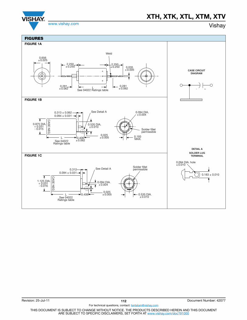
XTH, XTK, XTL, XTM, XTVwww.vishay.com Vishay
Revision: 25-Jul-11 112 Document Number: 42077
For technical questions, contact: [email protected]
THIS DOCUMENT IS SUBJECT TO CHANGE WITHOUT NOTICE. THE PRODUCTS DESCRIBED HEREIN AND THIS DOCUMENTARE SUBJECT TO SPECIFIC DISCLAIMERS, SET FORTH AT www.vishay.com/doc?91000
FIGURESFIGURE 1A
FIGURE 1B
FIGURE 1C
CASE CIRCUITDIAGRAM
- +
DETAIL A
SOLDER LUGTERMINAL
0.094 DIA. hole± 0.010
0.183 ± 0.010
Weld
0.281± 0.062
2.250± 0.250
0.281± 0.062
2.250± 0.250
0.656± 0.025
0.035± 0.005+
+
+
LSee 04022 Ratings table
0.313 ± 0.062
0.193MAX.
See Detail A
0.535 DIA.± 0.010
0.875 DIA.+ 0.031- 0.015
CA
SE
NE
G
0.094 ± 0.031
0.406± 0.062
LSee 04022
Ratings table
0.025± 0.005
0.094 DIA.± 0.004
Solder filletpermissible
0.312 See Detail A
0.094 DIA.± 0.004
1.125 DIA.+ 0.031- 0.016
CA
SE
NE
G
0.094 ± 0.031
0.406LSee 04022
Ratings table
0.025± 0.005
Solder filletpermissible
0.535 DIA.± 0.010
Contents
HE3................................. 114
High Energy
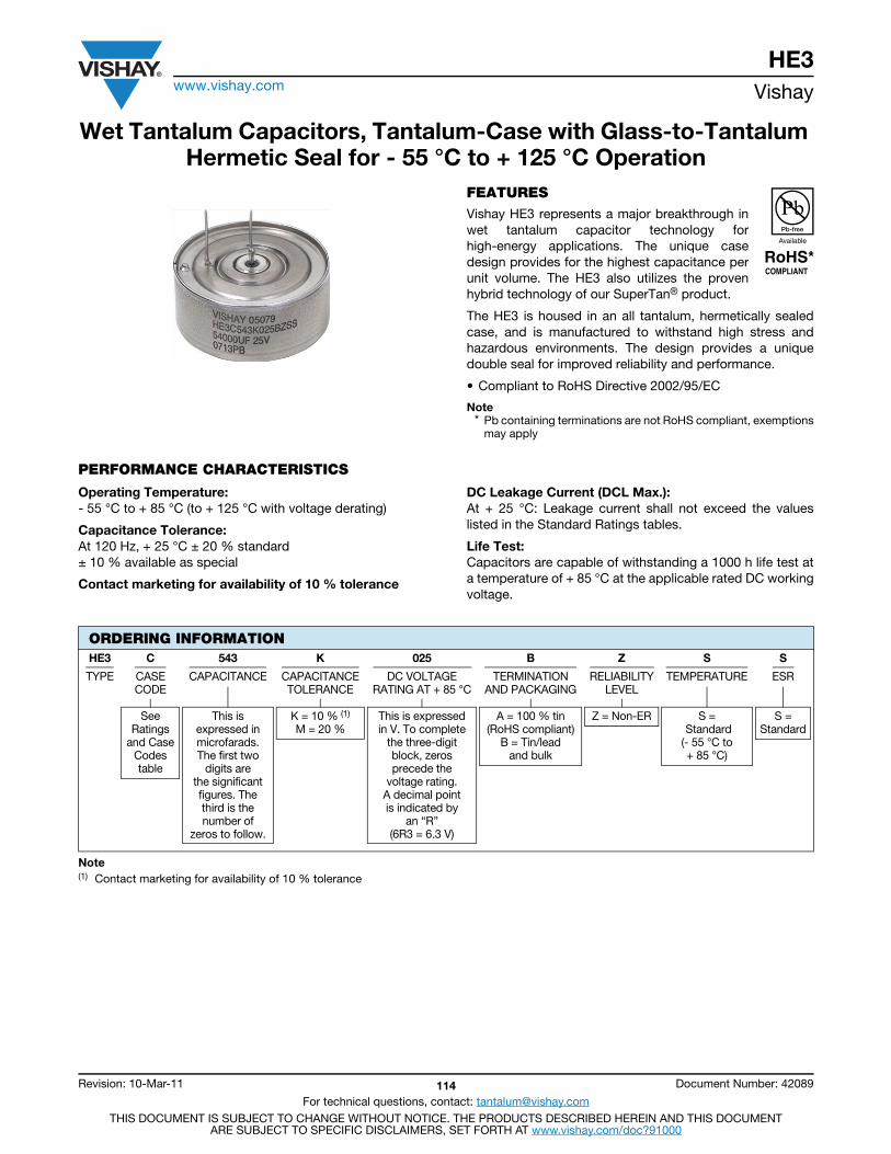
HE3www.vishay.com Vishay
Revision: 10-Mar-11 114 Document Number: 42089
For technical questions, contact: [email protected] DOCUMENT IS SUBJECT TO CHANGE WITHOUT NOTICE. THE PRODUCTS DESCRIBED HEREIN AND THIS DOCUMENT
ARE SUBJECT TO SPECIFIC DISCLAIMERS, SET FORTH AT www.vishay.com/doc?91000
Wet Tantalum Capacitors, Tantalum-Case with Glass-to-Tantalum Hermetic Seal for - 55 °C to + 125 °C Operation
FEATURESVishay HE3 represents a major breakthrough inwet tantalum capacitor technology forhigh-energy applications. The unique casedesign provides for the highest capacitance perunit volume. The HE3 also utilizes the provenhybrid technology of our SuperTan® product.
The HE3 is housed in an all tantalum, hermetically sealedcase, and is manufactured to withstand high stress andhazardous environments. The design provides a uniquedouble seal for improved reliability and performance.
• Compliant to RoHS Directive 2002/95/EC
Note* Pb containing terminations are not RoHS compliant, exemptions
may apply
PERFORMANCE CHARACTERISTICS
Operating Temperature:- 55 °C to + 85 °C (to + 125 °C with voltage derating)
Capacitance Tolerance:At 120 Hz, + 25 °C ± 20 % standard± 10 % available as special
Contact marketing for availability of 10 % tolerance
DC Leakage Current (DCL Max.): At + 25 °C: Leakage current shall not exceed the valueslisted in the Standard Ratings tables.
Life Test:Capacitors are capable of withstanding a 1000 h life test ata temperature of + 85 °C at the applicable rated DC workingvoltage.
Note(1) Contact marketing for availability of 10 % tolerance
ORDERING INFORMATIONHE3 C 543 K 025 B Z S S
TYPE CASECODE
CAPACITANCE CAPACITANCETOLERANCE
DC VOLTAGERATING AT + 85 °C
TERMINATIONAND PACKAGING
RELIABILITYLEVEL
TEMPERATURE ESR
SeeRatings
and CaseCodestable
This isexpressed inmicrofarads.The first two
digits arethe significantfigures. Thethird is thenumber of
zeros to follow.
K = 10 % (1)
M = 20 %This is expressedin V. To complete
the three-digitblock, zerosprecede the
voltage rating.A decimal pointis indicated by
an “R”(6R3 = 6.3 V)
A = 100 % tin(RoHS compliant)
B = Tin/lead and bulk
Z = Non-ER S = Standard(- 55 °C to+ 85 °C)
S =Standard
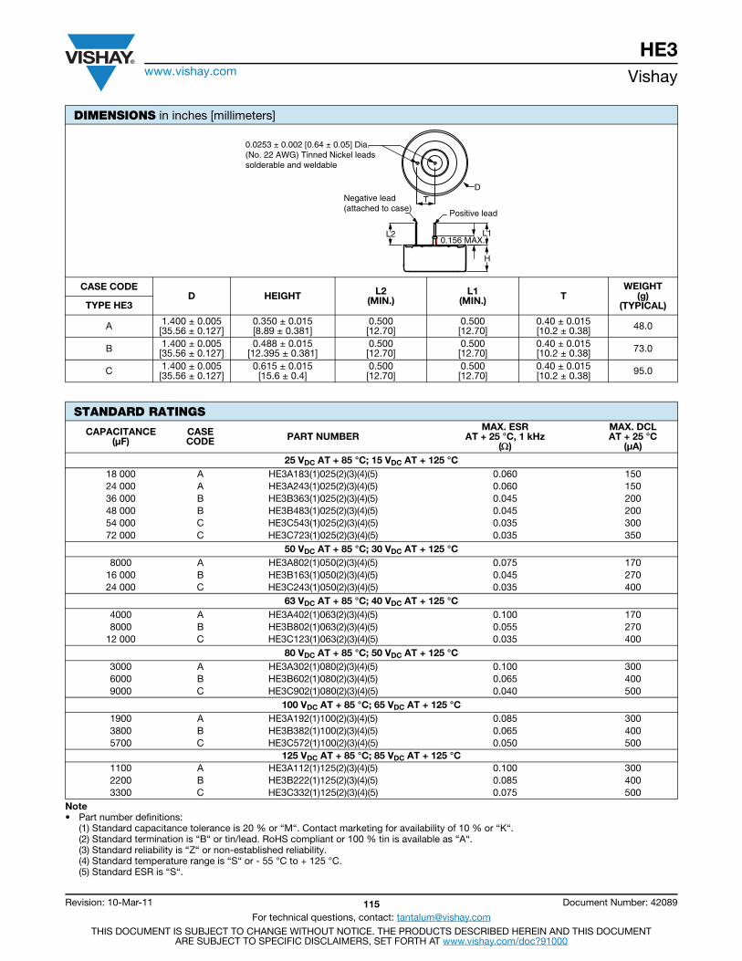
HE3www.vishay.com Vishay
Revision: 10-Mar-11 115 Document Number: 42089
For technical questions, contact: [email protected] DOCUMENT IS SUBJECT TO CHANGE WITHOUT NOTICE. THE PRODUCTS DESCRIBED HEREIN AND THIS DOCUMENT
ARE SUBJECT TO SPECIFIC DISCLAIMERS, SET FORTH AT www.vishay.com/doc?91000
DIMENSIONS in inches [millimeters]
CASE CODE D HEIGHT L2
(MIN.) L1
(MIN.) TWEIGHT
(g) (TYPICAL) TYPE HE3
A 1.400 ± 0.005[35.56 ± 0.127]
0.350 ± 0.015[8.89 ± 0.381]
0.500[12.70]
0.500[12.70]
0.40 ± 0.015[10.2 ± 0.38] 48.0
B 1.400 ± 0.005[35.56 ± 0.127]
0.488 ± 0.015[12.395 ± 0.381]
0.500[12.70]
0.500[12.70]
0.40 ± 0.015[10.2 ± 0.38] 73.0
C 1.400 ± 0.005 [35.56 ± 0.127]
0.615 ± 0.015[15.6 ± 0.4]
0.500[12.70]
0.500[12.70]
0.40 ± 0.015[10.2 ± 0.38] 95.0
STANDARD RATINGS
CAPACITANCE (μF)
CASE CODE PART NUMBER
MAX. ESRAT + 25 °C, 1 kHz
()
MAX. DCL AT + 25 °C
(μA)25 VDC AT + 85 °C; 15 VDC AT + 125 °C
18 000 A HE3A183(1)025(2)(3)(4)(5) 0.060 15024 000 A HE3A243(1)025(2)(3)(4)(5) 0.060 15036 000 B HE3B363(1)025(2)(3)(4)(5) 0.045 20048 000 B HE3B483(1)025(2)(3)(4)(5) 0.045 20054 000 C HE3C543(1)025(2)(3)(4)(5) 0.035 30072 000 C HE3C723(1)025(2)(3)(4)(5) 0.035 350
50 VDC AT + 85 °C; 30 VDC AT + 125 °C8000 A HE3A802(1)050(2)(3)(4)(5) 0.075 170
16 000 B HE3B163(1)050(2)(3)(4)(5) 0.045 27024 000 C HE3C243(1)050(2)(3)(4)(5) 0.035 400
63 VDC AT + 85 °C; 40 VDC AT + 125 °C4000 A HE3A402(1)063(2)(3)(4)(5) 0.100 1708000 B HE3B802(1)063(2)(3)(4)(5) 0.055 270
12 000 C HE3C123(1)063(2)(3)(4)(5) 0.035 40080 VDC AT + 85 °C; 50 VDC AT + 125 °C
3000 A HE3A302(1)080(2)(3)(4)(5) 0.100 3006000 B HE3B602(1)080(2)(3)(4)(5) 0.065 4009000 C HE3C902(1)080(2)(3)(4)(5) 0.040 500
100 VDC AT + 85 °C; 65 VDC AT + 125 °C1900 A HE3A192(1)100(2)(3)(4)(5) 0.085 3003800 B HE3B382(1)100(2)(3)(4)(5) 0.065 4005700 C HE3C572(1)100(2)(3)(4)(5) 0.050 500
125 VDC AT + 85 °C; 85 VDC AT + 125 °C1100 A HE3A112(1)125(2)(3)(4)(5) 0.100 3002200 B HE3B222(1)125(2)(3)(4)(5) 0.085 4003300 C HE3C332(1)125(2)(3)(4)(5) 0.075 500
Note• Part number definitions:
(1) Standard capacitance tolerance is 20 % or “M“. Contact marketing for availability of 10 % or “K“.(2) Standard termination is “B“ or tin/lead. RoHS compliant or 100 % tin is available as “A“.(3) Standard reliability is “Z“ or non-established reliability.(4) Standard temperature range is “S“ or - 55 °C to + 125 °C.(5) Standard ESR is “S“.
D
Positive lead
L2
H
L1
T
0.0253 ± 0.002 [0.64 ± 0.05] Dia.(No. 22 AWG) Tinned Nickel leadssolderable and weldable
Negative lead(attached to case)
0.156 MAX..
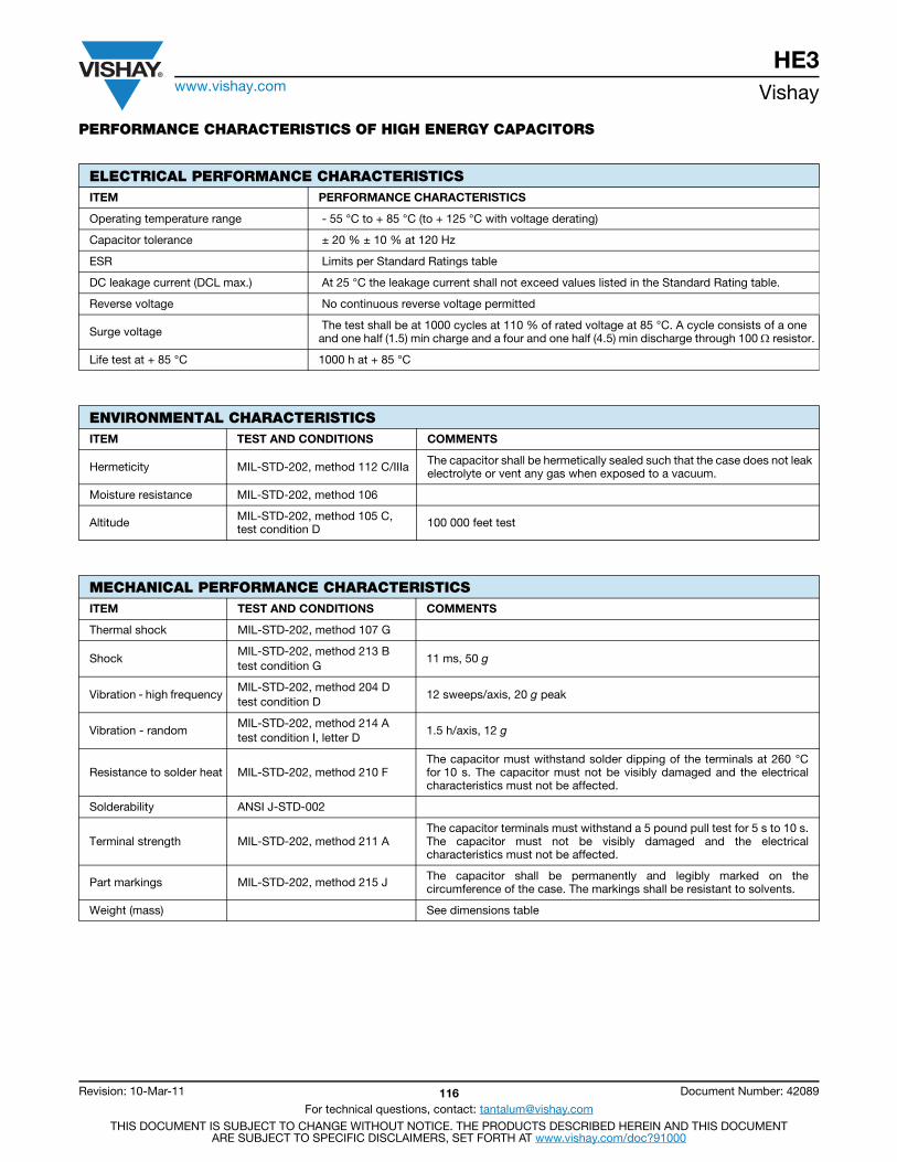
HE3www.vishay.com Vishay
Revision: 10-Mar-11 116 Document Number: 42089
For technical questions, contact: [email protected] DOCUMENT IS SUBJECT TO CHANGE WITHOUT NOTICE. THE PRODUCTS DESCRIBED HEREIN AND THIS DOCUMENT
ARE SUBJECT TO SPECIFIC DISCLAIMERS, SET FORTH AT www.vishay.com/doc?91000
PERFORMANCE CHARACTERISTICS OF HIGH ENERGY CAPACITORS
ELECTRICAL PERFORMANCE CHARACTERISTICSITEM PERFORMANCE CHARACTERISTICS
Operating temperature range - 55 °C to + 85 °C (to + 125 °C with voltage derating)
Capacitor tolerance ± 20 % ± 10 % at 120 Hz
ESR Limits per Standard Ratings table
DC leakage current (DCL max.) At 25 °C the leakage current shall not exceed values listed in the Standard Rating table.
Reverse voltage No continuous reverse voltage permitted
Surge voltage The test shall be at 1000 cycles at 110 % of rated voltage at 85 °C. A cycle consists of a one and one half (1.5) min charge and a four and one half (4.5) min discharge through 100 resistor.
Life test at + 85 °C 1000 h at + 85 °C
ENVIRONMENTAL CHARACTERISTICSITEM TEST AND CONDITIONS COMMENTS
Hermeticity MIL-STD-202, method 112 C/IIIa The capacitor shall be hermetically sealed such that the case does not leak electrolyte or vent any gas when exposed to a vacuum.
Moisture resistance MIL-STD-202, method 106
Altitude MIL-STD-202, method 105 C, test condition D 100 000 feet test
MECHANICAL PERFORMANCE CHARACTERISTICSITEM TEST AND CONDITIONS COMMENTS
Thermal shock MIL-STD-202, method 107 G
ShockMIL-STD-202, method 213 B test condition G
11 ms, 50 g
Vibration - high frequencyMIL-STD-202, method 204 D test condition D
12 sweeps/axis, 20 g peak
Vibration - randomMIL-STD-202, method 214 A test condition I, letter D
1.5 h/axis, 12 g
Resistance to solder heat MIL-STD-202, method 210 FThe capacitor must withstand solder dipping of the terminals at 260 °Cfor 10 s. The capacitor must not be visibly damaged and the electricalcharacteristics must not be affected.
Solderability ANSI J-STD-002
Terminal strength MIL-STD-202, method 211 AThe capacitor terminals must withstand a 5 pound pull test for 5 s to 10 s.The capacitor must not be visibly damaged and the electricalcharacteristics must not be affected.
Part markings MIL-STD-202, method 215 J The capacitor shall be permanently and legibly marked on thecircumference of the case. The markings shall be resistant to solvents.
Weight (mass) See dimensions table
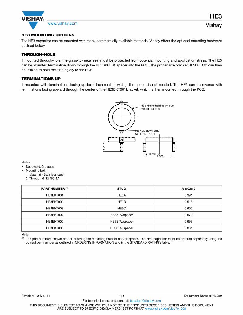
HE3www.vishay.com Vishay
Revision: 10-Mar-11 117 Document Number: 42089
For technical questions, contact: [email protected] DOCUMENT IS SUBJECT TO CHANGE WITHOUT NOTICE. THE PRODUCTS DESCRIBED HEREIN AND THIS DOCUMENT
ARE SUBJECT TO SPECIFIC DISCLAIMERS, SET FORTH AT www.vishay.com/doc?91000
HE3 MOUNTING OPTIONSThe HE3 capacitor can be mounted with many commercially available methods. Vishay offers the optional mounting hardwareoutlined below.
THROUGH-HOLEIf mounted through-hole, the glass-to-metal seal must be protected from potential mounting and application stress. The HE3can be mounted termination down through the HE3SPC001 spacer into the PCB. The proper size bracket HE3BKT00* can thenbe utilized to hold the HE3 rigidly to the PCB.
TERMINATIONS UPIf mounted with terminations facing up for attachment to wiring, the spacer is not needed. The HE3 can be reverse withterminations facing upward through the center of the HE3BKT00* bracket, which is then mounted through the PCB.
Notes• Spot weld, 2 places• Mounting bolt:
1. Material - Stainless steel2. Thread - 6-32 NC-2A
Note(1) The part numbers shown are for ordering the mounting bracket and/or spacer. The HE3 capacitor must be ordered separately using the
correct part number as outlined in ORDERING INFORMATION and in the STANDARD RATINGS table.
PART NUMBER (1) STUD A ± 0.010
HE3BKT001 HE3A 0.391
HE3BKT002 HE3B 0.518
HE3BKT003 HE3C 0.605
HE3BKT004 HE3A W/spacer 0.572
HE3BKT005 HE3B W/spacer 0.699
HE3BKT006 HE3C W/spacer 0.831
HE3 Nickel hold down cupMS-HE-04-003
HE Hold down studMS-C-17-315-1
A
0.7891.579
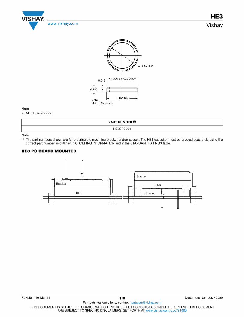
HE3www.vishay.com Vishay
Revision: 10-Mar-11 118 Document Number: 42089
For technical questions, contact: [email protected] DOCUMENT IS SUBJECT TO CHANGE WITHOUT NOTICE. THE PRODUCTS DESCRIBED HEREIN AND THIS DOCUMENT
ARE SUBJECT TO SPECIFIC DISCLAIMERS, SET FORTH AT www.vishay.com/doc?91000
Note• Mat. L: Aluminum
Note(1) The part numbers shown are for ordering the mounting bracket and/or spacer. The HE3 capacitor must be ordered separately using the
correct part number as outlined in ORDERING INFORMATION and in the STANDARD RATINGS table.
HE3 PC BOARD MOUNTED
PART NUMBER (1)
HE3SPC001
1.150 Dia.
1.326 ± 0.002 Dia.
1.400 Dia.
0.195
0.015
NoteMat. L: Aluminum
Bracket
Bracket
HE3
HE3
Spacer
Contents
200D, 202D.....................120
211D ...............................130
285D ...............................132
XTH-K-L-M-V ..................103
MC2 ................................135
MT2.................................140Assemblies
ArraysModules

Wet Tantalum Capacitors Wet Sintered Anode TANTALEX® Components
TANTAPAK® Capacitor Assemblies
200D, 202DVishay
www.vishay.com For technical questions, contact: [email protected] Document Number: 40027120 Revision: 14-Oct-05
FEATURESTANTAPAK® Wet Sintered Anode capacitor assemblies arewidely used in filter, coupling, bypass and time-delay circuitsin computers, missiles, airborne equipment, radar and firecontrol systems.
TANTAPAK® capacitor assemblies are available in 3 standardcase styles and 13 case codes. Type 200D units areconstructed with the negative terminal connected to thecase; they are available only in the “A” case, in five casecodes. Model 202D capacitors are the commercialequivalent of Tansitor Style RW, Mallory-NACC Style TL andare designed to meet MIL-DTL-3965 and DSCC DWG04021.
PERFORMANCE CHARACTERISTICS
Operating Temperature: - 55 °C to + 125 °C.
Capacitance Tolerance: At 120 Hz, + 25 °C. ± 20 %standard. ± 10 % available.
DC Leakage Current (DCL Max.):
At + 25 °C: Leakage current shall not exceed the valueslisted in the Standard Ratings Tables.
Life Test: Capacitors shall withstand 2000 hours at atemperature of + 85 °C or + 125 °C at the rated DC workingvoltage.
Following the life test:1. DCL shall not exceed the original requirement.2. ESR shall not be more than 130 % of the initial
requirement.3. Capacitance shall not change more than ± 25 %.
ORDERING INFORMATION202D 318 X0 006 A1
MODEL CAPACITANCE CAPACITANCE TOLERANCE
DC VOLTAGE RATING AT + 85 C
CASE CODE
200D = Negative terminal connected to case (Available only in 'A' Cases)
202D = Both terminals insulated from case
This is expressed in picofarads. The first two digits are the
significant figures. The third is the number of zeros to follow
X0 = ± 20 % X9 = ± 10 %
This is expressed in volts. To complete the three-digit block, zeros precede the
voltage rating
See Dimensional
Configurations
DIMENSIONS in inches [millimeters]
MODEL 200D MODEL 202D
SERIES “A” CASE
0.067 [1.70]DIA. HOLE
0.203 ± 0.031[5.16 ± 0.79]
CL
0.625 ± 0.015[15.88 ± 0.38]
1.275 ± 0.015[32.39 ± 0.38]
CL
0.062 x 0.125[1.57 x 3.18]
HOLE
0.266 ± 0.031[6.76 ± 0.79]
H ± 0.031[0.79]
0.625 ± 0.015[15.88 ± 0.38]
CL
0.625 ± 0.015[15.88 ± 0.38]
0.720 ± 0.031[18.29 ± 0.79]
1.305 ± 0.031[33.15 ± 0.79]
90° ± 1°
90° ± 1°
Series “B” Case
0.062 x 0.125[1.57 x 3.18]
Hole
H ± 0.062[1.57]
1.593 ± 0.062[40.46 ± 1.57]
CL
0.281 ± 0.031[7.14 ± 0.79]
CL1.000 ± 0.062[25.4 ± 1.57]
0.750 ± 0.015[19.05 ± 0.38]
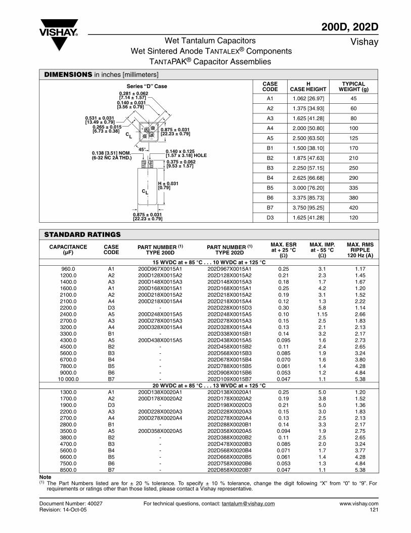
Document Number: 40027 For technical questions, contact: [email protected] www.vishay.comRevision: 14-Oct-05 121
200D, 202DWet Tantalum Capacitors
Wet Sintered Anode TANTALEX® ComponentsTANTAPAK® Capacitor Assemblies
Vishay
DIMENSIONS in inches [millimeters]CASE CODE
H CASE HEIGHT
TYPICAL WEIGHT (g)
A1 1.062 [26.97] 45
A2 1.375 [34.93] 60
A3 1.625 [41.28] 80
A4 2.000 [50.80] 100
A5 2.500 [63.50] 125
B1 1.500 [38.10] 170
B2 1.875 [47.63] 210
B3 2.250 [57.15] 250
B4 2.625 [66.68] 290
B5 3.000 [76.20] 335
B6 3.375 [85.73] 380
B7 3.750 [95.25] 420
D3 1.625 [41.28] 120
Series “D” Case
45°
CL
CL
0.281 ± 0.062[7.14 ± 1.57]
0.140 ± 0.031[3.56 ± 0.79]
0.531 ± 0.031[13.49 ± 0.79]
0.265 ± 0.015[6.73 ± 0.38]
0.138 [3.51] NOM.(6-32 NC 2A THD.)
0.140 x 0.125[1.57 x 3.18] HOLE0.375 ± 0.062[9.53 ± 1.57]
H ± 0.031[0.79]
0.875 ± 0.031[22.23 ± 0.79]
0.875 ± 0.031[22.23 ± 0.79]
STANDARD RATINGS
CAPACITANCE (µF)
CASE CODE
PART NUMBER (1)
TYPE 200DPART NUMBER (1)
TYPE 202D
MAX. ESRat + 25 °C
()
MAX. IMP.at - 55 °C
()
MAX. RMS RIPPLE
120 Hz (A)15 WVDC at + 85 °C . . . 10 WVDC at + 125 °C
960.0 A1 200D967X0015A1 202D967X0015A1 0.25 3.1 1.17 1200.0 A2 200D128X0015A2 202D128X0015A2 0.21 2.3 1.45 1400.0 A3 200D148X0015A3 202D148X0015A3 0.18 1.7 1.67 1600.0 A1 200D168X0015A1 202D168X0015A1 0.25 4.2 1.20 2100.0 A2 200D218X0015A2 202D218X0015A2 0.19 3.1 1.52 2100.0 A4 200D218X0015A4 202D218X0015A4 0.12 1.3 2.22 2200.0 D3 - 202D228X0015D3 0.30 5.8 1.14 2400.0 A5 200D248X0015A5 202D248X0015A5 0.10 1.15 2.66 2700.0 A3 200D278X0015A3 202D278X0015A3 0.15 2.5 1.83 3200.0 A4 200D328X0015A4 202D328X0015A4 0.13 2.1 2.13 3300.0 B1 - 202D338X0015B1 0.14 3.2 2.17 4300.0 A5 200D438X0015A5 202D438X0015A5 0.095 1.6 2.73 4500.0 B2 - 202D458X0015B2 0.11 2.4 2.65 5600.0 B3 - 202D568X0015B3 0.085 1.9 3.24 6700.0 B4 - 202D678X0015B4 0.070 1.6 3.80 7800.0 B5 - 202D788X0015B5 0.061 1.4 4.28 9000.0 B6 - 202D908X0015B6 0.053 1.2 4.84
10 000.0 B7 - 202D109X0015B7 0.047 1.1 5.38 20 WVDC at + 85 °C . . . 13 WVDC at + 125 °C
1300.0 A1 200D138X0020A1 202D138X0020A1 0.25 5.0 1.20 1700.0 A2 200D178X0020A2 202D178X0020A2 0.19 3.8 1.52 1900.0 D3 - 202D198X0020D3 0.21 5.0 1.36 2200.0 A3 200D228X0020A3 202D228X0020A3 0.15 3.0 1.83 2700.0 A4 200D278X0020A4 202D278X0020A4 0.13 2.5 2.13 2800.0 B1 - 202D288X0020B1 0.14 3.3 2.17 3500.0 A5 200D358X0020A5 202D358X0020A5 0.094 1.9 2.75 3800.0 B2 - 202D388X0020B2 0.11 2.5 2.65 4700.0 B3 - 202D478X0020B3 0.085 2.0 3.24 5600.0 B4 - 202D568X0020B4 0.071 1.7 3.77 6600.0 B5 - 202D668X0020B5 0.061 1.4 4.28 7500.0 B6 - 202D758X0020B6 0.053 1.3 4.84 8500.0 B7 - 202D858X0020B7 0.047 1.1 5.38
Note (1) The Part Numbers listed are for ± 20 % tolerance. To specify ± 10 % tolerance, change the digit following “X” from “0” to “9”. For
requirements or ratings other than those listed, please contact a Vishay representative.
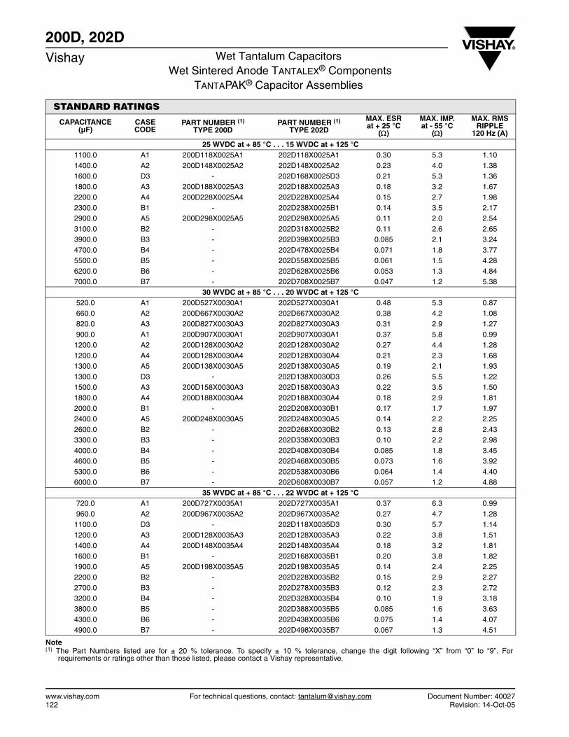
www.vishay.com For technical questions, contact: [email protected] Document Number: 40027122 Revision: 14-Oct-05
200D, 202DVishay Wet Tantalum Capacitors
Wet Sintered Anode TANTALEX® ComponentsTANTAPAK® Capacitor Assemblies
STANDARD RATINGS
CAPACITANCE (µF)
CASE CODE
PART NUMBER (1)
TYPE 200DPART NUMBER (1)
TYPE 202D
MAX. ESRat + 25 °C
()
MAX. IMP.at - 55 °C
()
MAX. RMS RIPPLE
120 Hz (A)
25 WVDC at + 85 °C . . . 15 WVDC at + 125 °C 1100.0 A1 200D118X0025A1 202D118X0025A1 0.30 5.3 1.10 1400.0 A2 200D148X0025A2 202D148X0025A2 0.23 4.0 1.38 1600.0 D3 - 202D168X0025D3 0.21 5.3 1.36 1800.0 A3 200D188X0025A3 202D188X0025A3 0.18 3.2 1.67 2200.0 A4 200D228X0025A4 202D228X0025A4 0.15 2.7 1.98 2300.0 B1 - 202D238X0025B1 0.14 3.5 2.17 2900.0 A5 200D298X0025A5 202D298X0025A5 0.11 2.0 2.54 3100.0 B2 - 202D318X0025B2 0.11 2.6 2.65 3900.0 B3 - 202D398X0025B3 0.085 2.1 3.24 4700.0 B4 - 202D478X0025B4 0.071 1.8 3.77 5500.0 B5 - 202D558X0025B5 0.061 1.5 4.28 6200.0 B6 - 202D628X0025B6 0.053 1.3 4.84 7000.0 B7 - 202D708X0025B7 0.047 1.2 5.38
30 WVDC at + 85 °C . . . 20 WVDC at + 125 °C 520.0 A1 200D527X0030A1 202D527X0030A1 0.48 5.3 0.87 660.0 A2 200D667X0030A2 202D667X0030A2 0.38 4.2 1.08 820.0 A3 200D827X0030A3 202D827X0030A3 0.31 2.9 1.27 900.0 A1 200D907X0030A1 202D907X0030A1 0.37 5.8 0.99 1200.0 A2 200D128X0030A2 202D128X0030A2 0.27 4.4 1.28 1200.0 A4 200D128X0030A4 202D128X0030A4 0.21 2.3 1.68 1300.0 A5 200D138X0030A5 202D138X0030A5 0.19 2.1 1.93 1300.0 D3 - 202D138X0030D3 0.26 5.5 1.22 1500.0 A3 200D158X0030A3 202D158X0030A3 0.22 3.5 1.50 1800.0 A4 200D188X0030A4 202D188X0030A4 0.18 2.9 1.81 2000.0 B1 - 202D208X0030B1 0.17 1.7 1.97 2400.0 A5 200D248X0030A5 202D248X0030A5 0.14 2.2 2.25 2600.0 B2 - 202D268X0030B2 0.13 2.8 2.43 3300.0 B3 - 202D338X0030B3 0.10 2.2 2.98 4000.0 B4 - 202D408X0030B4 0.085 1.8 3.45 4600.0 B5 - 202D468X0030B5 0.073 1.6 3.92 5300.0 B6 - 202D538X0030B6 0.064 1.4 4.40 6000.0 B7 - 202D608X0030B7 0.057 1.2 4.88
35 WVDC at + 85 °C . . . 22 WVDC at + 125 °C 720.0 A1 200D727X0035A1 202D727X0035A1 0.37 6.3 0.99 960.0 A2 200D967X0035A2 202D967X0035A2 0.27 4.7 1.28 1100.0 D3 - 202D118X0035D3 0.30 5.7 1.14 1200.0 A3 200D128X0035A3 202D128X0035A3 0.22 3.8 1.51 1400.0 A4 200D148X0035A4 202D148X0035A4 0.18 3.2 1.81 1600.0 B1 - 202D168X0035B1 0.20 3.8 1.82 1900.0 A5 200D198X0035A5 202D198X0035A5 0.14 2.4 2.25 2200.0 B2 - 202D228X0035B2 0.15 2.9 2.27 2700.0 B3 - 202D278X0035B3 0.12 2.3 2.72 3200.0 B4 - 202D328X0035B4 0.10 1.9 3.18 3800.0 B5 - 202D388X0035B5 0.085 1.6 3.63 4300.0 B6 - 202D438X0035B6 0.075 1.4 4.07 4900.0 B7 - 202D498X0035B7 0.067 1.3 4.51
Note (1) The Part Numbers listed are for ± 20 % tolerance. To specify ± 10 % tolerance, change the digit following “X” from “0” to “9”. For
requirements or ratings other than those listed, please contact a Vishay representative.
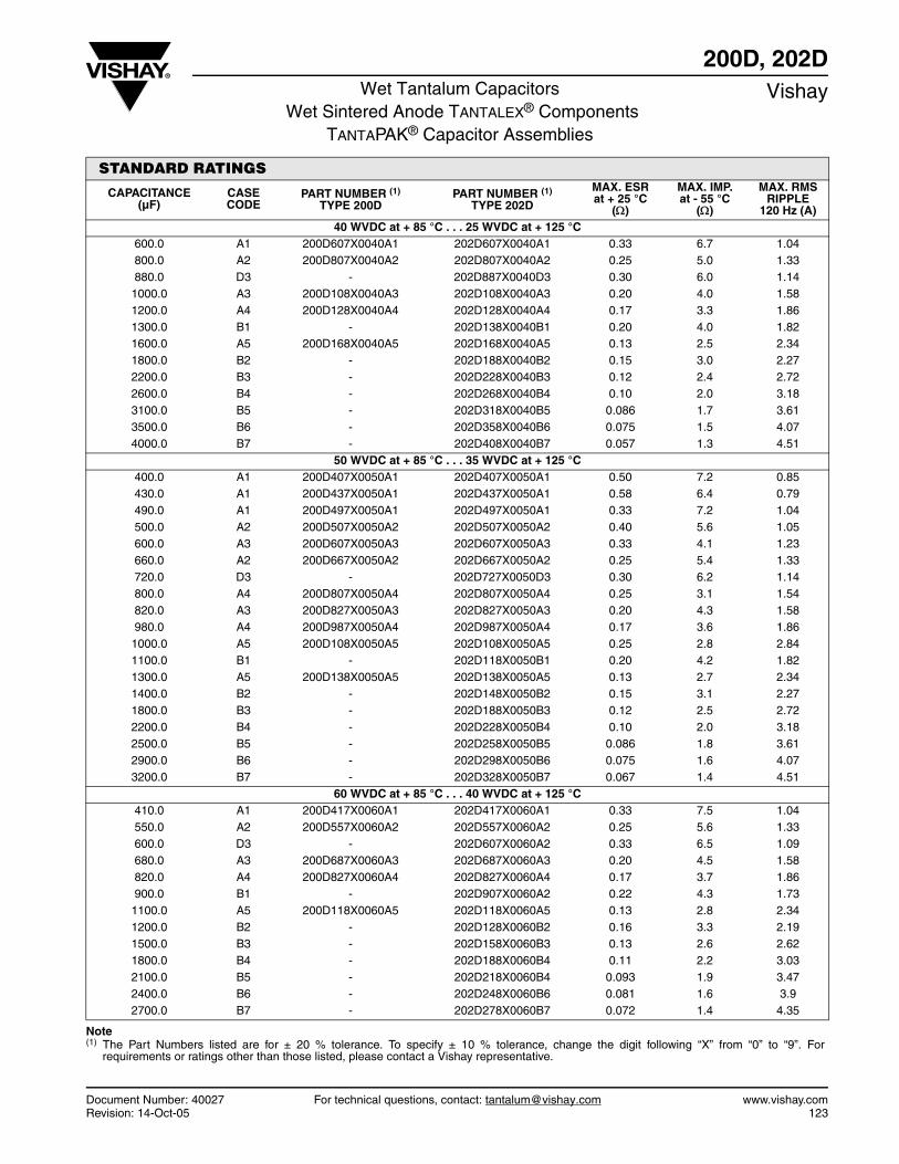
Document Number: 40027 For technical questions, contact: [email protected] www.vishay.comRevision: 14-Oct-05 123
200D, 202DWet Tantalum Capacitors
Wet Sintered Anode TANTALEX® ComponentsTANTAPAK® Capacitor Assemblies
Vishay
STANDARD RATINGS
CAPACITANCE (µF)
CASE CODE
PART NUMBER (1)
TYPE 200DPART NUMBER (1)
TYPE 202D
MAX. ESRat + 25 °C
()
MAX. IMP.at - 55 °C
()
MAX. RMS RIPPLE
120 Hz (A)40 WVDC at + 85 °C . . . 25 WVDC at + 125 °C
600.0 A1 200D607X0040A1 202D607X0040A1 0.33 6.7 1.04 800.0 A2 200D807X0040A2 202D807X0040A2 0.25 5.0 1.33 880.0 D3 - 202D887X0040D3 0.30 6.0 1.14 1000.0 A3 200D108X0040A3 202D108X0040A3 0.20 4.0 1.58 1200.0 A4 200D128X0040A4 202D128X0040A4 0.17 3.3 1.86 1300.0 B1 - 202D138X0040B1 0.20 4.0 1.82 1600.0 A5 200D168X0040A5 202D168X0040A5 0.13 2.5 2.34 1800.0 B2 - 202D188X0040B2 0.15 3.0 2.27 2200.0 B3 - 202D228X0040B3 0.12 2.4 2.72 2600.0 B4 - 202D268X0040B4 0.10 2.0 3.18 3100.0 B5 - 202D318X0040B5 0.086 1.7 3.61 3500.0 B6 - 202D358X0040B6 0.075 1.5 4.07 4000.0 B7 - 202D408X0040B7 0.057 1.3 4.51
50 WVDC at + 85 °C . . . 35 WVDC at + 125 °C 400.0 A1 200D407X0050A1 202D407X0050A1 0.50 7.2 0.85 430.0 A1 200D437X0050A1 202D437X0050A1 0.58 6.4 0.79 490.0 A1 200D497X0050A1 202D497X0050A1 0.33 7.2 1.04 500.0 A2 200D507X0050A2 202D507X0050A2 0.40 5.6 1.05 600.0 A3 200D607X0050A3 202D607X0050A3 0.33 4.1 1.23 660.0 A2 200D667X0050A2 202D667X0050A2 0.25 5.4 1.33 720.0 D3 - 202D727X0050D3 0.30 6.2 1.14 800.0 A4 200D807X0050A4 202D807X0050A4 0.25 3.1 1.54 820.0 A3 200D827X0050A3 202D827X0050A3 0.20 4.3 1.58 980.0 A4 200D987X0050A4 202D987X0050A4 0.17 3.6 1.86 1000.0 A5 200D108X0050A5 202D108X0050A5 0.25 2.8 2.84 1100.0 B1 - 202D118X0050B1 0.20 4.2 1.82 1300.0 A5 200D138X0050A5 202D138X0050A5 0.13 2.7 2.34 1400.0 B2 - 202D148X0050B2 0.15 3.1 2.27 1800.0 B3 - 202D188X0050B3 0.12 2.5 2.72 2200.0 B4 - 202D228X0050B4 0.10 2.0 3.18 2500.0 B5 - 202D258X0050B5 0.086 1.8 3.61 2900.0 B6 - 202D298X0050B6 0.075 1.6 4.07 3200.0 B7 - 202D328X0050B7 0.067 1.4 4.51
60 WVDC at + 85 °C . . . 40 WVDC at + 125 °C 410.0 A1 200D417X0060A1 202D417X0060A1 0.33 7.5 1.04 550.0 A2 200D557X0060A2 202D557X0060A2 0.25 5.6 1.33 600.0 D3 - 202D607X0060A2 0.33 6.5 1.09 680.0 A3 200D687X0060A3 202D687X0060A3 0.20 4.5 1.58 820.0 A4 200D827X0060A4 202D827X0060A4 0.17 3.7 1.86 900.0 B1 - 202D907X0060A2 0.22 4.3 1.73 1100.0 A5 200D118X0060A5 202D118X0060A5 0.13 2.8 2.34 1200.0 B2 - 202D128X0060B2 0.16 3.3 2.19 1500.0 B3 - 202D158X0060B3 0.13 2.6 2.62 1800.0 B4 - 202D188X0060B4 0.11 2.2 3.03 2100.0 B5 - 202D218X0060B4 0.093 1.9 3.47 2400.0 B6 - 202D248X0060B6 0.081 1.6 3.9 2700.0 B7 - 202D278X0060B7 0.072 1.4 4.35
Note(1) The Part Numbers listed are for ± 20 % tolerance. To specify ± 10 % tolerance, change the digit following “X” from “0” to “9”. For
requirements or ratings other than those listed, please contact a Vishay representative.
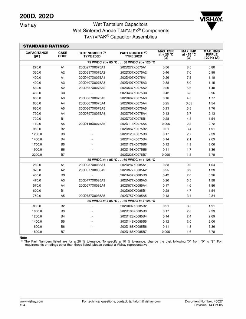
www.vishay.com For technical questions, contact: [email protected] Document Number: 40027124 Revision: 14-Oct-05
200D, 202DVishay Wet Tantalum Capacitors
Wet Sintered Anode TANTALEX® ComponentsTANTAPAK® Capacitor Assemblies
STANDARD RATINGS
CAPACITANCE (µF)
CASE CODE
PART NUMBER (1)
TYPE 200DPART NUMBER (1)
TYPE 202D
MAX. ESRat + 25 °C
()
MAX. IMP.at - 55 °C
()
MAX. RMS RIPPLE
120 Hz (A)75 WVDC at + 85 °C . . . 50 WVDC at + 125 °C
270.0 A1 200D277X0075A1 202D277X0075A1 0.56 8.5 0.80
330.0 A2 200D337X0075A2 202D337X0075A2 0.46 7.0 0.98
400.0 A1 200D407X0075A1 202D407X0075A1 0.26 7.5 1.18
400.0 A3 200D407X0075A3 202D407X0075A3 0.38 5.0 1.15
530.0 A2 200D537X0075A2 202D537X0075A2 0.20 5.6 1.48
480.0 D3 - 202D487X0075D3 0.42 6.8 0.96
660.0 A3 200D667X0075A3 202D667X0075A3 0.16 4.5 1.77
600.0 A4 200D607X0075A4 202D607X0075A4 0.25 3.65 1.54
660.0 A5 200D667X0075A5 202D667X0075A5 0.23 3.5 1.76
790.0 A4 200D797X0075A4 202D797X0075A4 0.13 3.7 2.13
720.0 B1 - 202D727X0075B1 0.28 4.5 1.54
110.0 A5 200D118X0075A5 202D118X0075A5 0.096 2.8 2.72
960.0 B2 - 202D967X0075B2 0.21 3.4 1.91
1200.0 B3 - 202D128X0075B3 0.17 2.7 2.29
1400.0 B4 - 202D148X0075B4 0.14 2.1 2.69
1700.0 B5 - 202D178X0075B5 0.12 1.9 3.06
1900.0 B6 - 202D198X0075B6 0.11 1.7 3.36
2200.0 B7 - 202D228X0075B7 0.095 1.5 3.78
85 WVDC at + 85 °C . . . 60 WVDC at + 125 °C
280.0 A1 200D287X0085A1 202D287X0085A1 0.33 9.2 1.04
370.0 A2 200D377X0085A2 202D377X0085A2 0.25 6.9 1.33
400.0 D3 - 202D407X0085D3 0.42 7.0 0.96
470.0 A3 200D477X0085A3 202D477X0085A3 0.20 5.5 1.58
570.0 A4 200D577X0085A4 202D577X0085A4 0.17 4.6 1.86
600.0 B1 - 202D607X0085B1 0.28 4.7 1.54
750.0 A5 200D757X0085A5 202D757X0085A5 0.13 3.4 2.34
85 WVDC at + 85 °C . . . 60 WVDC at + 125 °C
800.0 B2 - 202D807X0085B2 0.21 3.5 1.91
1000.0 B3 - 202D108X0085B3 0.17 2.8 2.29
1200.0 B4 - 202D128X0085B4 0.14 2.4 2.69
1400.0 B5 - 202D148X0085B5 0.12 2.0 3.06
1600.0 B6 - 202D168X0085B6 0.11 1.8 3.36
1800.0 B7 - 202D188X0085B7 0.095 1.6 3.78
Note (1) The Part Numbers listed are for ± 20 % tolerance. To specify ± 10 % tolerance, change the digit following “X” from “0” to “9”. For
requirements or ratings other than those listed, please contact a Vishay representative.

Document Number: 40027 For technical questions, contact: [email protected] www.vishay.comRevision: 14-Oct-05 125
200D, 202DWet Tantalum Capacitors
Wet Sintered Anode TANTALEX® ComponentsTANTAPAK® Capacitor Assemblies
Vishay
STANDARD RATINGS
CAPACITANCE (µF)
CASE CODE
PART NUMBER (1)
TYPE 200DPART NUMBER (1)
TYPE 202D
MAX. ESRat + 25 °C
()
MAX. IMP.at - 55 °C
()
MAX. RMS RIPPLE
120 Hz (A)85 WVDC at + 85 °C . . . 60 WVDC at + 125 °C
280.0 A1 200D287X0085A1 202D287X0085A1 0.33 9.2 1.04 370.0 A2 200D377X0085A2 202D377X0085A2 0.25 6.9 1.33 400.0 D3 - 202D407X0085D3 0.42 7.0 0.96 470.0 A3 200D477X0085A3 202D477X0085A3 0.20 5.5 1.58 570.0 A4 200D577X0085A4 202D577X0085A4 0.17 4.6 1.86 600.0 B1 - 202D607X0085B1 0.28 4.7 1.54 750.0 A5 200D757X0085A5 202D757X0085A5 0.13 3.4 2.34 800.0 B2 - 202D807X0085B2 0.21 3.5 1.91 1000.0 B3 - 202D108X0085B3 0.17 2.8 2.29 1200.0 B4 - 202D128X0085B4 0.14 2.4 2.69 1400.0 B5 - 202D148X0085B5 0.12 2.0 3.06 1600.0 B6 - 202D168X0085B6 0.11 1.8 3.36 1800.0 B7 - 202D188X0085B7 0.095 1.6 3.78
100 WVDC at + 85 °C . . . 70 WVDC at + 125 °C 170.0 A1 200D177X0100A1 202D177X0100A1 0.94 15.0 0.62 220.0 A2 200D227X0100A2 202D227X0100A2 0.72 11.6 0.78 260.0 A1 200D267X0100A1 202D267X0100A1 0.40 8.3 0.95 260.0 A3 200D267X0100A3 202D267X0100A3 0.61 8.0 0.91 340.0 D3 - 202D347X0100D3 0.75 7.5 0.72 350.0 A2 200D357X0100A2 202D357X0100A2 0.30 6.2 1.21 350.0 A4 200D357X0100A4 202D357X0100A4 0.45 6.5 1.15 440.0 A3 200D447X0100A3 202D447X0100A3 0.24 5.0 1.44 440.0 A5 200D447X0100A5 202D447X0100A5 0.36 5.8 1.40 510.0 B1 - 202D517X0100B1 0.28 4.8 1.54 530.0 A4 200D537X0100A4 202D537X0100A4 0.20 4.2 1.72 680.0 B2 - 202D687X0100B2 0.21 3.6 1.91 700.0 A5 200D707X0100A5 202D707X0100A5 0.15 3.1 2.18 850.0 B3 - 202D857X0100B3 0.17 2.9 2.29 1000.0 B4 - 202D108X0100B4 0.14 2.4 2.69 1200.0 B5 - 202D128X0100B5 0.12 2.1 3.06 1400.0 B6 - 202D148X0100B6 0.11 1.8 3.36 1500.0 B7 - 202D158X0100B7 0.095 1.6 3.78
125 WVDC at + 85 °C . . . 80 WVDC at + 125 °C 170.0 A1 200D177X0125A1 202D177X0125A1 0.40 15.0 0.95 220.0 A2 200D227X0125A2 202D227X0125A2 0.30 12.0 1.21 220.0 D3 - 202D227X0125D3 0.42 8.0 0.96 280.0 A3 200D287X0125A3 202D287X0125A3 0.24 9.0 1.44 340.0 A4 200D347X0125A4 202D347X0125A4 0.20 7.5 1.72 340.0 B1 - 202D347X0125B1 0.28 5.4 1.54 560.0 B3 - 202D567X0125B3 0.17 3.2 2.29 670.0 B4 - 202D677X0125B4 0.14 2.7 2.69 790.0 B5 - 202D797X0125B5 0.12 2.4 3.06 900.0 B6 - 202D907X0125B6 0.11 2.0 3.38 1000.0 B7 - 202D108X0125B7 0.095 1.8 3.78
150 WVDC at + 85 °C . . . 100 WVDC at + 125 °C 70.0 A1 200D706X0150A1 202D706X0150A1 2.27 28.8 0.40 90.0 A2 200D906X0150A2 202D906X0150A2 1.77 22.4 0.50 100.0 A3 200D107X0150A3 202D107X0150A3 1.59 16.4 0.56 140.0 A4 200D147X0150A4 202D147X0150A4 1.14 12.4 0.72 180.0 A5 200D187X0150A5 202D187X0150A5 0.88 11.2 0.90
Note(1) The Part Numbers listed are for ± 20 % tolerance. To specify ± 10 % tolerance, change the digit following “X” from “0” to “9”. For
requirements or ratings other than those listed, please contact a Vishay representative.
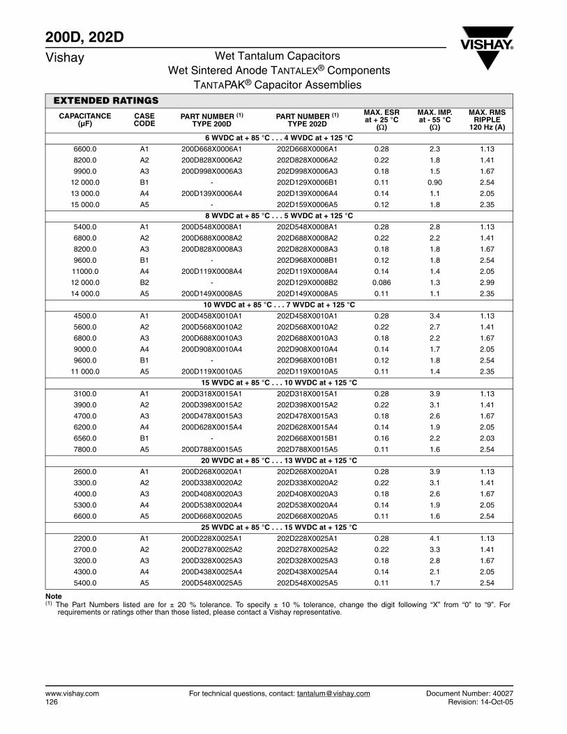
www.vishay.com For technical questions, contact: [email protected] Document Number: 40027126 Revision: 14-Oct-05
200D, 202DVishay Wet Tantalum Capacitors
Wet Sintered Anode TANTALEX® ComponentsTANTAPAK® Capacitor Assemblies
EXTENDED RATINGS
CAPACITANCE (µF)
CASE CODE
PART NUMBER (1)
TYPE 200DPART NUMBER (1)
TYPE 202D
MAX. ESRat + 25 °C
()
MAX. IMP.at - 55 °C
()
MAX. RMS RIPPLE
120 Hz (A)6 WVDC at + 85 °C . . . 4 WVDC at + 125 °C
6600.0 A1 200D668X0006A1 202D668X0006A1 0.28 2.3 1.13
8200.0 A2 200D828X0006A2 202D828X0006A2 0.22 1.8 1.41
9900.0 A3 200D998X0006A3 202D998X0006A3 0.18 1.5 1.67
12 000.0 B1 - 202D129X0006B1 0.11 0.90 2.54
13 000.0 A4 200D139X0006A4 202D139X0006A4 0.14 1.1 2.05
15 000.0 A5 - 202D159X0006A5 0.12 1.8 2.35
8 WVDC at + 85 °C . . . 5 WVDC at + 125 °C
5400.0 A1 200D548X0008A1 202D548X0008A1 0.28 2.8 1.13
6800.0 A2 200D688X0008A2 202D688X0008A2 0.22 2.2 1.41
8200.0 A3 200D828X0008A3 202D828X0008A3 0.18 1.8 1.67
9600.0 B1 - 202D968X0008B1 0.12 1.8 2.54
11000.0 A4 200D119X0008A4 202D119X0008A4 0.14 1.4 2.05
12 000.0 B2 - 202D129X0008B2 0.086 1.3 2.99
14 000.0 A5 200D149X0008A5 202D149X0008A5 0.11 1.1 2.35
10 WVDC at + 85 °C . . . 7 WVDC at + 125 °C
4500.0 A1 200D458X0010A1 202D458X0010A1 0.28 3.4 1.13
5600.0 A2 200D568X0010A2 202D568X0010A2 0.22 2.7 1.41
6800.0 A3 200D688X0010A3 202D688X0010A3 0.18 2.2 1.67
9000.0 A4 200D908X0010A4 202D908X0010A4 0.14 1.7 2.05
9600.0 B1 - 202D968X0010B1 0.12 1.8 2.54
11 000.0 A5 200D119X0010A5 202D119X0010A5 0.11 1.4 2.35
15 WVDC at + 85 °C . . . 10 WVDC at + 125 °C
3100.0 A1 200D318X0015A1 202D318X0015A1 0.28 3.9 1.13
3900.0 A2 200D398X0015A2 202D398X0015A2 0.22 3.1 1.41
4700.0 A3 200D478X0015A3 202D478X0015A3 0.18 2.6 1.67
6200.0 A4 200D628X0015A4 202D628X0015A4 0.14 1.9 2.05
6560.0 B1 - 202D668X0015B1 0.16 2.2 2.03
7800.0 A5 200D788X0015A5 202D788X0015A5 0.11 1.6 2.54
20 WVDC at + 85 °C . . . 13 WVDC at + 125 °C
2600.0 A1 200D268X0020A1 202D268X0020A1 0.28 3.9 1.13
3300.0 A2 200D338X0020A2 202D338X0020A2 0.22 3.1 1.41
4000.0 A3 200D408X0020A3 202D408X0020A3 0.18 2.6 1.67
5300.0 A4 200D538X0020A4 202D538X0020A4 0.14 1.9 2.05
6600.0 A5 200D668X0020A5 202D668X0020A5 0.11 1.6 2.54
25 WVDC at + 85 °C . . . 15 WVDC at + 125 °C
2200.0 A1 200D228X0025A1 202D228X0025A1 0.28 4.1 1.13
2700.0 A2 200D278X0025A2 202D278X0025A2 0.22 3.3 1.41
3200.0 A3 200D328X0025A3 202D328X0025A3 0.18 2.8 1.67
4300.0 A4 200D438X0025A4 202D438X0025A4 0.14 2.1 2.05
5400.0 A5 200D548X0025A5 202D548X0025A5 0.11 1.7 2.54
Note(1) The Part Numbers listed are for ± 20 % tolerance. To specify ± 10 % tolerance, change the digit following “X” from “0” to “9”. For
requirements or ratings other than those listed, please contact a Vishay representative.
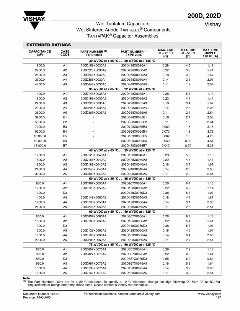
Document Number: 40027 For technical questions, contact: [email protected] www.vishay.comRevision: 14-Oct-05 127
200D, 202DWet Tantalum Capacitors
Wet Sintered Anode TANTALEX® ComponentsTANTAPAK® Capacitor Assemblies
Vishay
EXTENDED RATINGS
CAPACITANCE (µF)
CASE CODE
PART NUMBER (1)
TYPE 200DPART NUMBER (1)
TYPE 202D
MAX. ESRat + 25 °C
()
MAX. IMP.at - 55 °C
()
MAX. RMS RIPPLE
120 Hz (A)30 WVDC at + 85 °C . . . 20 WVDC at + 125 °C
1800.0 A1 200D188X0030A1 202D188X0030A1 0.28 4.5 1.13
2200.0 A2 200D228X0030A2 202D228X0030A2 0.22 3.6 1.41
2600.0 A3 200D268X0030A3 202D268X0030A3 0.18 3.0 1.67
3500.0 A4 200D358X0030A4 202D358X0030A4 0.14 2.3 2.05
4400.0 A5 200D448X0030A5 202D448X0030A5 0.11 1.8 2.54
35 WVDC at + 85 °C . . . 22 WVDC at + 125 °C
1400.0 A1 200D148X0035A1 202D148X0035A1 0.28 5.1 1.13
1800.0 A2 200D188X0035A2 202D188X0035A2 0.22 4.1 1.41
2200.0 A3 200D228X0035A3 202D228X0035A3 0.18 3.4 1.67
2900.0 A4 200D298X0035A4 202D298X0035A4 0.14 2.6 2.05
3600.0 A5 200D368X0035A5 202D368X0035A5 0.11 2.1 2.54
3900.0 B1 - 202D398X0035B1 0.16 2.7 2.03
5500.0 B2 - 202D558X0035B2 0.11 1.9 2.64
7000.0 B3 - 202D708X0035B3 0.089 1.5 3.16
8600.0 B4 - 202D868X0035B4 0.073 1.2 3.72
10 000.0 B5 - 202D109X0035B5 0.062 1.0 4.25
12 000.0 B6 - 202D129X0035B6 0.053 0.90 4.84
13 000.0 B7 - 202D139X0035B7 0.047 0.79 5.38
40 WVDC at + 85 °C . . . 25 WVDC at + 125 °C
1200.0 A1 200D128X0040A1 202D128X0040A1 0.28 5.5 1.13
1500.0 A2 200D158X0040A2 202D158X0040A2 0.22 4.4 1.41
1800.0 A3 200D188X0040A3 202D188X0040A3 0.18 3.7 1.67
2400.0 A4 200D248X0040A4 202D248X0040A4 0.14 2.8 2.05
3000.0 A5 200D308X0040A5 202D308X0040A5 0.11 2.3 2.54
50 WVDC at + 85 °C . . . 35 WVDC at + 125 °C
960.0 A1 200D967X0050A1 202D967X0050A1 0.28 6.1 1.13
1200.0 A2 200D128X0050A2 202D128X0050A2 0.22 4.9 1.14
1300.0 D3 - 202D138X0050D3 0.38 5.5 1.01
1400.0 A3 200D148X0050A3 202D148X0050A3 0.18 4.1 1.67
1900.0 A4 200D198X0050A4 202D198X0050A4 0.14 3.1 2.05
2400.0 A5 200D248X0050A5 202D248X0050A5 0.11 2.5 2.54
60 WVDC at + 85 °C . . . 40 WVDC at + 125 °C
800.0 A1 200D807X0060A1 202D807X0060A1 0.28 6.8 1.13
1000.0 A2 200D108X0060A2 202D108X0060A2 0.22 5.4 1.41
1100.0 D3 - 202D118X0060D3 0.38 5.8 1.01
1200.0 A3 200D128X0060A3 202D128X0060A3 0.18 4.5 1.67
1600.0 A4 200D168X0060A4 202D168X0060A4 0.14 3.4 2.05
2000.0 A5 200D208X0060A5 202D208X0060A5 0.11 2.7 2.54
75 WVDC at + 85 °C . . . 50 WVDC at + 125 °C
650.0 A1 200D657X0075A1 202D657X0075A1 0.28 7.9 1.13
820.0 A2 200D827X0075A2 202D827X0075A2 0.22 6.3 1.41
880.0 D3 - 202D887X0075D3 0.55 6.0 0.84
980.0 A3 200D987X0075A3 202D987X0075A3 0.18 5.2 1.64
1300.0 A4 200D138X0075A4 202D138X0075A4 0.14 3.9 2.05
1600.0 A5 200D168X0075A5 202D168X0075A5 0.11 3.2 2.54
Note(1) The Part Numbers listed are for ± 20 % tolerance. To specify ± 10 % tolerance, change the digit following “X” from “0” to “9”. For
requirements or ratings other than those listed, please contact a Vishay representative.
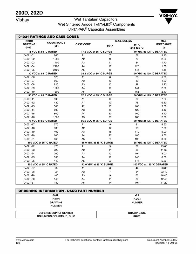
www.vishay.com For technical questions, contact: [email protected] Document Number: 40027128 Revision: 14-Oct-05
200D, 202DVishay Wet Tantalum Capacitors
Wet Sintered Anode TANTALEX® ComponentsTANTAPAK® Capacitor Assemblies
04021 RATINGS AND CASE CODESDSCC
DRAWING 04021
CAPACITANCE (µF)
CASE CODEMAX. DCL µA MAX.
IMPEDANCE 25 °C
85 °Cand 125 °C
15 VDC at 85 °C RATED 17.2 VDC at 85 °C SURGE 10 VDC at 125 °C DERATED 04021-01 960 A1 7 58 3.10 04021-02 1200 A2 9 72 2.30 04021-03 1400 A3 11 84 1.70 04021-04 2100 A4 16 126 1.30 04021-05 2400 A5 18 144 1.15
30 VDC at 85 °C RATED 34.5 VDC at 85 °C SURGE 20 VDC at 125 °C DERATED 04021-06 520 A1 8 63 5.30 04021-07 660 A2 10 80 4.20 04021-08 820 A3 13 99 2.90 04021-09 1200 A4 18 144 2.30 04021-10 1300 A5 20 156 2.10
50 VDC at 85 °C RATED 57.5 VDC at 85 °C SURGE 30 VDC at 125 °C DERATED 04021-11 400 A1 10 80 7.20 04021-12 430 A1 10 78 6.40 04021-13 500 A2 13 100 5.60 04021-14 600 A3 15 120 4.10 04021-15 800 A4 20 160 3.10 04021-16 1000 A5 23 180 2.80
75 VDC at 85 °C RATED 86.2 VDC at 85 °C SURGE 50 VDC at 125 °C DERATED 04021-17 270 A1 9 81 8.50 04021-18 330 A2 12 99 7.00 04021-19 400 A3 15 119 5.00 04021-20 600 A4 20 180 3.65 04021-21 660 A5 23 198 3.50
100 VDC at 85 °C RATED 115.0 VDC at 85 °C SURGE 65 VDC at 125 °C DERATED 04021-22 170 A1 9 68 15.00 04021-23 220 A2 11 88 11.60 04021-24 260 A3 13 104 8.00 04021-25 350 A4 18 140 6.50 04021-26 440 A5 22 176 5.80
150 VDC at 85 °C RATED 172.0 VDC at 85 °C SURGE 100 VDC at 125 °C DERATED 04021-27 70 A1 6 42 28.80 04021-28 90 A2 7 54 22.40 04021-29 100 A3 9 60 16.40 04021-30 140 A4 11 84 12.40 04021-31 180 A5 14 104 11.20
ORDERING INFORMATION - DSCC PART NUMBER04021 -29
DSCC DRAWING NUMBER
DASH NUMBER
DEFENSE SUPPLY CENTER, COLUMBUS COLUMBUS, OHIO
DRAWING NO.04021
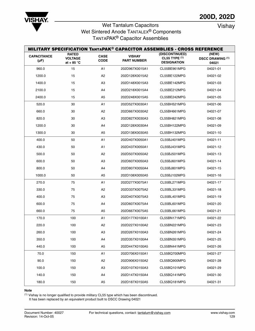
Document Number: 40027 For technical questions, contact: [email protected] www.vishay.comRevision: 14-Oct-05 129
200D, 202DWet Tantalum Capacitors
Wet Sintered Anode TANTALEX® ComponentsTANTAPAK® Capacitor Assemblies
Vishay
MILITARY SPECIFICATION TANTAPAK® CAPACITOR ASSEMBLIES - CROSS REFERENCE
CAPACITANCE (µF)
RATED VOLTAGE at + 85 °C
CASE CODE
VISHAY PART NUMBER
(DISCONTINUED)CL55 TYPE (1)
DESIGNATION
(NEW)DSCC DRAWING (1)
04021
960.0 15 A1 202D967X0015A1 CL55BE961MPG 04021-01
1200.0 15 A2 202D128X0015A2 CL55BE122MPG 04021-02
1400.0 15 A3 202D148X0015A3 CL55BE142MPG 04021-03
2100.0 15 A4 202D218X0015A4 CL55BE212MPG 04021-04
2400.0 15 A5 202D248X0015A5 CL55BE242MPG 04021-05
520.0 30 A1 202D527X0030A1 CL55BH521MPG 04021-06
660.0 30 A2 202D667X0030A2 CL55BH661MPG 04021-07
820.0 30 A3 202D827X0030A3 CL55BH821MPG 04021-08
1200.0 30 A4 202D128X0030A4 CL55BH122MPG 04021-09
1300.0 30 A5 202D138X0030A5 CL55BH132MPG 04021-10
400.0 50 A1 202D407X0050A1 CL55BJ401MPG 04021-11
430.0 50 A1 202D437X0050A1 CL55BJ431MPG 04021-12
500.0 50 A2 202D507X0050A2 CL55BJ501MPG 04021-13
600.0 50 A3 202D607X0050A3 CL55BJ601MPG 04021-14
800.0 50 A4 202D807X0050A4 CL55BJ801MPG 04021-15
1000.0 50 A5 202D108X0050A5 CL55BJ102MPG 04021-16
270.0 75 A1 202D277X0075A1 CL55BL271MPG 04021-17
330.0 75 A2 202D337X0075A2 CL55BL331MPG 04021-18
400.0 75 A3 202D407X0075A3 CL55BL401MPG 04021-19
600.0 75 A4 202D607X0075A4 CL55BL601MPG 04021-20
660.0 75 A5 202D667X0075A5 CL55BL661MPG 04021-21
170.0 100 A1 202D177X0100A1 CL55BN171MPG 04021-22
220.0 100 A2 202D227X0100A2 CL55BN221MPG 04021-23
260.0 100 A3 202D267X0100A3 CL55BN261MPG 04021-24
350.0 100 A4 202D357X0100A4 CL55BN351MPG 04021-25
440.0 100 A5 202D447X0100A5 CL55BN441MPG 04021-26
70.0 150 A1 202D706X0150A1 CL55BQ700MPG 04021-27
90.0 150 A2 202D906X0150A2 CL55BQ900MPG 04021-28
100.0 150 A3 202D107X0150A3 CL55BQ101MPG 04021-29
140.0 150 A4 202D147X0150A4 CL55BQ141MPG 04021-30
180.0 150 A5 202D187X0150A5 CL55BQ181MPG 04021-31
Note(1) Vishay is no longer qualified to provide military CL55 type which has been discontinued.
It has been replaced by an equivalent product built to DSCC Drawing 04021

211Dwww.vishay.com Vishay
Revision: 10-Nov-11 130 Document Number: 40111
For technical questions, contact: [email protected] DOCUMENT IS SUBJECT TO CHANGE WITHOUT NOTICE. THE PRODUCTS DESCRIBED HEREIN AND THIS DOCUMENT
ARE SUBJECT TO SPECIFIC DISCLAIMERS, SET FORTH AT www.vishay.com/doc?91000
Type 211D Wet Tantalum Capacitor Array with Tantalum Cased Tantalum Internal Components for - 55 °C to + 125 °C Operation
FEATURESVishay 211D series was designed as an upgrade to the olderand mature 200D and 202D Tantalpak® Capacitorassemblies. The 211D is constructed using tantalumcapacitors, similar to the Vishay 135D series or theMIL-PRF-39006/22 or /25 styles. This enables the 211D toexhibit the improved performance characteristics of thetantalum-cased capacitors. Capable of withstanding 3.0 Vreverse. The 211D has applicability in new designs whenused for energy storage, filtering and similar functions.
PERFORMANCE CHARACTERISTICSOperating Temperature: - 55 °C to + 125 °CCapacitance Tolerance: At 120 Hz, + 25 °C, ± 20 %Standard: ± 10 % availableDC Leakage Current (DCL maximum):At + 25 °C: Leakage current shall not exceed the valueslisted in the Standard Ratings table.
Life Test: Capacitors shall withstand 2000 h at atemperature of + 85 °C or + 125 °C at the rated DC workingvoltage. Following the life test:1. DCL shall not exceed the original requirement2. ESR shall not exceed the original requirement3. Capacitance shall not change more than ± 10 %
ORDERING INFORMATION211D 228 X 030 A5
MODEL CAPACITANCE CAPACITANCETOLERANCE
DC VOLTAGE RATINGAT + 85 °C
CASE CODE
This is expressed inpicofarads. The first two
digits are significantfigures. The third is the
number of zeros.
X0 = ± 20 %X9 = ± 10 %
This is expressed in volts.To complete the three digitblock, zeros precede thevoltage rating. A decimal
point is indicated by an “R”(6R3 = 6.3 V).
See dimensionalconfigurations
DIMENSIONS
SERIES “A” CASE SERIES “B” CASE CASE CODE HCASE HEIGHT
A1 1.062 [26.97]
A2 1.375 [34.93]
A3 1.625 [41.28]
A4 2.000 [50.60]
A5 2.500 [63.50]
B1 1.500 [38.10]
B2 1.875 [47.63]
B3 2.250 [57.15]
B4 2.625 [66.68]
B5 3.000 [76.20]
B6 3.375 [85.73]
B7 3.750 [95.25]
0.720 ± 0.031
1.305 ± 0.031
1.275 ± 0.015
0.281 ± 0.031
0.625 ± 0.015
H ± 0.031
0.281 ± 0.031
0.750 ± 0.015
H ± 0.062
1.000 ± 0.062
1.593 ± 0.062
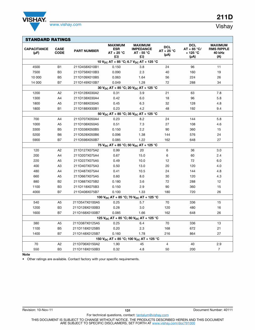
211Dwww.vishay.com Vishay
Revision: 10-Nov-11 131 Document Number: 40111
For technical questions, contact: [email protected] DOCUMENT IS SUBJECT TO CHANGE WITHOUT NOTICE. THE PRODUCTS DESCRIBED HEREIN AND THIS DOCUMENT
ARE SUBJECT TO SPECIFIC DISCLAIMERS, SET FORTH AT www.vishay.com/doc?91000
STANDARD RATINGS
CAPACITANCE(μF)
CASE CODE PART NUMBER
MAXIMUM ESR
AT + 25 °C()
MAXIMUM IMPEDANCE
AT - 55 °C()
DCLAT + 25 °C
(μA)
DCLAT + 85 °C/
+ 125 °C(μA)
MAXIMUM RMS RIPPLE
40 kHz(A)
10 VDC AT + 85 °C; 6.7 VDC AT + 125 °C
4500 B1 211D458X010B1 0.150 3.8 24 96 11
7500 B3 211D758X010B3 0.090 2.3 40 160 19
10 000 B5 211D109X010B5 0.063 1.64 56 224 26
14 000 B7 211D149X010B7 0.049 1.28 72 288 34
30 VDC AT + 85 °C; 20 VDC AT + 125 °C
1200 A2 211D128X030A2 0.31 3.9 21 63 7.8
1300 A4 211D138X030A4 0.42 6.0 18 96 5.8
1800 A5 211D188X030A5 0.45 6.3 32 128 4.8
1800 B1 211D188X930B1 0.23 4.2 48 192 9.4
50 VDC AT + 85 °C; 35 VDC AT + 125 °C
700 A4 211D707X050A4 0.23 8.2 24 144 5.8
1000 A5 211D108X050A5 0.51 7.3 27 108 4.6
3300 B5 211D338X050B5 0.150 2.2 90 360 15
5200 B6 211D528X050B6 0.096 1.38 144 576 24
5900 B7 211D598X050B7 0.085 1.22 162 648 27
75 VDC AT + 85 °C; 50 VDC AT + 125 °C
120 A2 211D127X075A2 0.99 20 6 36 3.0
200 A4 211D207X075A4 0.67 15.0 6 60 2.4
220 A5 211D227X075A5 0.49 10.0 12 72 6.0
400 A3 211D407X075A3 0.50 13.0 20 120 4.0
480 A4 211D487X075A4 0.41 10.5 24 144 4.8
660 A5 211D667X075A5 0.60 8.0 30 120 4.3
880 B2 211D887X075B2 0.180 3.6 72 288 12
1100 B3 211D118X075B3 0.150 2.9 90 360 15
4000 B7 211D408X075B7 0.100 1.33 180 720 26
100 VDC AT + 85 °C; 70 VDC AT + 125 °C
540 A5 211D547X0100A5 0.25 5.7 70 336 15
1200 B3 211D128X0100B3 0.28 3.0 120 480 16
1600 B7 211D168X0100B7 0.085 1.66 162 648 26
125 VDC AT + 85 °C; 80 VDC AT + 125 °C
380 A5 211D387X0125A5 0.25 6.4 70 336 13
1100 B5 211D118X0125B5 0.20 2.3 168 672 21
1400 B7 211D148X0125B7 0.160 1.78 216 864 27
150 VDC AT + 85 °C; 100 VDC AT + 125 °C
70 A2 211D706X0150A2 1.90 45 4 40 2.9
550 B3 211D118X0150B3 0.32 4.8 50 200 7
Note• Other ratings are available. Contact factory with your specific requirements.
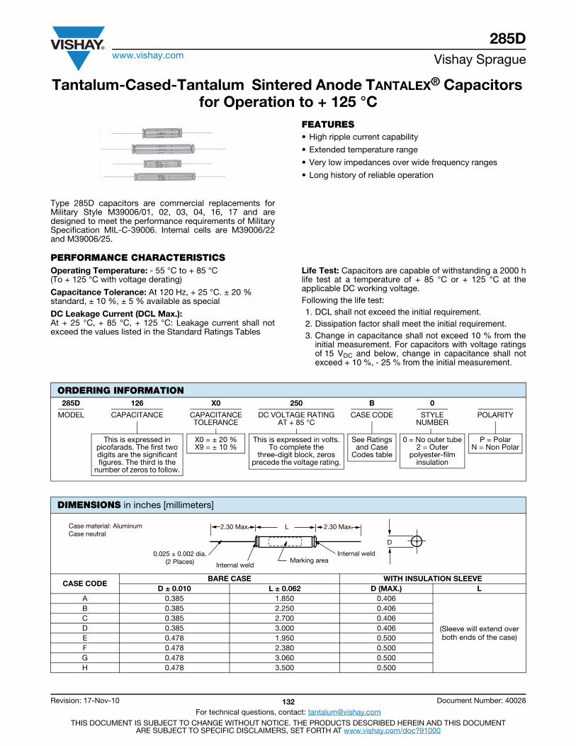
285Dwww.vishay.com Vishay Sprague
Revision: 17-Nov-10 132 Document Number: 40028
For technical questions, contact: [email protected] DOCUMENT IS SUBJECT TO CHANGE WITHOUT NOTICE. THE PRODUCTS DESCRIBED HEREIN AND THIS DOCUMENT
ARE SUBJECT TO SPECIFIC DISCLAIMERS, SET FORTH AT www.vishay.com/doc?91000
Tantalum-Cased-Tantalum Sintered Anode TANTALEX® Capacitors for Operation to + 125 °C
Type 285D capacitors are commercial replacements forMilitary Style M39006/01, 02, 03, 04, 16, 17 and aredesigned to meet the performance requirements of MilitarySpecification MIL-C-39006. Internal cells are M39006/22and M39006/25.
FEATURES• High ripple current capability
• Extended temperature range
• Very low impedances over wide frequency ranges
• Long history of reliable operation
PERFORMANCE CHARACTERISTICSOperating Temperature: - 55 °C to + 85 °C(To + 125 °C with voltage derating)
Capacitance Tolerance: At 120 Hz, + 25 °C. ± 20 % standard, ± 10 %, ± 5 % available as special
DC Leakage Current (DCL Max.):At + 25 °C, + 85 °C, + 125 °C: Leakage current shall notexceed the values listed in the Standard Ratings Tables
Life Test: Capacitors are capable of withstanding a 2000 hlife test at a temperature of + 85 °C or + 125 °C at theapplicable DC working voltage.Following the life test:1. DCL shall not exceed the initial requirement.2. Dissipation factor shall meet the initial requirement.3. Change in capacitance shall not exceed 10 % from the
initial measurement. For capacitors with voltage ratingsof 15 VDC and below, change in capacitance shall notexceed + 10 %, - 25 % from the initial measurement.
ORDERING INFORMATION285D 126 X0 250 B 0
MODEL CAPACITANCE CAPACITANCETOLERANCE
DC VOLTAGE RATINGAT + 85 °C
CASE CODE STYLENUMBER
POLARITY
This is expressed inpicofarads. The first twodigits are the significantfigures. The third is the
number of zeros to follow.
X0 = ± 20 % X9 = ± 10 %
This is expressed in volts.To complete the
three-digit block, zerosprecede the voltage rating.
See Ratingsand Case
Codes table
0 = No outer tube2 = Outer
polyester-filminsulation
P = PolarN = Non Polar
DIMENSIONS in inches [millimeters]
CASE CODEBARE CASE WITH INSULATION SLEEVE
D ± 0.010 L ± 0.062 D (MAX.) LA 0.385 1.850 0.406
(Sleeve will extend over both ends of the case)
B 0.385 2.250 0.406C 0.385 2.700 0.406D 0.385 3.000 0.406E 0.478 1.950 0.500F 0.478 2.380 0.500G 0.478 3.060 0.500H 0.478 3.500 0.500
L2.30 Max. 2.30 Max.
0.025 ± 0.002 dia.(2 Places) Internal weld
Internal weldMarking area
D
Case material: AluminumCase neutral
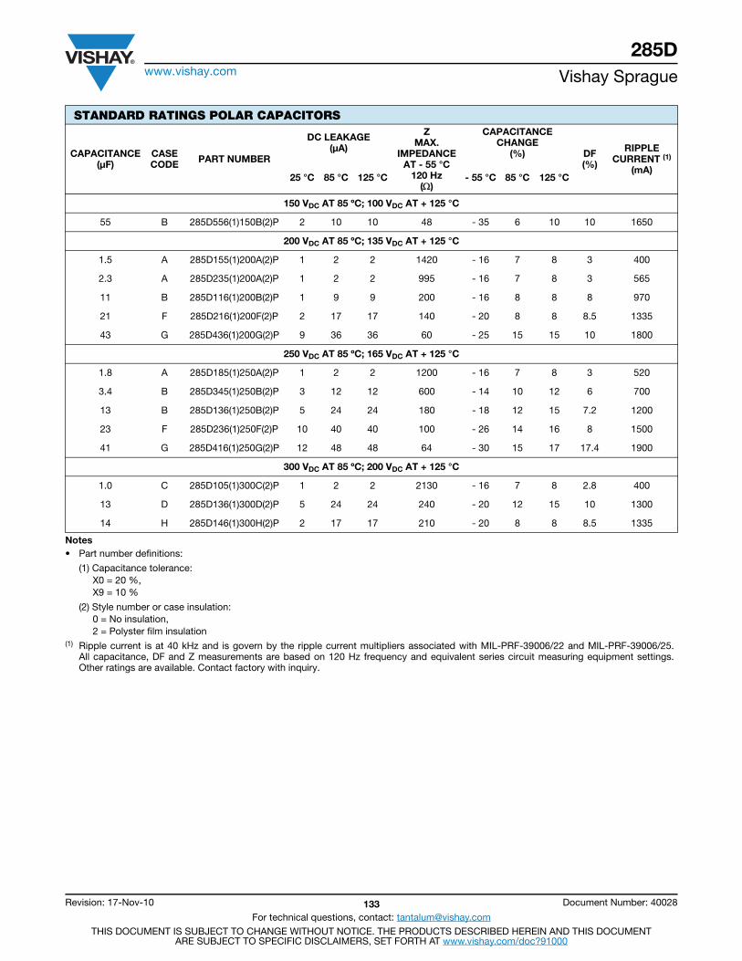
285Dwww.vishay.com Vishay Sprague
Revision: 17-Nov-10 133 Document Number: 40028
For technical questions, contact: [email protected] DOCUMENT IS SUBJECT TO CHANGE WITHOUT NOTICE. THE PRODUCTS DESCRIBED HEREIN AND THIS DOCUMENT
ARE SUBJECT TO SPECIFIC DISCLAIMERS, SET FORTH AT www.vishay.com/doc?91000
STANDARD RATINGS POLAR CAPACITORS
CAPACITANCE(μF)
CASECODE PART NUMBER
DC LEAKAGE (μA)
ZMAX.
IMPEDANCEAT - 55 °C
120 Hz()
CAPACITANCE CHANGE
(%) DF(%)
RIPPLECURRENT (1)
(mA)25 °C 85 °C 125 °C - 55 °C 85 °C 125 °C
150 VDC AT 85 ºC; 100 VDC AT + 125 °C
55 B 285D556(1)150B(2)P 2 10 10 48 - 35 6 10 10 1650
200 VDC AT 85 ºC; 135 VDC AT + 125 °C
1.5 A 285D155(1)200A(2)P 1 2 2 1420 - 16 7 8 3 400
2.3 A 285D235(1)200A(2)P 1 2 2 995 - 16 7 8 3 565
11 B 285D116(1)200B(2)P 1 9 9 200 - 16 8 8 8 970
21 F 285D216(1)200F(2)P 2 17 17 140 - 20 8 8 8.5 1335
43 G 285D436(1)200G(2)P 9 36 36 60 - 25 15 15 10 1800
250 VDC AT 85 ºC; 165 VDC AT + 125 °C
1.8 A 285D185(1)250A(2)P 1 2 2 1200 - 16 7 8 3 520
3.4 B 285D345(1)250B(2)P 3 12 12 600 - 14 10 12 6 700
13 B 285D136(1)250B(2)P 5 24 24 180 - 18 12 15 7.2 1200
23 F 285D236(1)250F(2)P 10 40 40 100 - 26 14 16 8 1500
41 G 285D416(1)250G(2)P 12 48 48 64 - 30 15 17 17.4 1900
300 VDC AT 85 ºC; 200 VDC AT + 125 °C
1.0 C 285D105(1)300C(2)P 1 2 2 2130 - 16 7 8 2.8 400
13 D 285D136(1)300D(2)P 5 24 24 240 - 20 12 15 10 1300
14 H 285D146(1)300H(2)P 2 17 17 210 - 20 8 8 8.5 1335
Notes• Part number definitions:
(1) Capacitance tolerance:X0 = 20 %, X9 = 10 %
(2) Style number or case insulation:0 = No insulation, 2 = Polyster film insulation
(1) Ripple current is at 40 kHz and is govern by the ripple current multipliers associated with MIL-PRF-39006/22 and MIL-PRF-39006/25.All capacitance, DF and Z measurements are based on 120 Hz frequency and equivalent series circuit measuring equipment settings.Other ratings are available. Contact factory with inquiry.

285Dwww.vishay.com Vishay Sprague
Revision: 17-Nov-10 134 Document Number: 40028
For technical questions, contact: [email protected] DOCUMENT IS SUBJECT TO CHANGE WITHOUT NOTICE. THE PRODUCTS DESCRIBED HEREIN AND THIS DOCUMENT
ARE SUBJECT TO SPECIFIC DISCLAIMERS, SET FORTH AT www.vishay.com/doc?91000
STANDARD RATINGS NON-POLAR CAPACITORS
CAPACITANCE(μF)
CASECODE PART NUMBER
DC LEAKAGE(μA)
ZMAX.
IMPEDANCEAT - 55 °C
120 Hz()
CAPACITANCE CHANGE
(%) DF(%)
RIPPLECURRENT (1)
(mA)25 °C 85 °C 125 °C - 55 °C 85 °C 125 °C
6 VDC AT 85 °C; 4 VDC AT + 125 °C
410 B 285D417(1)006B(2)N 3 14 14 36 - 88 16 20 155 1500
15 VDC AT 85 °C; 10 VDC AT + 125 °C
410 F 285D417(1)015F(2)N 6 24 24 44 - 77 20 25 3.6 1800
25 VDC AT 85 °C; 15 VDC AT + 125 °C
34 A 285D346(1)025A(2)N 2 9 9 180 - 40 12 15 22 850
135 B 285D147(1)025B(2)N 3 16 16 66 - 62 13 16 55 1400
30 VDC AT 85 °C; 20 VDC AT + 125 °C
58 A 285D586(1)030A(2)N 1 5 5 60 - 38 8 12 12 1200
235 B 285D247(1)030B(2)N 2 10 10 30 - 65 10 18 30 1800
50 VDC AT 85 °C; 30 VDC AT + 125 °C
34 A 285D346(1)050A(2)N 1 5 5 66 - 25 8 15 7.6 1050
60 B 285D606(1)050B(2)N 4 24 24 98 - 42 12 15 23 1200
235 F 285D247(1)050F(2)N 3 25 25 20 - 45 8 15 31 2100
340 G 285D347(1)050G(2)N 5 40 40 16 - 58 10 20 35 2750
75 VDC AT 85 °C; 50 VDC AT + 125 °C
11 A 285D116(1)075A(2)N 3 12 12 314 - 19 10 12 8.5 600
41 B 285D416(1)075B(2)N 4 24 24 126 - 30 12 15 15.2 1000
55 G 285D556(1)075G(2)N 9 36 36 58 - 35 20 20 12 1850
100 VDC AT 85 °C; 65 VDC AT + 125 °C
5 A 285D504(1)100A(2)N 3 12 12 400 - 35 16 20 4.5 800
11 B 285D116(1)100B(2)N 1 9 9 200 - 16 8 8 7.5 965
15 F 285D156(1)100F(2)N 2 12 12 160 - 16 8 8 7 1240
125 VDC AT 85 °C; 87 VDC AT + 125 °C
1.8 A 285D185(1)125A(2)N 1 2 2 1200 - 16 7 8 2.7 520
7.0 B 285D705(1)125B(2)N 1 7 7 334 - 16 7 8 6 860
23.5 F 285D246(1)125F(2)N 10 40 40 100 - 26 14 16 7.9 1200
28 G 285D286(1)125G(2)N 10 40 40 64 - 25 15 15 6.5 1800
150 VDC AT 85 °C; 100 VDC AT + 125 °C
8.3 E 285D835(1)150E(2)N 1 5 5 264 - 25 5 9 10 1050
200 VDC AT 85 °C; 150 VDC AT + 125 °C
1.2 E 285D125(1)200E(2)N 1 2 2 2260 - 16 7 8 3 600
250 VDC AT 85 °C; 165 VDC AT + 125 °C
1.7 E 285D175(1)250E(2)N 3 12 12 1200 - 14 10 12 6 700
Notes• Part number definitions:
(1) Capacitance tolerance:X0 = 20 %, X9 = 10 %
(2) Style number or case insulation:0 = No insulation, 2 = Polyster film insulation
(1) Ripple current is at 40 kHz and is govern by the ripple current multipliers associated with MIL-PRF-39006/22 and MIL-PRF-39006/25.All capacitance, DF and Z measurements are based on 120 Hz frequency and equivalent series circuit measuring equipment settings.Other ratings are available. Contact factory with inquiry.
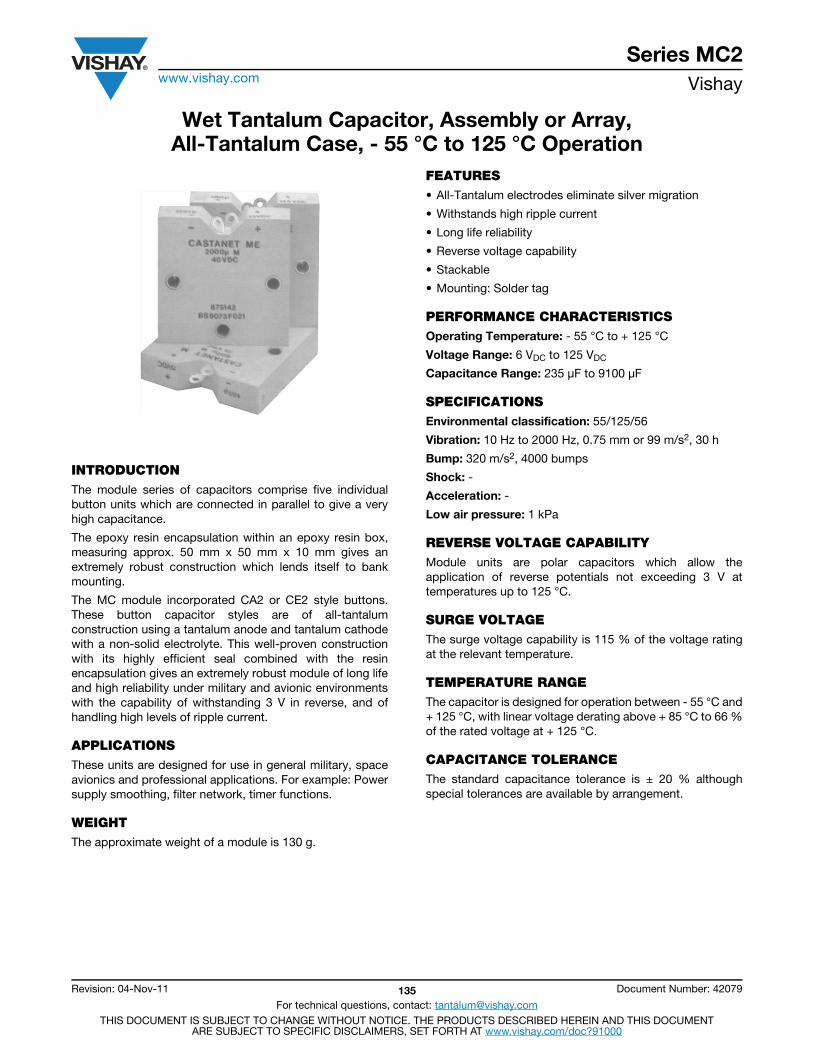
Series MC2www.vishay.com Vishay
Revision: 04-Nov-11 135 Document Number: 42079
For technical questions, contact: [email protected] DOCUMENT IS SUBJECT TO CHANGE WITHOUT NOTICE. THE PRODUCTS DESCRIBED HEREIN AND THIS DOCUMENT
ARE SUBJECT TO SPECIFIC DISCLAIMERS, SET FORTH AT www.vishay.com/doc?91000
Wet Tantalum Capacitor, Assembly or Array,All-Tantalum Case, - 55 °C to 125 °C Operation
INTRODUCTIONThe module series of capacitors comprise five individualbutton units which are connected in parallel to give a veryhigh capacitance.
The epoxy resin encapsulation within an epoxy resin box,measuring approx. 50 mm x 50 mm x 10 mm gives anextremely robust construction which lends itself to bankmounting.
The MC module incorporated CA2 or CE2 style buttons.These button capacitor styles are of all-tantalumconstruction using a tantalum anode and tantalum cathodewith a non-solid electrolyte. This well-proven constructionwith its highly efficient seal combined with the resinencapsulation gives an extremely robust module of long lifeand high reliability under military and avionic environmentswith the capability of withstanding 3 V in reverse, and ofhandling high levels of ripple current.
APPLICATIONSThese units are designed for use in general military, spaceavionics and professional applications. For example: Powersupply smoothing, filter network, timer functions.
WEIGHTThe approximate weight of a module is 130 g.
FEATURES• All-Tantalum electrodes eliminate silver migration
• Withstands high ripple current
• Long life reliability
• Reverse voltage capability
• Stackable
• Mounting: Solder tag
PERFORMANCE CHARACTERISTICSOperating Temperature: - 55 °C to + 125 °C
Voltage Range: 6 VDC to 125 VDC
Capacitance Range: 235 μF to 9100 μF
SPECIFICATIONSEnvironmental classification: 55/125/56
Vibration: 10 Hz to 2000 Hz, 0.75 mm or 99 m/s2, 30 h
Bump: 320 m/s2, 4000 bumps
Shock: -
Acceleration: -
Low air pressure: 1 kPa
REVERSE VOLTAGE CAPABILITYModule units are polar capacitors which allow theapplication of reverse potentials not exceeding 3 V attemperatures up to 125 °C.
SURGE VOLTAGEThe surge voltage capability is 115 % of the voltage ratingat the relevant temperature.
TEMPERATURE RANGEThe capacitor is designed for operation between - 55 °C and+ 125 °C, with linear voltage derating above + 85 °C to 66 %of the rated voltage at + 125 °C.
CAPACITANCE TOLERANCEThe standard capacitance tolerance is ± 20 % althoughspecial tolerances are available by arrangement.
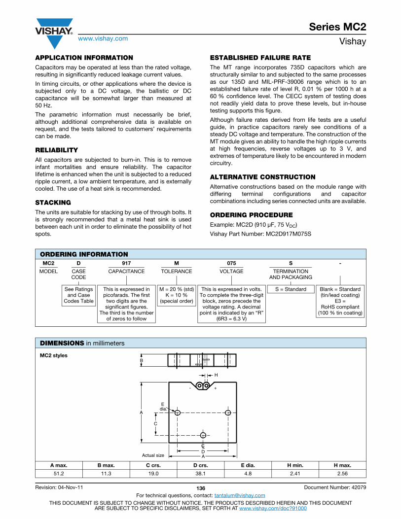
Series MC2www.vishay.com Vishay
Revision: 04-Nov-11 136 Document Number: 42079
For technical questions, contact: [email protected] DOCUMENT IS SUBJECT TO CHANGE WITHOUT NOTICE. THE PRODUCTS DESCRIBED HEREIN AND THIS DOCUMENT
ARE SUBJECT TO SPECIFIC DISCLAIMERS, SET FORTH AT www.vishay.com/doc?91000
APPLICATION INFORMATIONCapacitors may be operated at less than the rated voltage,resulting in significantly reduced leakage current values.
In timing circuits, or other applications where the device issubjected only to a DC voltage, the ballistic or DCcapacitance will be somewhat larger than measured at50 Hz.
The parametric information must necessarily be brief,although additional comprehensive data is available onrequest, and the tests tailored to customers’ requirementscan be made.
RELIABILITYAll capacitors are subjected to burn-in. This is to removeinfant mortalities and ensure reliability. The capacitorlifetime is enhanced when the unit is subjected to a reducedripple current, a low ambient temperature, and is externallycooled. The use of a heat sink is recommended.
STACKINGThe units are suitable for stacking by use of through bolts. Itis strongly recommended that a metal heat sink is usedbetween each unit in order to eliminate the possibility of hotspots.
ESTABLISHED FAILURE RATEThe MT range incorporates 735D capacitors which arestructurally similar to and subjected to the same processesas our 135D and MIL-PRF-39006 range which is to anestablished failure rate of level R, 0.01 % per 1000 h at a60 % confidence level. The CECC system of testing doesnot readily yield data to prove these levels, but in-housetesting supports this figure.
Although failure rates derived from life tests are a usefulguide, in practice capacitors rarely see conditions of asteady DC voltage and temperature. The construction of theMT module gives an ability to handle the high ripple currentsat high frequencies, reverse voltages up to 3 V, andextremes of temperature likely to be encountered in moderncircuitry.
ALTERNATIVE CONSTRUCTIONAlternative constructions based on the module range withdiffering terminal configurations and capacitorcombinations including series connected units are available.
ORDERING PROCEDUREExample: MC2D (910 μF, 75 VDC)
Vishay Part Number: MC2D917M075S
ORDERING INFORMATIONMC2 D 917 M 075 S -
MODEL CASECODE
CAPACITANCE TOLERANCE VOLTAGE TERMINATIONAND PACKAGING
See Ratingsand Case
Codes Table
This is expressed inpicofarads. The first
two digits are thesignificant figures.
The third is the numberof zeros to follow
M = 20 % (std)K = 10 %
(special order)
This is expressed in volts.To complete the three-digitblock, zeros precede thevoltage rating. A decimal
point is indicated by an “R”(6R3 = 6.3 V)
S = Standard Blank = Standard(tin/lead coating)
E3 = RoHS compliant
(100 % tin coating)
DIMENSIONS in millimeters
A max. B max. C crs. D crs. E dia. H min. H max.
51.2 11.3 19.0 38.1 4.8 2.41 2.56
B
H
A
A
CLD
C
E dia.
Actual size
- +
MC2 styles
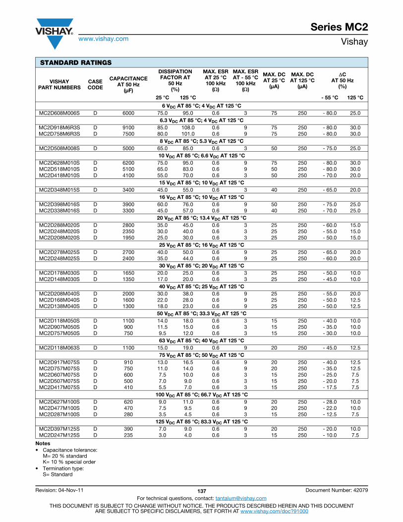
Series MC2www.vishay.com Vishay
Revision: 04-Nov-11 137 Document Number: 42079
For technical questions, contact: [email protected] DOCUMENT IS SUBJECT TO CHANGE WITHOUT NOTICE. THE PRODUCTS DESCRIBED HEREIN AND THIS DOCUMENT
ARE SUBJECT TO SPECIFIC DISCLAIMERS, SET FORTH AT www.vishay.com/doc?91000
Notes• Capacitance tolerance:
M= 20 % standardK= 10 % special order
• Termination type:S= Standard
STANDARD RATINGS
VISHAYPART NUMBERS
CASECODE
CAPACITANCEAT 50 Hz
(μF)
DISSIPATION FACTOR AT
50 Hz(%)
MAX. ESRAT 25 °C100 kHz
()
MAX. ESRAT - 55 °C100 kHz
()
MAX. DCAT 25 °C
(μA)
MAX. DCAT 125 °C
(μA)
CAT 50 Hz
(%)
25 °C 125 °C - 55 °C 125 °C
6 VDC AT 85 °C; 4 VDC AT 125 °CMC2D608M006S D 6000 75.0 95.0 0.6 3 75 250 - 80.0 25.0
6.3 VDC AT 85 °C; 4 VDC AT 125 °CMC2D918M6R3S D 9100 85.0 108.0 0.6 9 75 250 - 80.0 30.0MC2D758M6R3S D 7500 80.0 101.0 0.6 9 75 250 - 80.0 30.0
8 VDC AT 85 °C; 5.3 VDC AT 125 °CMC2D508M008S D 5000 65.0 85.0 0.6 3 50 250 - 75.0 25.0
10 VDC AT 85 °C; 6.6 VDC AT 125 °CMC2D628M010S D 6200 75.0 95.0 0.6 9 75 250 - 80.0 30.0MC2D518M010S D 5100 65.0 83.0 0.6 9 50 250 - 80.0 30.0MC2D418M010S D 4100 55.0 70.0 0.6 3 50 250 - 70.0 20.0
15 VDC AT 85 °C; 10 VDC AT 125 °CMC2D348M015S D 3400 45.0 55.0 0.6 3 40 250 - 65.0 20.0
16 VDC AT 85 °C; 10 VDC AT 125 °CMC2D398M016S D 3900 60.0 76.0 0.6 9 50 250 - 75.0 25.0MC2D338M016S D 3300 45.0 57.0 0.6 9 40 250 - 70.0 25.0
20 VDC AT 85 °C; 13.4 VDC AT 125 °CMC2D288M020S D 2800 35.0 45.0 0.6 3 25 250 - 60.0 15.0MC2D248M020S D 2350 30.0 40.0 0.6 3 25 250 - 55.0 15.0MC2D208M020S D 1950 25.0 30.0 0.6 3 25 250 - 50.0 15.0
25 VDC AT 85 °C; 16 VDC AT 125 °CMC2D278M025S D 2700 40.0 50.0 0.6 9 25 250 - 65.0 20.0MC2D248M025S D 2400 35.0 44.0 0.6 9 25 250 - 60.0 20.0
30 VDC AT 85 °C; 20 VDC AT 125 °CMC2D178M030S D 1650 20.0 25.0 0.6 3 25 250 - 50.0 10.0MC2D148M030S D 1350 17.0 20.0 0.6 3 25 250 - 45.0 10.0
40 VDC AT 85 °C; 25 VDC AT 125 °CMC2D208M040S D 2000 30.0 38.0 0.6 9 25 250 - 55.0 20.0MC2D168M040S D 1600 22.0 28.0 0.6 9 25 250 - 50.0 12.5MC2D138M040S D 1300 18.0 23.0 0.6 9 25 250 - 50.0 12.5
50 VDC AT 85 °C; 33.3 VDC AT 125 °CMC2D118M050S D 1100 14.0 18.0 0.6 3 15 250 - 40.0 10.0MC2D907M050S D 900 11.5 15.0 0.6 3 15 250 - 35.0 10.0MC2D757M050S D 750 9.5 12.0 0.6 3 15 250 - 30.0 10.0
63 VDC AT 85 °C; 40 VDC AT 125 °CMC2D118M063S D 1100 15.0 19.0 0.6 9 20 250 - 45.0 12.5
75 VDC AT 85 °C; 50 VDC AT 125 °CMC2D917M075S D 910 13.0 16.5 0.6 9 20 250 - 40.0 12.5MC2D757M075S D 750 11.0 14.0 0.6 9 20 250 - 35.0 12.5MC2D607M075S D 600 7.5 10.0 0.6 3 15 250 - 25.0 7.5MC2D507M075S D 500 7.0 9.0 0.6 3 15 250 - 20.0 7.5MC2D417M075S D 410 5.5 7.0 0.6 3 15 250 - 17.5 7.5
100 VDC AT 85 °C; 66.7 VDC AT 125 °CMC2D627M100S D 620 9.0 11.0 0.6 9 20 250 - 28.0 10.0MC2D477M100S D 470 7.5 9.5 0.6 9 20 250 - 22.0 10.0MC2D287M100S D 280 3.5 4.5 0.6 3 15 250 - 12.5 7.5
125 VDC AT 85 °C; 83.3 VDC AT 125 °CMC2D397M125S D 390 7.0 9.0 0.6 9 20 250 - 20.0 10.0MC2D247M125S D 235 3.0 4.0 0.6 3 15 250 - 10.0 7.5
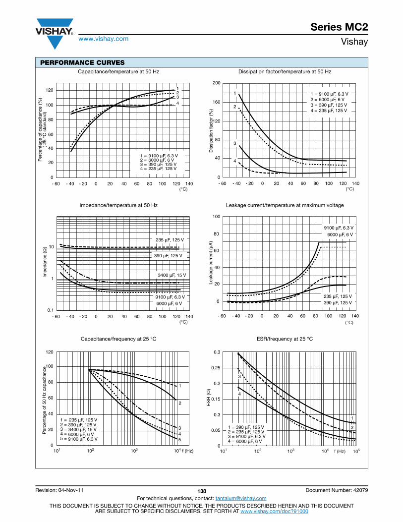
Series MC2www.vishay.com Vishay
Revision: 04-Nov-11 138 Document Number: 42079
For technical questions, contact: [email protected] DOCUMENT IS SUBJECT TO CHANGE WITHOUT NOTICE. THE PRODUCTS DESCRIBED HEREIN AND THIS DOCUMENT
ARE SUBJECT TO SPECIFIC DISCLAIMERS, SET FORTH AT www.vishay.com/doc?91000
PERFORMANCE CURVESCapacitance/temperature at 50 Hz Dissipation factor/temperature at 50 Hz
Impedance/temperature at 50 Hz Leakage current/temperature at maximum voltage
Capacitance/frequency at 25 °C ESR/frequency at 25 °C
Per
cent
age
of c
apac
itanc
e (%
)(
25 °
C s
tand
ard)
120
100
80
60
40
20
- 60 - 40 - 20 0 20 40 60 80 100 120 140 (°C)
1234
9100 µF, 6.3 V 6000 µF, 6 V390 µF, 125 V 235 µF, 125 V
1 =2 =3 =4 =
0
Dis
sipa
tion
fact
or (
%)
200
160
120
80
40
0- 60 - 40 - 20 0 20 40 60 80 100 120 140
(°C)
9100 µF, 6.3 V6000 µF, 6 V 390 µF, 125 V235 µF, 125 V
1 =2 =3 =4 =
1
2
3
4
- 60 - 40 - 20 0 20 40 60 80 100 120 140 (°C)
1
10
0.1
9100 µF, 6.3 V
235 µF, 125 V
390 µF, 125 V
6000 µF, 6 V
3400 µF, 15 V Impe
danc
e (Ω
)
100
80
60
40
20
0
Leak
age
curr
ent (
µA)
- 60 - 40 - 20 0 20 40 60 80 100 120 140 (°C)
9100 µF, 6.3 V
235 µF, 125 V 390 µF, 125 V
6000 µF, 6 V
100
80
60
40
20
0102 103 104101
Per
cent
age
of 5
0 H
z ca
paci
tanc
e
f (Hz)
120
1
2
45
3
1 =2 =3 =4 =5 =
235 µF, 125 V390 µF, 125 V 3400 µF, 15 V 6000 µF, 6 V 9100 µF, 6.3 V
0.3
0.25
0.2
0.15
0.3
0.05
0f (Hz)101 102 103 104 105
ES
R (
Ω)
1 =2 =3 =4 =
235 µF, 125 V390 µF, 125 V
6000 µF, 6 V9100 µF, 6.3 V
1
2
3
4
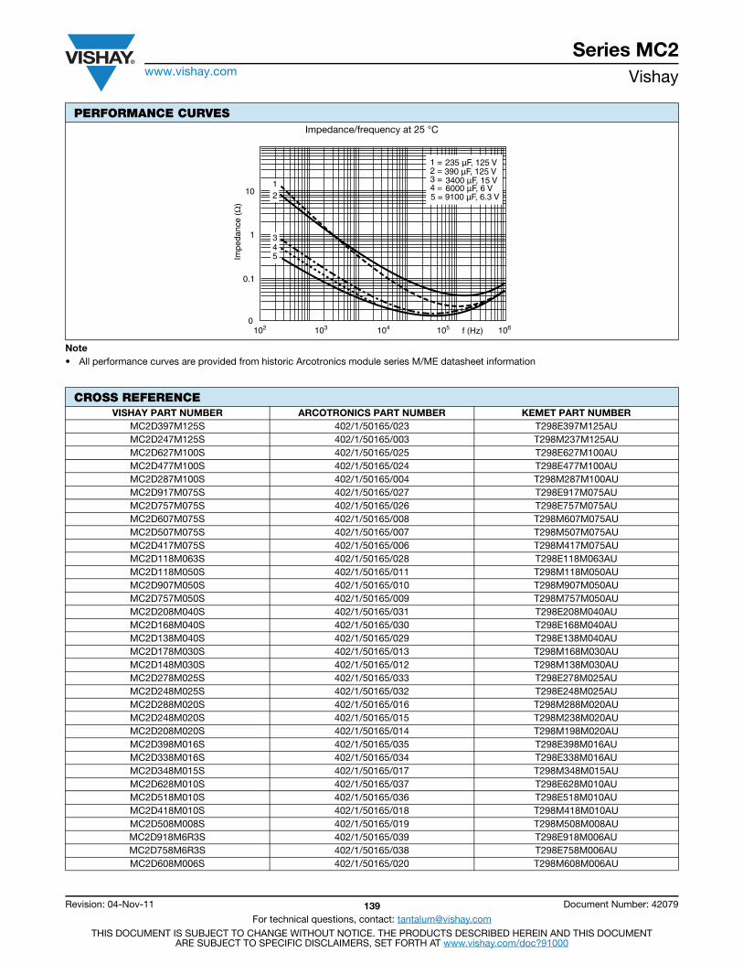
Series MC2www.vishay.com Vishay
Revision: 04-Nov-11 139 Document Number: 42079
For technical questions, contact: [email protected] DOCUMENT IS SUBJECT TO CHANGE WITHOUT NOTICE. THE PRODUCTS DESCRIBED HEREIN AND THIS DOCUMENT
ARE SUBJECT TO SPECIFIC DISCLAIMERS, SET FORTH AT www.vishay.com/doc?91000
Note• All performance curves are provided from historic Arcotronics module series M/ME datasheet information
Impedance/frequency at 25 °C
CROSS REFERENCEVISHAY PART NUMBER ARCOTRONICS PART NUMBER KEMET PART NUMBER
MC2D397M125S 402/1/50165/023 T298E397M125AUMC2D247M125S 402/1/50165/003 T298M237M125AUMC2D627M100S 402/1/50165/025 T298E627M100AUMC2D477M100S 402/1/50165/024 T298E477M100AUMC2D287M100S 402/1/50165/004 T298M287M100AUMC2D917M075S 402/1/50165/027 T298E917M075AUMC2D757M075S 402/1/50165/026 T298E757M075AUMC2D607M075S 402/1/50165/008 T298M607M075AUMC2D507M075S 402/1/50165/007 T298M507M075AUMC2D417M075S 402/1/50165/006 T298M417M075AUMC2D118M063S 402/1/50165/028 T298E118M063AUMC2D118M050S 402/1/50165/011 T298M118M050AUMC2D907M050S 402/1/50165/010 T298M907M050AUMC2D757M050S 402/1/50165/009 T298M757M050AUMC2D208M040S 402/1/50165/031 T298E208M040AUMC2D168M040S 402/1/50165/030 T298E168M040AUMC2D138M040S 402/1/50165/029 T298E138M040AUMC2D178M030S 402/1/50165/013 T298M168M030AUMC2D148M030S 402/1/50165/012 T298M138M030AUMC2D278M025S 402/1/50165/033 T298E278M025AUMC2D248M025S 402/1/50165/032 T298E248M025AUMC2D288M020S 402/1/50165/016 T298M288M020AUMC2D248M020S 402/1/50165/015 T298M238M020AUMC2D208M020S 402/1/50165/014 T298M198M020AUMC2D398M016S 402/1/50165/035 T298E398M016AUMC2D338M016S 402/1/50165/034 T298E338M016AUMC2D348M015S 402/1/50165/017 T298M348M015AUMC2D628M010S 402/1/50165/037 T298E628M010AUMC2D518M010S 402/1/50165/036 T298E518M010AUMC2D418M010S 402/1/50165/018 T298M418M010AUMC2D508M008S 402/1/50165/019 T298M508M008AUMC2D918M6R3S 402/1/50165/039 T298E918M006AUMC2D758M6R3S 402/1/50165/038 T298E758M006AUMC2D608M006S 402/1/50165/020 T298M608M006AU
PERFORMANCE CURVES
0.1
1
10
0f (Hz) 103 102 104 105 106
Impe
danc
e (Ω
)
12
345
1 =2 =3 =4 =
235 µF, 125 V 390 µF, 125 V
6000 µF, 6 V 3400 µF, 15 V
5 = 9100 µF, 6.3 V
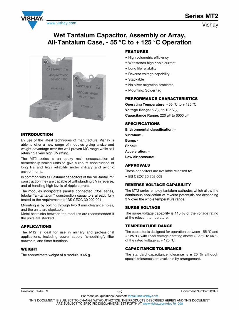
Series MT2www.vishay.com Vishay
Revision: 01-Jul-09 140 Document Number: 42097
For technical questions, contact: [email protected] DOCUMENT IS SUBJECT TO CHANGE WITHOUT NOTICE. THE PRODUCTS DESCRIBED HEREIN AND THIS DOCUMENT
ARE SUBJECT TO SPECIFIC DISCLAIMERS, SET FORTH AT www.vishay.com/doc?91000
Wet Tantalum Capacitor, Assembly or Array,All-Tantalum Case, - 55 °C to + 125 °C Operation
INTRODUCTIONBy use of the latest techniques of manufacture, Vishay isable to offer a new range of modules giving a size andweight advantage over the well proven MC range while stillretaining a very high CV rating.
The MT2 series is an epoxy resin encapsulation ofhermetically sealed units to give a robust construction oflong life and high reliability under military and avionicenvironments.
In common with all Castanet capacitors of the “all-tantalum”construction they are capable of withstanding 3 V in reverse,and of handling high levels of ripple current.
The modules incorporate parallel connected 735D series,tubular “all-tantalum” construction capacitors already fullytested to the requirements of BS CECC 30 202 001.
Mounting is by bolting through two 3 mm clearance holes,and the units are stackable.Metal heatsinks between the modules are recommended ifthe units are stacked.
APPLICATIONSThe MT2 is ideal for use in military and professionalapplications, including power supply “smoothing”, filternetworks, and timer functions.
WEIGHTThe approximate weight of a module is 65 g.
FEATURES• High volumetric efficiency
• Withstands high ripple current
• Long life reliability
• Reverse voltage capability
• Stackable
• No silver migration problems
• Mounting: Solder tag
PERFORMANCE CHARACTERISTICSOperating Temperature: - 55 °C to + 125 °C
Voltage Range: 6 VDC to 125 VDC
Capacitance Range: 220 μF to 6000 μF
SPECIFICATIONSEnvironmental classification: -
Vibration: -
Bump: -
Shock: -
Acceleration: -
Low air pressure: -
APPROVALSThese capacitors are available released to:
• BS CECC 30 202 009
REVERSE VOLTAGE CAPABILITYThe MT2 series employ tantalum cathodes which allow thecontinuous application of reverse potentials not exceeding3 V over the whole temperature range.
SURGE VOLTAGEThe surge voltage capability is 115 % of the voltage ratingat the relevant temperature.
TEMPERATURE RANGEThe capacitor is designed for operation between - 55 °C and+ 125 °C, with linear voltage derating above + 85 °C to 66 %of the rated voltage at + 125 °C.
CAPACITANCE TOLERANCEThe standard capacitance tolerance is ± 20 % althoughspecial tolerances are available by arrangement.
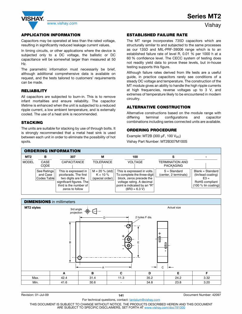
Series MT2www.vishay.com Vishay
Revision: 01-Jul-09 141 Document Number: 42097
For technical questions, contact: [email protected] DOCUMENT IS SUBJECT TO CHANGE WITHOUT NOTICE. THE PRODUCTS DESCRIBED HEREIN AND THIS DOCUMENT
ARE SUBJECT TO SPECIFIC DISCLAIMERS, SET FORTH AT www.vishay.com/doc?91000
APPLICATION INFORMATIONCapacitors may be operated at less than the rated voltage,resulting in significantly reduced leakage current values.
In timing circuits, or other applications where the device issubjected only to a DC voltage, the ballistic or DCcapacitance will be somewhat larger than measured at 50Hz.
The parametric information must necessarily be brief,although additional comprehensive data is available onrequest, and the tests tailored to customers’ requirementscan be made.
RELIABILITYAll capacitors are subjected to burn-in. This is to removeinfant mortalities and ensure reliability. The capacitorlifetime is enhanced when the unit is subjected to a reducedripple current, a low ambient temperature, and is externallycooled. The use of a heat sink is recommended.
STACKINGThe units are suitable for stacking by use of through bolts. Itis strongly recommended that a metal heat sink is usedbetween each unit in order to eliminate the possibility of hotspots.
ESTABLISHED FAILURE RATEThe MT range incorporates 735D capacitors which arestructurally similar to and subjected to the same processesas our 135D and MIL-PRF-39006 range which is to anestablished failure rate of level R, 0.01 % per 1000 h at a60 % confidence level. The CECC system of testing doesnot readily yield data to prove these levels, but in-housetesting supports this figure.
Although failure rates derived from life tests are a usefulguide, in practice capacitors rarely see conditions of asteady DC voltage and temperature. The construction of theMT module gives an ability to handle the high ripple currentsat high frequencies, reverse voltages up to 3 V, andextremes of temperature likely to be encountered in moderncircuitry.
ALTERNATIVE CONSTRUCTIONAlternative constructions based on the module range withdiffering terminal configurations and capacitorcombinations including series connected units are available.
ORDERING PROCEDUREExample: MT2B (300 μF, 100 VDC)
Vishay Part Number: MT2B307M100S
ORDERING INFORMATIONMT2 B 307 M 100 S -
MODEL CASE CODE
CAPACITANCE TOLERANCE VOLTAGE TERMINATION AND PACKAGING
See Ratings and Case
Codes Table
This is expressed in picofarads. The first
two digits are the significant figures. The third is the number of
zeros to follow
M = 20 % (std)K = 10 %
(special order)
This is expressed in volts. To complete the three-digit block, zeros precede the voltage rating. A decimal
point is indicated by an “R” (6R3 = 6.3 V)
S = Standard(center, 2 terminals)
Blank = Standard(tin/lead coating)
E3 = RoHS compliant
(100 % tin coating)
DIMENSIONS in millimeters
A B C D E FMax. 42.4 31.4 11.3 35.2 24.2 3.32Min. 41.6 30.6 - 34.8 23.8 3.20
A
D
C
B E
Actual size
2 holes F dia.
3rd angleprojection
- -
+ +
MT2 styles
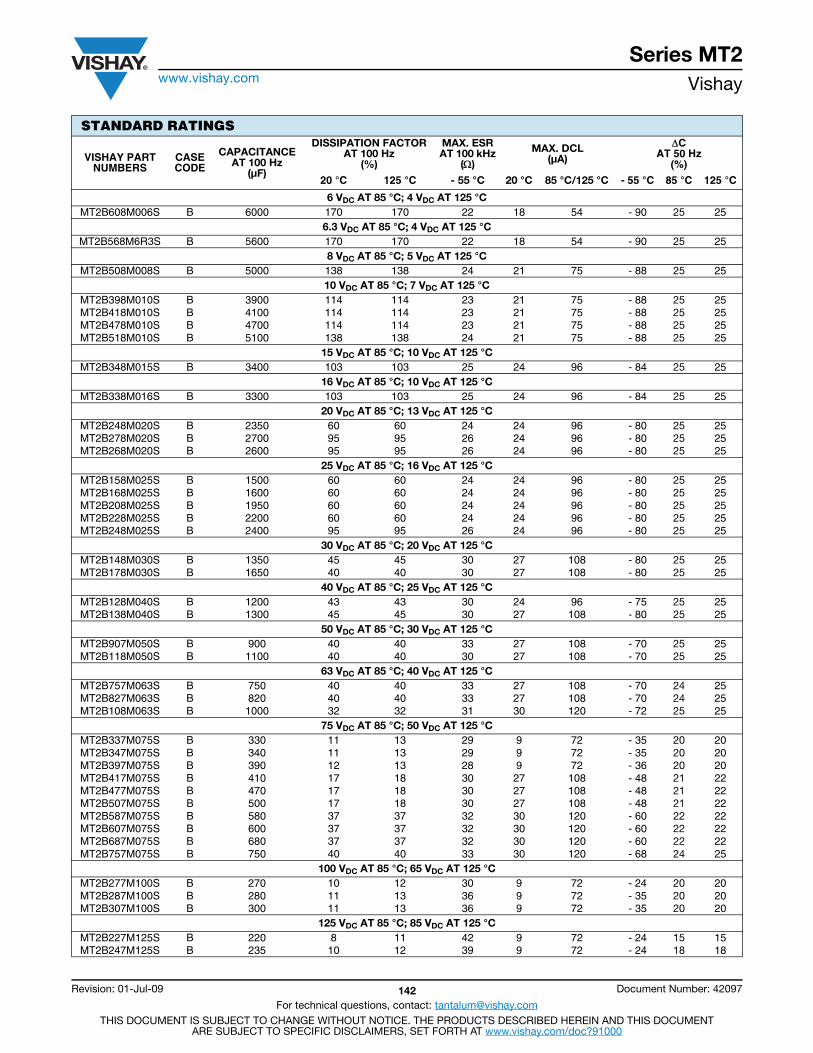
Series MT2www.vishay.com Vishay
Revision: 01-Jul-09 142 Document Number: 42097
For technical questions, contact: [email protected] DOCUMENT IS SUBJECT TO CHANGE WITHOUT NOTICE. THE PRODUCTS DESCRIBED HEREIN AND THIS DOCUMENT
ARE SUBJECT TO SPECIFIC DISCLAIMERS, SET FORTH AT www.vishay.com/doc?91000
STANDARD RATINGS
VISHAY PARTNUMBERS
CASECODE
CAPACITANCEAT 100 Hz
(μF)
DISSIPATION FACTORAT 100 Hz
(%)
MAX. ESRAT 100 kHz
()
MAX. DCL (μA)
CAT 50 Hz
(%)
20 °C 125 °C - 55 °C 20 °C 85 °C/125 °C - 55 °C 85 °C 125 °C
6 VDC AT 85 °C; 4 VDC AT 125 °CMT2B608M006S B 6000 170 170 22 18 54 - 90 25 25
6.3 VDC AT 85 °C; 4 VDC AT 125 °CMT2B568M6R3S B 5600 170 170 22 18 54 - 90 25 25
8 VDC AT 85 °C; 5 VDC AT 125 °CMT2B508M008S B 5000 138 138 24 21 75 - 88 25 25
10 VDC AT 85 °C; 7 VDC AT 125 °CMT2B398M010S B 3900 114 114 23 21 75 - 88 25 25MT2B418M010S B 4100 114 114 23 21 75 - 88 25 25MT2B478M010S B 4700 114 114 23 21 75 - 88 25 25MT2B518M010S B 5100 138 138 24 21 75 - 88 25 25
15 VDC AT 85 °C; 10 VDC AT 125 °CMT2B348M015S B 3400 103 103 25 24 96 - 84 25 25
16 VDC AT 85 °C; 10 VDC AT 125 °CMT2B338M016S B 3300 103 103 25 24 96 - 84 25 25
20 VDC AT 85 °C; 13 VDC AT 125 °CMT2B248M020S B 2350 60 60 24 24 96 - 80 25 25MT2B278M020S B 2700 95 95 26 24 96 - 80 25 25MT2B268M020S B 2600 95 95 26 24 96 - 80 25 25
25 VDC AT 85 °C; 16 VDC AT 125 °CMT2B158M025S B 1500 60 60 24 24 96 - 80 25 25MT2B168M025S B 1600 60 60 24 24 96 - 80 25 25MT2B208M025S B 1950 60 60 24 24 96 - 80 25 25MT2B228M025S B 2200 60 60 24 24 96 - 80 25 25MT2B248M025S B 2400 95 95 26 24 96 - 80 25 25
30 VDC AT 85 °C; 20 VDC AT 125 °CMT2B148M030S B 1350 45 45 30 27 108 - 80 25 25MT2B178M030S B 1650 40 40 30 27 108 - 80 25 25
40 VDC AT 85 °C; 25 VDC AT 125 °CMT2B128M040S B 1200 43 43 30 24 96 - 75 25 25MT2B138M040S B 1300 45 45 30 27 108 - 80 25 25
50 VDC AT 85 °C; 30 VDC AT 125 °CMT2B907M050S B 900 40 40 33 27 108 - 70 25 25MT2B118M050S B 1100 40 40 30 27 108 - 70 25 25
63 VDC AT 85 °C; 40 VDC AT 125 °CMT2B757M063S B 750 40 40 33 27 108 - 70 24 25MT2B827M063S B 820 40 40 33 27 108 - 70 24 25MT2B108M063S B 1000 32 32 31 30 120 - 72 25 25
75 VDC AT 85 °C; 50 VDC AT 125 °CMT2B337M075S B 330 11 13 29 9 72 - 35 20 20MT2B347M075S B 340 11 13 29 9 72 - 35 20 20MT2B397M075S B 390 12 13 28 9 72 - 36 20 20MT2B417M075S B 410 17 18 30 27 108 - 48 21 22MT2B477M075S B 470 17 18 30 27 108 - 48 21 22MT2B507M075S B 500 17 18 30 27 108 - 48 21 22MT2B587M075S B 580 37 37 32 30 120 - 60 22 22MT2B607M075S B 600 37 37 32 30 120 - 60 22 22MT2B687M075S B 680 37 37 32 30 120 - 60 22 22MT2B757M075S B 750 40 40 33 30 120 - 68 24 25
100 VDC AT 85 °C; 65 VDC AT 125 °CMT2B277M100S B 270 10 12 30 9 72 - 24 20 20MT2B287M100S B 280 11 13 36 9 72 - 35 20 20MT2B307M100S B 300 11 13 36 9 72 - 35 20 20
125 VDC AT 85 °C; 85 VDC AT 125 °CMT2B227M125S B 220 8 11 42 9 72 - 24 15 15MT2B247M125S B 235 10 12 39 9 72 - 24 18 18
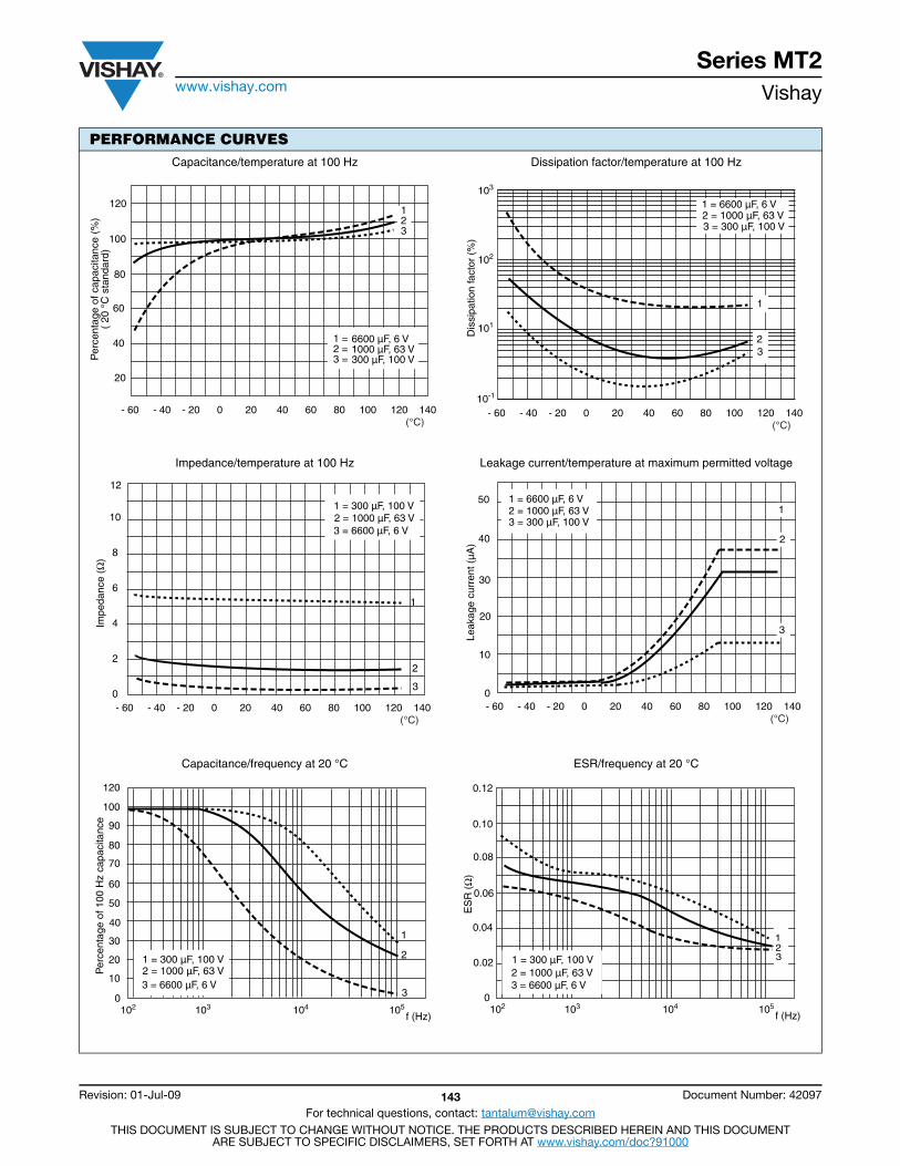
Series MT2www.vishay.com Vishay
Revision: 01-Jul-09 143 Document Number: 42097
For technical questions, contact: [email protected] DOCUMENT IS SUBJECT TO CHANGE WITHOUT NOTICE. THE PRODUCTS DESCRIBED HEREIN AND THIS DOCUMENT
ARE SUBJECT TO SPECIFIC DISCLAIMERS, SET FORTH AT www.vishay.com/doc?91000
PERFORMANCE CURVESCapacitance/temperature at 100 Hz Dissipation factor/temperature at 100 Hz
Impedance/temperature at 100 Hz Leakage current/temperature at maximum permitted voltage
Capacitance/frequency at 20 °C ESR/frequency at 20 °C
Per
cent
age
of c
apac
itanc
e (%
)(
20 °
C s
tand
ard)
120
100
80
60
40
20
- 60 - 40 - 20 0 20 40 60 80 100 120 140 (°C)
6600 µF, 6 V 1000 µF, 63 V 300 µF, 100 V
1 =2 =3 =
123
Dis
sipa
tion
fact
or (
%)
- 60 - 40 - 20 0 20 40 60 80 100 120 140 (°C)
101
102
103
10-1
1
23
3 = 300 µF, 100 V2 = 1000 µF, 63 V1 = 6600 µF, 6 V
10
8
6
4
2
0
12
1
2
3
Impe
danc
e (Ω
)
- 60 - 40 - 20 0 20 40 60 80 100 120 140 (°C)
1 = 300 µF, 100 V 2 = 1000 µF, 63 V 3 = 6600 µF, 6 V
- 60 - 40 - 20 0 20 40 60 80 100 120 140 (°C)
50
40
30
20
10
0
Leak
age
curr
ent (
µA)
1 = 6600 µF, 6 V2 = 1000 µF, 63 V3 = 300 µF, 100 V
11
2
3
103 104 105102
Per
cent
age
of 1
00 H
z ca
paci
tanc
e
f (Hz)
1
2
3
50
60
70
80
90
120
100
40
30
20
10
0
1 = 300 µF, 100 V2 = 1000 µF, 63 V3 = 6600 µF, 6 V
103 104 105102f (Hz)
0.06
0.08
0.10
0.12
0.04
0.02
0
123
ES
R (
Ω)
1 = 300 µF, 100 V2 = 1000 µF, 63 V3 = 6600 µF, 6 V
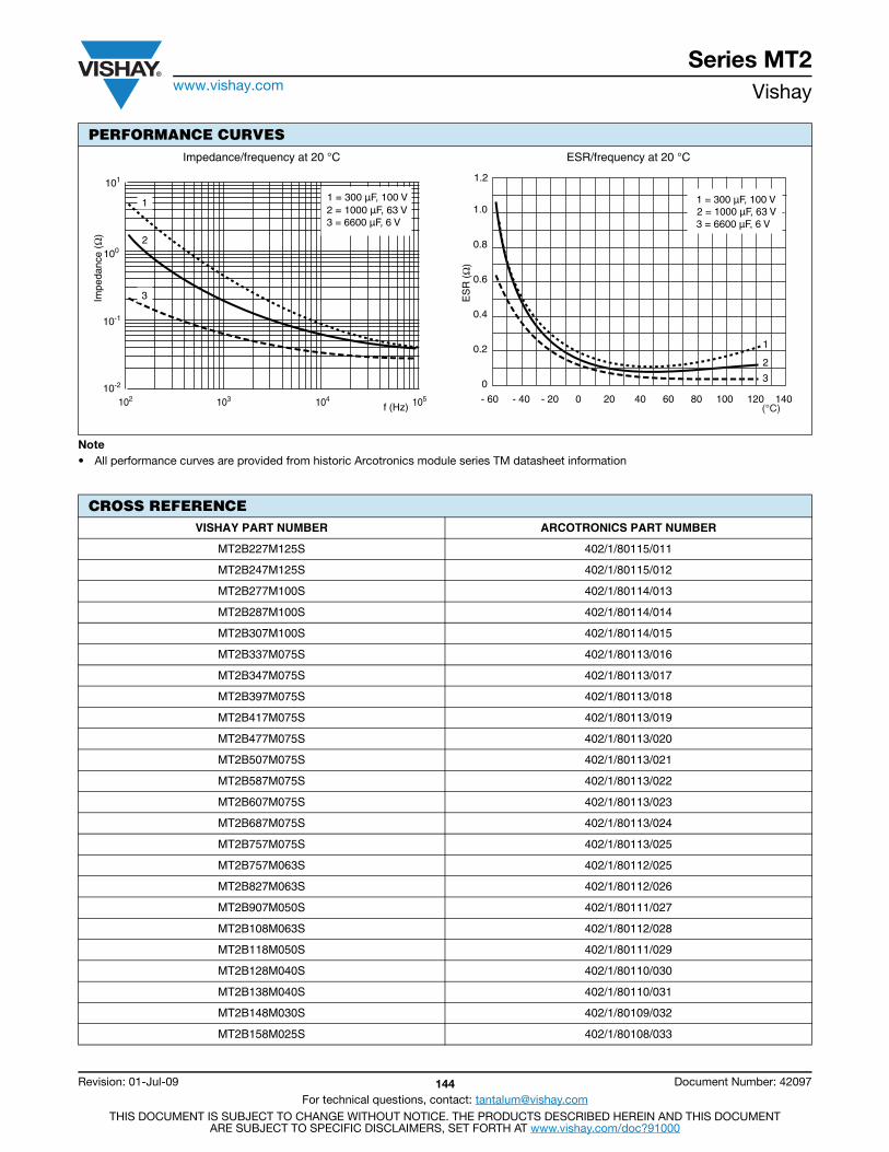
Series MT2www.vishay.com Vishay
Revision: 01-Jul-09 144 Document Number: 42097
For technical questions, contact: [email protected] DOCUMENT IS SUBJECT TO CHANGE WITHOUT NOTICE. THE PRODUCTS DESCRIBED HEREIN AND THIS DOCUMENT
ARE SUBJECT TO SPECIFIC DISCLAIMERS, SET FORTH AT www.vishay.com/doc?91000
Note• All performance curves are provided from historic Arcotronics module series TM datasheet information
Impedance/frequency at 20 °C ESR/frequency at 20 °C
CROSS REFERENCEVISHAY PART NUMBER ARCOTRONICS PART NUMBER
MT2B227M125S 402/1/80115/011
MT2B247M125S 402/1/80115/012
MT2B277M100S 402/1/80114/013
MT2B287M100S 402/1/80114/014
MT2B307M100S 402/1/80114/015
MT2B337M075S 402/1/80113/016
MT2B347M075S 402/1/80113/017
MT2B397M075S 402/1/80113/018
MT2B417M075S 402/1/80113/019
MT2B477M075S 402/1/80113/020
MT2B507M075S 402/1/80113/021
MT2B587M075S 402/1/80113/022
MT2B607M075S 402/1/80113/023
MT2B687M075S 402/1/80113/024
MT2B757M075S 402/1/80113/025
MT2B757M063S 402/1/80112/025
MT2B827M063S 402/1/80112/026
MT2B907M050S 402/1/80111/027
MT2B108M063S 402/1/80112/028
MT2B118M050S 402/1/80111/029
MT2B128M040S 402/1/80110/030
MT2B138M040S 402/1/80110/031
MT2B148M030S 402/1/80109/032
MT2B158M025S 402/1/80108/033
PERFORMANCE CURVES
Impe
danc
e (Ω
)
100
10-1
10-2
101
f (Hz) 103 102 104 105
1 = 300 µF, 100 V2 = 1000 µF, 63 V3 = 6600 µF, 6 V
11
2
3
1.0
0.8
0.6
0.4
0.2
0
1.2
1
2
3
- 60 - 40 - 20 0 20 40 60 80 100 120 140 (°C)
1 = 300 µF, 100 V 2 = 1000 µF, 63 V 3 = 6600 µF, 6 V
ES
R (
Ω)
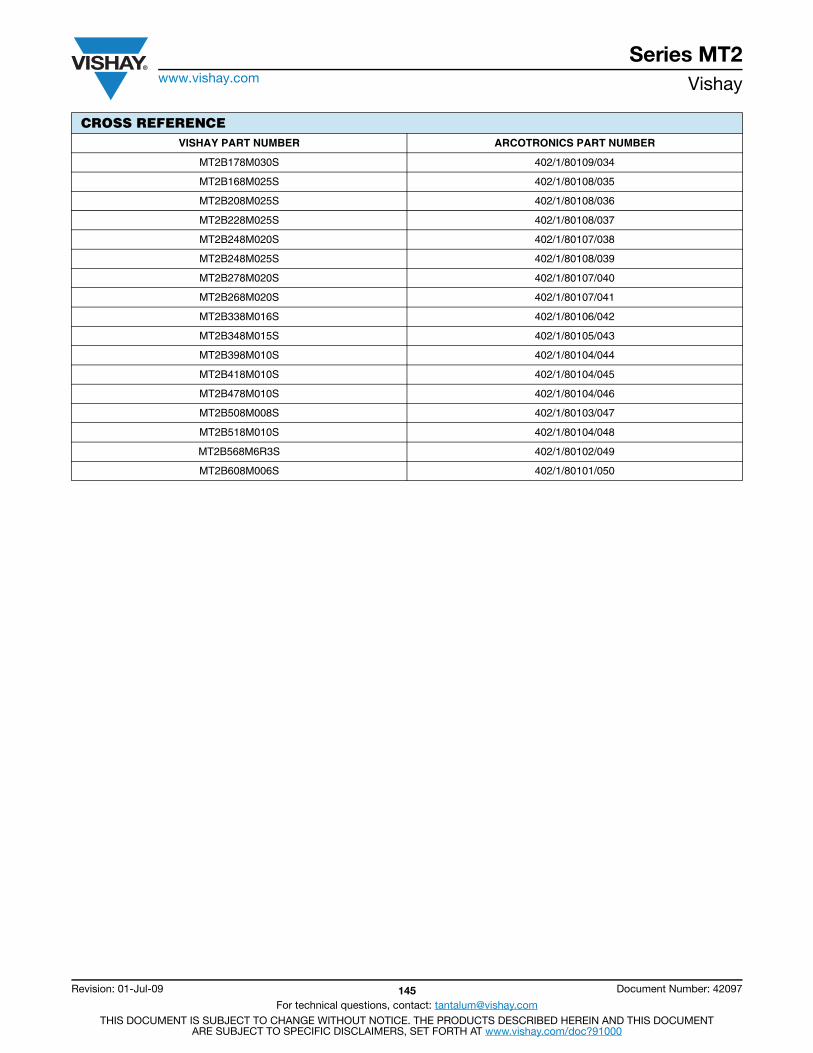
Series MT2www.vishay.com Vishay
Revision: 01-Jul-09 145 Document Number: 42097
For technical questions, contact: [email protected] DOCUMENT IS SUBJECT TO CHANGE WITHOUT NOTICE. THE PRODUCTS DESCRIBED HEREIN AND THIS DOCUMENT
ARE SUBJECT TO SPECIFIC DISCLAIMERS, SET FORTH AT www.vishay.com/doc?91000
MT2B178M030S 402/1/80109/034
MT2B168M025S 402/1/80108/035
MT2B208M025S 402/1/80108/036
MT2B228M025S 402/1/80108/037
MT2B248M020S 402/1/80107/038
MT2B248M025S 402/1/80108/039
MT2B278M020S 402/1/80107/040
MT2B268M020S 402/1/80107/041
MT2B338M016S 402/1/80106/042
MT2B348M015S 402/1/80105/043
MT2B398M010S 402/1/80104/044
MT2B418M010S 402/1/80104/045
MT2B478M010S 402/1/80104/046
MT2B508M008S 402/1/80103/047
MT2B518M010S 402/1/80104/048
MT2B568M6R3S 402/1/80102/049
MT2B608M006S 402/1/80101/050
CROSS REFERENCEVISHAY PART NUMBER ARCOTRONICS PART NUMBER
Contents
CA2.................................147
CE2.................................152
CH2.................................157
CS2.................................162Tantalum
CaseButton
Capacitor

Series CA2www.vishay.com Vishay
Revision: 28-Oct-11 147 Document Number: 42078
For technical questions, contact: [email protected] DOCUMENT IS SUBJECT TO CHANGE WITHOUT NOTICE. THE PRODUCTS DESCRIBED HEREIN AND THIS DOCUMENT
ARE SUBJECT TO SPECIFIC DISCLAIMERS, SET FORTH AT www.vishay.com/doc?91000
Wet Tantalum Capacitor, Button,All-Tantalum Case, - 55 °C to + 125 °C Operation
INTRODUCTIONThis conveniently-packaged polar button unit employs anon-solid electrolyte, and has a sintered tantalum anode.The anode is produced from a high capacitance powderresulting in a capacitor of small size and large CV product.The cathode is also of tantalum and overcomes therestrictions of a silver cathode system in allowing a highripple current rating and application of a 3 V reversepotential. This all-tantalum construction results in anon-catastrophic wear-out mechanism.The seal is a high efficient system comprising a PTFE gasketclamped between coined plates of tantalum by awork-hardened nickel ring. This type of seal, common to allbutton styles, is largely responsible for their long life andhigh reliability and severe military environments.The CA2 series ranges are available in several terminationoptions. These include a mounting stud and pins for circuitmounting.
APPLICATIONSThe CA2 series are designed for use in general military andprofessional applications. For example: Power supply“smoothing” filter networks, switching, by-pass, timerfunctions and where reverse potentials occur.
WEIGHTThe CA2 style with a stud termination weighs approximately18.1 g, including the nut. The CA2 styles, which has a printedcircuit board mounting, weighs approximately 17.3 g.
FEATURES• All-Tantalum electrodes eliminate silver migration• Withstands high ripple current• Long life reliability• Reverse voltage capability• Instant use after long storage• Mounting: Through-hole
PERFORMANCE CHARACTERISTICSOperating Temperature: - 55 °C to + 125 °C Voltage Range: 6 VDC to 125 VDC Capacitance Range: 47 μF to 1800 μF
SPECIFICATIONSEnvironmental classification: 55/125/56Vibration: 10 Hz to 2000 Hz, 0.75 mm or 98 m/s2, 15 hBump: 390 m/s2, 4000 bumpsShock: 981 m/s2
Acceleration: 981 m/s2
Low air pressure: 1 kPa
APPROVALSThese capacitors are available released to:• BS CECC 30 202 002
RIPPLE CURRENT CAPABILITYThe maximum allowable ripple current is 1 ARMS up to 85 °Cand 750 mARMS to 125 °C. These values apply under normalcooling conditions and are irrespective of frequency orwaveform. The algebraic sum of the AC peak and DCvoltages must not exceed the forward or reverse voltageratings at the relevant temperature.At certain frequency/temperature/DC voltage combinationshigher levels of ripple current may be used. Theapplications department should be contacted before theabove levels are exceeded.
REVERSE VOLTAGE CAPABILITYThe CA2 series employ tantalum cathodes which allow thecontinuous application of reverse potentials not exceeding3 V over the whole temperature range.
SURGE VOLTAGEThe surge voltage capability is 115 % of the voltage ratingat the relevant temperature.
TEMPERATURE RANGEThe capacitor is designed for operation between - 55 °C and+ 125 °C, with linear voltage derating above + 85 °C to 66 %of the rated voltage at + 125 °C.
CAPACITANCE TOLERANCEThe standard capacitance tolerance is ± 20 % althoughspecial tolerances are available by arrangement.

Series CA2www.vishay.com Vishay
Revision: 28-Oct-11 148 Document Number: 42078
For technical questions, contact: [email protected] DOCUMENT IS SUBJECT TO CHANGE WITHOUT NOTICE. THE PRODUCTS DESCRIBED HEREIN AND THIS DOCUMENT
ARE SUBJECT TO SPECIFIC DISCLAIMERS, SET FORTH AT www.vishay.com/doc?91000
APPLICATION INFORMATIONCapacitors may be operated at less than the rated voltage,resulting in significantly reduced leakage current values.
In timing circuits, or other applications where the device issubjected only to a DC voltage, the ballistic or DCcapacitance will be somewhat larger than measured at 50 Hz.
The parametric information must necessarily be brief,although additional comprehensive data is available onrequest, and the tests tailored to customers’ requirementscan be made.
RELIABILITYAll capacitors are subjected to burn-in. This is to removeinfant mortalities and ensure reliability. The capacitorlifetime is enhanced when the unit is subjected to a reducedripple current, a low ambient temperature, and is externallycooled. The use of a heat sink is recommended.
ORDERING PROCEDUREExample: CA2C (220 μF, 50 VDC)
Vishay Part Number: CA2C227M050P
Notes• All dimensions are in mm, and are maximum unless otherwise stated(1) For B case size, case height is 6.7 mm(2) Width of anode tag 4.22 mm max.
ORDERING INFORMATIONCA2 C 227 M 100 A -
MODEL CASE CODE
CAPACITANCE TOLERANCE VOLTAGE TERMINATION ANDPACKAGING
See Ratingsand Case
Codes Table
This is expressed inpicofarads. The first
two digits are thesignificant figures.
The third is the number of zeros
to follow
M = 20 % (std)K = 10 %
(special order)
This is expressed in volts.To complete the three-digitblock, zeros precede thevoltage rating. A decimal
point is indicated by an “R”(6R3 = 6.3 V)
A = StudB = PC mount pins
C = Twin tag or ribbonD = Panel or potting tag
Blank = Standard(tin/lead coating)
DIMENSIONS in millimetersThe CA2 series is comprised of two case sizes, differing in depth of cup only. The case size dimensions are shown in the table. Four mounting styles are available in both case sizes.
A B max. C D E F G H J K
crs.L
crs.M
dia.N
nom. P Qdia. R S T
dia.U
crs.V
dia.W
nom.
3.6 8.5 (1) 21.8 8.4 (2) 8.4 16.2 8.4 1.8 0.8 20.3 10.2 1.1 2.4 13.1 1.0 7.5 10.7 1.6 13.0 3.5 0.30
E
F
4 BA shakeproof nut
AB
D
-
+
G
H20 S.W.G.H.T.D. Nickel
Mounting holes M dia.
J
L crs.
Kcrs.
-
+ +
-NHole Q dia.
This mounting style is suitable for panel thickness of up to 1.2 mm
+
-SR
WP
Ucrs.
Hole T dia. Mounting holes V dia.
Stud PC Pins Potting Tag Twin Tag or RibbonsC

Series CA2www.vishay.com Vishay
Revision: 28-Oct-11 149 Document Number: 42078
For technical questions, contact: [email protected] DOCUMENT IS SUBJECT TO CHANGE WITHOUT NOTICE. THE PRODUCTS DESCRIBED HEREIN AND THIS DOCUMENT
ARE SUBJECT TO SPECIFIC DISCLAIMERS, SET FORTH AT www.vishay.com/doc?91000
Note• Part number definitions:
(1) Capacitance tolerance: M= 20 % standard, K = 10 % special order(2) Termination type: A = Stud or bolt, B = Pins for PCB, C = Twin tags or ribbons, D = Potting tag
STANDARD RATINGS
VISHAYPART NUMBERS
CASECODE
CAPACITANCEAT 50 Hz
(μF)
DISSIPATION FACTORAT 50 Hz
(%)
MAX. ESRAT 20 °C100 kHz
()
MAX. ESRAT - 55 °C100 kHz
()
MAX. DCAT 20 °C
(μA)
MAX. DCAT 125 °C
(μA)
CAT 50 Hz
(%)
20 °C 125 °C - 55 °C 125 °C
6 VDC AT 85 °C; 4 VDC AT 125 °C
CA2C128(1)006(2) C 1200 75.0 95.0 1.0 5.0 15.0 50 - 80 25.0
8 VDC AT 85 °C; 5.3 VDC AT 125 °C
CA2C108(1)008(2) C 1000 65.0 85.0 1.0 5.0 10.0 50 - 75 25.0
10 VDC AT 85 °C; 6.6 VDC AT 125 °C
CA2C827(1)010(2) C 820 55.0 70.0 1.0 5.0 10.0 50 - 70 20.0
15 VDC AT 85 °C; 10 VDC AT 125 °C
CA2C687(1)015(2) C 680 45.0 55.0 1.0 5.0 8.0 50 - 65 20.0
20 VDC AT 85 °C; 13.4 VDC AT 125 °C
CA2C397(1)020(2) C 390 25.0 30.0 1.0 5.0 5.0 50 - 50 15.0
CA2C477(1)020(2) C 470 30.0 40.0 1.0 5.0 5.0 50 - 55 15.0
CA2C567(1)020(2) C 560 35.0 45.0 1.0 5.0 5.0 50 - 60 15.0
30 VDC AT 85 °C; 20 VDC AT 125 °C
CA2C277(1)030(2) C 270 17.0 20.0 1.0 5.0 5.0 50 - 45 10.0
CA2C337(1)030(2) C 330 20.0 25.0 1.0 5.0 5.0 50 - 50 10.0
50 VDC AT 85 °C; 33.3 VDC AT 125 °C
CA2C157(1)050(2) C 150 9.5 12.0 1.0 5.0 3.0 50 - 30 10.0
CA2C187(1)050(2) C 180 1.5 15.0 1.0 5.0 3.0 50 - 35 10.0
CA2C227(1)050(2) C 220 14.0 18.0 1.0 5.0 3.0 50 - 40 10.0
75 VDC AT 85 °C; 50 VDC AT 125 °C
CA2C686(1)075(2) C 68 5.0 6.5 1.0 5.0 3.0 50 - 15.0 7.5
CA2C826(1)075(2) C 82 5.5 7.0 1.0 5.0 3.0 50 - 17.5 7.5
CA2C107(1)075(2) C 100 7.0 9.0 1.0 5.0 3.0 50 - 20 7.5
CA2C127(1)075(2) C 120 7.5 10.0 1.0 5.0 3.0 50 - 25 7.5
100 VDC AT 85 °C; 66.7 VDC AT 125 °C
CA2C566(1)100(2) C 56 3.5 4.5 1.0 5.0 3.0 50 - 12.5 7.5
125 VDC AT 85 °C; 83.3 VDC AT 125 °C
CA2C476(1)125(2) C 47 3.0 4.0 1.0 5.0 3.0 50 - 10.0 7.5
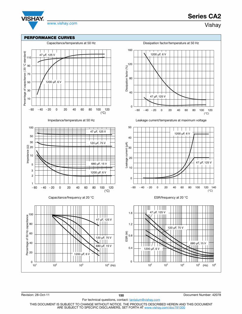
Series CA2www.vishay.com Vishay
Revision: 28-Oct-11 150 Document Number: 42078
For technical questions, contact: [email protected] DOCUMENT IS SUBJECT TO CHANGE WITHOUT NOTICE. THE PRODUCTS DESCRIBED HEREIN AND THIS DOCUMENT
ARE SUBJECT TO SPECIFIC DISCLAIMERS, SET FORTH AT www.vishay.com/doc?91000
PERFORMANCE CURVESCapacitance/temperature at 50 Hz Dissipation factor/temperature at 50 Hz
Impedance/temperature at 50 Hz Leakage current/temperature at maximum voltage
Capacitance/frequency at 20 °C ESR/frequency at 20 °C
110
90
70
50
30
10
(°C)- 60 - 40 - 20 0 20 40 60 80 100 120
Per
cent
age
of c
apac
itanc
e (
20 °
C s
tand
ard)
47 µF, 125 V
1200 µF, 6 V
- 60 - 40 - 20 0 20 40 60 80 100 120
160
120
80
40
0
(°C)
47 µF, 125 V
1200 µF, 6 V
Dis
sipa
tion
fact
or (
%)
100
50
30
20
10
1
2
3
5
Impe
danc
e (Ω
)
(°C)- 60 - 40 - 20 0 20 40 60 80 100 120
47 µF, 125 V
120 µF, 75 V
680 µF, 15 V
1200 µF, 6 V
- 60 - 40 - 20 0 20 40 60 80 100 120 140
50
40
30
20
10
0
(°C)
Leak
age
curr
ent (
µA)
47 µF, 125 V
1200 µF, 6 V
100
80
60
40
20
0102 103 104101
47 µF, 125 V
120 µF, 75 V
1200 µF, 6 V
680 µF, 15 V
Per
cent
age
of 5
0 H
z ca
paci
tanc
e
(Hz) (Hz) 103 102 104 105 1060
0.4
0.8
1.2
1.6 47 µF, 125 V
120 µF, 75 V
1200 µF, 6 V
680 µF, 15 V
ES
R (W
)
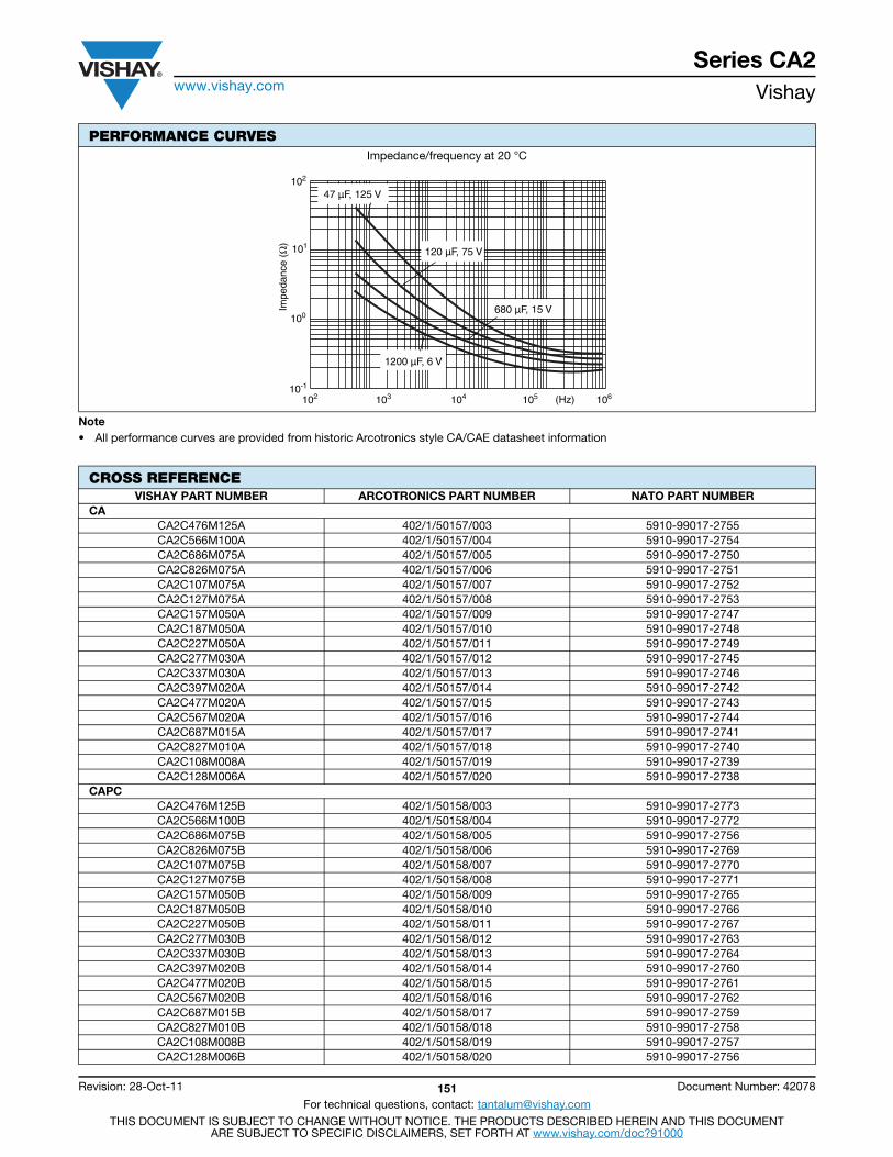
Series CA2www.vishay.com Vishay
Revision: 28-Oct-11 151 Document Number: 42078
For technical questions, contact: [email protected] DOCUMENT IS SUBJECT TO CHANGE WITHOUT NOTICE. THE PRODUCTS DESCRIBED HEREIN AND THIS DOCUMENT
ARE SUBJECT TO SPECIFIC DISCLAIMERS, SET FORTH AT www.vishay.com/doc?91000
Note• All performance curves are provided from historic Arcotronics style CA/CAE datasheet information
Impedance/frequency at 20 °C
CROSS REFERENCEVISHAY PART NUMBER ARCOTRONICS PART NUMBER NATO PART NUMBER
CACA2C476M125A 402/1/50157/003 5910-99017-2755CA2C566M100A 402/1/50157/004 5910-99017-2754CA2C686M075A 402/1/50157/005 5910-99017-2750CA2C826M075A 402/1/50157/006 5910-99017-2751CA2C107M075A 402/1/50157/007 5910-99017-2752CA2C127M075A 402/1/50157/008 5910-99017-2753CA2C157M050A 402/1/50157/009 5910-99017-2747CA2C187M050A 402/1/50157/010 5910-99017-2748CA2C227M050A 402/1/50157/011 5910-99017-2749CA2C277M030A 402/1/50157/012 5910-99017-2745CA2C337M030A 402/1/50157/013 5910-99017-2746CA2C397M020A 402/1/50157/014 5910-99017-2742CA2C477M020A 402/1/50157/015 5910-99017-2743CA2C567M020A 402/1/50157/016 5910-99017-2744CA2C687M015A 402/1/50157/017 5910-99017-2741CA2C827M010A 402/1/50157/018 5910-99017-2740CA2C108M008A 402/1/50157/019 5910-99017-2739CA2C128M006A 402/1/50157/020 5910-99017-2738
CAPCCA2C476M125B 402/1/50158/003 5910-99017-2773CA2C566M100B 402/1/50158/004 5910-99017-2772CA2C686M075B 402/1/50158/005 5910-99017-2756CA2C826M075B 402/1/50158/006 5910-99017-2769CA2C107M075B 402/1/50158/007 5910-99017-2770CA2C127M075B 402/1/50158/008 5910-99017-2771CA2C157M050B 402/1/50158/009 5910-99017-2765CA2C187M050B 402/1/50158/010 5910-99017-2766CA2C227M050B 402/1/50158/011 5910-99017-2767CA2C277M030B 402/1/50158/012 5910-99017-2763CA2C337M030B 402/1/50158/013 5910-99017-2764CA2C397M020B 402/1/50158/014 5910-99017-2760CA2C477M020B 402/1/50158/015 5910-99017-2761CA2C567M020B 402/1/50158/016 5910-99017-2762CA2C687M015B 402/1/50158/017 5910-99017-2759CA2C827M010B 402/1/50158/018 5910-99017-2758CA2C108M008B 402/1/50158/019 5910-99017-2757CA2C128M006B 402/1/50158/020 5910-99017-2756
PERFORMANCE CURVES
Impe
danc
e (Ω
)
102
101
100
10-1
(Hz) 103 102 104 105 106
47 µF, 125 V
120 µF, 75 V
1200 µF, 6 V
680 µF, 15 V
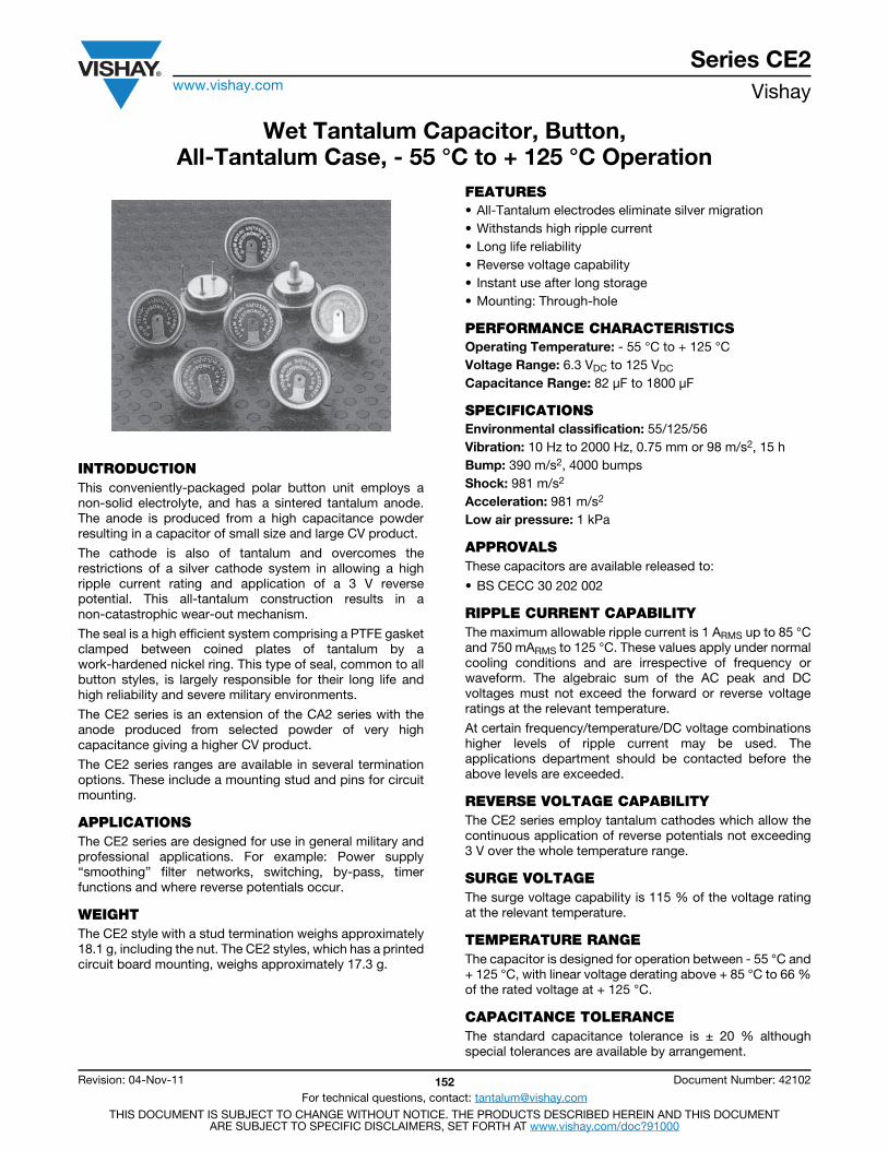
Series CE2www.vishay.com Vishay
Revision: 04-Nov-11 152 Document Number: 42102
For technical questions, contact: [email protected] DOCUMENT IS SUBJECT TO CHANGE WITHOUT NOTICE. THE PRODUCTS DESCRIBED HEREIN AND THIS DOCUMENT
ARE SUBJECT TO SPECIFIC DISCLAIMERS, SET FORTH AT www.vishay.com/doc?91000
Wet Tantalum Capacitor, Button,All-Tantalum Case, - 55 °C to + 125 °C Operation
INTRODUCTIONThis conveniently-packaged polar button unit employs anon-solid electrolyte, and has a sintered tantalum anode.The anode is produced from a high capacitance powderresulting in a capacitor of small size and large CV product.
The cathode is also of tantalum and overcomes therestrictions of a silver cathode system in allowing a highripple current rating and application of a 3 V reversepotential. This all-tantalum construction results in anon-catastrophic wear-out mechanism.
The seal is a high efficient system comprising a PTFE gasketclamped between coined plates of tantalum by awork-hardened nickel ring. This type of seal, common to allbutton styles, is largely responsible for their long life andhigh reliability and severe military environments.
The CE2 series is an extension of the CA2 series with theanode produced from selected powder of very highcapacitance giving a higher CV product.
The CE2 series ranges are available in several terminationoptions. These include a mounting stud and pins for circuitmounting.
APPLICATIONSThe CE2 series are designed for use in general military andprofessional applications. For example: Power supply“smoothing” filter networks, switching, by-pass, timerfunctions and where reverse potentials occur.
WEIGHTThe CE2 style with a stud termination weighs approximately18.1 g, including the nut. The CE2 styles, which has a printedcircuit board mounting, weighs approximately 17.3 g.
FEATURES• All-Tantalum electrodes eliminate silver migration• Withstands high ripple current• Long life reliability• Reverse voltage capability• Instant use after long storage• Mounting: Through-hole
PERFORMANCE CHARACTERISTICSOperating Temperature: - 55 °C to + 125 °C Voltage Range: 6.3 VDC to 125 VDC Capacitance Range: 82 μF to 1800 μF
SPECIFICATIONSEnvironmental classification: 55/125/56Vibration: 10 Hz to 2000 Hz, 0.75 mm or 98 m/s2, 15 hBump: 390 m/s2, 4000 bumpsShock: 981 m/s2
Acceleration: 981 m/s2
Low air pressure: 1 kPa
APPROVALSThese capacitors are available released to:
• BS CECC 30 202 002
RIPPLE CURRENT CAPABILITYThe maximum allowable ripple current is 1 ARMS up to 85 °Cand 750 mARMS to 125 °C. These values apply under normalcooling conditions and are irrespective of frequency orwaveform. The algebraic sum of the AC peak and DCvoltages must not exceed the forward or reverse voltageratings at the relevant temperature.
At certain frequency/temperature/DC voltage combinationshigher levels of ripple current may be used. Theapplications department should be contacted before theabove levels are exceeded.
REVERSE VOLTAGE CAPABILITYThe CE2 series employ tantalum cathodes which allow thecontinuous application of reverse potentials not exceeding3 V over the whole temperature range.
SURGE VOLTAGEThe surge voltage capability is 115 % of the voltage ratingat the relevant temperature.
TEMPERATURE RANGEThe capacitor is designed for operation between - 55 °C and+ 125 °C, with linear voltage derating above + 85 °C to 66 %of the rated voltage at + 125 °C.
CAPACITANCE TOLERANCEThe standard capacitance tolerance is ± 20 % althoughspecial tolerances are available by arrangement.
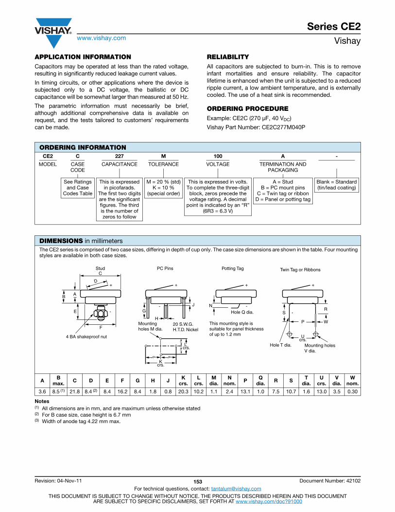
Series CE2www.vishay.com Vishay
Revision: 04-Nov-11 153 Document Number: 42102
For technical questions, contact: [email protected] DOCUMENT IS SUBJECT TO CHANGE WITHOUT NOTICE. THE PRODUCTS DESCRIBED HEREIN AND THIS DOCUMENT
ARE SUBJECT TO SPECIFIC DISCLAIMERS, SET FORTH AT www.vishay.com/doc?91000
APPLICATION INFORMATIONCapacitors may be operated at less than the rated voltage,resulting in significantly reduced leakage current values.
In timing circuits, or other applications where the device issubjected only to a DC voltage, the ballistic or DCcapacitance will be somewhat larger than measured at 50 Hz.
The parametric information must necessarily be brief,although additional comprehensive data is available onrequest, and the tests tailored to customers’ requirementscan be made.
RELIABILITYAll capacitors are subjected to burn-in. This is to removeinfant mortalities and ensure reliability. The capacitorlifetime is enhanced when the unit is subjected to a reducedripple current, a low ambient temperature, and is externallycooled. The use of a heat sink is recommended.
ORDERING PROCEDUREExample: CE2C (270 μF, 40 VDC)
Vishay Part Number: CE2C277M040P
Notes(1) All dimensions are in mm, and are maximum unless otherwise stated(2) For B case size, case height is 6.7 mm(3) Width of anode tag 4.22 mm max.
ORDERING INFORMATIONCE2 C 227 M 100 A -
MODEL CASECODE
CAPACITANCE TOLERANCE VOLTAGE TERMINATION ANDPACKAGING
See Ratingsand Case
Codes Table
This is expressedin picofarads.
The first two digitsare the significantfigures. The thirdis the number ofzeros to follow
M = 20 % (std)K = 10 %
(special order)
This is expressed in volts.To complete the three-digitblock, zeros precede thevoltage rating. A decimal
point is indicated by an “R”(6R3 = 6.3 V)
A = StudB = PC mount pins
C = Twin tag or ribbonD = Panel or potting tag
Blank = Standard(tin/lead coating)
DIMENSIONS in millimetersThe CE2 series is comprised of two case sizes, differing in depth of cup only. The case size dimensions are shown in the table. Four mounting styles are available in both case sizes.
A B max. C D E F G H J K
crs.L
crs.M
dia.N
nom. P Qdia. R S T
dia.U
crs.V
dia.W
nom.
3.6 8.5 (1) 21.8 8.4 (2) 8.4 16.2 8.4 1.8 0.8 20.3 10.2 1.1 2.4 13.1 1.0 7.5 10.7 1.6 13.0 3.5 0.30
E
F
4 BA shakeproof nut
AB
D
-
+
G
H20 S.W.G.H.T.D. Nickel
Mounting holes M dia.
J
L crs.
Kcrs.
-
+ +
-NHole Q dia.
This mounting style is suitable for panel thickness of up to 1.2 mm
+
-SR
WP
Ucrs.
Hole T dia. Mounting holes V dia.
Stud PC Pins Potting Tag Twin Tag or RibbonsC
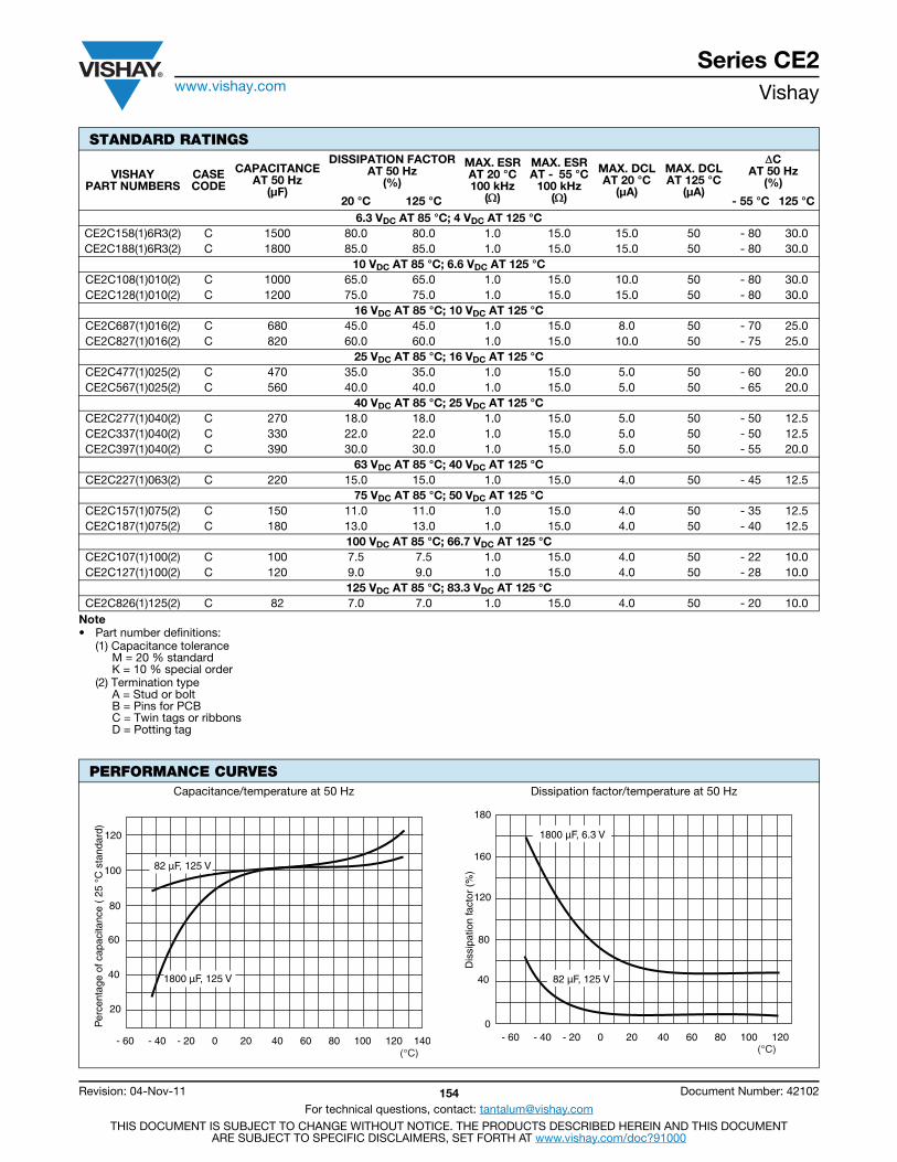
Series CE2www.vishay.com Vishay
Revision: 04-Nov-11 154 Document Number: 42102
For technical questions, contact: [email protected] DOCUMENT IS SUBJECT TO CHANGE WITHOUT NOTICE. THE PRODUCTS DESCRIBED HEREIN AND THIS DOCUMENT
ARE SUBJECT TO SPECIFIC DISCLAIMERS, SET FORTH AT www.vishay.com/doc?91000
Note• Part number definitions:
(1) Capacitance toleranceM = 20 % standardK = 10 % special order
(2) Termination typeA = Stud or boltB = Pins for PCBC = Twin tags or ribbonsD = Potting tag
STANDARD RATINGS
VISHAYPART NUMBERS
CASECODE
CAPACITANCEAT 50 Hz
(μF)
DISSIPATION FACTORAT 50 Hz
(%)
MAX. ESRAT 20 °C100 kHz
()
MAX. ESRAT - 55 °C
100 kHz()
MAX. DCLAT 20 °C
(μA)
MAX. DCLAT 125 °C
(μA)
CAT 50 Hz
(%)
20 °C 125 °C - 55 °C 125 °C6.3 VDC AT 85 °C; 4 VDC AT 125 °C
CE2C158(1)6R3(2) C 1500 80.0 80.0 1.0 15.0 15.0 50 - 80 30.0CE2C188(1)6R3(2) C 1800 85.0 85.0 1.0 15.0 15.0 50 - 80 30.0
10 VDC AT 85 °C; 6.6 VDC AT 125 °CCE2C108(1)010(2) C 1000 65.0 65.0 1.0 15.0 10.0 50 - 80 30.0CE2C128(1)010(2) C 1200 75.0 75.0 1.0 15.0 15.0 50 - 80 30.0
16 VDC AT 85 °C; 10 VDC AT 125 °CCE2C687(1)016(2) C 680 45.0 45.0 1.0 15.0 8.0 50 - 70 25.0CE2C827(1)016(2) C 820 60.0 60.0 1.0 15.0 10.0 50 - 75 25.0
25 VDC AT 85 °C; 16 VDC AT 125 °CCE2C477(1)025(2) C 470 35.0 35.0 1.0 15.0 5.0 50 - 60 20.0CE2C567(1)025(2) C 560 40.0 40.0 1.0 15.0 5.0 50 - 65 20.0
40 VDC AT 85 °C; 25 VDC AT 125 °CCE2C277(1)040(2) C 270 18.0 18.0 1.0 15.0 5.0 50 - 50 12.5CE2C337(1)040(2) C 330 22.0 22.0 1.0 15.0 5.0 50 - 50 12.5CE2C397(1)040(2) C 390 30.0 30.0 1.0 15.0 5.0 50 - 55 20.0
63 VDC AT 85 °C; 40 VDC AT 125 °CCE2C227(1)063(2) C 220 15.0 15.0 1.0 15.0 4.0 50 - 45 12.5
75 VDC AT 85 °C; 50 VDC AT 125 °CCE2C157(1)075(2) C 150 11.0 11.0 1.0 15.0 4.0 50 - 35 12.5CE2C187(1)075(2) C 180 13.0 13.0 1.0 15.0 4.0 50 - 40 12.5
100 VDC AT 85 °C; 66.7 VDC AT 125 °CCE2C107(1)100(2) C 100 7.5 7.5 1.0 15.0 4.0 50 - 22 10.0CE2C127(1)100(2) C 120 9.0 9.0 1.0 15.0 4.0 50 - 28 10.0
125 VDC AT 85 °C; 83.3 VDC AT 125 °CCE2C826(1)125(2) C 82 7.0 7.0 1.0 15.0 4.0 50 - 20 10.0
PERFORMANCE CURVESCapacitance/temperature at 50 Hz Dissipation factor/temperature at 50 Hz
120
100
80
60
40
20
Per
cent
age
of c
apac
itanc
e (
25 °
C s
tand
ard)
- 60 - 40 - 20 0 20 40 60 80 100 120 140 (°C)
82 µF, 125 V
1800 µF, 125 V
- 60 - 40 - 20 0 20 40 60 80 100 120 0
(°C)
Dis
sipa
tion
fact
or (
%)
120
180
160
80
40 82 µF, 125 V
1800 µF, 6.3 V
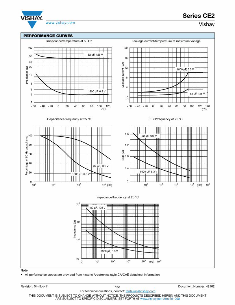
Series CE2www.vishay.com Vishay
Revision: 04-Nov-11 155 Document Number: 42102
For technical questions, contact: [email protected] DOCUMENT IS SUBJECT TO CHANGE WITHOUT NOTICE. THE PRODUCTS DESCRIBED HEREIN AND THIS DOCUMENT
ARE SUBJECT TO SPECIFIC DISCLAIMERS, SET FORTH AT www.vishay.com/doc?91000
Note• All performance curves are provided from historic Arcotronics style CA/CAE datasheet information
Impedance/temperature at 50 Hz Leakage current/temperature at maximum voltage
Capacitance/frequency at 25 °C ESR/frequency at 25 °C
Impedance/frequency at 25 °C
PERFORMANCE CURVES
Impe
danc
e (Ω
)
100
50
30
20
10
1
2
3
5
(°C)- 60 - 40 - 20 0 20 40 60 80 100 120
82 µF, 125 V
1800 µF, 6.3 V
- 60 - 40 - 20 0 20 40 60 80 100 120 140
20
16
12
8
4
0
(°C)
Leak
age
curr
ent (
µA
)
82 µF, 125 V
1800 µF, 6.3 V
100
80
60
40
20
0102 103 104101
1800 µF, 6.3 V
82 µF, 125 V
Per
cent
age
of 5
0 H
z ca
paci
tanc
e
(Hz) (Hz) 103 102 104 105 1060
0.4
0.8
1.2
1.6
ES
R (W
)
82 µF, 125 V
1800 µF, 6.3 V
Impe
danc
e (Ω
)
102
101
100
10-1
(Hz) 103 102 101 104 105 106
82 µF, 125 V
1800 µF, 6.3 V

Series CE2www.vishay.com Vishay
Revision: 04-Nov-11 156 Document Number: 42102
For technical questions, contact: [email protected] DOCUMENT IS SUBJECT TO CHANGE WITHOUT NOTICE. THE PRODUCTS DESCRIBED HEREIN AND THIS DOCUMENT
ARE SUBJECT TO SPECIFIC DISCLAIMERS, SET FORTH AT www.vishay.com/doc?91000
CROSS REFERENCEVISHAY PART NUMBER ARCOTRONICS PART NUMBER NATO PART NUMBER
CE
CE2C826M125A 402/1/50157/050
To be allocated
CE2C107M100A 402/1/50157/051
CE2C127M100A 402/1/50157/052
CE2C157M075A 402/1/50157/053
CE2C187M075A 402/1/50157/054
CE2C227M063A 402/1/50157/055
CE2C277M040A 402/1/50157/056
CE2C337M040A 402/1/50157/057
CE2C397M040A 402/1/50157/058
CE2C477M025A 402/1/50157/059
CE2C567M025A 402/1/50157/060
CE2C687M016A 402/1/50157/061
CE2C827M016A 402/1/50157/062
CE2C108M010A 402/1/50157/063
CE2C128M010A 402/1/50157/064
CE2C158M6R3A 402/1/50157/065
CE2C188M6R3A 402/1/50157/066
CEPC
CE2C826M125B 402/1/50158/050
To be allocated
CE2C107M100B 402/1/50158/051
CE2C127M100B 402/1/50158/052
CE2C157M075B 402/1/50158/053
CE2C187M075B 402/1/50158/054
CE2C227M063B 402/1/50158/055
CE2C277M040B 402/1/50158/056
CE2C337M040B 402/1/50158/057
CE2C397M040B 402/1/50158/058
CE2C477M025B 402/1/50158/059
CE2C567M025B 402/1/50158/060
CE2C687M016B 402/1/50158/061
CE2C827M016B 402/1/50158/062
CE2C108M010B 402/1/50158/063
CE2C128M010B 402/1/50158/064
CE2C158M6R3B 402/1/50158/065
CE2C188M6R3B 402/1/50158/066
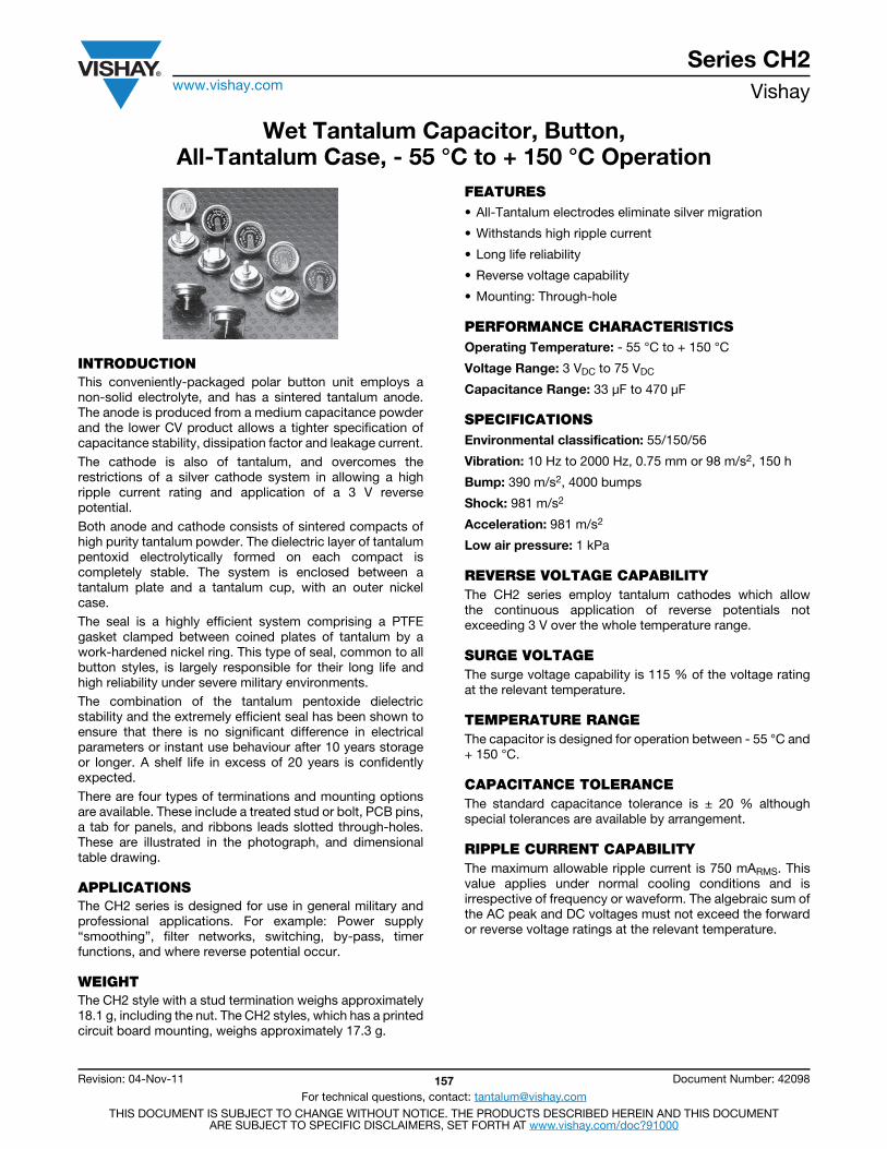
Series CH2www.vishay.com Vishay
Revision: 04-Nov-11 157 Document Number: 42098
For technical questions, contact: [email protected] DOCUMENT IS SUBJECT TO CHANGE WITHOUT NOTICE. THE PRODUCTS DESCRIBED HEREIN AND THIS DOCUMENT
ARE SUBJECT TO SPECIFIC DISCLAIMERS, SET FORTH AT www.vishay.com/doc?91000
Wet Tantalum Capacitor, Button,All-Tantalum Case, - 55 °C to + 150 °C Operation
INTRODUCTIONThis conveniently-packaged polar button unit employs anon-solid electrolyte, and has a sintered tantalum anode.The anode is produced from a medium capacitance powderand the lower CV product allows a tighter specification ofcapacitance stability, dissipation factor and leakage current.The cathode is also of tantalum, and overcomes therestrictions of a silver cathode system in allowing a highripple current rating and application of a 3 V reversepotential.Both anode and cathode consists of sintered compacts ofhigh purity tantalum powder. The dielectric layer of tantalumpentoxid electrolytically formed on each compact iscompletely stable. The system is enclosed between atantalum plate and a tantalum cup, with an outer nickelcase.The seal is a highly efficient system comprising a PTFEgasket clamped between coined plates of tantalum by awork-hardened nickel ring. This type of seal, common to allbutton styles, is largely responsible for their long life andhigh reliability under severe military environments.The combination of the tantalum pentoxide dielectricstability and the extremely efficient seal has been shown toensure that there is no significant difference in electricalparameters or instant use behaviour after 10 years storageor longer. A shelf life in excess of 20 years is confidentlyexpected.There are four types of terminations and mounting optionsare available. These include a treated stud or bolt, PCB pins,a tab for panels, and ribbons leads slotted through-holes.These are illustrated in the photograph, and dimensionaltable drawing.
APPLICATIONSThe CH2 series is designed for use in general military andprofessional applications. For example: Power supply“smoothing”, filter networks, switching, by-pass, timerfunctions, and where reverse potential occur.
WEIGHTThe CH2 style with a stud termination weighs approximately18.1 g, including the nut. The CH2 styles, which has a printedcircuit board mounting, weighs approximately 17.3 g.
FEATURES• All-Tantalum electrodes eliminate silver migration
• Withstands high ripple current
• Long life reliability
• Reverse voltage capability
• Mounting: Through-hole
PERFORMANCE CHARACTERISTICSOperating Temperature: - 55 °C to + 150 °C
Voltage Range: 3 VDC to 75 VDC
Capacitance Range: 33 μF to 470 μF
SPECIFICATIONSEnvironmental classification: 55/150/56
Vibration: 10 Hz to 2000 Hz, 0.75 mm or 98 m/s2, 150 h
Bump: 390 m/s2, 4000 bumps
Shock: 981 m/s2
Acceleration: 981 m/s2
Low air pressure: 1 kPa
REVERSE VOLTAGE CAPABILITYThe CH2 series employ tantalum cathodes which allowthe continuous application of reverse potentials notexceeding 3 V over the whole temperature range.
SURGE VOLTAGEThe surge voltage capability is 115 % of the voltage ratingat the relevant temperature.
TEMPERATURE RANGEThe capacitor is designed for operation between - 55 °C and+ 150 °C.
CAPACITANCE TOLERANCEThe standard capacitance tolerance is ± 20 % althoughspecial tolerances are available by arrangement.
RIPPLE CURRENT CAPABILITYThe maximum allowable ripple current is 750 mARMS. Thisvalue applies under normal cooling conditions and isirrespective of frequency or waveform. The algebraic sum ofthe AC peak and DC voltages must not exceed the forwardor reverse voltage ratings at the relevant temperature.
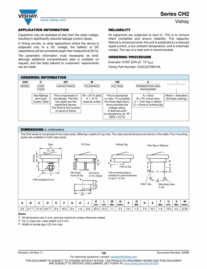
Series CH2www.vishay.com Vishay
Revision: 04-Nov-11 158 Document Number: 42098
For technical questions, contact: [email protected] DOCUMENT IS SUBJECT TO CHANGE WITHOUT NOTICE. THE PRODUCTS DESCRIBED HEREIN AND THIS DOCUMENT
ARE SUBJECT TO SPECIFIC DISCLAIMERS, SET FORTH AT www.vishay.com/doc?91000
APPLICATION INFORMATIONCapacitors may be operated at less than the rated voltage,resulting in significantly reduced leakage current values.
In timing circuits, or other applications where the device issubjected only to a DC voltage, the ballistic or DCcapacitance will be somewhat larger than measured at 50 Hz.
The parametric information must necessarily be brief,although additional comprehensive data is available onrequest, and the tests tailored to customers’ requirementscan be made.
RELIABILITYAll capacitors are subjected to burn-in. This is to removeinfant mortalities and ensure reliability. The capacitorlifetime is enhanced when the unit is subjected to a reducedripple current, a low ambient temperature, and is externallycooled. The use of a heat sink is recommended.
ORDERING PROCEDUREExample: CH2C (220 μF, 15 VDC)
Vishay Part Number: CH2C227M015A
Notes(1) All dimensions are in mm, and are maximum unless otherwise stated(2) For C case size, case height is 8.5 mm(3) Width of anode tag 4.22 mm max.
ORDERING INFORMATIONCH2 C 227 M 100 A -
MODEL CASECODE
CAPACITANCE TOLERANCE VOLTAGE TERMINATION ANDPACKAGING
See Ratingsand Case
Codes Table
This is expressed inpicofarads. The first
two digits are thesignificant figures.
The third is the numberof zeros to follow
M = 20 % (std)K = 10 %
(special order)
This is expressedin volts. To completethe three-digit block,
zeros precede thevoltage rating.
A decimal pointis indicated by an “R”
(6R3 = 6.3 V)
A = StudB = PC mount pins
C = Twin tag or ribbonD = Panel or potting tag
Blank = Standard(tin/lead coating)
DIMENSIONS in millimetersThe CH2 series is comprised of two case sizes, differing in depth of cup only. The case size dimensions are shown in the table. Four mounting styles are available in both case sizes.
A B C D E F G H J Kcrs.
Lcrs.
Mdia.
Nnom. P Q
dia. R S Tdia.
Ucrs.
Vdia.
Wnom.
3.6 6.7 (1) 21.8 8.4 (2) 8.4 16.2 8.4 1.8 0.8 20.3 10.2 1.1 2.4 13.1 1.0 7.5 10.7 1.6 13.0 3.5 0.30
E
F
4 BA shakeproof nut
AB
D
-
+
G
H20 S.W.G.H.T.D. Nickel
Mounting holes M dia.
J
L crs.
Kcrs.
-
+ +
-N
Hole Q dia.
This mounting style is suitable for panel thickness of up to 1.2 mm
+
-SR
WP
Ucrs.
Hole T dia. Mounting holes V dia.
Stud PC Pins Potting Tag Twin Tag or RibbonsC
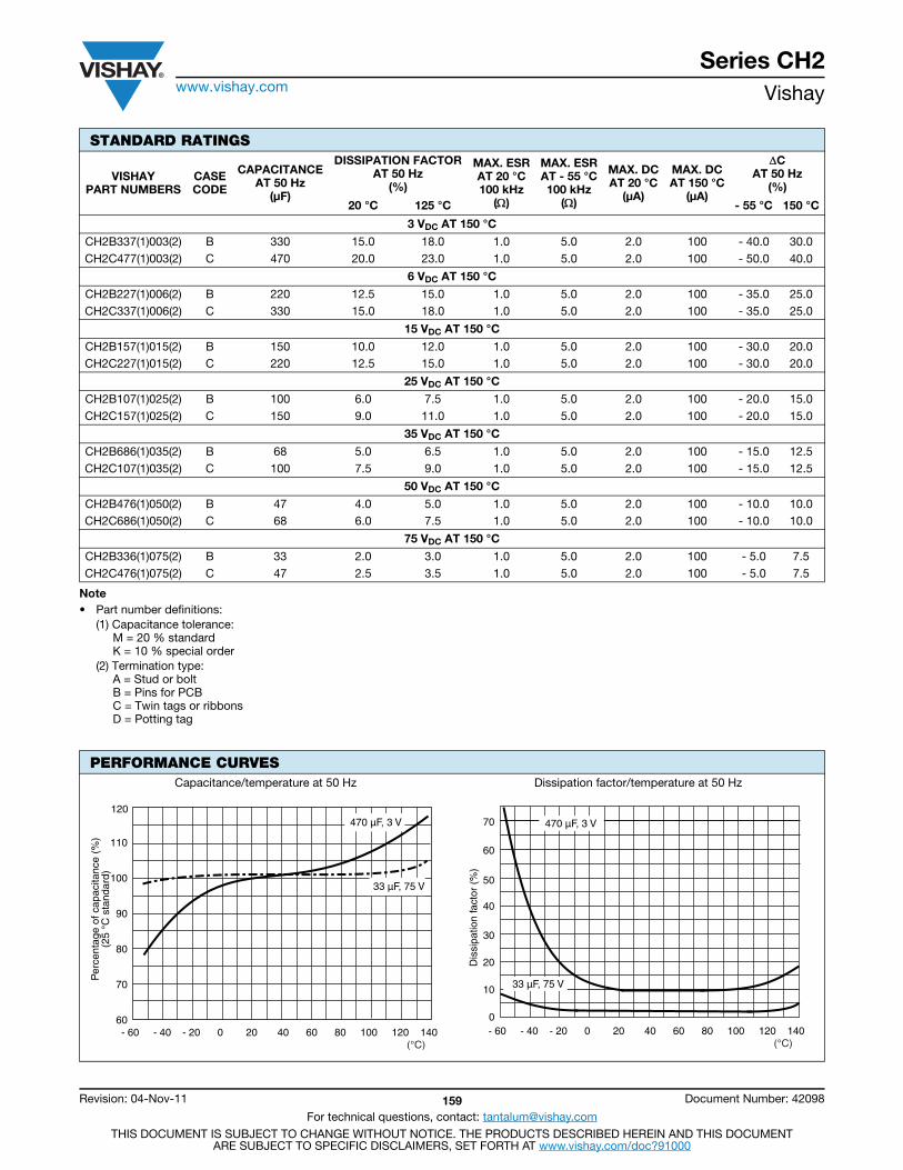
Series CH2www.vishay.com Vishay
Revision: 04-Nov-11 159 Document Number: 42098
For technical questions, contact: [email protected] DOCUMENT IS SUBJECT TO CHANGE WITHOUT NOTICE. THE PRODUCTS DESCRIBED HEREIN AND THIS DOCUMENT
ARE SUBJECT TO SPECIFIC DISCLAIMERS, SET FORTH AT www.vishay.com/doc?91000
Note• Part number definitions:
(1) Capacitance tolerance:M = 20 % standardK = 10 % special order
(2) Termination type:A = Stud or boltB = Pins for PCBC = Twin tags or ribbonsD = Potting tag
STANDARD RATINGS
VISHAYPART NUMBERS
CASECODE
CAPACITANCEAT 50 Hz
(μF)
DISSIPATION FACTORAT 50 Hz
(%)
MAX. ESRAT 20 °C100 kHz
()
MAX. ESRAT - 55 °C100 kHz
()
MAX. DCAT 20 °C
(μA)
MAX. DCAT 150 °C
(μA)
CAT 50 Hz
(%)
20 °C 125 °C - 55 °C 150 °C
3 VDC AT 150 °C
CH2B337(1)003(2) B 330 15.0 18.0 1.0 5.0 2.0 100 - 40.0 30.0CH2C477(1)003(2) C 470 20.0 23.0 1.0 5.0 2.0 100 - 50.0 40.0
6 VDC AT 150 °C
CH2B227(1)006(2) B 220 12.5 15.0 1.0 5.0 2.0 100 - 35.0 25.0CH2C337(1)006(2) C 330 15.0 18.0 1.0 5.0 2.0 100 - 35.0 25.0
15 VDC AT 150 °C
CH2B157(1)015(2) B 150 10.0 12.0 1.0 5.0 2.0 100 - 30.0 20.0CH2C227(1)015(2) C 220 12.5 15.0 1.0 5.0 2.0 100 - 30.0 20.0
25 VDC AT 150 °C
CH2B107(1)025(2) B 100 6.0 7.5 1.0 5.0 2.0 100 - 20.0 15.0CH2C157(1)025(2) C 150 9.0 11.0 1.0 5.0 2.0 100 - 20.0 15.0
35 VDC AT 150 °C
CH2B686(1)035(2) B 68 5.0 6.5 1.0 5.0 2.0 100 - 15.0 12.5CH2C107(1)035(2) C 100 7.5 9.0 1.0 5.0 2.0 100 - 15.0 12.5
50 VDC AT 150 °C
CH2B476(1)050(2) B 47 4.0 5.0 1.0 5.0 2.0 100 - 10.0 10.0CH2C686(1)050(2) C 68 6.0 7.5 1.0 5.0 2.0 100 - 10.0 10.0
75 VDC AT 150 °C
CH2B336(1)075(2) B 33 2.0 3.0 1.0 5.0 2.0 100 - 5.0 7.5CH2C476(1)075(2) C 47 2.5 3.5 1.0 5.0 2.0 100 - 5.0 7.5
PERFORMANCE CURVESCapacitance/temperature at 50 Hz Dissipation factor/temperature at 50 Hz
110
100
90
80
70
60
120
- 60 - 40 - 20 0 20 40 60 80 100 120 140 (°C)
Per
cent
age
of c
apac
itanc
e (%
)(2
5 °C
sta
ndar
d)
470 µF, 3 V
33 µF, 75 V
Dis
sipa
tion
fact
or (
%)
0
10
20
30
40
50
60
70
- 60 - 40 - 20 0 20 40 60 80 100 120 140 (°C)
470 µF, 3 V
33 µF, 75 V
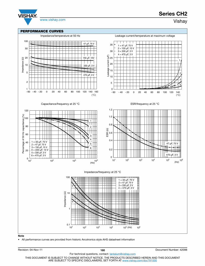
Series CH2www.vishay.com Vishay
Revision: 04-Nov-11 160 Document Number: 42098
For technical questions, contact: [email protected] DOCUMENT IS SUBJECT TO CHANGE WITHOUT NOTICE. THE PRODUCTS DESCRIBED HEREIN AND THIS DOCUMENT
ARE SUBJECT TO SPECIFIC DISCLAIMERS, SET FORTH AT www.vishay.com/doc?91000
Note• All performance curves are provided from historic Arcotronics style AHS datasheet information
Impedance/temperature at 50 Hz Leakage current/temperature at maximum voltage
Capacitance/frequency at 25 °C ESR/frequency at 25 °C
Impedance/frequency at 25 °C
PERFORMANCE CURVES
(°C)
100
50
20
10
2
1
5Impe
danc
e (Ω
)
- 60 - 40 - 20 0 20 40 60 80 100 120 140 160
47 µF, 75 V
150 µF, 15V
330 µF, 3 V
470 µF, 3 V Leak
age
curr
ent (
µF
)
0
5
10
15
20
25
30
35
- 60 - 40 - 20 0 20 40 60 80 100 120 140 (°C)
1 = 47 µF, 75 V 2 = 150 µF, 15 V 3 = 330 µF, 3 V 4 = 470 µF, 3 V
1
2
3
4
Per
cent
age
of 5
0 H
z ca
paci
tanc
e (%
)
100
80
60
40
20
0
120
102 103 104101
(Hz)
2 = 47 µF, 75 V3 = 150 µF, 15 V
5 = 330 µF, 3 V6 = 470 µF, 3 V
4 = 220 µF, 15 V
1 = 33 µF, 75 V
1
2
3
4
5
6
(Hz) 103 102 101 104 105 106
0
0.4
0.6
0.2
0.8
1.0
1.2E
SR
(Ω
)
47 µF, 75 V
470 µF, 3 V
Impe
danc
e (Ω
)
100
10
1
0.1 (Hz) 102 101 103 104 105 106
1
2
3
4
2 = 47 µF, 75 V3 = 330 µF, 3 V4 = 470 µF, 3 V
1 = 33 µF, 75 V
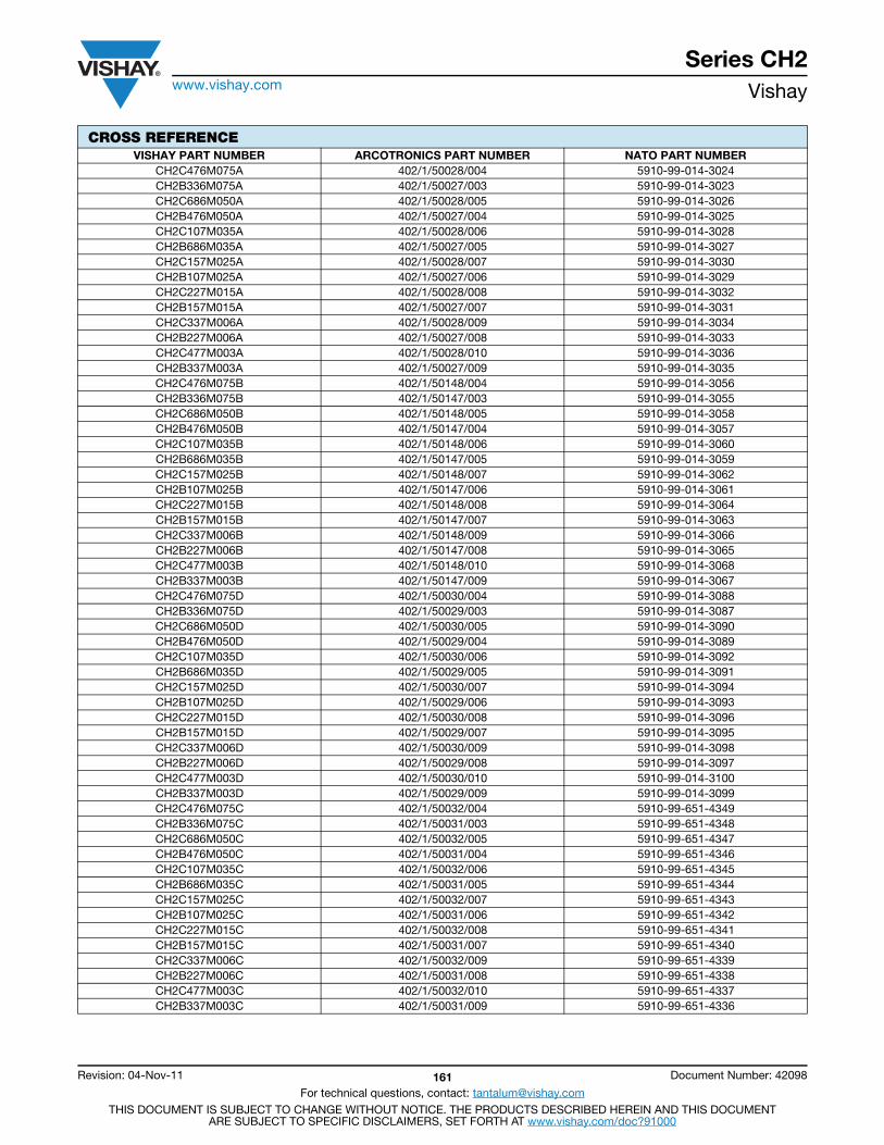
Series CH2www.vishay.com Vishay
Revision: 04-Nov-11 161 Document Number: 42098
For technical questions, contact: [email protected] DOCUMENT IS SUBJECT TO CHANGE WITHOUT NOTICE. THE PRODUCTS DESCRIBED HEREIN AND THIS DOCUMENT
ARE SUBJECT TO SPECIFIC DISCLAIMERS, SET FORTH AT www.vishay.com/doc?91000
CROSS REFERENCEVISHAY PART NUMBER ARCOTRONICS PART NUMBER NATO PART NUMBER
CH2C476M075A 402/1/50028/004 5910-99-014-3024CH2B336M075A 402/1/50027/003 5910-99-014-3023CH2C686M050A 402/1/50028/005 5910-99-014-3026CH2B476M050A 402/1/50027/004 5910-99-014-3025CH2C107M035A 402/1/50028/006 5910-99-014-3028CH2B686M035A 402/1/50027/005 5910-99-014-3027CH2C157M025A 402/1/50028/007 5910-99-014-3030CH2B107M025A 402/1/50027/006 5910-99-014-3029CH2C227M015A 402/1/50028/008 5910-99-014-3032CH2B157M015A 402/1/50027/007 5910-99-014-3031CH2C337M006A 402/1/50028/009 5910-99-014-3034CH2B227M006A 402/1/50027/008 5910-99-014-3033CH2C477M003A 402/1/50028/010 5910-99-014-3036CH2B337M003A 402/1/50027/009 5910-99-014-3035CH2C476M075B 402/1/50148/004 5910-99-014-3056CH2B336M075B 402/1/50147/003 5910-99-014-3055CH2C686M050B 402/1/50148/005 5910-99-014-3058CH2B476M050B 402/1/50147/004 5910-99-014-3057CH2C107M035B 402/1/50148/006 5910-99-014-3060CH2B686M035B 402/1/50147/005 5910-99-014-3059CH2C157M025B 402/1/50148/007 5910-99-014-3062CH2B107M025B 402/1/50147/006 5910-99-014-3061CH2C227M015B 402/1/50148/008 5910-99-014-3064CH2B157M015B 402/1/50147/007 5910-99-014-3063CH2C337M006B 402/1/50148/009 5910-99-014-3066CH2B227M006B 402/1/50147/008 5910-99-014-3065CH2C477M003B 402/1/50148/010 5910-99-014-3068CH2B337M003B 402/1/50147/009 5910-99-014-3067CH2C476M075D 402/1/50030/004 5910-99-014-3088CH2B336M075D 402/1/50029/003 5910-99-014-3087CH2C686M050D 402/1/50030/005 5910-99-014-3090CH2B476M050D 402/1/50029/004 5910-99-014-3089CH2C107M035D 402/1/50030/006 5910-99-014-3092CH2B686M035D 402/1/50029/005 5910-99-014-3091CH2C157M025D 402/1/50030/007 5910-99-014-3094CH2B107M025D 402/1/50029/006 5910-99-014-3093CH2C227M015D 402/1/50030/008 5910-99-014-3096CH2B157M015D 402/1/50029/007 5910-99-014-3095CH2C337M006D 402/1/50030/009 5910-99-014-3098CH2B227M006D 402/1/50029/008 5910-99-014-3097CH2C477M003D 402/1/50030/010 5910-99-014-3100CH2B337M003D 402/1/50029/009 5910-99-014-3099CH2C476M075C 402/1/50032/004 5910-99-651-4349CH2B336M075C 402/1/50031/003 5910-99-651-4348CH2C686M050C 402/1/50032/005 5910-99-651-4347CH2B476M050C 402/1/50031/004 5910-99-651-4346CH2C107M035C 402/1/50032/006 5910-99-651-4345CH2B686M035C 402/1/50031/005 5910-99-651-4344CH2C157M025C 402/1/50032/007 5910-99-651-4343CH2B107M025C 402/1/50031/006 5910-99-651-4342CH2C227M015C 402/1/50032/008 5910-99-651-4341CH2B157M015C 402/1/50031/007 5910-99-651-4340CH2C337M006C 402/1/50032/009 5910-99-651-4339CH2B227M006C 402/1/50031/008 5910-99-651-4338CH2C477M003C 402/1/50032/010 5910-99-651-4337CH2B337M003C 402/1/50031/009 5910-99-651-4336
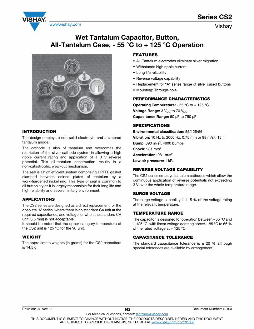
Series CS2www.vishay.com Vishay
Revision: 04-Nov-11 162 Document Number: 42103
For technical questions, contact: [email protected] DOCUMENT IS SUBJECT TO CHANGE WITHOUT NOTICE. THE PRODUCTS DESCRIBED HEREIN AND THIS DOCUMENT
ARE SUBJECT TO SPECIFIC DISCLAIMERS, SET FORTH AT www.vishay.com/doc?91000
Wet Tantalum Capacitor, Button,All-Tantalum Case, - 55 °C to + 125 °C Operation
INTRODUCTIONThe design employs a non-solid electrolyte and a sinteredtantalum anode.
The cathode is also of tantalum and overcomes therestriction of the silver cathode system in allowing a highripple current rating and application of a 3 V reversepotential. This all-tantalum construction results in anon-catastrophic wear-out mechanism.
The seal is a high efficient system comprising a PTFE gasketclamped between coined plates of tantalum by awork-hardened nickel ring. This type of seal is common toall button styles it is largely responsible for their long life andhigh reliability and severe military environment.
APPLICATIONSThe CS2 series are designed as a direct replacement for theobsolete ‘A’ series, where there is no standard CA unit at therequired capacitance, and voltage, or when the standard CAunit (8.5 mm) is not acceptable.It should be noted that the upper category temperature ofthe CS2 unit is 125 °C for the ‘A’ unit.
WEIGHTThe approximate weights (in grams) for the CS2 capacitorsis 14.5 g.
FEATURES• All-Tantalum electrodes eliminate silver migration
• Withstands high ripple current
• Long life reliability
• Reverse voltage capability
• Replacement for “A” series range of silver cased buttons
• Mounting: Through-hole
PERFORMANCE CHARACTERISTICSOperating Temperature: - 55 °C to + 125 °C
Voltage Range: 3 VDC to 70 VDC
Capacitance Range: 50 μF to 750 μF
SPECIFICATIONSEnvironmental classification: 55/125/56
Vibration: 10 Hz to 2000 Hz, 0.75 mm or 98 m/s2, 15 h
Bump: 390 m/s2, 4000 bumps
Shock: 981 m/s2
Acceleration: 981 m/s2
Low air pressure: 1 kPa
REVERSE VOLTAGE CAPABILITYThe CS2 series employs tantalum cathodes which allow thecontinuous application of reverse potentials not exceeding3 V over the whole temperature range.
SURGE VOLTAGEThe surge voltage capability is 115 % of the voltage ratingat the relevant temperature.
TEMPERATURE RANGEThe capacitor is designed for operation between - 55 °C and+ 125 °C, with linear voltage derating above + 85 °C to 66 %of the rated voltage at + 125 °C.
CAPACITANCE TOLERANCEThe standard capacitance tolerance is ± 20 % althoughspecial tolerances are available by arrangement.
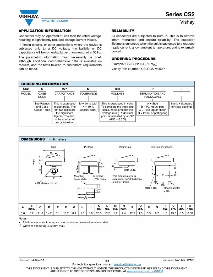
Series CS2www.vishay.com Vishay
Revision: 04-Nov-11 163 Document Number: 42103
For technical questions, contact: [email protected] DOCUMENT IS SUBJECT TO CHANGE WITHOUT NOTICE. THE PRODUCTS DESCRIBED HEREIN AND THIS DOCUMENT
ARE SUBJECT TO SPECIFIC DISCLAIMERS, SET FORTH AT www.vishay.com/doc?91000
APPLICATION INFORMATIONCapacitors may be operated at less than the rated voltage,resulting in significantly reduced leakage current values.
In timing circuits, or other applications where the device issubjected only to a DC voltage, the ballistic or DCcapacitance will be somewhat larger than measured at 50 Hz.
The parametric information must necessarily be brief,although additional comprehensive data is available onrequest, and the tests tailored to customers’ requirementscan be made.
RELIABILITYAll capacitors are subjected to burn-in. This is to removeinfant mortalities and ensure reliability. The capacitorlifetime is enhanced when the unit is subjected to a reducedripple current, a low ambient temperature, and is externallycooled.
ORDERING PROCEDUREExample: CS2C (220 μF, 50 VDC)
Vishay Part Number: CS2C227M050P
Notes• All dimensions are in mm, and are maximum unless otherwise stated(1) Width of anode tag 4.22 mm max.
ORDERING INFORMATIONCS2 C 227 M 050 P -
MODEL CASECODE
CAPACITANCE TOLERANCE VOLTAGE TERMINATION ANDPACKAGING
See Ratingsand Case
Codes Table
This is expressedin picofarads. Thefirst two digits are
the significantfigures. The thirdis the number ofzeros to follow
M = 20 % (std)K = 10 %
(special order)
This is expressed in volts.To complete the three-digitblock, zeros precede thevoltage rating. A decimal
point is indicated by an “R”(6R3 = 6.3 V)
A = StudB = PC mount pins
C = Twin tag or ribbonD = Panel or potting tag
Blank = Standard(tin/lead coating)
DIMENSIONS in millimeters
A B max. C D E F G H J K
crs.L
crs.M
dia.N
nom. P Qdia. R S T
dia.U
crs.V
dia.W
nom.
3.6 6.7 21.8 8.4 (1) 8.1 16.2 8.4 1.8 0.8 20.3 10.2 1.1 2.4 12.9 1.0 6.5 9.7 1.6 13.0 3.5 0.30
E
F
4 BA shakeproof nut
AB
D
-
+
G
H20 S.W.G.H.T.D. Nickel
Mounting holes M dia.
J
L crs.
Kcrs.
-
+ +
-NHole Q dia.
This mounting style is suitable for panel thickness of up to 1.2 mm
+
-SR
WP
Ucrs.
Hole T dia. Mounting holes V dia.
Stud PC Pins Potting Tag Twin Tag or Ribbons

Series CS2www.vishay.com Vishay
Revision: 04-Nov-11 164 Document Number: 42103
For technical questions, contact: [email protected] DOCUMENT IS SUBJECT TO CHANGE WITHOUT NOTICE. THE PRODUCTS DESCRIBED HEREIN AND THIS DOCUMENT
ARE SUBJECT TO SPECIFIC DISCLAIMERS, SET FORTH AT www.vishay.com/doc?91000
Notes• Part number definitions:
(1) Capacitance toleranceM = 20 % standardK = 10 % special order
(2) Termination typeA = Stud or boltB = Pins for PCBC = Twin tags or ribbonsD = Potting tag
Note(1) Special tolerance of + 20 % to 0 %
STANDARD RATINGS
VISHAYPART NUMBERS
CASECODE
CAP. AT 50 Hz(μF)
DISSIPATION FACTOR AT
50 Hz(%)
MAX. ESRAT 25 °C100 kHz
()
MAX. ESRAT - 55 °C100 kHz
()
MAX. DCLAT 25 °C
(μA)
MAX. DCLAT 125 °C
(μA)
CAT 50 Hz
(%)
20 °C 125 °C - 55 °C 125 °C
70 VDC AT 85 °C; 54 VDC AT 125 °CCS2B506(1)070(2) B 50 5.0 - 1.0 5.0 3.0 50 10 -
30 VDC AT 85 °C; 23 VDC AT 125 °CCS2B147(1)030(2) B 140 15 - 1.0 5.0 3.0 50 30 -
15 VDC AT 85 °C; 11.3 VDC AT 125 °CCS2B257(1)015(2) B 250 25 - 1.0 5.0 3.0 50 50 -
6 VDC AT 85 °C; 4.6 VDC AT 125 °CCS2B507(1)006(2) B 500 40 - 1.0 5.0 3.0 50 60 -
3 VDC AT 85 °C; 2.3 VDC AT 125 °CCS2B757(1)003(2) B 750 50 - 1.0 5.0 3.0 50 75 -
CROSS REFERENCEVISHAY PART NUMBER ARCOTRONICS PART NUMBER
CS2 (STUD)CS2B506M070A 402/1/50159/001CS2B147M030A 402/1/50159/002CS2B257M015A 402/1/50159/004CS2B507M006A 402/1/50159/007CS2B757M003A 402/1/50159/005
Contact marketing (1) 402/1/50159/012CS2 (PC PINS)
CS2B506M070B 402/1/50175/001CS2B147M030B 402/1/50175/002CS2B257M015B 402/1/50175/004CS2B507M006B 402/1/50175/007CS2B757M003B 402/1/50175/005
Contact marketing (1) 402/1/50175/012CS2 (TWIN TAGS)
CS2B506M070C 402/1/50183/001CS2B147M030C 402/1/50183/002CS2B257M015C 402/1/50183/004CS2B507M006C 402/1/50183/007CS2B757M003C 402/1/50183/005
Contact marketing (1) 402/1/50183/012CS2 (PANEL TAG)
CS2B506M070D 402/1/50169/001CS2B147M030D 402/1/50169/002CS2B257M015D 402/1/50169/004CS2B507M006D 402/1/50169/007CS2B757M003D 402/1/50169/005
Contact marketing (1) 402/1/50169/012

Contents
M34.................................166
M35.................................170
Custom Design ..............203
Guide to Application........25Surface
Mount Wet Tantalum Capacitor
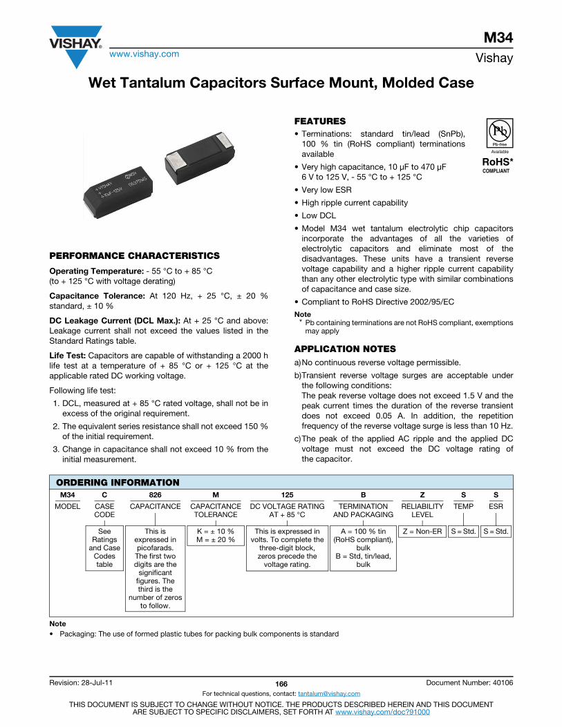
M34www.vishay.com Vishay
Revision: 28-Jul-11 166 Document Number: 40106
For technical questions, contact: [email protected]
THIS DOCUMENT IS SUBJECT TO CHANGE WITHOUT NOTICE. THE PRODUCTS DESCRIBED HEREIN AND THIS DOCUMENTARE SUBJECT TO SPECIFIC DISCLAIMERS, SET FORTH AT www.vishay.com/doc?91000
Wet Tantalum Capacitors Surface Mount, Molded Case
PERFORMANCE CHARACTERISTICS
Operating Temperature: - 55 °C to + 85 °C(to + 125 °C with voltage derating)
Capacitance Tolerance: At 120 Hz, + 25 °C, ± 20 %standard, ± 10 %
DC Leakage Current (DCL Max.): At + 25 °C and above:Leakage current shall not exceed the values listed in theStandard Ratings table.
Life Test: Capacitors are capable of withstanding a 2000 hlife test at a temperature of + 85 °C or + 125 °C at theapplicable rated DC working voltage.
Following life test:
1. DCL, measured at + 85 °C rated voltage, shall not be inexcess of the original requirement.
2. The equivalent series resistance shall not exceed 150 %of the initial requirement.
3. Change in capacitance shall not exceed 10 % from theinitial measurement.
FEATURES• Terminations: standard tin/lead (SnPb),
100 % tin (RoHS compliant) terminationsavailable
• Very high capacitance, 10 μF to 470 μF 6 V to 125 V, - 55 °C to + 125 °C
• Very low ESR
• High ripple current capability
• Low DCL
• Model M34 wet tantalum electrolytic chip capacitorsincorporate the advantages of all the varieties ofelectrolytic capacitors and eliminate most of thedisadvantages. These units have a transient reversevoltage capability and a higher ripple current capabilitythan any other electrolytic type with similar combinationsof capacitance and case size.
• Compliant to RoHS Directive 2002/95/EC
Note* Pb containing terminations are not RoHS compliant, exemptions
may apply
APPLICATION NOTESa)No continuous reverse voltage permissible.
b)Transient reverse voltage surges are acceptable underthe following conditions:The peak reverse voltage does not exceed 1.5 V and thepeak current times the duration of the reverse transientdoes not exceed 0.05 A. In addition, the repetitionfrequency of the reverse voltage surge is less than 10 Hz.
c)The peak of the applied AC ripple and the applied DCvoltage must not exceed the DC voltage rating ofthe capacitor.
Note• Packaging: The use of formed plastic tubes for packing bulk components is standard
ORDERING INFORMATIONM34 C 826 M 125 B Z S S
MODEL CASECODE
CAPACITANCE CAPACITANCETOLERANCE
DC VOLTAGE RATINGAT + 85 °C
TERMINATIONAND PACKAGING
RELIABILITYLEVEL
TEMP ESR
SeeRatings
and CaseCodestable
This isexpressed inpicofarads.The first two digits are the
significantfigures. Thethird is the
number of zerosto follow.
K = ± 10 %M = ± 20 %
This is expressed involts. To complete the
three-digit block,zeros precede the
voltage rating.
A = 100 % tin(RoHS compliant),
bulkB = Std, tin/lead,
bulk
Z = Non-ER S = Std. S = Std.
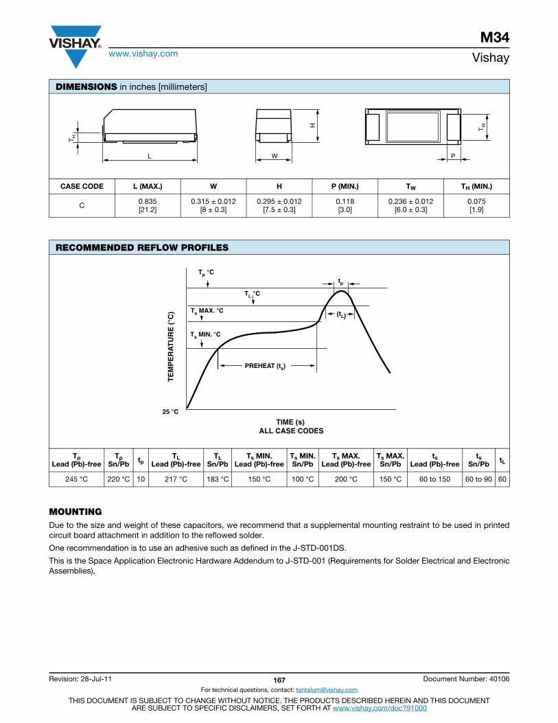
M34www.vishay.com Vishay
Revision: 28-Jul-11 167 Document Number: 40106
For technical questions, contact: [email protected]
THIS DOCUMENT IS SUBJECT TO CHANGE WITHOUT NOTICE. THE PRODUCTS DESCRIBED HEREIN AND THIS DOCUMENTARE SUBJECT TO SPECIFIC DISCLAIMERS, SET FORTH AT www.vishay.com/doc?91000
MOUNTINGDue to the size and weight of these capacitors, we recommend that a supplemental mounting restraint to be used in printedcircuit board attachment in addition to the reflowed solder.
One recommendation is to use an adhesive such as defined in the J-STD-001DS.
This is the Space Application Electronic Hardware Addendum to J-STD-001 (Requirements for Solder Electrical and ElectronicAssemblies).
DIMENSIONS in inches [millimeters]
CASE CODE L (MAX.) W H P (MIN.) TW TH (MIN.)
C 0.835[21.2]
0.315 ± 0.012[8 ± 0.3]
0.295 ± 0.012[7.5 ± 0.3]
0.118[3.0]
0.236 ± 0.012[6.0 ± 0.3]
0.075[1.9]
RECOMMENDED REFLOW PROFILES
Tp Lead (Pb)-free
Tp Sn/Pb tp
TLLead (Pb)-free
TLSn/Pb
Ts MIN.Lead (Pb)-free
Ts MIN.Sn/Pb
Ts MAX.Lead (Pb)-free
Ts MAX.Sn/Pb
tsLead (Pb)-free
tsSn/Pb tL
245 °C 220 °C 10 217 °C 183 °C 150 °C 100 °C 200 °C 150 °C 60 to 150 60 to 90 60
TH
H TW
L W P
TE
MP
ER
AT
UR
E (
°C)
25 °C
TIME (s) ALL CASE CODES
Tp °C
TL °C
Ts MAX. °C
Ts MIN. °C
tp
(tL)
PREHEAT (ts)
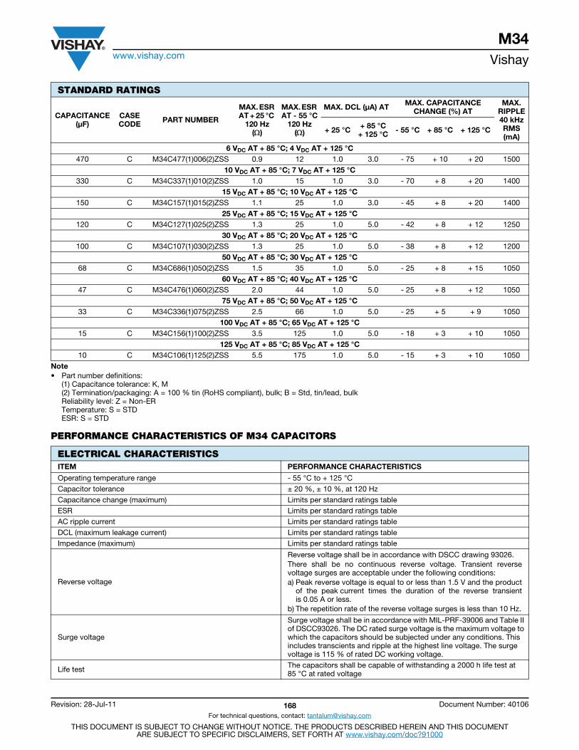
M34www.vishay.com Vishay
Revision: 28-Jul-11 168 Document Number: 40106
For technical questions, contact: [email protected]
THIS DOCUMENT IS SUBJECT TO CHANGE WITHOUT NOTICE. THE PRODUCTS DESCRIBED HEREIN AND THIS DOCUMENTARE SUBJECT TO SPECIFIC DISCLAIMERS, SET FORTH AT www.vishay.com/doc?91000
Note• Part number definitions:
(1) Capacitance tolerance: K, M(2) Termination/packaging: A = 100 % tin (RoHS compliant), bulk; B = Std, tin/lead, bulkReliability level: Z = Non-ERTemperature: S = STDESR: S = STD
PERFORMANCE CHARACTERISTICS OF M34 CAPACITORS
STANDARD RATINGS
CAPACITANCE(μF)
CASE CODE PART NUMBER
MAX. ESR AT + 25 °C
120 Hz()
MAX. ESR AT - 55 °C
120 Hz()
MAX. DCL (μA) AT MAX. CAPACITANCECHANGE (%) AT
MAX.RIPPLE40 kHzRMS(mA)
+ 25 °C + 85 °C+ 125 °C - 55 °C + 85 °C + 125 °C
6 VDC AT + 85 °C; 4 VDC AT + 125 °C470 C M34C477(1)006(2)ZSS 0.9 12 1.0 3.0 - 75 + 10 + 20 1500
10 VDC AT + 85 °C; 7 VDC AT + 125 °C330 C M34C337(1)010(2)ZSS 1.0 15 1.0 3.0 - 70 + 8 + 20 1400
15 VDC AT + 85 °C; 10 VDC AT + 125 °C150 C M34C157(1)015(2)ZSS 1.1 25 1.0 3.0 - 45 + 8 + 20 1400
25 VDC AT + 85 °C; 15 VDC AT + 125 °C 120 C M34C127(1)025(2)ZSS 1.3 25 1.0 5.0 - 42 + 8 + 12 1250
30 VDC AT + 85 °C; 20 VDC AT + 125 °C100 C M34C107(1)030(2)ZSS 1.3 25 1.0 5.0 - 38 + 8 + 12 1200
50 VDC AT + 85 °C; 30 VDC AT + 125 °C68 C M34C686(1)050(2)ZSS 1.5 35 1.0 5.0 - 25 + 8 + 15 1050
60 VDC AT + 85 °C; 40 VDC AT + 125 °C47 C M34C476(1)060(2)ZSS 2.0 44 1.0 5.0 - 25 + 8 + 12 1050
75 VDC AT + 85 °C; 50 VDC AT + 125 °C33 C M34C336(1)075(2)ZSS 2.5 66 1.0 5.0 - 25 + 5 + 9 1050
100 VDC AT + 85 °C; 65 VDC AT + 125 °C 15 C M34C156(1)100(2)ZSS 3.5 125 1.0 5.0 - 18 + 3 + 10 1050
125 VDC AT + 85 °C; 85 VDC AT + 125 °C 10 C M34C106(1)125(2)ZSS 5.5 175 1.0 5.0 - 15 + 3 + 10 1050
ELECTRICAL CHARACTERISTICSITEM PERFORMANCE CHARACTERISTICS
Operating temperature range - 55 °C to + 125 °C Capacitor tolerance ± 20 %, ± 10 %, at 120 HzCapacitance change (maximum) Limits per standard ratings tableESR Limits per standard ratings tableAC ripple current Limits per standard ratings tableDCL (maximum leakage current) Limits per standard ratings tableImpedance (maximum) Limits per standard ratings table
Reverse voltage
Reverse voltage shall be in accordance with DSCC drawing 93026.There shall be no continuous reverse voltage. Transient reversevoltage surges are acceptable under the following conditions:a) Peak reverse voltage is equal to or less than 1.5 V and the product
of the peak current times the duration of the reverse transientis 0.05 A or less.
b) The repetition rate of the reverse voltage surges is less than 10 Hz.
Surge voltage
Surge voltage shall be in accordance with MIL-PRF-39006 and Table II of DSCC93026. The DC rated surge voltage is the maximum voltage to which the capacitors should be subjected under any conditions. This includes transcients and ripple at the highest line voltage. The surge voltage is 115 % of rated DC working voltage.
Life test The capacitors shall be capable of withstanding a 2000 h life test at 85 °C at rated voltage

M34www.vishay.com Vishay
Revision: 28-Jul-11 169 Document Number: 40106
For technical questions, contact: [email protected]
THIS DOCUMENT IS SUBJECT TO CHANGE WITHOUT NOTICE. THE PRODUCTS DESCRIBED HEREIN AND THIS DOCUMENTARE SUBJECT TO SPECIFIC DISCLAIMERS, SET FORTH AT www.vishay.com/doc?91000
ENVIRONMENTAL CHARACTERISTICSITEM CONDITION COMMENTS
Hermeticity MIL-PRF-39006 There shall be no evidence of leakage after testing to MIL-PRF-39006 specifications.
Moisture resistance MIL-PRF-39006 Tested in accordance to MIL-PRF-39006 for 30 cycles.
Altitude MIL-STD-202G, method 105 D 100 000 feet test
MECHANICAL CHARACTERISTICSITEM CONDITION COMMENTS
Thermal shock MIL-STD-202G, method 107 A Per M39006 and DSCC93026, 30 cycles
Shock MIL-STD-202G, method 213 I Per M39006 and DSCC93026, 100 g
Vibration (high frequency) MIL-STD-202G, method 204 D Per M39006 and DSCC93026, 20 g
Resistance to solder heat MIL-STD-202G, method 210 FTerminals at 260 °C for 10 s. The capacitor must not be visibly damaged and the electrical characteristics must not be affected.
Solderability ANSI J-STD-002 The terminations must be solderable per the MIL standard.
Terminals MIL-STD-1276All terminals shall be permanently secured internally and externally, as applicable. All external joints shall be welded.
Part markings MIL-STD-1285The part marking shall include Vishay name, trademark, capacitance, voltage, date code and lot symbol.
Weight (typical) in g 3.5
PAD DIMENSIONS in millimeters
CASE CODE A (MIN.) B (NOM.) C (NOM.) D (NOM.)
C 22.7 14.7 4.0 6.4
STANDARD PACKAGING QUANTITYSERIES CASE CODE BULK/TUBE
M34 C 10 pcs
A
C B
D
C

M35www.vishay.com Vishay
Revision: 07-Nov-11 170 Document Number: 40095
For technical questions, contact: [email protected] DOCUMENT IS SUBJECT TO CHANGE WITHOUT NOTICE. THE PRODUCTS DESCRIBED HEREIN AND THIS DOCUMENT
ARE SUBJECT TO SPECIFIC DISCLAIMERS, SET FORTH AT www.vishay.com/doc?91000
Wet Tantalum Capacitors Surface Mount, Molded Case
FEATURES• Molded surface mountable design• Terminations: standard tin/lead (SnPb),
100 % tin (RoHS compliant) available• Industry standard ratings• Model M35 wet tantalum electrolytic chip
capacitors incorporate the advantages of all thevarieties of electrolytic capacitors and eliminate most ofthe disadvantages. These units have a 3 V reverse voltagecapability at + 85 °C and a higher ripple current capabilitythan any other electrolytic type with similar combinationsof capacitance and case size.
• Compliant to RoHS Directive 2002/95/ECNote
* Pb containing terminations are not RoHS compliant, exemptionsmay apply
PERFORMANCE CHARACTERISTICSOperating Temperature: - 55 °C to + 85 °C (to + 125 °C with voltage derating)Capacitance Tolerance: At 120 Hz, + 25 °C. ± 20 %standard. ± 10 %, ± 5 % available as special.DC Leakage Current (DCL Max.): At + 25 °C and above:Leakage current shall not exceed the values listed in theStandard Ratings Tables.
Life Test: Capacitors are capable of withstanding a 2000 hlife test at a temperature of + 85 °C or + 125 °C at theapplicable rated DC working voltage. Following life test:1. DCL, measured at + 85 °C rated voltage, shall not be in
excess of the original requirement.2. The equivalent series resistance shall not exceed 150 %
of the initial requirement.3. Change in capacitance shall not exceed 10 % from the
initial measurement.
Note• Packaging: The use of formed plastic tubes for packing bulk components is standard
ORDERING INFORMATIONM35 C 826 M 125 B Z S L
MODEL CASECODE
CAPACITANCE CAPACITANCETOLERANCE
DC VOLTAGE RATINGAT + 85 °C
TERMINATIONAND PACKAGING
RELIABILITYLEVEL
TEMP ESR
SeeRatings
and CaseCodestable
This isexpressed inpicofarads.The first two digits are the
significantfigures. The third is the
number of zerosto follow.
K = ± 10 %M = ± 20 %
This is expressed involts. To complete the
three-digit block,zeros precede the
voltage rating.A decimal point is
indicated by an “R”(6R3 = 6.3 V)
A = 100 % tin(RoHS compliant),
bulkB = Std, tin/lead,
bulk
Z = Non-ER S = Std S = Std.L = Low
DIMENSIONS in inches [millimeters]
CASE CODE L (MAX.) W H P (MIN.) TW TH (MIN.)
C 0.835[21.2]
0.315 ± 0.012[8 ± 0.3]
0.295 ± 0.012[7.5 ± 0.3]
0.118[3.0]
0.236 ± 0.012[6.0 ± 0.3]
0.075[1.9]
TH
H TW
L W P
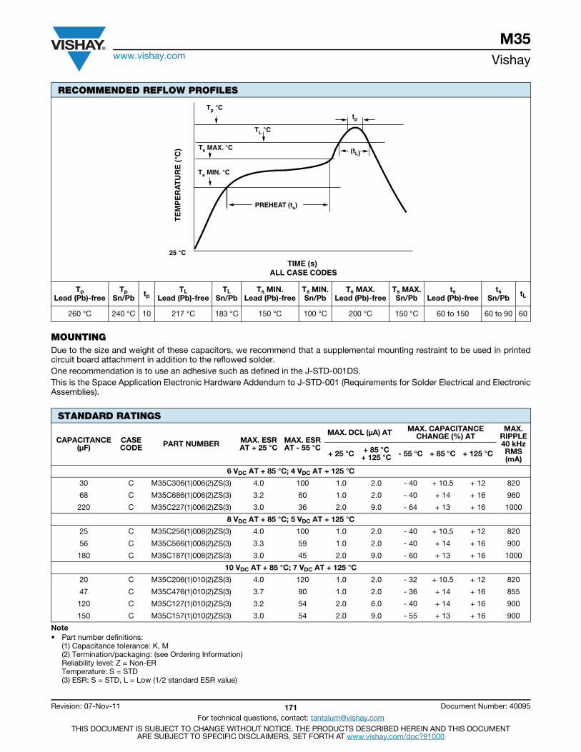
M35www.vishay.com Vishay
Revision: 07-Nov-11 171 Document Number: 40095
For technical questions, contact: [email protected] DOCUMENT IS SUBJECT TO CHANGE WITHOUT NOTICE. THE PRODUCTS DESCRIBED HEREIN AND THIS DOCUMENT
ARE SUBJECT TO SPECIFIC DISCLAIMERS, SET FORTH AT www.vishay.com/doc?91000
MOUNTINGDue to the size and weight of these capacitors, we recommend that a supplemental mounting restraint to be used in printedcircuit board attachment in addition to the reflowed solder.One recommendation is to use an adhesive such as defined in the J-STD-001DS.This is the Space Application Electronic Hardware Addendum to J-STD-001 (Requirements for Solder Electrical and ElectronicAssemblies).
RECOMMENDED REFLOW PROFILES
Tp Lead (Pb)-free
Tp Sn/Pb tp
TLLead (Pb)-free
TLSn/Pb
Ts MIN.Lead (Pb)-free
Ts MIN.Sn/Pb
Ts MAX.Lead (Pb)-free
Ts MAX.Sn/Pb
tsLead (Pb)-free
tsSn/Pb tL
260 °C 240 °C 10 217 °C 183 °C 150 °C 100 °C 200 °C 150 °C 60 to 150 60 to 90 60
STANDARD RATINGS
CAPACITANCE (μF)
CASECODE PART NUMBER MAX. ESR
AT + 25 °CMAX. ESRAT - 55 °C
MAX. DCL (μA) AT MAX. CAPACITANCECHANGE (%) AT
MAX.RIPPLE40 kHzRMS(mA)
+ 25 °C + 85 °C+ 125 °C - 55 °C + 85 °C + 125 °C
6 VDC AT + 85 °C; 4 VDC AT + 125 °C
30 C M35C306(1)006(2)ZS(3) 4.0 100 1.0 2.0 - 40 + 10.5 + 12 820
68 C M35C686(1)006(2)ZS(3) 3.2 60 1.0 2.0 - 40 + 14 + 16 960
220 C M35C227(1)006(2)ZS(3) 3.0 36 2.0 9.0 - 64 + 13 + 16 1000
8 VDC AT + 85 °C; 5 VDC AT + 125 °C
25 C M35C256(1)008(2)ZS(3) 4.0 100 1.0 2.0 - 40 + 10.5 + 12 820
56 C M35C566(1)008(2)ZS(3) 3.3 59 1.0 2.0 - 40 + 14 + 16 900
180 C M35C187(1)008(2)ZS(3) 3.0 45 2.0 9.0 - 60 + 13 + 16 1000
10 VDC AT + 85 °C; 7 VDC AT + 125 °C
20 C M35C206(1)010(2)ZS(3) 4.0 120 1.0 2.0 - 32 + 10.5 + 12 820
47 C M35C476(1)010(2)ZS(3) 3.7 90 1.0 2.0 - 36 + 14 + 16 855
120 C M35C127(1)010(2)ZS(3) 3.2 54 2.0 6.0 - 40 + 14 + 16 900
150 C M35C157(1)010(2)ZS(3) 3.0 54 2.0 9.0 - 55 + 13 + 16 900
Note• Part number definitions:
(1) Capacitance tolerance: K, M(2) Termination/packaging: (see Ordering Information)Reliability level: Z = Non-ERTemperature: S = STD(3) ESR: S = STD, L = Low (1/2 standard ESR value)
TE
MP
ER
AT
UR
E (
°C)
25 °C
TIME (s) ALL CASE CODES
Tp °C
TL °C
Ts MAX. °C
Ts MIN. °C
tp
(tL)
PREHEAT (ts)
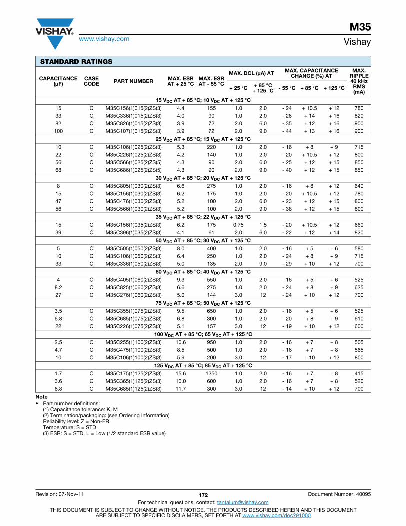
M35www.vishay.com Vishay
Revision: 07-Nov-11 172 Document Number: 40095
For technical questions, contact: [email protected] DOCUMENT IS SUBJECT TO CHANGE WITHOUT NOTICE. THE PRODUCTS DESCRIBED HEREIN AND THIS DOCUMENT
ARE SUBJECT TO SPECIFIC DISCLAIMERS, SET FORTH AT www.vishay.com/doc?91000
15 VDC AT + 85 °C; 10 VDC AT + 125 °C
15 C M35C156(1)015(2)ZS(3) 4.4 155 1.0 2.0 - 24 + 10.5 + 12 780 33 C M35C336(1)015(2)ZS(3) 4.0 90 1.0 2.0 - 28 + 14 + 16 820 82 C M35C826(1)015(2)ZS(3) 3.9 72 2.0 6.0 - 35 + 12 + 16 900100 C M35C107(1)015(2)ZS(3) 3.9 72 2.0 9.0 - 44 + 13 + 16 900
25 VDC AT + 85 °C; 15 VDC AT + 125 °C
10 C M35C106(1)025(2)ZS(3) 5.3 220 1.0 2.0 - 16 + 8 + 9 715 22 C M35C226(1)025(2)ZS(3) 4.2 140 1.0 2.0 - 20 + 10.5 + 12 800 56 C M35C566(1)025(2)ZS(5) 4.3 90 2.0 6.0 - 25 + 12 + 15 85068 C M35C686(1)025(2)ZS(5) 4.3 90 2.0 9.0 - 40 + 12 + 15 850
30 VDC AT + 85 °C; 20 VDC AT + 125 °C
8 C M35C805(1)030(2)ZS(3) 6.6 275 1.0 2.0 - 16 + 8 + 12 640 15 C M35C156(1)030(2)ZS(3) 6.2 175 1.0 2.0 - 20 + 10.5 + 12 780 47 C M35C476(1)030(2)ZS(3) 5.2 100 2.0 6.0 - 23 + 12 + 15 80056 C M35C566(1)030(2)ZS(3) 5.2 100 2.0 9.0 - 38 + 12 + 15 800
35 VDC AT + 85 °C; 22 VDC AT + 125 °C
15 C M35C156(1)035(2)ZS(3) 6.2 175 0.75 1.5 - 20 + 10.5 + 12 66039 C M35C396(1)035(2)ZS(3) 4.1 61 2.0 6.0 - 22 + 12 + 14 820
50 VDC AT + 85 °C; 30 VDC AT + 125 °C
5 C M35C505(1)050(2)ZS(3) 8.0 400 1.0 2.0 - 16 + 5 + 6 58010 C M35C106(1)050(2)ZS(3) 6.4 250 1.0 2.0 - 24 + 8 + 9 71533 C M35C336(1)050(2)ZS(3) 5.0 135 2.0 9.0 - 29 + 10 + 12 700
60 VDC AT + 85 °C; 40 VDC AT + 125 °C
4 C M35C405(1)060(2)ZS(3) 9.3 550 1.0 2.0 - 16 + 5 + 6 5258.2 C M35C825(1)060(2)ZS(3) 6.6 275 1.0 2.0 - 24 + 8 + 9 62527 C M35C276(1)060(2)ZS(3) 5.0 144 3.0 12 - 24 + 10 + 12 700
75 VDC AT + 85 °C; 50 VDC AT + 125 °C
3.5 C M35C355(1)075(2)ZS(3) 9.5 650 1.0 2.0 - 16 + 5 + 6 5256.8 C M35C685(1)075(2)ZS(3) 6.8 300 1.0 2.0 - 20 + 8 + 9 61022 C M35C226(1)075(2)ZS(3) 5.1 157 3.0 12 - 19 + 10 + 12 600
100 VDC AT + 85 °C; 65 VDC AT + 125 °C
2.5 C M35C255(1)100(2)ZS(3) 10.6 950 1.0 2.0 - 16 + 7 + 8 5054.7 C M35C475(1)100(2)ZS(3) 8.5 500 1.0 2.0 - 16 + 7 + 8 56510 C M35C106(1)100(2)ZS(3) 5.9 200 3.0 12 - 17 + 10 + 12 800
125 VDC AT + 85 °C; 85 VDC AT + 125 °C
1.7 C M35C175(1)125(2)ZS(3) 15.6 1250 1.0 2.0 - 16 + 7 + 8 4153.6 C M35C365(1)125(2)ZS(3) 10.0 600 1.0 2.0 - 16 + 7 + 8 5206.8 C M35C685(1)125(2)ZS(3) 11.7 300 3.0 12 - 14 + 10 + 12 700
STANDARD RATINGS
CAPACITANCE (μF)
CASECODE PART NUMBER MAX. ESR
AT + 25 °CMAX. ESRAT - 55 °C
MAX. DCL (μA) AT MAX. CAPACITANCECHANGE (%) AT
MAX.RIPPLE40 kHzRMS(mA)
+ 25 °C + 85 °C+ 125 °C - 55 °C + 85 °C + 125 °C
Note• Part number definitions:
(1) Capacitance tolerance: K, M(2) Termination/packaging: (see Ordering Information)Reliability level: Z = Non-ERTemperature: S = STD(3) ESR: S = STD, L = Low (1/2 standard ESR value)

M35www.vishay.com Vishay
Revision: 07-Nov-11 173 Document Number: 40095
For technical questions, contact: [email protected] DOCUMENT IS SUBJECT TO CHANGE WITHOUT NOTICE. THE PRODUCTS DESCRIBED HEREIN AND THIS DOCUMENT
ARE SUBJECT TO SPECIFIC DISCLAIMERS, SET FORTH AT www.vishay.com/doc?91000
PERFORMANCE CHARACTERISTICS OF M35 CAPACITORS
ELECTRICAL CHARACTERISTICSITEM PERFORMANCE CHARACTERISTICSOperating temperature range - 55 °C to + 125 °CCapacitor tolerance ± 20 %, ± 10 % at 120 HzCapacitance change (maximum)
Limits per Standard Ratings table. Measured per requirements of MIL-PRF-39006.ESRAC ripple currentDCL (maximum leakage current)Impedance (maximum)
Reverse voltage Reverse voltage shall be in accordance with MIL-PRF-39006/22.Units are capable of withstanding 3 V in reverse at + 85 °C for 125 h.
Surge voltage
Surge voltage shall be in accordance with MIL-PRF-39006.The DC rated surge voltage is the maximum voltage to which the capacitors should be subjectedunder any conditions. This includes transients and peak ripple at the highest line voltage. Thesurge voltage is 115 % of rated DC working voltage.
Life test The capacitors shall be capable of withstanding a 2000 h life test at 85 °C at rated voltage.
ENVIRONMENTAL CHARACTERISTICSITEM CONDITION COMMENTSHermeticity MIL-PRF-39006 The internal component has been tested to be compliant to the
hermeticity requirements of MIL-PRF-39006/22.The internal component has been tested to be compliant to themoisture resistance requirements of MIL-PRF-39006/22.The internal component has been tested to be compliant to thealtitude or reduced barometric pressure requirements ofMIL-PRF-39006/22 (150 000 feet).
Moisture resistance MIL-PRF-39006
Altitude/barometric pressure (reduced) MIL-PRF-39006
MECHANICAL CHARACTERISTICSITEM CONDITION COMMENTSThermal shock MIL-STD-202, Method 107, A Per MIL-PRF-39006, 30 cyclesShock MIL-STD-202, Method 213 Per MIL-PRF-39006, 500 g Vibration (high frequency) MIL-STD-202, Method 204 Per MIL-PRF-39006, 80 gVibration (random) MIL-STD-202, Method 214 Per MIL-PRF-39006, 53.79 g
Resistance to solder heat MIL-STD-202, Method 210 The capacitor must withstand solder dipping of the terminals at260 °C for 10 s. The capacitor must not be visibly damaged and theelectrical characteristics must not be affected.
Solderability ANSI J-STD-002 The terminations must be solderable per the requirements ofMIL-PRF-55365 para. 4.10
Part markings MIL-STD-1285 The part marking shall include Vishay name, trademark,capacitance, voltage, date code and lot symbol.
Weight (typical) in g 3.5
PAD DIMENSIONS in millimeters
CASE CODE A (MIN.) B (NOM.) C (NOM.) D (NOM.)C 22.7 14.7 4.0 6.4
STANDARD PACKAGING QUANTITYSERIES CASE CODE BULK/TUBE
M35 C 10 pcs
A
C B
D
C
Contents
DSCC 93026...................175
DSCC 10004...................178
DSCC 10011...................180
DSCC 06013-06016........185Tantalum Military
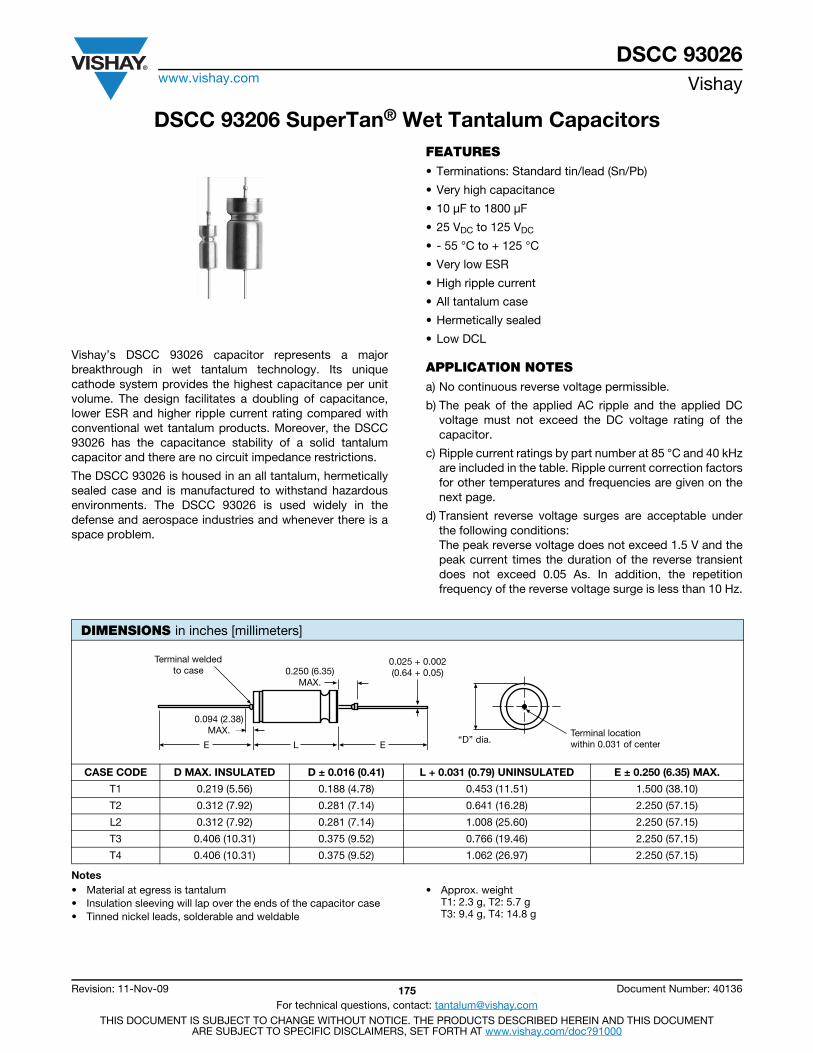
DSCC 93026www.vishay.com Vishay
Revision: 11-Nov-09 175 Document Number: 40136
For technical questions, contact: [email protected] DOCUMENT IS SUBJECT TO CHANGE WITHOUT NOTICE. THE PRODUCTS DESCRIBED HEREIN AND THIS DOCUMENT
ARE SUBJECT TO SPECIFIC DISCLAIMERS, SET FORTH AT www.vishay.com/doc?91000
DSCC 93206 SuperTan® Wet Tantalum Capacitors
Vishay’s DSCC 93026 capacitor represents a majorbreakthrough in wet tantalum technology. Its uniquecathode system provides the highest capacitance per unitvolume. The design facilitates a doubling of capacitance,lower ESR and higher ripple current rating compared withconventional wet tantalum products. Moreover, the DSCC93026 has the capacitance stability of a solid tantalumcapacitor and there are no circuit impedance restrictions.
The DSCC 93026 is housed in an all tantalum, hermeticallysealed case and is manufactured to withstand hazardousenvironments. The DSCC 93026 is used widely in thedefense and aerospace industries and whenever there is aspace problem.
FEATURES• Terminations: Standard tin/lead (Sn/Pb)
• Very high capacitance
• 10 μF to 1800 μF
• 25 VDC to 125 VDC
• - 55 °C to + 125 °C
• Very low ESR
• High ripple current
• All tantalum case
• Hermetically sealed
• Low DCL
APPLICATION NOTESa) No continuous reverse voltage permissible.
b) The peak of the applied AC ripple and the applied DCvoltage must not exceed the DC voltage rating of thecapacitor.
c) Ripple current ratings by part number at 85 °C and 40 kHzare included in the table. Ripple current correction factorsfor other temperatures and frequencies are given on thenext page.
d) Transient reverse voltage surges are acceptable underthe following conditions: The peak reverse voltage does not exceed 1.5 V and thepeak current times the duration of the reverse transientdoes not exceed 0.05 As. In addition, the repetitionfrequency of the reverse voltage surge is less than 10 Hz.
Notes• Material at egress is tantalum• Insulation sleeving will lap over the ends of the capacitor case• Tinned nickel leads, solderable and weldable
• Approx. weightT1: 2.3 g, T2: 5.7 gT3: 9.4 g, T4: 14.8 g
DIMENSIONS in inches [millimeters]
CASE CODE D MAX. INSULATED D ± 0.016 (0.41) L + 0.031 (0.79) UNINSULATED E ± 0.250 (6.35) MAX.
T1 0.219 (5.56) 0.188 (4.78) 0.453 (11.51) 1.500 (38.10)
T2 0.312 (7.92) 0.281 (7.14) 0.641 (16.28) 2.250 (57.15)
L2 0.312 (7.92) 0.281 (7.14) 1.008 (25.60) 2.250 (57.15)
T3 0.406 (10.31) 0.375 (9.52) 0.766 (19.46) 2.250 (57.15)
T4 0.406 (10.31) 0.375 (9.52) 1.062 (26.97) 2.250 (57.15)
“D” dia.Terminal locationwithin 0.031 of center
0.025 + 0.002(0.64 + 0.05)0.250 (6.35)
MAX.
0.094 (2.38)MAX.
E L E
Terminal weldedto case
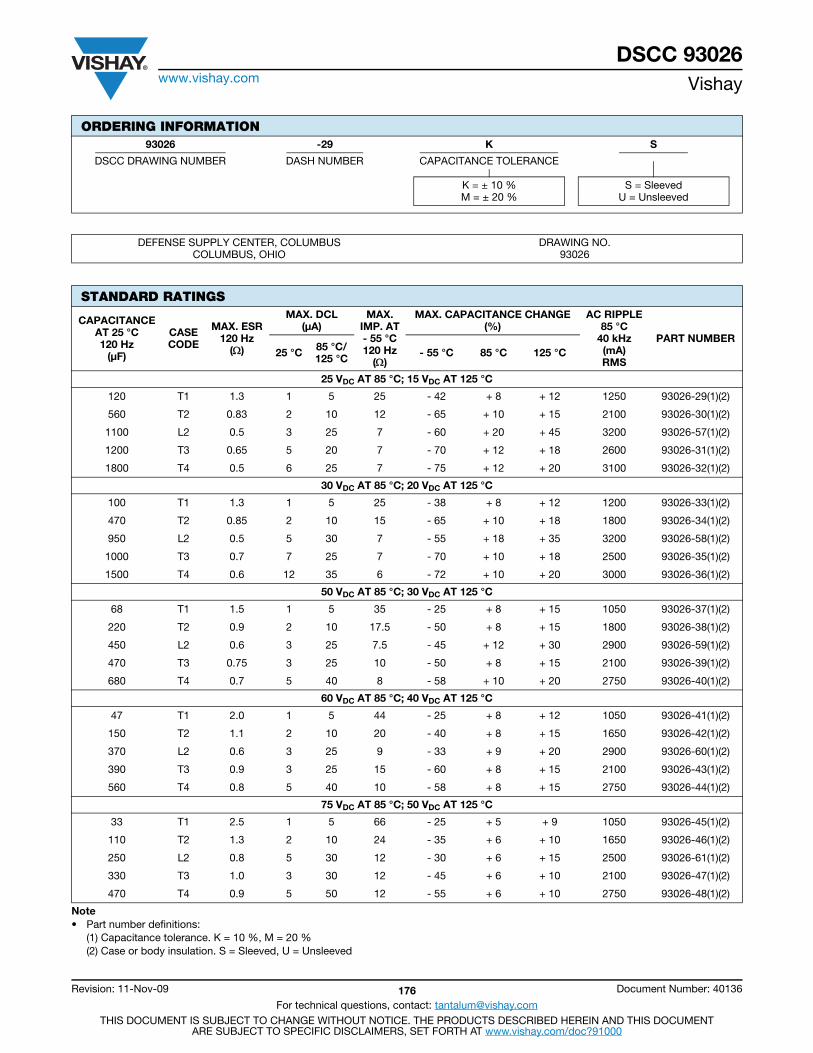
DSCC 93026www.vishay.com Vishay
Revision: 11-Nov-09 176 Document Number: 40136
For technical questions, contact: [email protected] DOCUMENT IS SUBJECT TO CHANGE WITHOUT NOTICE. THE PRODUCTS DESCRIBED HEREIN AND THIS DOCUMENT
ARE SUBJECT TO SPECIFIC DISCLAIMERS, SET FORTH AT www.vishay.com/doc?91000
ORDERING INFORMATION93026 -29 K S
DSCC DRAWING NUMBER DASH NUMBER CAPACITANCE TOLERANCE
K = ± 10 %M = ± 20 %
S = SleevedU = Unsleeved
DEFENSE SUPPLY CENTER, COLUMBUSCOLUMBUS, OHIO
DRAWING NO.93026
STANDARD RATINGS
CAPACITANCEAT 25 °C 120 Hz
(μF)
CASECODE
MAX. ESR120 Hz
()
MAX. DCL (μA)
MAX.IMP. AT- 55 °C120 Hz
()
MAX. CAPACITANCE CHANGE(%)
AC RIPPLE85 °C
40 kHz(mA)RMS
PART NUMBER25 °C 85 °C/
125 °C - 55 °C 85 °C 125 °C
25 VDC AT 85 °C; 15 VDC AT 125 °C
120 T1 1.3 1 5 25 - 42 + 8 + 12 1250 93026-29(1)(2)
560 T2 0.83 2 10 12 - 65 + 10 + 15 2100 93026-30(1)(2)
1100 L2 0.5 3 25 7 - 60 + 20 + 45 3200 93026-57(1)(2)
1200 T3 0.65 5 20 7 - 70 + 12 + 18 2600 93026-31(1)(2)
1800 T4 0.5 6 25 7 - 75 + 12 + 20 3100 93026-32(1)(2)
30 VDC AT 85 °C; 20 VDC AT 125 °C
100 T1 1.3 1 5 25 - 38 + 8 + 12 1200 93026-33(1)(2)
470 T2 0.85 2 10 15 - 65 + 10 + 18 1800 93026-34(1)(2)
950 L2 0.5 5 30 7 - 55 + 18 + 35 3200 93026-58(1)(2)
1000 T3 0.7 7 25 7 - 70 + 10 + 18 2500 93026-35(1)(2)
1500 T4 0.6 12 35 6 - 72 + 10 + 20 3000 93026-36(1)(2)
50 VDC AT 85 °C; 30 VDC AT 125 °C
68 T1 1.5 1 5 35 - 25 + 8 + 15 1050 93026-37(1)(2)
220 T2 0.9 2 10 17.5 - 50 + 8 + 15 1800 93026-38(1)(2)
450 L2 0.6 3 25 7.5 - 45 + 12 + 30 2900 93026-59(1)(2)
470 T3 0.75 3 25 10 - 50 + 8 + 15 2100 93026-39(1)(2)
680 T4 0.7 5 40 8 - 58 + 10 + 20 2750 93026-40(1)(2)
60 VDC AT 85 °C; 40 VDC AT 125 °C
47 T1 2.0 1 5 44 - 25 + 8 + 12 1050 93026-41(1)(2)
150 T2 1.1 2 10 20 - 40 + 8 + 15 1650 93026-42(1)(2)
370 L2 0.6 3 25 9 - 33 + 9 + 20 2900 93026-60(1)(2)
390 T3 0.9 3 25 15 - 60 + 8 + 15 2100 93026-43(1)(2)
560 T4 0.8 5 40 10 - 58 + 8 + 15 2750 93026-44(1)(2)
75 VDC AT 85 °C; 50 VDC AT 125 °C
33 T1 2.5 1 5 66 - 25 + 5 + 9 1050 93026-45(1)(2)
110 T2 1.3 2 10 24 - 35 + 6 + 10 1650 93026-46(1)(2)
250 L2 0.8 5 30 12 - 30 + 6 + 15 2500 93026-61(1)(2)
330 T3 1.0 3 30 12 - 45 + 6 + 10 2100 93026-47(1)(2)
470 T4 0.9 5 50 12 - 55 + 6 + 10 2750 93026-48(1)(2)
Note• Part number definitions:
(1) Capacitance tolerance. K = 10 %, M = 20 %(2) Case or body insulation. S = Sleeved, U = Unsleeved
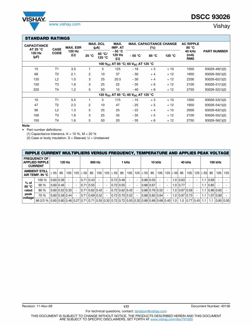
DSCC 93026www.vishay.com Vishay
Revision: 11-Nov-09 177 Document Number: 40136
For technical questions, contact: [email protected] DOCUMENT IS SUBJECT TO CHANGE WITHOUT NOTICE. THE PRODUCTS DESCRIBED HEREIN AND THIS DOCUMENT
ARE SUBJECT TO SPECIFIC DISCLAIMERS, SET FORTH AT www.vishay.com/doc?91000
100 VDC AT 85 °C; 65 VDC AT 125 °C
15 T1 3.5 1 5 125 - 18 + 3 + 10 1050 93026-49(1)(2)
68 T2 2.1 2 10 37 - 30 + 4 + 12 1650 93026-50(1)(2)
120 L2 1.0 3 25 20.5 - 30 + 4 + 12 2200 93026-62(1)(2)
150 T3 1.6 3 25 22 - 35 + 6 + 12 2100 93026-51(1)(2)
220 T4 1.2 5 50 15 - 40 + 6 + 12 2750 93026-52(1)(2)
125 VDC AT 85 °C; 85 VDC AT 125 °C
10 T1 5.5 1 5 175 - 15 + 3 + 10 1050 93026-53(1)(2)
47 T2 2.3 2 10 47 - 25 + 5 + 12 1650 93026-54(1)(2)
90 L2 1.3 5 25 25 - 22 + 4 + 15 2000 93026-63(1)(2)
100 T3 1.8 3 25 35 - 35 + 5 + 12 2100 93026-55(1)(2)
150 T4 1.6 5 50 20 - 35 + 6 + 12 2750 93026-56(1)(2)
RIPPLE CURRENT MULTIPLIERS VERSUS FREQUENCY, TEMPERATURE AND APPLIES PEAK VOLTAGEFREQUENCY OFAPPLIED RIPPLE
CURRENT120 Hz 800 Hz 1 kHz 10 kHz 40 kHz 100 kHz
AMBIENT STILLAIR TEMP. IN °C 55 85 105 125 55 85 105 125 55 85 105 125 55 85 105 125 55 85 105 125 55 85 105 125
% of85 °Cratedpeak
voltage
100 % 0.60 0.39 - - 0.71 0.43 - - 0.72 0.46 - - 0.88 0.55 - - 1.0 0.63 - - 1.1 0.69 - -
90 % 0.60 0.46 - - 0.71 0.55 - - 0.72 0.55 - - 0.88 0.67 - - 1.0 0.77 - - 1.1 0.85 - -
80 % 0.60 0.52 0.35 - 0.71 0.62 0.42 - 0.72 0.62 0.42 - 0.88 0.76 0.52 - 1.0 0.87 0.59 - 1.1 0.96 0.65 -
70 % 0.60 0.58 0.44 - 0.71 0.69 0.52 - 0.72 0.70 0.52 - 0.88 0.85 0.64 - 1.0 0.97 0.73 - 1.1 1.07 0.80 -
66 2/3 % 0.60 0.60 0.46 0.27 0.71 0.71 0.55 0.32 0.72 0.72 0.55 0.32 0.88 0.88 0.68 0.40 1.0 1.0 0.77 0.45 1.1 1.1 0.85 0.50
STANDARD RATINGS
CAPACITANCEAT 25 °C 120 Hz
(μF)
CASECODE
MAX. ESR120 Hz
()
MAX. DCL (μA)
MAX.IMP. AT- 55 °C120 Hz
()
MAX. CAPACITANCE CHANGE(%)
AC RIPPLE85 °C
40 kHz(mA)RMS
PART NUMBER25 °C 85 °C/
125 °C - 55 °C 85 °C 125 °C
Note• Part number definitions:
(1) Capacitance tolerance. K = 10 %, M = 20 %(2) Case or body insulation. S = Sleeved, U = Unsleeved
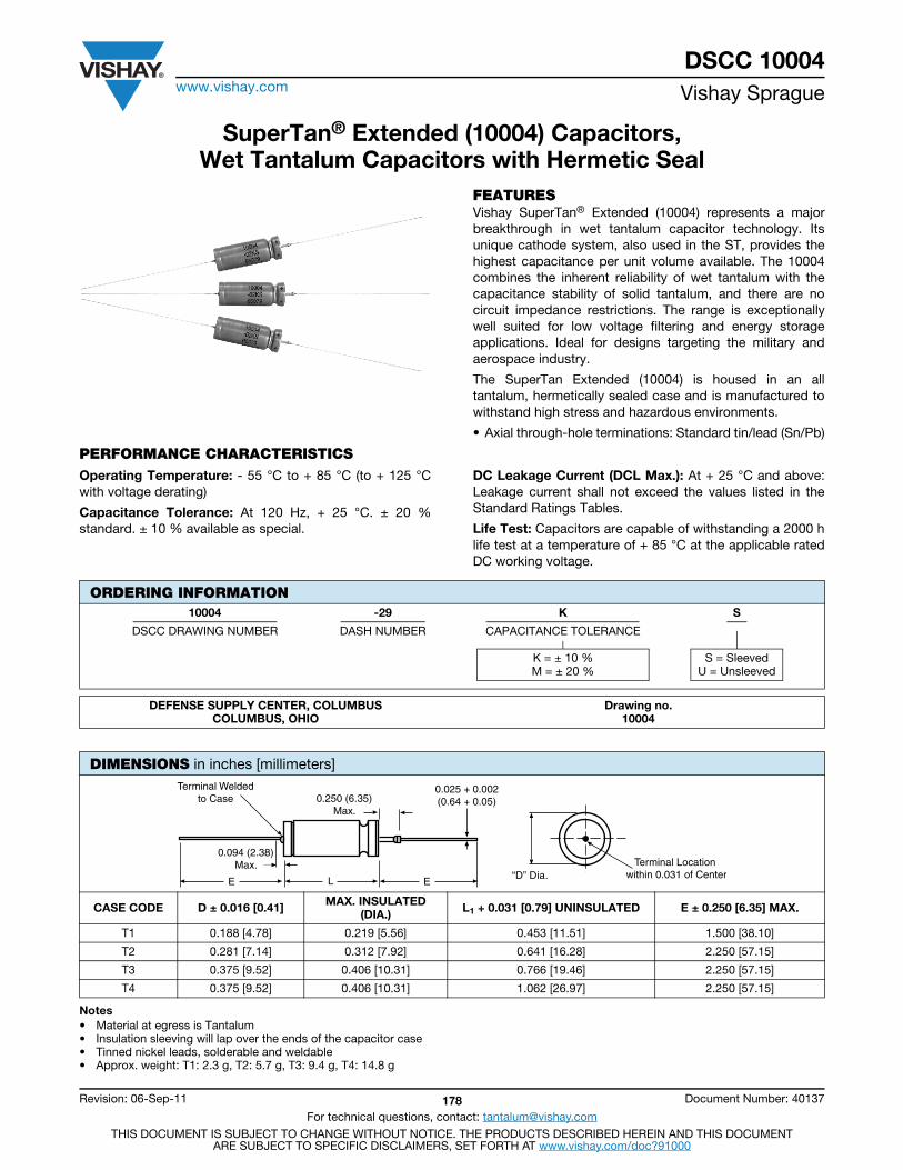
DSCC 10004www.vishay.com Vishay Sprague
Revision: 06-Sep-11 178 Document Number: 40137
For technical questions, contact: [email protected] DOCUMENT IS SUBJECT TO CHANGE WITHOUT NOTICE. THE PRODUCTS DESCRIBED HEREIN AND THIS DOCUMENT
ARE SUBJECT TO SPECIFIC DISCLAIMERS, SET FORTH AT www.vishay.com/doc?91000
SuperTan® Extended (10004) Capacitors, Wet Tantalum Capacitors with Hermetic Seal
FEATURESVishay SuperTan® Extended (10004) represents a majorbreakthrough in wet tantalum capacitor technology. Itsunique cathode system, also used in the ST, provides thehighest capacitance per unit volume available. The 10004combines the inherent reliability of wet tantalum with thecapacitance stability of solid tantalum, and there are nocircuit impedance restrictions. The range is exceptionallywell suited for low voltage filtering and energy storageapplications. Ideal for designs targeting the military andaerospace industry.
The SuperTan Extended (10004) is housed in an alltantalum, hermetically sealed case and is manufactured towithstand high stress and hazardous environments.
• Axial through-hole terminations: Standard tin/lead (Sn/Pb)
PERFORMANCE CHARACTERISTICSOperating Temperature: - 55 °C to + 85 °C (to + 125 °Cwith voltage derating)
Capacitance Tolerance: At 120 Hz, + 25 °C. ± 20 %standard. ± 10 % available as special.
DC Leakage Current (DCL Max.): At + 25 °C and above:Leakage current shall not exceed the values listed in theStandard Ratings Tables.
Life Test: Capacitors are capable of withstanding a 2000 hlife test at a temperature of + 85 °C at the applicable ratedDC working voltage.
Notes• Material at egress is Tantalum• Insulation sleeving will lap over the ends of the capacitor case• Tinned nickel leads, solderable and weldable• Approx. weight: T1: 2.3 g, T2: 5.7 g, T3: 9.4 g, T4: 14.8 g
ORDERING INFORMATION10004 -29 K S
DSCC DRAWING NUMBER DASH NUMBER CAPACITANCE TOLERANCE
K = ± 10 %M = ± 20 %
S = SleevedU = Unsleeved
DEFENSE SUPPLY CENTER, COLUMBUSCOLUMBUS, OHIO
Drawing no.10004
DIMENSIONS in inches [millimeters]
CASE CODE D ± 0.016 [0.41] MAX. INSULATED(DIA.) L1 + 0.031 [0.79] UNINSULATED E ± 0.250 [6.35] MAX.
T1 0.188 [4.78] 0.219 [5.56] 0.453 [11.51] 1.500 [38.10]
T2 0.281 [7.14] 0.312 [7.92] 0.641 [16.28] 2.250 [57.15]
T3 0.375 [9.52] 0.406 [10.31] 0.766 [19.46] 2.250 [57.15]
T4 0.375 [9.52] 0.406 [10.31] 1.062 [26.97] 2.250 [57.15]
“D” Dia.
Terminal Weldedto Case 0.250 (6.35)
Max.
0.094 (2.38)Max.
0.025 + 0.002(0.64 + 0.05)
E EL
Terminal Location within 0.031 of Center

DSCC 10004www.vishay.com Vishay Sprague
Revision: 06-Sep-11 179 Document Number: 40137
For technical questions, contact: [email protected] DOCUMENT IS SUBJECT TO CHANGE WITHOUT NOTICE. THE PRODUCTS DESCRIBED HEREIN AND THIS DOCUMENT
ARE SUBJECT TO SPECIFIC DISCLAIMERS, SET FORTH AT www.vishay.com/doc?91000
STANDARD RATINGS
CAPACITANCE(μF) VOLTAGE CASE
CODE
MAX. ESR AT120 Hz
()
TYP. ESR AT 1 kHz
()
MAX. DCL AT MAX. CAPACITANCE CHANGE AT Z
- 55 °C()
AC RIPPLE85 °C
40 kHzmA
RMS
PART NUMBER+ 25 °C
(μA)
+ 85 °C/ + 125 °C
(μA)
- 55 °C (%)
+ 85 °C (%)
+ 125 °C(%)
10 VDC AT + 85 ºC, SURGE = 11.5 VDC; 7 VDC AT + 125 ºC
4700 10 T3 0.35 < 0.200 16 100 - 80 10 20 3.50 4000 10004-01(1)(2)
10 000 10 T4 0.25 < 0.100 25 150 - 85 20 35 3.00 5000 10004-02(1)(2)
16 VDC AT + 85 ºC, SURGE = 18.4 VDC; 11 VDC AT + 125 ºC3300 16 T3 0.35 < 0.200 16 100 - 80 10 15 3.50 4000 10004-03(1)(2)
6000 16 T4 0.30 < 0.150 25 150 - 80 15 20 3.00 4500 10004-04(1)(2)
25 VDC AT + 85 ºC, SURGE = 28.8 VDC; 15 VDC AT + 125 ºC
4000 25 T4 0.35 25 125 - 80 15 20 5.00 4250 10004-05(1)(2)
30 VDC AT + 85 ºC, SURGE = 34.5 VDC; 20 VDC AT + 125 ºC
3300 30 T4 0.35 < 0.200 25 125 - 80 20 25 4.00 2750 10004-06(1)(2)
35 VDC AT + 85 ºC, SURGE = 40.3 VDC; 22 VDC AT + 125 ºC
2500 35 T4 Preliminary value, contact marketing n/a
50 VDC AT + 85 ºC, SURGE = 57.5 VDC; 30 VDC AT + 125 ºC1500 50 T4 0.35 < 0.215 15 110 - 70 20 20 6.00 3500 10004-08(1)(2)
2200 50 T4 0.60 < 0.400 25 125 - 80 25 30 4.50 3000 10004-15(1)(2)
60 VDC AT + 85 ºC, SURGE = 69 VDC; 40 VDC AT + 125 ºC
1000 60 T4 0.50 < 0.300 20 120 - 40 10 15 5.50 3500 10004-09(1)(2)
75 VDC AT + 85 ºC, SURGE = 86.3 VDC; 50 VDC AT + 125 ºC
180 75 T2 1.50 < 0.500 5 25 - 35 15 20 30.00 2000 10004-10(1)(2)
470 75 T3 0.60 < 0.325 25 100 - 45 10 25 10.00 3000 10004-11(1)(2)
750 75 T4 0.50 < 0.400 20 120 - 35 10 15 6.50 3500 10004-12(1)(2)
100 VDC AT + 85 ºC, SURGE = 115 VDC; 65 VDC AT + 125 ºC
400 100 T4 0.70 < 0.400 10 120 - 40 6 12 15.00 3000 10004-13(1)(2)
125 VDC AT + 85 ºC, SURGE = 144 VDC; 85 VDC AT + 125 ºC
240 125 T4 0.80 < 0.600 15 150 - 35 6 12 20.00 2500 10004-14(1)(2)
Note• Part number definitions:
(1) K = 10 %M = 20 %
(2) D = sleeved or insulatedU = unsleeved
RIPPLE CURRENT MULTIPLIERS VS. FREQUENCY, TEMPERATURE AND APPLIES PEAK VOLTAGEFREQUENCYOF APPLIED RIPPLE
CURRENT120 Hz 800 Hz 1 kHz 10 kHz 40 kHz 100 kHz
AMBIENT STILL AIR TEMP. IN °C 55 85 105 125 55 85 105 125 55 85 105 125 55 85 105 125 55 85 105 125 55 85 105 125
% of 85 °C rated peak
voltage
100 % 0.60 0.39 - - 0.71 0.43 - - 0.72 0.46 - - 0.88 0.55 - - 1.0 0.63 - - 1.1 0.69 - -
90 % 0.60 0.46 - - 0.71 0.55 - - 0.72 0.55 - - 0.88 0.67 - - 1.0 0.77 - - 1.1 0.85 - -
80 % 0.60 0.52 0.35 - 0.71 0.62 0.42 - 0.72 0.62 0.42 - 0.88 0.76 0.52 - 1.0 0.87 0.59 - 1.1 0.96 0.65 -
70 % 0.60 0.58 0.44 - 0.71 0.69 0.52 - 0.72 0.70 0.52 - 0.88 0.85 0.64 - 1.0 0.97 0.73 - 1.1 1.07 0.80 -
66 2/3 % 0.60 0.60 0.46 0.27 0.71 0.71 0.55 0.32 0.72 0.72 0.55 0.32 0.88 0.88 0.68 0.40 1.0 1.0 0.77 0.45 1.1 1.1 0.85 0.50
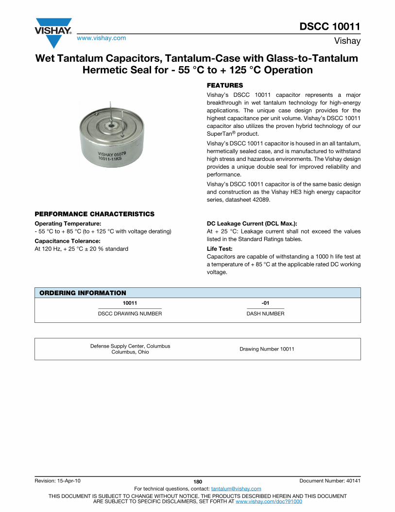
DSCC 10011www.vishay.com Vishay
Revision: 15-Apr-10 180 Document Number: 40141
For technical questions, contact: [email protected] DOCUMENT IS SUBJECT TO CHANGE WITHOUT NOTICE. THE PRODUCTS DESCRIBED HEREIN AND THIS DOCUMENT
ARE SUBJECT TO SPECIFIC DISCLAIMERS, SET FORTH AT www.vishay.com/doc?91000
Wet Tantalum Capacitors, Tantalum-Case with Glass-to-Tantalum Hermetic Seal for - 55 °C to + 125 °C Operation
FEATURESVishay’s DSCC 10011 capacitor represents a majorbreakthrough in wet tantalum technology for high-energyapplications. The unique case design provides for thehighest capacitance per unit volume. Vishay’s DSCC 10011capacitor also utilizes the proven hybrid technology of ourSuperTan® product.
Vishay’s DSCC 10011 capacitor is housed in an all tantalum,hermetically sealed case, and is manufactured to withstandhigh stress and hazardous environments. The Vishay designprovides a unique double seal for improved reliability andperformance.
Vishay’s DSCC 10011 capacitor is of the same basic designand construction as the Vishay HE3 high energy capacitorseries, datasheet 42089.
PERFORMANCE CHARACTERISTICSOperating Temperature:- 55 °C to + 85 °C (to + 125 °C with voltage derating)
Capacitance Tolerance:At 120 Hz, + 25 °C ± 20 % standard
DC Leakage Current (DCL Max.):At + 25 °C: Leakage current shall not exceed the valueslisted in the Standard Ratings tables.
Life Test:Capacitors are capable of withstanding a 1000 h life test ata temperature of + 85 °C at the applicable rated DC workingvoltage.
ORDERING INFORMATION
10011 -01
DSCC DRAWING NUMBER DASH NUMBER
Defense Supply Center, ColumbusColumbus, Ohio Drawing Number 10011
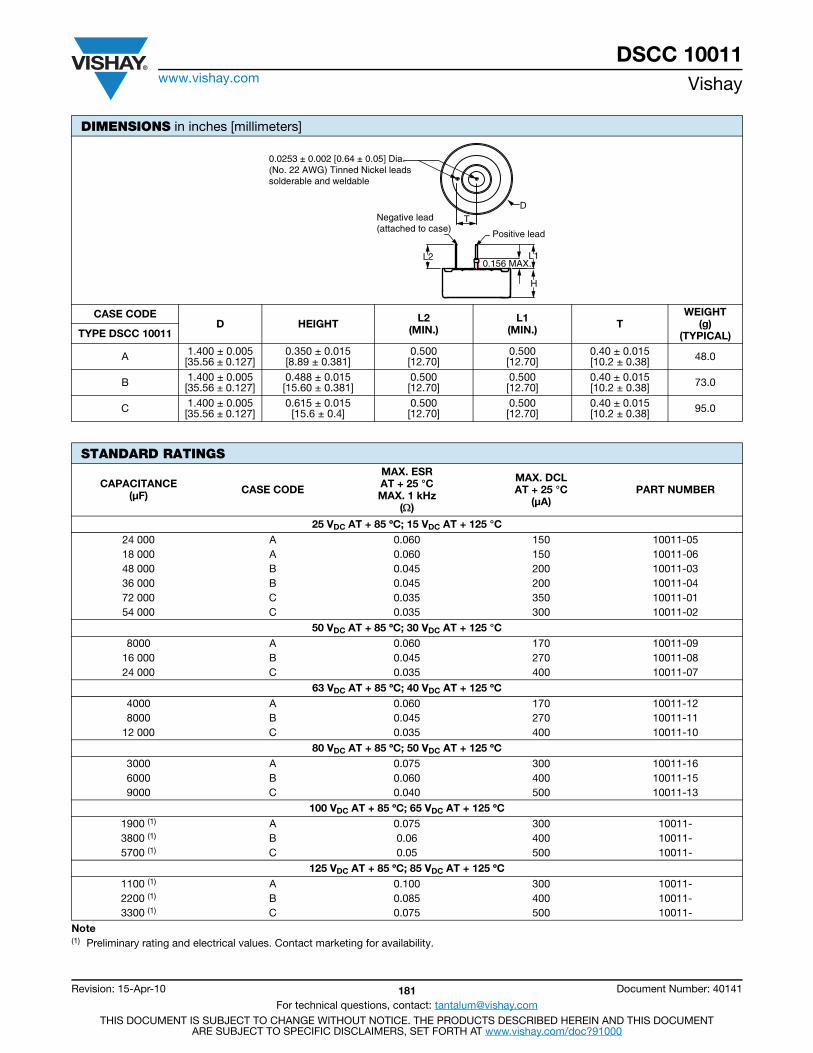
DSCC 10011www.vishay.com Vishay
Revision: 15-Apr-10 181 Document Number: 40141
For technical questions, contact: [email protected] DOCUMENT IS SUBJECT TO CHANGE WITHOUT NOTICE. THE PRODUCTS DESCRIBED HEREIN AND THIS DOCUMENT
ARE SUBJECT TO SPECIFIC DISCLAIMERS, SET FORTH AT www.vishay.com/doc?91000
DIMENSIONS in inches [millimeters]
CASE CODE D HEIGHT L2
(MIN.) L1
(MIN.) TWEIGHT
(g) (TYPICAL) TYPE DSCC 10011
A 1.400 ± 0.005 [35.56 ± 0.127]
0.350 ± 0.015[8.89 ± 0.381]
0.500[12.70]
0.500[12.70]
0.40 ± 0.015[10.2 ± 0.38] 48.0
B 1.400 ± 0.005 [35.56 ± 0.127]
0.488 ± 0.015[15.60 ± 0.381]
0.500[12.70]
0.500[12.70]
0.40 ± 0.015[10.2 ± 0.38] 73.0
C 1.400 ± 0.005 [35.56 ± 0.127]
0.615 ± 0.015[15.6 ± 0.4]
0.500[12.70]
0.500[12.70]
0.40 ± 0.015[10.2 ± 0.38] 95.0
STANDARD RATINGS
CAPACITANCE(μF) CASE CODE
MAX. ESR AT + 25 °CMAX. 1 kHz
()
MAX. DCLAT + 25 °C
(μA)PART NUMBER
25 VDC AT + 85 ºC; 15 VDC AT + 125 °C24 000 A 0.060 150 10011-0518 000 A 0.060 150 10011-0648 000 B 0.045 200 10011-0336 000 B 0.045 200 10011-0472 000 C 0.035 350 10011-0154 000 C 0.035 300 10011-02
50 VDC AT + 85 ºC; 30 VDC AT + 125 °C8000 A 0.060 170 10011-09
16 000 B 0.045 270 10011-0824 000 C 0.035 400 10011-07
63 VDC AT + 85 ºC; 40 VDC AT + 125 ºC4000 A 0.060 170 10011-128000 B 0.045 270 10011-11
12 000 C 0.035 400 10011-10
80 VDC AT + 85 ºC; 50 VDC AT + 125 ºC3000 A 0.075 300 10011-166000 B 0.060 400 10011-159000 C 0.040 500 10011-13
100 VDC AT + 85 ºC; 65 VDC AT + 125 ºC1900 (1) A 0.075 300 10011-3800 (1) B 0.06 400 10011-5700 (1) C 0.05 500 10011-
125 VDC AT + 85 ºC; 85 VDC AT + 125 ºC1100 (1) A 0.100 300 10011-2200 (1) B 0.085 400 10011-3300 (1) C 0.075 500 10011-
Note(1) Preliminary rating and electrical values. Contact marketing for availability.
D
Positive lead
L2
H
L1
T
0.0253 ± 0.002 [0.64 ± 0.05] Dia.(No. 22 AWG) Tinned Nickel leadssolderable and weldable
Negative lead(attached to case)
0.156 MAX..
DSCC 10011www.vishay.com Vishay
Revision: 15-Apr-10 182 Document Number: 40141
For technical questions, contact: [email protected] DOCUMENT IS SUBJECT TO CHANGE WITHOUT NOTICE. THE PRODUCTS DESCRIBED HEREIN AND THIS DOCUMENT
ARE SUBJECT TO SPECIFIC DISCLAIMERS, SET FORTH AT www.vishay.com/doc?91000
PERFORMANCE CHARACTERISTICS OF HIGH ENERGY CAPACITORS
ELECTRICAL PERFORMANCE CHARACTERISTICSITEM PERFORMANCE CHARACTERISTICS
Operating temperature range - 55 °C to + 85 °C (to + 125 °C with voltage derating)
Capacitor tolerance ± 20 % at 120 Hz
ESR Limits per Standard Ratings table
DC leakage current (DCL max.) At 25 °C the leakage current shall not exceed values listed in the Standard Rating table.
Reverse voltage No continuous reverse voltage permitted
Surge voltage The test shall be at 1000 cycles at 110 % of rated voltage at 85 °C. A cycle consists of a 30 scharge and a 330 s discharge through 100 W resistor.
Life test at + 85 °C 1000 h at + 85 °C
ENVIRONMENTAL CHARACTERISTICSITEM TEST AND CONDITIONS COMMENTS
Hermeticity MIL-STD-202, method 112 C/IIIa The capacitor shall be hermetically sealed such that the case does notleak electrolyte or vent any gas when exposed to a vacuum.
Moisture resistance MIL-STD-202, method 106 6 V polarity
Altitude MIL-STD-202, method 105 C,test condition D 100 000 feet test
MECHANICAL PERFORMANCE CHARACTERISTICSITEM TEST AND CONDITIONS COMMENTS
Thermal shock MIL-STD-202, method 107 G Test condition A
ShockMIL-STD-202, method 213 B test condition G
11 ms, 50 g
Vibration - high frequencyMIL-STD-202, method 204 D test condition D
12 sweeps/axis, 20 g peak
Vibration - randomMIL-STD-202, method 214 A test condition I, D
1.5 h/axis, 12 g
Resistance to solder heat MIL-STD-202, method 210 FThe capacitor must withstand solder dipping of the terminals at 260 °Cfor 10 s. The capacitor must not be visibly damaged and the electricalcharacteristics must not be affected.
Solderability MIL-STD-202, method 208
Terminal strength MIL-STD-202, method 211 AThe capacitor terminals must withstand a 5 pound pull test for 5 s to 10 s.The capacitor must not be visibly damaged and the electricalcharacteristics must not be affected.
Resistance to solvents MIL-STD-202, method 215 J The capacitor shall be permanently and legibly marked on thecircumference of the case. The markings shall be resistant to solvents.
Weight (mass) See dimensions table
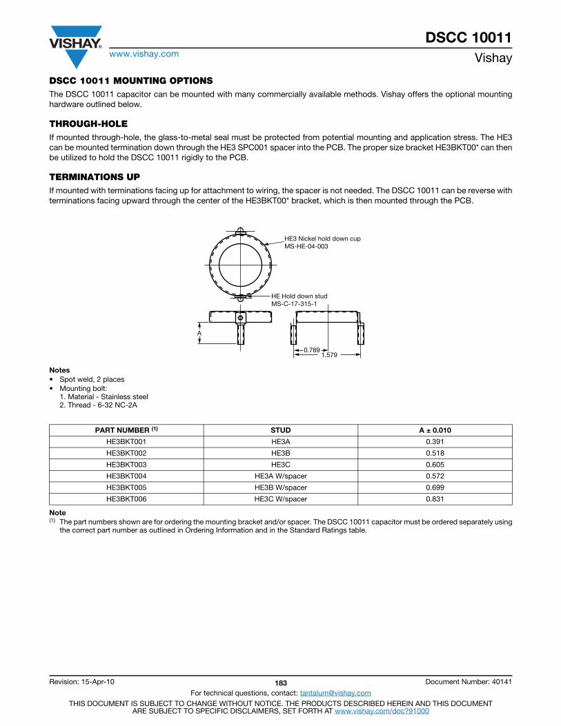
DSCC 10011www.vishay.com Vishay
Revision: 15-Apr-10 183 Document Number: 40141
For technical questions, contact: [email protected] DOCUMENT IS SUBJECT TO CHANGE WITHOUT NOTICE. THE PRODUCTS DESCRIBED HEREIN AND THIS DOCUMENT
ARE SUBJECT TO SPECIFIC DISCLAIMERS, SET FORTH AT www.vishay.com/doc?91000
DSCC 10011 MOUNTING OPTIONSThe DSCC 10011 capacitor can be mounted with many commercially available methods. Vishay offers the optional mountinghardware outlined below.
THROUGH-HOLEIf mounted through-hole, the glass-to-metal seal must be protected from potential mounting and application stress. The HE3can be mounted termination down through the HE3 SPC001 spacer into the PCB. The proper size bracket HE3BKT00* can thenbe utilized to hold the DSCC 10011 rigidly to the PCB.
TERMINATIONS UPIf mounted with terminations facing up for attachment to wiring, the spacer is not needed. The DSCC 10011 can be reverse withterminations facing upward through the center of the HE3BKT00* bracket, which is then mounted through the PCB.
Notes• Spot weld, 2 places• Mounting bolt:
1. Material - Stainless steel2. Thread - 6-32 NC-2A
Note(1) The part numbers shown are for ordering the mounting bracket and/or spacer. The DSCC 10011 capacitor must be ordered separately using
the correct part number as outlined in Ordering Information and in the Standard Ratings table.
PART NUMBER (1) STUD A ± 0.010
HE3BKT001 HE3A 0.391
HE3BKT002 HE3B 0.518
HE3BKT003 HE3C 0.605
HE3BKT004 HE3A W/spacer 0.572
HE3BKT005 HE3B W/spacer 0.699
HE3BKT006 HE3C W/spacer 0.831
HE3 Nickel hold down cupMS-HE-04-003
HE Hold down studMS-C-17-315-1
A
0.7891.579
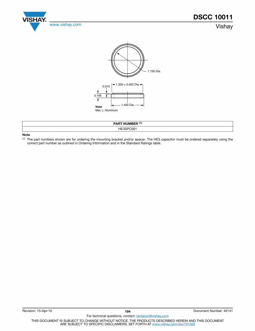
DSCC 10011www.vishay.com Vishay
Revision: 15-Apr-10 184 Document Number: 40141
For technical questions, contact: [email protected] DOCUMENT IS SUBJECT TO CHANGE WITHOUT NOTICE. THE PRODUCTS DESCRIBED HEREIN AND THIS DOCUMENT
ARE SUBJECT TO SPECIFIC DISCLAIMERS, SET FORTH AT www.vishay.com/doc?91000
Note(1) The part numbers shown are for ordering the mounting bracket and/or spacer. The HE3 capacitor must be ordered separately using the
correct part number as outlined in Ordering Information and in the Standard Ratings table.
PART NUMBER (1)
HE3SPC001
1.150 Dia.
1.326 ± 0.002 Dia.
1.400 Dia.
0.195
0.015
NoteMat. L: Aluminum
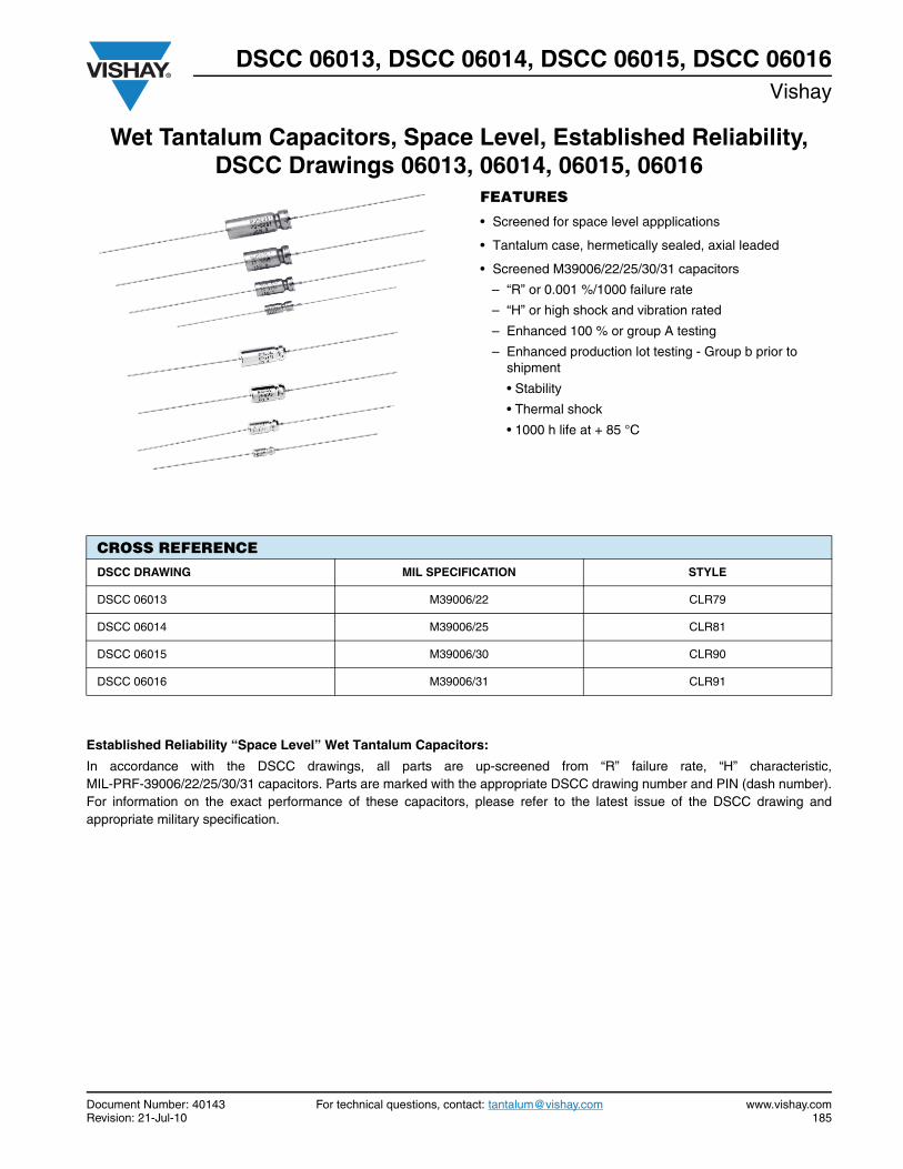
DSCC 06013, DSCC 06014, DSCC 06015, DSCC 06016Vishay
Document Number: 40143 For technical questions, contact: [email protected] www.vishay.comRevision: 21-Jul-10 185
Wet Tantalum Capacitors, Space Level, Established Reliability, DSCC Drawings 06013, 06014, 06015, 06016
FEATURES
• Screened for space level appplications
• Tantalum case, hermetically sealed, axial leaded
• Screened M39006/22/25/30/31 capacitors
– “R” or 0.001 %/1000 failure rate
– “H” or high shock and vibration rated
– Enhanced 100 % or group A testing
– Enhanced production lot testing - Group b prior to shipment
• Stability
• Thermal shock
• 1000 h life at + 85 °C
Established Reliability “Space Level” Wet Tantalum Capacitors:
In accordance with the DSCC drawings, all parts are up-screened from “R” failure rate, “H” characteristic,MIL-PRF-39006/22/25/30/31 capacitors. Parts are marked with the appropriate DSCC drawing number and PIN (dash number).For information on the exact performance of these capacitors, please refer to the latest issue of the DSCC drawing andappropriate military specification.
CROSS REFERENCE
DSCC DRAWING MIL SPECIFICATION STYLE
DSCC 06013 M39006/22 CLR79
DSCC 06014 M39006/25 CLR81
DSCC 06015 M39006/30 CLR90
DSCC 06016 M39006/31 CLR91
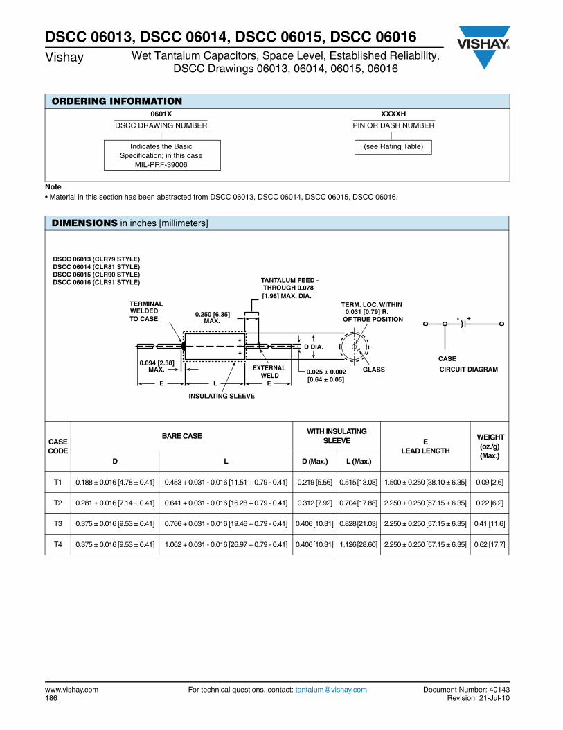
www.vishay.com For technical questions, contact: [email protected] Document Number: 40143186 Revision: 21-Jul-10
DSCC 06013, DSCC 06014, DSCC 06015, DSCC 06016Vishay Wet Tantalum Capacitors, Space Level, Established Reliability,
DSCC Drawings 06013, 06014, 06015, 06016
Note• Material in this section has been abstracted from DSCC 06013, DSCC 06014, DSCC 06015, DSCC 06016.
ORDERING INFORMATION0601X XXXXH
DSCC DRAWING NUMBER PIN OR DASH NUMBER
Indicates the Basic Specification; in this case
MIL-PRF-39006
(see Rating Table)
DIMENSIONS in inches [millimeters]
CASE CODE
BARE CASE WITH INSULATING
SLEEVE E LEAD LENGTH
WEIGHT (oz./g) (Max.)
D L D (Max.) L (Max.)
T1 0.188 ± 0.016 [4.78 ± 0.41] 0.453 + 0.031 - 0.016 [11.51 + 0.79 - 0.41] 0.219 [5.56] 0.515 [13.08] 1.500 ± 0.250 [38.10 ± 6.35] 0.09 [2.6]
T2 0.281 ± 0.016 [7.14 ± 0.41] 0.641 + 0.031 - 0.016 [16.28 + 0.79 - 0.41] 0.312 [7.92] 0.704 [17.88] 2.250 ± 0.250 [57.15 ± 6.35] 0.22 [6.2]
T3 0.375 ± 0.016 [9.53 ± 0.41] 0.766 + 0.031 - 0.016 [19.46 + 0.79 - 0.41] 0.406 [10.31] 0.828 [21.03] 2.250 ± 0.250 [57.15 ± 6.35] 0.41 [11.6]
T4 0.375 ± 0.016 [9.53 ± 0.41] 1.062 + 0.031 - 0.016 [26.97 + 0.79 - 0.41] 0.406 [10.31] 1.126 [28.60] 2.250 ± 0.250 [57.15 ± 6.35] 0.62 [17.7]
EXTERNAL WELD
D DIA.
0.094 [2.38]MAX.
TERMINALWELDEDTO CASE
INSULATING SLEEVE
TERM. LOC. WITHIN0.031 [0.79] R.
OF TRUE POSITION0.250 [6.35]
MAX.
TANTALUM FEED -THROUGH 0.078[1.98] MAX. DIA.
ELE
GLASS
CASE
CIRCUIT DIAGRAM0.025 ± 0.002[0.64 ± 0.05]
- +
DSCC 06013 (CLR79 STYLE)DSCC 06014 (CLR81 STYLE)DSCC 06015 (CLR90 STYLE)DSCC 06016 (CLR91 STYLE)
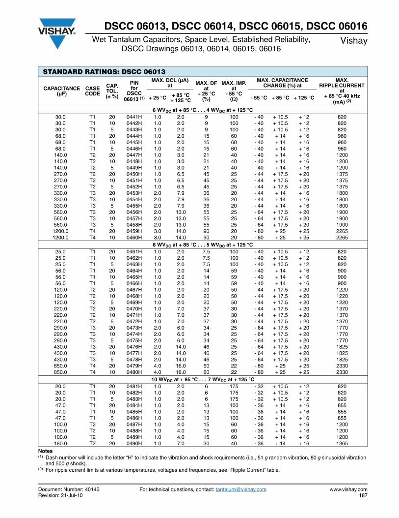
Document Number: 40143 For technical questions, contact: [email protected] www.vishay.comRevision: 21-Jul-10 187
DSCC 06013, DSCC 06014, DSCC 06015, DSCC 06016Wet Tantalum Capacitors, Space Level, Established Reliability,
DSCC Drawings 06013, 06014, 06015, 06016Vishay
Notes(1) Dash number will include the letter “H” to indicate the vibration and shock requirements (i.e., 51 g random vibration, 80 g sinusoidal vibration
and 500 g shock).(2) For ripple current limits at various temperatures, voltages and frequencies, see “Ripple Current” table.
STANDARD RATINGS: DSCC 06013
CAPACITANCE (µF)
CASE CODE
CAP. TOL. (± %)
PIN for
DSCC 06013 (1)
MAX. DCL (µA)at MAX. DF
at + 25 °C
(%)
MAX. IMP.at
- 55 °C()
MAX. CAPACITANCE CHANGE (%) at
MAX. RIPPLE CURRENT
at + 85 °C 40 kHz
(mA) (2)+ 25 °C + 85 °C
+ 125 °C - 55 °C + 85 °C + 125 °C
6 WVDC at + 85 °C . . . 4 WVDC at + 125 °C 30.0 T1 20 0441H 1.0 2.0 9 100 - 40 + 10.5 + 12 820 30.0 T1 10 0442H 1.0 2.0 9 100 - 40 + 10.5 + 12 820 30.0 T1 5 0443H 1.0 2.0 9 100 - 40 + 10.5 + 12 820 68.0 T1 20 0444H 1.0 2.0 15 60 - 40 + 14 + 16 960 68.0 T1 10 0445H 1.0 2.0 15 60 - 40 + 14 + 16 960 68.0 T1 5 0446H 1.0 2.0 15 60 - 40 + 14 + 16 960 140.0 T2 20 0447H 1.0 3.0 21 40 - 40 + 14 + 16 1200 140.0 T2 10 0448H 1.0 3.0 21 40 - 40 + 14 + 16 1200 140.0 T2 5 0449H 1.0 3.0 21 40 - 40 + 14 + 16 1200 270.0 T2 20 0450H 1.0 6.5 45 25 - 44 + 17.5 + 20 1375 270.0 T2 10 0451H 1.0 6.5 45 25 - 44 + 17.5 + 20 1375 270.0 T2 5 0452H 1.0 6.5 45 25 - 44 + 17.5 + 20 1375 330.0 T3 20 0453H 2.0 7.9 36 20 - 44 + 14 + 16 1800 330.0 T3 10 0454H 2.0 7.9 36 20 - 44 + 14 + 16 1800 330.0 T3 5 0455H 2.0 7.9 36 20 - 44 + 14 + 16 1800 560.0 T3 20 0456H 2.0 13.0 55 25 - 64 + 17.5 + 20 1900 560.0 T3 10 0457H 2.0 13.0 55 25 - 64 + 17.5 + 20 1900 560.0 T3 5 0458H 2.0 13.0 55 25 - 64 + 17.5 + 20 1900 1200.0 T4 20 0459H 3.0 14.0 90 20 - 80 + 25 + 25 2265 1200.0 T4 10 0460H 3.0 14.0 90 20 - 80 + 25 + 25 2265
8 WVDC at + 85 °C . . . 5 WVDC at + 125 °C 25.0 T1 20 0461H 1.0 2.0 7.5 100 - 40 + 10.5 + 12 820 25.0 T1 10 0462H 1.0 2.0 7.5 100 - 40 + 10.5 + 12 820 25.0 T1 5 0463H 1.0 2.0 7.5 100 - 40 + 10.5 + 12 820 56.0 T1 20 0464H 1.0 2.0 14 59 - 40 + 14 + 16 900 56.0 T1 10 0465H 1.0 2.0 14 59 - 40 + 14 + 16 900 56.0 T1 5 0466H 1.0 2.0 14 59 - 40 + 14 + 16 900 120.0 T2 20 0467H 1.0 2.0 20 50 - 44 + 17.5 + 20 1220 120.0 T2 10 0468H 1.0 2.0 20 50 - 44 + 17.5 + 20 1220 120.0 T2 5 0469H 1.0 2.0 20 50 - 44 + 17.5 + 20 1220 220.0 T2 20 0470H 1.0 7.0 37 30 - 44 + 17.5 + 20 1370 220.0 T2 10 0471H 1.0 7.0 37 30 - 44 + 17.5 + 20 1370 220.0 T2 5 0472H 1.0 7.0 37 30 - 44 + 17.5 + 20 1370 290.0 T3 20 0473H 2.0 6.0 34 25 - 64 + 17.5 + 20 1770 290.0 T3 10 0474H 2.0 6.0 34 25 - 64 + 17.5 + 20 1770 290.0 T3 5 0475H 2.0 6.0 34 25 - 64 + 17.5 + 20 1770 430.0 T3 20 0476H 2.0 14.0 46 25 - 64 + 17.5 + 20 1825 430.0 T3 10 0477H 2.0 14.0 46 25 - 64 + 17.5 + 20 1825 430.0 T3 5 0478H 2.0 14.0 46 25 - 64 + 17.5 + 20 1825 850.0 T4 20 0479H 4.0 16.0 60 22 - 80 + 25 + 25 2330 850.0 T4 10 0480H 4.0 16.0 60 22 - 80 + 25 + 25 2330
10 WVDC at + 85 °C . . . 7 WVDC at + 125 °C 20.0 T1 20 0481H 1.0 2.0 6 175 - 32 + 10.5 + 12 820 20.0 T1 10 0482H 1.0 2.0 6 175 - 32 + 10.5 + 12 820 20.0 T1 5 0483H 1.0 2.0 6 175 - 32 + 10.5 + 12 820 47.0 T1 20 0484H 1.0 2.0 13 100 - 36 + 14 + 16 855 47.0 T1 10 0485H 1.0 2.0 13 100 - 36 + 14 + 16 855 47.0 T1 5 0486H 1.0 2.0 13 100 - 36 + 14 + 16 855 100.0 T2 20 0487H 1.0 4.0 15 60 - 36 + 14 + 16 1200 100.0 T2 10 0488H 1.0 4.0 15 60 - 36 + 14 + 16 1200 100.0 T2 5 0489H 1.0 4.0 15 60 - 36 + 14 + 16 1200 180.0 T2 20 0490H 1.0 7.0 30 40 - 36 + 14 + 16 1365
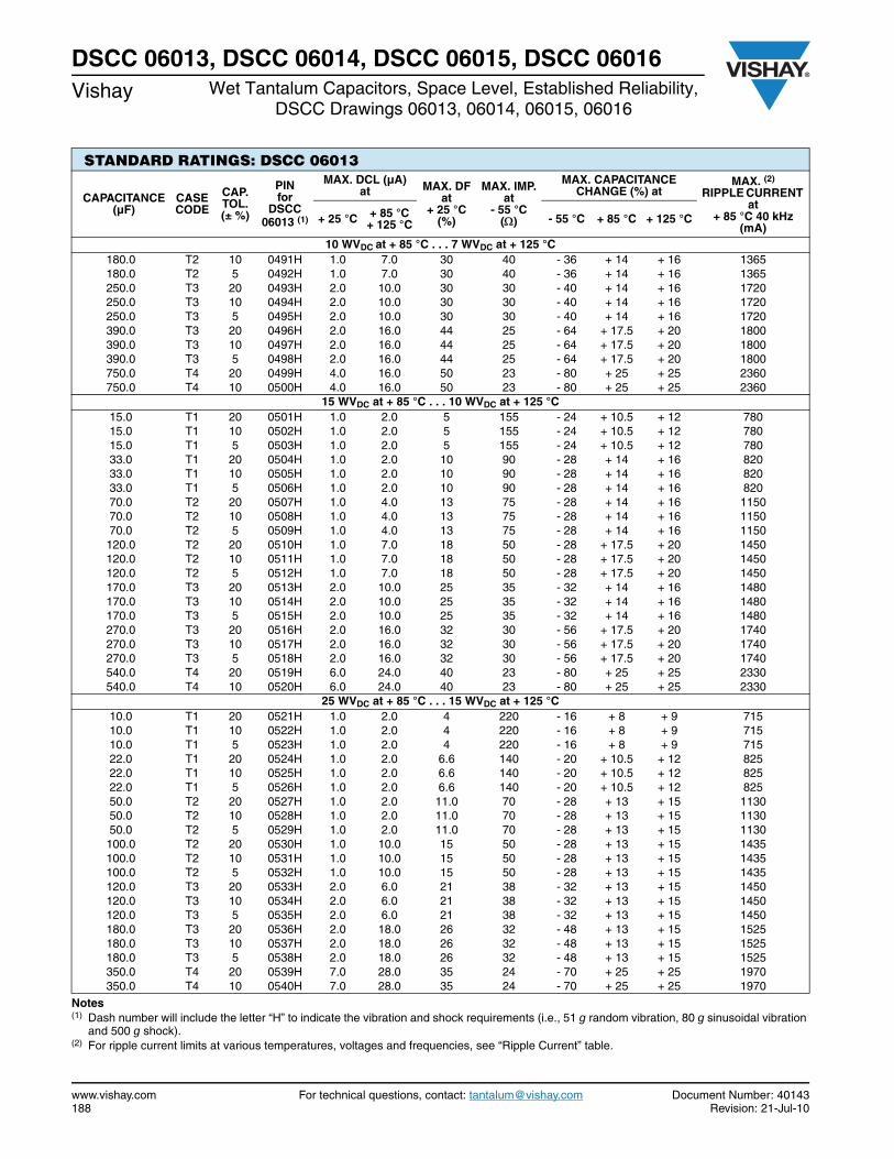
www.vishay.com For technical questions, contact: [email protected] Document Number: 40143188 Revision: 21-Jul-10
DSCC 06013, DSCC 06014, DSCC 06015, DSCC 06016Vishay Wet Tantalum Capacitors, Space Level, Established Reliability,
DSCC Drawings 06013, 06014, 06015, 06016
Notes(1) Dash number will include the letter “H” to indicate the vibration and shock requirements (i.e., 51 g random vibration, 80 g sinusoidal vibration
and 500 g shock).(2) For ripple current limits at various temperatures, voltages and frequencies, see “Ripple Current” table.
STANDARD RATINGS: DSCC 06013
CAPACITANCE (µF)
CASE CODE
CAP. TOL. (± %)
PINfor
DSCC 06013 (1)
MAX. DCL (µA)at MAX. DF
at + 25 °C
(%)
MAX. IMP.at
- 55 °C()
MAX. CAPACITANCE CHANGE (%) at
MAX. (2)
RIPPLE CURRENT at
+ 85 °C 40 kHz(mA)
+ 25 °C + 85 °C+ 125 °C - 55 °C + 85 °C + 125 °C
10 WVDC at + 85 °C . . . 7 WVDC at + 125 °C 180.0 T2 10 0491H 1.0 7.0 30 40 - 36 + 14 + 16 1365 180.0 T2 5 0492H 1.0 7.0 30 40 - 36 + 14 + 16 1365 250.0 T3 20 0493H 2.0 10.0 30 30 - 40 + 14 + 16 1720 250.0 T3 10 0494H 2.0 10.0 30 30 - 40 + 14 + 16 1720 250.0 T3 5 0495H 2.0 10.0 30 30 - 40 + 14 + 16 1720 390.0 T3 20 0496H 2.0 16.0 44 25 - 64 + 17.5 + 20 1800 390.0 T3 10 0497H 2.0 16.0 44 25 - 64 + 17.5 + 20 1800 390.0 T3 5 0498H 2.0 16.0 44 25 - 64 + 17.5 + 20 1800 750.0 T4 20 0499H 4.0 16.0 50 23 - 80 + 25 + 25 2360 750.0 T4 10 0500H 4.0 16.0 50 23 - 80 + 25 + 25 2360
15 WVDC at + 85 °C . . . 10 WVDC at + 125 °C 15.0 T1 20 0501H 1.0 2.0 5 155 - 24 + 10.5 + 12 780 15.0 T1 10 0502H 1.0 2.0 5 155 - 24 + 10.5 + 12 780 15.0 T1 5 0503H 1.0 2.0 5 155 - 24 + 10.5 + 12 780 33.0 T1 20 0504H 1.0 2.0 10 90 - 28 + 14 + 16 820 33.0 T1 10 0505H 1.0 2.0 10 90 - 28 + 14 + 16 820 33.0 T1 5 0506H 1.0 2.0 10 90 - 28 + 14 + 16 820 70.0 T2 20 0507H 1.0 4.0 13 75 - 28 + 14 + 16 1150 70.0 T2 10 0508H 1.0 4.0 13 75 - 28 + 14 + 16 1150 70.0 T2 5 0509H 1.0 4.0 13 75 - 28 + 14 + 16 1150 120.0 T2 20 0510H 1.0 7.0 18 50 - 28 + 17.5 + 20 1450 120.0 T2 10 0511H 1.0 7.0 18 50 - 28 + 17.5 + 20 1450 120.0 T2 5 0512H 1.0 7.0 18 50 - 28 + 17.5 + 20 1450 170.0 T3 20 0513H 2.0 10.0 25 35 - 32 + 14 + 16 1480 170.0 T3 10 0514H 2.0 10.0 25 35 - 32 + 14 + 16 1480 170.0 T3 5 0515H 2.0 10.0 25 35 - 32 + 14 + 16 1480 270.0 T3 20 0516H 2.0 16.0 32 30 - 56 + 17.5 + 20 1740 270.0 T3 10 0517H 2.0 16.0 32 30 - 56 + 17.5 + 20 1740 270.0 T3 5 0518H 2.0 16.0 32 30 - 56 + 17.5 + 20 1740 540.0 T4 20 0519H 6.0 24.0 40 23 - 80 + 25 + 25 2330 540.0 T4 10 0520H 6.0 24.0 40 23 - 80 + 25 + 25 2330
25 WVDC at + 85 °C . . . 15 WVDC at + 125 °C 10.0 T1 20 0521H 1.0 2.0 4 220 - 16 + 8 + 9 715 10.0 T1 10 0522H 1.0 2.0 4 220 - 16 + 8 + 9 715 10.0 T1 5 0523H 1.0 2.0 4 220 - 16 + 8 + 9 715 22.0 T1 20 0524H 1.0 2.0 6.6 140 - 20 + 10.5 + 12 825 22.0 T1 10 0525H 1.0 2.0 6.6 140 - 20 + 10.5 + 12 825 22.0 T1 5 0526H 1.0 2.0 6.6 140 - 20 + 10.5 + 12 825 50.0 T2 20 0527H 1.0 2.0 11.0 70 - 28 + 13 + 15 1130 50.0 T2 10 0528H 1.0 2.0 11.0 70 - 28 + 13 + 15 1130 50.0 T2 5 0529H 1.0 2.0 11.0 70 - 28 + 13 + 15 1130 100.0 T2 20 0530H 1.0 10.0 15 50 - 28 + 13 + 15 1435 100.0 T2 10 0531H 1.0 10.0 15 50 - 28 + 13 + 15 1435 100.0 T2 5 0532H 1.0 10.0 15 50 - 28 + 13 + 15 1435 120.0 T3 20 0533H 2.0 6.0 21 38 - 32 + 13 + 15 1450 120.0 T3 10 0534H 2.0 6.0 21 38 - 32 + 13 + 15 1450 120.0 T3 5 0535H 2.0 6.0 21 38 - 32 + 13 + 15 1450 180.0 T3 20 0536H 2.0 18.0 26 32 - 48 + 13 + 15 1525 180.0 T3 10 0537H 2.0 18.0 26 32 - 48 + 13 + 15 1525 180.0 T3 5 0538H 2.0 18.0 26 32 - 48 + 13 + 15 1525 350.0 T4 20 0539H 7.0 28.0 35 24 - 70 + 25 + 25 1970 350.0 T4 10 0540H 7.0 28.0 35 24 - 70 + 25 + 25 1970

Document Number: 40143 For technical questions, contact: [email protected] www.vishay.comRevision: 21-Jul-10 189
DSCC 06013, DSCC 06014, DSCC 06015, DSCC 06016Wet Tantalum Capacitors, Space Level, Established Reliability,
DSCC Drawings 06013, 06014, 06015, 06016Vishay
Notes(1) Dash number will include the letter “H” to indicate the vibration and shock requirements (i.e., 51 g random vibration, 80 g sinusoidal vibration
and 500 g shock).(2) For ripple current limits at various temperatures, voltages and frequencies, see “Ripple Current” table.
STANDARD RATINGS: DSCC 06013
CAPACITANCE (µF)
CASE CODE
CAP. TOL. (± %)
PIN for
DSCC 06013 (1)
MAX. DCL (µA)at MAX. DF
at + 25 °C
(%)
MAX. IMP.at
- 55 °C()
MAX. CAPACITANCE CHANGE (%) at
MAX. (2)
RIPPLE CURRENTat
+ 85 °C 40 kHz(mA)
+ 25 °C + 85 °C+ 125 °C - 55 °C + 85 °C + 125 °C
30 WVDC at + 85 °C . . . 20 WVDC at + 125 °C 8.0 T1 20 0541H 1.0 2.0 4 275 - 16 + 8 + 12 640 8.0 T1 10 0542H 1.0 2.0 4 275 - 16 + 8 + 12 640 8.0 T1 5 0543H 1.0 2.0 4 275 - 16 + 8 + 12 640 15.0 T1 20 0544H 1.0 2.0 5 175 - 20 + 10.5 + 12 780 15.0 T1 10 0545H 1.0 2.0 5 175 - 20 + 10.5 + 12 780 15.0 T1 5 0546H 1.0 2.0 5 175 - 20 + 10.5 + 12 780 40.0 T2 20 0547H 1.0 5.0 10 65 - 24 + 10.5 + 12 1120 40.0 T2 10 0548H 1.0 5.0 10 65 - 24 + 10.5 + 12 1120 40.0 T2 5 0549H 1.0 5.0 10 65 - 24 + 10.5 + 12 1120 68.0 T2 20 0550H 1.0 8.0 13 60 - 24 + 13 + 15 1285 68.0 T2 10 0551H 1.0 8.0 13 60 - 24 + 13 + 15 1285 68.0 T2 5 0552H 1.0 8.0 13 60 - 24 + 13 + 15 1285 100.0 T3 20 0553H 2.0 12.0 17 40 - 28 + 10.5 + 12 1450 100.0 T3 10 0554H 2.0 12.0 17 40 - 28 + 10.5 + 12 1450 100.0 T3 5 0555H 2.0 12.0 17 40 - 28 + 10.5 + 12 1450 150.0 T3 20 0556H 2.0 18.0 23 35 - 48 + 13 + 15 1525 150.0 T3 10 0557H 2.0 18.0 23 35 - 48 + 13 + 15 1525 150.0 T3 5 0558H 2.0 18.0 23 35 - 48 + 13 + 15 1525 300.0 T4 20 0559H 8.0 32.0 31 25 - 60 + 25 + 25 1950 300.0 T4 10 0560H 8.0 32.0 31 25 - 60 + 25 + 25 1950
50 WVDC at + 85 °C . . . 30 WVDC at + 125 °C 5.0 T1 20 0561H 1.0 2.0 3 400 - 16 + 5 + 6 580 5.0 T1 10 0562H 1.0 2.0 3 400 - 16 + 5 + 6 580 5.0 T1 5 0563H 1.0 2.0 3 400 - 16 + 5 + 6 580 10.0 T1 20 0564H 1.0 2.0 4 250 - 24 + 8 + 9 715 10.0 T1 10 0565H 1.0 2.0 4 250 - 24 + 8 + 9 715 10.0 T1 5 0566H 1.0 2.0 4 250 - 24 + 8 + 9 715 25.0 T2 20 0567H 1.0 5.0 8 95 - 20 + 10.5 + 12 1005 25.0 T2 10 0568H 1.0 5.0 8 95 - 20 + 10.5 + 12 1005 25.0 T2 5 0569H 1.0 5.0 8 95 - 20 + 10.5 + 12 1005 47.0 T2 20 0570H 1.0 9.0 11 70 - 28 + 13 + 15 1155 47.0 T2 10 0571H 1.0 9.0 11 70 - 28 + 13 + 15 1155 47.0 T2 5 0572H 1.0 9.0 11 70 - 28 + 13 + 15 1155 60.0 T3 20 0573H 2.0 12.0 12 45 - 16 + 10.5 + 12 1335 60.0 T3 10 0574H 2.0 12.0 12 45 - 16 + 10.5 + 12 1335 60.0 T3 5 0575H 2.0 12.0 12 45 - 16 + 10.5 + 12 1335 82.0 T3 20 0576H 2.0 16.0 15 45 - 32 + 13 + 15 1400 82.0 T3 10 0577H 2.0 16.0 15 45 - 32 + 13 + 15 1400 82.0 T3 5 0578H 2.0 16.0 15 45 - 32 + 13 + 15 1400 160.0 T4 20 0579H 8.0 32.0 17 27 - 50 + 25 + 25 1900 160.0 T4 10 0580H 8.0 32.0 17 27 - 50 + 25 + 25 1900
60 WVDC at + 85 °C . . . 40 WVDC at + 125 °C 4.0 T1 20 0581H 1.0 2.0 2.8 550 - 16 + 5 + 6 525 4.0 T1 10 0582H 1.0 2.0 2.8 550 - 16 + 5 + 6 525 4.0 T1 5 0583H 1.0 2.0 2.8 550 - 16 + 5 + 6 525 8.2 T1 20 0584H 1.0 2.0 4 275 - 24 + 8 + 9 625 8.2 T1 10 0585H 1.0 2.0 4 275 - 24 + 8 + 9 625 8.2 T1 5 0586H 1.0 2.0 4 275 - 24 + 8 + 9 625 20.0 T2 20 0587H 1.0 5.0 7 105 - 16 + 10.5 + 12 930 20.0 T2 10 0588H 1.0 5.0 7 105 - 16 + 10.5 + 12 930 20.0 T2 5 0589H 1.0 5.0 7 105 - 16 + 10.5 + 12 930 39.0 T2 20 0590H 1.0 9.0 10 90 - 28 + 10.5 + 12 1110
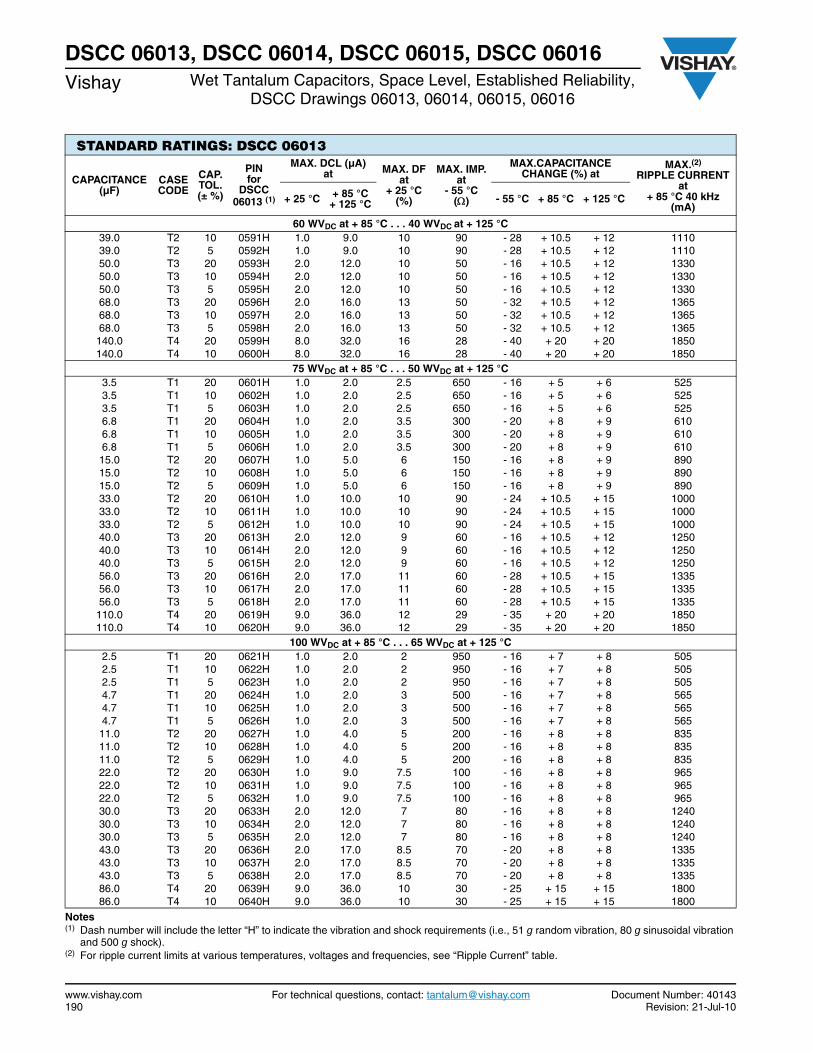
www.vishay.com For technical questions, contact: [email protected] Document Number: 40143190 Revision: 21-Jul-10
DSCC 06013, DSCC 06014, DSCC 06015, DSCC 06016Vishay Wet Tantalum Capacitors, Space Level, Established Reliability,
DSCC Drawings 06013, 06014, 06015, 06016
Notes(1) Dash number will include the letter “H” to indicate the vibration and shock requirements (i.e., 51 g random vibration, 80 g sinusoidal vibration
and 500 g shock).(2) For ripple current limits at various temperatures, voltages and frequencies, see “Ripple Current” table.
STANDARD RATINGS: DSCC 06013
CAPACITANCE (µF)
CASE CODE
CAP. TOL. (± %)
PIN for
DSCC 06013 (1)
MAX. DCL (µA)at MAX. DF
at + 25 °C
(%)
MAX. IMP.at
- 55 °C()
MAX.CAPACITANCE CHANGE (%) at
MAX.(2)
RIPPLE CURRENT at
+ 85 °C 40 kHz (mA)
+ 25 °C + 85 °C+ 125 °C - 55 °C + 85 °C + 125 °C
60 WVDC at + 85 °C . . . 40 WVDC at + 125 °C 39.0 T2 10 0591H 1.0 9.0 10 90 - 28 + 10.5 + 12 1110 39.0 T2 5 0592H 1.0 9.0 10 90 - 28 + 10.5 + 12 1110 50.0 T3 20 0593H 2.0 12.0 10 50 - 16 + 10.5 + 12 1330 50.0 T3 10 0594H 2.0 12.0 10 50 - 16 + 10.5 + 12 1330 50.0 T3 5 0595H 2.0 12.0 10 50 - 16 + 10.5 + 12 1330 68.0 T3 20 0596H 2.0 16.0 13 50 - 32 + 10.5 + 12 1365 68.0 T3 10 0597H 2.0 16.0 13 50 - 32 + 10.5 + 12 1365 68.0 T3 5 0598H 2.0 16.0 13 50 - 32 + 10.5 + 12 1365 140.0 T4 20 0599H 8.0 32.0 16 28 - 40 + 20 + 20 1850 140.0 T4 10 0600H 8.0 32.0 16 28 - 40 + 20 + 20 1850
75 WVDC at + 85 °C . . . 50 WVDC at + 125 °C 3.5 T1 20 0601H 1.0 2.0 2.5 650 - 16 + 5 + 6 525 3.5 T1 10 0602H 1.0 2.0 2.5 650 - 16 + 5 + 6 525 3.5 T1 5 0603H 1.0 2.0 2.5 650 - 16 + 5 + 6 525 6.8 T1 20 0604H 1.0 2.0 3.5 300 - 20 + 8 + 9 610 6.8 T1 10 0605H 1.0 2.0 3.5 300 - 20 + 8 + 9 610 6.8 T1 5 0606H 1.0 2.0 3.5 300 - 20 + 8 + 9 610 15.0 T2 20 0607H 1.0 5.0 6 150 - 16 + 8 + 9 890 15.0 T2 10 0608H 1.0 5.0 6 150 - 16 + 8 + 9 890 15.0 T2 5 0609H 1.0 5.0 6 150 - 16 + 8 + 9 890 33.0 T2 20 0610H 1.0 10.0 10 90 - 24 + 10.5 + 15 1000 33.0 T2 10 0611H 1.0 10.0 10 90 - 24 + 10.5 + 15 1000 33.0 T2 5 0612H 1.0 10.0 10 90 - 24 + 10.5 + 15 1000 40.0 T3 20 0613H 2.0 12.0 9 60 - 16 + 10.5 + 12 1250 40.0 T3 10 0614H 2.0 12.0 9 60 - 16 + 10.5 + 12 1250 40.0 T3 5 0615H 2.0 12.0 9 60 - 16 + 10.5 + 12 1250 56.0 T3 20 0616H 2.0 17.0 11 60 - 28 + 10.5 + 15 1335 56.0 T3 10 0617H 2.0 17.0 11 60 - 28 + 10.5 + 15 1335 56.0 T3 5 0618H 2.0 17.0 11 60 - 28 + 10.5 + 15 1335 110.0 T4 20 0619H 9.0 36.0 12 29 - 35 + 20 + 20 1850 110.0 T4 10 0620H 9.0 36.0 12 29 - 35 + 20 + 20 1850
100 WVDC at + 85 °C . . . 65 WVDC at + 125 °C 2.5 T1 20 0621H 1.0 2.0 2 950 - 16 + 7 + 8 505 2.5 T1 10 0622H 1.0 2.0 2 950 - 16 + 7 + 8 505 2.5 T1 5 0623H 1.0 2.0 2 950 - 16 + 7 + 8 505 4.7 T1 20 0624H 1.0 2.0 3 500 - 16 + 7 + 8 565 4.7 T1 10 0625H 1.0 2.0 3 500 - 16 + 7 + 8 565 4.7 T1 5 0626H 1.0 2.0 3 500 - 16 + 7 + 8 565 11.0 T2 20 0627H 1.0 4.0 5 200 - 16 + 8 + 8 835 11.0 T2 10 0628H 1.0 4.0 5 200 - 16 + 8 + 8 835 11.0 T2 5 0629H 1.0 4.0 5 200 - 16 + 8 + 8 835 22.0 T2 20 0630H 1.0 9.0 7.5 100 - 16 + 8 + 8 965 22.0 T2 10 0631H 1.0 9.0 7.5 100 - 16 + 8 + 8 965 22.0 T2 5 0632H 1.0 9.0 7.5 100 - 16 + 8 + 8 965 30.0 T3 20 0633H 2.0 12.0 7 80 - 16 + 8 + 8 1240 30.0 T3 10 0634H 2.0 12.0 7 80 - 16 + 8 + 8 1240 30.0 T3 5 0635H 2.0 12.0 7 80 - 16 + 8 + 8 1240 43.0 T3 20 0636H 2.0 17.0 8.5 70 - 20 + 8 + 8 1335 43.0 T3 10 0637H 2.0 17.0 8.5 70 - 20 + 8 + 8 1335 43.0 T3 5 0638H 2.0 17.0 8.5 70 - 20 + 8 + 8 1335 86.0 T4 20 0639H 9.0 36.0 10 30 - 25 + 15 + 15 1800 86.0 T4 10 0640H 9.0 36.0 10 30 - 25 + 15 + 15 1800
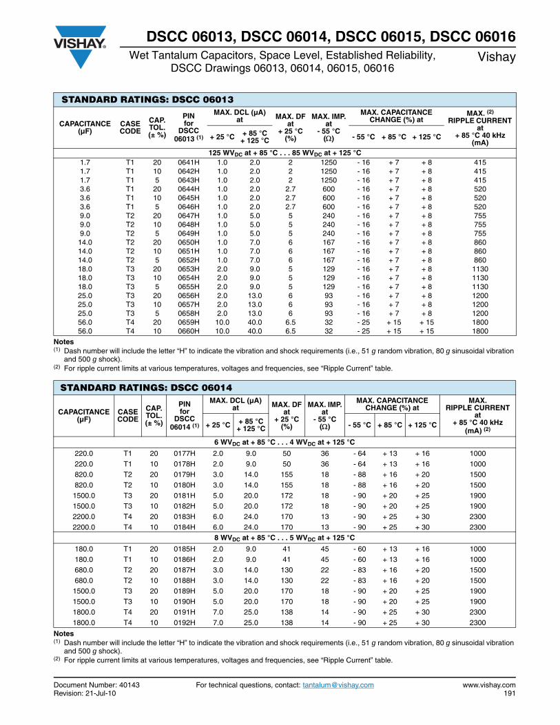
Document Number: 40143 For technical questions, contact: [email protected] www.vishay.comRevision: 21-Jul-10 191
DSCC 06013, DSCC 06014, DSCC 06015, DSCC 06016Wet Tantalum Capacitors, Space Level, Established Reliability,
DSCC Drawings 06013, 06014, 06015, 06016Vishay
Notes(1) Dash number will include the letter “H” to indicate the vibration and shock requirements (i.e., 51 g random vibration, 80 g sinusoidal vibration
and 500 g shock).(2) For ripple current limits at various temperatures, voltages and frequencies, see “Ripple Current” table.
Notes(1) Dash number will include the letter “H” to indicate the vibration and shock requirements (i.e., 51 g random vibration, 80 g sinusoidal vibration
and 500 g shock).(2) For ripple current limits at various temperatures, voltages and frequencies, see “Ripple Current” table.
STANDARD RATINGS: DSCC 06013
CAPACITANCE (µF)
CASE CODE
CAP. TOL. (± %)
PINfor
DSCC 06013 (1)
MAX. DCL (µA)at MAX. DF
at + 25 °C
(%)
MAX. IMP.at
- 55 °C()
MAX. CAPACITANCE CHANGE (%) at
MAX. (2)
RIPPLE CURRENT at
+ 85 °C 40 kHz (mA)
+ 25 °C + 85 °C+ 125 °C - 55 °C + 85 °C + 125 °C
125 WVDC at + 85 °C . . . 85 WVDC at + 125 °C 1.7 T1 20 0641H 1.0 2.0 2 1250 - 16 + 7 + 8 415 1.7 T1 10 0642H 1.0 2.0 2 1250 - 16 + 7 + 8 415 1.7 T1 5 0643H 1.0 2.0 2 1250 - 16 + 7 + 8 415 3.6 T1 20 0644H 1.0 2.0 2.7 600 - 16 + 7 + 8 520 3.6 T1 10 0645H 1.0 2.0 2.7 600 - 16 + 7 + 8 520 3.6 T1 5 0646H 1.0 2.0 2.7 600 - 16 + 7 + 8 520 9.0 T2 20 0647H 1.0 5.0 5 240 - 16 + 7 + 8 755 9.0 T2 10 0648H 1.0 5.0 5 240 - 16 + 7 + 8 755 9.0 T2 5 0649H 1.0 5.0 5 240 - 16 + 7 + 8 755 14.0 T2 20 0650H 1.0 7.0 6 167 - 16 + 7 + 8 860 14.0 T2 10 0651H 1.0 7.0 6 167 - 16 + 7 + 8 860 14.0 T2 5 0652H 1.0 7.0 6 167 - 16 + 7 + 8 860 18.0 T3 20 0653H 2.0 9.0 5 129 - 16 + 7 + 8 1130 18.0 T3 10 0654H 2.0 9.0 5 129 - 16 + 7 + 8 1130 18.0 T3 5 0655H 2.0 9.0 5 129 - 16 + 7 + 8 1130 25.0 T3 20 0656H 2.0 13.0 6 93 - 16 + 7 + 8 1200 25.0 T3 10 0657H 2.0 13.0 6 93 - 16 + 7 + 8 1200 25.0 T3 5 0658H 2.0 13.0 6 93 - 16 + 7 + 8 1200 56.0 T4 20 0659H 10.0 40.0 6.5 32 - 25 + 15 + 15 1800 56.0 T4 10 0660H 10.0 40.0 6.5 32 - 25 + 15 + 15 1800
STANDARD RATINGS: DSCC 06014
CAPACITANCE (µF)
CASE CODE
CAP. TOL. (± %)
PINfor
DSCC 06014 (1)
MAX. DCL (µA)at MAX. DF
at + 25 °C
(%)
MAX. IMP.at
- 55 °C()
MAX. CAPACITANCE CHANGE (%) at
MAX. RIPPLE CURRENT
at + 85 °C 40 kHz
(mA) (2)+ 25 °C + 85 °C
+ 125 °C - 55 °C + 85 °C + 125 °C
6 WVDC at + 85 °C . . . 4 WVDC at + 125 °C
220.0 T1 20 0177H 2.0 9.0 50 36 - 64 + 13 + 16 1000 220.0 T1 10 0178H 2.0 9.0 50 36 - 64 + 13 + 16 1000 820.0 T2 20 0179H 3.0 14.0 155 18 - 88 + 16 + 20 1500 820.0 T2 10 0180H 3.0 14.0 155 18 - 88 + 16 + 20 1500
1500.0 T3 20 0181H 5.0 20.0 172 18 - 90 + 20 + 25 1900 1500.0 T3 10 0182H 5.0 20.0 172 18 - 90 + 20 + 25 1900 2200.0 T4 20 0183H 6.0 24.0 170 13 - 90 + 25 + 30 2300 2200.0 T4 10 0184H 6.0 24.0 170 13 - 90 + 25 + 30 2300
8 WVDC at + 85 °C . . . 5 WVDC at + 125 °C
180.0 T1 20 0185H 2.0 9.0 41 45 - 60 + 13 + 16 1000 180.0 T1 10 0186H 2.0 9.0 41 45 - 60 + 13 + 16 1000 680.0 T2 20 0187H 3.0 14.0 130 22 - 83 + 16 + 20 1500 680.0 T2 10 0188H 3.0 14.0 130 22 - 83 + 16 + 20 1500
1500.0 T3 20 0189H 5.0 20.0 170 18 - 90 + 20 + 25 1900 1500.0 T3 10 0190H 5.0 20.0 170 18 - 90 + 20 + 25 1900 1800.0 T4 20 0191H 7.0 25.0 138 14 - 90 + 25 + 30 2300 1800.0 T4 10 0192H 7.0 25.0 138 14 - 90 + 25 + 30 2300

www.vishay.com For technical questions, contact: [email protected] Document Number: 40143192 Revision: 21-Jul-10
DSCC 06013, DSCC 06014, DSCC 06015, DSCC 06016Vishay Wet Tantalum Capacitors, Space Level, Established Reliability,
DSCC Drawings 06013, 06014, 06015, 06016
Notes(1) Dash number will include the letter “H” to indicate the vibration and shock requirements (i.e., 51 g random vibration, 80 g sinusoidal vibration
and 500 g shock).(2) For ripple current limits at various temperatures, voltages and frequencies, see “Ripple Current” table.
STANDARD RATINGS: DSCC 06014
CAPACITANCE (µF)
CASE CODE
CAP. TOL. (± %)
PIN for
DSCC 06014 (1)
MAX. DCL (µA)at MAX. DF
at + 25 °C
(%)
MAX. IMP.at
- 55 °C()
MAX. CAPACITANCE CHANGE (%) at
MAX. (2)
RIPPLE CURRENTat
+ 85 °C 40 kHz(mA)
+ 25 °C + 85 °C+ 125 °C - 55 °C + 85 °C + 125 °C
10 WVDC at + 85 °C . . . 7 WVDC at + 125 °C 150.0 T1 20 0193H 2.0 9.0 34 54 - 55 + 13 + 16 900 150.0 T1 10 0194H 2.0 9.0 34 54 - 55 + 13 + 16 900 560.0 T2 20 0195H 3.0 16.0 106 27 - 77 + 16 + 20 1450 560.0 T2 10 0196H 3.0 16.0 106 27 - 77 + 16 + 20 1450 1200.0 T3 20 0197H 5.0 20.0 137 18 - 88 + 20 + 25 1850 1200.0 T3 10 0198H 5.0 20.0 137 18 - 88 + 20 + 25 1850 1500.0 T4 20 0199H 7.0 25.0 114 15 - 88 + 25 + 30 2300 1500.0 T4 10 0200H 7.0 25.0 114 15 - 88 + 25 + 30 2300
15 WVDC at + 85 °C . . . 10 WVDC at + 125 °C 100.0 T1 20 0201H 2.0 9.0 30 72 - 44 + 13 + 16 900 100.0 T1 10 0202H 2.0 9.0 30 72 - 44 + 13 + 16 900 390.0 T2 20 0203H 3.0 16.0 74 31 - 66 + 16 + 20 1450 390.0 T2 10 0204H 3.0 16.0 74 31 - 66 + 16 + 20 1450 820.0 T3 20 0205H 6.0 24.0 111 22 - 77 + 20 + 25 1800 820.0 T3 10 0206H 6.0 24.0 111 22 - 77 + 20 + 25 180 0 1000.0 T4 20 0207H 8.0 32.0 92 17 - 77 + 25 + 30 2300 1000.0 T4 10 0208H 8.0 32.0 92 17 - 77 + 25 + 30 2300
25 WVDC at + 85 °C . . . 15 WVDC at + 125 °C 68.0 T1 20 0209H 2.0 9.0 22 90 - 40 + 12 + 15 850 68.0 T1 10 0210H 2.0 9.0 22 90 - 40 + 12 + 15 850 270.0 T2 20 0211H 3.0 16.0 55 33 - 62 + 13 + 16 1400 270.0 T2 10 0212H 3.0 16.0 55 33 - 62 + 13 + 16 1400 560.0 T3 20 0213H 7.0 28.0 76 24 - 72 + 20 + 25 1750 560.0 T3 10 0214H 7.0 28.0 76 24 - 72 + 20 + 25 1750 680.0 T4 20 0215H 8.0 32.0 63 19 - 72 + 25 + 30 2100 680.0 T4 10 0216H 8.0 32.0 63 19 - 72 + 25 + 30 2100
30 WVDC at + 85 °C . . . 20 WVDC at + 125 °C 56.0 T1 20 0217H 2.0 9.0 22 100 - 38 + 12 + 15 800 56.0 T1 10 0218H 2.0 9.0 22 100 - 38 + 12 + 15 800 220.0 T2 20 0219H 3.0 16.0 42 36 - 60 + 13 + 16 1200 220.0 T2 10 0220H 3.0 16.0 42 36 - 60 + 13 + 16 1200 470.0 T3 20 0221H 8.0 32.0 64 25 - 65 + 20 + 25 1500 470.0 T3 10 0222H 8.0 32.0 64 25 - 65 + 20 + 25 1500 560.0 T4 20 0223H 9.0 36.0 55 20 - 65 + 25 + 30 2000 560.0 T4 10 0224H 9.0 36.0 55 20 - 65 + 25 + 30 2000
50 WVDC at + 85 °C . . . 30 WVDC at + 125 °C 33.0 T1 20 0225H 2.0 9.0 12.3 135 - 29 + 10 + 12 700 33.0 T1 10 0226H 2.0 9.0 12.3 135 - 29 + 10 + 12 700 120.0 T2 20 0227H 4.0 24.0 22.5 49 - 42 + 12 + 15 1200 120.0 T2 10 0228H 4.0 24.0 22.5 49 - 42 + 12 + 15 1200 270.0 T3 20 0229H 8.0 32.0 37 29 - 46 + 20 + 25 1450 270.0 T3 10 0230H 8.0 32.0 37 29 - 46 + 20 + 25 1450 330.0 T4 20 0231H 9.0 36.0 38 22 - 46 + 25 + 30 1900 330.0 T4 10 0232H 9.0 36.0 38 22 - 46 + 25 + 30 1900
60 WVDC at + 85 °C . . . 40 WVDC at + 125 °C 27.0 T1 20 0233H 3.0 12.0 10.2 144 - 24 + 10 + 12 700 27.0 T1 10 0234H 3.0 12.0 10.2 144 - 24 + 10 + 12 700 100.0 T2 20 0235H 4.0 20.0 19 54 - 36 + 12 + 15 1100 100.0 T2 10 0236H 4.0 20.0 19 54 - 36 + 12 + 15 1100 220.0 T3 20 0237H 8.0 32.0 30 29 - 40 + 16 + 20 1400 220.0 T3 10 0238H 8.0 32.0 30 29 - 40 + 16 + 20 1400 270.0 T4 20 0239H 9.0 36.0 27 23 - 45 + 20 + 25 1850 270.0 T4 10 0240H 9.0 36.0 27 23 - 45 + 20 + 25 1850
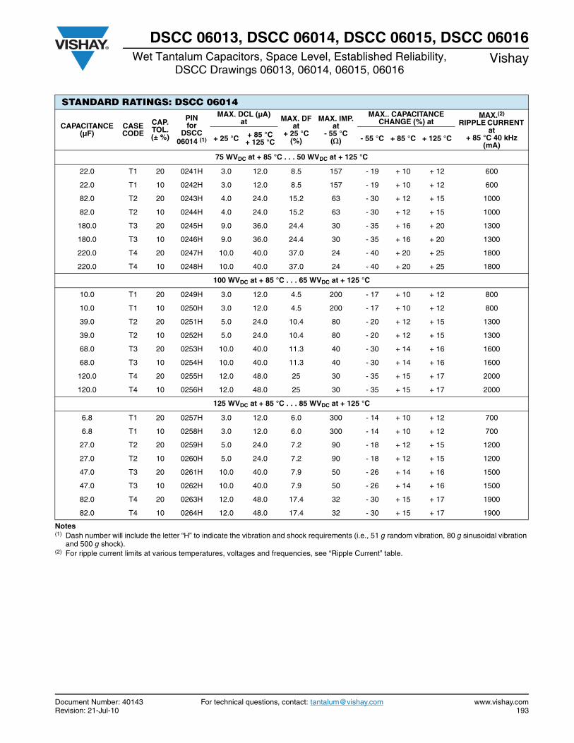
Document Number: 40143 For technical questions, contact: [email protected] www.vishay.comRevision: 21-Jul-10 193
DSCC 06013, DSCC 06014, DSCC 06015, DSCC 06016Wet Tantalum Capacitors, Space Level, Established Reliability,
DSCC Drawings 06013, 06014, 06015, 06016Vishay
Notes(1) Dash number will include the letter “H” to indicate the vibration and shock requirements (i.e., 51 g random vibration, 80 g sinusoidal vibration
and 500 g shock).(2) For ripple current limits at various temperatures, voltages and frequencies, see “Ripple Current” table.
STANDARD RATINGS: DSCC 06014
CAPACITANCE (µF)
CASE CODE
CAP. TOL. (± %)
PINfor
DSCC 06014 (1)
MAX. DCL (µA)at MAX. DF
at + 25 °C
(%)
MAX. IMP.at
- 55 °C()
MAX.. CAPACITANCE CHANGE (%) at
MAX.(2)
RIPPLE CURRENT at
+ 85 °C 40 kHz (mA)
+ 25 °C + 85 °C+ 125 °C - 55 °C + 85 °C + 125 °C
75 WVDC at + 85 °C . . . 50 WVDC at + 125 °C
22.0 T1 20 0241H 3.0 12.0 8.5 157 - 19 + 10 + 12 600
22.0 T1 10 0242H 3.0 12.0 8.5 157 - 19 + 10 + 12 600
82.0 T2 20 0243H 4.0 24.0 15.2 63 - 30 + 12 + 15 1000
82.0 T2 10 0244H 4.0 24.0 15.2 63 - 30 + 12 + 15 1000
180.0 T3 20 0245H 9.0 36.0 24.4 30 - 35 + 16 + 20 1300
180.0 T3 10 0246H 9.0 36.0 24.4 30 - 35 + 16 + 20 1300
220.0 T4 20 0247H 10.0 40.0 37.0 24 - 40 + 20 + 25 1800
220.0 T4 10 0248H 10.0 40.0 37.0 24 - 40 + 20 + 25 1800
100 WVDC at + 85 °C . . . 65 WVDC at + 125 °C
10.0 T1 20 0249H 3.0 12.0 4.5 200 - 17 + 10 + 12 800
10.0 T1 10 0250H 3.0 12.0 4.5 200 - 17 + 10 + 12 800
39.0 T2 20 0251H 5.0 24.0 10.4 80 - 20 + 12 + 15 1300
39.0 T2 10 0252H 5.0 24.0 10.4 80 - 20 + 12 + 15 1300
68.0 T3 20 0253H 10.0 40.0 11.3 40 - 30 + 14 + 16 1600
68.0 T3 10 0254H 10.0 40.0 11.3 40 - 30 + 14 + 16 1600
120.0 T4 20 0255H 12.0 48.0 25 30 - 35 + 15 + 17 2000
120.0 T4 10 0256H 12.0 48.0 25 30 - 35 + 15 + 17 2000
125 WVDC at + 85 °C . . . 85 WVDC at + 125 °C
6.8 T1 20 0257H 3.0 12.0 6.0 300 - 14 + 10 + 12 700
6.8 T1 10 0258H 3.0 12.0 6.0 300 - 14 + 10 + 12 700
27.0 T2 20 0259H 5.0 24.0 7.2 90 - 18 + 12 + 15 1200
27.0 T2 10 0260H 5.0 24.0 7.2 90 - 18 + 12 + 15 1200
47.0 T3 20 0261H 10.0 40.0 7.9 50 - 26 + 14 + 16 1500
47.0 T3 10 0262H 10.0 40.0 7.9 50 - 26 + 14 + 16 1500
82.0 T4 20 0263H 12.0 48.0 17.4 32 - 30 + 15 + 17 1900
82.0 T4 10 0264H 12.0 48.0 17.4 32 - 30 + 15 + 17 1900
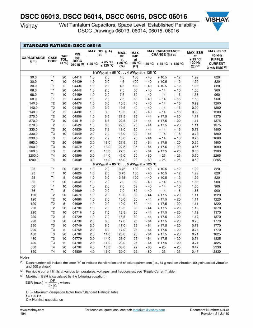
www.vishay.com For technical questions, contact: [email protected] Document Number: 40143194 Revision: 21-Jul-10
DSCC 06013, DSCC 06014, DSCC 06015, DSCC 06016Vishay Wet Tantalum Capacitors, Space Level, Established Reliability,
DSCC Drawings 06013, 06014, 06015, 06016
Notes(1) Dash number will include the letter “H” to indicate the vibration and shock requirements (i.e., 51 g random vibration, 80 g sinusoidal vibration
and 500 g shock).(2) For ripple current limits at various temperatures, voltages, and frequencies, see “Ripple Current” table.(3) Maximum ESR is calculated by the following equation:
DF = Maximum dissipation factor from “Standard Ratings” table f = 120 HzC = Nominal capacitance
STANDARD RATINGS: DSCC 06015
CAPACITANCE (µF)
CASE CODE
CAP. TOL. (± %)
PIN for
DSCC 06015 (1)
MAX. DCL (µA)at MAX.
DFat
+ 25 °C(%)
MAX. IMP.at
- 55 °C()
MAX. CAPACITANCE CHANGE (%) at MAX. ESR
at + 25 °C120 Hz() (2)
MAX. 85 °C40 kHzRIPPLE
CURRENT3 mA RMS (3)
+ 25 °C + 85 °C+ 125 °C - 55 °C + 85 °C + 125 °C
6 WVDC at + 85 °C . . . 4 WVDC at + 125 °C 30.0 T1 20 0441H 1.0 2.0 4.5 100 - 40 + 10.5 + 12 1.99 82030.0 T1 10 0442H 1.0 2.0 4.5 100 - 40 + 10.5 + 12 1.99 82030.0 T1 5 0443H 1.0 2.0 4.5 100 - 40 + 10.5 + 12 1.99 82068.0 T1 20 0444H 1.0 2.0 7.5 60 - 40 + 14 + 16 1.58 96068.0 T1 10 0445H 1.0 2.0 7.5 60 - 40 + 14 + 16 1.58 96068.0 T1 5 0446H 1.0 2.0 7.5 60 - 40 + 14 + 16 1.58 960140.0 T2 20 0447H 1.0 3.0 10.5 40 - 40 + 14 + 16 0.99 1200140.0 T2 10 0448H 1.0 3.0 10.5 40 - 40 + 14 + 16 0.99 1200140.0 T2 5 0449H 1.0 3.0 10.5 40 - 40 + 14 + 16 0.99 1200270.0 T2 20 0450H 1.0 6.5 22.5 25 - 44 + 17.5 + 20 1.11 1375270.0 T2 10 0451H 1.0 6.5 22.5 25 - 44 + 17.5 + 20 1.11 1375270.0 T2 5 0452H 1.0 6.5 22.5 25 - 44 + 17.5 + 20 1.11 1375330.0 T3 20 0453H 2.0 7.9 18.0 20 - 44 + 14 + 16 0.73 1800330.0 T3 10 0454H 2.0 7.9 18.0 20 - 44 + 14 + 16 0.73 1800330.0 T3 5 0455H 2.0 7.9 18.0 20 - 44 + 14 + 16 0.73 1800560.0 T3 20 0456H 2.0 13.0 27.5 25 - 64 + 17.5 + 20 0.65 1900560.0 T3 10 0457H 2.0 13.0 27.5 25 - 64 + 17.5 + 20 0.65 1900560.0 T3 5 0458H 2.0 13.0 27.5 25 - 64 + 17.5 + 20 0.65 19001200.0 T4 20 0459H 3.0 14.0 45.0 20 - 80 + 25 + 25 0.50 22651200.0 T4 10 0460H 3.0 14.0 45.0 20 - 80 + 25 + 25 0.50 2265
8 WVDC at + 85 °C . . . 5 WVDC at + 125 °C 25 T1 20 0461H 1.0 2.0 3.75 100 - 40 + 10.5 + 12 1.99 82025 T1 10 0462H 1.0 2.0 3.75 100 - 40 + 10.5 + 12 1.99 82025 T1 5 0463H 1.0 2.0 3.75 100 - 40 + 10.5 + 12 1.99 82056 T1 20 0464H 1.0 2.0 7.0 59 - 40 + 14 + 16 1.66 90056 T1 10 0465H 1.0 2.0 7.0 59 - 40 + 14 + 16 1.66 90056 T1 5 0466H 1.0 2.0 7.0 59 - 40 + 14 + 16 1.66 900120 T2 20 0467H 1.0 2.0 10.0 50 - 44 + 17.5 + 20 1.11 1220120 T2 10 0468H 1.0 2.0 10.0 50 - 44 + 17.5 + 20 1.11 1220120 T2 5 0469H 1.0 2.0 10.0 50 - 44 + 17.5 + 20 1.11 1220220 T2 20 0470H 1.0 7.0 18.5 30 - 44 + 17.5 + 20 1.12 1370220 T2 10 0471H 1.0 7.0 18.5 30 - 44 + 17.5 + 20 1.12 1370220 T2 5 0472H 1.0 7.0 18.5 30 - 44 + 17.5 + 20 1.12 1370290 T3 20 0473H 2.0 6.0 17.0 25 - 64 + 17.5 + 20 0.78 1770290 T3 10 0474H 2.0 6.0 17.0 25 - 64 + 17.5 + 20 0.78 1770290 T3 5 0475H 2.0 6.0 17.0 25 - 64 + 17.5 + 20 0.78 1770430 T3 20 0476H 2.0 14.0 23.0 25 - 64 + 17.5 + 20 0.71 1825430 T3 10 0477H 2.0 14.0 23.0 25 - 64 + 17.5 + 20 0.71 1825430 T3 5 0478H 2.0 14.0 23.0 25 - 64 + 17.5 + 20 0.71 1825850 T4 20 0479H 4.0 16.0 30.0 22 - 80 + 25 + 25 0.47 2330850 T4 10 0480H 4.0 16.0 30.0 22 - 80 + 25 + 25 0.47 2330
ESR (max.) DF
2 C-------------- where,=
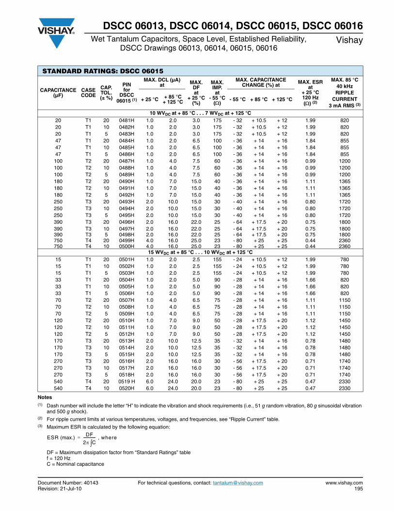
Document Number: 40143 For technical questions, contact: [email protected] www.vishay.comRevision: 21-Jul-10 195
DSCC 06013, DSCC 06014, DSCC 06015, DSCC 06016Wet Tantalum Capacitors, Space Level, Established Reliability,
DSCC Drawings 06013, 06014, 06015, 06016Vishay
Notes(1) Dash number will include the letter “H” to indicate the vibration and shock requirements (i.e., 51 g random vibration, 80 g sinusoidal vibration
and 500 g shock).(2) For ripple current limits at various temperatures, voltages, and frequencies, see “Ripple Current” table.(3) Maximum ESR is calculated by the following equation:
DF = Maximum dissipation factor from “Standard Ratings” table f = 120 HzC = Nominal capacitance
STANDARD RATINGS: DSCC 06015
CAPACITANCE (µF)
CASE CODE
CAP. TOL. (± %)
PIN for
DSCC 06015 (1)
MAX. DCL (µA)at MAX.
DFat
+ 25 °C(%)
MAX. IMP.at
- 55 °C()
MAX. CAPACITANCE CHANGE (%) at MAX. ESR
at + 25 °C120 Hz() (2)
MAX. 85 °C40 kHzRIPPLE
CURRENT3 mA RMS (3)
+ 25 °C + 85 °C+ 125 °C - 55 °C + 85 °C + 125 °C
10 WVDC at + 85 °C . . . 7 WVDC at + 125 °C 20 T1 20 0481H 1.0 2.0 3.0 175 - 32 + 10.5 + 12 1.99 82020 T1 10 0482H 1.0 2.0 3.0 175 - 32 + 10.5 + 12 1.99 82020 T1 5 0483H 1.0 2.0 3.0 175 - 32 + 10.5 + 12 1.99 82047 T1 20 0484H 1.0 2.0 6.5 100 - 36 + 14 + 16 1.84 85547 T1 10 0485H 1.0 2.0 6.5 100 - 36 + 14 + 16 1.84 85547 T1 5 0486H 1.0 2.0 6.5 100 - 36 + 14 + 16 1.84 855100 T2 20 0487H 1.0 4.0 7.5 60 - 36 + 14 + 16 0.99 1200100 T2 10 0488H 1.0 4.0 7.5 60 - 36 + 14 + 16 0.99 1200100 T2 5 0489H 1.0 4.0 7.5 60 - 36 + 14 + 16 0.99 1200180 T2 20 0490H 1.0 7.0 15.0 40 - 36 + 14 + 16 1.11 1365180 T2 10 0491H 1.0 7.0 15.0 40 - 36 + 14 + 16 1.11 1365180 T2 5 0492H 1.0 7.0 15.0 40 - 36 + 14 + 16 1.11 1365250 T3 20 0493H 2.0 10.0 15.0 30 - 40 + 14 + 16 0.80 1720250 T3 10 0494H 2.0 10.0 15.0 30 - 40 + 14 + 16 0.80 1720250 T3 5 0495H 2.0 10.0 15.0 30 - 40 + 14 + 16 0.80 1720390 T3 20 0496H 2.0 16.0 22.0 25 - 64 + 17.5 + 20 0.75 1800390 T3 10 0497H 2.0 16.0 22.0 25 - 64 + 17.5 + 20 0.75 1800390 T3 5 0498H 2.0 16.0 22.0 25 - 64 + 17.5 + 20 0.75 1800750 T4 20 0499H 4.0 16.0 25.0 23 - 80 + 25 + 25 0.44 2360750 T4 10 0500H 4.0 16.0 25.0 23 - 80 + 25 + 25 0.44 2360
15 WVDC at + 85 °C . . . 10 WVDC at + 125 °C 15 T1 20 0501H 1.0 2.0 2.5 155 - 24 + 10.5 + 12 1.99 78015 T1 10 0502H 1.0 2.0 2.5 155 - 24 + 10.5 + 12 1.99 78015 T1 5 0503H 1.0 2.0 2.5 155 - 24 + 10.5 + 12 1.99 78033 T1 20 0504H 1.0 2.0 5.0 90 - 28 + 14 + 16 1.66 82033 T1 10 0505H 1.0 2.0 5.0 90 - 28 + 14 + 16 1.66 82033 T1 5 0506H 1.0 2.0 5.0 90 - 28 + 14 + 16 1.66 82070 T2 20 0507H 1.0 4.0 6.5 75 - 28 + 14 + 16 1.11 115070 T2 10 0508H 1.0 4.0 6.5 75 - 28 + 14 + 16 1.11 115070 T2 5 0509H 1.0 4.0 6.5 75 - 28 + 14 + 16 1.11 1150120 T2 20 0510H 1.0 7.0 9.0 50 - 28 + 17.5 + 20 1.12 1450120 T2 10 0511H 1.0 7.0 9.0 50 - 28 + 17.5 + 20 1.12 1450120 T2 5 0512H 1.0 7.0 9.0 50 - 28 + 17.5 + 20 1.12 1450170 T3 20 0513H 2.0 10.0 12.5 35 - 32 + 14 + 16 0.78 1480170 T3 10 0514H 2.0 10.0 12.5 35 - 32 + 14 + 16 0.78 1480170 T3 5 0515H 2.0 10.0 12.5 35 - 32 + 14 + 16 0.78 1480270 T3 20 0516H 2.0 16.0 16.0 30 - 56 + 17.5 + 20 0.71 1740270 T3 10 0517H 2.0 16.0 16.0 30 - 56 + 17.5 + 20 0.71 1740270 T3 5 0518H 2.0 16.0 16.0 30 - 56 + 17.5 + 20 0.71 1740540 T4 20 0519 H 6.0 24.0 20.0 23 - 80 + 25 + 25 0.47 2330540 T4 10 0520H 6.0 24.0 20.0 23 - 80 + 25 + 25 0.47 2330
ESR (max.) DF
2 C-------------- where,=
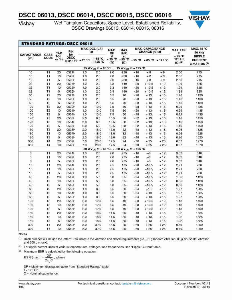
www.vishay.com For technical questions, contact: [email protected] Document Number: 40143196 Revision: 21-Jul-10
DSCC 06013, DSCC 06014, DSCC 06015, DSCC 06016Vishay Wet Tantalum Capacitors, Space Level, Established Reliability,
DSCC Drawings 06013, 06014, 06015, 06016
Notes(1) Dash number will include the letter “H” to indicate the vibration and shock requirements (i.e., 51 g random vibration, 80 g sinusoidal vibration
and 500 g shock).(2) For ripple current limits at various temperatures, voltages, and frequencies, see “Ripple Current” table.(3) Maximum ESR is calculated by the following equation:
DF = Maximum dissipation factor from “Standard Ratings” table f = 120 HzC = Nominal capacitance
STANDARD RATINGS: DSCC 06015
CAPACITANCE (µF)
CASE CODE
CAP. TOL. (± %)
PIN for
DSCC 06015 (1)
MAX. DCL (µA)at MAX.
DFat
+ 25 °C(%)
MAX. IMP.at
- 55 °C()
MAX. CAPACITANCE CHANGE (%) at MAX. ESR
at + 25 °C120 Hz() (2)
MAX. 85 °C40 kHzRIPPLE
CURRENT3 mA RMS (3)
+ 25 °C + 85 °C+ 125 °C - 55 °C + 85 °C + 125 °C
25 WVDC at + 85 °C . . . 15 WVDC at + 125 °C 10 T1 20 0521H 1.0 2.0 2.0 220 - 16 + 8 + 9 2.66 71510 T1 10 0522H 1.0 2.0 2.0 220 - 16 + 8 + 9 2.66 71510 T1 5 0523H 1.0 2.0 2.0 220 - 16 + 8 + 9 2.66 71522 T1 20 0524H 1.0 2.0 3.3 140 - 20 + 10.5 + 12 1.99 82522 T1 10 0525H 1.0 2.0 3.3 140 - 20 + 10.5 + 12 1.99 82522 T1 5 0526H 1.0 2.0 3.3 140 - 20 + 10.5 + 12 1.99 82550 T2 20 0527H 1.0 2.0 5.5 70 - 28 + 13 + 15 1.46 113050 T2 10 0528H 1.0 2.0 5.5 70 - 28 + 13 + 15 1.46 113050 T2 5 0529H 1.0 2.0 5.5 70 - 28 + 13 + 15 1.46 1130100 T2 20 0530H 1.0 10.0 7.5 50 - 28 + 13 + 15 0.99 1435100 T2 10 0531H 1.0 10.0 7.5 50 - 28 + 13 + 15 0.99 1435100 T2 5 0532H 1.0 10.0 7.5 50 - 28 + 13 + 15 0.99 1435120 T3 20 0533H 2.0 6.0 10.5 38 - 32 + 13 + 15 1.16 1450120 T3 10 0534H 2.0 6.0 10.5 38 - 32 + 13 + 15 1.16 1450120 T3 5 0535H 2.0 6.0 10.5 38 - 32 + 13 + 15 1.16 1450180 T3 20 0536H 2.0 18.0 13.0 32 - 48 + 13 + 15 0.96 1525180 T3 10 0537H 2.0 18.0 13.0 32 - 48 + 13 + 15 0.96 1525180 T3 5 0538H 2.0 18.0 13.0 32 - 48 + 13 + 15 0.96 1525350 T4 20 0539H 7.0 28.0 17.5 24 - 70 + 25 + 25 0.67 1970350 T4 10 0540H 7.0 28.0 17.5 24 - 70 + 25 + 25 0.67 1970
30 WVDC at + 85 °C . . . 20 WVDC at + 125 °C 8 T1 20 0541H 1.0 2.0 2.0 275 - 16 +8 + 12 3.32 6408 T1 10 0542H 1.0 2.0 2.0 275 - 16 +8 + 12 3.32 6408 T1 5 0543H 1.0 2.0 2.0 275 - 16 +8 + 12 3.32 640
15 T1 20 0544H 1.0 2.0 2.5 175 - 20 +10.5 + 12 2.21 78015 T1 10 0545H 1.0 2.0 2.5 175 - 20 +10.5 + 12 2.21 78015 T1 5 0546H 1.0 2.0 2.5 175 - 20 +10.5 + 12 2.21 78040 T2 20 0547H 1.0 5.0 5.0 65 - 24 +10.5 + 12 1.66 1120 40 T2 10 0548H 1.0 5.0 5.0 65 - 24 +10.5 + 12 0.66 1120 40 T2 5 0549H 1.0 5.0 5.0 65 - 24 +10.5 + 12 0.66 1120 68 T2 20 0550H 1.0 8.0 6.5 60 - 24 +13 + 15 1.27 128568 T2 10 0551H 1.0 8.0 6.5 60 - 24 + 13 + 15 1.27 128568 T2 5 0552H 1.0 8.0 6.5 60 - 24 + 13 + 15 1.27 1285100 T3 20 0553H 2.0 12.0 8.5 40 - 28 + 10.5 + 12 1.13 1450100 T3 10 0554H 2.0 12.0 8.5 40 - 28 + 10.5 + 12 1.13 1450100 T3 5 0555H 2.0 12.0 8.5 40 - 28 + 10.5 + 12 1.13 1450150 T3 20 0556H 2.0 18.0 11.5 35 - 48 + 13 + 15 1.02 1525150 T3 10 0557H 2.0 18.0 11.5 35 - 48 + 13 + 15 1.02 1525150 T3 5 0558H 2.0 18.0 11.5 35 - 48 + 13 + 15 1.02 1525300 T4 20 0559H 8.0 32.0 15.5 25 - 60 + 25 + 25 0.69 1950300 T4 10 0560H 8.0 32.0 15.5 25 - 60 + 25 + 25 0.69 1950
ESR (max.) DF
2 C-------------- where,=
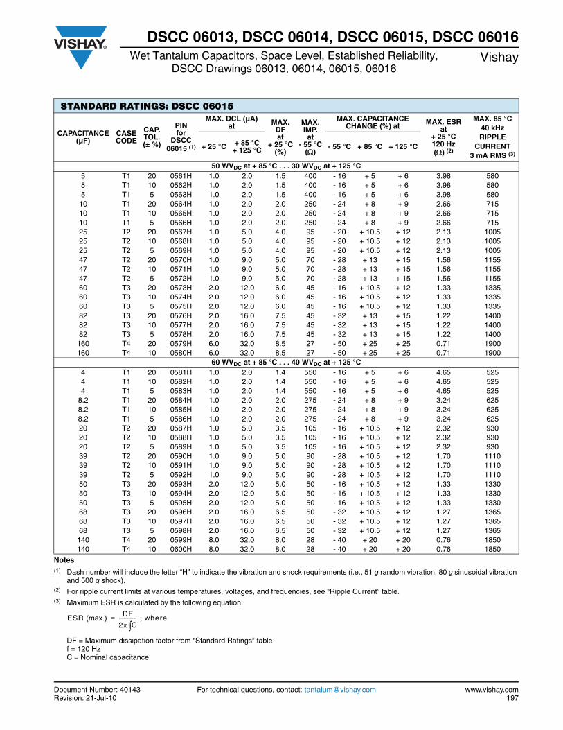
Document Number: 40143 For technical questions, contact: [email protected] www.vishay.comRevision: 21-Jul-10 197
DSCC 06013, DSCC 06014, DSCC 06015, DSCC 06016Wet Tantalum Capacitors, Space Level, Established Reliability,
DSCC Drawings 06013, 06014, 06015, 06016Vishay
Notes(1) Dash number will include the letter “H” to indicate the vibration and shock requirements (i.e., 51 g random vibration, 80 g sinusoidal vibration
and 500 g shock).(2) For ripple current limits at various temperatures, voltages, and frequencies, see “Ripple Current” table.(3) Maximum ESR is calculated by the following equation:
DF = Maximum dissipation factor from “Standard Ratings” table f = 120 HzC = Nominal capacitance
STANDARD RATINGS: DSCC 06015
CAPACITANCE (µF)
CASE CODE
CAP. TOL. (± %)
PIN for
DSCC 06015 (1)
MAX. DCL (µA)at MAX.
DFat
+ 25 °C(%)
MAX. IMP.at
- 55 °C()
MAX. CAPACITANCE CHANGE (%) at MAX. ESR
at + 25 °C120 Hz() (2)
MAX. 85 °C40 kHzRIPPLE
CURRENT3 mA RMS (3)
+ 25 °C + 85 °C+ 125 °C - 55 °C + 85 °C + 125 °C
50 WVDC at + 85 °C . . . 30 WVDC at + 125 °C 5 T1 20 0561H 1.0 2.0 1.5 400 - 16 + 5 + 6 3.98 5805 T1 10 0562H 1.0 2.0 1.5 400 - 16 + 5 + 6 3.98 5805 T1 5 0563H 1.0 2.0 1.5 400 - 16 + 5 + 6 3.98 58010 T1 20 0564H 1.0 2.0 2.0 250 - 24 + 8 + 9 2.66 71510 T1 10 0565H 1.0 2.0 2.0 250 - 24 + 8 + 9 2.66 71510 T1 5 0566H 1.0 2.0 2.0 250 - 24 + 8 + 9 2.66 71525 T2 20 0567H 1.0 5.0 4.0 95 - 20 + 10.5 + 12 2.13 100525 T2 10 0568H 1.0 5.0 4.0 95 - 20 + 10.5 + 12 2.13 100525 T2 5 0569H 1.0 5.0 4.0 95 - 20 + 10.5 + 12 2.13 100547 T2 20 0570H 1.0 9.0 5.0 70 - 28 + 13 + 15 1.56 115547 T2 10 0571H 1.0 9.0 5.0 70 - 28 + 13 + 15 1.56 115547 T2 5 0572H 1.0 9.0 5.0 70 - 28 + 13 + 15 1.56 115560 T3 20 0573H 2.0 12.0 6.0 45 - 16 + 10.5 + 12 1.33 133560 T3 10 0574H 2.0 12.0 6.0 45 - 16 + 10.5 + 12 1.33 133560 T3 5 0575H 2.0 12.0 6.0 45 - 16 + 10.5 + 12 1.33 133582 T3 20 0576H 2.0 16.0 7.5 45 - 32 + 13 + 15 1.22 140082 T3 10 0577H 2.0 16.0 7.5 45 - 32 + 13 + 15 1.22 140082 T3 5 0578H 2.0 16.0 7.5 45 - 32 + 13 + 15 1.22 1400160 T4 20 0579H 6.0 32.0 8.5 27 - 50 + 25 + 25 0.71 1900160 T4 10 0580H 6.0 32.0 8.5 27 - 50 + 25 + 25 0.71 1900
60 WVDC at + 85 °C . . . 40 WVDC at + 125 °C 4 T1 20 0581H 1.0 2.0 1.4 550 - 16 + 5 + 6 4.65 5254 T1 10 0582H 1.0 2.0 1.4 550 - 16 + 5 + 6 4.65 5254 T1 5 0583H 1.0 2.0 1.4 550 - 16 + 5 + 6 4.65 525
8.2 T1 20 0584H 1.0 2.0 2.0 275 - 24 + 8 + 9 3.24 6258.2 T1 10 0585H 1.0 2.0 2.0 275 - 24 + 8 + 9 3.24 6258.2 T1 5 0586H 1.0 2.0 2.0 275 - 24 + 8 + 9 3.24 62520 T2 20 0587H 1.0 5.0 3.5 105 - 16 + 10.5 + 12 2.32 93020 T2 10 0588H 1.0 5.0 3.5 105 - 16 + 10.5 + 12 2.32 93020 T2 5 0589H 1.0 5.0 3.5 105 - 16 + 10.5 + 12 2.32 93039 T2 20 0590H 1.0 9.0 5.0 90 - 28 + 10.5 + 12 1.70 111039 T2 10 0591H 1.0 9.0 5.0 90 - 28 + 10.5 + 12 1.70 111039 T2 5 0592H 1.0 9.0 5.0 90 - 28 + 10.5 + 12 1.70 111050 T3 20 0593H 2.0 12.0 5.0 50 - 16 + 10.5 + 12 1.33 133050 T3 10 0594H 2.0 12.0 5.0 50 - 16 + 10.5 + 12 1.33 133050 T3 5 0595H 2.0 12.0 5.0 50 - 16 + 10.5 + 12 1.33 133068 T3 20 0596H 2.0 16.0 6.5 50 - 32 + 10.5 + 12 1.27 136568 T3 10 0597H 2.0 16.0 6.5 50 - 32 + 10.5 + 12 1.27 136568 T3 5 0598H 2.0 16.0 6.5 50 - 32 + 10.5 + 12 1.27 1365140 T4 20 0599H 8.0 32.0 8.0 28 - 40 + 20 + 20 0.76 1850140 T4 10 0600H 8.0 32.0 8.0 28 - 40 + 20 + 20 0.76 1850
ESR (max.) DF
2 C-------------- where,=
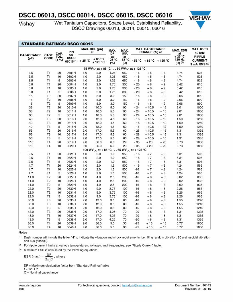
www.vishay.com For technical questions, contact: [email protected] Document Number: 40143198 Revision: 21-Jul-10
DSCC 06013, DSCC 06014, DSCC 06015, DSCC 06016Vishay Wet Tantalum Capacitors, Space Level, Established Reliability,
DSCC Drawings 06013, 06014, 06015, 06016
Notes(1) Dash number will include the letter “H” to indicate the vibration and shock requirements (i.e., 51 g random vibration, 80 g sinusoidal vibration
and 500 g shock).(2) For ripple current limits at various temperatures, voltages, and frequencies, see “Ripple Current” table.(3) Maximum ESR is calculated by the following equation:
DF = Maximum dissipation factor from “Standard Ratings” table f = 120 HzC = Nominal capacitance
STANDARD RATINGS: DSCC 06015
CAPACITANCE (µF)
CASE CODE
CAP. TOL. (± %)
PIN for
DSCC 06015 (1)
MAX. DCL (µA)at MAX.
DFat
+ 25 °C(%)
MAX. IMP.at
- 55 °C()
MAX. CAPACITANCE CHANGE (%) at MAX. ESR
at + 25 °C120 Hz() (2)
MAX. 85 °C40 kHzRIPPLE
CURRENT3 mA RMS (3)
+ 25 °C + 85 °C+ 125 °C - 55 °C + 85 °C + 125 °C
75 WVDC at + 85 °C . . . 50 WVDC at + 125 °C 3.5 T1 20 0601H 1.0 2.0 1.25 650 - 16 + 5 + 6 4.74 5253.5 T1 10 0602H 1.0 2.0 1.25 650 - 16 + 5 + 6 4.74 5253.5 T1 5 0603H 1.0 2.0 1.25 650 - 16 + 5 + 6 4.74 5256.8 T1 20 0604H 1.0 2.0 1.75 300 - 20 + 8 + 9 3.42 6106.8 T1 10 0605H 1.0 2.0 1.75 300 - 20 + 8 + 9 3.42 6106.8 T1 5 0606H 1.0 2.0 1.75 300 - 20 + 8 + 9 3.42 61015 T2 20 0607H 1.0 5.0 3.0 150 - 16 + 8 + 9 2.66 89015 T2 10 0608H 1.0 5.0 3.0 150 - 16 + 8 + 9 2.66 89015 T2 5 0609H 1.0 5.0 3.0 150 - 16 + 8 + 9 2.66 89033 T2 20 0610H 1.0 10.0 5.0 90 - 24 + 10.5 + 15 2.01 100033 T2 10 0611H 1.0 10.0 5.0 90 - 24 + 10.5 + 15 2.01 100033 T2 5 0612H 1.0 10.0 5.0 90 - 24 + 10.5 + 15 2.01 100040 T3 20 0613H 2.0 12.0 4.5 60 - 16 + 10.5 + 12 1.50 125040 T3 10 0614H 2.0 12.0 4.5 60 - 16 + 10.5 + 12 1.50 125040 T3 5 0615H 2.0 12.0 4.5 60 - 16 + 10.5 + 12 1.50 125056 T3 20 0616H 2.0 17.0 5.5 60 - 28 + 10.5 + 15 1.31 133556 T3 10 0617H 2.0 17.0 5.5 60 - 28 + 10.5 + 15 1.31 133556 T3 5 0618H 2.0 17.0 5.5 60 - 28 + 10.5 + 15 1.31 1335110 T4 20 0619H 9.0 36.0 6.0 29 - 35 + 20 + 20 0.73 1850110 T4 10 0620H 9.0 36.0 6.0 29 - 35 + 20 + 20 0.73 1850
100 WVDC at + 85 °C . . . 65 WVDC at + 125 °C 2.5 T1 20 0621H 1.0 2.0 1.0 950 - 16 + 7 + 8 5.31 5052.5 T1 10 0622H 1.0 2.0 1.0 950 - 16 + 7 + 8 5.31 5052.5 T1 5 0623H 1.0 2.0 1.0 950 - 16 + 7 + 8 5.31 5054.7 T1 20 0624H 1.0 2.0 1.5 500 - 16 + 7 + 8 4.24 5654.7 T1 10 0625H 1.0 2.0 1.5 500 -16 + 7 + 8 4.24 5654.7 T1 5 0626H 1.0 2.0 1.5 500 -16 + 7 + 8 4.24 56511.0 T2 20 0627H 1.0 4.0 2.5 200 -16 + 8 + 8 3.02 83511.0 T2 10 0628H 1.0 4.0 2.5 200 -16 + 8 + 8 3.02 83511.0 T2 5 0629H 1.0 4.0 2.5 200 -16 + 8 + 8 3.02 83522.0 T2 20 0630H 1.0 9.0 3.75 100 -16 + 8 + 8 2.26 96522.0 T2 10 0631H 1.0 9.0 3.75 100 -16 + 8 + 8 2.26 96522.0 T2 5 0632H 1.0 9.0 3.75 100 -16 + 8 + 8 2.26 96530.0 T3 20 0633H 2.0 12.0 3.5 80 -16 + 8 + 8 1.55 124030.0 T3 10 0634H 2.0 12.0 3.5 80 -16 + 8 + 8 1.55 124030.0 T3 5 0635H 2.0 12.0 3.5 80 -16 + 8 + 8 1.55 124043.0 T3 20 0636H 2.0 17.0 4.25 70 -20 + 8 + 8 1.31 133543.0 T3 10 0637H 2.0 17.0 4.25 70 -20 + 8 + 8 1.31 133543.0 T3 5 0638H 2.0 17.0 4.25 70 -20 + 8 + 8 1.31 133586.0 T4 20 0639H 9.0 36.0 5.0 30 -25 + 15 + 15 0.77 180086.0 T4 10 0640H 9.0 36.0 5.0 30 -25 + 15 + 15 0.77 1800
ESR (max.) DF
2 C-------------- where,=
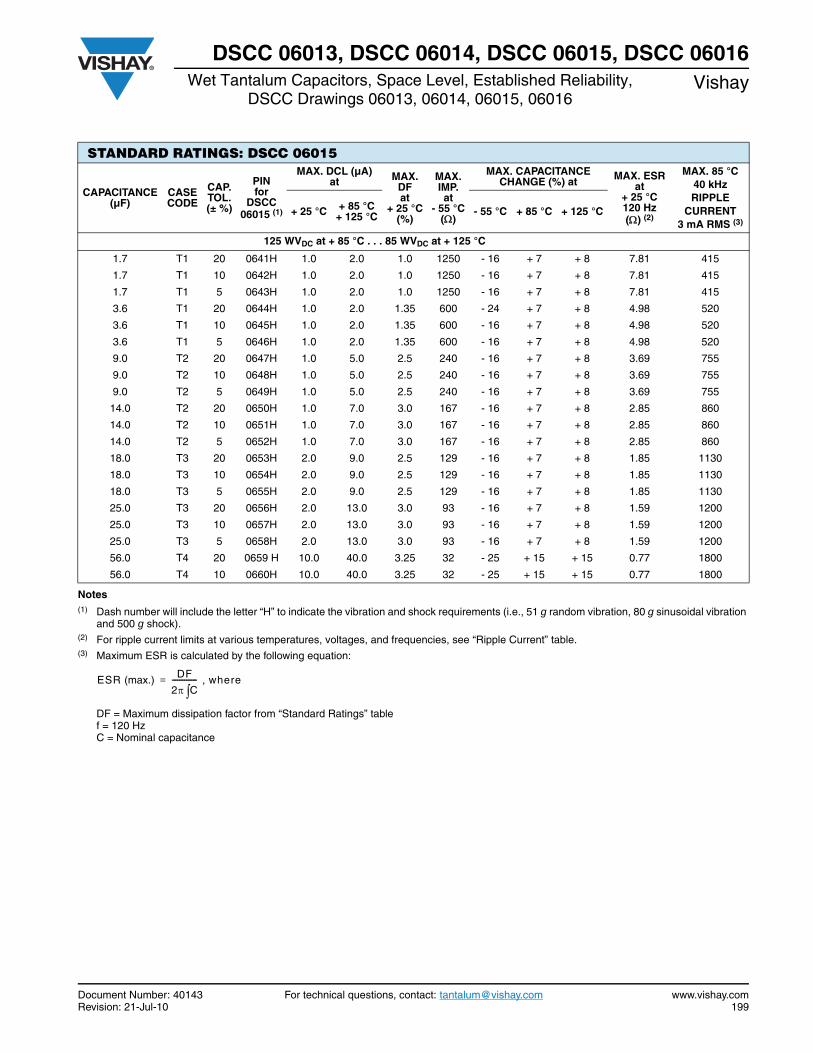
Document Number: 40143 For technical questions, contact: [email protected] www.vishay.comRevision: 21-Jul-10 199
DSCC 06013, DSCC 06014, DSCC 06015, DSCC 06016Wet Tantalum Capacitors, Space Level, Established Reliability,
DSCC Drawings 06013, 06014, 06015, 06016Vishay
Notes(1) Dash number will include the letter “H” to indicate the vibration and shock requirements (i.e., 51 g random vibration, 80 g sinusoidal vibration
and 500 g shock).(2) For ripple current limits at various temperatures, voltages, and frequencies, see “Ripple Current” table.(3) Maximum ESR is calculated by the following equation:
DF = Maximum dissipation factor from “Standard Ratings” table f = 120 HzC = Nominal capacitance
STANDARD RATINGS: DSCC 06015
CAPACITANCE (µF)
CASE CODE
CAP. TOL. (± %)
PIN for
DSCC 06015 (1)
MAX. DCL (µA)at MAX.
DFat
+ 25 °C(%)
MAX. IMP.at
- 55 °C()
MAX. CAPACITANCE CHANGE (%) at MAX. ESR
at + 25 °C120 Hz() (2)
MAX. 85 °C40 kHzRIPPLE
CURRENT3 mA RMS (3)
+ 25 °C + 85 °C+ 125 °C - 55 °C + 85 °C + 125 °C
125 WVDC at + 85 °C . . . 85 WVDC at + 125 °C
1.7 T1 20 0641H 1.0 2.0 1.0 1250 - 16 + 7 + 8 7.81 415
1.7 T1 10 0642H 1.0 2.0 1.0 1250 - 16 + 7 + 8 7.81 415
1.7 T1 5 0643H 1.0 2.0 1.0 1250 - 16 + 7 + 8 7.81 415
3.6 T1 20 0644H 1.0 2.0 1.35 600 - 24 + 7 + 8 4.98 520
3.6 T1 10 0645H 1.0 2.0 1.35 600 - 16 + 7 + 8 4.98 520
3.6 T1 5 0646H 1.0 2.0 1.35 600 - 16 + 7 + 8 4.98 520
9.0 T2 20 0647H 1.0 5.0 2.5 240 - 16 + 7 + 8 3.69 755
9.0 T2 10 0648H 1.0 5.0 2.5 240 - 16 + 7 + 8 3.69 755
9.0 T2 5 0649H 1.0 5.0 2.5 240 - 16 + 7 + 8 3.69 755
14.0 T2 20 0650H 1.0 7.0 3.0 167 - 16 + 7 + 8 2.85 860
14.0 T2 10 0651H 1.0 7.0 3.0 167 - 16 + 7 + 8 2.85 860
14.0 T2 5 0652H 1.0 7.0 3.0 167 - 16 + 7 + 8 2.85 860
18.0 T3 20 0653H 2.0 9.0 2.5 129 - 16 + 7 + 8 1.85 1130
18.0 T3 10 0654H 2.0 9.0 2.5 129 - 16 + 7 + 8 1.85 1130
18.0 T3 5 0655H 2.0 9.0 2.5 129 - 16 + 7 + 8 1.85 1130
25.0 T3 20 0656H 2.0 13.0 3.0 93 - 16 + 7 + 8 1.59 1200
25.0 T3 10 0657H 2.0 13.0 3.0 93 - 16 + 7 + 8 1.59 1200
25.0 T3 5 0658H 2.0 13.0 3.0 93 - 16 + 7 + 8 1.59 1200
56.0 T4 20 0659 H 10.0 40.0 3.25 32 - 25 + 15 + 15 0.77 1800
56.0 T4 10 0660H 10.0 40.0 3.25 32 - 25 + 15 + 15 0.77 1800
ESR (max.) DF
2 C-------------- where,=
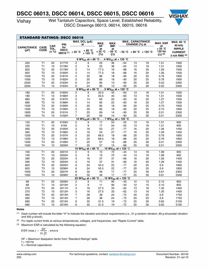
www.vishay.com For technical questions, contact: [email protected] Document Number: 40143200 Revision: 21-Jul-10
DSCC 06013, DSCC 06014, DSCC 06015, DSCC 06016Vishay Wet Tantalum Capacitors, Space Level, Established Reliability,
DSCC Drawings 06013, 06014, 06015, 06016
Notes(1) Dash number will include the letter “H” to indicate the vibration and shock requirements (i.e., 51 g random vibration, 80 g sinusoidal vibration
and 500 g shock).(2) For ripple current limits at various temperatures, voltages, and frequencies, see “Ripple Current” table.(3) Maximum ESR is calculated by the following equation:
DF = Maximum dissipation factor from “Standard Ratings” table f = 120 HzC = Nominal capacitance
STANDARD RATINGS: DSCC 06016
CAPACITANCE (µF)
CASE CODE
CAP. TOL. (± %)
PINfor
DSCC 06016 (1)
MAX. DCL (µA)at MAX.
DFat
+ 25 °C(%)
MAX. IMP.at
- 55 °C()
MAX.. CAPACITANCE CHANGE (%) at MAX. ESR
at+ 25 °C 120 Hz() (2)
MAX. 85 °C40 kHzRIPPLE
CURRENT3 mA RMS (3)
+ 25 °C + 85 °C+ 125 °C - 55 °C + 85 °C + 125 °C
6 WVDC at + 85 °C . . .4 WVDC at + 125 °C 220 T1 20 0177H 2 9 25 36 - 64 13 16 1.51 1000220 T1 10 0178H 2 9 25 36 - 64 13 16 1.51 1000820 T2 20 0179H 3 14 77.5 18 - 88 16 20 1.26 1500820 T2 10 0180H 3 14 77.5 18 - 88 16 20 1.26 15001500 T3 20 0181H 5 20 86 18 - 90 20 25 0.76 19001500 T3 10 0182H 5 20 86 18 - 90 20 25 0.76 19002200 T4 20 0183H 6 24 85 13 - 90 25 30 0.52 23002200 T4 10 0184H 6 24 85 13 - 90 25 30 0.52 2300
8 WVDC at + 85 °C . . . 5 WVDC at + 125 °C180 T1 20 0185H 2 9 20.5 45 - 60 13 16 1.51 1000180 T1 10 0186H 2 9 20.5 45 - 60 13 16 1.51 1000680 T2 20 0187H 3 14 65 22 - 83 16 20 1.27 1500680 T2 10 0188H 3 14 65 22 - 83 16 20 1.27 15001500 T3 20 0189H 5 20 85 18 - 90 20 25 0.75 19001500 T3 10 0190H 5 20 85 18 - 90 20 25 0.75 19001800 T4 20 0191H 7 25 69 14 - 90 25 30 0.51 23001800 T4 10 0192H 7 25 69 14 - 90 25 30 0.51 2300
10 WVDCat + 85 °C . . . 7 WVDC at + 125 °C 150 T1 20 0193H 2 9 17 54 - 55 13 16 1.51 900150 T1 10 0194 2 9 17 54 - 55 13 16 1.51 900560 T2 20 0195H 3 16 53 27 - 77 16 20 1.26 1450560 T2 10 0196H 3 16 53 27 - 77 16 20 1.26 14501200 T3 20 0197H 5 20 68.5 18 - 88 20 25 0.76 18501200 T3 10 0198H 5 20 68.5 18 - 88 20 25 0.76 18501500 T4 20 0199H 7 25 57 15 - 88 25 30 0.51 23001500 T4 10 0200H 7 25 57 15 - 88 25 30 0.51 2300
15 WVDC at + 85 °C . . . 10 WVDC at + 125 °C 100 T1 20 0201H 2 9 15 72 - 44 13 16 1.99 900100 T1 10 0202H 2 9 15 72 - 44 13 16 1.99 900390 T2 20 0203H 3 16 37 31 - 66 16 20 1.26 1450390 T2 10 0204H 3 16 37 31 - 66 16 20 1.26 1450820 T3 20 0205H 6 24 55.5 22 - 77 20 25 0.9 1800820 T3 10 0206H 6 24 55.5 22 - 77 20 25 0.9 18001000 T4 20 0207H 8 32 46 17 - 77 25 30 0.61 23001000 T4 10 0208H 8 32 46 17 - 77 25 30 0.61 2300
25 WVDC at + 85 °C . . . 15 WVDC at + 125 °C 68 T1 20 0209H 2 9 11 90 - 40 12 15 2.15 85068 T1 10 0210H 2 9 11 90 - 40 12 15 2.15 850270 T2 20 0211H 3 16 27.5 33 - 62 13 16 1.35 1400270 T2 10 0212H 3 16 27.5 33 - 62 13 16 1.35 1400560 T3 20 0213H 7 28 38 24 - 72 20 25 0.9 1750560 T3 10 0214H 7 28 38 24 - 72 20 25 0.9 1750680 T4 20 0215H 8 32 31.5 19 - 72 25 30 0.62 2100680 T4 10 0216H 8 32 31.5 19 - 72 25 30 0.62 2100
ESR (max.) DF
2 C-------------- where,=
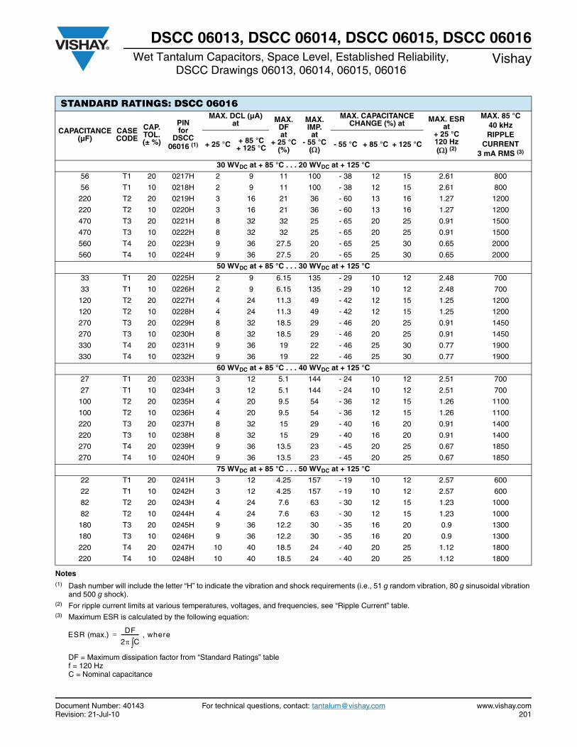
Document Number: 40143 For technical questions, contact: [email protected] www.vishay.comRevision: 21-Jul-10 201
DSCC 06013, DSCC 06014, DSCC 06015, DSCC 06016Wet Tantalum Capacitors, Space Level, Established Reliability,
DSCC Drawings 06013, 06014, 06015, 06016Vishay
Notes(1) Dash number will include the letter “H” to indicate the vibration and shock requirements (i.e., 51 g random vibration, 80 g sinusoidal vibration
and 500 g shock).(2) For ripple current limits at various temperatures, voltages, and frequencies, see “Ripple Current” table.(3) Maximum ESR is calculated by the following equation:
DF = Maximum dissipation factor from “Standard Ratings” table f = 120 HzC = Nominal capacitance
STANDARD RATINGS: DSCC 06016
CAPACITANCE (µF)
CASE CODE
CAP. TOL. (± %)
PINfor
DSCC 06016 (1)
MAX. DCL (µA)at MAX.
DFat
+ 25 °C(%)
MAX. IMP.at
- 55 °C()
MAX. CAPACITANCE CHANGE (%) at MAX. ESR
at+ 25 °C120 Hz() (2)
MAX. 85 °C40 kHzRIPPLE
CURRENT3 mA RMS (3)
+ 25 °C + 85 °C+ 125 °C - 55 °C + 85 °C + 125 °C
30 WVDC at + 85 °C . . . 20 WVDC at + 125 °C
56 T1 20 0217H 2 9 11 100 - 38 12 15 2.61 800
56 T1 10 0218H 2 9 11 100 - 38 12 15 2.61 800
220 T2 20 0219H 3 16 21 36 - 60 13 16 1.27 1200
220 T2 10 0220H 3 16 21 36 - 60 13 16 1.27 1200
470 T3 20 0221H 8 32 32 25 - 65 20 25 0.91 1500
470 T3 10 0222H 8 32 32 25 - 65 20 25 0.91 1500
560 T4 20 0223H 9 36 27.5 20 - 65 25 30 0.65 2000
560 T4 10 0224H 9 36 27.5 20 - 65 25 30 0.65 2000
50 WVDC at + 85 °C . . . 30 WVDC at + 125 °C
33 T1 20 0225H 2 9 6.15 135 - 29 10 12 2.48 700
33 T1 10 0226H 2 9 6.15 135 - 29 10 12 2.48 700
120 T2 20 0227H 4 24 11.3 49 - 42 12 15 1.25 1200
120 T2 10 0228H 4 24 11.3 49 - 42 12 15 1.25 1200
270 T3 20 0229H 8 32 18.5 29 - 46 20 25 0.91 1450
270 T3 10 0230H 8 32 18.5 29 - 46 20 25 0.91 1450
330 T4 20 0231H 9 36 19 22 - 46 25 30 0.77 1900
330 T4 10 0232H 9 36 19 22 - 46 25 30 0.77 1900
60 WVDC at + 85 °C . . . 40 WVDC at + 125 °C
27 T1 20 0233H 3 12 5.1 144 - 24 10 12 2.51 700
27 T1 10 0234H 3 12 5.1 144 - 24 10 12 2.51 700
100 T2 20 0235H 4 20 9.5 54 - 36 12 15 1.26 1100
100 T2 10 0236H 4 20 9.5 54 - 36 12 15 1.26 1100
220 T3 20 0237H 8 32 15 29 - 40 16 20 0.91 1400
220 T3 10 0238H 8 32 15 29 - 40 16 20 0.91 1400
270 T4 20 0239H 9 36 13.5 23 - 45 20 25 0.67 1850
270 T4 10 0240H 9 36 13.5 23 - 45 20 25 0.67 1850
75 WVDC at + 85 °C . . . 50 WVDC at + 125 °C
22 T1 20 0241H 3 12 4.25 157 - 19 10 12 2.57 600
22 T1 10 0242H 3 12 4.25 157 - 19 10 12 2.57 600
82 T2 20 0243H 4 24 7.6 63 - 30 12 15 1.23 1000
82 T2 10 0244H 4 24 7.6 63 - 30 12 15 1.23 1000
180 T3 20 0245H 9 36 12.2 30 - 35 16 20 0.9 1300
180 T3 10 0246H 9 36 12.2 30 - 35 16 20 0.9 1300
220 T4 20 0247H 10 40 18.5 24 - 40 20 25 1.12 1800
220 T4 10 0248H 10 40 18.5 24 - 40 20 25 1.12 1800
ESR (max.) DF
2 C-------------- where,=
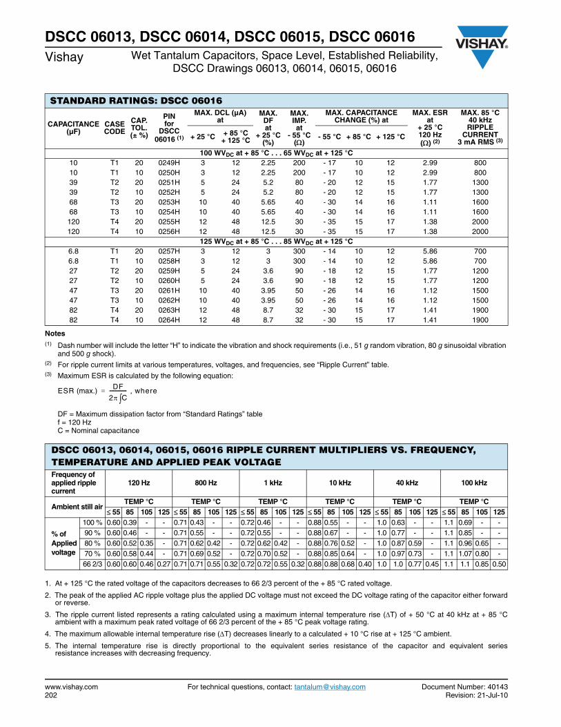
www.vishay.com For technical questions, contact: [email protected] Document Number: 40143202 Revision: 21-Jul-10
DSCC 06013, DSCC 06014, DSCC 06015, DSCC 06016Vishay Wet Tantalum Capacitors, Space Level, Established Reliability,
DSCC Drawings 06013, 06014, 06015, 06016
Notes(1) Dash number will include the letter “H” to indicate the vibration and shock requirements (i.e., 51 g random vibration, 80 g sinusoidal vibration
and 500 g shock).(2) For ripple current limits at various temperatures, voltages, and frequencies, see “Ripple Current” table.(3) Maximum ESR is calculated by the following equation:
DF = Maximum dissipation factor from “Standard Ratings” table f = 120 HzC = Nominal capacitance
STANDARD RATINGS: DSCC 06016
CAPACITANCE (µF)
CASE CODE
CAP. TOL. (± %)
PINfor
DSCC 06016 (1)
MAX. DCL (µA)at
MAX. DFat
+ 25 °C(%)
MAX. IMP.at
- 55 °C()
MAX. CAPACITANCE CHANGE (%) at
MAX. ESRat
+ 25 °C 120 Hz() (2)
MAX. 85 °C40 kHzRIPPLE
CURRENT3 mA RMS (3)+ 25 °C + 85 °C
+ 125 °C - 55 °C + 85 °C + 125 °C
100 WVDC at + 85 °C . . . 65 WVDC at + 125 °C 10 T1 20 0249H 3 12 2.25 200 - 17 10 12 2.99 80010 T1 10 0250H 3 12 2.25 200 - 17 10 12 2.99 80039 T2 20 0251H 5 24 5.2 80 - 20 12 15 1.77 130039 T2 10 0252H 5 24 5.2 80 - 20 12 15 1.77 130068 T3 20 0253H 10 40 5.65 40 - 30 14 16 1.11 160068 T3 10 0254H 10 40 5.65 40 - 30 14 16 1.11 1600120 T4 20 0255H 12 48 12.5 30 - 35 15 17 1.38 2000120 T4 10 0256H 12 48 12.5 30 - 35 15 17 1.38 2000
125 WVDC at + 85 °C . . . 85 WVDC at + 125 °C 6.8 T1 20 0257H 3 12 3 300 - 14 10 12 5.86 7006.8 T1 10 0258H 3 12 3 300 - 14 10 12 5.86 70027 T2 20 0259H 5 24 3.6 90 - 18 12 15 1.77 120027 T2 10 0260H 5 24 3.6 90 - 18 12 15 1.77 120047 T3 20 0261H 10 40 3.95 50 - 26 14 16 1.12 150047 T3 10 0262H 10 40 3.95 50 - 26 14 16 1.12 150082 T4 20 0263H 12 48 8.7 32 - 30 15 17 1.41 190082 T4 10 0264H 12 48 8.7 32 - 30 15 17 1.41 1900
ESR (max.) DF
2 C-------------- where,=
DSCC 06013, 06014, 06015, 06016 RIPPLE CURRENT MULTIPLIERS VS. FREQUENCY, TEMPERATURE AND APPLIED PEAK VOLTAGE Frequency of applied ripple current
120 Hz 800 Hz 1 kHz 10 kHz 40 kHz 100 kHz
Ambient still airTEMP °C TEMP °C TEMP °C TEMP °C TEMP °C TEMP °C
55 85 105 125 55 85 105 125 55 85 105 125 55 85 105 125 55 85 105 125 55 85 105 125
% of Applied voltage
100 % 0.60 0.39 - - 0.71 0.43 - - 0.72 0.46 - - 0.88 0.55 - - 1.0 0.63 - - 1.1 0.69 - - 90 % 0.60 0.46 - - 0.71 0.55 - - 0.72 0.55 - - 0.88 0.67 - - 1.0 0.77 - - 1.1 0.85 - - 80 % 0.60 0.52 0.35 - 0.71 0.62 0.42 - 0.72 0.62 0.42 - 0.88 0.76 0.52 - 1.0 0.87 0.59 - 1.1 0.96 0.65 - 70 % 0.60 0.58 0.44 - 0.71 0.69 0.52 - 0.72 0.70 0.52 - 0.88 0.85 0.64 - 1.0 0.97 0.73 - 1.1 1.07 0.80 - 66 2/3 0.60 0.60 0.46 0.27 0.71 0.71 0.55 0.32 0.72 0.72 0.55 0.32 0.88 0.88 0.68 0.40 1.0 1.0 0.77 0.45 1.1 1.1 0.85 0.50
1. At + 125 °C the rated voltage of the capacitors decreases to 66 2/3 percent of the + 85 °C rated voltage.
2. The peak of the applied AC ripple voltage plus the applied DC voltage must not exceed the DC voltage rating of the capacitor either forwardor reverse.
3. The ripple current listed represents a rating calculated using a maximum internal temperature rise (T) of + 50 °C at 40 kHz at + 85 °Cambient with a maximum peak rated voltage of 66 2/3 percent of the + 85 °C peak voltage rating.
4. The maximum allowable internal temperature rise (T) decreases linearly to a calculated + 10 °C rise at + 125 °C ambient.
5. The internal temperature rise is directly proportional to the equivalent series resistance of the capacitor and equivalent seriesresistance increases with decreasing frequency.
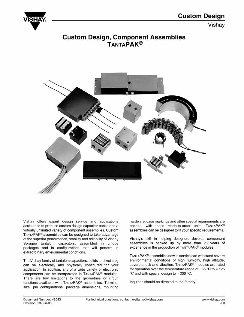
Document Number: 42083 For technical questions, contact: [email protected] www.vishay.comRevision: 13-Jun-05 203
Custom Design, Component Assemblies TANTAPAK®
Custom DesignVishay
Vishay offers expert design service and applicationsassistance to produce custom design capacitor banks and avirtually unlimited variety of component assemblies. CustomTANTAPAK® assemblies can be designed to take advantageof the superior performance, stability and reliability of VishaySprague tantalum capacitors, assembled in uniquepackages and in configurations that will perform inextraordinary environmental conditions.
The Vishay family of tantalum capacitors, solids and wet slugcan be electrically and physically configured for yourapplication. In addition, any of a wide variety of electroniccomponents can be incorporated in TANTAPAK® modules.There are few limitations to the geometries or circuitfunctions available with TANTAPAK® assemblies. Terminalsize, pin configurations, package dimensions, mounting
hardware, case markings and other special requirements areoptional with these made-to-order units. TANTAPAK®
assemblies can be designed to fit your specific requirements.
Vishay's skill in helping designers develop componentassemblies is backed up by more than 25 years ofexperience in the production of TANTAPAK® modules.
TANTAPAK® assemblies now in service can withstand severeenvironmental conditions of high humidity, high altitude,severe shock and vibration. TANTAPAK® modules are ratedfor operation over the temperature range of - 55 °C to + 125°C and with special design to + 200 °C.
Inquiries should be directed to the factory.
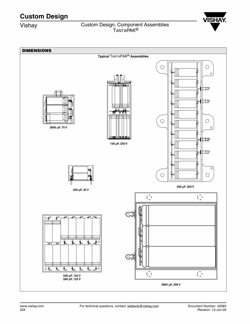
Custom DesignVishay Custom Design, Component Assemblies
TANTAPAK®
www.vishay.com For technical questions, contact: [email protected] Document Number: 42083204 Revision: 13-Jun-05
DIMENSIONSTypical TANTAPAK® Assemblies
2600 µF, 75 V
150 µF, 250 V
350 µF, 250 V250 µF, 35 V
500 µF, 125 V280 µF, 125 V
2800 µF, 200 V
WORLDWIDE SALES CONTACTS
Visit www.vishay.com for product information or select below for a current list of sales offices, representatives, and distributors.
THE AMERICASUNITED STATESVISHAY AMERICAS ONE GREENWICH PLACE SHELTON, CT 06484 UNITED STATES PH: +1-402-563-6866 FAX: +1-402-563-6296
ASIASINGAPOREVISHAY INTERTECHNOLOGY ASIA PTE LTD.37A TAMPINES STREET 92 #07-00SINGAPORE 528886 PH: +65-6788-6668 FAX: +65-6788-0988
P.R. CHINAVISHAY CHINA CO., LTD.15D, SUN TONG INFOPORT PLAZA55 HUAI HAI WEST ROADSHANGHAI 200030 P.R. CHINAPH: +86-21-5258 5000FAX: +86-21-5258 7979
JAPANVISHAY JAPAN CO., LTD.SHIBUYA PRESTIGE BLDG. 4F 3-12-22, SHIBUYA SHIBUYA-KU TOKYO 150-0002 JAPAN PH: +81-3-5466-7150 FAX: +81-3-5466-7160
EUROPEGERMANYVISHAY ELECTRONIC GMBHGEHEIMRAT-ROSENTHAL-STR. 100 95100 SELB GERMANY PH: +49-9287-71-0 FAX: +49-9287-70435 FRANCEVISHAY S.A.199, BLVD DE LA MADELEINE 06003 NICE, CEDEX 1 FRANCE PH: +33-4-9337-2727 FAX: +33-4-9337-2726 UNITED KINGDOMVISHAY LTD.SUITE 6C, TOWER HOUSEST. CATHERINE’S COURTSUNDERLAND ENTERPRISE PARKSUNDERLAND SR5 3XJ UNITED KINGDOMPH: +44-191-516-8584FAX: +44-191-549-9556
Buildinto your
VishayDesign
Discrete Semiconductors and Passive ComponentsOne of the World’s Largest Manufacturers of
World HeadquartersVishay Intertechnology, Inc.63 Lancaster AvenueMalvern, PA 19355-2143United States
w w w . v i s h a y . c o m
DA
TA
BO
OK
WE
T T
AN
TA
LU
M C
AP
AC
ITO
RS
Discrete Semiconductors and Passive ComponentsOne of the World’s Largest Manufacturers of
VSE-DB0030-11 e
© Copyright 2011 Vishay Intertechnology, Inc.
® Registered trademarks of Vishay Intertechnology, Inc.
All rights reserved. Printed in Germany.
Specifications subject to change without notice.