Embed Size (px)
Citation preview

Vision sensors SBSI and compact vision systems SBO…-Q
Productivity in focus

2
You want a reliable solution for identifying products.You demand 100% quality output.We have the right vision for achieving maximum productivity.
Versatile use, reliable action
Designed for nearly all industry sectors and applications. Let us to inspire you: where and how you can use the vision systems is explained from page 4 onwards.
Page 4
Vision sensor SBSI for simple applications
Inexpensive and quick to commission. High performance with code reader SBSI-B for 1D and 2D codes or reliability with object sensor SBSI-Q for simple quality inspection and position sensing (see page 8).
Page 8 SBSI

3
The prerequisite: maximum process reliability. The goal: 100% quality output. The method: maximised productivity.
Machine vision systems from Festo make a decisive contribution to ensuring that the input and output are right. They monitor and stabilise processes, whether they’re reading codes or detecting positions for handling tasks. In some cases they even control the process itself. And they inspect quality from when the goods come in to when they are finished.
That makes your work easier. It makes your machines and systems more productive and flexible. And it further optimises the use of materials.
Your productivity in focus: with industrial image processing from Festo
Maximum functionality: flexible vision system SBO…-Q
A single device for every situation thanks to comprehensive evaluation options and flexible communication. There’s even an integrated PLC with embedded CODESYS 2.3 for control via the camera. Go to page 15 to discover some fascinating technology.
Page 15
The complete range at a glance
When speed is of the essence: you’ll find our extensive range of SBSI and SBO products beginning on page 26.
Page 26SB0...-Q
flexible
simple

4
Image processing increases productivity. In nearly all industry sectors, in almost any application. Vision systems SBO...-Q and vision sensors SBSI are used in very different industries and for a wide variety of purposes. Below you’ll find a few applications.
Increase your efficiency by integrating image processing in the application
Products Industry sectors
The main applications Code
read
er
SBSI
-B
Obj
ect s
enso
r SB
SI-Q
Com
pact
vis
ion
syst
em
SBO
...-Q
Auto
mot
ive
and
Tier
1 s
uppl
iers
indu
stry
Sem
icon
duct
or in
dust
ry a
nd e
lect
roni
cs
Food
and
bev
erag
e
Smal
l par
ts a
ssem
bly
Labo
rato
ry a
utom
atio
n
Cons
umer
goo
ds a
nd c
osm
etic
s
End
line
pack
agin
g
Bio
tech
nolo
gy a
nd p
harm
aceu
tical
s
Pick & place
Position and rotary orientation detection – – • • • • • • • • –
Quality inspection
Checking for presence/completeness •* • • • • • • • • • •Fill-level monitoring – • • – – • – • • • •Printing/labelling inspection •* • • • • • • • • • •Measuring parts – •** • • • • • • • • –
Position inspection •* • • • • • • • • • •Identification
Reading 1D codes • – • • • • • • • • •Reading 2D codes • – • • • • • • • • •Text recognition (OCR) – – • • • • • • • • •
* Can be checked via the code ** Rough estimate of length is possible
• Frequently used • Occasionally used
5
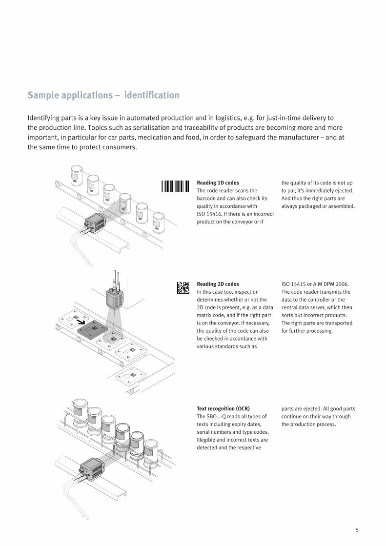
Identifying parts is a key issue in automated production and in logistics, e.g. for just-in-time delivery to the production line. Topics such as serialisation and traceability of products are becoming more and more important, in particular for car parts, medication and food, in order to safeguard the manufacturer – and at the same time to protect consumers.
Sample applications – identification
Reading 1D codesThe code reader scans the barcode and can also check its quality in accordance with ISO 15416. If there is an incorrect product on the conveyor or if
the quality of its code is not up to par, it’s immediately ejected. And thus the right parts are always packaged or assembled.
Reading 2D codesIn this case too, inspection determines whether or not the 2D code is present, e.g. as a data matrix code, and if the right part is on the conveyor. If necessary, the quality of the code can also be checked in accordance with various standards such as
ISO 15415 or AIM DPM 2006. The code reader transmits the data to the controller or the central data server, which then sorts out incorrect products. The right parts are transported for further processing.
Text recognition (OCR) The SBO…-Q reads all types of texts including expiry dates, serial numbers and type codes.Illegible and incorrect texts are detected and the respective
parts are ejected. All good parts continue on their way through the production process.
6
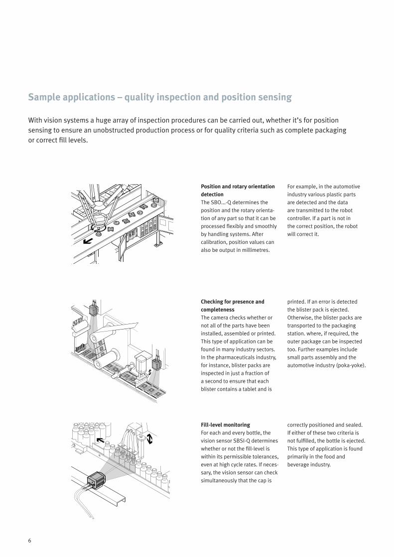
With vision systems a huge array of inspection procedures can be carried out, whether it’s for position sensing to ensure an unobstructed production process or for quality criteria such as complete packaging or correct fill levels.
Sample applications – quality inspection and position sensing
Position and rotary orientation detectionThe SBO...-Q determines the position and the rotary orienta-tion of any part so that it can be processed flexibly and smoothly by handling systems. After calibration, position values can also be output in millimetres.
For example, in the automotive industry various plastic parts are detected and the data are transmitted to the robot controller. If a part is not in the correct position, the robot will correct it.
Checking for presence and completenessThe camera checks whether or not all of the parts have been installed, assembled or printed. This type of application can be found in many industry sectors. In the pharmaceuticals industry, for instance, blister packs are inspected in just a fraction of a second to ensure that each blister contains a tablet and is
printed. If an error is detected the blister pack is ejected. Otherwise, the blister packs are transported to the packaging station. where, if required, the outer package can be inspected too. Further examples include small parts assembly and the automotive industry (poka-yoke).
Fill-level monitoring For each and every bottle, the vision sensor SBSI-Q determines whether or not the fill-level is within its permissible tolerances, even at high cycle rates. If neces-sary, the vision sensor can check simultaneously that the cap is
correctly positioned and sealed. If either of these two criteria is not fulfilled, the bottle is ejected. This type of application is found primarily in the food and beverage industry.

7
Printing and labelling inspectionThe vision sensor analyses whether or not the label and the printing are present and correctly positioned. If required, the lid can be inspected at the same time. The vision sensor checks
these criteria very quickly. If any of them has not been fulfilled, the container is ejected. This type of application can be found, amongst others, in the food and consumer goods industries.
Measuring parts The SBO…-Q can measure parts extremely accurately and, once calibrated, can output measured values in millimetres. If the measured value is not within the specified tolerance, the parts are ejected. Small parts assembly
and the automotive industry are some of the industries in which part measurements are carried out. The object sensor SBSI-Q is also capable of roughly estimating lengths.
Position detection The vision sensor monitors whether or not the part has been mounted within the required tolerance levels. Assembly errors are reliably detected and
defective parts are ejected. This type of application can be found in nearly all industries, such as the automotive and consumer goods sectors.
8
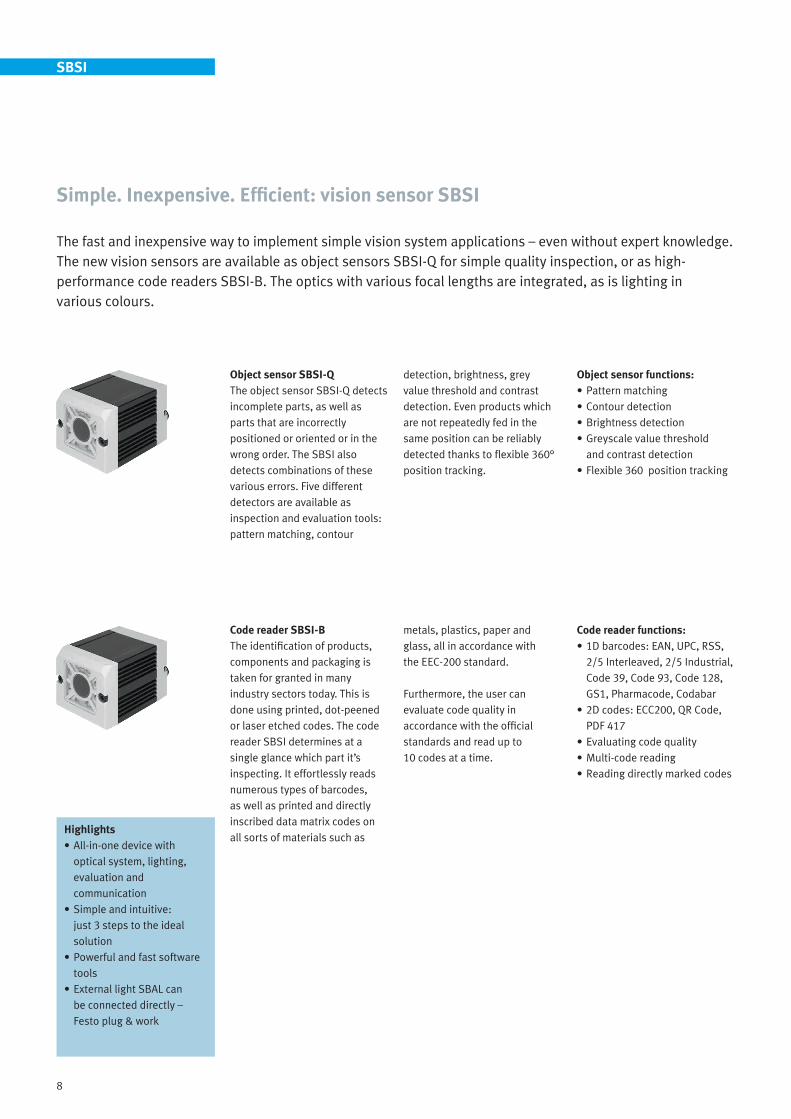
The fast and inexpensive way to implement simple vision system applications – even without expert knowledge. The new vision sensors are available as object sensors SBSI-Q for simple quality inspection, or as high-performance code readers SBSI-B. The optics with various focal lengths are integrated, as is lighting in various colours.
Simple. Inexpensive. Efficient: vision sensor SBSI
Object sensor SBSI-QThe object sensor SBSI-Q detects incomplete parts, as well as parts that are incorrectly positioned or oriented or in the wrong order. The SBSI also detects combinations of these various errors. Five different detectors are available as inspection and evaluation tools: pattern matching, contour
detection, brightness, grey value threshold and contrast detection. Even products which are not repeatedly fed in the same position can be reliably detected thanks to flexible 360° position tracking.
Object sensor functions:• Pattern matching• Contour detection• Brightness detection• Greyscale value threshold
and contrast detection• Flexible 360 position tracking
Code reader SBSI-BThe identification of products, components and packaging is taken for granted in many industry sectors today. This is done using printed, dot-peened or laser etched codes. The code reader SBSI determines at a single glance which part it’s inspecting. It effortlessly reads numerous types of barcodes, as well as printed and directly inscribed data matrix codes on all sorts of materials such as
metals, plastics, paper and glass, all in accordance with the EEC-200 standard.
Furthermore, the user can evaluate code quality in accordance with the official standards and read up to 10 codes at a time.
Code reader functions:• 1D barcodes: EAN, UPC, RSS,
2/5 Interleaved, 2/5 Industrial, Code 39, Code 93, Code 128, GS1, Pharmacode, Codabar
• 2D codes: ECC200, QR Code, PDF 417
• Evaluating code quality• Multi-code reading• Reading directly marked codes
SBSI
Highlights• All-in-one device with
optical system, lighting, evaluation and communication
• Simple and intuitive: just 3 steps to the ideal solution
• Powerful and fast software tools
• External light SBAL can be connected directly – Festo plug & work

9
It couldn’t be any easier: only three steps are needed to commission the vision sensor SBSI. Matching software tools considerably simplify the procedure so that it can be carried out without any expert knowledge.
Quick commissioning and intuitive operation with the vision sensor SBSI
1. Connecting The vision sensor is connected to a PC or a notebook via Ethernet. Start the “SBSI Vision Sensor” software in order to find the sensor in the Ethernet network. An overview of all devices available within the network then appears in the “VS Device Manager”. You can actively scan the network for devices if necessary. Once you’ve found the right device, you can configure it. It is also possible to simulate the various device models offline.
2. Configuring the jobYou can configure the inspection program/job in just a few steps in the “VS Configuration Studio” (see image below). There is also an option to set up flexible 360 position tracking if the parts to be inspected cannot be fed in the right position.
3. Displaying resultsAfter the SBSI has been configured, you can display the results in the “VS Visualisation Studio” during operation. If necessary, you can also switch back and forth between different jobs – a real advantage when it comes to flexibility.
It just takes a few steps to create an inspection program:
• Job: optimise the camera image and general settings (including auto-shutter function).
• Position tracking (optional): in the event that the position of the part changes, 360° position tracking can be selected for the SBSI-Q. This is taken care of automatically by the SBSI-B with its code reading tools.
• Detectors: this is where suitable tools can be selected.
• Output: configuring the communication interfaces for output of the results.
SBSI

10
The vision sensor SBSI takes on many tasks. The SBSI-Q offers the option of flexible 360° position tracking if the part to be inspected cannot be fed in the right position. The fast, high-performance detectors are introduced on the following pages.
Many detectors – one vision sensor
SBSI
Detectors Screen SBSI-B SBSI-Q
Position tracking The actual position of the inspection part can optionally be detected by its contour. All detectors are then automatically aligned with the detected position.
– •
Pattern matchingThis detector is suitable for identifying taught-in patterns of any shape, even without clear edges or contours.
– •
ContourThis detector compares the contour of a taught-in part with the part being tested. Position and rotary orientation can also be output.
– •
ContrastThis detector determines the contrast of the selected search area, i.e. it evaluates the differences between the greyscale values of the respective pixels.
– •
✔ ✗
✔ ✗
✔ ✗

11
SBSI
Detectors Screen SBSI-B SBSI-Q
BrightnessThis detector determines the average of the greyscale values in the search area.
– •
Greyscale value thresholdThis detector counts all the pixels in the search area within the specified range of greyscale values.
– •
BarcodeReading various 1D codes such as EAN, Code 39, etc. – with integrated position detection, quality inspection and multi-code reading.
• –
2D codeReading data matrix codes, QR Codes and PDF codes – with integrated position detection, quality inspection and multi-code reading.
• –
✔ ✗
✔ ✗
12
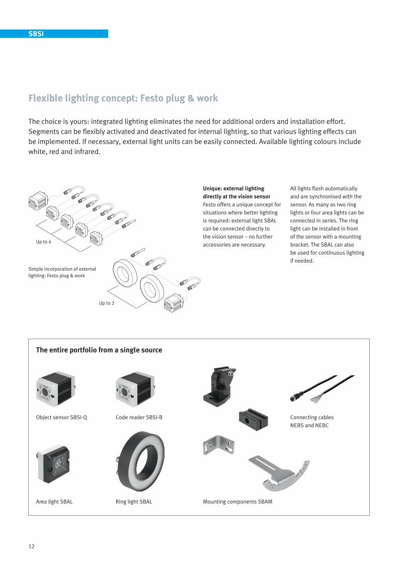
The choice is yours: integrated lighting eliminates the need for additional orders and installation effort. Segments can be flexibly activated and deactivated for internal lighting, so that various lighting effects can be implemented. If necessary, external light units can be easily connected. Available lighting colours include white, red and infrared.
Flexible lighting concept: Festo plug & work
Unique: external lighting directly at the vision sensorFesto offers a unique concept for situations where better lighting is required: external light SBAL can be connected directly to the vision sensor – no further accessories are necessary.
The entire portfolio from a single source
Connecting cables NEBS and NEBC
Area light SBAL Mounting components SBAM
Simple incorporation of external lighting: Festo plug & work
Object sensor SBSI-Q Code reader SBSI-B
Ring light SBAL
All lights flash automatically and are synchronised with the sensor. As many as two ring lights or four area lights can be connected in series. The ring light can be installed in front of the sensor with a mounting bracket. The SBAL can also be used for continuous lighting if needed.
SBSI
Up to 4
Up to 2
13
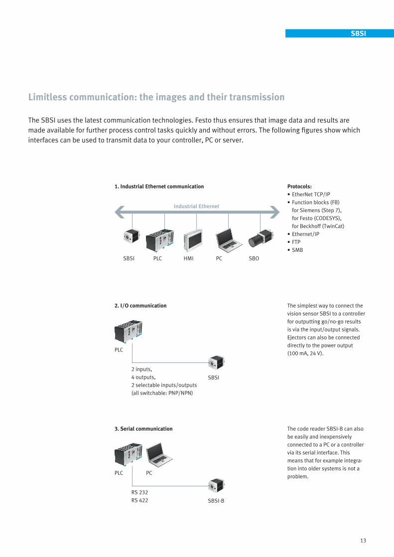
The SBSI uses the latest communication technologies. Festo thus ensures that image data and results are made available for further process control tasks quickly and without errors. The following figures show which interfaces can be used to transmit data to your controller, PC or server.
Limitless communication: the images and their transmission
1. Industrial Ethernet communication Protocols:• EtherNet TCP/IP• Function blocks (FB)
for Siemens (Step 7), for Festo (CODESYS), for Beckhoff (TwinCat)
• Ethernet/IP• FTP• SMB
2. I/O communication The simplest way to connect the vision sensor SBSI to a controller for outputting go/no-go results is via the input/output signals. Ejectors can also be connected directly to the power output (100 mA, 24 V).
Industrial Ethernet
SBSI PLC HMI PC SBO
2 inputs,4 outputs,2 selectable inputs/outputs (all switchable: PNP/NPN)
PLC
SBSI
The code reader SBSI-B can also be easily and inexpensively connected to a PC or a controller via its serial interface. This means that for example integra-tion into older systems is not a problem.
3. Serial communication
RS 232RS 422
PLC PC
SBSI-B
SBSI

14
General data, vision sensor SBSI
Lighting Integrated or with option for easy connection of external lightingColours: white, red, infrared (depending on model)
Optical system IntegratedFocal lengths (depending on model):f = 6 mm (working distance: 6 mm ... infinity, field of vision: min. 5 x 4 mm)
-150
150
-100
100
-50
50
0
150 200 250 300100500
Working distance [mm]
Fiel
d of
vis
ion
[mm
]
f = 12 mm (working distance: 30 mm ... infinity, field of vision: min. 8 x 6 mm)
-150
150
-100
100
-50
50
0
300 400 500 6002000
Working distance [mm]
Fiel
d of
vis
ion
[mm
]
100 700
Interfaces • Ethernet (protocols: TCP/IP, Ethernet/IP, FTP, SMB)• RS232/RS422 (code reader models only)• I/Os: 2 inputs, 4 outputs, 2 selectable inputs/outputs (all switchable PNP/NPN)
Resolution 736 x 480 pixels (wide VGA)
Frame rate 50 frames per second
Dimensions (W x L x H) 45 x 45 x 76.7 mm
Degree of protection IP67
Ambient temperature 0 … 50 °C
Nominal operating voltage 24 V DC
X direction Y direction
X direction Y direction
SBSI

15
SBO...-Q
Intelligent compact vision systems SBO...-Q are unsurpassed when it comes to inspecting parts in industrial environments. And they effortlessly inspect a great variety of part types.
Flexible and compact: vision system SBO...-Q
Whether it’s used for orienting small parts, measuring turned parts, precision positioning drives or for localising objects for the control of handling equipment, the intelligent vision system provides reliable inspection results for a broad range of applications.
Small, compact and lightweight, the cameras combine everything necessary for reliable and flexible image processing into a single housing:
• The sensor system for processing image data
• The complete electronic evaluation unit
• A PLC• Interfaces for communicating
with master controllers
Compact vision system functions• Detecting position and rotary
orientation of workpieces• Precision positioning of axes• 2D quality inspection• Type identification including
integrated sorting function
Highlights• Standardised software
interfaces via Ethernet and CAN, as well as integrated 24 V I/O
• Integrated CODESYS PLC• Very short exposure time:
the vision system can even be used when the work-piece is travelling at high speed or the camera or workpiece is vibrating.
• Compact dimensions, lightweight
• IP65, IP67
16
Making the most of variety. Flexible operation is combined with a great variety of inspection options – guaranteed by the ingenious software programs “CheckKon” and “CheckOpti”, as well as outstanding computing power.
Sets the images in motion: the software
CommissioningThe camera is set up with the software packages “CheckKon” and “CheckOpti”. The integrated PLC is programmed using the software package “CODESYS provided by Festo” and the camera’s corresponding target-support package.
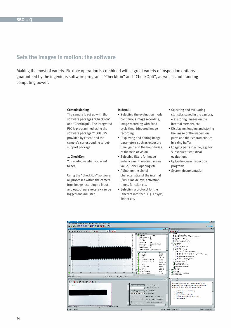
1. CheckKonYou configure what you want to see!
Using the “CheckKon” software, all processes within the camera – from image recording to input and output parameters – can be logged and adjusted.
In detail:• Selecting the evaluation mode:
continuous image recording, image recording with fixed cycle time, triggered image recording
• Displaying and editing image parameters such as exposure time, gain and the boundaries of the field of vision
• Selecting filters for image enhancement: median, mean value, Sobel, opening etc.
• Adjusting the signal characteristics of the internal I/Os: time delays, activation times, function etc.
• Selecting a protocol for the Ethernet interface: e.g. EasyIP, Telnet etc.
• Selecting and evaluating statistics saved in the camera, e.g. storing images on the internal memory, etc.
• Displaying, logging and storing the image of the inspection parts and their characteristics in a ring buffer
• Logging parts in a file, e.g. for subsequent statistical evaluations
• Uploading new inspection programs
• System documentation
SBO...-Q

17
2. CheckOpti The camera inspects precisely what’s important!
Simple to define, simple toadjust and simulate on the PC. Inspection programs are set up with the software package CheckOpti:• Various sample parts have to
be positioned in front of the camera under the most realistic conditions possible and recorded on the PC. This provides the basis for defining the features to be inspected. These features are selected from a list and moved to the position to be checked on the sample part by dragging and dropping.
• A total of 256 features can be defined.
• Before the inspection program is used at the target device, the inspection features can be evaluated and optimised on the PC – with any number of parts.
• The software provides the option of summarising the inspection results into data packets and making them available to a master controller.
• The inspection program can then be uploaded to one of the camera’s 256 memory locations.
• CheckOpti works on a variety of images. The tolerances within which an inspection feature can be deemed good are taken from the sample parts. And thus the user only specifies what should actually be checked and the tolerances are based on the recorded images. The tolerances can of course be changed manually at a later date.
Inspection functions: See function selection on page 18.
SBO...-Q

18
The SBO...-Q is highly flexible thanks to the many inspection programs and functions it’s capable of running. Take a close look: intelligent compact vision systems SBO...-Q from Festo are equipped with numerous tools with which you can check almost anything. The end result is a product with one of the best price/performance ratios on the market.
Great functionality at a small price – available tools
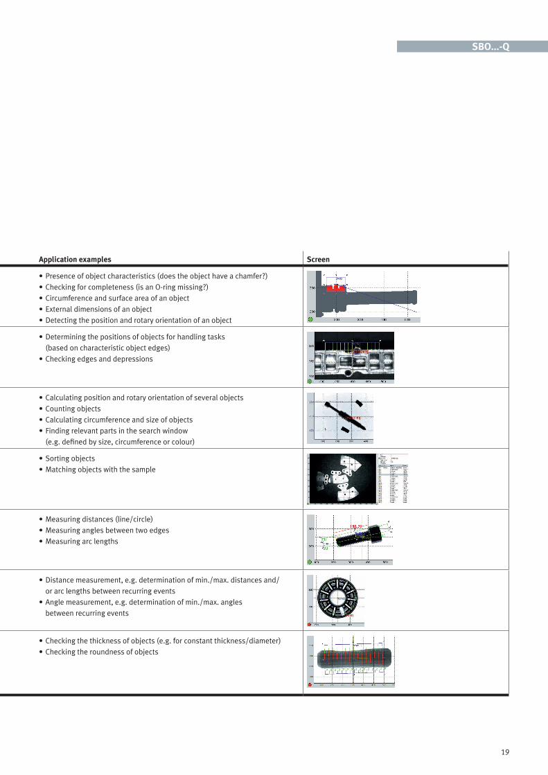
Tool Description Application examples Screen
ROI Area in which all pixels are seen as a cohesive object. Characteristics such as key coordinates, dimensions, circumference and surface area can be calculated for this area.
• Presence of object characteristics (does the object have a chamfer?)• Checking for completeness (is an O-ring missing?)• Circumference and surface area of an object • External dimensions of an object• Detecting the position and rotary orientation of an object
Circle and edge finder Tools for determining least-square circles and least-square lines of object edges and the associated quality characteristics. Outlier points are removed by statistical methods.
• Determining the positions of objects for handling tasks (based on characteristic object edges)
• Checking edges and depressions
Blob finder The tool looks for adjacent pixels which lie within the previously selected brightness or colour range. These pixel clouds constitute individual objects. The objects can be counted, and individual characteristics can be calculated for up to 16 objects.
• Calculating position and rotary orientation of several objects• Counting objects • Calculating circumference and size of objects• Finding relevant parts in the search window
(e.g. defined by size, circumference or colour)
Pattern matching Tool for detecting characteristics of previously taught-in samples. Up to 4 samples can be taught in per tool. These are then searched for regardless of their rotary orientation and position within the tool area. The camera detects them even if they partially touch each other or are partially covered.
• Sorting objects• Matching objects with the sample
Simple measurement (normal or subpixel precision)
A search along a search line or circle for transitions between the background and the part, or for relevant changes in brightness. Detected transitions are numbered automatically. Two points can be used for each measurement.
• Measuring distances (line/circle)• Measuring angles between two edges• Measuring arc lengths
Multiple measurement (normal or subpixel precision)
A search along a search line or circle for transitions between the background and the part, or for relevant changes in brightness. Transition types (e.g. light to dark) are ascertained and establish the measurements in pairs.
• Distance measurement, e.g. determination of min./max. distances and/ or arc lengths between recurring events
• Angle measurement, e.g. determination of min./max. angles between recurring events
Ray tool (normal or subpixel precision)
A search along parallel or star-shaped search lines (in any required number) for transitions between the background and the part, or for relevant changes in brightness. Detected points are numbered and a simple measurement is performed n times between the respective start/end points.
• Checking the thickness of objects (e.g. for constant thickness/diameter)• Checking the roundness of objects
SBO...-Q
19
Tool Description Application examples Screen
ROI Area in which all pixels are seen as a cohesive object. Characteristics such as key coordinates, dimensions, circumference and surface area can be calculated for this area.
• Presence of object characteristics (does the object have a chamfer?)• Checking for completeness (is an O-ring missing?)• Circumference and surface area of an object • External dimensions of an object• Detecting the position and rotary orientation of an object
Circle and edge finder Tools for determining least-square circles and least-square lines of object edges and the associated quality characteristics. Outlier points are removed by statistical methods.
• Determining the positions of objects for handling tasks (based on characteristic object edges)
• Checking edges and depressions
Blob finder The tool looks for adjacent pixels which lie within the previously selected brightness or colour range. These pixel clouds constitute individual objects. The objects can be counted, and individual characteristics can be calculated for up to 16 objects.
• Calculating position and rotary orientation of several objects• Counting objects • Calculating circumference and size of objects• Finding relevant parts in the search window
(e.g. defined by size, circumference or colour)
Pattern matching Tool for detecting characteristics of previously taught-in samples. Up to 4 samples can be taught in per tool. These are then searched for regardless of their rotary orientation and position within the tool area. The camera detects them even if they partially touch each other or are partially covered.
• Sorting objects• Matching objects with the sample
Simple measurement (normal or subpixel precision)
A search along a search line or circle for transitions between the background and the part, or for relevant changes in brightness. Detected transitions are numbered automatically. Two points can be used for each measurement.
• Measuring distances (line/circle)• Measuring angles between two edges• Measuring arc lengths
Multiple measurement (normal or subpixel precision)
A search along a search line or circle for transitions between the background and the part, or for relevant changes in brightness. Transition types (e.g. light to dark) are ascertained and establish the measurements in pairs.
• Distance measurement, e.g. determination of min./max. distances and/ or arc lengths between recurring events
• Angle measurement, e.g. determination of min./max. angles between recurring events
Ray tool (normal or subpixel precision)
A search along parallel or star-shaped search lines (in any required number) for transitions between the background and the part, or for relevant changes in brightness. Detected points are numbered and a simple measurement is performed n times between the respective start/end points.
• Checking the thickness of objects (e.g. for constant thickness/diameter)• Checking the roundness of objects
SBO...-Q
20
Tool Description Application examples Screen
Brightness inspection The brightness or contrast of the pixels can be determined in a freely definable area within the image.
• Brightness inspection• Checking for completeness
Colour inspection The colour of the pixels in the RGB, HSV and YUV colour spectra can be determined in a freely definable area within the image.
• Colour inspection (e.g. right colour in the right place)
Coordinate transformation Nonlinear transformation of viewing coordinates into global coordinates. • Computational elimination of perspective and optical distortion from position results (for handling tasks)
Data matrix code reader Tool for reading 2D codes (QR, PDF417 and ECC200). Furthermore, the quality of each scanned ECC200 code can be determined in accordance with ISO 15415 guidelines.
• Reading data matrix codes• Checking the quality of data matrix codes
Barcode reader Tool for reading 1D codes (barcodes) • Reading bar codes
Text recognition (OCR) Tool for reading optical characters. • Reading batch numbers• Reading expiry dates• Reading dot-peened production dates
SBO...-Q

21
Tool Description Application examples Screen
Brightness inspection The brightness or contrast of the pixels can be determined in a freely definable area within the image.
• Brightness inspection• Checking for completeness
Colour inspection The colour of the pixels in the RGB, HSV and YUV colour spectra can be determined in a freely definable area within the image.
• Colour inspection (e.g. right colour in the right place)
Coordinate transformation Nonlinear transformation of viewing coordinates into global coordinates. • Computational elimination of perspective and optical distortion from position results (for handling tasks)
Data matrix code reader Tool for reading 2D codes (QR, PDF417 and ECC200). Furthermore, the quality of each scanned ECC200 code can be determined in accordance with ISO 15415 guidelines.
• Reading data matrix codes• Checking the quality of data matrix codes
Barcode reader Tool for reading 1D codes (barcodes) • Reading bar codes
Text recognition (OCR) Tool for reading optical characters. • Reading batch numbers• Reading expiry dates• Reading dot-peened production dates
SBO...-Q

22
Control via the camera: integrated CODESYS makes systems leaner and processes more stable. It provides decentralised intelligence with suitable but fewer interfaces, and less wiring.
Unique: camera with integrated PLC
More functionsCODESYS embedded is included in the camera, which can be programmed with all standard programming languages in accordance with IEC 61131-3 (KOP, FUP, ST, AWL, SFC).
This opens up a host of opportunities:• Linking the calculation results
within a camera network – for example, as a master system a camera can read the calcula-tion results of another camera, link them with its own and take action on this basis.
• Complex inspection sequences including switching between inspection programs and comparison of results. And thus there’s no need to learn an extra script language, as is the case with many other cameras on the market.
• Small, autonomous production areas can be controlled directly by the camera, thus reducing complexity and increasing system availability.
• Direct activation of servo controllers via CANopen, e.g. for precision positioning of axes or activation of handling units for flexible gripping of
components – no additional controller required!
• The integrated PLC can exchange data with the “Quality inspection” software application via a function block.
SBO...-Q
23
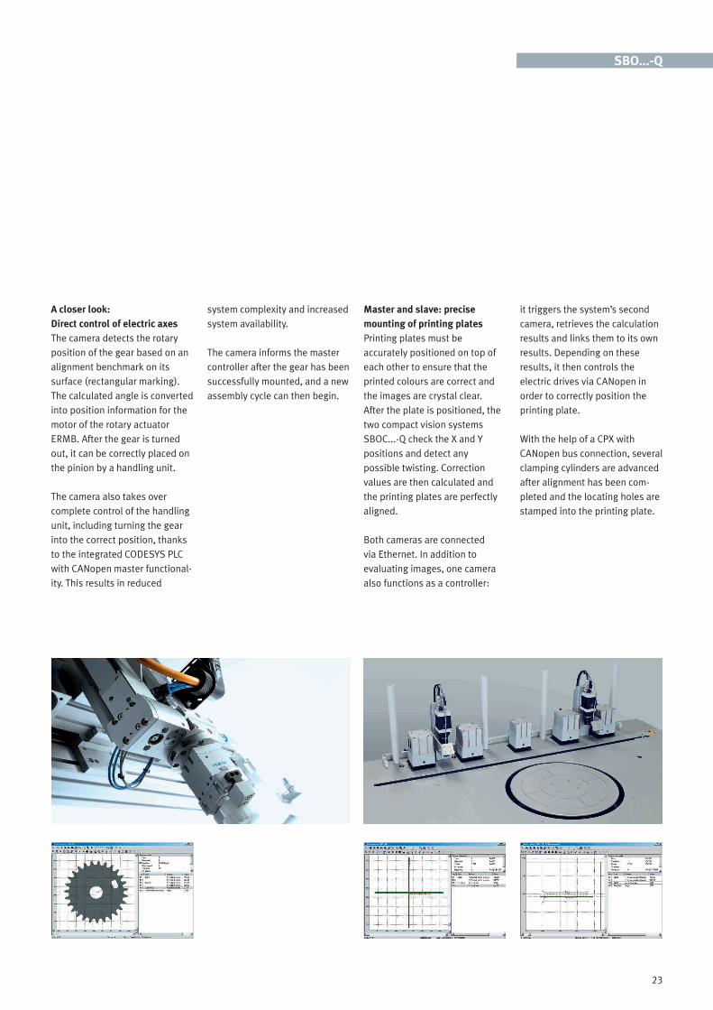
A closer look:Direct control of electric axesThe camera detects the rotary position of the gear based on an alignment benchmark on its surface (rectangular marking). The calculated angle is converted into position information for the motor of the rotary actuator ERMB. After the gear is turned out, it can be correctly placed on the pinion by a handling unit.
The camera also takes over complete control of the handling unit, including turning the gear into the correct position, thanks to the integrated CODESYS PLC with CANopen master functional-ity. This results in reduced
system complexity and increased system availability.
The camera informs the master controller after the gear has been successfully mounted, and a new assembly cycle can then begin.
Master and slave: precise mounting of printing platesPrinting plates must be accurately positioned on top of each other to ensure that the printed colours are correct and the images are crystal clear. After the plate is positioned, the two compact vision systems SBOC...-Q check the X and Y positions and detect any possible twisting. Correction values are then calculated and the printing plates are perfectly aligned.
Both cameras are connected via Ethernet. In addition to evaluating images, one camera also functions as a controller:
it triggers the system’s second camera, retrieves the calculation results and links them to its own results. Depending on these results, it then controls the electric drives via CANopen in order to correctly position the printing plate.
With the help of a CPX with CANopen bus connection, several clamping cylinders are advanced after alignment has been com-pleted and the locating holes are stamped into the printing plate.
SBO...-Q
24
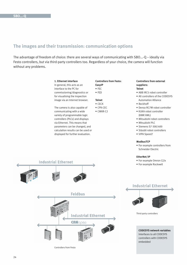
The advantage of freedom of choice: there are several ways of communicating with SBO...-Q – ideally via Festo controllers, but via third-party controllers too. Regardless of your choice, the camera will function without any problems.
The images and their transmission: communication options
1. Ethernet interfaceIn general, this acts as an interface to the PC for commissioning/diagnostics or for visualising the inspection image via an Internet browser.
The camera is also capable of communicating with a wide variety of programmable logic controllers (PLCs) and displays via Ethernet. This means that parameters can be changed, and calculation results can be used or displayed for further evaluation.
Controllers from Festo:EasyIP• FEC • FED
Telnet • CECX• CPX-CEC• CMXR-C2
Controllers from external suppliers:Telnet • ABB IRC5 robot controller• All controllers of the CODESYS
Automation Alliance• Beckhoff • Denso RC7M robot controller • KUKA robot controller
(KMR XML)• Mitsubishi robot controllers • Mitsubishi PLC• Siemens S7-300/400• Stäubli robot controllers• VIPA Speed7
ModbusTCP• For example controllers from
Schneider Electric
EtherNet/IP • For example Omron CJ2x• For example Rockwell
SBO...-Q
Controllers from Festo
Third-party controllers
CODESYS network variables Interfaces to all CODESYS controllers with CODESYS embedded

25
2. CAN interfaceComponents from Festo: used as CPI module With this setting, the camera corresponds to a CPI module with 16 inputs and 16 outputs.
In combination with a CPX-CP module and a CPX fieldbus node, for example, the camera can be accessed via Profibus DP, Interbus, DeviceNet, CANopen and CC-Link.
I/O expansionI/O expansion of the camera with the modules CP-A04-M12-CL and CP-E08-M12-CL: • Output and input module can
be written to and read via the inspection program
Or can be used as: • Output module for indicating
part types• Input module for binary
preselection of the inspection program
Components from Festo or other suppliers used as CANopen mastersCANopen master functionality results from combination with CODESYS embedded.
3. Internal 24 V I/O24 V digital inputs (2)• Triggering of the camera or
input with freely definable function (via inspection program or CODESYS)
• Error acknowledgment/accept-ance of extended inputs or input with freely definable function (via inspection program or CODESYS)
SBO...-Q
24 V digital outputs (3)• Output 0 parameterisable
(ready for operation, good part, reject part, correctly oriented, incorrectly oriented, error, warning, controlled by CODESYS, controlled by inspection program)
• Output 1 parameterisable (good part, reject part, correctly oriented, incorrectly oriented, error, warning, controlled by CODESYS, controlled by inspection program)
• Output 2 parameterisable (good part, reject part, correctly oriented, incorrectly oriented, error, warning, external lighting, controlled by CODESYS, controlled by inspection program)
I/O expansion
CANopen master
CPI module

26
Vision sensors SBSI Code reader SBSI-B Object sensor SBSI-Q
SBSI-B-R3B-F6-x SBSI-B-R3B-F12-x SBSI-Q-R3B-F6-x SBSI-Q-R3B-F12-x
Optical system
Sensor resolution 736 x 480 pixels (wide VGA), monochrome
Focal length 6 mm 12 mm 6 mm 12 mm
Min. field of vision Min. 5 x 4 mm Min. 8 x 6 mm Min. 5 x 4 mm Min. 8 x 6 mm
Min. working distance 6 mm 30 mm 6 mm 30 mm
Integrated lighting White, red, infrared White, infrared
Mechanical system
Dimensions 45 x 45 x 76.7 mm
Degree of protection IP67
Information on cover materials Fibreglass reinforced ABS
Information on housing materials Anodised aluminium
Ambient temperature 0 ... 50 °C
Weight 160 g
Resistance to shocks and vibration
EN60947-5-2
General
Max. number of jobs 8
Max. number of detectors (per job)
2 32
Detectors 1D barcodes: EAN, UPC, RSS, 2/5 Interleaved, 2/5 Industrial, Code 39, Code 93, Code 128, GS1, Pharmacode, Codabar;2D codes: ECC200, QR Code, PDF 417
Position tracking via contour, comparison with sample, contour comparison, contrast, brightness, greyscale value threshold
Cycle time Typically 30 ms for 1D barcode and 40 ms for 2D code Typically 30 ms for position tracking, 20 ms for pattern matching, 30 ms for contour comparison, 4 ms for contrast, 2 ms for brightness and 4 ms for grey value threshold
Electronics
Max. output current 50 mA (1x power output, 100 mA)
Nominal DC operating voltage 24 V
Current consumption with load-free outputs
200 mA
Max. current consumption 550 mA
Input resistance > 20 K
Switching output PNP/NPN, switchable
Switching input PNP/NPN, high > UB-1 V, low < 3 V
Communication interfaces
Serial interface RS-232, RS-422 –
Ethernet Ethernet/IP, Ethernet TCP/IP, FTP, SMB
Inputs/outputs 2 inputs, 4 outputs, 2 selectable inputs/outputs
Vision sensors and compact vision systems are used in a variety of applications. With Festo the choice is yours: there’s a well-matched, efficient solution for almost any requirement. The decision is made easy, because all you have to do is select a product based on the characteristics, functions and features you have defined.
Vision sensors SBSI and compact vision systems SBO...-Q at a glance
27
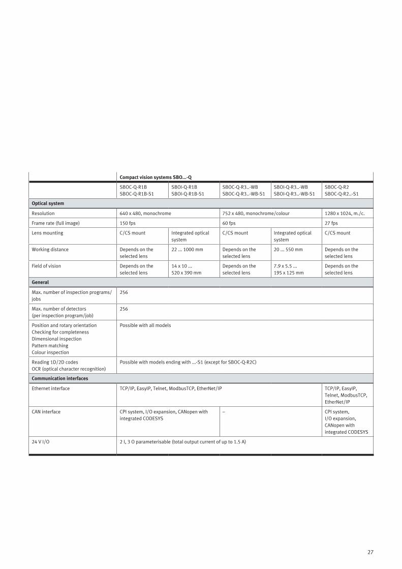
Compact vision systems SBO...-Q
SBOC-Q-R1BSBOC-Q-R1B-S1
SBOI-Q-R1BSBOI-Q-R1B-S1
SBOC-Q-R3..-WBSBOC-Q-R3..-WB-S1
SBOI-Q-R3..-WBSBOI-Q-R3..-WB-S1
SBOC-Q-R2 SBOC-Q-R2..-S1
Optical system
Resolution 640 x 480, monochrome 752 x 480, monochrome/colour 1280 x 1024, m./c.
Frame rate (full image) 150 fps 60 fps 27 fps
Lens mounting C/CS mount Integrated optical system
C/CS mount Integrated optical system
C/CS mount
Working distance Depends on the selected lens
22 ... 1000 mm Depends on the selected lens
20 ... 550 mm Depends on the selected lens
Field of vision Depends on the selected lens
14 x 10 ... 520 x 390 mm
Depends on the selected lens
7.9 x 5.5 ... 195 x 125 mm
Depends on the selected lens
General
Max. number of inspection programs/jobs
256
Max. number of detectors (per inspection program/job)
256
Position and rotary orientationChecking for completenessDimensional inspectionPattern matchingColour inspection
Possible with all models
Reading 1D/2D codes OCR (optical character recognition)
Possible with models ending with ...-S1 (except for SBOC-Q-R2C)
Communication interfaces
Ethernet interface TCP/IP, EasyIP, Telnet, ModbusTCP, EtherNet/IP TCP/IP, EasyIP, Telnet, ModbusTCP, EtherNet/IP
CAN interface CPI system, I/O expansion, CANopen with integrated CODESYS
– CPI system, I/O expansion, CANopen with integrated CODESYS
24 V I/O 2 I, 3 O parameterisable (total output current of up to 1.5 A)

Productivity
Maximum productivity is a question of ambitionDo you share this attitude? We will be glad to help you achieve this goal – through our four outstanding qualities: • Security • Efficiency • Simplicity • Competency
We are the engineers of productivity.
Discover new dimensions for your company: www.festo.com/whyfesto
1351
19 e
n 20
14/1
0 –
Erro
rs a
nd o
mis
sion
s ex
cept
ed