Embed Size (px)
Citation preview

Author: Philippe MazouerAssistants supervisors: Alejandra García Rojas & Mario GutiérrezProfessor: Daniel Thalmann
January 10, 2008
Visual Programming of 3DScenes
Semester Project

Contents
1 Introduction 31.1 Overview . . . . . . . . . . . . . . . . . . . . . . . . . . . . . . . 31.2 Semantic Information . . . . . . . . . . . . . . . . . . . . . . . . 31.3 Visual Programming . . . . . . . . . . . . . . . . . . . . . . . . . 51.4 Goals of the project . . . . . . . . . . . . . . . . . . . . . . . . . 6
2 OWL Information Extraction 72.1 Jena Parser . . . . . . . . . . . . . . . . . . . . . . . . . . . . . . 9
3 2D Representation / Data Manipulation 113.1 Entities Representation . . . . . . . . . . . . . . . . . . . . . . . 113.2 Visual Libraries . . . . . . . . . . . . . . . . . . . . . . . . . . . . 123.3 3D Positioning . . . . . . . . . . . . . . . . . . . . . . . . . . . . 123.4 Virtual Human Features . . . . . . . . . . . . . . . . . . . . . . . 13
3.4.1 �Look at� action . . . . . . . . . . . . . . . . . . . . . . . 133.4.2 Key Frame Animation . . . . . . . . . . . . . . . . . . . . 14
4 3D Scene 154.1 Java and C++ Sockets . . . . . . . . . . . . . . . . . . . . . . . . 154.2 Communication Protocol . . . . . . . . . . . . . . . . . . . . . . . 16
5 Evaluation and Discussion 18
6 Conclusion & Future Work 196.1 Future Work . . . . . . . . . . . . . . . . . . . . . . . . . . . . . 19
6.1.1 Taking Time into Account . . . . . . . . . . . . . . . . . . 196.1.2 Walking Engine . . . . . . . . . . . . . . . . . . . . . . . . 206.1.3 Collision Detection . . . . . . . . . . . . . . . . . . . . . . 20
6.2 Conclusion . . . . . . . . . . . . . . . . . . . . . . . . . . . . . . 21
7 References 22
2

1 Introduction
1.1 Overview
Creating a 3D scene or even composing a 3D scenario might not be the easiestand fastest thing to do. You will need to work with a graphical API (Open GL,Direct X, etc.) or learn to use a 3D Engine that may ease the work. But that'snot the hardest part! Unless the scene is empty, you will need to work withentities such as houses, plants, chairs or humans. They will need to be placedexactly where you want them to be and in the case of virtual �living� entities,doing exactly what you want them to do. Of course, such a task is far fromimpossible but may use a lot of time and resources.
This is where this project starts: with some a priori knowledge of semanticinformation concerning our virtual entities and using a visual programmingparadigm, we will try to develop an application allowing anyone to setup easilyany kind of 3D scene or scenario.
1.2 Semantic Information
One thing I need to explain �rst is this knowledge of the virtual entities. Whatis it and why is it needed in this application ?
In order to answer the �rst part of the question, allow me to use an example:when you want to add a human in a 3D world, it will most likely consist of acertain amount of data. Maybe a �le, describing the geometry of the person ora certain structure de�ned to represent triangles or points in space where theperson will be. This information is necessary for the computer to display anykind of shape and it will also be a part of our a priori knowledge. But whatabout the name of the person, what about his or her gender, his or her weight ?We would never talk about a pair of shoes saying the resolution of the laces isreally high or the texture mapped into the outside is from a bmp �le.This kind of information is what we would use to describe a person. They arealso important to complement the representation of the virtual character (we willsee later how the application make use of such information to match animationswith individual personality) , but they're not included in the geometry. That'swhy they need to be incorporated in a kind of database. We will therefore use anontology (knowledge representation) for our entities and also see shortly whatis present in this ontology as well as how it is encoded.
Now, for the second part of the question, the answer lies in our motivation tomake the process of 3D creation easier. People can work much faster with thiskind of high level representation of information than with matrices or trian-gles. If the application provides a good interaction between those parameters(height, gender, position, etc.), anyone will be able to easily create a living 3Denvironment.
Finally, concerning the encoding of the information, the choice was made before-hand to use the OWL1 ontology language. The Ontology is a recent standardizedway of representing information. It is used by the semantic web due to facilityto decentralize information. Ontologies provides a higher structure level than
1http://www.w3.org/TR/owl-features/
3

relational databases, as one can de�ne concepts with properties, relationshipsbetween concepts and restriction rules (axioms). The Ontology Web Language(OWL) is one of many ontology languages available, based on earlier languagesuch as OIL, DAMN or DAMN+OIL and was build on top of RDF2(a generalmethod of modeling information) with a larger vocabulary and stronger syntax.This �machine-interpretable� language will carry the ontology of all our entities.
2http://en.wikipedia.org/wiki/Resource_Description_Framework
4

1.3 Visual Programming
Another really important model our application will use is Visual Programming.This paradigm is used when the user of an application, instead of specifying el-ements textually, will manipulate them graphically. It will help us again totremendously simplify the task of creating a 3D world. For creating 3D envi-ronments, it is commonly necessary to have a lot of programming knowledge inC/C++ or Java for example. Moreover, someone would need to have basis ofcomputer graphics. We would like to allow non experts to be able to create a3D scene thanks to the integration of this paradigm. Instead of typing a fewlines of code in order to load an object into the scene, you will simply drag anddrop a box representing the object in the application. Instead of using pointersand variables to create a link between two entities, you will simply create anarrow with the mouse in between those two entities.Everything will be done in order to provide the most easy-to-use interface whileallowing the user as much freedom as possible in the creation process.
This approach of using �boxes and arrows� is not new and is also widely used forall kind of creation processes. One example which is used to process graphicaldata is Quartz Composer from Apple3. The interface which is displayed belowwill be the main model for our interface.
Figure 1: Quartz Composer
There exists softwares based on this paradigm to compose music, draw electricallogic schematics or even develop web applications.
3http://en.wikipedia.org/wiki/Quartz_Composer
5

1.4 Goals of the project
In this project we will provide an application that allows a real time con�gura-tion of a 3D environment using semantic information and a visual programmingparadigm. The next three chapters will each be dedicated to a certain sectionof the application: we will discuss the choice of technology for the section, theimplementation process and the design decisions.
The reason behind this separation is that the process of creation is also split inthree: you will �rst use an ontology �le which will act as a database for all theobjects on the scene then you will load in a 3D scene these objects and �nallymanipulate/con�gure them in a 3D world.
Figure 2: Application segments
At the end we will also go over a few features that might be added to the ap-plication in order to improve the creation process or allow �ner control over thescene. We will then discuss the result obtained with this application comparedto a classical approach since we're now inclined to use both.
6

2 OWL Information Extraction
The �rst step of our application development is getting the information fromthe ontology �le. Everything concerning the entities is contained in an OWL�le so the task here was to extract this information and store it in order to havea quick and easy access for the upper sections of the application.We're using a simpli�ed version of the Virtual Human Ontology de�ned in [3].This project led to the creation of an ontology specially de�ned for VirtualHumans in order to make them more active and understandable for both humansand machines.Only a few modi�cations occurred during the implementations to add objectsin the OWL �le.Here is the graphical representation of an object :
Figure 3: Object Ontology
An object only has a few parameters to go with it : position in space, orientationand geometry. We could eventually create di�erent classes of objects (housing,garment, food, etc.) in order to have more precised parameters but for simplicitywe will consider only this model of object.
Now, since it would be uninteresting only to haveobjects in our scene and be-cause I insisted on the importance of semantic information, I need to presentthe interesting part of the OWL �le which contains the description of a VirtualHuman :
7

Figure 4: Virtual Human Ontology
There, we clearly have a more complex structure. I will not go into details forevery class or link between classes (it is not the purpose of this section) but I willjust highlight some of the parameters that are interesting for our application :
• First of all, I mentioned brie�y the possibility to create 3D scenarios. Forthis to happen, we will most likely need movement and we will be able toadd animation to our Virtual Human thanks to the �Animation� property.
• Also, the Virtual Human is not only described by a name, position andorientation but also morphological and emotional parameters. These pa-rameters however will not be editable. (Changing the gender will haveabsolutely no impact on the geometry, for example.) But they will helpus to organize or sort the data in an e�cient way.
So, now that we have the structure of our ontology clearly de�ned, we will needto create a somewhat similar structure for our application, in order to store theinformation of the database. The way we're going to proceed is that a classwill be created for both our main entities (virtual human and objects) and eachelement of the hierarchy above will be either represented as a parameter or as
8

a class. Links will also be established between classes, so we can retrieve aparticular information regarding an individual.
2.1 Jena Parser
We will now see how this parser was implemented. The programming languagechosen to develop the application is Java. (However, for the last part of theproject, C++ was used in order to support the 3D Engine but we'll get intothat later) There is a few reason behind this choice, but the main one would bebecause as far as we know, all development for ontologies are in Java. There isnothing done to work in other languages like C++.
Therefore, In order to accomplish the information extraction, I used the Jenaframework4 for Java. Thanks to the API, understanding how the libraries in-teract with the owl ontology was easier and once I knew how to ask the �le theinformation I needed to extract, the rest was simply to create an array of classesfor each parameters and entities.
Here is a quick example showing how to extract the �Animation� class from theontology:
1. First you need to regroup all information you know about the class: Wemust know its name (�Animation� in this case) as well as the name of itsproperties. Here we're having two kinds of properties : simple variablessuch as �hasFile� and �hasDurationInSeconds�, and classes: �hasCategory�,�describesEmotion� and �hasMorphologicalDescription�.
2. When we go through the �le, we must catch the classes who are named�Animation�. Once in this state, we create a new Java class Animation(the one we de�ned, not the one from the ontology) and we start de�ningthe parameters. Simple variables are obtained by a �getProperty� functionwith the name of the property and for the more complex one, we will goin a loop looking, for example, at the emotions the animation describes.But, we won't go down in the hierarchy yet! We only keep the name ofthe emotion(s) that interest(s) us.There is also more thing you could do in this step, like looking if thestructure of the ontology is respected by checking if the cardinality of alink is correct, or if a reference to a �le is incorrect because the �le doesn'texist, etc.
3. When all classes are parsed, we can start creating the link between classesand not only keep the name as a reference.
We could be tempted to create the link present in the graph during the parsing,but since the individuals are not parsed orderly from top to bottom or bottomto top, we have to wait until every instance of classes is parsed and then we cancheck and create the links.There is of course some simpli�cation to be done: it is useless to create a classfor each motion category (in the Virtual Human ontology). In this case, a simpleboolean in the MotionCategory class for each �is-a� relation is su�cient.
4http://jena.sourceforge.net/
9

One last thing needed was to make both the object and virtual human classescloneable in order to allow multiple instances of such classes in the scene. Let'ssuppose that in our OWL �le, we have a stone. If we want to build a wall withthe stone object, each stone will have di�erent parameters. That's why we needa bitwise copy of the object and not just a shallow one.
10

3 2D Representation / Data Manipulation
We now reach the core part of the application, the graphical user interface. Thissection will cover how the individuals are displayed and how the user will beallowed to manipulate them. Since we will de�ne a short Visual Programming�language�, every manipulation will be graphical and a few rules will be set inorder to deny faulty actions.
You may say that a picture is worth a thousand words, so before entering intodetails for each component, here is a quick snapshot of the interface :
Figure 5: Visual Programming GUI
The screen is already �lled with a few objects and a random scene, but everypart of the interface will be explained in the following chapters.
3.1 Entities Representation
First thing �rst, we need to inform the user of the di�erent individuals presentin the database we just parsed. For this simple step, displaying the name of theentity correctly sorted in his class is su�cient. (We assume that the name isrelevant enough for the user to di�erentiate two entities)The result is showed in the �rst red square in �gure 4: A simple JTree did thetrick.
11

3.2 Visual Libraries
Simply showing entities would not be enough. We need to add, remove and playwith those instances. To achieve this goal I was asked to look for a library thatmight facilitate the integration of visual elements in the interface. My choicewent for the NetBeans Visual Library5 which o�ers support for graph-orientedmodeling. The result can be seen on the second red square of the �gure 4.Entities are represented in blue squares and can be freely moved around in thescene with the mouse. In order to lighten the representation, only a few basicparameters are displayed on those squares : name, class and geometry. Thearrows and the other window inside the scene will be discussed in the followingchapters.
The way the scene works is as follow: we have a main component, the Graph-Scene on top of which we add �Widget6 Layers�. Each of those layers will haveits own purpose: adding widgets, making connections, de�ning the background,moving widgets, etc.You might have guessed by now, the entities are widgets. Actually, the bluesquares are a composition of a node widget (the top) and pin widgets (proper-ties). Everytime an entity is added to the scene, all the necessary data belongingto the entity is copied and placed into an array. You can have multiple instancesof the same object, as previously mentioned; only the name will change.
I would be lying if I say that integrating the so called �GraphScene� in theinterface and insuring that the scene would only allow certain manipulationswas easy, mainly due to the fact that not so many documentation and complexexamples exist, but by the process of trials and errors, I'm proud to have reacha satisfactory level of interaction for the task at hand.
3.3 3D Positioning
Everything is well in the scene : we can now add and remove elements. Butthen, if we stop there we could only create a pile of object at the center of theworld. We need to add rotation and translation on all axis ! This way, we coverevery orientation or position possible for any arbitrary entity.
Actually, one thing I omitted in the previous chapter was that the translationon the ground (plane XZ) is already implemented without any other buttons orscrollbars. One feature was to generate a position on the plane correspondingto the position of the widget in the scene. This way of moving the entitieslike we were seeing the scene from above created a stronger link between the2D representation and the 3D representation which is more interesting becauseevery user can now more easily move a widget in the environment withoutlooking at the 3D world to con�rm its position.
For the rest of the controls, they appear on the bottom left of the screen.We have three buttons representing the three possible axis of rotation, witha scrollbar to indicate the degree of rotation. There's also a scrollbar for thevertical translation, since we already covered X and Z translations.
5http://graph.netbeans.org/6http://en.wikipedia.org/wiki/GUI_widget
12

Everytime a modi�cation is done on those parameters, the properties of theelement is changed instantaneously and the change is re�ected on the 3D world.(We will see how in the last part.)
3.4 Virtual Human Features
3.4.1 �Look at� action
Now that we've covered every possible position in 3D, we will shift our interestinto more speci�c features only applicable to virtual humans. The �rst one wewill talk about is the �look at� functionality. This feature was possible thanksto an already de�ned algorithm in the 3D engine. What was left to do is tomake the link between this 2D representation and what we see in 3D. As youcan see, the �look at� is represented by an arrow on the scene:
Figure 6: Look at
Actually, the right part of the picture is not exactly representative of the left
part, since the red_stone would be placed behind Brian, but it just to show how
the connection is made.
An arrow between two entities was the �rst graphical choice that came to mindin order to implement this functionality. It is probably how someone wouldquickly draw a person looking at something on paper. It is done thanks to the�connection layer� of the scene; the arrow itself is a widget. We just need tomake some veri�cations before the connection is established since it is only validbetween virtual humans and virtual humans and objects. The user only has tomaintain the control key while moving the mouse to create a connection likethis.
13

3.4.2 Key Frame Animation
The last feature implemented for the interface make signi�cantly more use of theontology of the virtual human. We talked about scenario and we've seen thata virtual human could possibly hold animations. That's why when you doubleclick on a virtual human, you will see a small window appear on the screen,with the name of the virtual human and a list of animations. These animationsare the one found in the OWL �le and they are �ltered speci�cally for thevirtual human in question. Let me explain why : in �gure 3 (the virtual humanontology), you can see that the virtual human has a morphological descriptionand the animation too! That's why, if they're not yet linked, we could check bothmorphological descriptions and allow only certain animations to be associatedto a particular person. We can be more or less strict, but in the case of thisapplication, we just made sure the gender is correct.
So, once you've associated one or more animations to a certain virtual humanand you closed the window, the �Play� button on the top right part of theapplication will become available. If you press the button, the interface willfreeze and the actors on the 3D part will play their animations until they aredone. There is no special timing edition possible here, every virtual human willplay his animation one after the other. We will discuss later what could beadded to allow a more precise control of these scenarios.
14

4 3D Scene
We �nally reached the last section of our application: the 3D world. So far, I'vementioned that the application would allow real-time con�guration of a 3D worldand that some modi�cations were re�ected in this world. The main part of theprogram is developed in Java but for this part, we're going to use the MVisio7
3D Engine created here at the Federal Polytechnical School of Lausanne. Sincethe MVisio SDK is based on C++ architecture, this last part will be developedin C++ as well and we're going to �nd a way for the two di�erent programs tocommunicate.Here is a picture showing the entire application :
Figure 7: Visual Programming application
We will focus our attention now on the �Visual Programming Viewer� runningthe MVisio engine.
4.1 Java and C++ Sockets
The �rst problem to solve was to establish communication. We have two di�er-ent programs running in parallel, and we need real-time synchronization. Forthis, I've chosen to implement TCP Sockets on both applications. Since all theinteraction with the user is done on the Java side and the C++ 3d world willonly be there to display the result, we're going to have one blocking8 Java tcpserver and one non-blocking C++ TCP client.
7http://vrlab.ep�.ch/~apeternier/mvisio/main.html8When a client or a server is in �blocking� mode, everytime he sends a message, he will
stop running until the message has been received on the other end. (Same thing when youreceive, you stop until a message is available)
15

This choice was also made to simplify the implementation: instead of creatingmultiple threads, we can keep the C++ application simple and it will period-ically check if there is a message waiting for it. If not, the application keepsrunning so that the user can navigate in the 3D world with his mouse and key-board. On the other end, the Java server will make sure his message got throughbefore letting the user continue his work. (I need to stress that the messages arevery small, so even if the user keeps making changes, there will be no hiccupsvisible)
4.2 Communication Protocol
In order to make the two application understand each other, I've created a fewmessage �types� corresponding to a speci�c action. Those messages will be sendeverytime a change occurred in the Java application. (Adding an object, movingit, adding a look at function, etc.)Here is the list of messages along with their utility:
Function Message
Quit the application 0Add object/human 1(o/v)-name-path-�le-orientation-posx-poszRemove object/human 2(o/v)-nameModify parameters 3o(o/v)-name-posx-posz-0
3y(o/v)-name-posy3r(x/y/z)(o/v)-name-angle
Add/Remove animation 4(a/r)-name-path-�lePlay the animation(s) 5Add/Remove a �look at� 6(a/r)-source-target
Table 1: Messages
There is a few remarks I need to make about this list. Concerning the �rstmessage (quit), it is part of a synchronization problem. We have two applicationsin one, so you don't want to launch or close twice the application while working.This is why the C++ application is launched at the same time as the Javaapplication and is closed the same way. (We can run a command to executethe application, but to close it, it's preferable to send a message telling theapplication to close instead of killing the application with another command.)Also, in order to avoid a synchronization nightmare, they both stay open whileyou work.You should be familiar with the rest of the functions since we discussed themin the last chapter. We can also notice that it's not necessary to send the wholeobject or human in the message: we only send what is necessary. When we loada human or an object, we only need his name, the name of the �le holding thegeometry and a position.Concerning the parameters modi�cation, we have one message for ground trans-lations (on the plane XZ), one for vertical translations and one for each rotation.There's also one last message to launch the animations (when you press play).
One more thing worth mentioning was a small di�culty that occurred duringthe implementation of a last feature in the program: the possibility to save a
16

scene and to reload it. Until then, the user was never fast enough to catch onwith the C++ application. What is implied here is that the C++ applicationalways has the time to process any message before another one is sent. (Unlessmaybe the horizontal translations when the user moves the widget around for along time, but losing one or two coordinates in the process is far from dramaticsince what is important is that the entity is placed where the widget is at theend.)But, when the load functionality was implemented, the Java application had torestore a whole scene as fast as possible, and sometimes one or two messages werediscarded because the C++ application was seeing two concatenated messagesand simply didn't care about the second one, resulting in an avalanche of errors.That's why I had to enforce the C++ client to send a message informing theJava server that he had done its work and he is now ready to receive a newmessage.
17
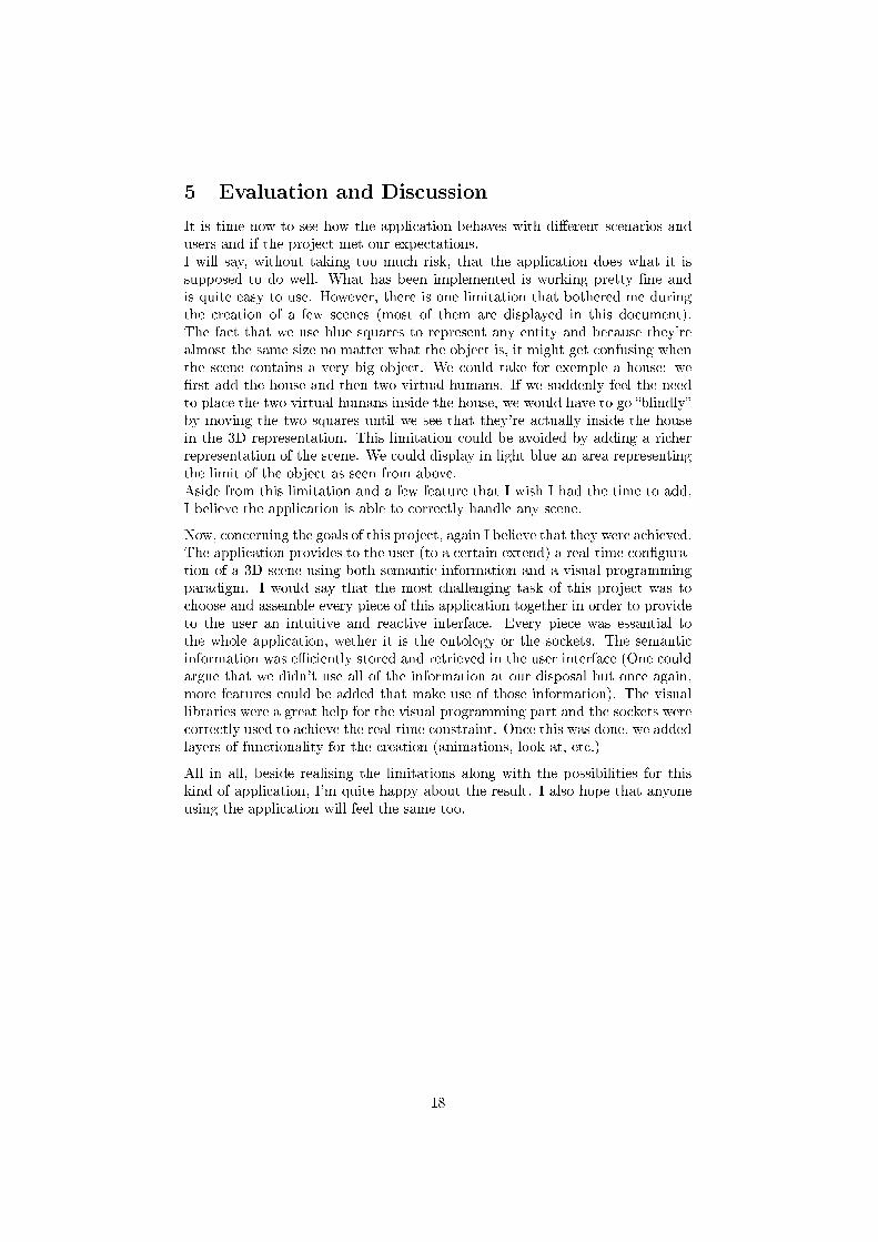
5 Evaluation and Discussion
It is time now to see how the application behaves with di�erent scenarios andusers and if the project met our expectations.I will say, without taking too much risk, that the application does what it issupposed to do well. What has been implemented is working pretty �ne andis quite easy to use. However, there is one limitation that bothered me duringthe creation of a few scenes (most of them are displayed in this document).The fact that we use blue squares to represent any entity and because they'realmost the same size no matter what the object is, it might get confusing whenthe scene contains a very big object. We could take for exemple a house: we�rst add the house and then two virtual humans. If we suddenly feel the needto place the two virtual humans inside the house, we would have to go �blindly�by moving the two squares until we see that they're actually inside the housein the 3D representation. This limitation could be avoided by adding a richerrepresentation of the scene. We could display in light blue an area representingthe limit of the object as seen from above.Aside from this limitation and a few feature that I wish I had the time to add,I believe the application is able to correctly handle any scene.
Now, concerning the goals of this project, again I believe that they were achieved.The application provides to the user (to a certain extend) a real-time con�gura-tion of a 3D scene using both semantic information and a visual programmingparadigm. I would say that the most challenging task of this project was tochoose and assemble every piece of this application together in order to provideto the user an intuitive and reactive interface. Every piece was essantial tothe whole application, wether it is the ontology or the sockets. The semanticinformation was e�ciently stored and retrieved in the user interface (One couldargue that we didn't use all of the information at our disposal but once again,more features could be added that make use of those information). The visuallibraries were a great help for the visual programming part and the sockets werecorrectly used to achieve the real-time constraint. Once this was done, we addedlayers of functionality for the creation (animations, look-at, etc.)
All in all, beside realising the limitations along with the possibilities for thiskind of application, I'm quite happy about the result. I also hope that anyoneusing the application will feel the same too.
18

6 Conclusion & Future Work
6.1 Future Work
Figure 8: Scene creation is all about possibilities
Now that we've seen every aspect of the application, I would like to quicklygo through a few ideas that weren't unfortunatly implemented for this project,mainly due to time limitation or missing resources. So far, what we've doneis creating all the necessary components in order to achieve the creation ofa 3D scene by the means of Visual Programming. We've also added a fewcontrols over our elements but achieving �total� control over the scene like aprogramming language would do would be time consuming and it wasn't thescope of the project to create an application like 3ds Max9.Without further ado, let's jump into a few ideas that could allow more complexscenes creation.
6.1.1 Taking Time into Account
One of the �rst thing that came to mind when we decided to use animationswas to control when they would start. The way the application works as of rightnow is that all animations are played one after the other, and when multiplepersons have animations, they would all start simultaneously. This, of coursedoesn't tolerate much freedom for a scenario. (Unless you would create an entireanimation for the whole scenario.)
9http://www.autodesk.com/3dsmax
19

The way this feature would have been added is the following: instead of manip-ulating time textually, a �timeline� bar would be displayed at the bottom of theinterface with one line for each person having an animation. Each animation�le associated to a person would be displayed as a rectangle showing when theanimation starts and when it �nishes. You would be able to move this animationrectangle in order to modify those parameters.
6.1.2 Walking Engine
Another thing that might surprise you when you start creating a scene with thisapplication is that the animations we talked about earlier are not locomotionanimations. (Even though in the ontology, there is space for locomotion anima-tions). So, our virtual humans are not nomads.Making them move around in the scene might not be as easy as it seems: �rst ofall, we need to choose how the user will input the parameters for the movement.We need to know where the virtual human will go and how. The speed alsoneeds to be taken into account and without already implemented algorithms ora walking engine, we would need to build the whole thing from the ground up.Speaking of ground, you wouldn't like it if suddenly the virtual human goesthrough a wall or �y in the sky. This issue will be discussed in the next section,but seeing how many seemingly little things need to be taken into account inorder to add movement, it was clear that this feature wasn't even considered asa feasible add-on to the application.
6.1.3 Collision Detection
The last thing I'm going to discuss is a more generic feature. Although so farwe've seen possible add-ons that would allow more freedom to the creation,this one is however limiting the possibilities. It might depend on what theuser is creating, but maybe he won't be too pleased about a virtual humanembedded in a wall or one that could walk through doors. This is actuallyallowed because there is no control over the position of the entities and the3D engine doesn't mind merging objects. What we could do is make sure twoentities don't collide with each other. This would not be too hard on objectsbut could lead to complicated calculations with virtual humans. The geometrycan be more complex and we have to be careful with animations!That's essentially why we let the user rectify manually the colliding errors thatmight occur in the scenario.
20

6.2 Conclusion
The joint use of semantic information and visual programming to help the cre-ation of 3D scenes showed promising results. I did �nd the process, althoughlimited, really fun and easy. It is somewhat faster to accommodate to a cer-tain visual programming paradigm than to learn a new programming languagealtogether. If the task to accomplish is in the boundaries of the application, Iwould not hesitate.
During these few weeks I also had the opportunity to touch di�erent technologiesand merge them. Whether in C++ or Java, I really enjoyed working to meetthe expectations of my supervisors and I would really like to thank them forallowing me to work on this project, helping and guiding me along the way.
Thank you very much for your time !
21

7 References
[1.] Visual programming language,
http://en.wikipedia.org/wiki/Visual_programming_language
[2.] M. Gutierrez, D. Thalmann, F. Vexo, Semantic Virtual Environments with Adaptive
Multimodal Interfaces, 11th International Conference on Multimedia Modelling, MMM2005,
Melbourne, Australia, 12-14 Jan 2005, pages 277-283
[3.] A. Garcia-Rojas, D. Thalmann, F. Vexo, L. Moccozet, N. Magnenat-Thalmann, M.
Mortara, M. Spagnuolo and M. Gutierrez, An Ontology of Virtual Humans: Incorporating
Semantics into Human Shapes, EWIMT'05, London, December 2005, pp. 7-14,
[4.] MVisio (Mental Vision)
http://vrlab.ep�.ch/~apeternier/mvisio/main.html
[5.] OWL Web Ontology Language Overview
http://www.w3.org/TR/owl-features/
[6.] Jena Semantic Web Framework
http://jena.sourceforge.net
[7.] Quart Composer
http://en.wikipedia.org/wiki/Quartz_Composer
[8.] Netbeans Visual Library tutorials and examples
http://graph.netbeans.org/
[9.] Autodesk 3ds Max
http://www.autodesk.com/3dsmax
22