Embed Size (px)
Citation preview
i
Visual Recognition of Hand Motion
THIS THESIS IS
PRESENTED TO THE
DEPARTMENT OF COMPUTER SCIENCE
FOR THE DEGREE OF
DOCTOR OF PHILOSOPHY
OF THE
UNIVERSITY OF WESTERN AUSTRALIA
By
Eun-Jung Holden
January 1997

ii
© Copyright 1997
by
Eun-Jung Holden

iii
Abstract
Hand gesture recognition is an active area of research in recent years, being
used in various applications from deaf sign recognition systems to human-
machine interaction applications. The gesture recognition process, in general,
may be divided into two stages: the motion sensing, which extracts useful data
from hand motion; and the classification process, which classifies the motion
sensing data as gestures. The existing vision-based gesture recognition
systems extract 2-D shape and trajectory descriptors from the visual input, and
classify them using various classification techniques from maximum likelihood
estimation to neural networks, finite state machines, Fuzzy Associative
Memory (FAM) or Hidden Markov Models (HMMs). This thesis presents the
framework of the vision-based Hand Motion Understanding (HMU) system
that recognises static and dynamic Australian Sign Language (Auslan) signs
by extracting and classifying 3-D hand configuration data from the visual
input. The HMU system is a pioneer gesture recognition system that uses a
combination of a 3-D hand tracker for motion sensing, and an adaptive fuzzy
expert system for classification.
The HMU 3-D hand tracker extracts 3-D hand configuration data that consists
of the 21 degrees-of-freedom parameters of the hand from the visual input of a
single viewpoint, with an aid of a colour coded glove. The tracker uses a
model-based motion tracking algorithm that makes incremental corrections to
the 3-D model parameters to re-configure the model to fit the hand posture
appearing in the images through the use of a Newton style optimisation

iv
technique. Finger occlusions are handled to a certain extent by recovering the
missing hand features in the images through the use of a prediction algorithm.
The HMU classifier, then, recognises the sequence of 3-D hand configuration
data as a sign by using an adaptive fuzzy expert system where the sign
knowledge are used as inference rules. The classification is performed in two
stages. Firstly, for each image, the classifier recognises Auslan basic hand
postures that categorise the Auslan signs like the alphabet in English.
Secondly, the sequence of Auslan basic hand postures that appear in the image
sequence is analysed and recognised as a sign. Both the posture and sign
recognition are performed by the same adaptive fuzzy inference engine.
The HMU rule base stores 22 Auslan basic hand postures, and 22 signs. For
evaluation, 44 motion sequences (2 for each of the 22 signs) are recorded.
Among them, 22 randomly chosen sequences (1 for each of the 22 signs) are
used for testing and the rest are used for training. The evaluation shows that
before training the HMU system correctly recognised 20 out of 22 signs. After
training, with the same test set, the HMU system recognised 21 signs correctly.
All of the failed cases did not produce any output. The evaluation has
successfully demonstrated the functionality of the combined use of a 3-D hand
tracker and an adaptive fuzzy expert for a vision-based sign language
recognition.

v
Preface
An attempt to build an automated sign language translator began with the
translation of English text into sign language using computer graphics. This
work has been published as a Master's thesis at the University of Western
Australia (Holden 1991), in the proceedings o f the 1992 ACM/SIGAPP
Symposium on Applied Computing (Holden & Roy 1992A), and in the Computer
Graphics Forum (Holden & Roy 1992B).
The research presented in this thesis deals with the reverse problem that
translates hand motion images into signs. Preliminary investigation on the
vision-based recognition of hand motion has been reported in the Department
of Computer Science Technical Report Series (Holden 1993).
The work on the adaptive fuzzy expert system that classifies 3-D hand motion
data into a sign has been published previously. The classifier was initially
tested with the data that was generated by a Power Glove and the result has
been published in the proceedings of the 1994 Western Australian Computer
Science Symposium (Holden et al. 1994). The classifier was also tested with
synthetic motion data. This experiment and the results have been published in
the proceedings of the IEEE International Conference on Neural Networks (Holden
et al. 1995). An extended paper on the work has been accepted in the
International Journal of Expert Systems (Holden et al. 1997).

vi
The research work on the 3-D hand tracker and the classification results using
real motion data is yet to be published.
The work described in these publications, and this thesis, is solely my own.

vii
Acknowledgments
The course of this thesis has turned out to be quite eventful due to the birth of
my first child. It has been a struggle to complete this thesis that had to be
achieved concurrently with the more important duties of a mother and a wife.
Thus this was only possible with the help and support of many people.
Firstly, I would like thank my supervisors, Associate Professor Robyn Owens,
and Professor Geoffrey Roy for their academic and moral support during the
course of this study. I thank Robyn especially for her incredible skills and
patience that went into the proof reading of this thesis, as well as her empathy
and understanding in having to juggle the roles of student, mother and wife.
Geoff has been my supervisor throughout my entire postgraduate studies. I
am always thankful for his enthusiasm for my work, and I have greatly
benefited from his positive encouragement at times of difficulty.
Secondly, in developing a hand tracker, I appreciated help from various
people who communicated with me through email. Brigitte Dorner from
Simon Fraser University in Canada was very helpful in providing me with her
tracker programs and thesis, and answering my questions. My tracker has
turned out to be quite different from hers, but her enthusiastic help has
provided an excellent start to the tracker development. Dr. David Lowe from
British Columbia University in Canada has also provided me with his general
tracking source code, and the module that solves normal equations has been

viii
used in my hand tracker. James Regh from Carnegie Mellon University,
U.S.A. was also helpful answering questions about his hand tracker.
Thirdly, I thank colleagues who provided support for this research. Jason
Birch deserves much thanks for sharing his in-depth knowledge of fuzzy logic
with me in many discussions. Bruce Mills has always made himself available
to explain various mathematical problems. Dr. Dorota Kieronska provided
valuable friendship and support throughout the study and I appreciated her
proof–reading a major part of this thesis. Lifang Gu shared invaluable
discussions on 3-D model-based tracking. Macintosh gurus, Jon Quinn and
Marcus Jager provided excellent technical support at the earlier part of this
project, and Shay Telfer for the later part. I thank the colleagues at the
Robotics and Vision lab who made working towards the completion of this
thesis so pleasant, and especially Rameri Salama for the occasional proof
reading.
Fourthly, I would like to sincerely thank Dr Chris Sauer who taught me the
ways of research with tremendous patience and graciousness, during my
honours undergraduate year. His encouragement has lead me to postgraduate
studies.
Lastly, I would like to thank my parents who taught me the value of learning,
my brother Jai-Seung for his loving support, and my husband David and
daughter Jacqui, for allowing their lives to be shared with a computer. I thank
God for his goodness.

ix
To my parents,
Major General and Mrs Chang, Keun-Hwan,
who sacrificed everything for my education.

x
Contents
Abstract....................................................................................................................... iii
Preface........................................................................................................................... v
Acknowledgments................................................................................................... vii
Contents........................................................................................................................ x
Abbreviations ........................................................................................................... xiv
Chapter 1: Introduction ............................................................................................ 1
1.1 Background ................................................................................................................................ 1
1.2 Recognition of Gestures ........................................................................................................... 3
1.3 The Approach ............................................................................................................................ 6
1.3.1 Motion Sensing Through a 3-D Hand Tracker..................................................... 9
1.3.2 Classification of a 3-D motion sequence ............................................................... 9
1.3.3 Platform.................................................................................................................... 10
1.4 Contributions ........................................................................................................................... 11
1.5 Layout of the Thesis ................................................................................................................ 12
Chapter 2: Literature Review................................................................................. 14
2.1 Chapter Overview................................................................................................................... 15
2.2 Human Perception of Biological Motion ............................................................................. 16
2.3 Hand Shape Recognition........................................................................................................ 18
2.4 Motion Understanding Using Two-Dimensional Information ........................................ 20
xi
2.5 Three-Dimensional Motion Understanding Using VR Technology ................................ 25
2.6 Three-Dimensional Motion Sensing Techniques................................................................ 26
2.6.1 Three-Dimensional Model-Based Hand Tracking............................................. 28
2.7 Summary .................................................................................................................................. 30
2.8 Introduction to the HMU System ......................................................................................... 31
Chapter 3: A Vision-Based Three-Dimensional Hand Tracker ...................... 34
3.1 Chapter Overview................................................................................................................... 36
3.2 Assumptions ............................................................................................................................ 39
3.2.1 The signing speed................................................................................................... 39
3.2.2 Features and Occlusions ........................................................................................ 40
3.3 The Hand Model ..................................................................................................................... 40
3.4 Colour Glove ............................................................................................................................ 45
3.5 Feature Measurement ............................................................................................................. 49
3.5.1 Colour segmentation .............................................................................................. 49
3.5.2 Marker Detection .................................................................................................... 52
3.5.3. Imposter or Missing Markers .............................................................................. 55
3.5.3.1 Prediction algorithm.............................................................................. 57
3.5.4. Finger Joint Correspondence ............................................................................... 60
3.6 The State Estimation ............................................................................................................... 62
3.6.1 Projection of the 3-D Model onto a 2-D Image................................................... 63
3.6.2 Definitions ............................................................................................................... 64
3.6.3 Newton's Method ................................................................................................... 67
3.6.4 Minimisation ........................................................................................................... 68
3.6.5 Lowe's Stabilisation and Convergence Forcing Technique .............................. 71
3.6.6 Calculating the Jacobian Matrix ........................................................................... 74
3.6.7 Dealing with Noise in Image Processing ............................................................ 75
3.6.8 Constraints: Joint Angle Change Limit from Frame to Frame......................... 77

xii
3.6.9 The State Estimation Algorithm ........................................................................... 77
3.7 Summary .................................................................................................................................. 78
Chapter 4: Hand Motion Data Classification..................................................... 81
4.1 Overview of the Chapter........................................................................................................ 82
4.2 Introduction to the HMU Classifier...................................................................................... 83
4.2.1 Sign Knowledge Representation .......................................................................... 83
4.2.2 Problems in the Direct Use of Movement Data.................................................. 86
4.2.3 User-Adaptability ................................................................................................... 88
4.2.4 Comparison to other Classifiers ........................................................................... 88
4.3. Fuzzy Knowledge Representation....................................................................................... 90
4.3.1 Posture Representation .......................................................................................... 90
4.3.2 Motion Representation .......................................................................................... 95
4.3.3 Sign Representation................................................................................................ 98
4.4 Inference Rules for Auslan Hand Postures and Signs ..................................................... 100
4.4.1 Posture Rule Base ................................................................................................. 100
4.4.2 Sign Knowledge Base........................................................................................... 102
4.5 The Classification Process .................................................................................................... 103
4.5.1. Fuzzy Inference Engine ...................................................................................... 104
4.5.2. Classification Process at Work........................................................................... 106
4.5.2.1 Posture Recognition............................................................................. 106
4.5.2.2 Analysis of the Posture Sequence ...................................................... 108
4.5.2.3 Sign Classification ................................................................................ 110
4.6 Adaptive Engine.................................................................................................................... 112
4.7 Summary ................................................................................................................................ 114
Chapter 5: Experimental Results ........................................................................ 116
5.1 Chapter Overview................................................................................................................. 117
5.2 Experimental Details ............................................................................................................ 117

xiii
5.2.1 Assumptions.......................................................................................................... 117
5.2.2 Data Collection...................................................................................................... 118
5.2.3 Selection of Training Data ................................................................................... 119
5.2.4 Experiment Methodology.................................................................................... 122
5.3 Results..................................................................................................................................... 122
5.3.1 Recognition Process.............................................................................................. 125
5.3.2 Impact of Training ................................................................................................ 127
5.3.2.1 The Lower Rule Activation Levels (RALs) After Training ............ 128
5.3.2.2 The Examples of Improved Recognition Through Training ......... 133
5.3.2.3 The Failed Case After Training .......................................................... 136
5.4 Limitations ............................................................................................................................. 138
5.4.1 Palm Rotation ........................................................................................................ 138
5.4.2 Motion .................................................................................................................... 140
5.5 Summary ................................................................................................................................ 140
Chapter 6: Conclusion .......................................................................................... 142
6.1 Summary ................................................................................................................................ 142
6.2 Contributions ......................................................................................................................... 144
6.3 Further Development ........................................................................................................... 145
Appendix A.............................................................................................................. 148
Appendix B .............................................................................................................. 149
Appendix C .............................................................................................................. 151
Bibliography............................................................................................................ 169

xiv
Abbreviations
ASL American Sign Language
Auslan AUstralian Sign LANguage
CMC CarpoMetaCarpal
DH Denavit-Hartenberg
DIP Distal InterPhalangeal
FAM Fuzzy Associative Memory
HMM Hidden Markov Model
HMU Hand Motion Understanding
HST Hand Sign Translator
IP InterPhalangeal
MCP MetaCarpoPhalangeal
PIP Proximal InterPhalangeal
RAL Rule Activation Level
VR Virtual Reality

1
Chapter 1
Introduction
1.1 Background
Deaf people in Australia communicate with one another by using a sign
language called Auslan. Signers use a combination of hand movements that
change in shape and location relative to the upper body, and facial
expressions. Auslan is different from American Sign Language (ASL) or any
other, though it is related to British Sign Language. As is the case in other
countries, Auslan has rules of context and grammar that are separable from
the spoken language of the community, in this case, English. For example,
one-to-one mappings of English words and signs are not always possible, and
the rules for sentence formation are also different (MacDougall 1988). In order
to give deaf children access to the "grammar" of English, deaf educators in
Australia have developed a standardised Sign System, called Signed English
(Jeanes et al. 1989) which represents a manual interpretation of English by
using the exact syntactic and semantic correspondence between English words
and signs. Signs used in Signed English are adapted mostly from Auslan, as
well as from other sign languages such as Gestuno, which is an international

2
sign system developed under the auspices of the United Nations, ASL and
British sign language (Jeanes et al. 1981).
Despite the development of sign languages and the effort to educate the deaf
community to master the written form of spoken language, there is still a vast
communication barrier between the deaf and aurally unaffected people, the
majority of whom do not know sign language. Thus, there is a need for a
communication bridge and a means whereby unaffected people can efficiently
learn sign language.
An automated communication system, or an automated sign language
learning device for unaffected people, may be an ideal solution to benefit both
deaf and unaffected people of the community. Whilst automated
communication systems may not perform all aspects of translation, such as the
semantic interpretation of the signs, some mapping between signs and
letters/words/sentences could provide an adequate translation for certain
formal interactions (for example, legal proceedings, or conferences) and
informal ones (for example, restaurants). It could also be useful in emergency
situations such as at hospitals or in police stations, where urgent information
could be conveyed without having to wait for a human interpreter, and where
written communication is either too slow or otherwise inappropriate.
A prototype of the Hand Sign Translator (HST) has been previously developed
(Holden & Roy 1991; Holden & Roy 1992A; Holden & Roy 1992B). The HST
system translates English sentences into Signed English by animating a two-
handed movement using computer graphics. It uses a human movement

3
animation technique where the hand shapes and their motion are generated by
the computer. The prototype has a tutorial interface where an unaffected
person can learn Signed English. The interface provides a user with the skills
for translating English into Signed English, and allows the user to enter
English sentences and request the system to demonstrate the signs. It also
provides a limited means to test a user's reverse translation ability, where the
user is requested to answer multiple choice questions. As a learning device,
however, it fails to observe the progress of the learner's signing skills.
Moreover, as a communication tool, the HST only provides one-way
communication and fails to give the recognition of feedback.
To achieve two-way communication, a system that translates signs into
English needs to be developed. A complete sign language recognition system
would inevitably require an ability to recognise the motion of the whole upper
body, as well as the facial expression, both of which form an integral part in
understanding Auslan. However, the objective of this current research is to
provide an initial step towards this goal by researching and developing a
framework for the Hand Motion Understanding (HMU) system, a visual hand
motion recognition system that understands one-handed Auslan signs.
1.2 Recognition of Gestures
Sign language signs are a subset of gestures where either a static hand posture
or a dynamic hand motion imply a meaning. A sign has a specific semantic
meaning, whilst a gesture may represent just a configuration. Throughout this
thesis, a hand posture refers to a 3-D hand configuration, whereas a hand
shape is the projected silhouette of the hand posture onto an image plane.

4
Therefore, a static gesture may be recognised by a hand posture only, while a
dynamic gesture is recognised by 3-D hand motion that consists of the
changes of hand postures and 3-D hand locations during the gesture.
In recent years, automatic recognition of static and dynamic hand gestures has
been an active area of research in various fields from sign language
recognition (Tamura & Kawasaki 1988; Murakami & Takuchi 1991; Starner &
Pentland 1995; Uras & Verri 1995) to human-computer interaction applications
where a set of specific gestures are used as a tool for users to communicate
with the computer (Hunter et al. 1995; Freeman & Roth 1995; Darrell &
Pentland 1993).
There are two technologies on which the gesture recognition systems are
based: Virtual Reality (VR) technology, and computer vision technology.
VR glove-based gesture recognition systems require a user to wear a VR glove
(Eglowstein 1990) to perform gestures. The glove produces a 3-D hand motion
sequence that is a sequence of 3-D hand configuration sets each containing
finger orientation angles. VR glove-based systems (Murakami & Taguchi 1991;
Fels & Hinton 1993; Vamplew & Adams 1995) use various structures of neural
networks to recognise 3-D motion data as gestures.
On the other hand, vision-based systems use hand images that are captured by
using a single or multiple cameras. They extract some 2-D characteristic
descriptors of hand shapes or motion (that represent the changes of hand
shapes as well as hand trajectory), which are then matched with stored hand

5
gestures. A classical classification technique such as the κ -nearest neighbour
rule is used to recognise both the static gestures (Uras & Verri 1995; Hunter et
al. 1995) and dynamic gestures (Tamura & Kawasaki 1988). Alternatively,
Wilson and Anspach (1993) use neural networks to classify the characteristic
shape descriptors as static gestures. Among the systems that recognise a
sequence of gestures, Davis and Shah (1994) use a finite state machine to
segment a sequence of 2-D characteristic hand shape descriptors that are
extracted from an image sequence in their vision-based gesture recognition
system. The ending of each gesture is indicated by a specific hand motion.
The system developed by Starner and Pentland (1995), however, recognises a
sequence of ASL signs without any indicator that separates signs. They
segment a sequence of coarse 2-D characteristic motion descriptors appearing
in the image by using Hidden Markov Models (HMMs).
The existing vision-based systems extract and classify 2-D hand shape
information, usually from images from a single viewpoint, in order to
recognise gestures. The representation of 3-D hand postures or 3-D motion by
using 2-D characteristic descriptors from a single viewpoint, has its inherent
limitations. As the hand posture rotates in 3-D, the hand shape appearing in
the image from the same viewpoint may change significantly. The sign
recognition systems that relies only on the 2-D shape information makes an
assumption that each posture must face the camera at a certain angle. This
assumption is unrealistic in sign motion recognition because the angle that is
presented to the camera may vary amongst signers and depend on the
preceding and following movement.

6
Even though the use of a VR glove does not presume the unrealistic
assumption mentioned above and avoids computationally expensive image
processing, a reliable VR glove is costly. VR glove users also report that the
wires which are placed on the glove to detect the hand configuration are very
sensitive to even a slight pressure. This may cause problems when performing
signs that involve movements such as crossing fingers, or one finger touching
others.
The idea of a vision-based sign recognition system that uses 3-D hand
configuration data was previously suggested by Dorner (1994A). She has
developed a general hand tracker that extracts 26 degrees-of-freedom of a
single hand configuration from the visual input as a first step towards an ASL
sign recognition system. It is generally accepted that the physiologically
possible hand movement uses 26 degrees-of-freedom, being 6 degrees-of-
freedom for translations and rotations of the wrist, plus 4 degrees-of-freedom
for rotations of each finger and thumb. Regh & Kanada (1995) have also
developed a hand tracker that extracts 27 degrees-of-freedom (an additional
degree-of-freedom is added to the thumb) of a single hand configuration.
These trackers, however, do not allow for occlusion, and thus the tracking
capability of a meaningful gesture sequence has not been tested.
1.3 The Approach
This thesis presents the Hand Motion Understanding (HMU) system, a vision-
based sign recognition system that extracts and classifies 3-D hand
configuration data from images taken from a single viewpoint, in order to
understand static and dynamic hand signs. The system recognises "fine grain"

7
hand motion, such as configuration changes of fingers, by using a combination
of a robust 3-D hand tracker and a fuzzy expert classifier.
A signer wears a colour-coded glove and performs the sign commencing from
a specified hand posture, then proceeds to a static or dynamic sign. An
example where the hand performs a dynamic sign by starting from the
specified hand posture is shown in Figure 1.
posture_flat0Specified initial hand posture Dynamic sign
sign_good_animal
Figure 1: Specified initial hand posture followed by a dynamic sign.
A colour image sequence that is captured through a single video camera is
used as input. The system is able to determine 3-D hand postures from the
input and recognise them as a sign. The HMU system consists of two main
components:
• The 3-D model-based hand tracker that extracts a 3-D hand motion
sequence (each frame containing a set of hand kinematic configuration
data) from the visual input;
• The classification module that recognises the 3-D motion sequence as a
sign by using an adaptive fuzzy expert system.
The structure of the HMU system is shown in Figure 2.

8
3D MODEL BASED TRACKER
3D Model
CLASSIFIER
AUSLANhand posturerule base
Hand Posture Classifierusing a Fuzzy Expert System
High Level Motion Analyser
Sign rule base
Hand Sign Classifierusing a Fuzzy Expert System
SIGN with a decision confidence
sign knowledge representationstarting posture - motion- ending posture
. . .
modelstateestimate
posture "spread"
Figure 2: Structure of the HMU system.

9
1.3.1 Motion Sensing Through a 3-D Hand Tracker
The HMU hand tracker determines 3-D hand configurations appearing in the
visual input, by using a 3-D model-based object tracking technique. The
tracker employs a hand model that consists of 21 degrees-of-freedom
parameters, being 6 translation and rotation parameters of the wrist, plus 3
rotation parameters for each finger and the thumb (one less parameter for each
of the five fingers than the full 26 degrees-of-freedom hand model).
Throughout the tracking process, these 21 model parameters are incrementally
corrected to fit the postures captured in the images.
3-D model-based tracking has been previously used by other 3-D hand
trackers in recovering full degrees-of-freedom of the hand (Dorner 1994A;
Regh and Kanada 1995). Given a 3-D model and its initial configuration, the
2-D image features and the 2-D projection of the model are compared in order
to re-configure the 3-D model to fit the posture captured in the image. The
HMU tracker uses a robust and efficient model fitting algorithm previously
developed by Lowe (1991). Lowe's general algorithm is especially designed
for 3-D model-based tracking, and has not been previously adapted for
tracking hand movement with an extensive number of degrees-of-freedom.
The HMU tracker allows for occlusions to a certain degree by employing a
prediction algorithm.
1.3.2 Classification of a 3-D motion sequence
The classification of the 3-D motion data is performed by using a novel
classification technique that uses an adaptive fuzzy expert system. The 3-D

10
motion sequence is classified as a sign by firstly recognising key postures,
namely Auslan basic hand postures for each frame; secondly by analysing the
changes of postures to determine the starting and ending postures of the
sequence as well as the motion that occurred in between; and thirdly, by
recognising them as a sign.
Both the posture and sign recognition use the same fuzzy inference engine.
Fuzzy set theory allows the system to express the sign and posture knowledge
in natural and imprecise descriptions. It also caters for the slight errors caused
by the tracker or the slight variations exhibited amongst the signers. The
performance of fuzzy inference is further improved by employing an adaptive
engine that enables the defined fuzzy sets to be adaptive to the tracker errors
and motion variations occurring in real 3-D motion sequence produced by the
tracker.
1.3.3 Platform
The HMU system has been developed on a Macintosh Quadra800 using the C
programming language with the CodeWarrior compiler. A Raster Ops video
card was installed in the Macintosh, allowing a movie sequence of one-handed
movement to be captured by a single camera (Sony Hi8 video camera) under
normal office lighting.
The prototype of the HMU system is aimed to demonstrate a framework of
gesture recognition, and with the given hardware, it was not possible to
achieve real-time performance. The system uses a sequence of images, which
is a QuickTime movie previously captured by the video camera.

11
1.4 Contributions
The thesis has made the following contributions:
• I have developed a robust and effective hand tracker that recovers the
21 degrees-of-freedom of the hand by adapting a general 3-D model
based tracking algorithm which was developed by Lowe (1991). Even
though the hand tracker is developed for sign motion understanding, it is
a general hand tracker.
• The tracker allows for some degree of occlusion of fingers by
employing a prediction algorithm. To my knowledge, solving the
problem of occlusions in a hand modelled with extensive degrees-of-
freedom had not been previously attempted by any other 3-D hand
trackers.
• I have developed a novel classification technique to classify a 3-D hand
motion sequence into a sign. This technique uses a fuzzy expert system
that has not been previously used in sign language recognition.
• The fuzzy expert system employs an adaptive engine in order to
improve its recognition performance according to the accuracy of
tracking results and the movement variations among the participating
signers.
The system has been evaluated with 22 static and dynamic signs, and
successfully recognised 20 signs before training, and 21 signs after training.
The results show that the tracker computes the movement data with an
accuracy that is sufficient for effective classification. The HMU system is a
pioneer sign recognition system that uses the combination of 3-D hand
tracking and an adaptive fuzzy expert system.

12
1.5 Layout of the Thesis
This thesis consists of the following chapters:
Chapter 2 reviews the related literature of gesture recognition by examining
various motion sensing and classification techniques. These techniques are
referred to throughout the thesis, and those that have been seminal in the
development of this thesis are identified.
Chapter 3 illustrates the 3-D hand tracker. It consists of
• discussions on the techniques used for hand tracking, as well as the
comparisons between the HMU tracker and the other 3-D hand trackers
previously introduced in Chapter 2;
• a description of the hand model, the features that represent the model
in the images, and how the state of the hand model is updated to closely
fit the features appearing in the image; and
• a summary of the implemented tracking process.
Chapter 4 describes the classification process through a fuzzy expert system.
It consists of
• discussions on the techniques used in the classification process, and
how this process compares with other classification techniques
previously explained in Chapter 2;
• an explanation of the knowledge representations of postures and signs
that are used as inference rules for the classification of the postures and
signs;
• a detailed explanation of the classification process; and
• a summary of the classification technique.
13
Chapter 5 explains the experimental results including the evaluation details,
discussions on the results, the limitations that are found during the
experiment.
Chapter 6 concludes the thesis with contributions and discussions on the
future development.

14
Chapter 2
Literature Review
In the physiological sense, the hand is probably the most complex mechanism
in the human body, consisting of many small bones jointed to perform high
dexterity movement. While humans can recognise gestures in a seemingly
effortless fashion, the machine recognition requires two distinct tasks: motion
sensing that produces the information that represents the motion, and
classification that classifies the motion sensing information into a gesture. The
choice of motion sensing and classification techniques used in existing gesture
recognition systems depends on the complexity of the gestures a system aims
to recognise. Motion sensing processes vary from extracting some 2-D shape
invariants of the hand posture appearing in the image (Uras & Verri 1995;
Hunter et al. 1995; Wilson & Anspach 1993), or 2-D motion information that
describes the hand shape changes and the trajectory appearing the images
(Tamura & Kawasaki 1988) to extracting full degrees-of-freedom 3-D hand
configurations (Murakami & Taguchi 1991; Fels & Hinton 1993). For the
classification of 2-D hand shapes, a classical nearest neighbour classification
algorithm (Hunter et al. 1995; Uras & Verri 1995) seems to be adequate. The
motion classification, however, uses various techniques such as neural
networks (Murakami & Taguchi 1991), a finite state machine (Davis & Shah

15
1994), Fuzzy Associate Memory (FAM) (Ushida et al. 1994) or Hidden Markov
Models (HMMs) (Starner & Pentland 1995).
In this chapter, the related literature on existing gesture recognition systems is
described in detail. Firstly, research on the human perception of biological
motion is discussed and then the existing hand gesture recognition systems are
categorised by complexity of the gestures they aim to recognise.
2.1 Chapter Overview
This chapter consists of the following sections:
• Section 2.2 reports the psychological study on human perception of
biological motion.
• Section 2.3 reviews vision-based recognition systems that recognise 2-D
hand shapes.
• Section 2.4 reviews vision-based recognition systems that recognise 2-D
hand motion.
• Section 2.5 reports on 3-D hand motion understanding systems based
on a VR technology.
• Section 2.6 introduces the 3-D hand motion sensing techniques that are
used in the existing hand trackers.
• Section 2.7 summarises the techniques used in the existing gesture
recognition systems.
• Finally, section 2.8 introduces the techniques used in the HMU system.

16
2.2 Human Perception of Biological Motion
Johansson (1973) has performed an experiment on the human perception of
biological motion, specifically the perception of human locomotion. He stated
that in everyday perception, visual information from biological motion and
from the corresponding figurative contour patterns, that is, the shape of the
body, are intermingled. The experiment was conducted to study the
information from the motion pattern without interference from the pictorial
information. Small patches of retro-reflective tape ("reflex patches") were
attached to the main joints (shoulders, elbows, wrists, hip, knees, and ankles)
of the assistant actor. The actor was flooded by the light from search lights
(1000-4000W) that were mounted very close to the lens of the TV camera. The
movements of the actor were recorded, and when the recording was displayed
by using the brightness control on TV, only the reflex patches were shown on
the display. The result shows that the display of those joint positions evoke a
compelling impression of human walking. Johansson also adds that when the
figure remains stationary, the set of joint positions are never interpreted as
representing a human body. The experimental outcome that 10 joint points
moving simultaneously on a screen in a rather irregular way give such a vivid
and definite impression of human walking, raises an interesting question: Is
the perceptual grouping of a human Gestalt determined by a recognition of the
walking pattern, or is this recognition dependent on a spontaneous grouping
in consequence of some general principles for grouping in visual motion
perception? Johansson believes that definite grouping is determined by
general perceptual principles, but that the vividness of the percept is a
consequence of prior learning.

17
Johansson's technique of using point-light display of joint movement as a tool
for isolating information in motion patterns from information in form patterns
has been used in many other experiments. Kozlowski and Cutting (1977), for
example, used the technique to recognise the gender of a walker, and with
more relevance to the current research, Poizner et al. (1981) used it in the study
of American Sign Language (ASL) perception. Poizner et al. use the placement
of nine point lights (namely head, left and right shoulders, the index fingers of
the left and right hand, and wrists and elbows of the left and right arm) on a
signer in a darkened room, and taped the movement on video. Following this,
other signers were asked whether they could recognise the signs on the video
tape. The results show that they could accurately match lexical and
inflectional movement presented in dynamic point-light displays presented in
the video tape. Furthermore, the signers could identify signs of a constant
hand configuration and ASL inflections presented in the point-light display.
The experimental outcome that the signs were identified almost as well when
presented in two-dimensional images as when presented in three, reflects, in
part, the information that moving dots carry about depth. Their investigation
on the information-carrying components within this point-light display found
that the more distal the joint, the more information its movement carries for
sign identification. Therefore, the movement of the fingertips is found to be
necessary for sign identification.
Results from the above experiments show the importance of motion patterns
of the physical joints in human perception of biological motion. An
independently moving a set of points is recognised as a particular figure
(especially in Poizner's experiment) as well as its movement being recognised.
This means that humans are not only able to group set of points as form

18
information by connecting points as a figure, but also to recognise the motion
using prior experiences (Johansson 1973).
In machine recognition of hand gestures, various methods of recognition
processes have been investigated by various researchers. Some recognition
systems are designed just to recognise hand postures, and others are extended
to recognise the hand motion. These systems vary in the types of information
that are extracted from the movement, and also in their classification
techniques.
2.3 Hand Shape Recognition
There are gesture recognition systems that are designed specifically to
recognise hand shapes. The appearance of a hand posture in an image
changes as the hand rotates, and various techniques are used to describe the
shape of the hand in order to enhance the recognition performance.
Uras and Verri (1995) have developed a system that recognises 25 hand shapes
that represent the ASL alphabet (excluding "Z"). Their system uses size
functions that encode the topological and geometric information of the hand
shape, for example the distance between the centre of mass of the hand
contour points and some important contour points. Each shape is represented
by a description vector that is based on size functions. Uras and Verri extract
description vectors from the images that capture hand postures. A training set
of description vectors is built from real images and the κ -nearest neighbour
rule is employed for the classification. Their evaluation shows that if the
training and the test sets refer to the same subject, the recognition rate is about

19
80%. With the implementation of the rejection rule (an input description
vector is classified only if the three nearest neighbours identify the same sign),
they achieve nearly 99% accuracy with a 20% rejection rate.
A rather limited case of a hand shape recognition system has been developed
specifically for a human-computer interface application by Hunter et al. (1995).
This system extracts descriptors, based on Zernike moments (that is, a rotation
invariant descriptor), from the hand images, and these descriptors are then
classified using a nearest class-mean classifier. Their technique is suitable for
the small, distinct 6 hand shape vocabulary which they use. After training
with 720 images, they achieve a 95% recognition rate from 738 test images.
There also exist other systems that use various shape estimation descriptors,
which are suitable for recognising a set of postures specific to their
applications. For example, Freeman and Roth (1995) extracted descriptors
based on the centre of mass and circularity of hand shape, from colour images,
in order to recognise 6 hand shapes for their real-time man machine interaction
system.
An alternative to explicit pattern matching is to use a neural network, where
the matching is done implicitly. Wilson and Anspach (1993) classified video
images of hand shapes into their linguistic counterpart in ASL. The video
images were preprocessed to yield Fourier descriptors which encode the shape
of the hand silhouette. These descriptors were then used as input into the
neural network that classifies signs. Classification is performed for 36 hand

20
shapes and it achieves 78% accuracy. This shape recognition process is
developed as a potential algorithm for their sign motion recognition system.
As it is important to recognise hand shapes, an understanding of hand motion
is an integral part of gesture recognition.
2.4 Motion Understanding Using Two-Dimensional Information
An early image processing system by Tamura and Kawasaki (1988)
demonstrates the recognition of Japanese sign language signs based on
matching sets of information, called cheremes, which consist of hand shape,
movement and location. They used as input video image sequences in which a
signer commences each sign from a neutral start position and returns to the
neutral position after finishing the sign. From the images, the system extracts
the skin area of the right hand, as well as the face, which is used as a reference
point to determine the hand location and its movement direction. The system
finds the number of still frames (with such frames representing the pausing of
the hand movement) in the sequence. If one still is found, the sign is
determined to be a static sign, otherwise, if two or more stills are found, it is a
dynamic sign. For a static sign, the system extracted from the still frame the
shape of the right hand that is described by using a polygonal approximation
of the contour lines, and its location in reference to the upper body. But for a
dynamic sign, the system extracted the static hand sign information from both
of two still frames, one as the initial pose and the other as the final pose, as
well as the movement direction. Those shape and motion descriptors were
used to match stored signs in the dictionary. The experiment was made for 20
words and they achieved a correct recognition rate of 45%; in the remaining

21
55% of cases, the system found two matching words, one of which was the
correct one.
A similar technique was used by Charayaphan and Marble (1992, cited by
Dorner 1994A) in their sign recognition system. In order to recognise a sign,
the system used the initial and the final hand locations, and if necessary, the
shape of the hand trajectory which was calculated by tracking the hand in real
time.
More recently, Ushida et al. (1994) have developed a human motion
recognition system that uses a colour image tracking device to locate the
position of the hand, face and other parts of the human body, every 0.016
second. The system obtains the angle under the right arm appearing in each
image by using the position of the right hand and the right shoulder. The
change of this angle over time, allows the system to find the appearance of
three characteristic states: a stable state where the angle remains constant; a
mountain state where the angle increases then decreases; and a valley state
where the angle first decreases, then increases. These characteristic states in
the sequence were extracted and were directly used for classification. The
classification was performed by FAM where the specific transition patterns of
the characteristic states were used as rules. FAM is a kind of associative
memory network, consisting of several bidirectional associative memories.
Their fuzzy associative inference was driven by node activation propagation in
the associative memory. They represented a gesture fuzzy rule by using 3
layers where the input layer contains the nodes representing membership
functions of the condition (that is, the IF-part), the output layer contains the
conclusion (that is, the THEN-part), and the middle layer describes the

22
relationships between conditions and conclusions. In their real-time
experiment, the system recognised three basic tennis motions (forehand stroke,
backhand stroke, and smash) for unspecified people who were not involved in
training, with an average success rate of 84%. This proves that the technique is
independent of the person being measured and the speed of the motion.
The above-mentioned systems deal with a single sign which may contain
motion. When attempting to recognise a sequence of signs, however, the
difficulty lies with the segmentation problem, which needs to distinguish the
keyframes that provide clues for recognising the gesture, from the
intermediate frames that exist between the keyframes. This is similar to the
segmentation problem in natural language processing.
In approaching the segmentation problem, Starner and Pentland (1995) used
HMMs, which had previously been used successfully in speech recognition,
for the recognition of ASL sentences. They used a coarse description of hand
shape, orientation and trajectory, which was tracked in real time from input
images from a single colour camera. Their system is designed to recognise
sentences of the grammatical form "personal pronoun, verb, noun, adjective,
personal pronoun". Six personal pronouns, nine verbs, twenty nouns, and five
adjectives were included, making a total lexicon consisting of forty words.
They selected 494 sentences (using the chosen lexicon), and used 395 training
sentences as a training set and 99 independent sentences as a test set. When
they provided the recognisor with the rules of their grammar, that is the
known form of legitimate sentences, they achieved a 99.2% recognition rate.
Without the grammar, the recognition rate was 91.3%.

23
A finite state machine was employed by Davis and Shah (1994) to deal with
segmenting a motion sequence. They have developed a real-time system that
recognises a sequence of multiple gestures, where the signer is required to
wear a glove with markers on each finger tip. The system analysed a sequence
of binary images that represents a series of 7 signs, where each sign consists of
movement that starts from a specified initial hand posture (same for all signs)
and moves to a posture representing a static gesture. The system used a
tracking algorithm to find the motion trajectories of the finger tips, which were
then used by a finite state machine that guides the flow and recognition of
gestures. A finite state machine is designed by using four phases of generic
gesture: firstly keeping still in the starting posture; secondly, smoothly moving
fingers to a gesture position; thirdly, keeping the hand in the gesture position;
then fourthly, smoothly moving the fingers back to reach the starting posture.
Because of the nature of the finite state machine, the system does not need a
fixed number of frames which constitute the motion of a gesture, and the path
of the finger tips to the gesture position is irrelevant in recognition. Thus the
system does not require the time warping of the image sequence to match the
model. Gestures are represented as a list of vectors which indicate the
movement of finger tips from the initial posture to the gesture position, and
these are used to match the stored gesture vector models using table lookup
based on vector displacements. Ten sequences of over 200 frames (digitised at
4 Hz) were used for the evaluation. The result shows that for 8 sequences all
of 7 signs were recognised successfully; for one sequence it failed to recognise
one of the 7 signs; and for the other sequence, the system found errors in 3
signs.

24
The use of 2-D hand shape descriptors in dynamic hand gesture recognition
has its limitations. A hand posture may appear different amongst the gesture
images based on the hand rotation involved. Being aware of this limitation,
Darrell and Pentland (1993) represent a gesture with a set of view models.
Given a sequence of gesture images, a set of view models is automatically
constructed by tracking the hand using a normalized correlation score for each
image. Gestures are modelled as a set of view correlation scores over time,
and the input sequences are matched with the stored gestures by using
dynamic time warping. This method offers real-time performance by using
special hardware. The system was trained to recognise two gestures (waving
"hello" and waving "good-bye") for a particular user, and was tested for the
ability to recognise "hello" gesture from different users who performed the
gesture interleaved with three other gestures. The result shows the
recognition rate of 96%. The system was later extended (Darrell & Pentland
1995) in order to apply it to a video-based unconstrained interaction with
virtual environments. A view-based facial recognition process is implemented
in order to identify the user, which is used to find an index into the best set of
view templates to use for gesture recognition when multiple users are present.
Detailed gesture recognition performance after employing this extension was
not discussed in the paper.
While the vision-based gesture recognition systems described so far, rely on
2-D information captured in the images to recognise gestures, VR glove-based
gesture recognition systems use 3-D kinematic configuration data to recognise
motion gestures.

25
2.5 Three-Dimensional Motion Understanding Using VR
Technology
The most accessible way to extract the 3-D hand configuration data may be
through a VR glove that mechanically senses the hand configuration and then
directly transmits the data to the computer (Eglowstein 1990).
The VR glove has been used in many gesture systems in recent years
(Murakami & Taguchi 1991; Fels & Hinton 1993; Vaanaanen & Bohm 1994;
Vamplew & Adams 1995). The researchers extract sequences of kinematic
hand configuration data (such as finger joint angles, and wrist rotations) from
a VR glove, and classify the movement sequence as discrete hand signs using
various designs of neural networks.
The system devised by Fels and Hinton is restricted to static hand signs, with
forward or backwards movement in one of six directions indicating the word
ending. The word segmentation is obtained by monitoring hand accelerations.
Their system classified 66 words with up to 6 different endings each, giving a
total vocabulary of 203 words. They returned errors in 1% of cases and failed
to return any word in a further 5% of cases.
Murakami and Taguchi (1991) have developed a gesture recognition system
that extracts hand configuration data from a Data Glove, and uses recurrent
neural networks in order to dynamically process the hand motion. The system
was tested with 10 motion signs from the Japanese sign language, with the
objective to recognise both hand shape and motion in the signs. During the
evaluation, they achieved an accuracy rate of 96%.

26
Recurrent neural networks were also used by Vamplew and Adams (1995) in
their gesture recognition system. They used a CyberGlove equipped with a
Polhemus sensor for measuring the location and orientation of the hand.
Three different users participated in data collection, where each user executed
several example signs, each of sixteen different motions. 560 data sets were
used to train the recurrent neural network and the remaining 320 sets were
used to test the system. The system achieved near 99% accuracy. Their paper
also proposed the possible usefulness of a thresholding technique for
segmentation.
An alternative method to the use of VR technology for extracting 3-D hand
configuration is offered by computer vision technology.
2.6 Three-Dimensional Motion Sensing Techniques
An attempt to recover 3-D information from 2-D images dates back to the
work of Roberts (1965, cited by Lowe 1991). Roberts' work concentrated on
segmentation, object recognition and the mathematical analysis required to
determine an object's three-dimensional position. Although Roberts' solution
methods to solve three-dimensional parameters were specialised to certain
classes of objects, such as rectangular blocks, his work emphasised the
importance of quantitative parameter determination for making vision robust
against missing and noisy data.
27
Since then, most work in the analysis of image sequences of moving objects
has been directed to the analysis of the two-dimensional movement of objects
(Martin & Aggarwal 1978). Finally, in 1980, an attempt to recover 3-D
information in object tracking was made. Roach and Aggarwal (1980)
experimented on finding the three dimensional model of points on an object's
surface as well as its movement (up to a scale factor) from a sequence of
images from multiple views. A technique for solving for viewpoint and model
parameters was independently developed by Lowe (1980, cited by Lowe 1991).
Later, Lowe (1991) presented an efficient and robust method for solving
projection and model parameters that best fit models with arbitrary curved
surfaces and any number of internal parameters to matched image features.
The model-based recognition used prior knowledge of the shape and
appearance of specific objects during the process of visual interpretation. This
link between perception and prior knowledge of the component of the scene
allowed the system to make inferences about the scene that went beyond what
was explicitly available from the image.
A summary of Lowe's approach is as follows: Given a 3-D model to be
tracked, the system extracts relevant features from the image frames. The
system then performs an optimisation loop that consists of calculating the
model's 2-D projection, and comparing the model's projection and image
features in order to calculate a correction of the model's 3-D pose. The
locations of projected model features in an image are a nonlinear function of
the viewpoint and model parameters (translational and rotational). Therefore
the solution is based on Newton's method of linearization and iteration to
perform a least-squares minimisation.

28
The Newton style nonlinear minimisation technique often used in general
motion tracking techniques (Gennery 1992; Kumar et al. 1989), has been
applied to the field of hand tracking by a number of researchers, as detailed
below.
2.6.1 Three-Dimensional Model-Based Hand Tracking
Vaillant and Darmon (1995) have developed a system that tracks hand
movement using a 3-D hand model with 4 degrees-of-freedom, being one
rotation parameter for each of the thumb, index, fourth and last fingers. The
simplified hand model almost treats the hand as a rigid object, by assuming
the user keeps the hand open and the fingers straight. The system analyses an
image sequence from a single camera, and the user is not requested to wear
any glove. Thus the bare hand is segmented from the image and points of
interests (that is, the points of the contour which are extrema of the curvature
such as finger tips) are extracted. The Kalman-filter-based tracking method
was used to trace the changes of feature locations. They demonstrated how 4
degrees-of-freedom parameters are estimated using a Newton-style iterative
model fitting algorithm.
Dorner (1993; 1994A) used the 3-D model-based tracking approach to recover
all 26 degrees-of-freedom hand parameters. The user was required to wear a
colour-coded glove, where finger joints and tips were marked with distinct 3-
ring markers. The system extracted the joint positions by detecting the
markers of relevant colour combinations from the images. This system follows
Lowe's work in using an optimisation approach, partially in his choice of
mathematical algorithm, which is an extension of Newton's algorithm.
Specifically, Dorner used a Quasi Newton algorithm (a NAG library routine)

29
for solving the nonlinear least-squares minimisation problem. The tracking
process also used a prediction of the hand model state, which was made by
analysing the movement over three previous frames. This system was
developed as a vision module for their ASL understanding system, but it does
not handle occlusions. They also suggested a parser that can be used for ASL
understanding (Dorner & Hagen 1994B), but it is yet to be implemented.
Regh and Kanade (1995), on the other hand, have developed a hand tracker
called DigitEyes that recovers the state of 27 degrees-of-freedom hand model
(one more degree-of-freedom is added to Dorner's thumb model) by using line
and point features extracted from images of unmarked, unadorned hands, and
taken from one or more viewpoints. The grey scale images are grabbed at
speeds of up to 10Hz. Their image features consists of finger link feature
vectors that represent the central axis of each finger segment (that are links
between one joint to another adjacent joint), and points representing finger
tips. Once the image features are extracted from images, the system calculates
the feature residuals (that are the Euclidean distances between the features and
the corresponding projected model points) for each line and tip in the model.
Then the state correction of the model is obtained by a modified Gauss-
Newton algorithm that minimises the feature residuals. This system however,
is limited to scenes without occlusion of fingers, or complicated backgrounds.
When image features are extracted, the projection of the previous estimated
model is used to hypothesise that the closest available feature is the correct
match. DigitEyes was applied to a 3-D mouse interface problem and
successfully demonstrated its functionality even though the gestures were
very limited, since occlusions had to be avoided in the movement.
30
2.7 Summary
This chapter introduced the existing gesture recognition systems, explaining
their motion sensing techniques, classification techniques, and recognition
performances.
The vision-based gesture recognition systems obviously prefer to use a 2-D
motion sensing technique that extracts the hand shape and trajectory
information, rather than a 3-D motion sensing technique that recovers the
changes of 3-D hand postures. This is because not only that 3-D motion
sensing is a complex and computationally expensive process, but also that the
difficulties in allowing finger occlusions in 3-D motion sensing lead to an
incapability to include a reasonable range of movement in a gesture
recognition system.
The 2-D motion sensing data are classified by using a variety of techniques. A
classical maximum likelihood classification method is used to recognise hand
shapes (Uras & Verri 1995; Hunter et al. 1995), or hand shapes as well as
trajectory in an earlier sign recognition system (Tamura & Kawasaki 1998).
Wilson and Anspach (1993), on the other hand, use neural networks to
recognise hand shapes.
There are three other interesting classification techniques published in recent
years. A FAM is used to classify 2-D human arm motion data into one of three
tennis strokes (Ushida et al. 1994). A finite state machine is used to recognise a
sequence of static signs with specified starting and ending postures (Davis and
Shah 1994). And HMMs are used to recognise a sequence of signs that are

31
performed in an order of the specified grammar in the ASL recognition system
developed by Starner and Pentland (1995). All of these systems achieve above
80% recognition rate.
VR glove-based systems extract 3-D motion data (that is a sequence of 3-D
hand configuration data) from a VR glove, which are then classified as
gestures using various types of neural networks. (Fels & Hinton 1993;
Murakami & Taguchi 1991; Vamplew & Adams 1995). These systems achieve
a very high recognition rate of above 90 %.
In the area of visual 3-D hand motion sensing, there exist hand trackers that
extract 3-D motion data. Dorner (1994A), and independently, Regh and
Kanade (1995) have developed hand trackers that recover full degrees-of-
freedom hand configuration parameters (26 parameters are used in Dorner's
tracker, and 27 parameters are used in DigitEyes) from the visual input. They
use a model-based motion tracking approach where the differences between
the hand image features and the projected features of the 3-D model state are
used to find parameter corrections for the hand model to fit the hand posture
appearing in the image.
2.8 Introduction to the HMU System
Previously in the field of gesture recognition, an attempt both to extract and
classify an extensive number of 3-D degrees-of-freedom of the hand from the
visual input has not been made, even though the technique for 3-D hand
tracking exists.

32
The tracking techniques used in the existing 3-D hand trackers (Dorner 1994A;
Regh & Kanada 1995) do not deal with occlusions from a single viewpoint,
greatly limiting the hand movement allowed in the system. In a sign language
system, it would be impossible to avoid occlusions in hand movement since
even basic hand movements such as closing and opening, pointing, etc. cause
the occlusion of fingers. Thus a hand tracker that is capable of handling
occlusions and robustly extracting 3-D data needs to be devised for sign
recognition. The HMU tracker achieves this goal, by using a robust and
efficient general tracking algorithm that was previously developed by Lowe
(1991), and by employing a prediction algorithm in order to handle limited
occlusions. The tracker uses similar but a slightly different optimisation
algorithm from those used by Dorner, or Regh and Kanada. The task of being
able to understand the complex finger movement that includes occlusions
occurring in the unmarked hand images from a single view is beyond the
scope of this project. The HMU tracker employs colour-coded glove that
enables a robust feature extraction.
For the classification of the 3-D motion sequence into signs, neural networks
are generally favoured over classical classification techniques such as
maximum likelihood estimation among the existing gesture recognition
systems. This is because the classical methods are restricted to the
morphology of the clusters to be separated; and in order to improve results,
they require preprocessing, such as cluster analysis. Neural networks, on the
other hand, can avoid expensive preprocessing because they are able to cluster
arbitrary density functions in feature space, simply by altering the number of
layers and neurons (Vaanaanen & Bohm 1994).

33
Hand signs are very well-defined gestures, where the motion of each sign is
explicitly understood by both the signer and the informed viewer. Neural
networks fail to capture this explicit information, encoding the classification
knowledge implicitly as a function of network behaviour. For this reason, the
classification of hand signs seems to be well-suited to the expert system
domain, where explicit sign knowledge can be formulated and represented. In
addition, such a setting makes it easy to modify existing sign knowledge or to
add new signs to the knowledge base. This is achieved by using an adaptive
fuzzy system. The closest gesture classification reported so far is the FAM
used by Ushida et al. (1994) in their use of fuzzy logic and inference rules to
represent the gestures. Both systems however, deal with different sizes and
complexities of inputs and possible output dimensions. Ushida’s classifier
uses 3 possible characteristic descriptions to represent 3 tennis strokes, and
classifies the changes of one 2-D angle in a sequence of images as a stroke. The
HMU classifier, on the other hand, uses 22 Auslan basic hand postures and
motion variables in order to represent 22 static and dynamic hand signs, and
classifies the changes of 21 3-D hand joint angles that are extracted from an
image sequence as a sign.

34
Chapter 3
A Vision-Based Three-DimensionalHand Tracker
Visual hand tracking is a sequential estimation problem where the time-
varying state of the hand is recovered by processing a sequence of images.
The HMU tracker consists of three basic components:
• the hand model that specifies a mapping from a hand state space, which
characterises all possible spatial configurations of the hand, to a feature
space that represent the hand in an image;
• feature measurement that extracts the necessary features from images;
and
• state estimation that calculates, by inverting the model, the state vector
of the model that best fits the measured features.
The aim of the tracking is to use the 2-D differences between the projected
features of the 3-D hand model and the measured features from the image to
calculate 3-D parameter corrections to the hand model in order to re-configure
the model to fit the posture that is captured in the image.

35
A hand exercises many degrees-of-freedom, which makes the tracking of hand
movement a difficult and complex task. In the HMU tracker, the following
considerations are made to ensure robust and efficient tracking:
• The simplified hand model
Estimating many parameters is computationally expensive. While a full
physiological capability of the hand makes use of 26 degrees-of-freedom that
consist of 6 rotation and translation parameters for the palm, and 4 rotation
parameters for each of the five fingers, the hand model used in the HMU system
has been reduced to 21 degrees-of-freedom (one parameter for each of the five
fingers is reduced from the 26 degrees-of-freedom model) without
compromising the information required to recognise the signs.
• Reliable and robust feature measurement
The HMU tracker uses the joint positions as features to represent the hand,
following many other human-motion tracking systems (Davis 1988; Long and
Yang 1991; Dorner 1994). As many degrees-of-freedom are exercised, the
hand's appearance is complicated, which causes some difficulty in locating the
features. The HMU tracker employs a colour-coded glove with joint markers
for a robust extraction of the features. Occlusion of the fingers or shadows are
generally the major causes of difficulty in finding features in the image. These
problems are dealt partially by using a prediction algorithm.
• Efficient and robust state estimation
Many degrees-of-freedom used in the hand model may introduce kinematic
singularities which arise when a change in a given state has no effect on the
image features. They cause a common inverse kinematic problem in Robotics

36
(Yoshikawa 1990, pp. 67-70), and thus require an effective stabilisation
technique in the state estimation process. Lowe’s state estimation algorithm is
adapted in the HMU tracker to deal with this problem by using stabilisation
and forcing convergence techniques (Lowe 1991).
3.1 Chapter Overview
The HMU tracker uses a hand model which represents a kinematic chain of
3-D hand configuration. The hand state encodes the orientation of the palm
(three rotation and three translation parameters) and the joint angles of fingers
(three rotation parameters for each finger and the thumb). On each image, the
hand state is mapped to a set of features that consists of the locations of the
wrist, and three joints for each of the five fingers.
Given the initial hand model state, tracking is achieved by making incremental
corrections to the model state throughout the sequence of images. Thus one
cycle of the corrections to the model is referred to as the state estimation and
is illustrated in Figure 3. The state estimation is calculated for each image by
attaining corrections for all parameters by using the Euclidean distances
between the image features (that are extracted by the feature measurement
process), and the projected features of the predicted model state (that are
calculated from the model projection process). It employs a Newton-style
minimisation approach where the corrections are calculated through iterative
steps, where in each step the model moves closer to the posture that is
captured in the image.

37
projection3D model
projection
measured joint positions
projected jointpositions
feature
featureextraction
image
jointcorrespondence
measured feature
FEATURE MEASUREMENT MODEL PROJECTION
3D Model
model is gradually updated until its projection fits the image feature.
MODEL STATE ESTIMATION
model fitting
Model State Estimate
updated modelstate for each iteration
Figure 3: One cycle of state estimation.
Thus, given a sequence of images, the tracker uses the previous state estimate
as an initial model state (or predicted hand state) for the model fitting
algorithm which then produces the state estimate for a frame. This is shown in
Figure 4.
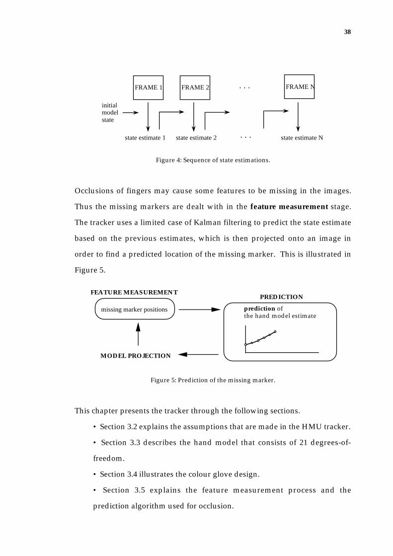
38
. . .FRAME 1 FRAME 2 FRAME N
initial modelstate
state estimate 1 state estimate 2 . . . state estimate N
Figure 4: Sequence of state estimations.
Occlusions of fingers may cause some features to be missing in the images.
Thus the missing markers are dealt with in the feature measurement stage.
The tracker uses a limited case of Kalman filtering to predict the state estimate
based on the previous estimates, which is then projected onto an image in
order to find a predicted location of the missing marker. This is illustrated in
Figure 5.
prediction of the hand model estimate
PREDICTIONFEATURE MEASUREMENT
MODEL PROJECTION
missing marker positions
Figure 5: Prediction of the missing marker.
This chapter presents the tracker through the following sections.
• Section 3.2 explains the assumptions that are made in the HMU tracker.
• Section 3.3 describes the hand model that consists of 21 degrees-of-
freedom.
• Section 3.4 illustrates the colour glove design.
• Section 3.5 explains the feature measurement process and the
prediction algorithm used for occlusion.

39
• Section 3.6 explains the theory and implementation details of the state
estimation process that uses the projection of the model state and the
measured features.
• Then finally, section 3.7 summarises the tracking process.
3.2 Assumptions
3.2.1 The signing speed
The HMU tracker employs a model based visual tracking algorithm that uses
the Newton style local optimisation approach which handles only a small
search space. Therefore it requires the predicted model state (according to the
previous estimate) to be near to the state captured in the image. Consequently,
the initial hand model must be close to the first image frame, and the change in
the hand state from one frame to the next in the sequence must be limited.
Dorner's experiments (1994A) showed that by assuming a frame rate of 60 Hz
(that is, 60 frames per second), it is possible to open or close a hand in 3-4
frames, and one can make a 30cm sweep through the air in the same time in
the extreme case. However, sign language is usually performed at a slower
rate. To test the tracker, without having a real-time image capturing facility,
Dorner generated a sequence of still frames made to resemble frames of a
movie sequence as closely as possible. Regh and Kanade used an image
acquisition rate of 10-15 Hz to limit the change in hand state. For the HMU
system development, the available facility could only provide the acquisition
rate of 4-5 Hz, and thus the movement of the hand is slowed down to a rate so
that a movement such as closing the hand is performed in about 6 frames.

40
3.2.2 Features and Occlusions
The HMU system uses the joint positions as features, and a colour-coded glove
is used to facilitate an efficient location of the joints in the images. Ring
markers for the finger joints and tips as well as the wrist are used so that
markers could still be detected from various viewing angles. The HMU
system employs only one camera, and it would be impossible to avoid
occlusion of the markers in the hand movement from one viewpoint. In order
to cope with the failure of the marker detection due to shadows and occlusion,
a prediction algorithm is introduced, which is a limited case of Kalman
filtering, in order to predict the hidden marker location. The prediction relies
on the changes of 3-D hand postures in previous frames in order to determine
the marker location. Thus it is assumed that while hidden, the joint
representing the marker moves at the average velocity calculated from the 6
previous frames, prior to it appearing in the image again.
3.3 The Hand Model
From a mechanical point of view, the joints of the hands are end points of
bones with constant length, as well as the points of connection between motion
units, and it is the displacement of the joints which causes the changes in hand
configuration. Assuming that the motion units (namely, finger segments) are
rigid, their configuration can be described by using both translation and
rotation parameters.
A complete hand model, as shown in Figure 6, involves the use of 26 degrees-
of-freedom, being 3 for the translations of the hand in the x, y, and z directions,
3 for the wrist rotations, and 4 for the joint rotations of each of the five fingers,
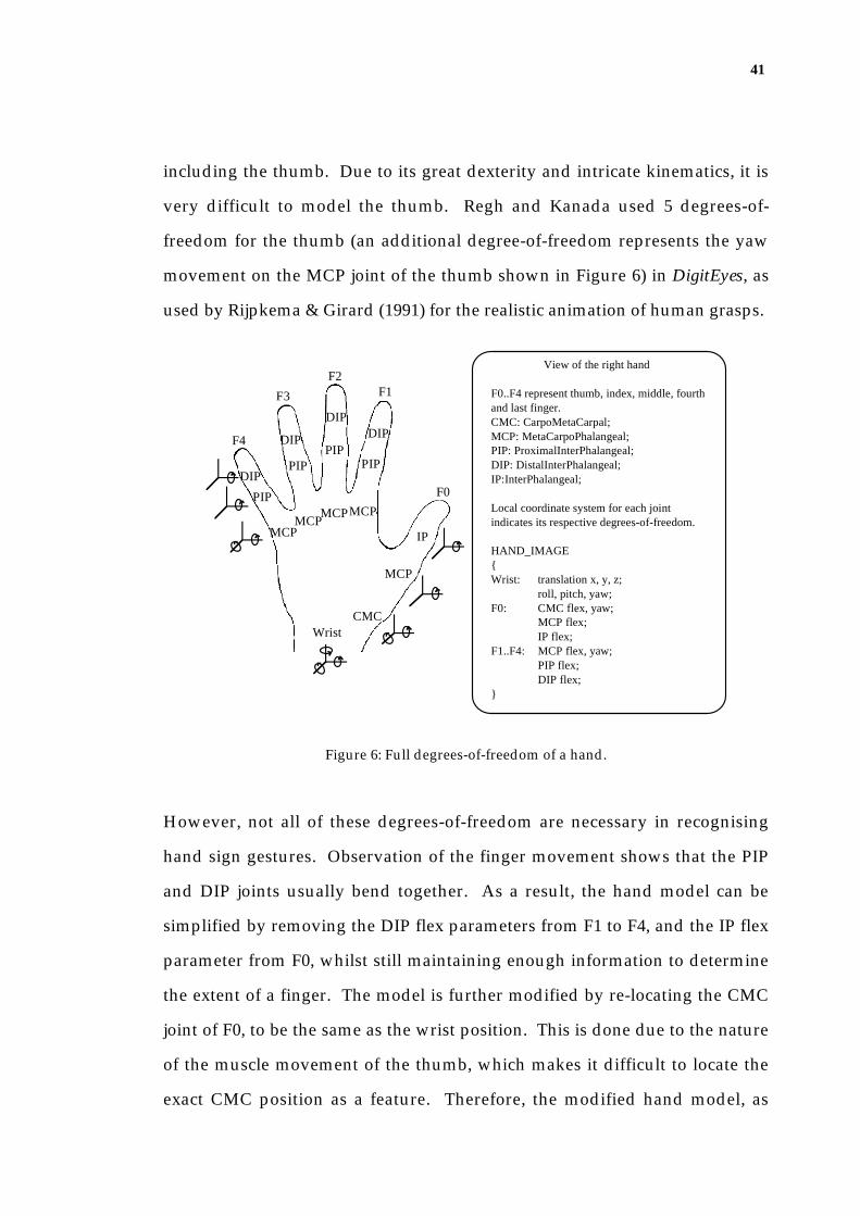
41
including the thumb. Due to its great dexterity and intricate kinematics, it is
very difficult to model the thumb. Regh and Kanada used 5 degrees-of-
freedom for the thumb (an additional degree-of-freedom represents the yaw
movement on the MCP joint of the thumb shown in Figure 6) in DigitEyes, as
used by Rijpkema & Girard (1991) for the realistic animation of human grasps.
View of the right hand
F0..F4 represent thumb, index, middle, fourth and last finger.CMC: CarpoMetaCarpal;MCP: MetaCarpoPhalangeal;PIP: ProximalInterPhalangeal;DIP: DistalInterPhalangeal;IP:InterPhalangeal;
Local coordinate system for each joint indicates its respective degrees-of-freedom.
HAND_IMAGE{Wrist: translation x, y, z;
roll, pitch, yaw;F0: CMC flex, yaw;
MCP flex;IP flex;
F1..F4: MCP flex, yaw;PIP flex;DIP flex;
}
F1F2
F3
F4
MCP
IP
MCP
PIP
DIP
CMC
MCPMCP
MCP
PIP
DIP
DIP
PIP
F0
Wrist
DIP
PIP
Figure 6: Full degrees-of-freedom of a hand.
However, not all of these degrees-of-freedom are necessary in recognising
hand sign gestures. Observation of the finger movement shows that the PIP
and DIP joints usually bend together. As a result, the hand model can be
simplified by removing the DIP flex parameters from F1 to F4, and the IP flex
parameter from F0, whilst still maintaining enough information to determine
the extent of a finger. The model is further modified by re-locating the CMC
joint of F0, to be the same as the wrist position. This is done due to the nature
of the muscle movement of the thumb, which makes it difficult to locate the
exact CMC position as a feature. Therefore, the modified hand model, as

42
shown in Figure 7, consists of five finger mechanisms each of which has 3
degrees-of-freedom, attached to a 6 degrees-of-freedom base (3 for the
translations and 3 for the rotations).
F1
F2
F3
F4
MCP
CMC
MCP F0
PIP
Wrist
TIP
TIP
Trans(x1, 0,0)Trans(0,y1,0)
Trans(dx3,0,0)
Trans(dx4,0,0)
xy
zTrans(dx1,0,0)
Trans(dx2,0,0)
Trans(g0, 0, 0)
Trans(0,g1, 0)
Trans(0,0,g2)
z
x
y
world coordinate frame
x
y
z
t2
z
x
y
g3
g4
g5
x
y
z
x
y
z
t1
t3
a1
a2
a3
b2
b1
b3
d3
d2
d1
r3
r2r1
Figure 7: Hand model - the base coordinate frame for each joint and their
transformation through rotations and translations.
The wrist and the MCP joints of F1, F2, F3, and F4 form the static part of the
palm, almost resembling a triangular shape. The palm's location and
orientation are represented by the 6 degrees-of-freedom of the wrist. The
fingers are assumed to be multi-branched kinematic chains attached to the
palm at the MCP joints, which are the finger base joints in the frame of the

43
palm. The fingers behave like planar mechanisms where the yaw movement
rotates the plane of the finger relative to the palm, whilst maintaining the
finger and palm planes orthogonal, and the two flex movements determine the
finger's configuration within the plane. Note that in the actual hand, parts of
the MCP-PIP link are enclosed with muscles and form part of the palm.
The palm orientation and translation parameters (belonging to the wrist) affect
all five finger mechanisms. The movement of one finger is independent of the
movement of the other fingers, for example, MCP joint angle change of F1
results in the configuration change of F1 only, not affecting the configuration
of the other fingers. Thus the hand tracking is performed by firstly tracking
the whole hand (palm) orientation and translation, and, then based on this
result, tracking the individual fingers. Figure 8 shows the 6 articulated
mechanisms (palm, F1, F2, F3, F4 and F5) to be tracked, and also the
illustration of the yaw and flex movements of the index finger and the thumb.
I only use 3 degrees-of-freedom in the thumb model, where the CMC joint has
two degrees-of-freedom, one representing the yaw movement and the other
representing the flex movement, and the MCP joint has one degree-of-freedom
representing the flex movement. Note in this case, that the yaw movement of
the thumb has the same directional movement as the flexion movement of
other fingers, which is the movement away from the palm plane. Obviously,
the flex movement of the thumb is the same as the yaw movement of the other
fingers.
The hand model consists of the kinematic chains that describe the
transformation between attached local coordinate frames for each finger

44
segment, by using the Denavit-Hartenberg (DH) representation (Yoshikawa
1990, p. 33), which is a commonly used representation in the field of robotics.
Index finger side view
finger planea2
a3
palm plane
thumb planet2 palm plane
Thumb side view
a1
base joint A
t1
t3
base joint B
base joint A
base joint B
Figure 8: Graphical illustration of the finger and thumb model.
For example, the transformation matrix for the wrist segment may be
calculated as follows:
Toriginwrist = Trans(γ 0 ,0,0) • Trans(0,γ 10) • Trans(0,0,γ 2 ) • Rot(z,γ 3 )
• Rot(y,γ 4 ) • Rot(x,γ 5 )(3.1)
For the other segments of F1 and similarly for F2, F3 and F4
TwristMCP = Trans(x1,0,0) • Trans(0, y2 0) • Rot(z,α1) • Rot(y,α2 ) (3.2)

45
TMCPPIP = Trans(dx3,0,0) • Rot(y,α3 ) (3.3)
TPIPTIP = Trans(dx4 ,0,0) (3.4)
and for the segments of F0:
TwristCMC = Rot(z,τ1) • Rot(y,τ2 )
TCMCMCP = Trans(dx1,0,0) • Rot(z,τ3 )
TMCPTIP = Trans(dx2 ,0,0)
Given the hand model, the vision-based tracker must extract features that
represent the model in the image. In the HMU system, the joint positions of
the hand are used as features and a colour-coded glove with joint markers is
used for an easier extraction of joint locations from the images.
3.4 Colour Glove
In order to locate the joint positions of the hand in images, a well-fitted cotton
glove is used and the joint markers are drawn with fabric paints. A surgical
glove would have better-fitted the hand, producing less creases during
movement, but there was not a feasible way to paint them. The markers are
placed at the joints represented in our hand model, which are the wrist, MCP,
PIP joints and TIP of four fingers, and MCP joint and TIP of the thumb.
Round reflector markers, such as those used in Johansson's experiment (1973)
represent a true joint position only if the marker is directly facing the camera.
They can represent quite a different joint position or even be hidden if the
fingers turn around. The HMU system employs ring-shaped joint markers
that wrap around the joints, as used by Kozlowski and Cutting (1977) in their
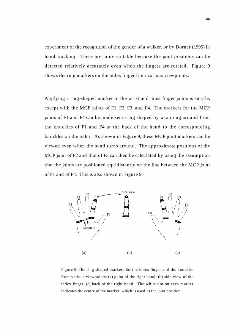
46
experiment of the recognition of the gender of a walker, or by Dorner (1995) in
hand tracking. These are more suitable because the joint positions can be
detected relatively accurately even when the fingers are rotated. Figure 9
shows the ring markers on the index finger from various viewpoints.
Applying a ring-shaped marker to the wrist and most finger joints is simple,
except with the MCP joints of F1, F2, F3, and F4. The markers for the MCP
joints of F1 and F4 can be made semi-ring shaped by wrapping around from
the knuckles of F1 and F4 at the back of the hand to the corresponding
knuckles on the palm. As shown in Figure 9, these MCP joint markers can be
viewed even when the hand turns around. The approximate positions of the
MCP joint of F2 and that of F3 can then be calculated by using the assumption
that the joints are positioned equidistantly on the line between the MCP joint
of F1 and of F4. This is also shown in Figure 9.
F4
F3F2
F1
F0
calculate
x x
side view
F0
F1F2
F3
F4
(a) (b) (c)
Figure 9: The ring shaped markers for the index finger and the knuckles
from various viewpoints: (a) palm of the right hand; (b) side view of the
index finger; (c) back of the right hand. The white dot on each marker
indicates the centre of the marker, which is used as the joint position.

47
Therefore, the colour glove consists of 13 markers: 2 ring markers for each of
the five fingers, 2 semi-ring markers for the knuckles, and a ring marker for the
wrist. When the respective movements are recorded in the images, it is
necessary to recognise which joint each marker belongs to. This
correspondence problem requires a methodology to represent each marker
distinctively by using various shape markers or colours. However, it is
extremely difficult to find 13 different shape markers that can be robustly
distinguished on the images. Alternative option is to use a unique colour for
each marker. Distinction of the different colours appearing in the image not
only depends on the colour applied on the glove but also the spectral
distribution of the light illuminating the surface, as well as the quality of the
camera. Our experiments show that it is impossible to find 13 distinct colours
in the fabric paint range or by mixing colours together, that can be
distinguished in the images which are captured under a normal office lighting
environment (the experiment being conducted under florescent light) using a
video recorder. This was because when fingers move, they project shadows on
other markers which change the shades of the colour in the images. As a
result, it was found that about six colours could be distinguished with any
degree of robustness and consistency.
One way to use this limited number of colours for marking many joints would
be to use multi-ring markers such as the ones used by Dorner. Dorner used 3
ring markers, where for each marker the top and bottom rings represent the
joint within the finger, and the middle ring identifies the finger. However,
with more marker area to process, the marker extraction would be
computationally more expensive. It is also the case that colour patches on any
two parts of the hand can easily become neighbours in the image, which

48
creates the unexpected and undesired illusion of a marker. The HMU system
uses simple markers that enable a quick marker extraction by image operators,
but with the intention to solve the correspondence problem of recognising to
which joint the marker belongs.
The glove used in the HMU system is shown in Figure 10.
Figure 10: Colour coded glove.
The TIP and PIP joint markers of a finger have the same colour marker, and
each finger has a distinct colour: blue for F0, fluorescent orange for F1, green
for F2, violet for F3, and magenta for F4. Yellow is used for the knuckle
indicators (the MCP joints of F1 and F4), and the wrist marker is in green, the
same colour as the F2 markers.
Note that the PIP joint markers are placed slightly below the actual joints in
order to reduce the impact of crease when fingers flex.

49
3.5 Feature Measurement
With the aid of a colour coded glove, the HMU tracker can extract the features
(that are wrist and joint positions of the fingers) from an image. An image is of
size 256 pixel width by 192 pixel height, and colour is encoded in 24 bits.
The feature measurement requires the following steps:
1. A colour segmentation process, where a colour image is converted into
a colour-coded array and the marker colours are identified;
2. A marker detection process, where for each marker, the centre of mass
is determined by search and region-growing algorithms on the basis of
the colour-coded array; and
3. An identification process, whereby once all marker locations have been
found, the corresponding 3-D joint for each marker location is identified
by using a joint-correspondence algorithm.
3.5.1 Colour segmentation
Colours can be specified by the spectral energy distribution of a light source.
This visual effect of the spectrum distribution has three components: the
dominant wavelength corresponds to the subjective notion of hue (that is the
colour we "see"); purity corresponds to saturation of the colour; and the
luminance is the amount of light (Foley & Van Dam 1984). The colours in the
digital image are, however, represented by the Red-Green-Blue (RGB) model
and there are various ways of segmenting the colours, such as directly
thresholding the raw RGB values, or using the chromacity values which
depend only on hue and saturation but can be made independent of the
amount of luminous energy by normalising against illuminance. The direct

50
use of this RGB model is not particularly easy because it does not directly
relate to our intuitive colour notion of hue, saturation, and brightness. Thus,
converting the RGB model to the Hue-Saturation-Value (HSV) model (Smith
1978) provides an easier way from the programmer's point of view to
determine the colour of interest for the purpose of segmentation. The HSV
model, and its relation to the RGB values are shown in Figure 11.
White
H
V
S
Green Yellow
Cyan Red
Blue Magenta
Black
1.0
0.0
White
Green Yellow
Cyan Red
Blue Magenta
(a) (b)
Figure 11: The HSV and RGB colour models (Adapted from Foley and Van
Dam, 1984): (a) single hexcone HSV colour model (note that the “V” and
“S” axis are orthogonal, and “H” indicates the rotation about the “V” axis);
(b) RGB colour cube viewed along the principal diagonal (for both (a) and
(b), the solid lines indicate the visible edges, and the dashed lines represent
the invisible ones).
Figure 11(a) shows the hexcone where the top of the hexcone contains
maximum value (intensity) colours. The top corresponds to V=1.0, which
corresponds to the surface seen by looking along the principal diagonal of the
RGB colour cube from white towards black. This is shown in Figure 11(b). In
the HSV hexcone, the angle around the vertical axis with red at 0o represents
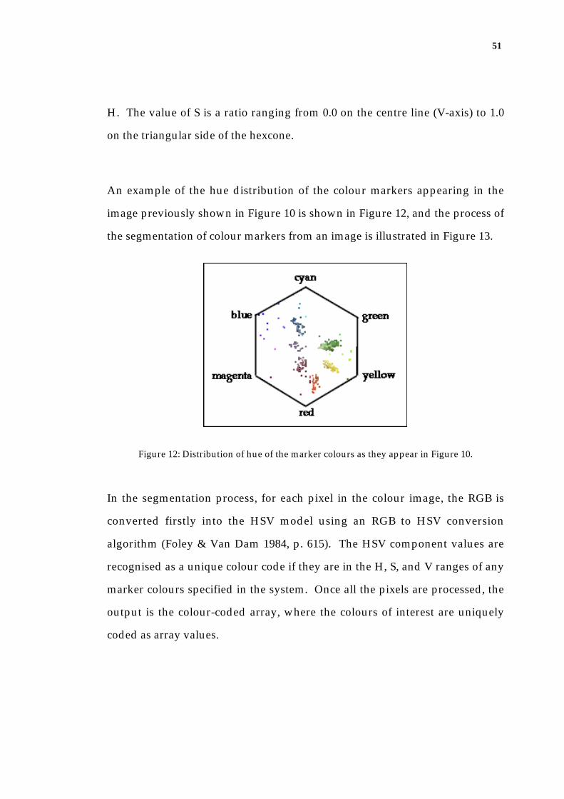
51
H. The value of S is a ratio ranging from 0.0 on the centre line (V-axis) to 1.0
on the triangular side of the hexcone.
An example of the hue distribution of the colour markers appearing in the
image previously shown in Figure 10 is shown in Figure 12, and the process of
the segmentation of colour markers from an image is illustrated in Figure 13.
Figure 12: Distribution of hue of the marker colours as they appear in Figure 10.
In the segmentation process, for each pixel in the colour image, the RGB is
converted firstly into the HSV model using an RGB to HSV conversion
algorithm (Foley & Van Dam 1984, p. 615). The HSV component values are
recognised as a unique colour code if they are in the H, S, and V ranges of any
marker colours specified in the system. Once all the pixels are processed, the
output is the colour-coded array, where the colours of interest are uniquely
coded as array values.

52
colour image
R: 1.0G: 1.0B: 0.0
RGBtoHSV algorithm
H: 60S: 1.0V: 1.0
Colour coding
colour coded array
5
Colour code table
rangesfor H
rangesfor S
rangesfor V
colourcode
colourname
0
1
2
3
4
5
blue 186 .. 234 0.3 .. 0.9 0.2 .. 1.0
orange 0 .. 19.8 0.5 .. 1.0 0.3 .. 1.0
purple 234 .. 342 0.1 .. 1.0 0.1 .. 0.8
green 84 .. 138 0.1 .. 1.0 0.2 .. 1.0
magenta 342 .. 360 0.3 .. 0.9 0.1 .. 0.8
yellow 42 .. 84 0.4 .. 1.0 0.3 .. 1.0
Figure 13: Colour segmentation process.
3.5.2 Marker Detection
While a colour-coded array provides easier detection of pixels that have the
same colour as the marker, an efficient marker detection also requires the
appropriate pixel positions to start the search for each marker. Other tracking
systems generally use a prediction algorithm to determine search positions for
feature detection in the subsequent sequence, whereas the HMU system uses
the marker positions of the previous frame as the expected marker positions to
begin the search. This is only possible because the sequence of images
acceptable for the tracker contains only a small movement between frames as
discussed earlier in section 3.2.1.

53
Using the colour-coded array, each marker position is detected using the
following process:
{Assuming: each pixel in the colour coded array is represented by
p(row, col, colour); an expected marker position is row=R, col=C; and
the marker I am searching for has colour K.}
1. Initialise offset_size=1
2. Search the surrounding pixels that were not previously visited using
the rectangular shape scan from
p(R-offset_size, C-offset_size, colour) to
p(R+offset_size, C+offset_size, colour).
If an unvisited pixel with the colour K, that is p(r, c, K), is found then
continue, otherwise, go to step 6.
3. Use a region_growing algorithm1 from p(r, c, K) to find the area of the
marker. The visited pixels are marked with the corresponding marker
identity number and the centre of mass is calculated.
4. If the area is too small (that is less than 30% of the expected marker
size), then ignore it as noise, and return to step 2 to continue the search.
5. A marker is found, store the centre of mass of the marker area.
6. Increase the offset_size by 1
7. If offset_size is less than MAX_search_size, then go to step 2.
8. Stop the marker search.
1A region-growing algorithm can be found in Dorner’s thesis (Dorner 1994A, p.29).
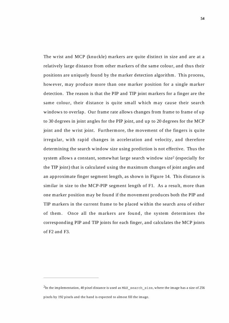
54
The wrist and MCP (knuckle) markers are quite distinct in size and are at a
relatively large distance from other markers of the same colour, and thus their
positions are uniquely found by the marker detection algorithm. This process,
however, may produce more than one marker position for a single marker
detection. The reason is that the PIP and TIP joint markers for a finger are the
same colour, their distance is quite small which may cause their search
windows to overlap. Our frame rate allows changes from frame to frame of up
to 30 degrees in joint angles for the PIP joint, and up to 20 degrees for the MCP
joint and the wrist joint. Furthermore, the movement of the fingers is quite
irregular, with rapid changes in acceleration and velocity, and therefore
determining the search window size using prediction is not effective. Thus the
system allows a constant, somewhat large search window size2 (especially for
the TIP joint) that is calculated using the maximum changes of joint angles and
an approximate finger segment length, as shown in Figure 14. This distance is
similar in size to the MCP-PIP segment length of F1. As a result, more than
one marker position may be found if the movement produces both the PIP and
TIP markers in the current frame to be placed within the search area of either
of them. Once all the markers are found, the system determines the
corresponding PIP and TIP joints for each finger, and calculates the MCP joints
of F2 and F3.
2In the implementation, 40 pixel distance is used as MAX_search_size, where the image has a size of 256
pixels by 192 pixels and the hand is expected to almost fill the image.
55
wrist
MCPpred
PIPpred
TIPpred
MCPcurr
PIPcurrTIPcurr
search window for TIPcurrMAX_search_size
Figure 14: Search window.
3.5.3. Imposter or Missing Markers
For the palm model, three markers (that are the wrist joint and the MCP joints
of F1 and F4) need to be found. For a finger, two markers (the PIP and TIP
joints) are expected to be found. As the fingers bend and the wrist rotates
during the movement, some of the markers may be difficult to find due to
overlap and occlusion of finger joints. Additionally, more than two markers
can be apparently detected because of an imposter marker that is detected as a
result of a split of a marker due to occlusions, or as a result of noise.
Currently, the imposter markers are eliminated by choosing the necessary
number of the larger size markers. Since the finger joint markers are quite
small, the split of the marker usually produces two very small areas (since it is
covered by another finger) which would be eliminated as noise. A further
problem results from occluded (or missing) markers. As a finger flexes, the
TIP marker may overlap with the PIP marker, resulting in the marker
detection algorithm producing only one marker position.

56
The imposter or missing marker problem also exists with the palm markers
(the MCP joint markers for F1 and F4). The fingers (especially the index finger
and the last finger) may partially or completely occlude the palm markers as
they flex. The palm markers are larger, and the partial occlusion may result in
a significantly different location of the markers from the actual, which is
critical for the tracker. The HMU prevents such an incident by observing the
marker size so that if a sudden change of a palm marker size occurs from the
previous frame, the system assumes the marker to be partially occluded and
regards it as a missing marker.
The HMU system deals with the missing marker problem by predicting the
location of the missing marker. This can be achieved in two ways:
• Use the changes of the 2-D marker positions from a few previous
images in order to determine the expected change of 2-D direction and
the distance from the previous frame, which produces a predicted joint
marker position.
• Use the changes of the 3-D model state estimates of the previous frames
in order to predict the 3-D model state (for all parameters of the model)
that may appear in the image, and generate the predicted joint positions
by projecting this state onto an image.
The HMU system uses 3-D state estimates in predicting the joint positions, as
the 3-D model provides a more accurate approximation.

57
3.5.3.1 Prediction algorithm
A limited case of the Kalman Filter (Du Plessis 1967; Sorenson 1970) is used to
observe the model estimates that were produced by the tracker in the 6
previous frames in order to predict the joint angles of a finger model in the
current frame. Each parameter of a mechanism is predicted using the
following method.
Parameter state vector
For a parameter α , Α(k) is the parameter state vector at time t(k) and is
defined as
Α(k) = α(k), α(k), α(k − 1), α(k − 2), α(k − 3), α(k − 4)( )T ,
where velocity α(k) represents the changes of the parameter value from time
t(k − 1) to time t(k) , that is α(k) = α(k) − α(k − 1). Note that Α(k) is the
transposed vector of α(k), α(k), α(k − 1), α(k − 2), α(k − 3), α(k − 4)( ) .
Parameter state transition
The parameter state at time t(k + 1) is calculated by using the state transition
matrix, F , which maps from the parameter state at time t(k) to its state at time
t(k + 1) ,
Α(k + 1) = FΑ(k) + v(k) ,
where the noise v(k) is assumed to be Gaussian, zero-mean, and temporally
uncorrelated, and

58
F =
115
∆t15
∆t15
∆t15
∆t15
∆t
0 1 0 0 0 0
0 0 1 0 0 0
0 0 0 1 0 0
0 0 0 0 1 0
0 0 0 0 0 1
⎛
⎝
⎜⎜⎜⎜⎜⎜⎜⎜
⎞
⎠
⎟⎟⎟⎟⎟⎟⎟⎟
,
where ∆t = t(k + 1) − t(k).
The state transition matrix uses weighted velocities of the previous changes in
parameter values in order to deal with the unpredictable behaviour of the
finger movement that changes its velocity and acceleration unexpectedly.
Parameter prediction
The prediction z(k) of the parameter α at time t(k) is
z(k) = HA(k) + w(k)
where w(k) are assumed to be Gaussian, zero-mean, temporally uncorrelated
noise, and
H = 1, 0, 0, 0, 0, 0( ) .
The noise represents the difference between the true model state appearing in
the image and its estimate that was produced by the tracker in each frame.
The predicted hand state in the new frame is calculated by using the Kalman
filter prediction equations. However, in the actual implementation, Gaussian
noise is ignored in calculating the angle prediction because the size and
direction of the movement of the finger is irregular from frame to frame, thus
the inclusion of noise in the formula causes inaccuracy in prediction.

59
The prediction process accommodates physiological constraints of the hand in
order ensure the predicted hand posture is physiologically possible. For the
movement of F0, the following constraints are enforced:
• The CMC joint moves up to 45 degrees away from the palm plane (that
is the yaw movement).
• The CMC joint flexes up to 50 degrees towards the fingers from the
fully stretched thumb posture, and does not flex backwards.
• The MCP joint flexes up to 110 degrees.
For the movement of F1, F2, F3 or F4, the following constraints are enforced:
• The MCP joint moves up to 20 degrees to the right or left from the
straight finger posture (that is the yaw movement).
• The MCP joint flexes up to 90 degrees forward, and does not flex
backwards.
• The PIP joint flexes up to 90 degrees forward, and does not flex
backwards.
The prediction algorithm produces a joint angle outside its physiologically
possible range, it simply enforces the closest limit which may be the maximum
or minimum angle allowed in the constraint.
The projection of the model state is described later in section 3.6.1. The result
of this is that the projected joint positions replace missing marker positions of
a finger model using the following algorithm.
1. If any of the PIP and TIP marker for the finger model is not found, then
calculate the prediction of both the PIP and TIP joint positions.
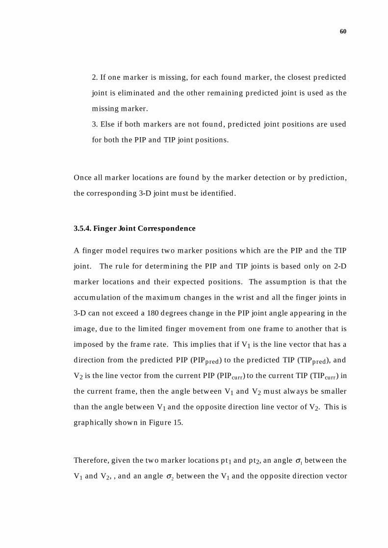
60
2. If one marker is missing, for each found marker, the closest predicted
joint is eliminated and the other remaining predicted joint is used as the
missing marker.
3. Else if both markers are not found, predicted joint positions are used
for both the PIP and TIP joint positions.
Once all marker locations are found by the marker detection or by prediction,
the corresponding 3-D joint must be identified.
3.5.4. Finger Joint Correspondence
A finger model requires two marker positions which are the PIP and the TIP
joint. The rule for determining the PIP and TIP joints is based only on 2-D
marker locations and their expected positions. The assumption is that the
accumulation of the maximum changes in the wrist and all the finger joints in
3-D can not exceed a 180 degrees change in the PIP joint angle appearing in the
image, due to the limited finger movement from one frame to another that is
imposed by the frame rate. This implies that if V1 is the line vector that has a
direction from the predicted PIP (PIPpred) to the predicted TIP (TIPpred), and
V2 is the line vector from the current PIP (PIPcurr) to the current TIP (TIPcurr) in
the current frame, then the angle between V1 and V2 must always be smaller
than the angle between V1 and the opposite direction line vector of V2. This is
graphically shown in Figure 15.
Therefore, given the two marker locations pt1 and pt2, an angle σ1 between the
V1 and V2, , and an angle σ2 between the V1 and the opposite direction vector

61
of V2, the following rule is used to determine the PIPcurr and TIPcurr
correspondence:
If cos( σ1) > cos ( σ2) then PIPcurr = pt1, TIPcurr=pt2,
else PIPcurr=pt2, TIPcurr= pt1. (rule 2.1)
wristpred
MCPpred
PIPpred
TIPpred
wristcurr
MCPcurr
PIPcurr
TIPcurr
V1
V2
s1s2
V1
V2
Figure 15: Finger joints changes and the correspondence problem.
This joint correspondence is a difficult problem, and the above rule is certainly
not completely reliable. For example, when two markers moving towards
each other overlap, the possible movements of the markers in the next frame
are shown in Figure 16 and these include the following:
(1) both markers moving in their corresponding predicted moving
directions;
(2) both markers moving in opposite directions to their corresponding
predicted moving directions; or
(3) both markers moving together to a predicted moving direction of one
of the markers.

62
marker 1
marker 2
marker 1marker 2
marker 1
marker 2
marker 2
marker 1
occlusion case (1) case (2) case (3)
Figure 16: Occluded joints and their moving directions - the 3 possible following moves.
The joint correspondence rule (rule 2.1) is only effective for case (1), as for
cases (2) and (3), the prediction may produce a wrong correspondence result.
After one or more frames of incorrect correspondence, it may no longer be
possible to generate the finger configuration to fit the markers. This is called a
'singularity' problem in robotics, where the joint positions indicate a
configuration beyond the reach of the mechanism. The HMU tracker
determines this situation by observing firstly whether the behaviour of the
tracker that fails to converge, and secondly if the distance between the joint
positions is relatively small. If this situation occurs, the HMU system re-orders
the PIP-TIP joints and tracks the configuration for the recovery of false
correspondence.
3.6 The State Estimation
Given a 2-D image and the 3-D predicted model state (the current estimate in
our system), the aim of the state estimation is then to calculate the 3-D
parameter corrections which need to be applied to the model state to fit the
pose appearing in the image. This correction is obtained by applying Lowe's
object tracking algorithm (Lowe 1991).

63
3.6.1 Projection of the 3-D Model onto a 2-D Image
In order to compare a given 3-D pose of a hand model to the hand shape
appearing in the image, the hand model must be projected onto the image of a
virtual camera. The pinhole camera model shown in Figure 17 illustrates the
perspective projection that simulates the process of taking a video image of a
3-D point of a hand model.
f
y
x
centre ofprojection
(x,y,z)T
v
u(u,v,f)T
Figure 17: Perspective projection in the pinhole camera model. The hand coordinates
(x, y, z)T are projected through the centre of the projection (pinhole) onto the image plane
located at z=f; the projection has the image coordinates (u,v, f )T.
The pinhole models an infinitesimally small hole at the origin (that is the
centre of projection) and its image plane parallel to the x-y plane at z-value f.
Through the pinhole, light enters before forming an inverted image on the
camera surface facing the hole. To avoid the inverted view of the image, a
pinhole camera is modelled by placing the image plane between the focal
point of the camera and the hand.

64
The hand coordinates (x, y, z)T that represent a point on the finger tip of F4, are
projected along a ray of light through the pinhole onto the image plane at
(u,v, f )T . The coordinates u and v on the image plane are given by
u = fx
z, and v = fy
z. (3.5)
Although this projection from 3-D to 2-D is a nonlinear operation, it is yet a
smooth and well behaved transformation (Lowe 1991). Transformation of the
projected joint points due to the 3-D rotations prior to projection could be
represented by a function of the sine and cosine of the rotation joint angles.
Translation of the hand towards or away from the camera generates
perspective distortion as a function of the inverse of the distance, and the
translation parallel to the image plane is linear. To solve this problem of
recovering the 3-D pose from 2-D image information, the algorithm uses
Newton's method (McKeown et al. 1990) which assumes that the function is
locally linear. Newton's method requires an appropriate initial choice for the
parameters, and corrects the 3-D hand model towards the pose appearing in
the image, through a series of iterative steps.
3.6.2 Definitions
Given the finger joint locations appearing in the image and the initial choice of
parameters (that are the joint angles of the predicted configuration) for the
hand model, the objective here is to find the correction vector for all
parameters (that are translation and orientation parameters of palm and
fingers) of the hand model so that the model can be re-configured to fit the
posture represented in the image features.
65
Parameters
Let the parameter vector be,
α = α1, α2 , L αn( )T , (3.6)
where n is the total number of parameters. The palm model consists of 6
parameters (that is, the x, y, and z translation parameters and 3 rotation
parameters for the wrist). A finger uses 3 rotation parameters as previously
shown in the finger model, and 2 additional translation parameters are used to
deal with the noise. The noise parameters will be explained later in section
3.6.7.
Projected features
The projection of the ith joint onto an image as a function of the hand state α is
pi (α ) =pix (α )
piy (α )
⎛⎝⎜
⎞⎠⎟
.
For the whole hand, these vectors are concatenated into a single vector, and for
convenience, I define q1(α ) = p1x (α ), q2 (α ) = p1y (α ) etc., thus,
q(α ) =
p1x (α )
p1y (α )
M
pkx (α )
pky (α )
⎛
⎝
⎜⎜⎜⎜⎜⎜
⎞
⎠
⎟⎟⎟⎟⎟⎟
=
q1(α )
q2 (α )
M
qm−1(α )
qm (α )
⎛
⎝
⎜⎜⎜⎜⎜
⎞
⎠
⎟⎟⎟⎟⎟
, where k is the total number of joints.
Note that m = 2k . Tracking the palm or a finger requires 3 joints. Palm
tracking uses the wrist and the knuckles of F1 and F4, whereas finger tracking
uses the knuckle, PIP and TIP of the finger.

66
As an example of this projection function, the TIP position (let me call this the
kth joint) of the F1 finger model, (x, y, z) can be calculated by multiplying the
corresponding transformation matrices (matrices for connected finger
segments up to the joint position from the origin) which were previously
shown in equations 3.1 to 3.4 of section 3.3, describing the hand model. That
is,
ToriginTIP = Torigin
wrist • TwristMCP • TMCP
PIP • TPIPTIP , (3.7)
and the joint point of the hand coordinate system can be calculated as
x, y, z, 1( )T = ToriginTIP • 0, 0, 0, 1( )T .
Then the homogeneous hand coordinates (x, y, z,1)T can be defined as
(pkx , pky ,1)T by rewriting equation 3.5,
pkx
pky
1
⎛
⎝
⎜⎜
⎞
⎠
⎟⎟
=f 0 0 0
0 f 0 0
0 0 1 0
⎛
⎝
⎜⎜
⎞
⎠
⎟⎟
x
y
z
1
⎛
⎝
⎜⎜⎜⎜
⎞
⎠
⎟⎟⎟⎟
. (3.8)
Error Vector
The measured joint locations are the joint positions, which are obtained by the
feature extraction process from an image. Similarly to the projected joints, the
measured feature locations are concatenated into a single vector:
g =
b1x
b1y
M
bkx
bky
⎛
⎝
⎜⎜⎜⎜⎜
⎞
⎠
⎟⎟⎟⎟⎟
=
g1
g2
M
gm−1
gm
⎛
⎝
⎜⎜⎜⎜⎜
⎞
⎠
⎟⎟⎟⎟⎟
and then the error vector describing the differences between the projected and
measured joint positions is

67
e = q(α ) − g =q1(α ) − g1
M
qm (α ) − gm
⎛
⎝
⎜⎜
⎞
⎠
⎟⎟. (3.9)
3.6.3 Newton's Method
A vector of corrections c to be subtracted from the current estimate for α on
each iteration is computed using Newton's method as follows:
c = α (i) − α (i+1).
Using the Taylor's series, and assuming that q(α ) is a smooth function, I have
for α (1) close to α (0) , that is for small c ,
q(α (1) ) = q(α (0) ) + dq(α (0) )dα
c + 12!
d 2q(α (0) )dα 2 c( )2 +K
In the HMU tracker, α (0) is the previous estimate and q(α (0) )represents the
projected joint positions of the state of the previous estimate. Moreover, the
value q(α (1) ) may be the actual measurement, and it is the parameter α (1) that I
aim to estimate. Assuming then that the function is locally linear,
q(α (1) ) = q(α (0) ) + dq(α (0) )dα
c , (3.10)
and differentiating q ,
dq(α )dα
=
∂q1(α )∂α1
L∂qm (α )
∂α1
M O M∂q1(α )
∂αn
L∂qm (α )
∂αn
⎛
⎝
⎜⎜⎜⎜⎜
⎞
⎠
⎟⎟⎟⎟⎟
= J , (3.11)
where J is the Jacobian matrix of q .

68
Then, substituting 3.9 and 3.11 into the equation 3.10, I need to solve the
following equation for c :
e = Jc. (3.12)
This matrix equation states that the measured error should be equal to the sum
of all the changes in the error resulting from the parameter corrections. Using
Newton's method, if the system is locally linear, it can be solved in one
iteration. Otherwise, the calculation must be repeated by replacing the trial
point α (i) by α (i+1) = α (i) − c until all constraints in 3.12 are satisfied.
3.6.4 Minimisation
If there are more measurements (size of q , m) than parameters (size of α , n),
the system is over determined. Using Lowe's stabilisation technique which
will be shown later, my system will always be over-determined. Thus, instead
of solving for c exactly from 3.12, I aim to find the c that minimises the
magnitude of the residual:
min F(c) , where F(c) = Jc − e
which will give the same result as minimising the least squares error. That is
min Jc − e2.
To solve the minimisation problem, I find c that satisfies
dF(c)dc
= 0, (3.13)
and for which the second derivative is positive.
In order to calculate 3.13, the following method is derived.
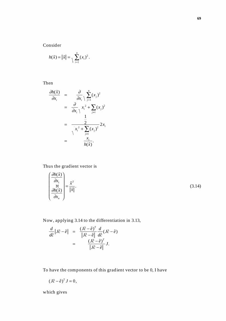
69
Consider
h( x) = x = (xi )2
i=1
n
∑ .
Then
∂h( x)∂xi
= ∂∂xi
(x j )2
j =1
n
∑
= ∂∂xi
xi2 + (x j )
2
j ≠ i∑
=
12
xi2 + (x j )
2
j ≠ i∑
2xi
= xi
h( x).
Thus the gradient vector is
∂h( x)∂x1
M∂h( x)∂xn
⎛
⎝
⎜⎜⎜⎜
⎞
⎠
⎟⎟⎟⎟
= xT
x. (3.14)
Now, applying 3.14 to the differentiation in 3.13,
d
dcJc − e = (Jc − e)T
Jc − e
d
dc(Jc − e)
= (Jc − e)T
Jc − eJ.
To have the components of this gradient vector to be 0, I have
(Jc − e)T J = 0 ,
which gives
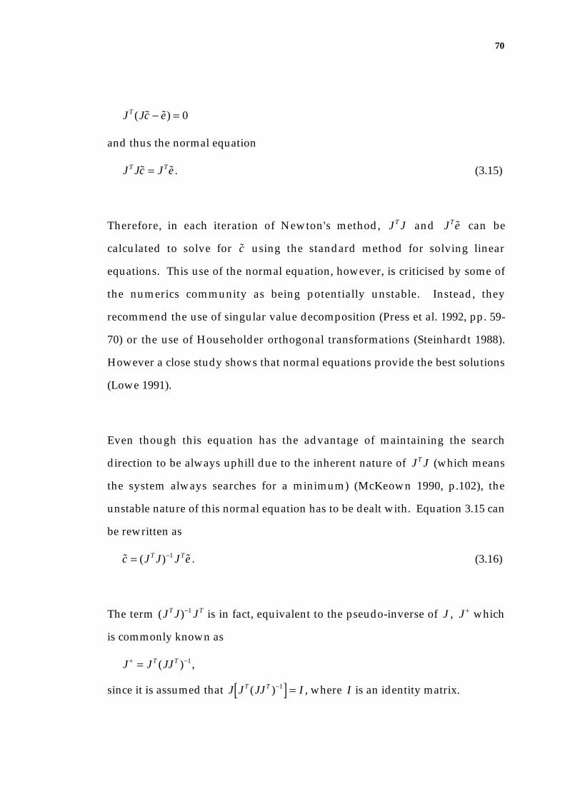
70
JT (Jc − e) = 0
and thus the normal equation
JT Jc = JTe . (3.15)
Therefore, in each iteration of Newton's method, JT J and JTe can be
calculated to solve for c using the standard method for solving linear
equations. This use of the normal equation, however, is criticised by some of
the numerics community as being potentially unstable. Instead, they
recommend the use of singular value decomposition (Press et al. 1992, pp. 59-
70) or the use of Householder orthogonal transformations (Steinhardt 1988).
However a close study shows that normal equations provide the best solutions
(Lowe 1991).
Even though this equation has the advantage of maintaining the search
direction to be always uphill due to the inherent nature of JT J (which means
the system always searches for a minimum) (McKeown 1990, p.102), the
unstable nature of this normal equation has to be dealt with. Equation 3.15 can
be rewritten as
c = (JT J)−1 JTe . (3.16)
The term (JT J)−1 JT is in fact, equivalent to the pseudo-inverse of J , J + which
is commonly known as
J + = JT (JJT )−1 ,
since it is assumed that J JT (JJT )−1[ ] = I , where I is an identity matrix.

71
In my tracking problem, J is an m × n matrix where n is the size of the
parameter (size of α ) and m is the size of the measurements (size of q ), where
m is always greater than n. This means that JJT is inherently singular, thus
instead it uses
J + = (JT J)−1 JT ,
since it is assumed that (JT J)−1 JT[ ]J = I , where I is an identity matrix.
Even when m > n , however, there is still a possibility that JT J is singular or
near singular at some trial point α (i). This problem is often dealt with by
adding a small positive quantity to each diagonal element to stabilise the
system. The reason is that JT J is inherently a positive semi-definite matrix
which has non-negative eigenvalues, and this modification would change it
into a positive definite matrix that is invertible. This stabilisation technique is
often used in tracking systems (Regh & Kanade 1995; Lowe 1990).
3.6.5 Lowe's Stabilisation and Convergence Forcing Technique
Lowe (1990) developed a stabilisation technique that is suitable for tracking
systems of complex objects such as the hand. Objects with many internal
parameters can often lead to an ill-conditioned solution due to problems such
as the difficulty in choosing the correct match between the many model and
image features. To deal with such difficulties, Lowe introduces prior
constraints on the desired solution which specify the default correction values
for the parameters. This is formulated as
J
I⎛⎝⎜
⎞⎠⎟c =
e
s
⎛⎝⎜
⎞⎠⎟
, (3.17)

72
where I is an identity matrix and si is the desired default value for parameter
i.
The constraints on the solution can be used to specify the parameter values in
the absence of further data, and in certain motion tracking problems they can
be used to predict the specific parameter estimates using the prior estimates.
As mentioned earlier, the Kalman Filter style prediction as a constraint implies
a weighted preference for a parameter value in later iterations of nonlinear
convergence. Because of the nature of the finger movement that changes its
acceleration rapidly and with irregular movement size, non-zero preferences
according to the prior parameter estimates are not applied in the HMU tracker.
Thus, I use zero corrections as the default solution.
The next step is to normalise the matrix equation in order to specify the trade-
offs between meeting the constraints from the data in equation 3.17, versus the
data of the prior model in equation 3.12. Thus each row of the matrix equation
is normalised to a unit standard deviation. The HMU system's image
measurements are in pixels, thus the standard deviation of 1 provides a good
estimate for the error in measuring the joint location in the image. Then
another normalisation is applied in order to employ a maximum limit
constraint on each parameter correction. Each row of the lower parts of the
matrix equation is normalised to the standard deviation of each parameter
change from one frame to the next, which is the limit on the acceleration of
each parameter from frame to frame. For translation parameters, a limit of up
to 50 pixels (within the 256 pixels width by 192 pixels height image frame) is
used as the standard deviation, but for rotational parameters, ranges from

73
π / 4 up to π / 2 , depending on the finger joint, are used as standard deviation.
A detailed description of these constraints is explained in section 3.6.8.
Therefore, given the standard deviation, σ i for parameter α i , normalising the
identity matrix applies weights to its diagonal elements. Each weight is
inversely proportional to the standard deviation of the corresponding
parameter for which the constraints are applied to its solution:
J
W⎛⎝⎜
⎞⎠⎟c =
e
Ws
⎛⎝⎜
⎞⎠⎟
, where Wii = 1σ i
.
This system is then minimised by solving the corresponding normal equations
using 3.15,
JTWT( ) J
W⎛⎝⎜
⎞⎠⎟c = JTWT( ) e
Ws
⎛⎝⎜
⎞⎠⎟
,
and this becomes
(JT J + WTW)c = JTe + WTWs .
This is similar to the stabilisation technique mentioned earlier that uses the
addition of a small constant to the diagonal elements of JT J .
Even with this stabilisation technique, it is still possible that the system will
fail to converge to a minimum, because this is a linear approximation of a
nonlinear system. Lowe's method (Lowe 1991) applies a scalar weight (λ ) to
the stabilisation to force the convergence. The scalar λ can be used to increase
the weight of stabilisation whenever divergence occurs, but a constant scalar of
64 is used in the HMU system to stabilise the system throughout the iterations.
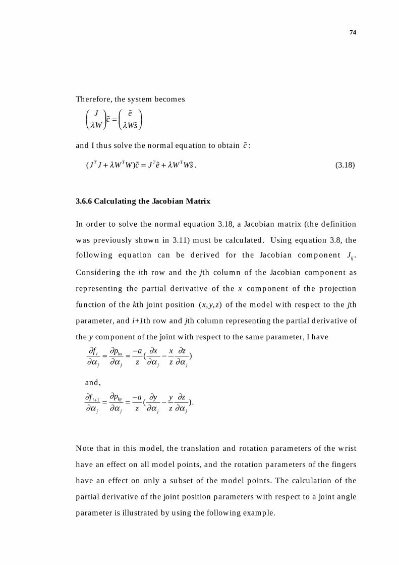
74
Therefore, the system becomes
J
λW⎛⎝⎜
⎞⎠⎟c =
e
λWs
⎛⎝⎜
⎞⎠⎟
and I thus solve the normal equation to obtain c :
(JT J + λWTW)c = JTe + λWTWs . (3.18)
3.6.6 Calculating the Jacobian Matrix
In order to solve the normal equation 3.18, a Jacobian matrix (the definition
was previously shown in 3.11) must be calculated. Using equation 3.8, the
following equation can be derived for the Jacobian component Jij .
Considering the ith row and the jth column of the Jacobian component as
representing the partial derivative of the x component of the projection
function of the kth joint position (x, y, z) of the model with respect to the jth
parameter, and i+1th row and jth column representing the partial derivative of
the y component of the joint with respect to the same parameter, I have
∂f i
∂α j
= ∂pkx
∂α j
= −a
z(
∂x
∂α j
− x
z
∂z
∂α j
)
and,
∂f i+1
∂α j
=∂pky
∂α j
= −a
z(
∂y
∂α j
− y
z
∂z
∂α j
).
Note that in this model, the translation and rotation parameters of the wrist
have an effect on all model points, and the rotation parameters of the fingers
have an effect on only a subset of the model points. The calculation of the
partial derivative of the joint position parameters with respect to a joint angle
parameter is illustrated by using the following example.
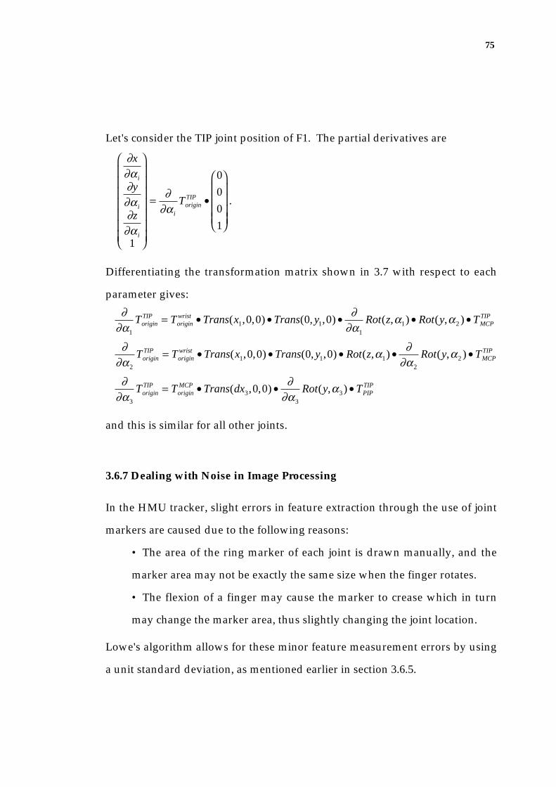
75
Let's consider the TIP joint position of F1. The partial derivatives are
∂x
∂α i
∂y
∂α i
∂z
∂α i
1
⎛
⎝
⎜⎜⎜⎜⎜⎜⎜
⎞
⎠
⎟⎟⎟⎟⎟⎟⎟
= ∂∂α i
ToriginTIP •
0
0
0
1
⎛
⎝
⎜⎜⎜⎜
⎞
⎠
⎟⎟⎟⎟
.
Differentiating the transformation matrix shown in 3.7 with respect to each
parameter gives:
∂∂α1
ToriginTIP = Torigin
wrist • Trans(x1,0,0) • Trans(0, y1,0) • ∂∂α1
Rot(z,α1) • Rot(y,α2 ) • TMCPTIP
∂∂α2
ToriginTIP = Torigin
wrist • Trans(x1,0,0) • Trans(0, y1,0) • Rot(z,α1) • ∂∂α2
Rot(y,α2 ) • TMCPTIP
∂∂α3
ToriginTIP = Torigin
MCP • Trans(dx3,0,0) • ∂∂α3
Rot(y,α3 ) • TPIPTIP
and this is similar for all other joints.
3.6.7 Dealing with Noise in Image Processing
In the HMU tracker, slight errors in feature extraction through the use of joint
markers are caused due to the following reasons:
• The area of the ring marker of each joint is drawn manually, and the
marker area may not be exactly the same size when the finger rotates.
• The flexion of a finger may cause the marker to crease which in turn
may change the marker area, thus slightly changing the joint location.
Lowe's algorithm allows for these minor feature measurement errors by using
a unit standard deviation, as mentioned earlier in section 3.6.5.
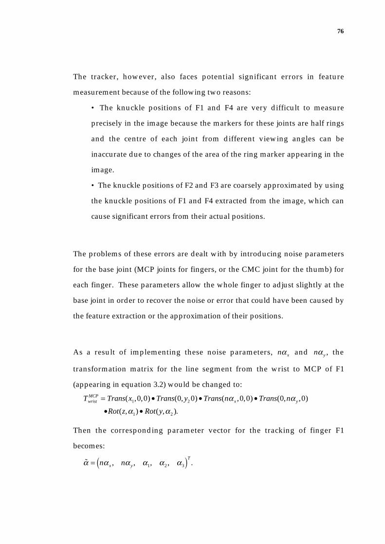
76
The tracker, however, also faces potential significant errors in feature
measurement because of the following two reasons:
• The knuckle positions of F1 and F4 are very difficult to measure
precisely in the image because the markers for these joints are half rings
and the centre of each joint from different viewing angles can be
inaccurate due to changes of the area of the ring marker appearing in the
image.
• The knuckle positions of F2 and F3 are coarsely approximated by using
the knuckle positions of F1 and F4 extracted from the image, which can
cause significant errors from their actual positions.
The problems of these errors are dealt with by introducing noise parameters
for the base joint (MCP joints for fingers, or the CMC joint for the thumb) for
each finger. These parameters allow the whole finger to adjust slightly at the
base joint in order to recover the noise or error that could have been caused by
the feature extraction or the approximation of their positions.
As a result of implementing these noise parameters, nα x and nα y , the
transformation matrix for the line segment from the wrist to MCP of F1
(appearing in equation 3.2) would be changed to:
TwristMCP = Trans(x1,0,0) • Trans(0, y2 0) • Trans(nα x ,0,0) • Trans(0,nα y ,0)
•Rot(z,α1) • Rot(y,α2 ).
Then the corresponding parameter vector for the tracking of finger F1
becomes:
α = nα x , nα y , α1, α2 , α3( )T.

77
3.6.8 Constraints: Joint Angle Change Limit from Frame to Frame
It was previously discussed in section 3.5.2 that the frame rate in the HMU
system allows certain ranges for the joint angle changes. During the tracking
process, however, the tracker sometimes does not converge to the solution,
producing outliers. If this continues for one or more frames, the changes of the
joint angles from the previous (acceptable) estimate to the current estimate
may be larger than the assumed joint angle change from frame to frame.
For the rotation angle parameters of all finger joints, the limit of π4 is used,
and for the wrist joint, the limit of π 2 is used. As for translation parameters of
the wrist, a change of 50 pixels is allowed from frame to frame; and when used
as noise parameters for each base joint, a limit of 2 pixels is used.
3.6.9 The State Estimation Algorithm
Given a predicted hand estimate and an image, the tracking algorithm for the
ith iteration is as follows:
1. Given a predicted hand estimate α (i), calculate the projected joint
positions, q .
2. Process the image to find joint locations, and determine the
measured joint positions, g , using the joint correspondence process.
3. Calculate the error vector e that is q − g .
4. For all j, if ej < ξ j , where ξ j is the small noise that may be caused by
feature extraction, then the system converged to a solution, thus, go
to step 8. Otherwise continue.
78
5. Calculate the Jacobian matrix and solve for the normal equation 3.18
to obtain the correction vector c .
6. Calculate the new estimate α (i+1) that is α (i+1) = α (i) − c .
7. Use the new estimate as the predicted hand estimate and repeat
from step 1 for the next iteration.
8. The model state estimate for the current frame is a(i).
This algorithm continuously searches for a convergence to a solution where
the Euclidean distances between the measured image features and the
projected model features (error vector elements) are smaller than the
threshold. However, if the convergence does not occur within the maximum
number of iterations that is enforced (20 is used as a maximum iteration), the
system analyses the previous iterations to determine the best fitting iteration
by comparing the average of the error vector elements amongst the iterations.
The model state estimation of the chosen iteration is used as a solution.
3.7 Summary
This chapter presented a 3-D model-based visual hand tracker that recovers 21
degree-of-freedom parameters of the hand from a colour image sequence. A
signer is required to wear a colour-coded glove where finger joints and tips as
well as the wrist are encoded with ring markers.
The hand tracker has a 3-D hand model that consists of 21 parameters
including translation and rotation parameters of finger joints and the wrist.
This hand model is a simplified version of the full degrees-of-freedom hand
model used by Dorner (1994A), and Regh and Kanade (1995). Given the initial

79
model state, the tracking is performed by incremental corrections to the 3-D
hand model state from one image to the next. One cycle of the model
correction is as follows:
• The joint markers are extracted from a colour image in order to
determine joint locations. This is achieved by segmenting marker colours
and detecting their locations from the colour images, followed by the
joint correspondence algorithm that determines each joint location. These
joint locations are used as image features in model fitting;
• For the model fitting process, Lowe's general tracking algorithm is
successfully implemented to recover 21 degrees-of-freedom of the hand.
The process compares the image features and the projected joint locations
of the 3-D hand model state in order to find corrections for all hand
model parameters by using a Newton style minimisation technique. It
has a stabilisation technique that forces convergence in the optimisation
process.
• The model state is updated according to the corrections that were
calculated.
The occlusion of the fingers or the shadows due to a lighting condition often
causes the joint markers to temporarily disappear in the image. The tracker
handles this problem by predicting joint marker locations in the corresponding
image. Predictions of joint positions are calculated by predicting the 3-D
model state by using 6 previous state estimates and projecting the predicted
model state on to an image plane.

80
As a result of the sequential state estimations for the image sequence, the
HMU hand tracker produces a sequence of 3-D configuration data sets where
each set consists of 21 parameters that represent a 3-D hand posture.
81
Chapter 4
Hand Motion Data Classification
The HMU classifier recognises the 3-D kinematic sequence that was extracted
from the hand tracker as a sign. The kinematic sequence contains the hand
movement that starts from a specified neutral hand posture (that is an Auslan
basic hand posture, known as posture_flat0) and then performs the sign. Each
frame in the sequence represents a hand posture and the changes of hand
postures along the sequence represent hand motion. Throughout this chapter,
a frame in the 3-D kinematic sequence will be referred to as a kinematic data
set, and an example of the set is often defined as kin_pos. From the previously
shown Figure 7, kin_pos consists of 15 finger joint angles (3 degrees-of-freedom
in the MCP and PIP joints of each of the five fingers). That is,
kin_ pos = (τ1,τ2 ,τ3,α1,α2 ,α3,β1,β2 ,β3,δ1,δ2 ,δ3,ρ1,ρ2 ,ρ3 ) .
Note here that even though the tracker recovers 21 degrees-of-freedom of the
hand, the 6 parameters of the wrist translation and orientation are not used for
sign classification.

82
4.1 Overview of the Chapter
The HMU classifier is capable of imposing expert knowledge of the
input/output behaviour on the system and yet also supports data
classification over a range of individual hand movements or errors in the
movement measurement. This is achieved by using an adaptive fuzzy expert
system.
Given a sequence of kinematic configuration data that was extracted from the
tracker, the sign recognition process classifies the sequence as a sign. For each
frame, Auslan hand postures are recognised. The motion is then analysed by
using the changes in the hand postures throughout the sequence. By using the
initial and final hand postures as well as the motion in-between, the output
sign is generated. The recognition processes of both postures and signs use a
fuzzy inference engine.
The fuzzy expert system relies on the rules that define the postures and signs.
Posture and sign rules are stored in their corresponding knowledge bases that
are called rule bases throughout this chapter. In addition, the fuzzy expert
system has an adaptive engine using a supervised learning paradigm in order
to enhance the recognition performance.
This chapter consists of the following sections:
• Section 4.2 introduces the HMU classifier by discussing design
considerations and the differences between the HMU classifier and the
other gesture recognition classification techniques that are described in
Chapter 2.
83
• The knowledge representation of a posture and a sign by using the
fuzzy set theory is described in Section 4.3.
• Section 4.4 explains the posture and sign rules in the rule bases.
• Section 4.5 describes the classification process of the inference engine
that recognises each data set in the kinematic sequence as an Auslan basic
hand posture, and then recognises the whole sequence as a sign.
• Section 4.6 illustrates an adaptive engine that uses a supervised
learning paradigm to enhance the performance of the fuzzy expert
system.
• Then finally, section 4.7 summarises the chapter.
4.2 Introduction to the HMU Classifier
4.2.1 Sign Knowledge Representation
The signs which are used in the HMU system are limited to the use of one
hand, but these signs may be either static or dynamic. According to an ASL
dictionary (Stokoe et al. 1976), a sign may be uniquely described by the
position and shape of the hand(s) at the beginning of the sign, and the action
of the hand(s) in the dynamic phase of the sign. The structure of Auslan
(Johnston 1989) is similar in that a sign consists of hand postures, orientation,
location, and movement, as well as expressions such as head movement, or
facial expression. Examples of the signs are shown in Figure 18.
• Hand posture In Auslan, there are 31 major hand postures (with 32
variants making a total of 63 hand postures in all). Each of these postures
has been given a name and a code letter. There are three types of Auslan

84
signs: one-handed signs which are represented with one hand posture;
two-handed signs with two hands of different hand postures; and
double-handed signs with two hands of the same posture.
pure Extend righthand index and middlefingers. Move tips ofthis formation offright cheek, openhand and brush rightpalm along and offleft hand.
lovely Move thefingertips of theopen right handacross chin from leftto right, and close toend in a fist, thumbextended.
puppet Quicklyclose fingertips ofopen right hand onto ball of rightthumb, twice.
finish Extendright thumb - rockformation, severaltimes, sideways.
Figure 18: Signs from the "Dictionary of Australasian Signs" (Jeanes et al. 1989).
• Location: Location may be the point of actual contact or simply a point
around the area in which a sign is made (for example, on top of the head,
at the ear, palm surface, etc.) as secondary locations.
• Orientation: This is the direction in which the palm and the hand as a
whole (not bent fingers) is oriented, for example, 'pointing upwards', or
'pointing away from the signer'.
• Movement: This can be large scale movement such as moving the
hands through the signing space (for example, straight line, a series of
straight lines, arcs or circles); or small scale movement such as the
changing orientation of the hand (twisting and bending the wrist) or the
changing hand postures (wiggling the fingers, bending fingers, opening
hand or closing hand).

85
• Expression: This is the non-manual component of signing which is
relatively minor in the formation of individual signs but is fundamental
in the construction of phrases and conveying of emotions. It includes
head movements (for example, nod or shake) and facial expressions (for
example, raising the eyebrows, squinting eyes, sucking in air, rounding
lips, etc.).
Locating the human head and facial identification are active areas of research.
There are systems which locate faces (Takacs & Wechsler 1995), facial parts
(Graf et al. 1995; Sumi & Ohta 1995) and identify faces (Bichsel 1995). More
relevantly, various techniques used in facial expression recognition systems by
Essa and Pentland (1995), Moses et al. (1995), or Vanger et al. (1995) could be
useful in understanding the expression of the sign language.
My system, however, is dedicated to handling small scale movement of the
hand in terms of changing hand postures, and is not intended to include other
parts of the upper body. Therefore, the sign representation used in this
research is defined as
• a starting hand posture;
• motion information that describes the changes which occurred during
the movement, such as the number of wiggles in a finger movement;
• an ending hand posture.
In the HMU system, the starting and ending hand postures are defined by
using Auslan basic hand postures. In this thesis, these postures are referred to
as the name of the basic hand posture followed by a number where 0 indicates

86
the basic posture, and others indicate the variants. The names all starts with
"posture_" in order to separate them from the signs. For example,
posture_flat0 indicates the basic hand posture "flat" whereas posture_flat1 or
posture_flat2 are the variants of the posture "flat", as shown in Figure 19.
Auslan basic hand posture "flat"posture_flat0
variant posture_flat1
variantposture_flat2
Figure 19: Auslan basic hand posture, posture_flat0, and its
variants posture_flat1 and posture_flat2.
Thus, given the 3-D motion sequence which is extracted from the hand tracker,
the classifier must recognise the starting and ending hand postures as well as
the motion, in order to match them with the signs stored in the system.
4.2.2 Problems in the Direct Use of Movement Data
The movement data is a kinematic sequence which contains the 3-D location
and orientation of the hand appearing in each image. The direct use of the
movement data in representing the signs leads to two problems.
Firstly, singular kinematic data such as joint angles are too precise for human
experts to express or to understand when they want to modify sign knowledge
in the expert system. To this problem, a fuzzy set theory (Cox 1992) is applied
to enable high level representation of hand configuration data. For example,
instead of using the exact joint angle of a finger that represents the flexion, a
fuzzy variable for a finger flexion is introduced with its states such as straight

87
or flexed. The fuzzy set theory allows the variable states to model the
continuous changes of joint angle from one state to the next, where the angle
ranges for the states may overlap. While the usual set theory only allows the
finger flexion value to be included in or excluded from a state, a fuzzy set also
allows me to define the degree to which the joint angle belongs to each state.
Fuzzy set theory has previously been applied to various levels of problems in
vision systems such as image segmentation (Pal & Rosendolf 1988), edge
detection and shape matching (Huntsberger et al. 1985), model-based object
recognition (Popovic & Liang 1994), and gesture recognition (Ushida et al.
1994).
Secondly, the number of configuration data sets for signs may vary depending
on the time that is taken to sign. This means the number of variables that
define a sign varies between signs, and varies among different signers. To
solve this problem, Darrell and Pentland (1993) use a time warping technique,
whilst David and Shah (1994), or Starner and Pentland (1995) rely on the
inherent nature of a finite state machine and HMMs respectively, to deal with
the different sequence sizes. Ushida et al. (1994) on the other hand, extract
high level characteristics from the changes of a parameter value in the 2-D
movement data sequence, which is then used for classification. To deal with
this problem, the HMU classifier uses a high level analysis of the 3-D
kinematic sequence. In understanding a signing sequence, the Auslan hand
postures are basic linguistic elements as the alphabet is in English. The HMU
classifier processes each frame by recognising one or more likely basic hand
postures, and then the recognition of a sign is performed by analysing the
different hand postures appearing in the sequence.
88
4.2.3 User-Adaptability
One of the desired features of gesture recognition systems is the adaptability to
users who have not participated in the designing process. Among the signers,
no two signers will execute exactly the same kinematic sequence for the same
sign. This is because signers are themselves of different shapes and sizes and
their signing is modified by both their personal physical constraints as well as
their individual interpretation of the signing movement. To deal with this
problem, the system developed by Darrell and Pentland (1995) uses face
recognition to identify the user so that the corresponding user's gesture
information could be selected for the purpose of gesture recognition.
Applying fuzzy set theory in the classification process allows flexibility in
terms of the movement variation amongst signers, or slight errors in the
movement data, which may be caused by the tracker. However, the
performance can be improved by making the fuzzy inference engine adaptive.
In the HMU system, the adaptability is applied by adjusting the ranges of
fuzzy sets by using a supervised learning technique, which will be described
later in Chapter 4.
4.2.4 Comparison to other Classifiers
The input to the HMU classifier is similar to that produced by a VR glove
which is a sequence of 3-D kinematic data. The HMU system classifies the
kinematic sequence using an adaptive fuzzy inference engine. This technique
has not been applied previously in the domain of gesture recognition.

89
Around the same time as the publication of our classification process (Holden
et al. 1994; 1995; 1997), Ushida et al. (1994) proposed the use of a FAM
technique in their gesture recognition systems. They tested various techniques
for user-independency, that is the ability to recognise gestures of people who
were not involved in the development or training. The recognition result of 3
tennis strokes was compared with that of conventional fuzzy inference using
the same fuzzy rules and the same ranges of membership functions to those
used in FAM, and with the performance of three-layered perceptrons that
learned the ranges of membership functions with a back-propagation
algorithm. It showed that the FAM has an 84% recognition rate, whereas
multi-layer perceptrons have a 79% success rate and fuzzy inference only 71%.
The differences between the above mentioned classifier and the HMU classifier
are as follows:
Firstly, fuzzy sets are applied to different levels in the classification process.
Whilst the former applies the fuzzy sets to the characteristic features that are
extracted from the change of the 2-D joint angle of the right arm-shoulder in
the time sequence, the latter applies them to the actual 3-D joint angles of the
hand in each time of the sequence, to find a "vague" hand posture represented,
then the system uses these postures to find the sign.
Secondly, the conventional fuzzy inference technique is improved to enhance
the user adaptability and performance by using different approaches. Whilst
the former uses the FAMs to ensure that an increase in the degree of fuzziness
in the conditions would not necessarily increase the fuzziness of the
conclusion (Ushida et al. 1994), the latter uses the adaptive technique to find
the optimal fuzzy set ranges by a supervised learning paradigm.

90
In fact, the adaptive fuzzy inference engine or more closely the FAM is very
similar to neural networks (Murakami & Taguchi 1991; Fels & Hinton 1993;
Vaanaanen & Bohm 1994; and Vamplew & Adams 1995) in that an aspect of
cluster analysis and modification is performed whilst training, yet in both of
the fuzzy systems, the nodes represent defined functions, and rules can be
embedded into the structure of the network.
4.3. Fuzzy Knowledge Representation
Representation of hand posture and its motion uses high level imprecise
descriptions by using the fuzzy set theory (Zadeh 1965; Cox 1992; Negoita
1985).
4.3.1 Posture Representation
The variables and their states that represent a posture are defined by observing
the various hand configurations used in the Auslan basic hand postures. A
hand posture is represented by:
(1) Finger digit flex variables for the thumb and fingers:
The digit flex variable of F0 represents the flex movement of the MCP
joint, which is τ3, and the variables of F1, F2, F3, and F4 represent the flex
movement of the PIP joint, which are α3, β3, δ3, ρ3 respectively. For
F0, the variable states may be straight, slightly flexed or flexed. For F1,
F2, F3, and F4, their states may be straight, or flexed. The fuzzy sets that
represent these states for each finger are shown in Figure 20.

91
Possible fuzzy sets the variable value can belong toFinger Digit flex variable
straight slightly flexed flexed
F0 t3 st_d_F0 sf_d_F0 fx_d_F0
F1
F2
F3
F4 r3
d3
b3
a3 st_d_F1
st_d_F2
st_d_F3
st_d_F4
fx_d_F1
fx_d_F2
fx_d_F3
fx_d_F4
Figure 20: Fuzzy sets for the finger digit flex variables.
(2) Knuckle flex variables for fingers:
Knuckle flex variables represent the flex movement of the MCP joint for
F1, F2, F3 and F4, which are α2 , β2 , δ2 , ρ2 respectively. Their states
may be straight, or flexed. The fuzzy sets that represent these states for
each finger are shown in Figure 21.
Possible fuzzy sets the variable value can belong toFinger Knuckle flex variable straight flexed
F1
F2
F3
F4 r2
d2
b2
a2 st_k_F1
st_k_F2
st_k_F3
st_k_F4
fx_k_F1
fx_k_F2
fx_k_F3
fx_k_F4
Figure 21: Fuzzy sets for the finger knuckle flex variables.
(3) Finger spread variable:
The finger spread variable represents an average yaw movement of MCP
joints of F1, F2, F3, and F4. I define the variable φ , where φ is either α1
or ρ1 , depending on which causes the index or last finger to be further
away from the other fingers. This is illustrated in Figure 22.

92
a1r1IF (( a1 moves F1 in dir1) more
than (r1 moves F2 in dir2)) THENf = |a1|
ELSEf = |r1|
dir2 dir1
view of the palm
F1F4
Figure 22: Finger spread variable
Its variable states may be closed or spread, and the fuzzy sets that
represent these states are shown in Figure 23.
Possible fuzzy sets the variable value can belong toFinger spreadvariable
closed spread
close_FS spread_FSf
Figure 23: Fuzzy sets for the finger spread variable.
Fuzzy Set Functions for Posture Variable States
Fuzzy sets represent the states of a variable over ranges within the possible
range of kinematic variable values. Each fuzzy set has a function that
determines the degree to which a variable value belongs to the set. For
example, a fuzzy set st_d_F1 is defined by its domain: the range of joint angle
values for α3, denoted by ℜst_d_F1, and the degree of membership (which will
also be referred as a membership truth value) in the range of [0..1]. The fuzzy
set function can thus be symbolised as
fst_d_F1: ℜst_d_F1 → [0,1].

93
The fuzzy set functions can have a variety of forms (for example, a Gaussian
distribution) depending on the type of fuzzy knowledge being encoded. For
our purposes, a simple triangular distribution function has been found to be
adequate. Illustrations of the default fuzzy set membership functions used for
posture knowledge representation, before training, are as follows. Figure 24(a)
illustrates the thumb (F0) digit flex variable and the associated fuzzy set
functions. Figure 24(b) and (c) show the variable states of F1 digit and
knuckle flex and their corresponding fuzzy set functions. The digit and
knuckle flex variable states of F2, F3, F4 are similar to those of F1. Then in
Figure 24(d), finger spread variable states and their fuzzy set membership
distributions are illustrated. Note that the fuzzy set region widths shown in
Figure 24 change through training. The region widths after training are shown
later in Figures 42(a), (b) and (c) in Chapter 5.
front view of F0 digit flex
straightflexed
slightly flexed
wrist/CMC
MCP
t3(radians)0
0.0
1.0
membership
st_d_F0
0.85
fx_d_F0
1.7
sf_d_F0
F0 digit flex variable fuzzy set functions
Figure 24(a): F0 digit flex variable states, and their default fuzzy membership
distributions.

94
straight
side view of F1 digit flex
flexed PIP
MCP
wrist a3(radians)0 1.5
0.0
1.0
membership
st_d_F1 fx_d_F1
F1 digit flex variable fuzzy set functions
Figure 24(b): F1 digit flex variable states, and their default fuzzy membership
distributions. F2, F3, and F4 digit flex variable use similar distributions.
straight
side view of F1 knuckle flex
flexedPIP
MCP
wrista2(radians)0 0.9
0.0
1.0
membership
st_k_F1 fx_k_F1
F1 knuckle flex fuzzy set functions
Figure 24(c): F1 knuckle flex variable states, and their default fuzzy membership
distributions. F2, F3, and F4 knuckle flex variables use similar distributions.
front view of finger spread variable
f
(radians)0 0.30.0
1.0
membership
closed_FS spread_FS
fuzzy set functions
spreadclosed
wrist wrist
Figure 24(d): Finger spread variable states, and their default fuzzy membership
distributions.

95
Thus, given the range of variable values vmin ..vmax[ ] for the state sf_d_F0 , and
assuming that their centre vcentre has the maximum membership, 1.0,
fsf_d_F0(τ3 ) = vcentre − τ3
vcentre − vmin
if vmin ≤ τ3 ≤ vcentre ,
= vmax − τ3
vmax − vcentre
if vcentre < τ3 ≤ vmax . (4.1)
4.3.2 Motion Representation
Motion is described by the dimension of movement frequency information of
fingers and the hand orientation. The motion representation consists of the
number of directional changes (wiggles) in the movement of finger digits,
finger knuckles, finger spreading. For these variables, I have assumed that 5
states are possible: no wiggle, very small wiggle, medium wiggle, large
wiggle.
Thus, the motion variables and their states are as follows:
(1) The digit flex motion variables for F0, F1, F2, F3, and F4.
These are defined as m τ3, mα3, mβ3, mδ3, mρ3 respectively. Figure
25 shows the fuzzy sets that represent various states for each finger digit
flex motion variable.

96
Possible fuzzy sets the variable value can belong toFinger
Digit flex motion variable
F0
F1
F2
F3
F4 mr3
md3
mb3
ma3
mt3
very small wiggle
small wiggle
mediumwiggle
no wiggle
largewiggle
nw_d_F0
nw_d_F1
nw_d_F2
nw_d_F3
nw_d_F4
vsw_d_F0
vsw_d_F1
vsw_d_F2
vsw_d_F3
vsw_d_F4
sw_d_F0
sw_d_F1
sw_d_F2
sw_d_F3
sw_d_F4
mw_d_F0
mw_d_F1
mw_d_F2
mw_d_F3
mw_d_F4
lw_d_F0
lw_d_F1
lw_d_F2
lw_d_F3
lw_d_F4
Figure 25: Fuzzy sets for the finger digit flex motion variables.
(2) The knuckle flex motion variables for F1, F2, F3, and F4.
These are defined as mα2 , mβ2 , mδ2 , mρ2 respectively. The fuzzy sets
that represent possible states for each finger knuckle flex motion are
shown in Figure 26.
Possible fuzzy sets the variable value can belong toFinger
Knuckle flex motion variable
F1
F2
F3
F4 mr2
md2
mb2
ma2
very small wiggle
small wiggle
mediumwiggle
no wiggle
largewiggle
nw_k_F1
nw_k_F2
nw_k_F3
nw_k_F4
vsw_k_F1
vsw_k_F2
vsw_k_F3
vsw_k_F4
sw_k_F1
sw_k_F2
sw_k_F3
sw_k_F4
mw_k_F1
mw_k_F2
mw_k_F3
mw_k_F4
lw_k_F1
lw_k_F2
lw_k_F3
lw_k_F4
Figure 26: Fuzzy sets for the finger knuckle motion variables.
(3) Finger spreading motion variable.
This is defined as mφ . Figure 27 shows the fuzzy sets representing
possible states for this variable.
Possible fuzzy sets the variable value can belong toFinger spread motion variable
mf
very small wiggle
small wiggle
mediumwiggle
no wiggle
largewiggle
nw_FS vsw_FS sw_FS mw_FS lw_FS
Figure 27: Fuzzy sets for the finger spread motion variable.
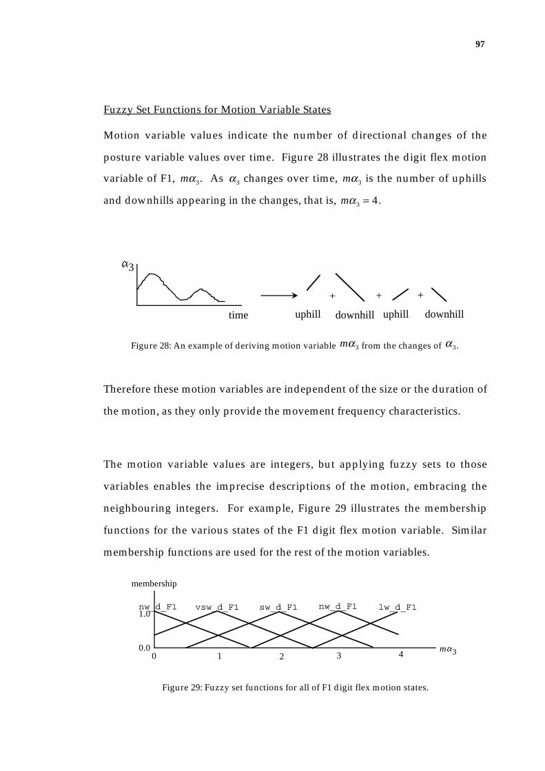
97
Fuzzy Set Functions for Motion Variable States
Motion variable values indicate the number of directional changes of the
posture variable values over time. Figure 28 illustrates the digit flex motion
variable of F1, mα3. As α3 changes over time, mα3 is the number of uphills
and downhills appearing in the changes, that is, mα3 = 4 .
time
a3
uphill downhill
+ + +
uphill downhill
Figure 28: An example of deriving motion variable mα3 from the changes of α3.
Therefore these motion variables are independent of the size or the duration of
the motion, as they only provide the movement frequency characteristics.
The motion variable values are integers, but applying fuzzy sets to those
variables enables the imprecise descriptions of the motion, embracing the
neighbouring integers. For example, Figure 29 illustrates the membership
functions for the various states of the F1 digit flex motion variable. Similar
membership functions are used for the rest of the motion variables.
0 0.0
1.0
membership
nw_d_F1
ma31 2 3 4
vsw_d_F1 sw_d_F1 nw_d_F1 lw_d_F1
Figure 29: Fuzzy set functions for all of F1 digit flex motion states.

98
Even though the vsw_d_F1 in F1 digit flex represents the motion value of 1
(that is, only one uphill or downhill shape is found in digit flex motion),
neighbouring integers such as 0 or 2 may be included in the range of the set,
ℜvsw_d_F1, but with smaller degrees of membership. This can be written as
f vsw_d_F1: ℜvsw_d_F1 → 0..1[ ], where mα3 ∈ℜvsw_d_F1 ,
and since mα3 is an integer in 0,1,2{ }, I define
f nw_d_F0(0) = 0.33,
f vsw_d_F0(1) = 1.0, and
fsw_d_F0(2) = 0.33.
4.3.3 Sign Representation
Using the motion variables and the posture definition, a sign is represented by
• A starting posture variable.
Its states may be an Auslan basic hand posture, for example,
posture_ten0, posture_spread0 etc.
• Motion variables.
• An ending posture variable.
Its states may be an Auslan basic hand posture.
Figure 30(a), (b) and (c) show examples of signs and their corresponding sign
representations that are used in the HMU system. A static sign, sign_hook
and two dynamic signs, sign_ten and sign_scissors are used as examples.

99
finger digit flex for F0 .. F4:fx_d_F0, fx_d_F1, fx_d_F2, fx_d_F3, fx_d_F4
knuckle flex for F1 .. F4:st_k_F1, fx_k_F2, fx_k_F3, fx_k_F4
finger spread:closed_FS
finger digit flex motion for F0 .. F4:nw_d_F0, nw_d_F1,nw_d_F2, nw_d_F3, nw_d_F4
finger knuckle flex motion for F1 .. F4:nw_k_F1, nw_k_F2, nw_k_F3, nw_k_F4
finger spread motionnw_FS
starting posture motion ending posture(AUSLAN basic hand shape posture_hook0) (AUSLAN basic hand shape posture_hook0)
finger digit flex for F0 .. F4:fx_d_F0, fx_d_F1, fx_d_F2, fx_d_F3, fx_d_F4
knuckle flex for F1 .. F4:st_k_F1, fx_k_F2, fx_k_F3, fx_k_F4
finger spread:closed_FS
Figure 30(a): Graphical description of a static sign, sign_hook and its sign representation.
finger digit flex for F0 .. F4:fx_d_F0, fx_d_F1, fx_d_F2, fx_d_F3, fx_d_F4
knuckle flex for F1 .. F4:fx_k_F1, fx_k_F2, fx_k_F3, fx_k_F4
finger spread:close_FS
finger digit flex motion for F0 .. F4:vsw_d_F0, vsw_d_F1, vsw_d_F2, vsw_d_F3, vsw_d_F4
finger knuckle flex motion for F1 .. F4:vsw_k_F1, vsw_k_F2, vsw_k_F3, vsw_k_F4
finger spread motionvsw_FS
finger digit flex for F0 .. F4:st_d_F0, st_d_F1, st_d_F2, st_d_F3, st_d_F4
knuckle flex for F1 .. F4:st_k_F1, st_k_F2, st_k_F3, st_k_F4
finger spread:spread_FS
starting posture motion ending posture(AUSLAN basic hand shape posture_ten0) (AUSLAN basic hand shape posture_spread0)
Figure 30(b): Graphical description of sign_ten and its sign representation.
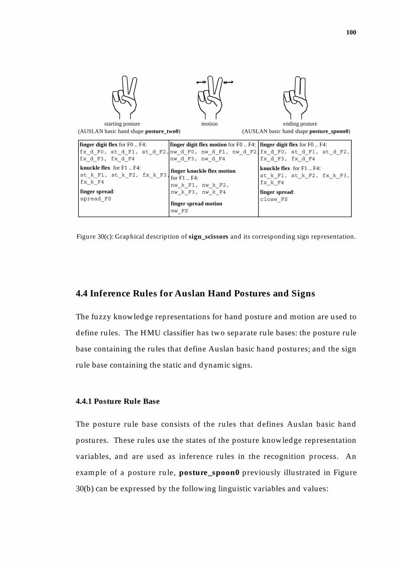
100
finger digit flex for F0 .. F4:fx_d_F0, st_d_F1, st_d_F2, fx_d_F3, fx_d_F4
knuckle flex for F1 .. F4:st_k_F1, st_k_F2, fx_k_F3, fx_k_F4
finger spread:spread_FS
finger digit flex motion for F0 .. F4:nw_d_F0, nw_d_F1, nw_d_F2, nw_d_F3, nw_d_F4
finger knuckle flex motion for F1 .. F4:nw_k_F1, nw_k_F2, nw_k_F3, nw_k_F4
finger spread motionmw_FS
finger digit flex for F0 .. F4:fx_d_F0, st_d_F1, st_d_F2, fx_d_F3, fx_d_F4
knuckle flex for F1 .. F4:st_k_F1, st_k_F2, fx_k_F3, fx_k_F4
finger spread:close_FS
starting posture motion ending posture(AUSLAN basic hand shape posture_two0) (AUSLAN basic hand shape posture_spoon0)
Figure 30(c): Graphical description of sign_scissors and its corresponding sign representation.
4.4 Inference Rules for Auslan Hand Postures and Signs
The fuzzy knowledge representations for hand posture and motion are used to
define rules. The HMU classifier has two separate rule bases: the posture rule
base containing the rules that define Auslan basic hand postures; and the sign
rule base containing the static and dynamic signs.
4.4.1 Posture Rule Base
The posture rule base consists of the rules that defines Auslan basic hand
postures. These rules use the states of the posture knowledge representation
variables, and are used as inference rules in the recognition process. An
example of a posture rule, posture_spoon0 previously illustrated in Figure
30(b) can be expressed by the following linguistic variables and values:
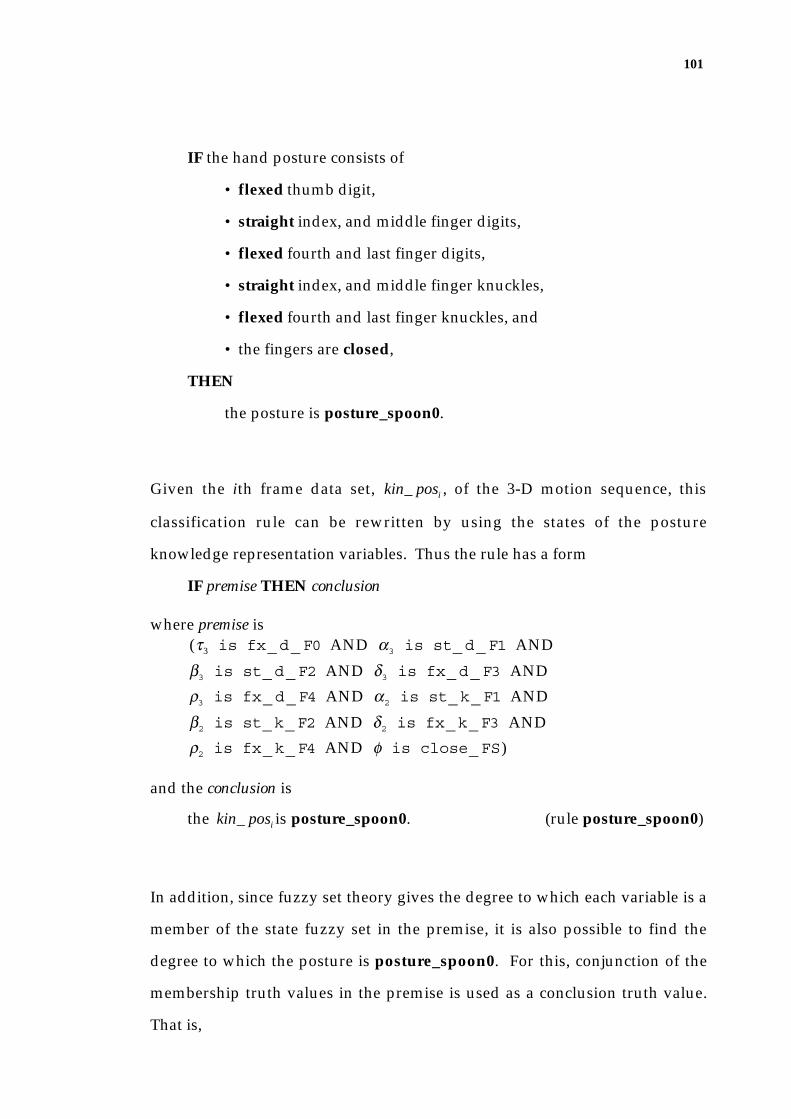
101
IF the hand posture consists of
• flexed thumb digit,
• straight index, and middle finger digits,
• flexed fourth and last finger digits,
• straight index, and middle finger knuckles,
• flexed fourth and last finger knuckles, and
• the fingers are closed,
THEN
the posture is posture_spoon0.
Given the ith frame data set, kin_ posi , of the 3-D motion sequence, this
classification rule can be rewritten by using the states of the posture
knowledge representation variables. Thus the rule has a form
IF premise THEN conclusion
where premise is
(τ3 is fx_d_F0 AND α3 is st_d_F1 AND
β3 is st_d_F2 AND δ3 is fx_d_F3 AND
ρ3 is fx_d_F4 AND α2 is st_k_F1 AND
β2 is st_k_F2 AND δ2 is fx_k_F3 AND
ρ2 is fx_k_F4 AND φ is close_FS)
and the conclusion is
the kin_ posi is posture_spoon0. (rule posture_spoon0)
In addition, since fuzzy set theory gives the degree to which each variable is a
member of the state fuzzy set in the premise, it is also possible to find the
degree to which the posture is posture_spoon0. For this, conjunction of the
membership truth values in the premise is used as a conclusion truth value.
That is,

102
f posture_spoon0 (kin_ posi )
= min( ffx_d_F0(τ3 ), fst_d_F1(α3 ), fst_d_F2(β3 ), ffx_d_F3(δ3 ),
ffx_d_F4(ρ3 ), fst_k_F1(α2 ), fst_k_F2(β2 ), ffx_k_F3(δ2 ),
ffx_k_F4(ρ2 ), fclose_FS(φ ))
4.4.2 Sign Knowledge Base
An example of a sign rule is as follows:
IF the signing movement consists of
• posture_two0 as a starting hand posture,
• no wiggle in the thumb flex movement,
• no wiggle in the index, middle, fourth, and last finger flex
movement,
• no wiggle in the index, middle, fourth, and the last finger knuckle
flex movement,
• medium wiggle in finger spreading,
• posture_spoon0 as an ending posture,
THEN
the sign is sign_scissors.
Illustrations of sign_scissors was previously shown in Figure 30(c). Assuming
that the input sequence kin_ seq contains the starting posture of the sign in the
ith frame, that is kin_ posi ; the ending posture in jth frame, kin_ posj ; and the
motion variables are defined to represent the posture changes from kin_ posi to
kin_ posj ; then the sign_scissors rule can be rewritten by using the defined
variables and states as follows.
103
IF
(kin_ posi is posture_ two0 AND
mτ3 is nw_d_F0 AND mα3 is nw_d_F1 AND
mβ3 is nw_d_F2 AND mδ3 is nw_d_F3 AND
mρ3 is nw_d_F4 AND mα2 is nw_k_F1 AND
mβ2 is nw_k_F2 AND mδ2 is nw_k_F3 AND
mρ2 is nw_k_F4 AND mφ is mw_FS AND
kin_ posj is posture_spoon0)
THEN
kin_ seq is sign_scissors. (rule sign_scissors)
As before, the degree to which the sign is sign_scissors is defined as
f sign_ ten (kin_ seq)
= min( f posture_ two0 (kin_ posi ),
f nw_d_F0(mτ3 ), f nw_d_F1(mα3 ), f nw_d_F2(mβ3 ), f vsw_d_F3(mδ3 ),
f nw_d_F4(mρ3 ), f nw_k_F1(mα2 ), f nw_k_F2(mβ2 ), f vsw_k_F3(mδ2 ),
f nw_k_F4(mρ2 ), f mw_FS(mφ ),
f posture_spoon0(kin_ posj ))
4.5 The Classification Process
The input sequence always starts with a specified posture, posture_flat0. The
hand then moves to the starting posture of the sign and performs the sign until
it reaches the ending posture of the sign. The classifier performs the sign
recognition through the following stages:
1. recognition of Auslan basic hand postures appearing in the sequence
by using a fuzzy inference engine;
2. extraction of the starting and ending hand postures from the posture
sequence, and determination of the motion that occurred in between; and

104
3. recognition of the sign by using a fuzzy inference engine.
For example, an input kinematic sequence representing the sign_scissors
would be classified by the following steps:
In the first classification phase, each frame of the input kinematic sequence is
recognised as postures such as posture_flat0, that is the specified initial hand
posture, posture_two0, and posture_spoon0. The second classification phase
analyses the recognised postures in order to determine the starting and ending
postures of the sign as well as the motion variable values. In the example,
posture_two0 is chosen as the starting posture, posture_spoon0 as the ending
posture, and the in-between motion is determine. Then the third phase uses
posture_two0 and posture_spoon0, along with the motion data, and classify
them as sign_scissors.
The following section explains the fuzzy inference engine that is used for
posture/sign recognition. The complete classification process of the kinematic
sequence into a sign is explained using the example of sign_scissors.
4.5.1. Fuzzy Inference Engine
Both the posture and sign recognition processes use a fuzzy inference engine
as shown in Figure 31.
The fuzzy inference engine recognises the posture/sign by:
• activating rules in the rule base; and
• determining the most likely posture/sign.

105
Input Kinematic Sequence
Fuzzy Inference Engine
Activation of rules
Determining Output
For each rule, determine if the input meets the conditions of the rule by using the fuzzy sets.
If the conditions are satisfied then the rule is fired, and the rule activation level is calculated by using the fuzzy set functions.
The rule with the highest activation level is chosen as the output.
Posture Classification
Motion Analysis
Sign Classification
Posture variablefuzzy set functions
Posturerule base
Motion variablefuzzy set functions
Sign rule base
Figure 31: Sign Classification using the fuzzy inference engine.
The fuzzy inference engine activates every rule in the rule base. Note that,
because of my representation, all rules have exactly the same number of
control variables in the premise, which consists of a single state for each
variable in the knowledge representation.
For each rule, the inference engine determines if the input satisfies the
conditions in the premise of the rule. If all conditions are satisfied, then the
rule is fired. In this process, the conjunction (that is the minimum) of the
corresponding membership truth values for each variable in that rule is kept as
a Rule Activation Level (namely, RAL). This RAL, in the range of 0..1[ ],
indicates confidence of the input being the posture or sign.
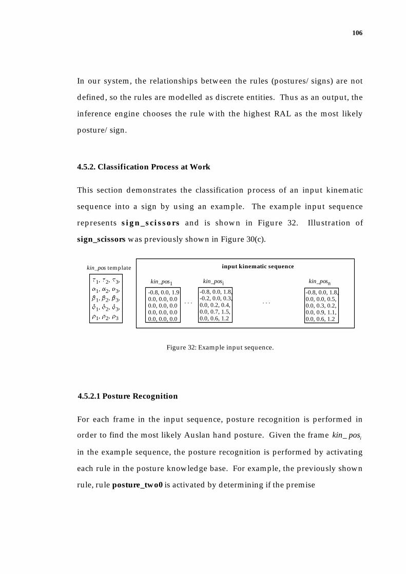
106
In our system, the relationships between the rules (postures/signs) are not
defined, so the rules are modelled as discrete entities. Thus as an output, the
inference engine chooses the rule with the highest RAL as the most likely
posture/sign.
4.5.2. Classification Process at Work
This section demonstrates the classification process of an input kinematic
sequence into a sign by using an example. The example input sequence
represents sign_scissors and is shown in Figure 32. Illustration of
sign_scissors was previously shown in Figure 30(c).
t1, t2, t3,
a1, a2, a3,b1, b2, b3,
d1, d2, d3,r1, r2, r3
kin_pos template
-0.8, 0.0, 1.90.0, 0.0, 0.00.0, 0.0, 0.00.0, 0.0, 0.00.0, 0.0, 0.0
-0.8, 0.0, 1.8,-0.2, 0.0, 0.3,0.0, 0.2, 0.4,0.0, 0.7, 1.5,0.0, 0.6, 1.2
. . . . . .
kin_pos1 kin_posi kin_posn
input kinematic sequence
-0.8, 0.0, 1.8,0.0, 0.0, 0.5,0.0, 0.3, 0.2,0.0, 0.9, 1.1,0.0, 0.6, 1.2
Figure 32: Example input sequence.
4.5.2.1 Posture Recognition
For each frame in the input sequence, posture recognition is performed in
order to find the most likely Auslan hand posture. Given the frame kin_ posi
in the example sequence, the posture recognition is performed by activating
each rule in the posture knowledge base. For example, the previously shown
rule, rule posture_two0 is activated by determining if the premise

107
(1.8 is fx_d_F0 AND 0.3 is st_d_F1 AND
0.4 is st_d_F2 AND 1.5 is fx_d_F3 AND
1.2 is fx_d_F4 AND 0.0 is st_k_F1 AND
0.2 is st_k_F2 AND 0.7 is fx_k_F3 AND
0.6 is fx_k_F4 AND 0.2 is spread_FS)
is true. The truthfulness of a condition such as “ 0.3 is st_d_F1“ is
determined by whether 0.3 is in the kinematic angle range for the fuzzy set
st_d_F1. This fuzzy set range was previous shown in Figure 24(b). Since
0.3 is within the range, the condition is satisfied.
In this example, all conditions are satisfied, thus the conclusion “ kin_ posi is
posture_two0” is true. The degree to which this conclusion is true (that is
RAL) is calculated by
f posture_ two0 (kin_ posi )
= min( ffx_d_F0(1.8), fst_d_F1(0.3), fst_d_F2(0.4), ffx_d_F3(1.5),
ffx_d_F4(1.2), fst_k_F1(0.0), fst_k_F2(0.2), ffx_k_F3(0.7),
ffx_k_F4(0.6), fspread_FS(0.2)).
The membership truth value of fst_d_F1(0.3) is shown in Figure 33.
a3(radians)0 1.5
0.0
1.0
membership
st_d_F1 fx_d_F1
0.2
0.8
0.3
Figure 33: Applying fuzzy set functions when F1 digit flex is 0.3.
Figure 33 also shows the overlap between the states sf_d_F1 and
cf_d_F1, and the input 80 degrees belonging to both states.

108
• 0.3 is st_d_F1 where fst_d_F1(0.3) = 0.8, and
• 0.3 is fx_d_F1 where ffx_d_F1(0.3) = 0.2.
Such fuzzy set overlaps may result in kin_ posi satisfying more than one posture
rule. If this is the case, the inference engine simply chooses the rule with the
highest RAL. Thus the posture recognition produces the posture that is
represented in the rule as posture output, with the RAL.
4.5.2.2 Analysis of the Posture Sequence
Once the posture classification is performed for each frame of the kinematic
sequence, the posture sequence is analysed to establish the sign knowledge
representation by determining the starting and ending postures and by
calculating the motion variables.
Starting and Ending Postures
The motion sequences always start with posture_flat0. The posture sequence
is therefore expected to contain this hand posture as the first posture
appearing in the sequence. The classifier observes the hand movement from
the neutral posture to determine whether any of the finger digit, knuckle or
finger spreading movement changes its direction. The posture which appears
just before the directional change of the movement, and which has a duration
of more than 4 consecutive frames in the sequence is chosen as a starting
posture. This process eliminates possible in-between postures from the neutral
posture to the starting posture. Among appearances of the starting posture,
the maximum RAL is chosen as the starting posture membership truth value.
This is because the sequence contains the postures reaching towards the actual

109
posture as well as moving away to another posture, that may still be
recognised as the starting posture, but with lesser RAL.
The last appearing posture with the duration of more than 4 frames is chosen
as the ending posture, and for the same reason as the starting posture, the
maximum RAL amongst the corresponding posture classification results is
used as the ending posture membership truth value in the sign classification
process.
Figure 34 shows the postures appearing in the kinematic sequence of
sign_scissors. Here, posture_two0 represented in kin_ posi , is chosen as the
starting posture, and posture_spoon0 appearing as the last posture
represented in kin_ posn in the sequence is chosen as the ending posture.
posture_flat0 posture_two0 posture_spoon0
. . . . . . . . . . . .
posture_two0 posture_spoon0
Figure 34: Postures appearing the kinematic sequence of sign_scissors.
Generating Motion Data
As explained earlier in section 4.3.2, the motion data indicates the number of
uphills and downhills in the changes of individual posture variables. Thus the
classifier analyses the postures appearing between the starting posture and the
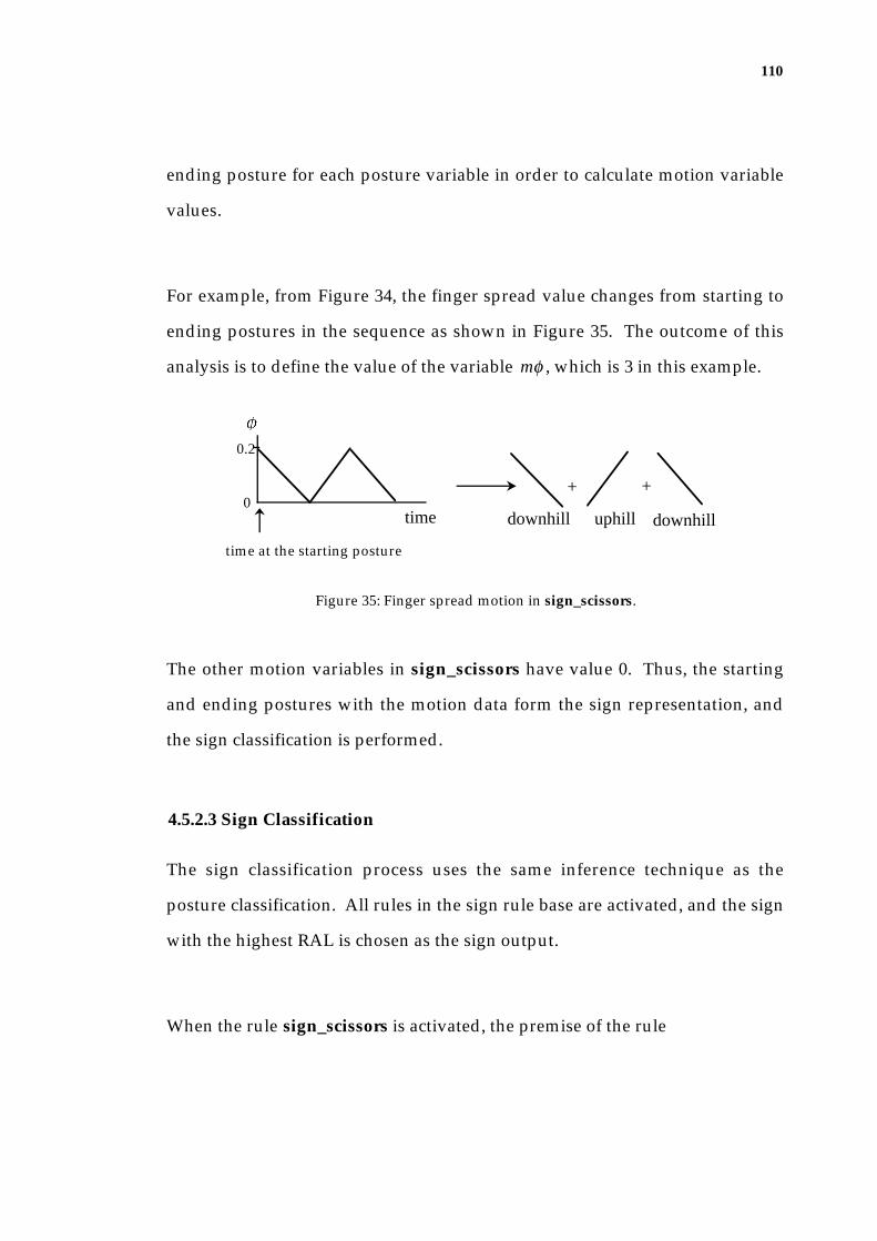
110
ending posture for each posture variable in order to calculate motion variable
values.
For example, from Figure 34, the finger spread value changes from starting to
ending postures in the sequence as shown in Figure 35. The outcome of this
analysis is to define the value of the variable mφ , which is 3 in this example.
time
f
downhill
+ +
uphill downhill
0.2
0
time at the starting posture
Figure 35: Finger spread motion in sign_scissors.
The other motion variables in sign_scissors have value 0. Thus, the starting
and ending postures with the motion data form the sign representation, and
the sign classification is performed.
4.5.2.3 Sign Classification
The sign classification process uses the same inference technique as the
posture classification. All rules in the sign rule base are activated, and the sign
with the highest RAL is chosen as the sign output.
When the rule sign_scissors is activated, the premise of the rule
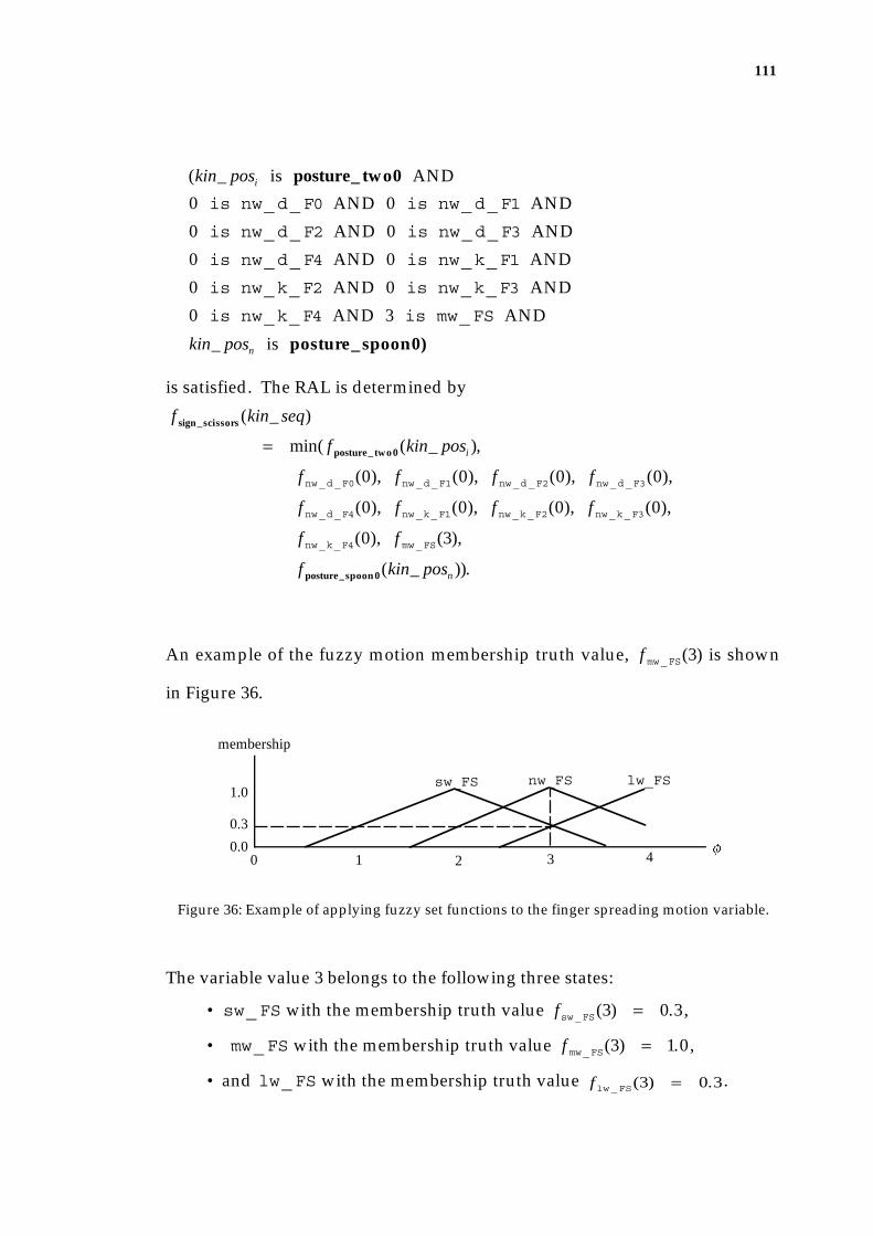
111
(kin_ posi is posture_ two0 AND
0 is nw_d_F0 AND 0 is nw_d_F1 AND
0 is nw_d_F2 AND 0 is nw_d_F3 AND
0 is nw_d_F4 AND 0 is nw_k_F1 AND
0 is nw_k_F2 AND 0 is nw_k_F3 AND
0 is nw_k_F4 AND 3 is mw_FS AND
kin_ posn is posture_spoon0)
is satisfied. The RAL is determined by
f sign_scissors(kin_ seq)
= min( f posture_ two0 (kin_ posi ),
f nw_d_F0(0), f nw_d_F1(0), f nw_d_F2(0), f nw_d_F3(0),
f nw_d_F4(0), f nw_k_F1(0), f nw_k_F2(0), f nw_k_F3(0),
f nw_k_F4(0), f mw_FS(3),
f posture_spoon0(kin_ posn )).
An example of the fuzzy motion membership truth value, f mw_FS(3) is shown
in Figure 36.
0 0.0
1.0
membership
f1 2 3 4
sw_FS nw_FS lw_FS
0.3
Figure 36: Example of applying fuzzy set functions to the finger spreading motion variable.
The variable value 3 belongs to the following three states:
• sw_FS with the membership truth value fsw_FS(3) = 0.3,
• mw_FS with the membership truth value f mw_FS(3) = 1.0 ,
• and lw_FS with the membership truth value flw_FS(3) = 0.3.

112
When all sign rules are activated, the result shows only one rule, sign_scissors
is fired, and thus is chosen as the output.
4.6 Adaptive Engine
The advantages of using the fuzzy expert system over a more conventional
expert system are not only that the rules can be expressed more naturally, but
also that noise in the input can be tolerated. However, the fuzzy expert system
may produce low decision confidence (RAL), or fail if the input lies close to or
outside the boundary of the fuzzy set. Thus, I decided to make our fuzzy
system adaptive.
Commonly practised adaptation techniques involve adjusting the weighting of
the rules (a multiplier that determines how much the output of each rule
affects the output fuzzy set) and dynamic adjustment of the "term set" (that is
the membership function) (Cox 1993).
The application of the weighting adjustment on the rules is not appropriate in
sign classification. This is because a weight on a rule implies a certain
importance of one sign over another, making some signs more likely than
others. Although this might be appropriate in some context-based signing
situations, I have decided to leave all signs with equal importance for the time
being.
In adaptive fuzzy systems, the modifications of fuzzy set regions are made by
slightly narrowing or widening the region depending upon whether the

113
system's response was above or below expectation, respectively (Cox 1993). In
the HMU classifier, dynamic adjustments to the individual fuzzy distributions
are performed under a supervised learning paradigm with individual signers.
As the training data are entered, the system classifies them into output signs
and their corresponding RALs. Then according to the output, the fuzzy
regions are modified. The training process of the fuzzy set functions through
the use of the adaptive engine is illustrated in Figure 37.
3-D Hand Tracker
Classifier
Output
Image Sequence
AaptiveEngine
posture variablefuzzy set functions
motion variablefuzzy set functions
Figure 37: Adaptive Engine.
The adaptive engine uses the following algorithm:
Suppose the output sign is k, with RAL µk , and Threshold denotes some
acceptable RAL level (typically 0.7 in our implementation).
IF (k is the expected output sign)
IF (µk > threshold )) THEN
/* Increase the decision confidence even higher. */

114
{Narrow all the fuzzy regions used to generate this output.}
ELSE /* µk ≤ threshold . */
{Widen the fuzzy regions that are responsible for the low RAL.}
ELSE (k is an unexpected sign) /* Wrong output is produced. */
IF (µk > threshold ) THEN
/* Attempt to reduce the decision confidence level. */
{Narrow the fuzzy regions that are responsible for this high
RAL.}
ELSE
{Do nothing.}
In our implementation, the size of the adjustment for fuzzy regions is given by
µk × factor or (1 − µk ) × factor in order to reduce or increase the width of the
region, where the factor is 0.1.
4.7 Summary
The HMU classifier recognises a sequence of 3-D hand kinematic data that is
attained by the tracker as a sign. This is achieved by using an adaptive fuzzy
expert system. Fuzzy set theory enables imprecise descriptions in the posture
and sign representation, and these representations are used to define rules of
inference for each posture and sign in the rule bases. The classification is
performed by
• firstly recognising Auslan basic hand postures appearing in each frame
of the kinematic sequence;
115
• secondly analysing the postures appearing throughout the sequence in
order to find the starting and ending postures of the sign, and the motion
in between; and
• thirdly recognising the starting and ending postures along with the
motion data as a sign.
Both the posture and sign recognition use a fuzzy inference engine that
activates every rule in the rule base to determine if the input is the
posture/sign represented in the rule. Once all rules are activated, the most
likely rule is chosen as the output.
The recognition performance largely depends on the fuzzy set regions that
define each of the posture/sign representation variable states. In order to find
the optimal fuzzy set regions for each of the defined states, an adaptive engine
that uses a supervised learning paradigm is devised.
116
Chapter 5
Experimental Results
The functionality of the HMU system is evaluated by observing the
recognition performance of static and dynamic signs. Given an image
sequence, the tracker generates the hand configuration with 21 degrees-of-
freedom for each frame of the sequence. The classifier recognises each hand
configuration as Auslan basic hand posture(s) and, by analysing the sequence
of postures that appears throughout the sequence, it recognises a sign.
The posture rule base consists of 22 postures that are a subset of Auslan basic
hand postures and their variants. The sign rule base consists of 22 signs,
including 11 static signs and 11 dynamic signs. They consist of some actual
Auslan signs as well as synthetic signs that use various combinations of the
basic hand postures and motion. The postures used in the system are
illustrated in Appendix A, and the posture and sign rules stored in the rule
bases are shown in Appendix B. A synthetic sign is named by using the
starting and ending hand postures used in the motion, such as
sign_good_spoon or sign_ambivalent , or by using the movement
characteristics along with the posture names used in the motion, such as
sign_queer_flicking, or sign_fist_bad.
117
5.1 Chapter Overview
The performance of the HMU system is tested by observing the recognition
process applied to sequences consisting of each of the 22 signs. The evaluation
includes the training process whereby the fuzzy set functions used in the
classifier are trained in order to improve the performance of the HMU system.
The performance evaluation is conducted prior to and after training.
In this chapter, the evaluation results are explained in detail in the following
sections:
• Section 5.2 explains the experimental details for the selection process of
the test and training data;
• Section 5.3 explains and discusses the recognition performances prior
to and after training;
• Section 5.4 reports the problems that were encountered in the
evaluation; and
• Section 5.5 concludes the chapter with a summary.
5.2 Experimental Details
5.2.1 Assumptions
Speed
The hand tracker is built with the assumption that, in an image sequence, the
maximum change of hand configuration from frame to frame is limited. As
explained in section 3.2.1, a closing hand motion should appear in about 6
consecutive frames in an image sequence. This assumption affected the

118
decision on the search window size in the marker detection algorithm in
section 3.5.2, by allowing a maximum of 20-30 degrees in a joint angle change
from frame to frame. It also affected the prediction algorithm (explained in
section 3.5.3.1) by using 6 previous hand configuration estimations for
prediction. Thus given the sequence grabbing speed of the hardware used
(that is 4-5 frames per second), the hand movement is performed slowly
during the sequence recording, so that closing the hand takes about 1.5
seconds.
Slight Delay at the Key Sign Postures
For all signs, the hand commences the movement from the specified initial
hand posture, posture_flat0. Then for a static sign, the hand moves to the
posture that represents that sign. As for a dynamic hand sign, the hand moves
to the starting posture of the sign, and continues the movement until it reaches
the sign's ending posture. In this chapter, the posture that represents a static
sign, or the starting and ending posture of a dynamic sign will be referred to as
a key sign posture. During the course of signing, a slight delay (about a second)
is enforced at a key sign posture in order to ensure that it appears in more than
4 frames. As explained in section 4.5.2.2, a posture needs to appear in at least 4
consecutive frames to be chosen as the posture appearing in the image.
5.2.2 Data Collection
One signer has participated in recording the image sequences, where she wore
the colour coded glove and performed signing under the fluorescent lighting
of a normal office environment. For evaluation, 44 motion sequences that
consist of two sub-sequences for each of the 22 signs, were recorded by using a

119
single video camera. To enable a fair test to be conducted, half of the recorded
sequences were used for testing, and the other half were used for training.
One sequence for each sign was randomly selected, producing the total of 22
sequences as a test set. The remaining 22 sequences were used as a training
set.
5.2.3 Selection of Training Data
The training was performed by the adaptive engine (in section 4.6) through
supervised learning. The adaptive engine modifies both the posture and
motion variable fuzzy set functions used for classification. Given a test
sequence, the posture recognition for each image frame and the sign
recognition for the whole sequence is performed. Based on the posture and
sign recognition results, the HMU system chooses the frames that are to be
used to train the posture variable fuzzy set functions (namely, posture
training), and uses the sign recognition result to train the motion variable
fuzzy set functions (namely, motion training).
A training motion sequence consists of frames that represent the initial hand
posture and the key sign postures, as well as the frames of their in-between
postures. In training the posture variable fuzzy set functions, the system
chooses the frames that represent the key sign postures of the expected sign.
During the process of recognition of the training sequence, some in-between
postures which are close in proximity to a key sign posture may be recognised
as the key sign posture, due to the nature of the fuzzy system that can
recognise the approximately similar postures. Thus, amongst the potentially
continuous appearances of the key sign posture, the frame that best represents

120
the key sign posture is likely be the one with the highest RAL, which will be
referred to as the key posture frame.
Therefore, for each key sign posture, the key posture frame, with two nearest
neighbouring frames in which the key sign posture is recognised, are chosen
for training of the posture variable fuzzy set functions. The neighbouring
frames are preferably the previous and the next frame to the key posture
frame. But in a case where the key posture frame is the last frame (this may
often be the case in a static sign posture, or the ending posture of the dynamic
sign), the two previous frames are chosen as neighbour frames. An example of
the training sequences, sign_hook and its recognition result is shown in Figure
38.
Note that in the sign recognition illustrations presented in this section, only
every third frame is shown.
In the sign_hook sequence, the key sign posture posture_hook0 is recognised
with the highest RAL in frame 25, the last frame of the sequence, thus frames
23, 24 and 25 are chosen for the training of posture_hook0. If the three
consecutive frames that represent the key sign posture do not exist in the
sequence, then the training for that key posture is not conducted. However,
training with the rest of the key sign posture (in the case of a dynamic sign) in
the same sequence must continue.
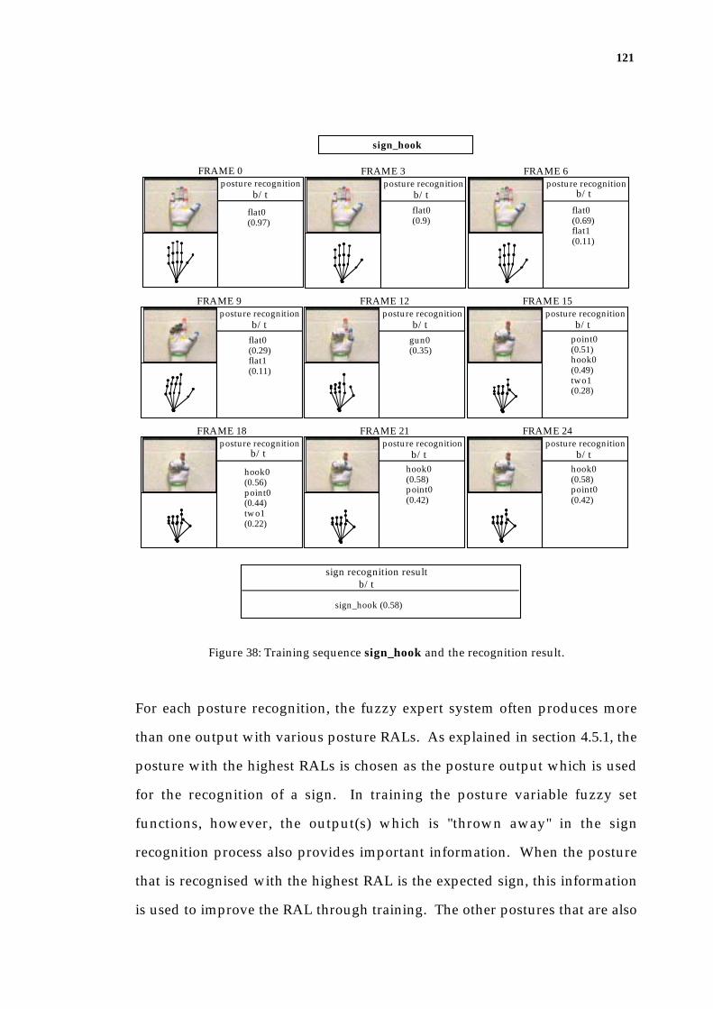
121
posture recognitionb/t
FRAME 0
sign_hook
sign recognition resultb/t
posture recognitionb/t
FRAME 3posture recognition
b/t
FRAME 6
posture recognitionb/t
FRAME 9posture recognition
b/t
FRAME 12posture recognition
b/t
FRAME 15
posture recognitionb/t
FRAME 18posture recognition
b/t
FRAME 21posture recognition
b/t
FRAME 24
flat0(0.9)
sign_hook (0.58)
flat0(0.97)
flat0(0.69)flat1(0.11)
flat0(0.29)flat1(0.11)
gun0(0.35)
point0(0.51)hook0(0.49)two1(0.28)
hook0(0.56)point0(0.44)two1(0.22)
hook0(0.58)point0(0.42)
hook0(0.58)point0(0.42)
Figure 38: Training sequence sign_hook and the recognition result.
For each posture recognition, the fuzzy expert system often produces more
than one output with various posture RALs. As explained in section 4.5.1, the
posture with the highest RALs is chosen as the posture output which is used
for the recognition of a sign. In training the posture variable fuzzy set
functions, however, the output(s) which is "thrown away" in the sign
recognition process also provides important information. When the posture
that is recognised with the highest RAL is the expected sign, this information
is used to improve the RAL through training. The other postures that are also

122
recognised provide a means to train the system to avoid this output by
separating the postures into more discrete entities. An example of this is the
frame 24 in Figure 38. Both of the results posture_hook0, and posture_point0
are used for posture training. The recognition result of posture_hook0 is used
as a correctly recognised case, and the result of posture_point0 is used as an
incorrectly recognised case.
The sign recognition process produces results based on the motion fuzzy set
membership of the motion data as well as the recognition result of the starting
and ending postures. This result is directly used for the training of motion
fuzzy set functions.
5.2.4 Experiment Methodology
The evaluation methodology consists of the following three stages:
1. The 22 test sequences (one for each of the 22 signs) are recognised in
the HMU system producing the results before training;
2. The 22 training sequences are used to train the fuzzy set functions
through the adaptive engine;
3. The test sequences are tested again to produce results after training by
using the modified fuzzy set functions in phase 2.
5.3 Results
Prior to training, the system correctly recognised 20 out of the 22 signs. After
training, for the same test set, the recognition rate is improved to recognise 21
signs. For all failed cases, the system did not produce any output. Figure 39
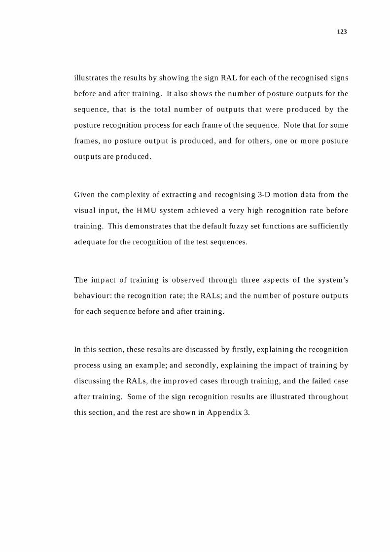
123
illustrates the results by showing the sign RAL for each of the recognised signs
before and after training. It also shows the number of posture outputs for the
sequence, that is the total number of outputs that were produced by the
posture recognition process for each frame of the sequence. Note that for some
frames, no posture output is produced, and for others, one or more posture
outputs are produced.
Given the complexity of extracting and recognising 3-D motion data from the
visual input, the HMU system achieved a very high recognition rate before
training. This demonstrates that the default fuzzy set functions are sufficiently
adequate for the recognition of the test sequences.
The impact of training is observed through three aspects of the system's
behaviour: the recognition rate; the RALs; and the number of posture outputs
for each sequence before and after training.
In this section, these results are discussed by firstly, explaining the recognition
process using an example; and secondly, explaining the impact of training by
discussing the RALs, the improved cases through training, and the failed case
after training. Some of the sign recognition results are illustrated throughout
this section, and the rest are shown in Appendix 3.

124
signRALsuccess success RAL
before training after training
ambivalentdarkdewfist_badflickingfourgoodgood_animalgood_spoongunhavehookokpointqueerqueer_flickingquotescissorsspoonspreadtentwo
0.450.710.50.370.270.810.83
0.710.630.580.710.790.510.460.410.630.80.580.320.82
0.450.710.50.280.260.80.830.60.580.710.630.580.710.790.510.460.41
0.80.530.320.82
no. of pos.outputs
37247838343833(41)*(63)*13544740872711896205*19674919
3721673632383236*56*1353472681168379(193)*19674415
22
number of signs number of sequences per sign
1
total numberof test sequence
22
beforetraining
aftertraining
number of success 21
succes rate (%) 91 95
20
ave. reduction rate for the posture outputs after training (%) 10.7
RECOGNITION RESULTS
no. of pos.outputs
Figure 39: Evaluation Results. A tick in the 'success' column indicates that the sign is
recognised correctly, and a dash indicates that no output is produced. An asterisk in
the 'no. of pos. outputs' column indicates the figure that is not included in calculating
the average reduction rate for the posture outputs after training (only the signs that
were recognised before and after training are used for the calculation).

125
5.3.1 Recognition Process
The recognition process of sign_ten before and after training is shown in
Figure 40 (sign_ten was previously illustrated in Figure 30(b)). For each
frame, the tracker recovers a 3-D hand configuration with 21 degrees-of-
freedom as illustrated under the image in the figure. If the measured features
are accurate enough (which means there exists a model configuration that very
closely fits the posture appearing in the image), even for a large angle change,
the tracker effectively converges to the solution in one or two iterations.
Otherwise, 20 iterations are performed and the best fitting cycle is chosen as a
solution, as explained in section 3.6.9. The posture classification process
recognises the tracker result as an Auslan basic hand posture(s). In Figure 40,
the training result before training (b/t) and after training (a/t) are shown, and
each posture output is accompanied by a posture RAL. NF represents that no
output is found.
The figure shows that approximately similar postures are successfully
recognised for each of the frames. The posture with the highest RAL is chosen
for each frame towards the sign recognition. After training, the postures that
appeared in the sequence are
• posture_flat0 in frames from 0 to 3;
• NF in frames 4;
• posture_good0 in frame 5;
• posture_good1 in frames 6 to 7;
• posture_ten0 in frames 8 to 12;
• NF in frames 13 to 15;
• posture_four0 in frames 16 to 17;
• posture_flat1 in frames 18 to 20;
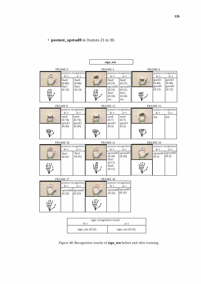
126
• posture_spread0 in frames 21 to 30.
posture recognitionb/t a/t
FRAME 0
sign_ten
sign recognition resultb/t a/t
posture recognitionb/t a/t
FRAME 3posture recognition
b/t a/t
FRAME 6
posture recognitionb/t a/t
FRAME 9posture recognition
b/t a/t
FRAME 12posture recognition
b/t a/t
FRAME 15
posture recognitionb/t a/t
FRAME 18posture recognition
b/t a/t
FRAME 21posture recognition
b/t a/t
FRAME 24
posture recognitionb/t a/t
FRAME 27posture recognition
b/t a/t
FRAME 30
flat0(0.86)flat1(0.13)
flat0(0.86)flat1(0.13)
flat0(0.23)spread0(0.23)flat1(0.16)etc.
flat0(0.21)spread0(0.21)flat1(0.16)etc.
good1(0.44)good0(0.15)
good1(0.44)good0(0.15)
ten0(0.74)good1(0.26)
ten0(0.74)good1(0.26)
ten0(0.7)good1(0.3)
ten0(0.7)good1(0.3)
NF NF
flat1(0.41)
flat1(0.41)
spread0(0.26)flat1(0.11)flat0(0.11)
spread0(0.26)
spread0(0.3)
spread0(0.3)
spread0(0.32)
spread0(0.32)
spread0(0.32)
spread0(0.32)
sign_ten (0.32) sign_ten (0.32)
Figure 40: Recognition results of sign_ten before and after training.

127
The thresholding of this posture list finds only the posture that appears in
more than 4 consecutive frames. Thus, the starting posture posture_ten0 and
the ending posture posture_spread0 are determined and the motion
parameters are calculated, and finally sign_ten is recognised.
5.3.2 Impact of Training
The adaptive engine in the HMU system aims to modify the fuzzy set
functions in order to improve the system's behaviour. The adjustment of a
fuzzy set region may result in one of the three following states: widened,
narrowed or unchanged. The changes of fuzzy set regions indicate the
changes in the size of the acceptable fuzzy domain of the corresponding
variable. In other words, for a narrowed region, the allowed difference
between the input variable value attained from the image and the absolutely
correct variable value that is defined in the system, is reduced. For a widened
region, the allowed difference is increased. Therefore, in the example of
posture recognition, the narrowing of the posture variable fuzzy regions
implies that the system is becoming more selective when classifying the input
data, by further separating the posture from others in the rule base and
making them more distinct. Furthermore, the narrowing of the regions
increases the fuzzy membership truth value for variable values within the
range. Since the minimum fuzzy membership truth value is selected as the
RAL, if the fuzzy set region that was responsible for the RAL before training is
narrowed through training, and provided that other fuzzy set regions used in
the posture rule are not widened, the RAL should improve after training.
Widening of the fuzzy regions, on the other hand, results in the system
becoming less selective and reduces the RALs, but may be necessary to
recognise the posture and signs that were not recognised before training.
128
Thus the effective training should make appropriate adjustments to all fuzzy
set regions in order to achieve an improved recognition rate, higher RALs, as
well as producing fewer posture outputs for each sequence. The results in
Figure 39 show that the training in the HMU system provided only a minor
impact on the recognition rate by recognising only one additional sign. Two
signs (sign_good_spoon and sign_good_animal) that were not recognised
before training are successfully recognised after training. But one sign
(sign_scissors) that was recognised before training is not recognised after
training. While the training did not improve the RALs, it made an impact on
reducing the number of posture outputs for many of the sequences, without
affecting the overall recognition result. For the signs that are recognised before
and after training, the number of posture outputs is reduced by an average of
10.7% (range from 0% to 40.7%).
5.3.2.1 The Lower Rule Activation Levels (RALs) After Training
After training, the RALs of the recognised signs have not been improved from
the corresponding RALs before training. For some signs, they have even
deteriorated. A close observation shows that this is due to the rather large
range of errors the tracker generates for the same configuration in various
motion sequences. For example, for a visually obvious finger configuration
such as a straight finger, the tracker generates significant errors (up to 0.8) for
either the MCP or the PIP joint flex angles. For recognition of the postures, the
MCP flex angle is used for the knuckle flex, and the PIP joint angle is
independently used for the digit flex. Thus the accumulation of these errors
does not affect the PIP joint flex angle more than the MCP flex angle.

129
The errors may be caused due to the following reasons:
• anatomical construction and flexibility of the signer's hand, that cause
slight variation of the posture from what is intended;
• different degrees of difficulty among signs, some postures being more
difficulty to perform by the signer, thus producing larger errors;
• mislocations of the joint in an image due to noise and shadow, which
can cause rather significant errors in the tracker result. This is because
the finger segments are short and the markers are relatively large. Thus a
slight mislocation of a joint results in quite a significant tracker error as
illustrated in Figure 41.
actual jointlocations
measured joint locations
The TIP joint marker
The PIP joint marker
side viewingof the finger segment configuration
actual configuration
tracking result configurationbased on the measured joint locations
Figure 41: Slight mislocation of the joints, causing significant tracker error.
The Changes of Fuzzy Set Functions Through Training
During the course of training, widths of some fuzzy sets converged to a certain
size, whilst many of the fuzzy set region widths gradually converged to the
maximum region sizes that were enforced. Even though the adaptation
process is aimed at locally maximising the confidence level of the correct
output, the large range of errors which the tracker produces causes many of
the fuzzy set region widths to continuously expand, thus the RALs of the
recognised signs have not improved through training.
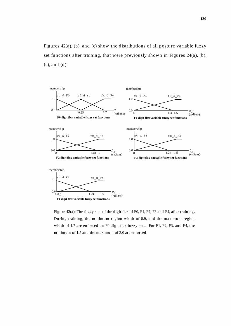
130
Figures 42(a), (b), and (c) show the distributions of all posture variable fuzzy
set functions after training, that were previously shown in Figures 24(a), (b),
(c), and (d).
a3(radians)0 1.5
0.0
1.0
membership
st_d_F1 fx_d_F1
F1 digit flex variable fuzzy set functions
1.39
b3(radians)0 1.5
0.0
1.0
membership
st_d_F2 fx_d_F2
F2 digit flex variable fuzzy set functions
1.48
t3(radians)0
0.0
1.0
membership
st_d_F0
0.85
fx_d_F0
1.7
sf_d_F0
F0 digit flex variable fuzzy set functions
d3(radians)0 1.5
0.0
1.0
membership
st_d_F3 fx_d_F3
F3 digit flex variable fuzzy set functions
1.24
r3(radians)0 1.5
0.0
1.0
membership
st_d_F4 fx_d_F4
F4 digit flex variable fuzzy set functions
1.240.6
Figure 42(a): The fuzzy sets of the digit flex of F0, F1, F2, F3 and F4, after training.
During training, the minimum region width of 0.9, and the maximum region
width of 1.7 are enforced on F0 digit flex fuzzy sets. For F1, F2, F3, and F4, the
minimum of 1.5 and the maximum of 3.0 are enforced.

131
a2(radians)0 0.9
0.0
1.0
membership
st_k_F1 fx_k_F1
F1 knuckle flex fuzzy set functions
0.88b2(radians)0 0.9
0.0
1.0
membership
st_k_F2 fx_k_F2
F2 knuckle flex fuzzy set functions
0.880.02
r2(radians)0 0.9
0.0
1.0
membership
st_k_F3 fx_k_F3
F3 knuckle flex fuzzy set functions
0.790.03 r2(radians)0 0.9
0.0
1.0
membership
st_k_F4 fx_k_F4
F4 knuckle flex fuzzy set functions
Figure 42(b): The fuzzy sets of the knuckle flex of F1, F2, F3 and F4, after training.
During training, the minimum region width of 1.0 and the maximum region
width of 1.8 are enforced to all of the knuckle flex fuzzy sets.
f
(radians)0 0.30.0
1.0
membership
closed_FS spread_FS
finger spread variable fuzzy set functions0.260.03
Figure 42(c): The fuzzy sets of the finger flex variable states, after training. During
training, the minimum region width of 0.4 and the maximum region width of 0.6 are
enforced.
Figure 43 shows some examples of the changes of posture variable fuzzy set
widths during training. During training, the function width of st_d_F3
gradually converged into 2.47, and the function width of st_d_F4 converged
into 2.48. The function width of fx_d_F3, on the other hand, stayed at the
maximum, 3.0 that was enforced during training.
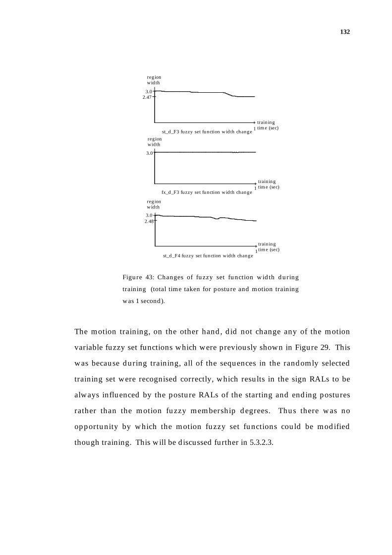
132
training time (sec)
regionwidth
3.02.47
1st_d_F3 fuzzy set function width change
region width
training time (sec)1
fx_d_F3 fuzzy set function width change
3.0
region width
st_d_F4 fuzzy set function width change1
training time (sec)
2.483.0
Figure 43: Changes of fuzzy set function width during
training (total time taken for posture and motion training
was 1 second).
The motion training, on the other hand, did not change any of the motion
variable fuzzy set functions which were previously shown in Figure 29. This
was because during training, all of the sequences in the randomly selected
training set were recognised correctly, which results in the sign RALs to be
always influenced by the posture RALs of the starting and ending postures
rather than the motion fuzzy membership degrees. Thus there was no
opportunity by which the motion fuzzy set functions could be modified
though training. This will be discussed further in 5.3.2.3.

133
5.3.2.2 The Examples of Improved Recognition Through Training
Even though the training of fuzzy set functions has not improved the RALs,
the results show that the system successfully recognises sign_good_animal
and sign_good_spoon, which were not recognised before training. This is
because whilst many of the fuzzy set functions stay at the maximum fuzzy set
regions, there are some regions that are narrowed, as shown in Figures 42 (a),
(b) and (c). Considering the average reduction rate of 10.7% for the posture
outputs after training (shown in Figure 39), it seems that this narrowing of the
regions has an impact on the system being more selective in recognition, by
reducing the difference between the input data from the image and the defined
posture that is recognised. The following cases explain this.
The result of sign_good_spoon is shown in Figure 44. Before training, the
postures from frames 20 and 26 are recognised as posture_ambivalent0, a
posture that is similar to the posture appearing in the image. This caused the
recognised sign motion to start from posture_good0, followed by
posture_ambivalent0, and ending with posture_spoon0. Even though the
starting posture posture_good0 and the ending posture posture_spoon0 are
correctly recognised, the HMU system fails to recognise sign_good_spoon,
because of two motion parameters, the number of wiggles of the last finger
motion involved, and the motion of the finger spread.
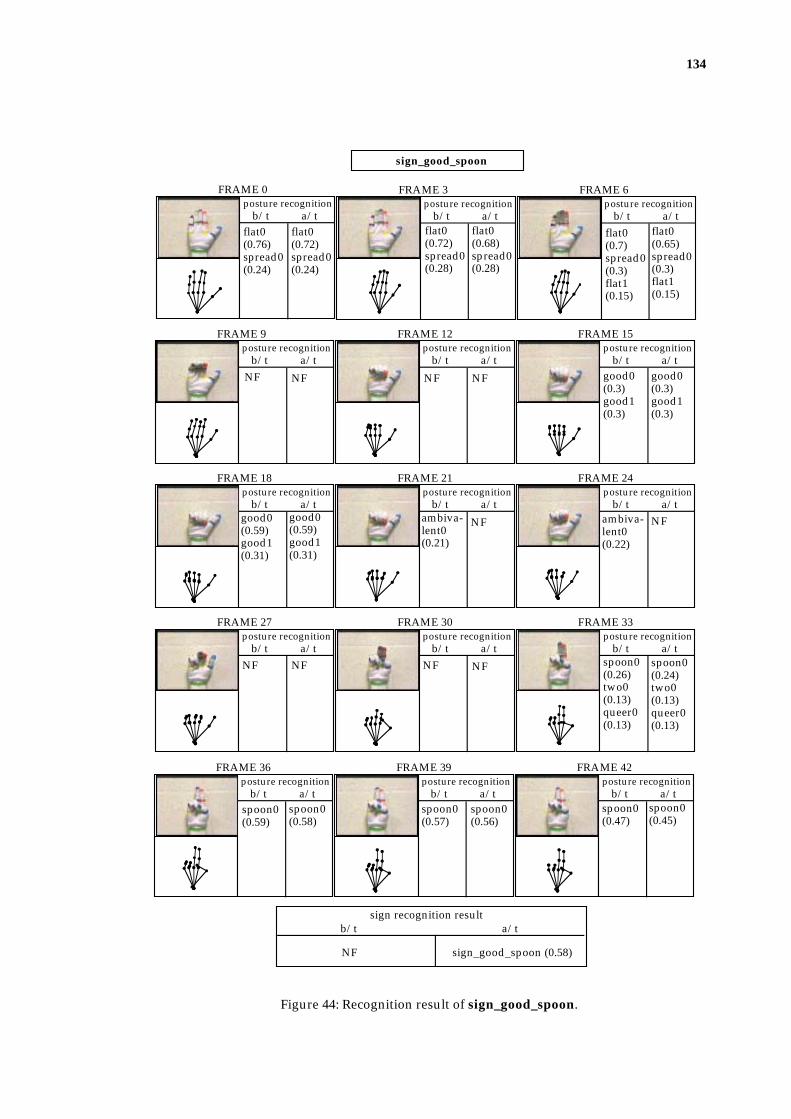
134
posture recognitionb/t a/t
FRAME 0
sign_good_spoon
sign recognition resultb/t a/t
posture recognitionb/t a/t
FRAME 3posture recognition
b/t a/t
FRAME 6
posture recognitionb/t a/t
FRAME 9posture recognition
b/t a/t
FRAME 12posture recognition
b/t a/t
FRAME 15
posture recognitionb/t a/t
FRAME 18posture recognition
b/t a/t
FRAME 21posture recognition
b/t a/t
FRAME 24
posture recognitionb/t a/t
FRAME 27posture recognition
b/t a/t
FRAME 30posture recognition
b/t a/t
FRAME 33
posture recognitionb/t a/t
FRAME 36posture recognition
b/t a/t
FRAME 39posture recognition
b/t a/t
FRAME 42
flat0(0.76)spread0(0.24)
flat0(0.72)spread0(0.24)
flat0(0.72)spread0(0.28)
flat0(0.68)spread0(0.28)
flat0(0.7)spread0(0.3)flat1(0.15)
flat0(0.65)spread0(0.3)flat1(0.15)
NF NF NF NF good0(0.3)good1(0.3)
good0(0.3)good1(0.3)
good0(0.59)good1(0.31)
good0(0.59)good1(0.31)
ambiva-lent0(0.21)
NF ambiva-lent0(0.22)
NF
NF NF NF NF spoon0(0.26)two0(0.13)queer0(0.13)
spoon0(0.24)two0(0.13)queer0(0.13)
spoon0(0.59)
spoon0(0.58)
spoon0(0.57)
spoon0(0.56)
spoon0(0.47)
spoon0(0.45)
NF sign_good_spoon (0.58)
Figure 44: Recognition result of sign_good_spoon.

135
Figure 45 compares the motion parameters that are calculated in the motion
consisting of posture_good0 - posture_ambivalent0 - posture_spoon0, before
training, and the motion parameters in the actual sign motion, posture_good0
- posture_spoon0.
posture_good0 posture_ambivalent0 posture_spoon0 posture_good0 posture_spoon0
motion_A motion_B
digit flex motion knuckle flex motion finger spread motionF0 F1 F1F2 F2F3 F3F4 F4
motion_A
motion_B
1 1
1 1 1 0 0 1 1 0 0 0
1 1 0 2 21 0 2
Figure 45: Motion parameters produced in sign_good_spoon before and after training.
After training, however, posture_ambivalent0 is not recognised in the frames
where it was recognised before training. Thus the motion from posture_good0
- posture_spoon0 is correctly recognised.
A similar situation occurred in sign_good_animal, where an in-between
posture that caused the motion parameter errors before training, was not
recognised after training.
The argument that the training has made postures more distinct is further
supported by observing other results illustrated in Appendix C. In the frames
of various sequences, the number of postures that were recognised after
training is often less than the number of recognised postures before training,
without affecting the overall recognition result.
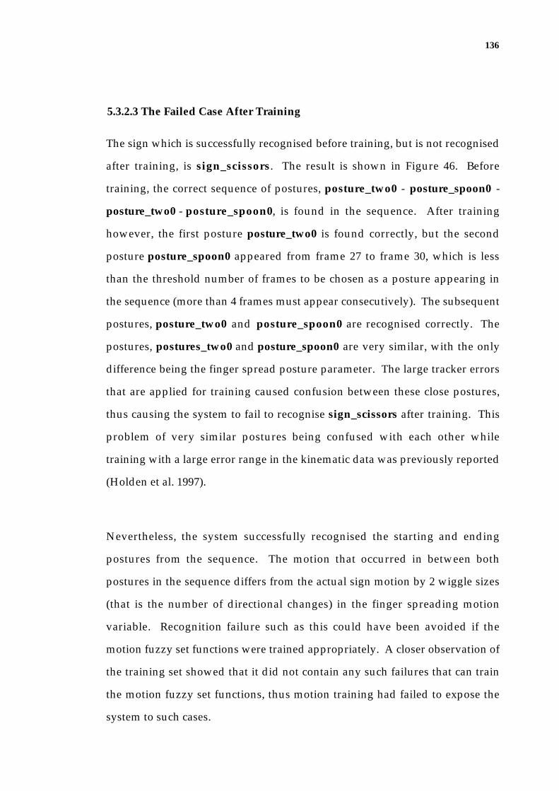
136
5.3.2.3 The Failed Case After Training
The sign which is successfully recognised before training, but is not recognised
after training, is sign_scissors. The result is shown in Figure 46. Before
training, the correct sequence of postures, posture_two0 - posture_spoon0 -
posture_two0 - posture_spoon0, is found in the sequence. After training
however, the first posture posture_two0 is found correctly, but the second
posture posture_spoon0 appeared from frame 27 to frame 30, which is less
than the threshold number of frames to be chosen as a posture appearing in
the sequence (more than 4 frames must appear consecutively). The subsequent
postures, posture_two0 and posture_spoon0 are recognised correctly. The
postures, postures_two0 and posture_spoon0 are very similar, with the only
difference being the finger spread posture parameter. The large tracker errors
that are applied for training caused confusion between these close postures,
thus causing the system to fail to recognise sign_scissors after training. This
problem of very similar postures being confused with each other while
training with a large error range in the kinematic data was previously reported
(Holden et al. 1997).
Nevertheless, the system successfully recognised the starting and ending
postures from the sequence. The motion that occurred in between both
postures in the sequence differs from the actual sign motion by 2 wiggle sizes
(that is the number of directional changes) in the finger spreading motion
variable. Recognition failure such as this could have been avoided if the
motion fuzzy set functions were trained appropriately. A closer observation of
the training set showed that it did not contain any such failures that can train
the motion fuzzy set functions, thus motion training had failed to expose the
system to such cases.

137
posture recognitionb/t a/t
FRAME 0
sign_scissors
sign recognition resultb/t a/t
posture recognitionb/t a/t
FRAME 6posture recognition
b/t a/t
FRAME 9
posture recognitionb/t a/t
FRAME 12posture recognition
b/t a/t
FRAME 15posture recognition
b/t a/t
FRAME 18
posture recognitionb/t a/t
FRAME 21posture recognition
b/t a/t
FRAME 24posture recognition
b/t a/t
FRAME 27
posture recognitionb/t a/t
FRAME 30posture recognition
b/t a/t
FRAME 33posture recognition
b/t a/t
FRAME 36
posture recognitionb/t a/t
FRAME 39posture recognition
b/t a/t
FRAME 42posture recognition
b/t a/t
FRAME 45
flat0(0.77)spread0(0.23)flat0(0.1)
flat0(0.73)spread0(0.23)flat1(0.1)
flat0(0.67)spread0(0.29)flat1(0.13)
flat0(0.72)spread0(0.29)flat1(0.13)
flat0(0.71)spread0(0.29)flat1(0.13)
flat0(0.67)spread0(0.29)flat1(0.13)
flat0(0.2)flat1(0.2)spread0(0.2)
NF NF NF two0(0.26)spoon0(0.1)point0(0.1)
two0(0.26)
two0(0.36)
two0(0.36)
two0(0.61)queer0(0.18)
two0(0.61)
spoon0(0.6)two0(0.4)queer0(0.26)etc.
spoon00.54)two0(0.4)two1(0.25)etc.
spoon0(0.62)two0(0.38)queer0(0.28)etc.
spoon0(0.56)two0(0.38)point0(0.2)etc.
two0(0.63)spoon0(0.37)queer0(0.28)etc.
two0(0.63)spoon0(0.27)two1(0.2)etc.
two0(0.69)queer0(0.26)two1(0.18)etc.
two0(0.66)two1().18)queer0(0.1)etc.
two0(0.68)queer0(0.26)two1(0.16)
two0(0.66)two1(0.16)queer0(0.11)
spoon0(0.66)two0(0.27)queer0(0.26)etc.
spoon0(0.65)two0(0.27)point0(0.12)etc.
spoon0(0.64)two0(0.14)queer0(0.14)etc.
spoon0(0.64)two0(0.14)poin0(0.12)etc.
sign_scissors (0.63) NF
Figure 46: The recognition result of sign_scissors.

138
5.4 Limitations
Within the extraction and classification of 21 degrees-of-freedom of the hand,
there are two types of information with which the HMU system has not been
fully tested in this evaluation: palm rotation, and trajectory motion.
5.4.1 Palm Rotation
The sign rule base consists of signs that do not use any extensive rotation of
the wrist, except sign_point. This is because the marker extraction process of
the tracker detects a sudden change of the palm marker sizes as a partial
occlusion, and predicts the partially missing marker locations instead of using
the measured locations. The roll and pitch rotation of the wrist may cause
significant changes of the palm marker areas, which would be considered as
an occlusion. Therefore, the rotated palm marker locations would not be
detected in the feature extraction process. To solve this problem, a better
marking scheme for the palm markers, or a method whereby the system can
distinguish between partial occlusion and rotation needs to be devised.
Nevertheless, the yaw movement of the wrist is well handled by the system, as
shown in Figure 47. As the hand rotates, the tracker accurately places the
palm and correctly fits the model.
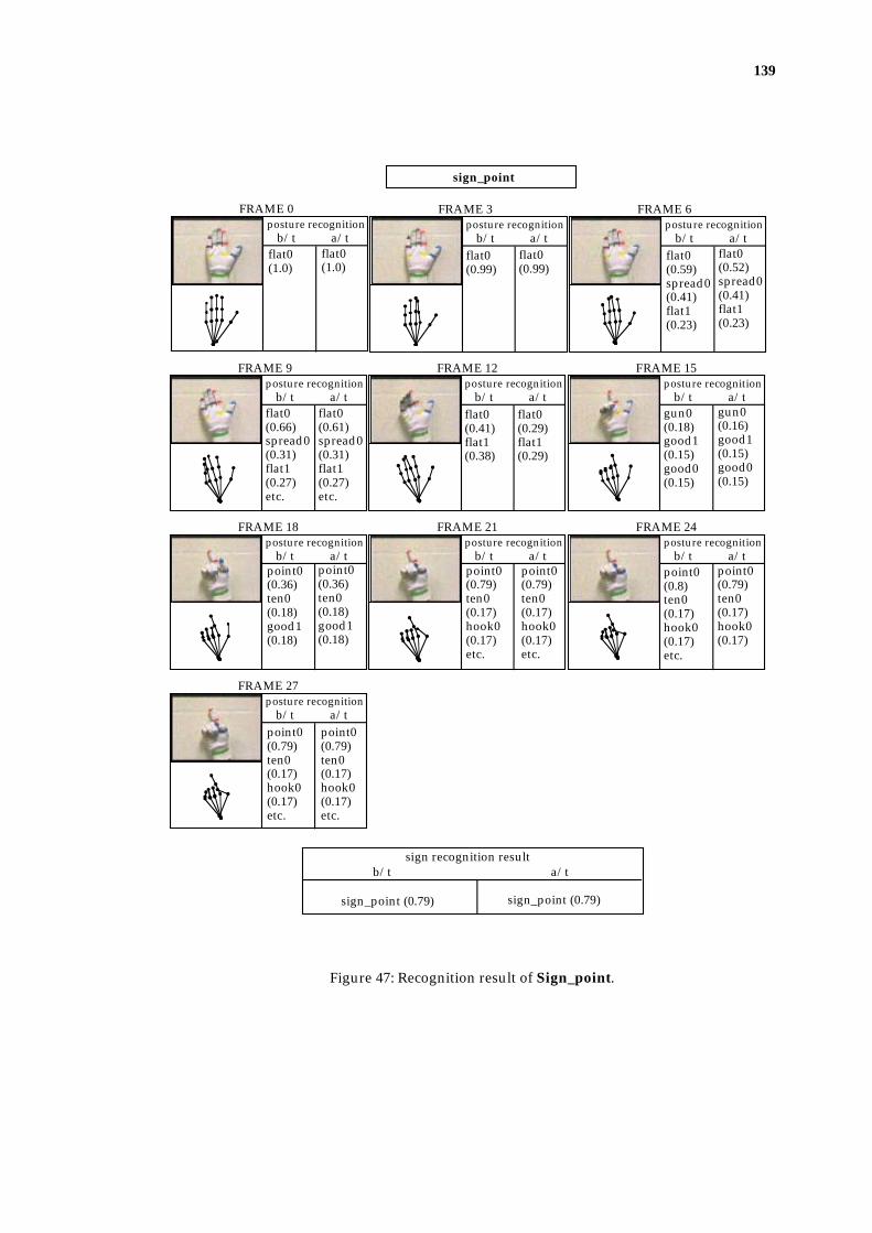
139
posture recognitionb/t a/t
FRAME 0
sign_point
sign recognition resultb/t a/t
posture recognitionb/t a/t
FRAME 3posture recognition
b/t a/t
FRAME 6
posture recognitionb/t a/t
FRAME 9posture recognition
b/t a/t
FRAME 12posture recognition
b/t a/t
FRAME 15
posture recognitionb/t a/t
FRAME 18posture recognition
b/t a/t
FRAME 21posture recognition
b/t a/t
FRAME 24
posture recognitionb/t a/t
FRAME 27
flat0(1.0)
flat0(1.0)
flat0(0.99)
flat0(0.99)
flat0(0.59)spread0(0.41)flat1(0.23)
flat0(0.52)spread0(0.41)flat1(0.23)
flat0(0.66)spread0(0.31)flat1(0.27)etc.
flat0(0.61)spread0(0.31)flat1(0.27)etc.
flat0(0.41)flat1(0.38)
flat0(0.29)flat1(0.29)
gun0(0.18)good1(0.15)good0(0.15)
gun0(0.16)good1(0.15)good0(0.15)
point0(0.79)ten0(0.17)hook0(0.17)etc.
point0(0.79)ten0(0.17)hook0(0.17)etc.
point0(0.8)ten0(0.17)hook0(0.17)etc.
point0(0.79)ten0(0.17)hook0(0.17)
point0(0.79)ten0(0.17)hook0(0.17)etc.
point0(0.79)ten0(0.17)hook0(0.17)etc.
sign_point (0.79) sign_point (0.79)
point0(0.36)ten0(0.18)good1(0.18)
point0(0.36)ten0(0.18)good1(0.18)
Figure 47: Recognition result of Sign_point.

140
5.4.2 Motion
The motion variables contain only the motion frequency information of the
finger digit and knuckle flex, and the finger spreading. Thus the signs used in
the evaluation do not rely on the trajectory of the hand, such as circular
motion, etc. even though the tracker is capable of effectively tracking the hand
translations in the sequences. This is because of the limited information the
current motion variables are capable of containing. A motion variable needs to
be extended in order to incorporate the signs that use various trajectory
motion into the dictionary.
5.5 Summary
The evaluation was conducted with 22 signs before and after training the
posture and motion variable fuzzy set functions used in the classifier. A total
of 44 sequences (two for each of the 22 signs) were recorded for the evaluation.
Among these a randomly selected set of 22 sequences was used for training,
and the remaining 22 sequences were used for testing.
Prior to training, 20 signs were recognised correctly, while for the two failed
cases, the system did not produce any output. Both of the two failures were
caused by the appearance of an unexpected posture in between the key sign
postures. The training of the fuzzy set functions has resulted in separating the
postures and making them more distinct, which in turn resulted in the
disappearance of the unexpected postures in the failed cases before training.
These signs were then correctly recognised after training. For the test after
training, 21 signs out of the 22 signs were recognised. The failed case used two

141
very similar postures, and the large errors that were generated by the tracker
confused these postures during training.
In the evaluation, however, the HMU system was not fully tested with the roll
and pitch rotations of the wrist, because of the fragility in locating the palm
markers. In addition, the randomly selected training set did not contain
sufficient errors in the motion variables, and thus I was not able to expose and
train the system for the possible motion errors.
142
Chapter 6
Conclusion
6.1 Summary
This thesis has presented a frame work of the vision based Hand Movement
Understanding (HMU) system. The HMU system recognises a static or
dynamic Auslan hand sign from a sequence of images. The system has two
modules:
• a model based 3-D hand tracker that recovers the 21 degree-of-freedom
parameters of the 3-D hand model, in order to fit the model to the hand
configuration captured in the image; and
• the classifier that recognises the sequence of 3-D hand model
configuration data as a sign.
The tracker consists of three major components: the hand model, feature
measurement, and the state estimation. The hand model represents kinematic
chains of 21 parameters of the hand, and the projection of the model maps the
3-D hand into 2-D image features, which are wrist and finger joint locations.
The feature measurement process extracts and determines the wrist and finger

143
joint locations from the images by using a local image operator and feature
correspondence algorithm. The state estimation is performed by incrementally
re-configuring the 3-D model throughout the sequence. For each cycle, the
differences between the projected joint locations of the hand model state and
the measured features are used to find a correction vector for all model
parameters by using a Newton-style optimisation approach. In the feature
measurement process, the occlusions of fingers may cause missing features. A
prediction algorithm is used to predict these missing feature locations by using
the previous state estimations of the 3-D hand model.
The sequence of the 3-D hand configurations is then classified by the HMU
classifier by using an adaptive fuzzy expert system. The fuzzy expert system
allows natural and imprecise expressions of a hand posture or sign, which are
then used as inference rules for the purpose of classification. The nature of
fuzzy set theory also tolerates slight variations amongst the signers, or the
small range of errors that the tracker may produce. The classifier uses a
hierarchical recognition process, whereby firstly, the Auslan basic hand
postures are recognised in each frame of the sequence, and secondly, the
sequence of Auslan postures that appeared in the sequence is used for sign
classification. The classifier has an adaptive engine that aims to improve the
recognition performance by training the fuzzy set functions used in the
classifier. The training is performed under a supervised learning paradigm.
The evaluation of the HMU system was conducted with a dictionary of 22
static and dynamic signs that use combinations of AUSLAN basic hand
postures. 22 motion sequences that consist of one sequence per sign were used
to test the system, and an independent set of 22 sequences (one for each of the

144
signs) was used for training. The HMU system successfully recognised 20
signs before training, and after training it recognised 21 signs. The training
has proven to be effective in discriminating most postures from one another,
but the large tracker errors caused some confusion amongst two close
postures. The evaluation result has demonstrated that the combination of 3-D
model-based hand tracking and an adaptive fuzzy expert classifier provides a
feasible tool towards an automated sign recognition system.
6.2 Contributions
Automatic recognition of Auslan signs has been attempted only recently.
There are two systems that have been concurrently, but independently
developed. One is the CyberGlove-based neural network system developed
by Vamplew and Adams (1995) and the other is the HMU system that is
presented in this thesis. In the field of vision based gesture recognition, the
HMU system is a pioneer system that extracts and classifies the 3-D hand
configurations with an extensive degrees-of-freedom from the visual input.
The HMU system has made the following contributions:
• The tracker that effectively extracts the 3-D hand configuration with 21
degrees-of-freedom adapts Lowe's general motion tracking algorithm
(1991) which had not previously been adapted in tracking a hand with an
extensive number of degrees-of-freedom.
• The tracker is made efficient by using a simplified hand model. While
full 26 or more degrees-of-freedom are used in the hand models of other
3-D hand trackers, they are successfully simplified into 21 degrees-of-

145
freedom without compromising the information that is required for sign
recognition in the HMU system.
• The tracker is capable of handling occluded fingers to a certain extent
through the use of a prediction algorithm. The occlusion problem has not
been previously dealt with in other 3-D hand trackers.
• The HMU classifier uses a fuzzy expert system that has not been
previously used for sign classification. In the classifier, the motion is
dealt with by using the Auslan basic hand postures appearing in the
sequence, and thus it avoids a time warping process.
• The classifier has an adaptive engine that aims to improve the
recognition performance by training the fuzzy set functions used in the
classifier. The evaluation demonstrates that the training has an impact on
the improved discrimination of the postures from one another, and
improves the recognition performance.
6.3 Further Development
Many open problems still exist in the HMU system. Future steps towards a
practical sign recognition system require extensions in various aspects of the
techniques used in the HMU system.
In applications such as the sign translator, the hand tracking needs to be
performed in real-time. Even though our tracker uses an efficient model-
fitting technique, due to the time taken for the colour image processing

146
performed on the existing hardware, real-time performance is not possible.
However, given the hardware constraint, further efficiency can be achieved by
performing the model fitting process only when it is necessary. The tracker
can recover the hand model state that made a fairly large change from the
predicted hand posture, thus it may be possible to skip the frames where the
marker locations have not changed much from the previous locations.
The signs in the current dictionary only contain simple movements such as the
closing or opening of the hand. Auslan signs at large use the location of the
signing hands in reference to the body as well as the trajectory information.
Accommodating these signs in the HMU system requires three major
extensions. Firstly, a more robust marking scheme is needed for the palm
markers in the colour glove in order to track effectively the wrist rotations
(pitch and roll). An ultimate goal, however, would be to track the movement
of an unadorned hand with an adequate accuracy and robustness as well as
with the capability to handle occlusions. Secondly, the development of more
sophisticated motion variables is required to handle the hand trajectory
information effectively, and to accommodate the changes of wrist orientations
in the sign representation. Thirdly, the HMU system must be capable of
locating facial features (such as eyes, mouth, etc.) and the other parts of the
upper body part (such as shoulders, etc.) in order to determine the location of
the hands whilst signing.
Another aspect of the future development involves the translation of a series of
signs, that is a full sentence. To achieve this, the difficult problem of word
segmentation needs to be addressed. At this stage of development, the
recognition of the end posture in the posture recognition phase may seem
147
redundant since the start posture and the motion data imply the end posture.
In recognising a sentence, however, I believe that recognising AUSLAN basic
hand shapes from the movement sequence will provide useful clues for
segmentation as well as recognition of individual signs. Fels and Hinton (Fels
& Hinton 1993) segmented signs on the signal between the words, and Starner
and Pentland (Starner & Pentland 1995) adapted HMMs which are
successfully used for speech recognition to recognise American Sign Language
sentences. While 2-D movement data (hand silhouette and trajectory data) is
used by Starner and Pentland, as input to the HMMs in order to recognise a
sentence of a particular grammar, the possibility of using higher level
representations such as the AUSLAN hand shapes appearing in the sequence
as input to the HMM, needs to be investigated.

148
Appendix A
Postures that exist in the posture rule base in the HMU system are illustrated
in the figure 48.
posture_flat0
posture_good0
posture_hook0
posture_animal0
posture_two0posture_spoon0
posture_flat1 posture_flat2
posture_point0posture_good1posture_ten0
posture_spread0
posture_two1
posture_gun0 posture_bad0 posture_mother0
posture_three0 posture_ambivalent0
posture_ok0 posture_queer0
posture_eight0
posture_four0
Figure 48: Postures used in the HMU system.

149
Appendix B
This appendix shows the posture and sign rules used in the HMU system.
flat0 S S S S S S S S S closed
F0 digitflex
F1digitflex
F2digitflex
F3digitflex
F4digitflex
F1knuckleflex
F2knuckleflex
F3knuckleflex
F4knuckleflex
fingerspreadposture
flat1 SF S S S S S S S S closed
flat2 F S S S S S S S S closed
point0 F S F F F S F F F closed
spread0 S S S S S S S S S spread
ten0 F F F F F F F F F closed
good0 S F F F F F F F F closed
good1 SF F F F F F F F F closed
spoon0 F S S F F S S F F closed
hook0 F F F F F S F F F closed
gun0 S S F F F S F F F closed
eight0 S S S F F S S F F spread
two0 F S S F F S S F F spread
two1 F F F F F S S F F spread
ok0 SF F S S S S S S S spread
bad0 F F F F S F F F S closed
three0 F S S S F S S S F spread
ambivalent0 S F F F S F F F S spread
mother0 F S S S F S S S F closed
animal0 F S F F S S F F S closed
queer0 F S S F S S S F S spread
four0 F S S S S S S S S spread
S: straightSF: slightly flexedF: flexed
Figure 49: Posture rules.
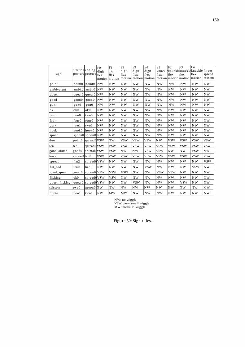
150
ambivalent ambi.0 ambi.0 NW NW NW NW NW NW NW NW NW NW
queer queer0 queer0 NW NW NW NW NW NW NW NW NW NW
good good0 good0 NW NW NW NW NW NW NW NW NW NW
gun gun0 gun0 NW NW NW NW NW NW NW NW NW NW
point point0 point0 NW NW NW NW NW NW NW NW NW NW
ok ok0 ok0 NW NW NW NW NW NW NW NW NW NW
two two0 two0 NW NW NW NW NW NW NW NW NW NW
four four0 four0 NW NW NW NW NW NW NW NW NW NWdark two1 two1 NW NW NW NW NW NW NW NW NW NW
hook hook0 hook0 NW NW NW NW NW NW NW NW NW NWspoon spoon0 spoon0 NW NW NW NW NW NW NW NW NW NW
dew point0 spread0VSW NW VSW VSW VSW NW VSW VSW VSW VSW
ten ten0 spread0VSW VSW VSW VSW VSW VSW VSW VSW VSW VSWgood_animal good0 animal0VSW VSW NW NW VSW VSW NW NW VSW NW
have spread0ten0 VSW VSW VSW VSW VSW VSW VSW VSW VSW VSW
spread flat2 spread0VSW NW NW NW NW NW NW NW NW VSW
fist_bad ten0 bad0 NW NW NW NW VSW NW NW NW VSW NW
good_spoon good0 spoon0 VSW VSW VSW NW NW VSW VSW NW NW NW
flicking ok0 spread0VSW VSW NW NW NW NW NW NW NW NWqueer_flicking queer0 spread0VSW NW NW VSW NW NW NW VSW NW NW
scissors two0 spoon0 NW NW NW NW NW NW NW NW NW MW
quote two1 two1 NW MW MW NW NW NW NW NW NW NW
signstartingposture
endingposture
F0digitflexmotion
F1digitflexmotion
F2digitflexmotion
F3digitflexmotion
F4digitflexmotion
F1knuckleflexmotion
F2knuckleflexmotion
F3knuckleflexmotion
F4knuckleflexmotion
fingerspreadmotion
NW: no wiggleVSW: very small wiggleMW: medium wiggle
Figure 50: Sign rules.

151
Appendix C
This appendix illustrates the recognition results of the signs, which were not
shown in the Chapter 5.
posture recognitionb/t a/t
FRAME 0
sign_ambivalent
sign recognition resultb/t a/t
posture recognitionb/t a/t
FRAME 3posture recognition
b/t a/t
FRAME 6
posture recognitionb/t a/t
FRAME 9posture recognition
b/t a/t
FRAME 12posture recognition
b/t a/t
FRAME 15
posture recognitionb/t a/t
FRAME 18posture recognition
b/t a/t
FRAME 21posture recognition
b/t a/t
FRAME 24
flat0(0.86)flat1(0.14)
flat0(0.86)flat1(0.14)
flat0(0.84)flat1(0.16)
flat0(0.84)flat1(0.16)
flat0(0.83)flat1(0.17)
flat0(0.82)flat1(0.17)
flat0(0.83)flat1(0.17)
flat0(0.83)flat1(0.17)
ambiva-lent0(0.25)
ambiva-lent0(0.25)
ambiva-lent0(0.44)
ambiva-lent0(0.44)
ambiva-lent0(0.45)
ambiva-lent0(0.45)
ambiva-lent0(0.45)
ambiva-lent0(0.45)
ambiva-lent0(0.45)
ambiva-lent0(0.45)
sign_ambivalent (0.45) sign_ambivalent (0.45)
Figure 51: Recognition result of sign_ambivalent.

152
posture recognitionb/t a/t
FRAME 0
sign recognition resultb/t a/t
posture recognitionb/t a/t
FRAME 3posture recognition
b/t a/t
FRAME 6
posture recognitionb/t a/t
FRAME 9posture recognition
b/t a/t
FRAME 12posture recognition
b/t a/t
FRAME 15
sign_queer
flat0(0.94)
flat0(0.94)
flat0(0.93)
flat0(0.93)
NF NF
queer0(0.22)
queer0(0.2)
queer0(0.46)flat1(0.2)four0(0.2)
queer0(0.46)
queer0(0.39)
queer0(0.39)
sign_queer (0.51) sign_queer (0.51)
Figure 52: Recognition result of sign_queer.

153
posture recognitionb/t a/t
FRAME 0
sign recognition resultb/t a/t
posture recognitionb/t a/t
FRAME 3posture recognition
b/t a/t
FRAME 6
posture recognitionb/t a/t
FRAME 9posture recognition
b/t a/t
FRAME 12posture recognition
b/t a/t
FRAME 15
posture recognitionb/t a/t
FRAME 18
sign_good
flat0(0.97)
flat0(0.97)
flat0(0.34)spread0(0.34)
flat0(0.2)spread0(0.2)
NF NF
good0(0.34)good1(0.1)
good0(0.34)good1(0.1)
good0(0.72)good1(0.1)
good0(0.72)good1(0.1)
good0(0.8)good1(0.1)
good0(0.79)good1(0.1)
good0(0.82)good1().1)
good0(0.82)good1(0.1)
sign_good (0.83) sign_good (0.83)
Figure 53: Recognition result of sign_good.

154
posture recognitionb/t a/t
FRAME 0
sign recognition resultb/t a/t
posture recognitionb/t a/t
FRAME 3posture recognition
b/t a/t
FRAME 6
posture recognitionb/t a/t
FRAME 9posture recognition
b/t a/t
FRAME 12posture recognition
b/t a/t
FRAME 15
sign_gun
flat0(0.97)
flat0(0.97)
flat0(0.96)
flat0(0.96)
NF NF
gun0(0.54)
gun0(0.53)
gun0(0.69)
gun0(0.69)
gun0(0.71)
gun0(0.71)
sign_gun (0.71) sign_gun (0.71)
Figure 54: Recognition result of sign_gun.

155
posture recognitionb/t a/t
FRAME 0
sign recognition resultb/t a/t
posture recognitionb/t a/t
FRAME 3posture recognition
b/t a/t
FRAME 6
posture recognitionb/t a/t
FRAME 9posture recognition
b/t a/t
FRAME 12posture recognition
b/t a/t
FRAME 15
sign_ok
flat0(0.97)
flat0(0.97)
spread0(0.6)flat0(0.4)flat1(0.36)etc.
spread0(0.59)ok0(0.36)flat1(0.31)etc.
ok0(0.6)
ok0(0.6)
ok0(0.45)flat2(0.12)flat1(0.12)etc.
ok0(0.45)
ok0(0.44)flat2(0.13)flat1(0.13)etc.
ok0(0.43)
ok0(0.41)flat1(0.14)flat1(0.14)etc.
ok0(0.4)
sign_ok (0.71) sign_ok (0.71)
Figure 55: Recognition result of sign_ok.

156
posture recognitionb/t a/t
FRAME 0
sign recognition resultb/t a/t
posture recognitionb/t a/t
FRAME 3posture recognition
b/t a/t
FRAME 6
posture recognitionb/t a/t
FRAME 9posture recognition
b/t a/t
FRAME 12posture recognition
b/t a/t
FRAME 15
sign_two
flat0(0.95)
flat0(0.95)
flat0(0.94)
flat0(0.94)
eight0(0.38)
eight0(0.38)
two0(0.6)
two0(0.6)
two0(0.73)
two0(0.73)
two0(0.82)queer0(0.17)
two0(0.82)
sign_two (0.82) sign_two (0.82)
Figure 56: Recognition result of sign_two.

157
posture recognitionb/t a/t
FRAME 0
sign recognition resultb/t a/t
posture recognitionb/t a/t
FRAME 3posture recognition
b/t a/t
FRAME 6
posture recognitionb/t a/t
FRAME 9posture recognition
b/t a/t
FRAME 12posture recognition
b/t a/t
FRAME 15
posture recognitionb/t a/t
FRAME 18posture recognition
b/t a/t
FRAME 21
sign_four
flat0(0.86)flat1(0.14)
flat0(0.86)flat1(0.14)
flat0(0.84)flat1(0.16)
flat0(0.84)flat1(0.16)
flat0(0.83)flat1(0.17)
flat0(0.83)flat1(0.17)
flat1(0.96)
flat1(0.96)
flat0(0.69)four0(0.31)flat1(0.3)
flat0(0.63)four0(0.36)flat1(0.29)
four0(0.5)
four0(0.39)
four0(0.42)
four0(0.3)
four0(0.39)
four0(0.26)
sign_four (0.81) sign_four (0.8)
Figure 57: Recognition result of sign_four.

158
posture recognitionb/t a/t
FRAME 0
sign recognition resultb/t a/t
posture recognitionb/t a/t
FRAME 3posture recognition
b/t a/t
FRAME 6
posture recognitionb/t a/t
FRAME 9posture recognition
b/t a/t
FRAME 12posture recognition
b/t a/t
FRAME 15
sign_dark
flat0(0.98)
flat0(0.98)
flat0(0.96)
flat0(0.96)
NF NF
two1(0.45)two0(0.31)
two1(0.45)two0(0.3)
two1(0.67)
two1(0.67)
two1(0.7)two0(0.1)
two1(0.69)
sign_dark (0.71) sign_dark (0.71)
Figure 58: Recognition result of sign_dark.

159
posture recognitionb/t a/t
FRAME 0
sign recognition resultb/t a/t
posture recognitionb/t a/t
FRAME 3posture recognition
b/t a/t
FRAME 6
posture recognitionb/t a/t
FRAME 9posture recognition
b/t a/t
FRAME 12posture recognition
b/t a/t
FRAME 15
posture recognitionb/t a/t
FRAME 18posture recognition
b/t a/t
FRAME 21posture recognition
b/t a/t
FRAME 24
sign_hook
flat0(0.97)
flat0(0.97)
flat0(0.9)
flat0(0.9)
flat0(0.69)flat1(0.11)
flat0(0.62)flat1(0.11)
flat0(0.29)flat1(0.11)
flat0(0.15)flat1(0.11)
gun0(0.35)
gun0(0.35)
point0(0.51)hook0(0.49)two1(0.28)
point0(0.49)hook0(0.47)two1(0.27)
hook0(0.56)point0(0.44)two1(0.22)
hook0(0.56)point0(0.4)two1(0.21)
hook0(0.58)point0(0.42)
hook0(0.58)point0(0.38)
hook0(0.58)point0(0.42)
hook0(0.58)point0(0.37)
sign_hook (0.58) sign_hook (0.58)
Figure 59: Recognition result of sign_hook.

160
posture recognitionb/t a/t
FRAME 0
sign recognition resultb/t a/t
posture recognitionb/t a/t
FRAME 3posture recognition
b/t a/t
FRAME 6
posture recognitionb/t a/t
FRAME 9posture recognition
b/t a/t
FRAME 12posture recognition
b/t a/t
FRAME 15
posture recognitionb/t a/t
FRAME 18
sign_spoon
flat0(0.96)
flat0(0.96)
flat0(0.95)
flat0(0.95)
flat0(0.85)flat1(0.15)
flat0(0.85)flat1(0.15)
NF NF spoon0(0.34)
spoon0(0.34)
spoon0(0.8)
spoon0(0.8)
spoon0(0.66)
spoon0(0.64)
sign_spoon (0.8) sign_spoon (0.8)
Figure 60: Recognition result of sign_spoon.
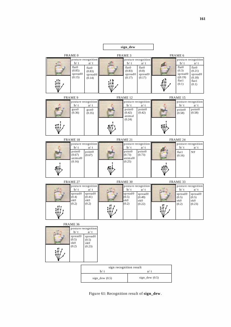
161
posture recognitionb/t a/t
FRAME 0
sign_dew
sign recognition resultb/t a/t
posture recognitionb/t a/t
FRAME 3posture recognition
b/t a/t
FRAME 6
posture recognitionb/t a/t
FRAME 9posture recognition
b/t a/t
FRAME 12posture recognition
b/t a/t
FRAME 15
posture recognitionb/t a/t
FRAME 18posture recognition
b/t a/t
FRAME 21posture recognition
b/t a/t
FRAME 24
posture recognitionb/t a/t
FRAME 27posture recognition
b/t a/t
FRAME 30posture recognition
b/t a/t
FRAME 33
posture recognitionb/t a/t
FRAME 36
flat0 (0.85)spread0(0.15)
flat0(0.83)spread0(0.17)
flat0(0.3)spread0((0.19)flat1(0.1)
gun0(0.36)
point0(0.42)animal(0.24)
point0(0.58)
point0(0.67)animal0(0.16)
point0(0.73)animal0(0.25)
flat1(0.16)
spread0(0.4)ok0(0.2)
spread0(0.5)ok0(0.2)
spread0(0.5)ok0(0.2)
spread0(0.5)ok0(0.2)
sign_dew (0.5)
flat0(0.83)spread0(0.14)
flat0(0.8)spread0(0.17)
flat0(0.21)spread0(0.18)flat1(0.1)
gun0(0.35)
point0(0.42)
point0(0.58)
point0(0.67)
point0(0.73)
NF
spread0(0.41)ok0(0.2)
spread0(0.49)ok0(0.22)
spread0(0.5)ok0(0.23)
spread0(0.5)ok0(0.23)
sign_dew (0.5)
Figure 61: Recognition result of sign_dew.

162
posture recognitionb/t a/t
FRAME 0
sign recognition resultb/t a/t
posture recognitionb/t a/t
FRAME 3posture recognition
b/t a/t
FRAME 6
posture recognitionb/t a/t
FRAME 9posture recognition
b/t a/t
FRAME 12posture recognition
b/t a/t
FRAME 15
posture recognitionb/t a/t
FRAME 18posture recognition
b/t a/t
FRAME 21posture recognition
b/t a/t
FRAME 24
posture recognitionb/t a/t
FRAME 27posture recognition
b/t a/t
FRAME 30posture recognition
b/t a/t
FRAME 33
posture recognitionb/t a/t
FRAME 36posture recognition
b/t a/t
FRAME 39posture recognition
b/t a/t
FRAME 42
sign_good_animal
flat0(0.96)
flat0(0.96)
flat0(0.95)
flat0(0.95)
spread0(0.58)flat0(0.42)
spread0(0.54)flat0(0.33)
NF NF good0(0.12)
good0(0.12)
good0(0.42)
good0(0.42)
good0(0.57)
good0(0.57)
good0(0.64)
good0(0.64)
ambiva-lent(0.24)
ambiva-lent(0.24)
NF NF NF NF animal0(0.2)
animal0(0.2)
animal0(0.58)
animal0(0.57)
animal0(0.6)
animal0(0.6)
animal0(0.61)
animal0(0.6)
NF sign_good_animal (0.6)
Figure 62: Recognition result of sign_good_animal.

163
posture recognitionb/t a/t
FRAME 0
sign recognition resultb/t a/t
posture recognitionb/t a/t
FRAME 3posture recognition
b/t a/t
FRAME 6
posture recognitionb/t a/t
FRAME 9posture recognition
b/t a/t
FRAME 12posture recognition
b/t a/t
FRAME 15
posture recognitionb/t a/t
FRAME 18posture recognition
b/t a/t
FRAME 21posture recognition
b/t a/t
FRAME 24
posture recognitionb/t a/t
FRAME 27
sign_have
flat0(0.98)
flat0(0.98)
spread0(0.55)flat0(0.45)flat1(0.17)
spread0(0.55)flat0(0.36)flat1(0.17)
spread0(0.7)ok0(0.2)
spread0(0.67)ok0(0.2)
spread0(0.77)ok0(0.2)
spread0(0.72)ok0(0.2)
spread0(0.64)ok0(0.2)
spread0(0.56)ok0(0.2)
NF NF
good1(0.55)good0(0.34)
good1(0.53)good0(0.34)
good1(0.5)ten0(0.5)
good1(0.5)ten0(0.5)
ten0(0.61)good1(0.39)
ten0(0.61)good1(0.39)
ten0(0.62)good1(0.38)
ten0(0.62)good1(0.38)
sign_have (0.63) sign_have (0.63)
Figure 63: Recognition result of sign_have.

164
posture recognitionb/t a/t
FRAME 0
sign recognition resultb/t a/t
posture recognitionb/t a/t
FRAME 3posture recognition
b/t a/t
FRAME 6
posture recognitionb/t a/t
FRAME 9posture recognition
b/t a/t
FRAME 12posture recognition
b/t a/t
FRAME 15
posture recognitionb/t a/t
FRAME 18posture recognition
b/t a/t
FRAME 21posture recognition
b/t a/t
FRAME 24
posture recognitionb/t a/t
FRAME 27posture recognition
b/t a/t
FRAME 30posture recognition
b/t a/t
FRAME 33
sign_spread
flat0(0.85)flat1(0.15)
flat0(0.85)flat1(0.15)
flat0(0.57)flat1(0.43)
flat0(0.57)flat1(0.43)
flat1(0.81)flat2(0.19)
flat1(0.81)flat2(0.19)
flat2(0.96)
flat2(0.96)
flat2(0.92)
flat2(0.91)
flat2(0.86)four0(0.14)
flat2(0.84)four0(0.14)
flat2(0.84)flat1(0.16)four0(0.15)
flat2(0.83)flat1(0.16)four0(0.15)
flat1(0.39)ok0(0.3)
flat1(0.3)ok0(0.3)
spread0(0.35)ok0(0.25)
spread0(0.35)ok0(0.25)
spread0(0.43)ok0(0.21)
spread0(0.43)ok0(0.21)
spread0(0.53)ok0(0.13)
spread0(0.53)ok0(0.13)
spread0(0.57)ok0(0.12)
spread0(0.57)ok0(0.12)
sign_spread (0.58) sign_spread (0.53)
Figure 64: Recognition result of sign_spread.
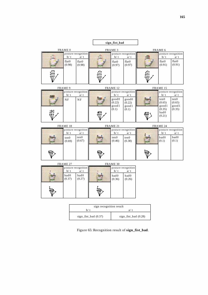
165
posture recognitionb/t a/t
FRAME 0
sign recognition resultb/t a/t
posture recognitionb/t a/t
FRAME 3posture recognition
b/t a/t
FRAME 6
posture recognitionb/t a/t
FRAME 9posture recognition
b/t a/t
FRAME 12posture recognition
b/t a/t
FRAME 15
posture recognitionb/t a/t
FRAME 18posture recognition
b/t a/t
FRAME 21posture recognition
b/t a/t
FRAME 24
posture recognitionb/t a/t
FRAME 27posture recognition
b/t a/t
FRAME 30
flat0(0.98)
flat0(0.98)
flat0(0.97)
flat0(0.97)
flat0(0.91)
flat0(0.91)
NF NF good0(0.22)good1(0.1)
good0(0.22)good1(0.1)
ten0(0.65)good1(0.35)bad0(0.21)
ten0(0.65)good1(0.35)
ten0(0.69)
ten0(0.67)
ten0(0.46)
ten0(0.38)
bad0(0.1)
bad0(0.1)
bad0(0.37)
bad0(0.27)
bad0(0.36)
bad0(0.26)
sign_fist_bad (0.37) sign_fist_bad (0.28)
sign_fist_bad
Figure 65: Recognition result of sign_fist_bad.

166
posture recognitionb/t a/t
FRAME 0
sign recognition resultb/t a/t
posture recognitionb/t a/t
FRAME 3posture recognition
b/t a/t
FRAME 6
posture recognitionb/t a/t
FRAME 9posture recognition
b/t a/t
FRAME 12posture recognition
b/t a/t
FRAME 15
posture recognitionb/t a/t
FRAME 18posture recognition
b/t a/t
FRAME 21posture recognition
b/t a/t
FRAME 24
posture recognitionb/t a/t
FRAME 27
sign_flicking
spread0(0.77)flat0(0.23)
spread0(0.77)flat0(0.11)
spread0(0.61)flat0(0.39)
spread0(0.61)flat0(0.3)
spread0(0.59)
spread0(0.56)
ok0(0.27)spread0(0.24)
ok0(0.26)spread0(0.24)
ok0(0.14)
ok0(0.12)
NF NF
spread0(0.14)
spread0(0.14)
spread0(0.28)
spread0(0.28)
spread0(0.32)
spread0(0.32)
spread0(0.32)
spread0(0.32)
sign_flicking (0.27) sign_flicking (0.26)
Figure 66: Recognition result of sign_flicking. In this sequence, the tracker falsely
recognise the first posture as posture_spread0 which should be posture_flat0. This
however, didn't affect the finial result, because posture_spread0 is an intermediate
posture between posture_flat0 (assumed initial posture) and posture_ok0 (the start
posture of the sign), thus the posture_ok0 is recognised correctly as the starting posture.
This motion analysis process was described in section 4.5.2.1.

167
posture recognitionb/t a/t
FRAME 0
sign recognition resultb/t a/t
posture recognitionb/t a/t
FRAME 3posture recognition
b/t a/t
FRAME 6
posture recognitionb/t a/t
FRAME 9posture recognition
b/t a/t
FRAME 12posture recognition
b/t a/t
FRAME 15
posture recognitionb/t a/t
FRAME 18posture recognition
b/t a/t
FRAME 21posture recognition
b/t a/t
FRAME 24
posture recognitionb/t a/t
FRAME 27posture recognition
b/t a/t
FRAME 30posture recognition
b/t a/t
FRAME 33
posture recognitionb/t a/t
FRAME 36posture recognition
b/t a/t
FRAME 39
sign_queer_flicking
flat0(0.96)
flat0(0.96)
flat0(0.93)
flat0(0.93)
spread0(0.59)flat0(0.41)flat1(0.24)
spread0(0.59)flat0(0.32)flat1(0.24)
flat0(0.21)flat2(0.21)four0(0.21)
NF queer0(0.28)
queer0(0.26)
queer0(0.57)spoon0(0.31)two0(0.31)etc.
queer0(0.48)spoon0(0.31)two0(0..27)
queer0(0.56)two0(0.34)four0(0..25)
queer0(0.48)two0(0.33)spoon0(0..25)
queer0(0.56)two0(0.35)four0(0..23)
queer0(0.56)two0(0.35)four0(0.13)
queer0(0.56)two0(0.35)four0(0.21)etc.
queer0(0.47)two0(0.35)four0(0.12)
two0(0.28)queer0(0.28)ok0(0.18)etc.
two0(0.28)queer0(0.28)
ok0(0.29)
ok0(0.29)
spread0(0.39)ok0(0.29)
spread0(0.39)ok0(0.29)
spread0(0.45)ok0(0.29)
spread0(0.49)ok0(0.29)
spread0(0.46)ok0(0.29)
spread0(0.46)ok0(0.29)
sign_queer_flicking (0.46) sign_queer_flicking (0.46)
Figure 68: Recognition result of sign_queer_flicking.

168
posture recognitionb/t a/t
FRAME 0
sign_quote
sign recognition resultb/t a/t
posture recognitionb/t a/t
FRAME 3posture recognition
b/t a/t
FRAME 6
posture recognitionb/t a/t
FRAME 9posture recognition
b/t a/t
FRAME 12posture recognition
b/t a/t
FRAME 15
posture recognitionb/t a/t
FRAME 18posture recognition
b/t a/t
FRAME 21posture recognition
b/t a/t
FRAME 24
posture recognitionb/t a/t
FRAME 27posture recognition
b/t a/t
FRAME 30posture recognition
b/t a/t
FRAME 33
posture recognitionb/t a/t
FRAME 36posture recognition
b/t a/t
FRAME 39
spread0(0.7)flat1(0.25)flat0(0.25)
spread0(0.72)flat1(0.13)flat0(0.13)
four0(0.22)flat2(0.13)flat1(0.13)
NF two0(0.38)two1(0.24)ok0(0.11)etc.
two0(0.38)two1(0.24)
two0(0.44)two1(0.3)
two0(0.44)two1(0.3)
two0(0.47)two1(0.43)
two1(0.43)two0(0.42)
two1(0.41)two0(0.29)
two1(0.42)two0(0.23)
two1(0.41)two0(0.26)
two1(0.41)two0(0.2)
two0(0.5)two1(0.22)queer0(0.21)
two1(0.5)two0(0.11)queer0(0.11)
two0(0.48)two1(0.19)
two0(0.5)two1(0.19)
two0(0.48)two1(0.18)
two0(0.47)two1(0.18)
two0(0.5)two1(0.18)
two0(0.49)two1(0.18)
two0(0.39)two1(0.33)
two0(0.34)two1(0.33)
two1(0.35)two0(0.35)
two1(0.35)two0(0.3)
two1(0.35)two0(0.32)
two1(0.35)two0(0.27)
sign_quote (0.41) sign_quote (0.41)
Figure 68: Recognition result of sign_quote.

169
Bibliography
Bichsel, M. (1995). Human face recognition: From views to models - from
models to views, International Workshop on Automatic Face and Gesture
Recognition, Zurich, pp. 59-64.
Charayphan, C. and Marble, A. E. (1992). Image processing system for
interpreting motion in ASL, Journal of Biomedical Engineering 14(5): 419-
435.
Cox, E. (1992). Fuzzy fundamentals, IEEE Spectrum (October): 58-61.
Cox, E. (1993). Adaptive fuzzy systems, IEEE Spectrum (February): 27-31.
Craig, J. (1986). Introduction to Robotics Mechanics and Control, Addison-Wesley
Publishing Company Inc.
Darrell, T. and Pentland, A. (1993). Space-time gestures, Proceedings of IEEE
Conference on Computer Vision and Pattern Recognition, pp. 335-340.
Darrell, T. and Pentland, A. (1995). Attention-driven expression and gesture
analysis in an interactive environment, International Workshop on
Automatic Face and Gesture Recognition, Zurich, pp. 135-140.
Davis J., and Shah, M. (1994). Visual gesture recognition, IEE Proceedings -
Vision, Image, and Signal Processing, Stockolm, May, pp. 101-106.

170
Dorner, B. (1993). Hand shape identification and tracking for sign language
interpretation, In 'Looking at People: Recognition and Interpretation of Human
Action', Workshop WS26 at the International Joint Conference on Artificial
Intelligence (IJCAI-93), Chambery, France.
Dorner, B. (1994A). Chasing the colour glove: Visual hand tracking, Master's
dissertation, Department of Computer Science, Simon Fraser University.
Dorner, B. and Hagen, E. (1994B). Towards an American Sign Language
interface. (Private communication)
Du Plessis, R. M. (1969). Poor man's explanation of Kalman filtering or How I
stopped worrying and learned to love matrix inversion, North American
Aviation, Inc., Automatics Division.
Eglowstein, H. (1990). Reach Out and Touch Your Data, Byte (July): 283-290.
Essa, I. A. and Pentland, A. (1995). Facial expression recognition using visually
extracted facial action parameters, International Workshop on Automatic
Face and Gesture Recognition, Zurich, pp. 35-40.
Fels, S. S. and Hinton, G. E. (1993). Glove-Talk: A neural network interface
between a data-glove and a speech synthesizer, IEEE Transactions on
Neural Networks 4(1): 2-8.

171
Foley, J. D. and Van Dam, A. (1984). Fundamentals of Interactive Computer
Graphics, Addison-Wesley Publishing Company, pp. 593-622.
Freeman, W. T. and Roth, M. (1995). Orientation histograms for hand gesture
recogntition, International Workshop on Automatic Face and Gesture
Recognition, Zurich, pp. 296-300.
Gennery, G. (1992). Visual tracking of known three-dimensional objects,
International Journal of Computer Vision 7(3): 243-270.
Graf, H. P., Chen, T., Petajan, E. and Cosatto, E. (1995). Locating faces and
facial parts, International Workshop on Automatic Face and Gesture
Recognition, Zurich, pp. 41-46.
Holden, E. J. (1991). Graphical representation of hand movement as in deaf sign
language: The Hand Sign Translator system, MSc thesis, University of
Western Australia.
Holden, E. J. and Roy, G. G. (1992A). Learning tool for Signed English using
graphical hand animation, Proceedings of the 1992 ACM/SIGAPP
Symposium on Applied Computing, Vol. 1, pp. 444-449.
Holden, E. J. and Roy, G. G. (1992B). The graphical translation of English text
into signed English in the Hand Sign Translator system, Computer
Graphics Forum (Eurographics ‘92) 11(3): C357-C366.

172
Holden, E. J. (1993). Current status of the SMU system, Tech Report 93/7,
Department of Computer Science, University of Western Australia,
November.
Holden, E. J., Roy, G. G. and Owens, R. (1994). Recognition of sign motion,
Proceedings of the 1994 Western Australian Computer Science Symposium.
Holden, E. J., Roy, G. G. and Owens, R. (1995). Adaptive classification of hand
movement, Proceedings of IEEE International Conference on Neural Networks,
Vol. 3, pp. 1373-1378.
Holden, E. J., Roy, G. G. and Owens, R. (1997). Hand movement classification
using an adaptive fuzzy expert system, International Journal of Expert
Systems (in press).
Hunter, E., Schlenzig J. and Jain, R. (1995), Posture estimation in reduced-
model gesture input systems, International Workshop on Automatic Face and
Gesture Recognition, Zurich, pp. 290-295.
Huntsberger, T. L., Jacobs, C. L. and Cannon, R. L. (1985). Interactive fuzzy
image segmentation, Pattern Recognition 18(2): 131-128.
Jeanes, R., Reynolds, B. and Coleman, B. (1981). A Report on the Work of the
Australian Sign Language Development Project, The Australian Teacher of
the Deaf 22: 68-69.

173
Jeanes, R., Reynolds, B. and Coleman, B. (1989). Dictionary of Australasian Signs
for Communication with the Deaf, Victorian School for Deaf Children,
Australia.
Johansson, G. (1973). Visual perception of biological motion and a model for
its analysis, Perception & Psychophysics 14(2): 201-211.
Johnston, T. A. (1989). Auslan Dictionary: A dictionary of the sign language of the
Australian deaf community, Deafness Resources, Australia.
Kosko, B. (1992). Neural Networks and Fuzzy Systems: A Dynamic Systems
Approach To Machine Intelligence, Prentice-Hall International Editions.
Kozlowski, L. T. and Cutting, J. E. (1977). Recognizing the sex of a walker
from a dynamic point-light display, Perception & Psychophysics 21(6): 575-
580.
Kumar R. R. R., Tirumalai, A. and Jain, R. C. (1989). A non-linear optimization
algorithm for the estimation of structure and motion parameters,
Proceedings of Computer Society Conference on Computer Vision and Pattern
Recognition, June, SanDiego, California, pp. 136-143.
Long, W. and Yang, Y. H. (1991). Log-tracker: An attribute-based approach to
tracking human body motion, International Journal of Pattern Recognition
and Artificial Intelligence 5(3): 439-458.
174
Lowe, D. G. (1980). Solving for the parameters of object models from image
descriptions, Proceedings of ARPA Image Understanding Workshop, College
Park, MC, April, pp. 121-127.
Lowe, D. G. (1991). Fitting parameterized three-dimensional models to
images. IEEE Transactions on Pattern Analysis and Machine Intelligence
13(5): 441-450.
MacDougall, J. (1988). The development of the Australasian Signed English
system, The Australian Teacher of the Deaf 28: 18-36.
Martin, W. N. and Aggarwal, J. K. (1978). Survey dynamic scene analysis,
Computer Graphics and Image Processing 7: 356-374.
McKeown, J. J., Meegan, D. and Sprevak, D. (1990). An introduction to
unconstrained optimisation, IOP Publishing Ltd.
McKerrow, P. J. (1991). Introduction to Robotics, Addison-Wesley Publishing
Company.
Martin, W. and Aggarwal, J. K. (1979). Computer analysis of dynamic scenes
containing curvilinear figures, Pattern Recognition 11: 169-178.
Moses, Y., Reynard, D. and Blake, A. (1995). Determining facial expressions in
real time, International Workshop on Automatic Face and Gesture Recognition,
Zurich, pp. 332-337.
175
Murakami, K. and Taguchi, H. (1991). Gesture Recognition using Recurrent
Neural Networks, CHI'91 Conference proceedings, Human Factors in
Computing Systems, Reading through Technology, pp. 237-242.
Negoita, C. V. (1985). Expert Systems and Fuzzy Systems, The Benjamin
/Cummings Publishing Company, Inc.
Pal, S. K. and Rosenfeld, A. (1988). Image enhancement and thresholding by
optimization of fuzzy compactness, Pattern Recognition Letters 7: 77-86.
Poizner, H., Bellugi, U. and Lutes-Driscoll, V. (1981). Perception of American
sign language in dynamic point-light displays, Journal of Experimental
Psychology: Human Perception and Performance 7(2): 430-440.
Popovic, D. and Liang, N. (1994). Fuzzy approach in model-based object
recognition, Proceedings of IEEE 3rd International Conference on Fuzzy
Systems, pp. 1801-1808.
Press, W. H., Teukolsky, S. A., Vetterling, W. T. and Flannery, B. P. (1992).
Numerical Recipes in C, The Art of Scientific Computing, Second edition,
Cambridge University Press.
Regh, J. and Kanade, T. (1993). DigitEyes: Vision-based human hand tracking.
Technical Report CMU-CS-93-220, School of Computer Science, Carnegie
Mellon University.
Rijpkema, H. and Girard, M. (1991). Computer animation of knowledge-based
human grasping, Computer Graphics 25(4): 339-348.

176
Roach, J. W. and Aggarwal, J. K. (1980). Determining the movement of objects
from a sequence of images, IEEE Transactions on Pattern Analysis and
Machine Intelligence PAMI-2(6): 554-562.
Roberts, L. G. (1965). Machine perception of three-dimensional solids, Optical
Electro-optical Information Processing, J. Tippet et al. Eds., Cambridge,
MA:MIT Press, pp. 159-197.
Smith, A. R. (1978). Color gamut transform pairs, SIGGRAPH'78 Proceedings,
published as Computer Graphics, 13 (2): 276-283.
Sorenson, H. W. (1970). Least-squares estimation: from Gauss to Kalman, IEEE
Spectrum, July, pp. 63-68.
Starner, T. and Pentland, A. (1995). Visual recognition of American sign
language using hidden markov models, International Workshop on
Automatic Face and Gesture Recognition, Zurich, pp. 189-194.
Steinhardt, A. O. (1988). Householder transforms in signal processing, IEEE
ASSP Magazine, July, pp. 4-12.
Stokoe, W. C., Casterline, D. C. and Croneberg, C. G. (1976). A Dictionary of
American Sign Language on Linguistic Principles, Linstok Press, new
edition.

177
Sumi, Y. and Ohta, Y. (1995). Detection of face orientation and facial
components using distributed appearance modelling, International
Workshop on Automatic Face and Gesture Recognition, Zurich, pp. 254-259.
Takacs, B. and Wechsler, H. (1995). Face location using a dynamic model of
retinal feature extraction, International Workshop on Automatic Face and
Gesture Recognition, Zurich, pp. 243-247.
Tamura, S. and Kawasaki, S. (1988). Recognition of sign language motion
images, Pattern Recognition 21(4): 343-353.
Tsotsos, J. K., Mylopoulos, J., Covvey, H. D. and Zucker, S. W. (1980) A
Framework for Visual Motion Understanding, IEEE Transactions on
Pattern Analysis and Machine Intelligence PAMI-2(6): 563-573.
Uras, C. and Verri, A. (1995). Hand Gesture Recognition from Edge Maps.
International Workshop on Automatic Face and Gesture Recognition, Zurich,
pp. 116-121.
Ushida, H., Imura, A., Yamaguchi, T. and Takagi, T. (1994). Human_motion
recognition by means of fuzzy associative Inference, Proceedings of 1994
IEEE 3rd International Conference on Fuzzy Systems, pp. 813-818.
Vaanaanen, K. and Bohm, K. (1994). Gesture driven interaction as a human
factor in virtual environments - an approach with neural networks, In, R.
A., Gigante M. A., and Jones, H. (Eds.), Virtual Reality Systems, Earnshaw,
Academic Press, pp. 93-106.

178
Vanger, P., Honlinger, R. and Haken, H. (1995). Applications of synergetics in
decoding facial expressions of emotion, International Workshop on
Automatic Face-and Gesture Recognition, Zurich, pp. 24-29.
Vamplew, P. and Adams, A. (1995). Recognition and anticipation of hand
motions using a recurrent neural network, Proceedings of IEEE
International Confference on Neural Networks, Vol 3, pp. 2904-2907.
Wilson, E. and Anspach, G. (1993). Neural networks for sign language
translation, SPIE: Applications of Artificial Neural networks 4: 589-599.
Yoshikawa, T. (1990). Foundation of Robotics Analysis and Control, The MIT
Press, Cambridge, Messachusetts.
Zadeh, L. A. (1965). Fuzzy sets, Information Control 8: 338-353.


![arXiv:1912.01944v1 [cs.CV] 4 Dec 2019arXiv:1912.01944v1 [cs.CV] 4 Dec 2019. are manual gestures, while non-manual gestures like head movements (e.g. nodding), body ... HMM for recognition](https://img.pdfslide.net/doc/110x75/5e9305c318f29026f8525895/arxiv191201944v1-cscv-4-dec-2019-arxiv191201944v1-cscv-4-dec-2019-are.jpg)