Embed Size (px)
Citation preview

1
Proceedings of IDETC/CIE 2006 ASME 2006 International Design Engineering Technical Conferences &
Computers and Information in Engineering Conference September 10-13, 2006, Philadelphia, Pennsylvania, USA
DETC2006-99572
VISUAL REPRESENTATIONS AS AN AID TO CONCEPT GENERATION
Abstract. This paper describes our initial efforts to develop a 3D visualization tool that is part of an overall effort to create a Concept Generator, an automated conceptual design tool, to aid a designer during the early stages of the design process. The use of CAD software has diversified into various disciplines that have made use of simulation and software modeling tools for reasons that range from improving accuracy in design, reduction in lead times, and simple visualizations. The impacts of CAD software have been beneficial in industry and education. Described in this paper is the use of low-memory VRML models to represent components. These low memory models have been created to achieve several goals that complement the overall objectives of the concept generator. One key goal is that the concept generator be accessible via the web, thus the need for low-memory and low-data models. Additionally, as the concept generator is intended for usage during early conceptual design, the 3D visualization tool allows the creation of models upon which basic manipulations can be performed so that a designer can get an initial feel of the structure that his product is going to take. Our research has enabled us to create a basic visualization tool which, while similar in nature to most other CAD software tools, is unique, in that it represents the link, as a visual interface, between a formulated concept and the designer. The paper presents the research problem, an overview of the architecture of the software tool and some preliminary results on visual representations as an aid to concept generation.
1. Introduction. This paper describes our initial efforts to develop a 3D visualization tool that is to complement the output of recent automated concept generation techniques [1-3]. The specific goal of the visualization tool is to enable a designer to quickly explore different product architectures after particular candidate form solutions have been identified to solve required product functions. The visualization tool is not intended for detailed geometric design of specific components. The concept generator is a computer based, automated concept generation tool that can access a design repository to suggest candidate solution concepts [1, 2, 4, 5]. The concept generator and associated design repository operate over the internet. This is a key aspect of the visualization tool in that it utilizes methods that require minimal data and memory so as to enable fast transmission over the internet. The development of the tool is based on existing design theories, which also guide the working principle of the Concept Generator. The scope of the research presented here is limited to the validation of the feasibility of such a software tool within a set of specified requirements, and not to assess the capability of the tool itself. While there are many CAD packages available today that allow for very sophisticated geometric modeling and types of analysis, they are not suitable for our intended use and integration with the concept generator. The goal is a visualization tool that operates on data-light models and requires minimal computational and bandwidth resources. Nevertheless, the tool must still be ergonomic and intuitive. In many ways, we are developing a CAD tool that is the equivalent of the designer’s initial sketchpad. In the way that the designer
Andrea De Crescenzo Department of Mechanical Engineering
Politecnico di Milano, Milano, Italy
Email: [email protected]
Attaluri Vivek, Daniel A. McAdams Department of Mechanical &
Aerospace Engineering University of Missouri-Rolla
Rolla, MO, 65409, USA Email: [email protected], [email protected]
Robert B. Stone Department of Interdisciplinary Engineering
University of Missouri-Rolla Rolla, MO, 65409, USA Email: [email protected]

2
initially sketches out cylinders for motors, disks for gears, lines for belts, and other simplifications of real geometry to explore potential layouts and product architectures, the visualization tool will represent components in terms of their gross geometry and allow the rapid configuration and re-configuration of components. With such a tool, the concept generator can suggest specific components to solve needed functions, provide an initial workspace with component geometries placed in it, and allow the designer to move these components around in the search for efficient arrangements. This paper presents the general research problem and the results to date on the tool development. Basic tool architecture and visualization capabilities are outlined. Section 2 describes background work by this research team, and the need for a visualization tool, and also the groundwork upon which the tool was to be based on. Section 3 describes similar related work by various other researchers. Section 4 introduces a formalization of the problem and describes the technical issues that are posed and how some of them were overcome. Also described in detail is the structure and data flow of the code. Initial results of the visualization tool study and conclusions on its impact complete the paper. 2. Background. 2.1 The Concept Generator. The activity of concept generation has long been the domain of experienced designers with substantial product knowledge, vision and inherent creativity. Until recently, the process of concept generation lacked formal methods and structure [6]. The lack of formal methods made it difficult to pass on accrued knowledge to a fresh generation of engineering designers. Also, experience alone, without a clear methodology, did not necessarily guarantee the exploration and evaluation of all possibilities that could lead to the most efficient solution. In the last two decades or so, many approaches have attempted to devise a clear-cut methodology that would be universally acceptable and applicable [6-13] . On a parallel path, automating the design process to a stage where human expertise is required only in select areas, while assigning the more monotonous tasks to software, is as
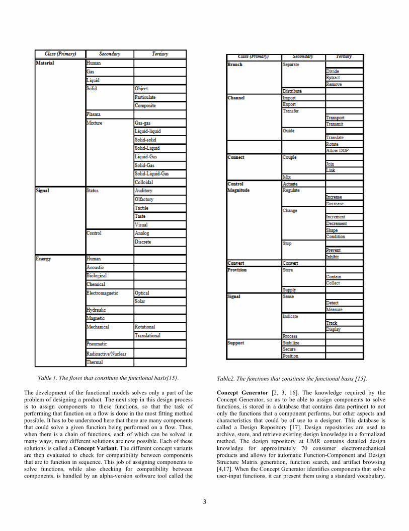
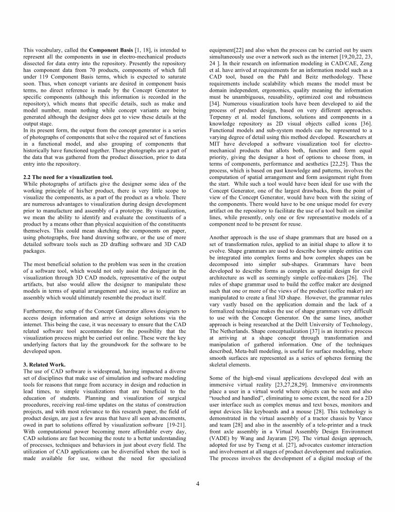
much of a requirement, in terms of minimizing resources spent, as it is a luxury. One such approach being researched at UMR to automate the process of concept generation is based on the utilization of descriptive methods, stored knowledge, algorithmic reasoning, and computational methods. The procedure begins with the creation of Functional Models, defined as “a description of a product or process in terms of the elementary functions that are required to achieve its overall function or purpose. Functional models represent a form independent blueprint of a product. Functional modeling is a key step in the product design process, whether original or redesign” [14] Thus with the inputs (required resources) and outputs (required performance) of the product being known, a detailed sequence of events can be described so as to eventually arrive at the desired result from the inputs. This description of events, constituting a Functional Model is done by building phrases using words from a pre-defined vocabulary called a Functional Basis [15]. This vocabulary was created to ensure that while the designer’s thoughts were expressed, conveyed and documented clearly, they were also were interpreted with no ambiguity by other designers. To build a functional model functions are expressed as verb-object pairs where verbs are chosen from basis functions and the objects are chosen from basis flows. Flows are the quantities that are input and output by functions and represent the entities upon which functions are performed. Flows have been classified into primary, secondary and tertiary levels, with the primary types consisting of matter, energy and information as defined by Pahl and Beitz [10]. The flow terms are shown in Table 1. In a similar manner, functions are also categorized into primary, secondary and tertiary levels and the terms are shown in Table 2. The example shown below (Fig. 1) demonstrates the use of the functional basis in the building of functional models. Also shown are the Flows and the Functions that constitute the Functional Basis.
Figure 1. Sub-functions of a functional model showing the conversion of Electrical Energy to Mechanical Energy. An example of a component that could perform the above functions would be a motor.
Import Electrical Energy
Convert Electrical Energy to Mechanical Energy
E.E E.E M.E
3
Table 1. The flows that constitute the functional basis[15].
Table2. The functions that constitute the functional basis [15].
The development of the functional models solves only a part of the problem of designing a product. The next step in this design process is to assign components to these functions, so that the task of performing that function on a flow is done in the most fitting method possible. It has to be understood here that there are many components that could solve a given function being performed on a flow. Thus, when there is a chain of functions, each of which can be solved in many ways, many different solutions are now possible. Each of these solutions is called a Concept Variant. The different concept variants are then evaluated to check for compatibility between components that are to function in sequence. This job of assigning components to solve functions, while also checking for compatibility between components, is handled by an alpha-version software tool called the
Concept Generator [2, 3, 16]. The knowledge required by the Concept Generator, so as to be able to assign components to solve functions, is stored in a database that contains data pertinent to not only the functions that a component performs, but other aspects and characteristics that could be of use to a designer. This database is called a Design Repository [17]. Design repositories are used to archive, store, and retrieve existing design knowledge in a formalized method. The design repository at UMR contains detailed design knowledge for approximately 70 consumer electromechanical products and allows for automatic Function-Component and Design Structure Matrix generation, function search, and artifact browsing [4,17]. When the Concept Generator identifies components that solve user-input functions, it can present them using a standard vocabulary.
4
This vocabulary, called the Component Basis [1, 18], is intended to represent all the components in use in electro-mechanical products dissected for data entry into the repository. Presently the repository has component data from 70 products, components of which fall under 119 Component Basis terms, which is expected to saturate soon. Thus, when concept variants are desired in component basis terms, no direct reference is made by the Concept Generator to specific components (although this information is recorded in the repository), which means that specific details, such as make and model number, mean nothing while concept variants are being generated although the designer does get to view these details at the output stage. In its present form, the output from the concept generator is a series of photographs of components that solve the required set of functions in a functional model, and also grouping of components that historically have functioned together. These photographs are a part of the data that was gathered from the product dissection, prior to data entry into the repository. 2.2 The need for a visualization tool. While photographs of artifacts give the designer some idea of the working principle of his/her product, there is very little scope to visualize the components, as a part of the product as a whole. There are numerous advantages to visualization during design development prior to manufacture and assembly of a prototype. By visualization, we mean the ability to identify and evaluate the constituents of a product by a means other than physical acquisition of the constituents themselves. This could mean sketching the components on paper, using photographs, free hand drawing software, or the use of more detailed software tools such as 2D drafting software and 3D CAD packages. The most beneficial solution to the problem was seen in the creation of a software tool, which would not only assist the designer in the visualization through 3D CAD models, representative of the output artifacts, but also would allow the designer to manipulate these models in terms of spatial arrangement and size, so as to realize an assembly which would ultimately resemble the product itself. Furthermore, the setup of the Concept Generator allows designers to access design information and arrive at design solutions via the internet. This being the case, it was necessary to ensure that the CAD related software tool accommodate for the possibility that the visualization process might be carried out online. These were the key underlying factors that lay the groundwork for the software to be developed upon. 3. Related Work. The use of CAD software is widespread, having impacted a diverse set of disciplines that make use of simulation and software modeling tools for reasons that range from accuracy in design and reduction in lead times, to simple visualizations that are beneficial to the education of students. Planning and visualization of surgical procedures, receiving real-time updates on the status of construction projects, and with most relevance to this research paper, the field of product design, are just a few areas that have all seen advancements, owed in part to solutions offered by visualization software [19-21]. With computational power becoming more affordable every day, CAD solutions are fast becoming the route to a better understanding of processes, techniques and behaviors in just about every field. The utilization of CAD applications can be diversified when the tool is made available for use, without the need for specialized
equipment[22] and also when the process can be carried out by users simultaneously use over a network such as the internet [19,20,22, 23, 24 ]. In their research on information modeling in CAD/CAE, Zeng et al. have arrived at requirements for an information model such as a CAD tool, based on the Pahl and Beitz methodology. These requirements include scalability which means the model must be domain independent, ergonomics, quality meaning the information must be unambiguous, reusability, optimized cost and robustness [34]. Numerous visualization tools have been developed to aid the process of product design, based on very different approaches. Terpenny et al. model functions, solutions and components in a knowledge repository as 2D visual objects called icons [36]. Functional models and sub-system models can be represented to a varying degree of detail using this method developed. Researchers at MIT have developed a software visualization tool for electro-mechanical products that allots both, function and form equal priority, giving the designer a host of options to choose from, in terms of components, performance and aesthetics [22,25]. Thus the process, which is based on past knowledge and patterns, involves the computation of spatial arrangement and form assignment right from the start. While such a tool would have been ideal for use with the Concept Generator, one of the largest drawbacks, from the point of view of the Concept Generator, would have been with the sizing of the components. There would have to be one unique model for every artifact on the repository to facilitate the use of a tool built on similar lines, while presently, only one or few representative models of a component need to be present for reuse. Another approach is the use of shape grammars that are based on a set of transformation rules, applied to an initial shape to allow it to evolve. Shape grammars are used to describe how simple entities can be integrated into complex forms and how complex shapes can be decomposed into simpler sub-shapes. Grammars have been developed to describe forms as complex as spatial design for civil architecture as well as seemingly simple coffee-makers [26]. The rules of shape grammar used to build the coffee maker are designed such that one or more of the views of the product (coffee maker) are manipulated to create a final 3D shape. However, the grammar rules vary vastly based on the application domain and the lack of a formalized technique makes the use of shape grammars very difficult to use with the Concept Generator. On the same lines, another approach is being researched at the Delft University of Technology, The Netherlands. Shape conceptualization [37] is an iterative process at arriving at a shape concept through transformation and manipulation of gathered information. One of the techniques described, Meta-ball modeling, is useful for surface modeling, where smooth surfaces are represented as a series of spheres forming the skeletal elements. Some of the high-end visual applications developed deal with an immersive virtual reality [23,27,28,29]. Immersive environments place a user in a virtual world where objects can be seen and also “touched and handled”, eliminating to some extent, the need for a 2D user interface such as complex menus and text boxes, monitors and input devices like keyboards and a mouse [28]. This technology is demonstrated in the virtual assembly of a tractor chassis by Vance and team [28] and also in the assembly of a tele-printer and a truck front axle assembly in a Virtual Assembly Design Environment (VADE) by Wang and Jayaram [29]. The virtual design approach, adopted for use by Tseng et al. [27], advocates customer interaction and involvement at all stages of product development and realization. The process involves the development of a digital mockup of the
5
product known as a “virtual prototype” that allows customers to interact directly with designers and manufacturers to assess constraints, capabilities and make decisions on issues such as cost, features, aesthetic appearance and manufacturing lead times. The creation of the virtual design environment (VDE), which is a facility providing for design definition and rapid prototyping for concept development and evaluation, is founded on an engineering database system that manages 3D CAD data and product libraries and interacts with other databases and simulation systems. [27]. A common aim of all the tools being developed is to speed the overall product development process through concurrent design integrating and providing access to product design, analysis and manufacturability. However, this comes at a high cost, in terms of necessary infrastructure, that makes this technology out of reach to for users in need of affordable design solutions. While immersive environments represent the high end of product design, collaborative 3D design environments illustrate a more affordable means of a virtual design and assembly process [23,24,30,31]. At the University of Wisconsin, a new assembly representation called AREP was developed and is employed by cPAD, a tool developed for collaborative design over the internet [24]. cPAD supports modification of CAD models in different formats over the internet, a feature which is demonstrated by the design modifications of a piston and connecting rod assembly, a scenario equivalent of interactions between a designer and manufacturer. Regli et al. have developed a tool known as CUP, short for Conceptual Understanding and Prototyping, that allows designers to interrogate large volumes of data for similarities in structure and function. The process, described as being similar to sketching on the “back of an envelope”, allows for multiple designers to interact online at the beginning stages of the design, to come up with initial design ideas [31]. The software provides an environment where designers need not focus on design details, while providing just enough information so that further evolution may be possible. This is done by using features of the tools such as building objects and components out of primitives and performing basic manipulations in 3D, and then defining their structural and functional relationships and behaviors to create S-B-F (Structure-Function-Behavior) models. This conceptual design can then further be refined by querying the knowledge database. CUP is a Java based environment and makes use of VRML models to represent components. MUG also, developed by Regli et al., short for Multi-user Groups for Conceptual Understanding and Prototyping, allows a team of designers collaborating over the internet in a 3D workspace to model a 3D layout and provide behavioral descriptions of products and devices, while communicating with each other using vocal and textual channels [30]. Incorporating the features of collaborative design over the internet and virtual prototyping, researchers at the Hong Kong University of Science and Technology have developed a Virtual Reality based Collaborative Environment (VRCE), that employs Java and VRML to aid companies that focus on the design of a narrow range of low cost products [23]. While the environment is collaborative, in that it allows users to meet and discuss design related issues, it also allows the users to access the models on their computer terminals, by walking around the product using features already built into VRML, making it a “semi-immersive” environment, that is very affordable. To further enhance the performance of such collaborative environments, techniques have been developed to streamline the data transfer process over the internet. Li et al. have developed a 3D streaming technique that reduces the transfer time of the 3D models by decimating the original
model to form a simpler model and reconstruction data that are both later put together to retrieve the original model at the client-side [33]. Collaborative environments, such as these, can be most helpful in arriving at a concept variant, while attention needs to be simultaneously paid to product structure and form. Our research problem deals with only assigning structure to the concept variant, arrived at by the Concept Generator, and hence the immediate need for a collaborative environment was not seen, while the need for a low-cost, data-light assembly tool, capable of performing over the internet was evident. Automatic generation of CAD models for products belonging to a family is an area that has been explored by Siddique et al [35]. The process involves acquiring customer specifications regarding technical details (size) and performance (configuration), which form the input to their software tool. The inputs are read into a CAD software, in this case Pro/E, and previously modeled components are resized and grouped according to the specifications. These models are representative of all similar components in the product family and vary only in relative size. The CAD models generated are then converted to VRML files and sent back to the customer. This process is carried out over the internet and requires no client-side software installation other than a plug-in for VRML viewing. The approach that was proposed and currently being researched at UMR is similar in parts to the last three approaches discussed. The visualization tool, though similar to many already existing tools, is inherently potent because it is based on the Concept Generator, whereby, functionality is dealt with, using minimal inputs from the designer leaving him to deal solely with structure. The next section describes in detail, the working of the design tool and some of its features. 4. Research approach. 4.1 Early Requirements of the visualization tool. As explained previously, a need for a visualization/ assembly tool was foreseen, the immediate requirements of which, were the following:
1. The assembly tool would have to provide the designer with solid models, representative in shape, of the components chosen to solve the sub-functions of the functional model (The choice of these components and their quantities is the job of the concept generator).
2. In order to assemble these solid models, the designer would have to be able to perform some basic operations on these solid models so as to manipulate size, position and orientation, doing so with relative ease.
3. The designer would have to be able to save the assembly in its most recent form, for re-use at a later time.
4. The assembly procedure would have to be possible over the Internet, i.e. with the designer having access to only a computer and the Internet.
The Component Basis, described previously, is a set of component terms that encapsulate and represent all known components, required to realize a concept variant. Also, before the assembly tool is put to use to provide the designer with solid models of components, these models would first have to be made and stored on the repository. The need for exact replicas of every single component was not seen, because firstly there would be too many component models to store on the repository, and secondly it would serve no real purpose since the Concept Generator does not distinguish between specific artifacts
6
under the same category of the Component Basis. Therefore, it was decided that the CAD models made would have to represent each of the Component Basis terms, while accommodating for sub-types of the components when necessary. Thus the motor would be represented by a generic CAD model, which was two cylinders (motor body and motor shaft), but there would have to be separate models for a Bevel Gear, Helical Gear and other gear types since a generic representation encompassing all types is not possible. 4.2 Choice of VRML. The quickest solution to the problems (requirements) would have been to interface commercially available CAD software with the concept generator. Most CAD tools today allow for all of the above, including use over the internet, in spite of their inherent bulk. Complete viewing and limited modeling capability can be achieved using commercial CAD packages such as CATWEB navigator. Adobe 3D enables designers and engineers to share 3D CAD data without the need for other CAD viewers or applications. But commercial CAD tools are expensive, require a license and involve lengthy installation procedures and high system requirements for operation. In looking for a solution to the problems (requirements), the need for low memory solid models became increasingly visible, not only because the software had to run over the internet, but also because all of the components constituting the component basis (and thus any assembly) had to be stored on the repository. VRML henceforth became the primary choice. VRML is based on three requirements, which are Composability, Scalability and Extensibility, meaning complete freedom in creating objects, accessing and manipulating these objects, and extending the purpose of the language to applications other than for beautification of websites [32]. VRML models can be created using standard text files or with the assistance of tools such as VRMLPad that make the task of coding simpler. VRML models can be viewed using only internet browsers that require freely available plug-ins that are compatible with various computer architectures, mainly PCs, Macs and Linux. Interaction between the designer and these models could be accomplished using features built into the language. Additionally, specifically designed features could be added in owing to the fact that code from languages such as JavaScript and Java can be used for computations and for file handling capabilities that ensure full control of the VRML application. 4.3 Coding procedure. At this stage, the platform being chosen as VRML, the requirements had to be further narrowed down for the first pass version of the software assembly tool to be designed and built. For the assembly tool to be most effective, the component models that were to be assembled would have to be stored on the repository as individual VRML files. These files would then have to be called into an assembly module that would allow for the manipulation of the solid models. The first step was to create an assembly file, into which the selected component files would be called. This assembly file was to consist of the “Control box” that contained options for basic operations on the models, and a blank model that the controls operated on by default. The idea was to substitute the blank model with a model of the component that was to be operated on.
4.3.1 Control Box features. The following were the controls that were chosen:
• Object translation along the X, Y and Z axes. • Object rotation about the X, Y and Z axes. • Object scaling about the X, Y and Z axis. • Uniform object scaling.
The following were the specifications upon which the controls were built.
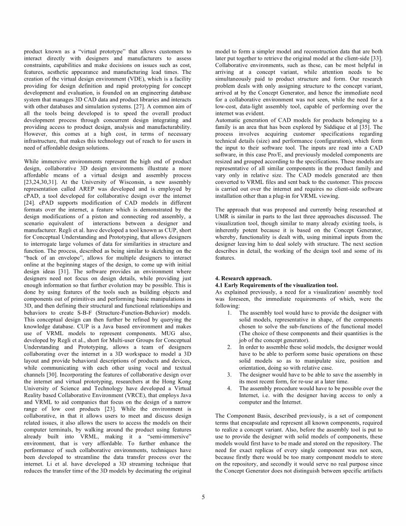
• Translation: • Free translation X • Free translation Y
Axis / translation increments X (cm.) Y (cm.) Z (cm.)
+5 +5 +5
+3 +3 +3 Increments
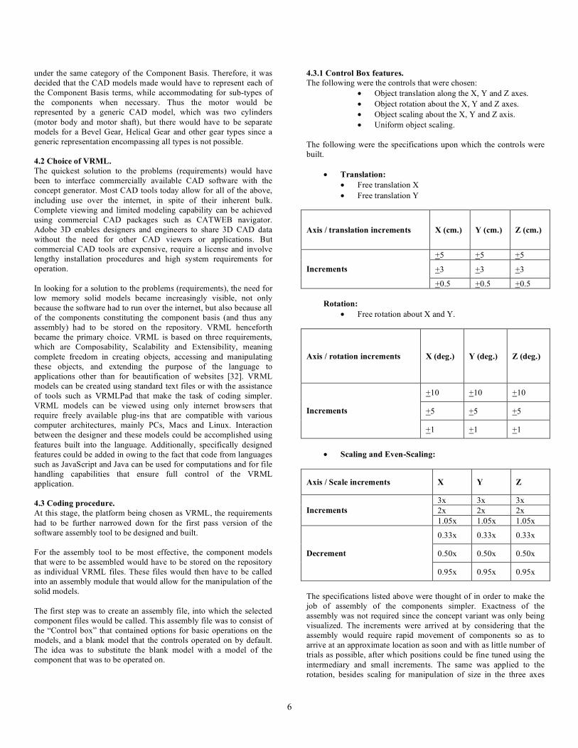
+0.5 +0.5 +0.5 Rotation:
• Free rotation about X and Y.
Axis / rotation increments X (deg.) Y (deg.) Z (deg.)
+10 +10 +10
+5 +5 +5 Increments
+1 +1 +1
• Scaling and Even-Scaling:
Axis / Scale increments X Y Z
3x 3x 3x 2x 2x 2x Increments 1.05x 1.05x 1.05x
0.33x 0.33x 0.33x
0.50x 0.50x 0.50x Decrement
0.95x 0.95x 0.95x
The specifications listed above were thought of in order to make the job of assembly of the components simpler. Exactness of the assembly was not required since the concept variant was only being visualized. The increments were arrived at by considering that the assembly would require rapid movement of components so as to arrive at an approximate location as soon and with as little number of trials as possible, after which positions could be fine tuned using the intermediary and small increments. The same was applied to the rotation, besides scaling for manipulation of size in the three axes
7
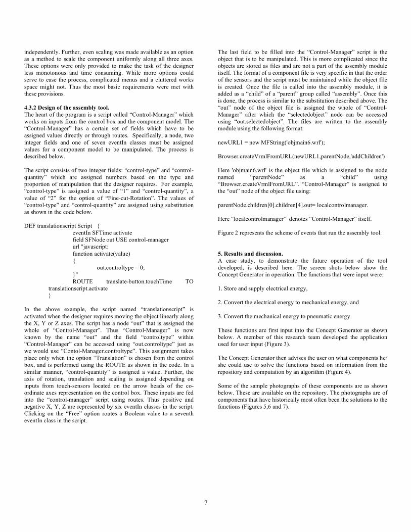
independently. Further, even scaling was made available as an option as a method to scale the component uniformly along all three axes. These options were only provided to make the task of the designer less monotonous and time consuming. While more options could serve to ease the process, complicated menus and a cluttered works space might not. Thus the most basic requirements were met with these provisions. 4.3.2 Design of the assembly tool. The heart of the program is a script called “Control-Manager” which works on inputs from the control box and the component model. The “Control-Manager” has a certain set of fields which have to be assigned values directly or through routes. Specifically, a node, two integer fields and one of seven eventIn classes must be assigned values for a component model to be manipulated. The process is described below. The script consists of two integer fields: “control-type” and “control-quantity” which are assigned numbers based on the type and proportion of manipulation that the designer requires. For example, “control-type” is assigned a value of “1” and “control-quantity”, a value of “2” for the option of “Fine-cut-Rotation”. The values of “control-type” and “control-quantity” are assigned using substitution as shown in the code below. DEF translationscript Script { eventIn SFTime activate field SFNode out USE control-manager url "javascript: function activate(value) { out.controltype = 0; }" ROUTE translate-button.touchTime TO translationscript.activate } In the above example, the script named “translationscript” is activated when the designer requires moving the object linearly along the X, Y or Z axes. The script has a node “out” that is assigned the whole of “Control-Manager”. Thus “Control-Manager” is now known by the name “out” and the field “controltype” within “Control-Manager” can be accessed using “out.controltype” just as we would use “Contol-Manager.controltype”. This assignment takes place only when the option “Translation” is chosen from the control box, and is performed using the ROUTE as shown in the code. In a similar manner, “control-quantity” is assigned a value. Further, the axis of rotation, translation and scaling is assigned depending on inputs from touch-sensors located on the arrow heads of the co-ordinate axes representation on the control box. These inputs are fed into the “control-manager” script using routes. Thus positive and negative X, Y, Z are represented by six eventIn classes in the script. Clicking on the “Free” option routes a Boolean value to a seventh eventIn class in the script.
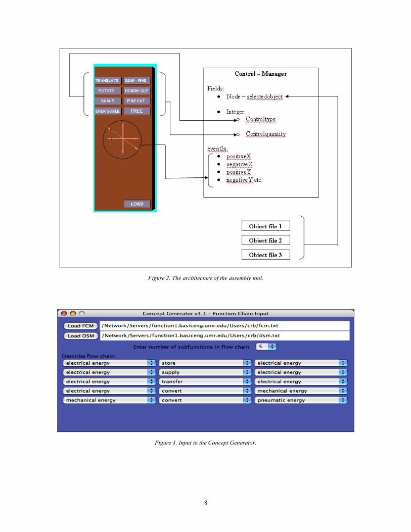
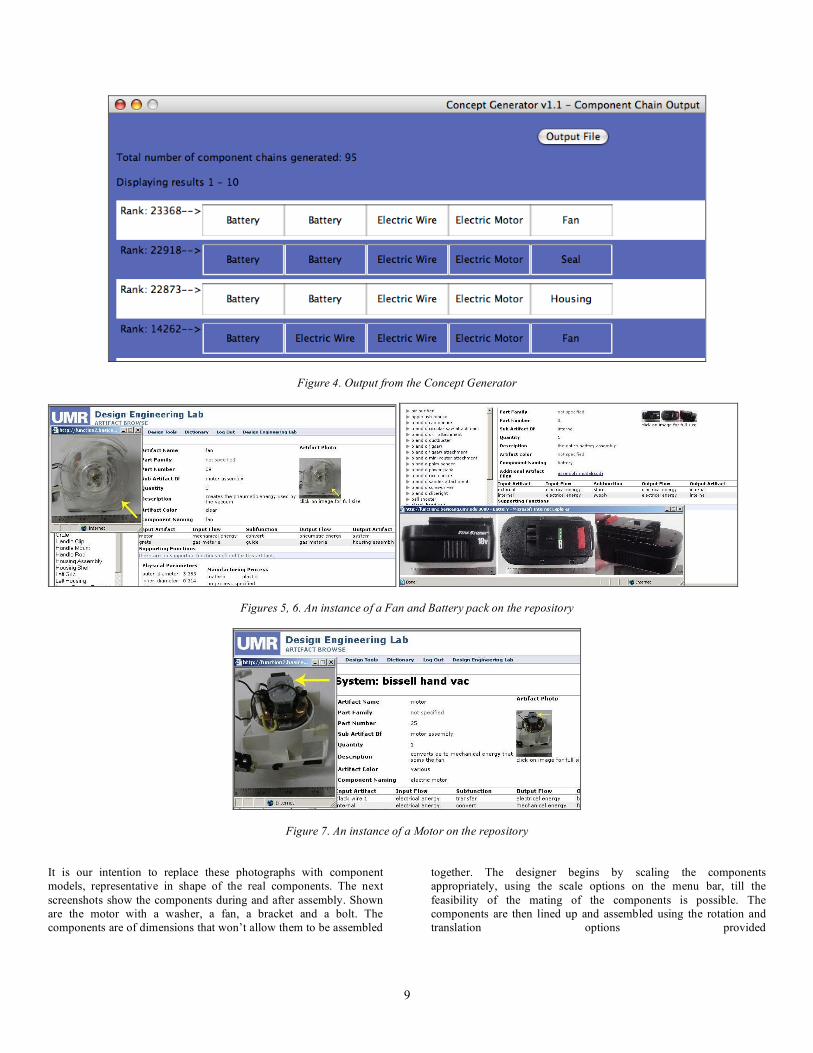
The last field to be filled into the “Control-Manager” script is the object that is to be manipulated. This is more complicated since the objects are stored as files and are not a part of the assembly module itself. The format of a component file is very specific in that the order of the sensors and the script must be maintained while the object file is created. Once the file is called into the assembly module, it is added as a “child” of a “parent” group called “assembly”. Once this is done, the process is similar to the substitution described above. The “out” node of the object file is assigned the whole of “Control-Manager” after which the “selectedobject” node can be accessed using “out.selectedobject”. The files are written to the assembly module using the following format: newURL1 = new MFString('objmain6.wrl'); Browser.createVrmlFromURL(newURL1,parentNode,'addChildren') Here 'objmain6.wrl' is the object file which is assigned to the node named “parentNode” as a “child” using “Browser.createVrmlFromURL”. “Control-Manager” is assigned to the “out” node of the object file using: parentNode.children[0].children[4].out= localcontrolmanager. Here “localcontrolmanager” denotes “Control-Manager” itself. Figure 2 represents the scheme of events that run the assembly tool. 5. Results and discussion. A case study, to demonstrate the future operation of the tool developed, is described here. The screen shots below show the Concept Generator in operation. The functions that were input were: 1. Store and supply electrical energy, 2. Convert the electrical energy to mechanical energy, and 3. Convert the mechanical energy to pneumatic energy. These functions are first input into the Concept Generator as shown below. A member of this research team developed the application used for user input (Figure 3). The Concept Generator then advises the user on what components he/ she could use to solve the functions based on information from the repository and computation by an algorithm (Figure 4). Some of the sample photographs of these components are as shown below. These are available on the repository. The photographs are of components that have historically most often been the solutions to the functions (Figures 5,6 and 7).
8
Figure 2. The architecture of the assembly tool.
Figure 3. Input to the Concept Generator.
9
Figure 4. Output from the Concept Generator
Figures 5, 6. An instance of a Fan and Battery pack on the repository
Figure 7. An instance of a Motor on the repository
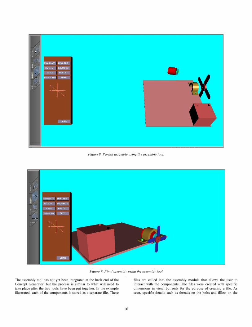
It is our intention to replace these photographs with component models, representative in shape of the real components. The next screenshots show the components during and after assembly. Shown are the motor with a washer, a fan, a bracket and a bolt. The components are of dimensions that won’t allow them to be assembled
together. The designer begins by scaling the components appropriately, using the scale options on the menu bar, till the feasibility of the mating of the components is possible. The components are then lined up and assembled using the rotation and translation options provided
10
Figure 8. Partial assembly using the assembly tool.
Figure 9. Final assembly using the assembly tool .
The assembly tool has not yet been integrated at the back end of the Concept Generator, but the process is similar to what will need to take place after the two tools have been put together. In the example illustrated, each of the components is stored as a separate file. These
files are called into the assembly module that allows the user to interact with the components. The files were created with specific dimensions in view, but only for the purpose of creating a file. As seen, specific details such as threads on the bolts and fillets on the

11
bracket, fan blade curvature etc. are absent, making these components only representative of the true models. These files can be subject to manipulation in size and orientation along all axes. The components vary from 12KB to 40KB in size. 6. Conclusion. This paper has presented our initial attempt to create a visualization tool to aid the designer in the conceptual design phase. The interactive tool will use the output of the Concept Generator software (which consists of a set of components that will connect together and solve the required functionality) as its starting point. Generalized representations for each of the component basis terms, stored as data-light VRML models, are initially arranged on screen to give the designer a visual representation of the proposed concept variant. These components can be manipulated by the designer to fine-tune the arrangement and to produce a more accurate visual representation of the concept variant. The VRML-based formulation of this visualization tool is well suited to the web based deployment of the Concept Generator, allowing quick interaction with the model and setting the stage for potential collaboration among geographically distributed designer. This initial, rough visual is expected to serve as a jumping off point for further concept variant refinements and other, potentially different, concept variants. 7. Future work. Immediate future work on includes refinement and improvement of the user interface and most importantly, saving of files for reuse by the designer at any time. Additionally, future work includes assembly methods that enable the designer to quickly explore different configurations. One such proposed method is to enable the design to indicate “snap” points on each part. These “snap” points would enable certain restrictions on the relative motion between two parts (as specified by the user). Then the user could “push” and “pull” the parts around in the work-space to find valid, and perhaps superior, configurations. For example, two components that have a transfer of fluid between them could have a simple contact snap between them, such as a water reservoir and a heater in a coffee maker, with a full 360 degrees of freedom. With this snap in place, the designer could push these parts around with other parts snapped in appropriate ways to find the most efficient layout for the coffee maker. Another future task is to enable the concept generator to suggest product architecture. The concept generator, in concert with the visualization tool, would produce an initial layout with proper orientations and sizing of components based on technical requirements. Examples of this include torque and RPM rating for motors and gear / shaft diameters etc. allowing the designer to realize a product that meets requirements on functionality while guiding physical structure. Detailed geometric representations are beyond the intent of the tool presented here. Nevertheless, once a designer is comfortable with the basic layout, they may wish to refine the fidelity of the geometric model to perform more accurate analysis. To enable this, the visualization tool needs to be linked to an underlying CAD repository with full CAD component models in it. In this case, each gear in the concept generator design repository would link to multiple gears in a CAD design repository with specific pitches, tooth geometries, etc. Similar in working principle to CUP, the components and their structural relationships could be used to query a CAD knowledge base for detailed models that could eventually develop into the final model for use. CAD based knowledge bases are foreseen to play a vital role in design engineering as a substitute to searching other time
consuming and non-repeatable sources such as engineering catalogues and corporate data [7]. Such a repository is in the making currently and the process of integrating the search for a match will soon be extended to sources other than just at UMR. Acknowledgements. This material is based upon work supported by the National Science Foundation under grant IIS-0307419. Any opinions, findings, and conclusions or recommendations presented in this paper are of the authors and do not necessarily reflect the views of the National Science Foundation. 8. References. [1] Bryant C, Stone R, McAdams D, Kurtoglu T, Campbell M. “Deriving a component basis for computational functional synthesis”. International Conference on Engineering Design, Melbourne 15-18 August, 2005. [2] Bryant C, McAdams D, Stone R, Kurtoglu T, Campbell M. “A computational technique for concept generation”. Proceedings of IDETC/CIE 2005, ASME 2005 International Design Engineering Technical Conferences & Computers and Information in Engineering Conference September 24-28, 2005, Long Beach, California USA DETC2005-85323 [3] Kurtoglu, T., Campbell, M., Gonzales, J., Bryant, C. and Stone, R., 2005, “Capturing Empirically Derived Design Knowledge for Creating Conceptual Design Configurations,” Proceedings of DETC2005, Long Beach, California, DETC05/DTM-84405. [4] Bohm M, Vucovich J, Stone R. “Capturing creativity: Using a design repository to drive concept innovation”. Proceedings of DETC '05 ASME 2005 Design Engineering Technical Conferences and Computers and Information in Engineering Conference Long Beach, California, USA, September 24 – 28, 2005 DETC2005-85105. [5] Bohm M, Stone R. “Product design support: exploring a design repository system”. Proceedings of IMECE '04 ASME International Mechanical Engineering Congress, Anaheim, California USA, November 13–19, 2004. IMECE2004-61746 [6] Antonsson, E. and J. Cagain, 2001, Formal Engineering Design Synthesis, Cambridge, University Press, New York, NY, 523. [7] Dixon, J. and C. Poli, 1995, Engineering Design and Design for Manufacturing: A Structured Approach, Field Stone, Conway, MA. [8] Hubka, V. and W. Ernst Eder, 1984, Theory of Technical Systems, Springer-Verlag, Berlin. [9] Otto, K. and K. Wood, 2001, Product Design: Techniques in Reverse Engineering, Systematic Design, and New Product Development, Prentice-Hall, New York. [10] Pahl, G. and W. Beitz, 1996, Engineering Design: A Systematic Approach, Springer Verlag. [11] Suh, N., 1998, The Principles of Design, Oxford University Press, New York. [12] Ullman, D. G., 2002, The Mechanical Design Process 3rd Edition, McGraw-Hill, Inc., New York.

12
[13] Ulrich, K. T. and S. D. Eppinger, 1995, Product Design and Development, McGraw-Hill, New York, NY. [14] Stone, R. and K. Wood, 2000, "Development of a Functional Basis for Design," Journal of Mechanical Design, 122 (4): 359-370. [15] Hirtz J, Stone R, McAdams D, Szykman S, Wood K. “A Functional Basis for Engineering Design: Reconciling and Evolving Previous Efforts”. Research in Engineering Design, 2002, Volume 13. Pg 65-82 [16] Bryant, C., Stone, R., McAdams, D., Kurtoglu, T. and Campbell, M., 2005, “Concept Generation from the Functional Basis of Design,” International Conference on Engineering Design, ICED 05, Melbourne, Australia. [17] Bohm, M., R. Stone and S. Szykman, 2005, "Enhancing Virtual Product Representations for Advanced Design Repository Systems," Journal of Computer and Information Science in Engineering, 5 (4): 360-372. [18] Stone R, Stock M, Wood K, Greer J. “Enumerating the component space: First steps toward a design naming convention for mechanical parts”. Proceedings of DETC ’03, 2003 ASME Design Engineering Technical Conferences and Computers and Information in Engineering Conference, September 2-6, 2003, Chicago, Illinois. DETC03/DTM-48666. [19] Ranga K, Gramoll K. “Design education over the internet using VRML”. Am. Soc. of Engineering Educ, (ASEE) 1999 Conf., June 20 - 23, 1999 Charlotte, NC, Session 2625 [20] Kamat V, Martinez J. “3D Visualization of simulated construction operations”. Proceedings of the 2000 Winter Simulation Conference. [21] Lund H, Hvidtfeldt M, Madsen J, Pedersen S. “VRML Visualization in a Surgery Planning and Diagnostics Application”. Proceedings of the fifth symposium on Virtual reality modeling language (Web3D-VRML)-2000, Monterey, California, United States. Pg 111-118. [22] Wallace D, Jakiela M. “Automated product concept design: Unifying aesthetics and engineering”. IEEE Computer Graphics and Applications, July 1993, pg 66-75. [23]Duffy V, Kan H Y, Su J C. “An internet virtual reality collaborative environment for effective product design”. Computers in Industry 45 (2001). Pg 197-213. [24] Shyamsundar N, Gadh R. “Internet-based collaborative product design with assembly features and virtual design spaces”. Computer-Aided Design 33 (2001). Pg 637-651. [25] Wallace D, Smyth S. “Towards the synthesis of aesthetic product form”. Proceedings of DETC'00 ASME 2000 Design Engineering Technical Conferences and Computers and Information in Engineering Conference Baltimore, Maryland, September 10-13, 2000 DETC2000/DTM-14554 [26] Cagan J, Agarwal M, Constantine K. “Influencing generative design thought continuous evaluation: associating costs with coffee maker shape grammar”. Artificial Intelligence for Engineering Design, Analysis and Manufacturing 1999!, 13, 253–275.
[27] Tseng M, Jiao J, Su C-J. “A framework of virtual design for product customization”. 0-7803-4192-9/97 1997 IEEE. [28] Vance J, Rehn G, Lemessi M, Dorozhkin D. “Integrating operations simulation results with an immersive virtual reality environment”. Proceedings of the 2004 Winter Simulation Conference. [29] Jayaram S, Wang Y, Jayaram U. “A Virtual Assembly Design Environment”. Proceedings of the IEEE Virtual Reality, 1999. [30] Cera C, Regli W, Braude I, Shapirstein Y, Foster C. “A collaborative 3D environment for authoring design semantics”. Graphics in Advanced computer aided design, IEEE Computer Graphics and Applications, May/ June 2002, pg 43-55. [31] Regli W, Cicirello V. “Managing digital libraries for computer aided design”. Computer-Aided Design 32 (2000). pg. 119–132
[32] Marrin C, Campbell B. “Teach yourself VRML in 21 days”. Publisher: Sams.net; Edition (January 1, 1997) ISBN: 1575211939
[33] Li W D, Lu W F, Cai Y L. “Geometric simplification to stream 3d models for collaborative product design”. Proceedings of IDETC/CIE 2005 ASME 2005 International Design Engineering Technical Conferences & Computers and Information in Engineering Conference September 24-28, 2005, Long Beach, California USA DETC2005-84834
[34]Zeng S, Kim E J, Mocko G M, Xiao A, Peak R, Mistree F. “Systematic design method for information modeling in cad/cae”. Proceedings of DETC.03 ASME 2003 Design Engineering Technical Conferences and Computers and Information in Engineering Conference Chicago, Illinois, USA, September 2-6, 2003 DETC2003/CIE-48241.
[35] Siddique Z, Reddy K B. “An agent based framework to automatically generate 3d cad models of customer specified products”. Proceedings of DETC.03 ASME 2003 Design Engineering Technical Conferences and Computers and Information in Engineering Conference Chicago, Illinois, USA, September 2-6, 2003 DETC2003/CIE-48227
[36] Terpenny P J, Mathew D. “Graphical modeling environment and supporting framework for functionbased conceptual design”. Proceedings of DETC’04 ASME 2004 Design Engineering Technical Conferences and Computers and Information in Engineering Conference September 28 October 2, 2004, Salt Lake City, Utah USA DETC2004-57492 [37] Zoltán Rusák, Imre Horváth. “A study of model representations for shape conceptualization”. Proceedings of IDETC/CIE 2005 ASME 2005 International Design Engineering Technical Conferences & Computers and Information in Engineering Conference September 24-28, 2005, Long Beach, California USA DETC2005-84662.