Embed Size (px)
Citation preview
Visuohaptic Borescope Inspection Simulation Training: ModelingMulti-Point Collision Detection/Response and Evaluating Skills TransferDeepak Vembar, Andrew Duchowski∗
School of ComputingClemson University
Melissa Paul, Anand GramopadhyeIndustrial Engineering
Clemson University
Carl WashburnAircraft Maintenance Program
Greenville Technical College
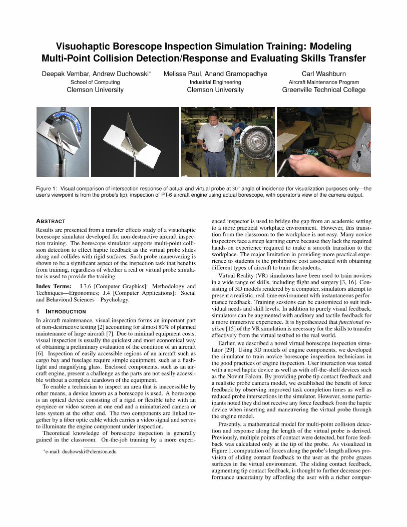
Figure 1: Visual comparison of intersection response of actual and virtual probe at 30◦ angle of incidence (for visualization purposes only—theuser’s viewpoint is from the probe’s tip); inspection of PT-6 aircraft engine using actual borescope, with operator’s view of the camera output.
ABSTRACT
Results are presented from a transfer effects study of a visuohapticborescope simulator developed for non-destructive aircraft inspec-tion training. The borescope simulator supports multi-point colli-sion detection to effect haptic feedback as the virtual probe slidesalong and collides with rigid surfaces. Such probe maneuvering isshown to be a significant aspect of the inspection task that benefitsfrom training, regardless of whether a real or virtual probe simula-tor is used to provide the training.
Index Terms: I.3.6 [Computer Graphics]: Methodology andTechniques—Ergonomics; J.4 [Computer Applications]: Socialand Behavioral Sciences—Psychology.
1 INTRODUCTION
In aircraft maintenance, visual inspection forms an important partof non-destructive testing [2] accounting for almost 80% of plannedmaintenance of large aircraft [7]. Due to minimal equipment costs,visual inspection is usually the quickest and most economical wayof obtaining a preliminary evaluation of the condition of an aircraft[6]. Inspection of easily accessible regions of an aircraft such ascargo bay and fuselage require simple equipment, such as a flash-light and magnifying glass. Enclosed components, such as an air-craft engine, present a challenge as the parts are not easily accessi-ble without a complete teardown of the equipment.
To enable a technician to inspect an area that is inaccessible byother means, a device known as a borescope is used. A borescopeis an optical device consisting of a rigid or flexible tube with aneyepiece or video screen at one end and a miniaturized camera orlens system at the other end. The two components are linked to-gether by a fiber optic cable which carries a video signal and servesto illuminate the engine component under inspection.
Theoretical knowledge of borescope inspection is generallygained in the classroom. On-the-job training by a more experi-
∗e-mail: [email protected]
enced inspector is used to bridge the gap from an academic settingto a more practical workplace environment. However, this transi-tion from the classroom to the workplace is not easy. Many noviceinspectors face a steep learning curve because they lack the requiredhands-on experience required to make a smooth transition to theworkplace. The major limitation in providing more practical expe-rience to students is the prohibitive cost associated with obtainingdifferent types of aircraft to train the students.
Virtual Reality (VR) simulators have been used to train novicesin a wide range of skills, including flight and surgery [3, 16]. Con-sisting of 3D models rendered by a computer, simulators attempt topresent a realistic, real-time environment with instantaneous perfor-mance feedback. Training sessions can be customized to suit indi-vidual needs and skill levels. In addition to purely visual feedback,simulators can be augmented with auditory and tactile feedback fora more immersive experience. It is hypothesized that functional re-alism [15] of the VR simulation is necessary for the skills to transfereffectively from the virtual testbed to the real world.
Earlier, we described a novel virtual borescope inspection simu-lator [29]. Using 3D models of engine components, we developedthe simulator to train novice borescope inspection technicians inthe good practices of engine inspection. User interaction was testedwith a novel haptic device as well as with off-the-shelf devices suchas the Novint Falcon. By providing probe tip contact feedback anda realistic probe camera model, we established the benefit of forcefeedback by observing improved task completion times as well asreduced probe intersections in the simulator. However, some partic-ipants noted they did not receive any force feedback from the hapticdevice when inserting and maneuvering the virtual probe throughthe engine model.
Presently, a mathematical model for multi-point collision detec-tion and response along the length of the virtual probe is derived.Previously, multiple points of contact were detected, but force feed-back was calculated only at the tip of the probe. As visualized inFigure 1, computation of forces along the probe’s length allows pro-vision of sliding contact feedback to the user as the probe grazessurfaces in the virtual environment. The sliding contact feedback,augmenting tip contact feedback, is thought to further decrease per-formance uncertainty by affording the user with a richer compar-
ison to expected kinesthetic sensations, and thus hypothesized toreduce functional task difficulty [17]. We do not test this hypothesisdirectly, however.
While sliding contact is tacitly assumed to enrich haptic feed-back, in this paper we focus on the evaluation of training trans-fer effects on real world task performance. Prior evaluation of theborescope simulator was limited to representative inspection tasksin the simulator. We did not perform any evaluation of task per-formance during an actual engine inspection. Here, quantitativeand qualitative measures are reported from novice students inspect-ing a PT6 engine after undergoing one of three training methods:classroom-only training, simulator training, or hands-on trainingwith the video borescope. Results indicate that the psychomotorskills required for maneuvering the borescope probe through theengine can be successfully obtained through simulator training.
2 PHYSICALLY-BASED PROBE MODEL
While graphics rendering focuses on the visual appearance of themodel, by computing appropriate force/torque interaction, hapticrendering simulates force feedback to allow the human operatorto feel the geometry, surface, and material properties of the ob-ject. There are two major points of asymmetry between haptic andgraphics rendering: collision detection and rate of dynamic simu-lation. Unlike graphics rendering which only needs to model ob-ject deformation to “look” realistic, haptic rendering has to be builtupon a more accurate physics-based model. While real-time up-date rates for graphics rendering are about 30-60 frames per second,smooth haptic rendering requires an update rate of almost 1 KHz.
In haptic interface design, the deciding factor in choosing thebest collision algorithm is the speed of calculation to determinewhether a collision has occurred. Inter and intra-object collisionsplay an important role in the overall behavior of the interacting ob-jects in a simulation. The choice of the contact model, single pointversus multi-point contact detection, and external forces such asstatic and dynamic friction, influence the post-impact motion of theinteracting objects. Quick changes in haptic forces when objects in-tersect can cause artificial growth of energy and lead to instabilitiesof the simulation [27].
2.1 Prior workPrior work in the medical simulation community has led to the de-velopment of fast, scalable, multi-object, multi-point collision sim-ulation and response algorithms [4]. Intersections of the borescopeprobe with the engine can occur at multiple points along the in-serted length. Probe deformations occur due to collisions with theengine, and the amount of deformation is dependent on the positionwithin the engine, force applied at the point of incidence, as wellas the angle of incidence of the probe at the point of contact. Un-like medical procedures, which use a catheter, such as in vascularand cardio-thoracic surgery, interaction of the borescope probe withthe engine consists of a semi-flexible body interacting with a rigidbody. Instead of computing elastic and deformation forces experi-enced by the catheter due to collision with soft tissues, computationof deformations can be limited to the interaction of the semi-flexibleprobe with rigid surfaces.
Prior work, especially in radiology and vascular surgery [5, 24],has resulted in visual and behaviorally realistic models for simu-lating catheters, guidewires and surgical threads. Deformable ob-jects have been simulated using physically-based mass-spring mod-els following Newtonian Laws of motion. The catheter or surgicalthread is modeled as a linear system of point masses connectedby linear and torsional springs between two adjacent points. Us-ing explicit or implicit numerical integration, the velocities andpositions of each point mass are computed over the duration ofthe simulation. Since collision detection is computationally ex-pensive, methods such as bounding spheres, axis-aligned bounding
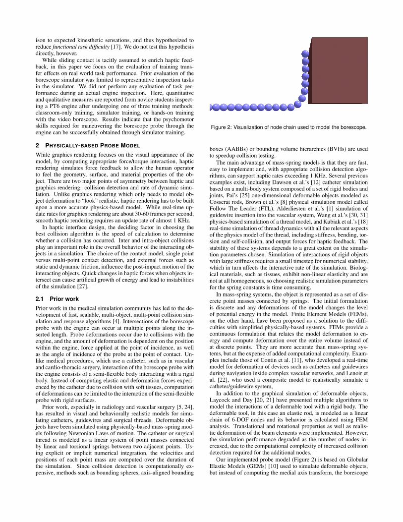
Figure 2: Visualization of node chain used to model the borescope.
boxes (AABBs) or bounding volume hierarchies (BVHs) are usedto speedup collision testing.
The main advantage of mass-spring models is that they are fast,easy to implement and, with appropriate collision detection algo-rithms, can support haptic rates exceeding 1 KHz. Several previousexamples exist, including Dawson et al.’s [12] catheter simulationbased on a multi-body system composed of a set of rigid bodies andjoints, Pai’s [25] one-dimensional deformable objects modeled asCosserat rods, Brown et al.’s [8] physical simulation model calledFollow The Leader (FTL), Alderliesten et al.’s [1] simulation ofguidewire insertion into the vascular system, Wang et al.’s [30, 31]physics-based simulation of a thread model, and Kubiak et al.’s [18]real-time simulation of thread dynamics with all the relevant aspectsof the physics model of the thread, including stiffness, bending, tor-sion and self-collision, and output forces for haptic feedback. Thestability of these systems depends to a great extent on the simula-tion parameters chosen. Simulation of interactions of rigid objectswith large stiffness requires a small timestep for numerical stability,which in turn affects the interactive rate of the simulation. Biolog-ical materials, such as tissues, exhibit non-linear elasticity and arenot at all homogeneous, so choosing realistic simulation parametersfor the spring constants is time consuming.
In mass-spring systems, the object is represented as a set of dis-crete point masses connected by springs. The initial formulationis discrete and any deformations of the model changes the levelof potential energy in the model. Finite Element Models (FEMs),on the other hand, have been proposed as a solution to the diffi-culties with simplified physically-based systems. FEMs provide acontinuous formulation that relates the model deformation to en-ergy and compute deformation over the entire volume instead ofat discrete points. They are more accurate than mass-spring sys-tems, but at the expense of added computational complexity. Exam-ples include those of Contin et al. [11], who developed a real-timemodel for deformation of devices such as catheters and guidewiresduring navigation inside complex vascular networks, and Lenoir etal. [22], who used a composite model to realistically simulate acatheter/guidewire system,
In addition to the graphical simulation of deformable objects,Laycock and Day [20, 21] have presented multiple algorithms tomodel the interactions of a deformable tool with a rigid body. Thedeformable tool, in this case an elastic rod, is modeled as a linearchain of 6-DOF nodes and its behavior is calculated using FEManalysis. Translational and rotational properties as well as realis-tic deformation of the beam elements were implemented. However,the simulation performance degraded as the number of nodes in-creased, due to the computational complexity of increased collisiondetection required for the additional nodes.
Our implemented probe model (Figure 2) is based on GlobularElastic Models (GEMs) [10] used to simulate deformable objects,but instead of computing the medial axis transform, the borescope
Guide tube
Probe articulationcontrolled by user
Foremost nodeNodes in guide tube, fixed
Nodes controlling probe articulation
Nodes used in dynamic simulation
Direction of probe motion
Aft nodes
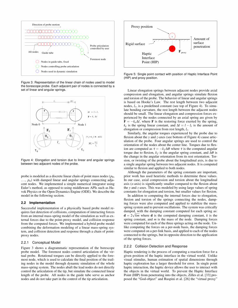
Figure 3: Representation of the linear chain of nodes used to modelthe borescope probe. Each adjacent pair of nodes is connected by aset of linear and angular springs.
lk e
r
F =
∆l = l − l
τi
=l r
iF
τi π/2 )( θk=
f
0F 1F
τ τ 1
0
0
1θ θ
l r
∆l r l
Node 1l
FF
Node 0
∆
Figure 4: Elongation and torsion due to linear and angular springsbetween two adjacent nodes of the probe.
probe is modeled as a discrete linear chain of point mass nodes (p0,. . . , pn) with damped linear and angular springs connecting adja-cent nodes. We implemented a simple numerical integrator usingEuler’s method, as opposed to using middleware APIs such as Ha-vok Physics or the Open Dynamics Engine (ODE). We describe themodel in the following section.
2.2 ImplementationSuccessful implementation of a physically based probe model re-quires fast detection of collisions, computation of interacting forcesfrom an internal mass-spring model of the simulation as well as ex-ternal forces due to the point-proxy model, and collision responsefrom the computed forces. We implemented a hybrid probe modelcombining the deformation modeling of a linear mass-spring sys-tem, and collision detection and response through a chain of point-proxy nodes.
2.2.1 Conceptual ModelFigure 3 shows a diagrammatic representation of the borescopeprobe model. The foremost nodes control articulation of the vir-tual probe. Rotational torques can be directly applied to the fore-most node, which is used to calculate the final position of the trail-ing nodes in the model through dynamic simulation of the wholemass-spring system. The nodes abaft the lead nodes do not directlycontrol the articulation of the tip, but simulate the connected linearlength of the probe. Aft nodes in the guide tube serve as anchornodes and do not take part in the control of the tip articulation.
Proxy position
Rigid surface
Haptic
Interface
Point (HIP)
F
Amount of surfacepenetration
proxy
Figure 5: Single point contact with position of Haptic Interface Point(HIP) and proxy position.
Linear elongation springs between adjacent nodes provide axialcompression and elongation, and angular springs simulate flexionand torsion of the probe. The behavior of linear and angular springsis based on Hooke’s Law. The rest length between two adjacentnodes, lr, is a predefined constant (see top of Figure 4). To simu-late bending curvature, the rest length between the adjacent nodesshould be small. The linear elongation and compression forces ex-perienced by the nodes connected by an axial spring are given byF = −ke∆l, where F is the restoring force exerted by the spring,ke is the spring linear constant, and ∆l = l − lr is the amount ofelongation or compression from rest length, lr.
Similarly, the angular torques experienced by the probe due toflexion about the y and z-axes (see bottom of Figure 4) cause artic-ulation of the probe. Four angular springs are used to control theorientation of the nodes about the center line. Torques due to flex-ion are computed as τ = −k f ∆θ where τ is the computed angulartorque due to flexion, k f is the angular spring constant, and ∆θ isthe change in the angular orientation from its rest orientation. Tor-sion, or twisting of the probe about the longitudinal axis, is due toa single angular spring between two adjacent nodes. It is computedsimilar to flexion and applied to both nodes.
Although the parameters of the spring constants are important,prior work has used heuristic methods to determine these values.In our case, axial compression and torsion about the longitudinalaxis (x-axis) is significantly smaller compared to the flexion aboutthe y and z-axes. This was modeled by using large values of springconstants for elongation and torsion, but smaller values for flexion.
In addition to computing the internal forces due to elongation,flexion and torsion of the springs connecting the nodes, damp-ing forces were also computed and applied to stabilize the mass-spring system and to prevent oscillations. The system was criticallydamped, with the damping constant computed for each spring as:d = 2
√km where d is the computed damping constant, k is the
spring constant, and m is the mass of the node. Damping forceswere computed for each of the three springs acting on the node. Un-like computing the forces on a per-node basis, the damping forceswere computed on a per-link basis, and applied to each of the nodesconnected to the springs, but in opposite direction to the applicationof the spring forces.
2.2.2 Collision Detection and Response
Haptic rendering is the process of computing a reaction force for agiven position of the haptic interface in the virtual world. Unlikevisual stimulus, human estimation of spatial dimensions throughhaptic exploration has a larger threshold for error. In single pointhaptic interaction, the haptic device allows the user to interact withthe objects in the virtual world. To prevent the Haptic InterfacePoint (HIP) from penetrating into the objects, Zilles et al. [33] pro-posed the “God-object” and Ruspini et al. [26] the “virtual proxy”
Direction of probe motion
Free moving node
Proxy and HIP co−located
Node in contact with
surface
Actual postion of node
(HIP)
Computed proxy position
constrained to the surface
Computed
haptic forces
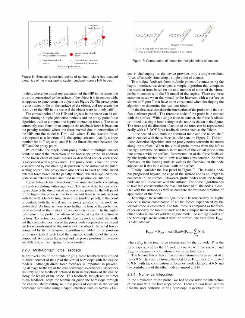
Figure 6: Simulating multiple points of contact, taking into accountdynamics of the mass-spring system and point-proxy HIP forces.
models, where the visual representation of the HIP in the scene, theproxy, is constrained to the surface of the object it is in contact with,as opposed to penetrating the object (see Figure 5). The proxy pointis constrained to lie on the surface of the object, and represents theposition of the HIP in the scene if the object were infinitely stiff.
The contact point of the HIP and objects in the scene can be ob-tained through simple geometric methods and the proxy-point forcealgorithm used to compute the haptic interaction forces. The mostcommonly used function to compute the feedback force is based onthe penalty method, where the force exerted due to penetration ofthe HIP into the model is F = −kδ , where F, the reaction force,is computed as a function of k, the spring constant (usually a largenumber for stiff objects), and δ is the linear distance between theHIP and the proxy point.
We extended the single point-proxy method to multiple contactpoints to model the interaction of the borescope probe. In additionto the linear chain of point masses as described earlier, each nodeis associated with a proxy node. The proxy node is used for probevisualization by constraining its position to the surface of the inter-secting object. The proxy node also serves to exert an unbalancedexternal force based on the penalty method, which is applied to thenode as an external force and used in the position calculation.
Figure 6 depicts the interaction of the simulated probe consistingof 5 nodes colliding with a rigid wall. The arrow at the bottom of thefigure depicts the direction of motion of the probe. In the left panelof the figure, the probe is free to move and there is no intersectionwith the wall. On detecting intersection (middle panel), at the pointof contact, both the actual and the proxy position of the node areco-located. As long as there is no further motion of the probe, theforce exerted at the contact proxy position is zero. In the right-most panel, the probe has advanced further along the direction ofmotion. The actual position of the leading node is inside the wall,but the computed position of the proxy node (depicted as a coloredcircle) is constrained to the surface of the object. External forcescomputed by the proxy-point algorithm are added to the positionof the node (filled circle) and the dynamic simulation of the probecomputed. As long as the actual and the proxy position of the nodeare different, a linear spring force is exerted.
2.2.3 Multi-Contact Force Feedback
In prior versions of the simulator [29], force feedback was limitedto direct contact of the tip of the virtual borescope with the enginemodels. Although direct force feedback is important in prevent-ing damage to the tip of the real borescope, experienced inspectorsalso rely on the feedback obtained from intersections of the enginealong the length of the probe. This feedback, though not as directas tip feedback, helps the technician guide the borescope throughthe engine. Representing multiple points of contact in the virtualborescope simulator using a haptic interface such as Novint’s Fal-
Direction of probe motion
Free moving node, proxy and HIP co−located
Node in contact with arrow depicting direction of force feedback
Figure 7: Computation of forces for multiple points of contact.
con is challenging, as the device provides only a single resultantforce, effectively simulating a single point of contact.
To simulate feedback from multiple points of contact using thehaptic interface, we developed a simple algorithm that computesthe resultant force based on the total number of nodes of the virtualprobe in contact with the 3D model of the engine. There are threecommon cases when the virtual probe interacts with a surface asshown in Figure 7 that have to be considered when developing thealgorithm to determine the resultant force.
In the first case, consider the interaction of the probe with the sur-face (leftmost panel). The foremost node of the probe is in contactwith the surface. With a single node in contact, the force feedbackis limited to a single force acting on the node as shown in the figure.The force and the direction of action of the force can be representedeasily with a 3-DOF force feedback device such as the Falcon.
In the second case, both the foremost node and the nodes abaftare in contact with the surface (middle panel in Figure 7). The col-lision detection algorithm and the proxy nodes constrain the nodesalong the surface. When the virtual probe moves from the left tothe right towards the surface, more nodes of the virtual probe comeinto contact with the surface. Representation of the force feedbackby the haptic device has to now take into consideration the forcefeedback on the leading node as well as the feedback on the nodeadjacent to it that is in contact with the surface.
Finally, consider the last panel in Figure 7. The leading nodehas progressed beyond the edge of the surface and is no longer incontact with the surface. However, probe nodes abaft the leadingnode are still in contact with the surface. The force algorithm hasto take into consideration the resultant force of all the nodes in con-tact with the surface, as well as compute the resultant direction ofapplication of the force.
To compute the resultant single force to be rendered by the hapticdevice, a linear combination of all the forces experienced by thevirtual probe is calculated. The total force is computed as the forceexperienced by the foremost node and the clamped linear sum of theother nodes in contact with the engine model. Assuming n nodes ofthe borescope are in contact with the surface, the total force Ftotalis calculated as:
Ftotal = Ftip +max(0,min(Fmax,n
∑i=0
Fi)),
where Ftip is the total force experienced by the tip node, Fi is theforce experienced by the ith node in contact with the surface, andFmax is maximum contribution towards the total force.
The Novint Falcon has a maximum continuous force output of 2lbs or 8 N. The contribution of the total force Ftotal was thus limitedto 8 N, with the contribution of foremost node clamped at 6 N andthe contribution of the other nodes clamped at 2 N.
2.2.4 Numerical IntegrationIn the simulation of the probe, we had to consider the interactionof the user with the borescope probe. There are two basic actionsthat the user performs during borescope inspection: insertion of
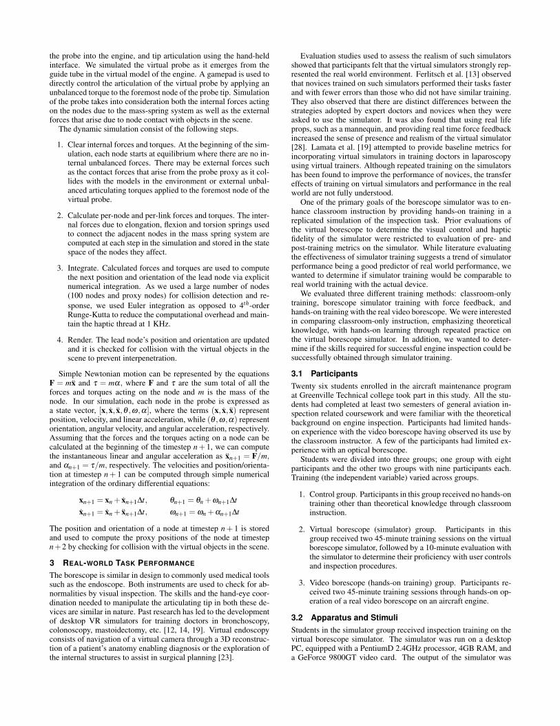
the probe into the engine, and tip articulation using the hand-heldinterface. We simulated the virtual probe as it emerges from theguide tube in the virtual model of the engine. A gamepad is used todirectly control the articulation of the virtual probe by applying anunbalanced torque to the foremost node of the probe tip. Simulationof the probe takes into consideration both the internal forces actingon the nodes due to the mass-spring system as well as the externalforces that arise due to node contact with objects in the scene.
The dynamic simulation consist of the following steps.
1. Clear internal forces and torques. At the beginning of the sim-ulation, each node starts at equilibrium where there are no in-ternal unbalanced forces. There may be external forces suchas the contact forces that arise from the probe proxy as it col-lides with the models in the environment or external unbal-anced articulating torques applied to the foremost node of thevirtual probe.
2. Calculate per-node and per-link forces and torques. The inter-nal forces due to elongation, flexion and torsion springs usedto connect the adjacent nodes in the mass spring system arecomputed at each step in the simulation and stored in the statespace of the nodes they affect.
3. Integrate. Calculated forces and torques are used to computethe next position and orientation of the lead node via explicitnumerical integration. As we used a large number of nodes(100 nodes and proxy nodes) for collision detection and re-sponse, we used Euler integration as opposed to 4th-orderRunge-Kutta to reduce the computational overhead and main-tain the haptic thread at 1 KHz.
4. Render. The lead node’s position and orientation are updatedand it is checked for collision with the virtual objects in thescene to prevent interpenetration.
Simple Newtonian motion can be represented by the equationsF = mx and τ = mα, where F and τ are the sum total of all theforces and torques acting on the node and m is the mass of thenode. In our simulation, each node in the probe is expressed asa state vector, [x, x, x,θ ,ω,α], where the terms (x, x, x) representposition, velocity, and linear acceleration, while (θ ,ω,α) representorientation, angular velocity, and angular acceleration, respectively.Assuming that the forces and the torques acting on a node can becalculated at the beginning of the timestep n + 1, we can computethe instantaneous linear and angular acceleration as xn+1 = F/m,and αn+1 = τ/m, respectively. The velocities and position/orienta-tion at timestep n + 1 can be computed through simple numericalintegration of the ordinary differential equations:
xn+1 = xn + xn+1∆t, θn+1 = θn +ωn+1∆txn+1 = xn + xn+1∆t, ωn+1 = ωn +αn+1∆t
The position and orientation of a node at timestep n + 1 is storedand used to compute the proxy positions of the node at timestepn+2 by checking for collision with the virtual objects in the scene.
3 REAL-WORLD TASK PERFORMANCE
The borescope is similar in design to commonly used medical toolssuch as the endoscope. Both instruments are used to check for ab-normalities by visual inspection. The skills and the hand-eye coor-dination needed to manipulate the articulating tip in both these de-vices are similar in nature. Past research has led to the developmentof desktop VR simulators for training doctors in bronchoscopy,colonoscopy, mastoidectomy, etc. [12, 14, 19]. Virtual endoscopyconsists of navigation of a virtual camera through a 3D reconstruc-tion of a patient’s anatomy enabling diagnosis or the exploration ofthe internal structures to assist in surgical planning [23].
Evaluation studies used to assess the realism of such simulatorsshowed that participants felt that the virtual simulators strongly rep-resented the real world environment. Ferlitsch et al. [13] observedthat novices trained on such simulators performed their tasks fasterand with fewer errors than those who did not have similar training.They also observed that there are distinct differences between thestrategies adopted by expert doctors and novices when they wereasked to use the simulator. It was also found that using real lifeprops, such as a mannequin, and providing real time force feedbackincreased the sense of presence and realism of the virtual simulator[28]. Lamata et al. [19] attempted to provide baseline metrics forincorporating virtual simulators in training doctors in laparoscopyusing virtual trainers. Although repeated training on the simulatorshas been found to improve the performance of novices, the transfereffects of training on virtual simulators and performance in the realworld are not fully understood.
One of the primary goals of the borescope simulator was to en-hance classroom instruction by providing hands-on training in areplicated simulation of the inspection task. Prior evaluations ofthe virtual borescope to determine the visual control and hapticfidelity of the simulator were restricted to evaluation of pre- andpost-training metrics on the simulator. While literature evaluatingthe effectiveness of simulator training suggests a trend of simulatorperformance being a good predictor of real world performance, wewanted to determine if simulator training would be comparable toreal world training with the actual device.
We evaluated three different training methods: classroom-onlytraining, borescope simulator training with force feedback, andhands-on training with the real video borescope. We were interestedin comparing classroom-only instruction, emphasizing theoreticalknowledge, with hands-on learning through repeated practice onthe virtual borescope simulator. In addition, we wanted to deter-mine if the skills required for successful engine inspection could besuccessfully obtained through simulator training.
3.1 ParticipantsTwenty six students enrolled in the aircraft maintenance programat Greenville Technical college took part in this study. All the stu-dents had completed at least two semesters of general aviation in-spection related coursework and were familiar with the theoreticalbackground on engine inspection. Participants had limited hands-on experience with the video borescope having observed its use bythe classroom instructor. A few of the participants had limited ex-perience with an optical borescope.
Students were divided into three groups; one group with eightparticipants and the other two groups with nine participants each.Training (the independent variable) varied across groups.
1. Control group. Participants in this group received no hands-ontraining other than theoretical knowledge through classroominstruction.
2. Virtual borescope (simulator) group. Participants in thisgroup received two 45-minute training sessions on the virtualborescope simulator, followed by a 10-minute evaluation withthe simulator to determine their proficiency with user controlsand inspection procedures.
3. Video borescope (hands-on training) group. Participants re-ceived two 45-minute training sessions through hands-on op-eration of a real video borescope on an aircraft engine.
3.2 Apparatus and StimuliStudents in the simulator group received inspection training on thevirtual borescope simulator. The simulator was run on a desktopPC, equipped with a PentiumD 2.4GHz processor, 4GB RAM, anda GeForce 9800GT video card. The output of the simulator was
presented on a 19′′ LCD monitor placed in front of the participant ina 1024×768 window. The visual stimulus provided to participantsconsisted of a polygonal model of the PT-6 engine, modeled andtextured in Maya. The rendering of the engine components and thehaptic feedback calculations was handled by CHAI libraries [9],an open-source API for graphical and haptic rendering. The probemodel implemented allowed the user to rotate the virtual camerain a hemisphere about the probe’s axis. Camera articulation of thevirtual probe was controlled by an off-the-shelf gamepad. An off-the-shelf Novint Falcon was used both for controlling the amount ofvirtual probe insertion into the 3D engine as well as to provide forcefeedback of the contact forces experienced by the virtual probe.
The students in the hands-on training group received inspectiontraining using the Olympus video borescope. A representative en-gine of a PT6 aircraft was dismantled to expose the hot section com-ponents consisting of the stator and rotor, as shown in Figure 1. Aguide tube was inserted into the fuel injection manifold at the topof the engine casing to allow easy insertion of the borescope intothe engine and facilitate inspection of the rotor. An experiencedborescope inspector was present to provide instruction and guid-ance on the best practices while inspecting with the borescope.
3.3 Procedure
At the beginning of the experiment, the participants filled out a de-mographic questionnaire on their experience with training simula-tors and the video borescope. The experiment was carried out overthree days to prevent fatigue and avoid influencing the results of theexperimental evaluation.
On day 1, the control group received no training on the simula-tor or the actual engine. The simulator group was provided trainingwith the virtual borescope, with a focus on familiarizing the partic-ipants with the articulation and insertion controls of the simulator.Participants were first introduced to the simulator and the use of thegamepad and the Falcon to control the virtual probe. Next, partici-pants spent approximately 45 minutes interacting with the simula-tor and getting used to the articulation controls. In addition to psy-chomotor skills training, we also provided good practices inspec-tion training by having the participants inspect the engine model ina systematic fashion. Numbered textures on the engine model em-phasized this aspect of training, with arrows prompting successivestages of inspection. At the end of the familiarization phase, partic-ipants were tested on their progress by performing a simulated taskof inspecting 15 rotor blades for defects. Quantitative measures oftime to complete the task and the total number of probe tip inter-sections with the engine model were collected for offline analysis.
The training provided to the borescope training group consistedof introduction to the video borescope, a brief summary of control-ling the probe tip with the articulation joystick and good practicesin borescope inspection. On completion of these steps, the partici-pants used the borescope and performed a 45 minute inspection ona PT-6 engine. The engine was pristine and did not have any de-fects, as we wanted the participants to become accustomed to theinterface as opposed to the task of defect detection.
On day 2, the steps followed were similar to day 1 for all threegroups with a few minor changes. In addition to providing goodpractices inspection for the simulator group, they were also pro-vided training to detect common defects such as cracks and corro-sion in the engine. Defect textures were developed and mapped onthe engine model to provide a brief overview of different enginedefects. At the end of the simulator training, quantitative data wascollected to compare the influence (if any) of longer training dura-tions on participants’ performance over the two days. There wereno changes to the training provided to the other two groups.
On day 3, all three groups were tested on a PT-6 engine using thevideo borescope. The engine used in this study differed from theone used for training the hands-on group in order to reduce learn-
ing effects. Random blades were painted with a white X simulatingrotor defects (recall we are focusing on probe usage training, not oninspection search and decision making). As the control and simu-lator groups were using the video borescope for the first time, theywere provided a 10 minute introduction to the video borescope andits articulation controls.
The inspection process consisted of participants inserting theborescope probe into the engine through the guide tube and ma-neuvering the borescope probe through the engine stators to obtaina good view of the rotor. Once the participant had a clear view ofthe leading edge and the base of the rotor blades, the inspectiontask consisted of looking for the painted markers on the blades. Anaccomplice manually rotated the engine to turn the rotor so thatthe participant could concentrate on borescope probe manipulationand controlling the camera articulation along with defect detection.Once the participant completed inspecting all 58 blades of the rotor,they were instructed to complete the inspection task by withdraw-ing the probe from the engine.
3.4 Experimental Design and Data CollectedA between-subjects completely random experimental design wasused to study the transfer effects of simulator training. The 26participants were randomly assigned to one of the three traininggroups. Training condition served as the independent variable. Per-formance data collected was time taken to complete the task, brokendown into 4 intervals: (1) inserting the borescope probe through theguide tube into the engine, (2) maneuvering the probe through thestator to obtain a clear view of the rotor blades for inspection, (3)systematically inspecting the blades for simulated defects, and (4)withdrawing the borescope probe from the engine.
The control group was expected to yield the the largest meaninspection times, compared to the simulator and hands-on traininggroups. The simulator and borescope training groups were expectedto achieve similar performance due to improved skill levels com-pared to classroom-only training group.
The virtual borescope group had additional performance andsubjective data collected at the end of each individual training ses-sions. The total time to complete the simulator inspection and thenumber of intersections of the virtual camera with the engine modelwere collected and analyzed to determine the effects of repeatedtraining on task performance in the simulator. On completion ofthe training, the participants filled out a modified Witmer-SingerPresence Questionnaire [32], with responses to the questionnaireon a 7-point Likert scale, with 1 being most negative, 4 neutral, and7 most positive.
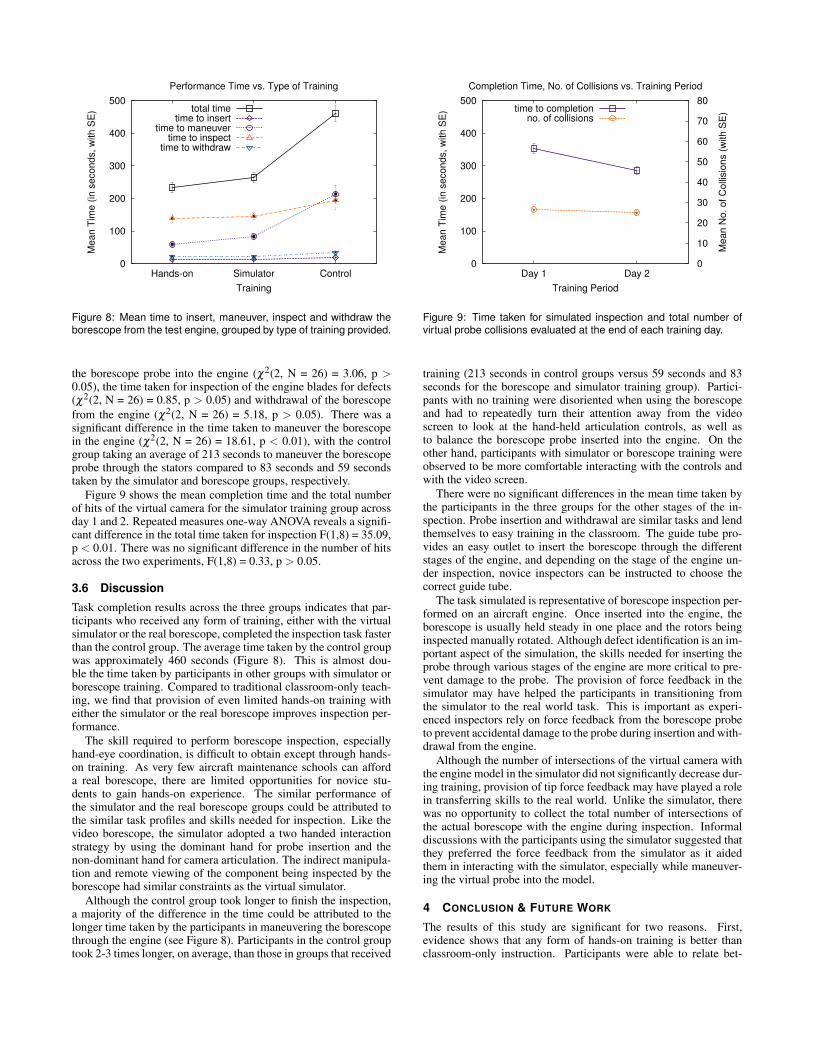
It was hypothesized that due to longer training, total inspectiontime and number of intersections with the engine model would de-crease from day 1 to day 2.
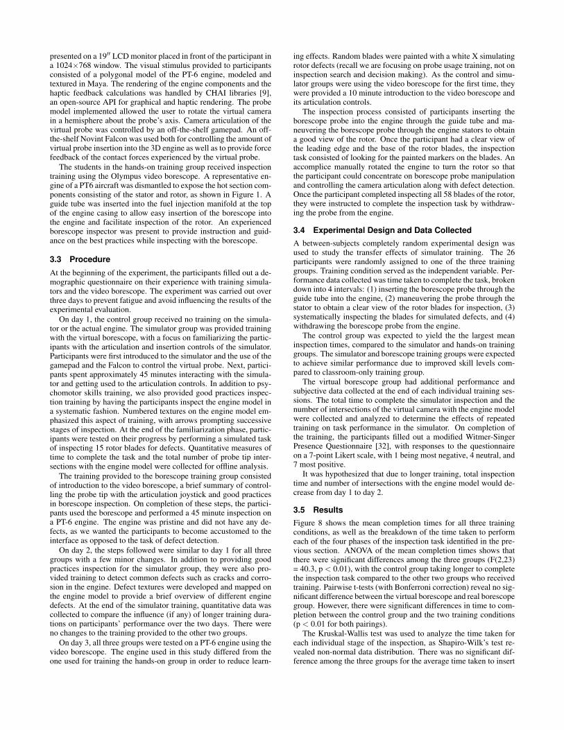
3.5 ResultsFigure 8 shows the mean completion times for all three trainingconditions, as well as the breakdown of the time taken to performeach of the four phases of the inspection task identified in the pre-vious section. ANOVA of the mean completion times shows thatthere were significant differences among the three groups (F(2,23)= 40.3, p < 0.01), with the control group taking longer to completethe inspection task compared to the other two groups who receivedtraining. Pairwise t-tests (with Bonferroni correction) reveal no sig-nificant difference between the virtual borescope and real borescopegroup. However, there were significant differences in time to com-pletion between the control group and the two training conditions(p < 0.01 for both pairings).
The Kruskal-Wallis test was used to analyze the time taken foreach individual stage of the inspection, as Shapiro-Wilk’s test re-vealed non-normal data distribution. There was no significant dif-ference among the three groups for the average time taken to insert
0
100
200
300
400
500
Hands-on Simulator Control
Me
an
Tim
e (
in s
eco
nd
s,
with
SE
)
Training
Performance Time vs. Type of Training
total timetime to insert
time to maneuvertime to inspect
time to withdraw
Figure 8: Mean time to insert, maneuver, inspect and withdraw theborescope from the test engine, grouped by type of training provided.
the borescope probe into the engine (χ2(2, N = 26) = 3.06, p >0.05), the time taken for inspection of the engine blades for defects(χ2(2, N = 26) = 0.85, p > 0.05) and withdrawal of the borescopefrom the engine (χ2(2, N = 26) = 5.18, p > 0.05). There was asignificant difference in the time taken to maneuver the borescopein the engine (χ2(2, N = 26) = 18.61, p < 0.01), with the controlgroup taking an average of 213 seconds to maneuver the borescopeprobe through the stators compared to 83 seconds and 59 secondstaken by the simulator and borescope groups, respectively.
Figure 9 shows the mean completion time and the total numberof hits of the virtual camera for the simulator training group acrossday 1 and 2. Repeated measures one-way ANOVA reveals a signifi-cant difference in the total time taken for inspection F(1,8) = 35.09,p < 0.01. There was no significant difference in the number of hitsacross the two experiments, F(1,8) = 0.33, p > 0.05.
3.6 Discussion
Task completion results across the three groups indicates that par-ticipants who received any form of training, either with the virtualsimulator or the real borescope, completed the inspection task fasterthan the control group. The average time taken by the control groupwas approximately 460 seconds (Figure 8). This is almost dou-ble the time taken by participants in other groups with simulator orborescope training. Compared to traditional classroom-only teach-ing, we find that provision of even limited hands-on training witheither the simulator or the real borescope improves inspection per-formance.
The skill required to perform borescope inspection, especiallyhand-eye coordination, is difficult to obtain except through hands-on training. As very few aircraft maintenance schools can afforda real borescope, there are limited opportunities for novice stu-dents to gain hands-on experience. The similar performance ofthe simulator and the real borescope groups could be attributed tothe similar task profiles and skills needed for inspection. Like thevideo borescope, the simulator adopted a two handed interactionstrategy by using the dominant hand for probe insertion and thenon-dominant hand for camera articulation. The indirect manipula-tion and remote viewing of the component being inspected by theborescope had similar constraints as the virtual simulator.
Although the control group took longer to finish the inspection,a majority of the difference in the time could be attributed to thelonger time taken by the participants in maneuvering the borescopethrough the engine (see Figure 8). Participants in the control grouptook 2-3 times longer, on average, than those in groups that received
0
100
200
300
400
500
Day 1 Day 2 0
10
20
30
40
50
60
70
80
Me
an
Tim
e (
in s
eco
nd
s,
with
SE
)
Me
an
No
. o
f C
olli
sio
ns (
with
SE
)
Training Period
Completion Time, No. of Collisions vs. Training Period
time to completionno. of collisions
Figure 9: Time taken for simulated inspection and total number ofvirtual probe collisions evaluated at the end of each training day.
training (213 seconds in control groups versus 59 seconds and 83seconds for the borescope and simulator training group). Partici-pants with no training were disoriented when using the borescopeand had to repeatedly turn their attention away from the videoscreen to look at the hand-held articulation controls, as well asto balance the borescope probe inserted into the engine. On theother hand, participants with simulator or borescope training wereobserved to be more comfortable interacting with the controls andwith the video screen.
There were no significant differences in the mean time taken bythe participants in the three groups for the other stages of the in-spection. Probe insertion and withdrawal are similar tasks and lendthemselves to easy training in the classroom. The guide tube pro-vides an easy outlet to insert the borescope through the differentstages of the engine, and depending on the stage of the engine un-der inspection, novice inspectors can be instructed to choose thecorrect guide tube.
The task simulated is representative of borescope inspection per-formed on an aircraft engine. Once inserted into the engine, theborescope is usually held steady in one place and the rotors beinginspected manually rotated. Although defect identification is an im-portant aspect of the simulation, the skills needed for inserting theprobe through various stages of the engine are more critical to pre-vent damage to the probe. The provision of force feedback in thesimulator may have helped the participants in transitioning fromthe simulator to the real world task. This is important as experi-enced inspectors rely on force feedback from the borescope probeto prevent accidental damage to the probe during insertion and with-drawal from the engine.
Although the number of intersections of the virtual camera withthe engine model in the simulator did not significantly decrease dur-ing training, provision of tip force feedback may have played a rolein transferring skills to the real world. Unlike the simulator, therewas no opportunity to collect the total number of intersections ofthe actual borescope with the engine during inspection. Informaldiscussions with the participants using the simulator suggested thatthey preferred the force feedback from the simulator as it aidedthem in interacting with the simulator, especially while maneuver-ing the virtual probe into the model.
4 CONCLUSION & FUTURE WORK
The results of this study are significant for two reasons. First,evidence shows that any form of hands-on training is better thanclassroom-only instruction. Participants were able to relate bet-
ter to inspection procedures through training with either the realborescope or the virtual simulator. Second, and more importantly,results suggest that the skills needed to manipulate the borescopeprobe that are obtained through on-the-job training may be acquiredby novice aircraft maintenance inspectors through simulator train-ing. Similar to pilots gaining flight experience through simulatortraining, the virtual borescope could be useful in improving studentoutcomes at aviation maintenance schools. Given the costs associ-ated with obtaining different engines and borescopes for inspectiontraining, virtual simulators integrated with classroom learning maybe useful for acquiring sufficient inspection competency for a fastertransition to the aviation maintenance workforce.
Simulator training outcomes can be improved in a number ofways. Unlike real inspection, we conducted the evaluation of sim-ulator training by focusing on only the probe manipulation skillsneeded during the inspection. The engine used for testing the par-ticipants was free from defects such as stress cracks, corrosion, andrust. The focus of a future study could be expanded to detect andidentify defects (search and decision tasks) by continuing trainingwith the simulator and comparing performance in the workforce.
ACKNOWLEDGEMENTS
We thank the volunteers at Greenville Tech Aircraft MaintenanceSchool for their participation. This work was partially funded byNational Science Foundation ATE grant #0703061.
REFERENCES
[1] T. Alderliesten, M. K. Konings, and W. J. Niessen. Simulation of min-imally invasive vascular interventions for training purposes. ComputerAided Surgery, 9:3–15, 2004.
[2] M. W. Allgaier and S. Ness, editors. Visual and Optical Testing.Number 8 in Nondestructive Testing Handbook. American Society forNondestructive Testing, Columbus, OH, 1993.
[3] L. M. Auer, D. Auer, and J. F. Knoplioch. Virtual Endoscopy forPlanning and Simulation of Minimally Invasive Neurosurgery. Lec-ture Notes in Computer Science, 1205:315–318, 1997.
[4] F. Barbagli, D. Prattichizzo, and K. Salisbury. Multi-point Interactionwith Real and Virtual Objects (Springer Tracts in Advanced Robotics).Springer-Verlag New York, Inc., Secaucus, NJ, USA, 2005.
[5] N. Becherer, J. Hesser, U. Kornmesser, D. Schranz, and R. Manner.Interactive physical simulation of catheter motion within major ves-sel structures and cavities for asd/vsd treatment. volume 6509, page65090U. SPIE, 2007.
[6] S. Bobo and C. Puckett. Visual Inspection for Aircraft, Draft AdvisoryCircular AC-43-XX. Federal Aviation Administration, 1995.
[7] S. N. Bobo. Visual inspection as an organized procedure. Nondestruc-tive Evaluation of Aging Aircraft, Airports, Aerospace Hardware, andMaterials, 2455(1):164–172, 1995.
[8] J. Brown, J.-C. Latombe, and K. Montgomery. Real-time knot-tyingsimulation. The Visual Computer: International Journal of ComputerGraphics, 20(2):165–179, 2004.
[9] F. Conti, F. Barbagli, R. Balaniuk, M. Halq, C. Lu, and D. Morris. TheCHAI Libraries. In Eurohaptics ’03, pages 496–500, 2003.
[10] F. Conti, O. Khatib, and C. Baur. Interactive Rendering Of De-formable Objects based on a Filling Sphere Modeling Approach. InIEEE International Conference on Robotics and Automation, vol-ume 3, pages 3716–3721, 2003.
[11] S. Cotin, C. Duriez, J. Lenoir, P. Neumann, and S. Dawson. Newapproaches to catheter navigation for interventional radiology simula-tion. In Proceedings of medical image computing and computer as-sisted intervention (MICCAI), pages 300–308, 2005.
[12] S. L. Dawson, S. Cotin, D. Meglan, D. W. Shaffer, and M. A. Fer-rell. Designing a computer-based simulator for interventional car-diology training. Catheterization and Cardiovascular Interventions,51(4):522–527, 2000.
[13] A. Ferlitsch, P. Glauninger, A. Gupper, M. Schillinger, M. Haefner,A. Gangl, and R. Schoefl. Evaluation of a Virtual Endoscopy
Simulator for Training of Gastrointestinal Endoscopy. Endoscopy,34(9):698–702, 2002.
[14] A. Ferlitsch, P. Glauninger, A. Gupper, M. Schillinger, M. Haefner,A. Gangl, and R. Schoefl. Virtual endoscopy simulation for trainingof gastrointestinal endoscopy. Endoscopy, 34(9):698–702, 2002.
[15] J. A. Ferwerda. Three Varieties of Realism in Computer Graphics. InHuman Vision and Electronic Imaging, pages 290–297, Bellingham,WA, 2003. SPIE.
[16] G. M. Fried, L. S. Feldman, M. C. Vassiliou, S. A. Fraser, D. Stan-bridge, G. Ghitulescu, and A. C. G. Proving the value of simulationin laparoscopic surgery. Annals of Surgery, 240(3):518–528, 2004.
[17] M. A. Guadagnoli and T. D. Lee. Challenge Point: A Framework forConceptualizing the Effects of Various Practice Conditions in MogorLearning. Journal of Motor Behavior, 36(2):212–224, 2004.
[18] B. Kubiak, N. Pietroni, F. Ganovelli, and M. Fratarcangeli. A robustmethod for real-time thread simulation. In VRST ’07: Proceedings ofthe 2007 ACM symposium on Virtual reality software and technology,pages 85–88, New York, NY, USA, 2007. ACM.
[19] P. Lamata, E. J. Gomez, F. Bello, R. L. Kneebone, R. Aggarwal, andF. Lamata. Conceptual framework for laparoscopic vr simulators.IEEE Computer Graphics and Applications, 26(6):69–79, 2006.
[20] S. Laycock and A. Day. Recent developments and applications ofhaptic devices. Computer Graphics Forum, 22(2):117–132, 2003.
[21] S. D. Laycock and A. M. Day. Incorporating haptic feedback forthe simulation of a deformable tool in a rigid scene. Computers andGraphics, 29(3):341–351, 2005.
[22] J. Lenoir, S. Cotin, C. Duriez, and P. Neumann. Interactive physically-based simulation of catheter and guidewire. Computers and Graphics,30(3):416–422, 2006.
[23] S. Loncaric, T. Markovinovic, T. Petrovic, D. Ramljak, and E. So-rantin. Construction of Virtual Environment for Endoscopy. In Pro-ceedings of the IEEE International Conference on Multimedia Com-puting and Systems, 1999.
[24] W. Nowinski and C.-K. Chui. Simulation of interventional neuroradi-ology procedures. Proceedings of International Workshop on MedicalImaging and Augmented Reality, pages 87–94, 2001.
[25] D. K. Pai. Strands: Interactive simulation of thin solids using cosseratmodels. Computer Graphics Forum, 21(3):347–352, 2002.
[26] D. C. Ruspini, K. Kolarov, and O. Khatib. The haptic display ofcomplex graphical environments. In SIGGRAPH ’97: Proceedingsof the 24th annual conference on Computer graphics and interac-tive techniques, pages 345–352, New York, NY, USA, 1997. ACMPress/Addison-Wesley Publishing Co.
[27] G. Saupin, C. Duriez, and S. Cotin. Contact model for haptic medicalsimulations. 5104:157–165, 2008.
[28] N. E. Seymour, A. G. Gallagher, S. A. Roman, M. K. O’Brien, V. K.Bansal, D. K. Andersen, and R. M. Satava. Virtual Reality TrainingImproves Operating Room Performance: Results of a Randomized,Double-Blinded Study. Annals of Surgery, 236(4):458–464, 2002.
[29] D. Vembar, A. T. Duchowski, A. K. Gramopadhye, and C. Washburn.Improving Simulated Borescope Inspection with Constrained CameraMotion and Haptic Feedback. In Proceedings of Graphics Interface,2009.
[30] F. Wang, E. Burdet, A. Dhanik, T. Poston, and C. L. Teo. Dynamicthread for real-time knot-tying. In WHC ’05: Proceedings of the FirstJoint Eurohaptics Conference and Symposium on Haptic Interfacesfor Virtual Environment and Teleoperator Systems, pages 507–508,Washington, DC, USA, 2005. IEEE Computer Society.
[31] F. Wang, L. Duratti, E. Samur, U. Spaelter, and H. Bleuler. AComputer-Based Real-Time Simulation of Interventional Radiology.In 29th Annual International Conference of the IEEE Engineering inMedicine and Biology Society (IEEE-EMBS), 2007.
[32] B. G. Witmer and M. J. Singer. Measuring Presence in Virtual Envi-ronments: A Presence Questionnaire. Presence, 7(3):225–240, 1998.
[33] C. Zilles and J. Salisbury. A constraint-based god-object method forhaptic display. Proceedings. 1995 IEEE/RSJ International Conferenceon Intelligent Robots and Systems 95, ’Human Robot Interaction andCooperative Robots’, 3:146–151, Aug 1995.