Embed Size (px)
Citation preview
VIV and galloping instability of a rectangular cylinder with a side ratio of 1.5Claudio Mannini1, Antonino M. Marra1, Gianni Bartoli1
1CRIACIV/Department of Civil and Environmental Engineering, University of Florence, Via S. Marta 3, 50139 Florence, Italyemail: [email protected], [email protected], [email protected]
ABSTRACT: The interaction between galloping and vortex-induced vibration was experimentally investigated in the particular caseof an infinitely long rectangular cylinder with a side ratio of 1.5 in smooth flow. This geometry was found to be very unstable andlarge oscillations were observed also at high Scruton number in a range where no excitation was expected according to the classicaltheory. A ratio of the quasi-steady galloping critical wind speed to Karman-vortex resonance velocity larger than a minimum valuein the range 7 ÷ 9 seems to be necessary in order to avoid such a combined instability. This result, which finds a support from theliterature, is in strong disagreement with Eurocode 1, which unconservatively claims that interaction can be excluded for a ratio ofcritical velocities outside the range 0.7÷1.5. The effect of Reynolds number was also partially investigated by testing two sectionmodels at different scales. Finally, the experiments highlighted several nonlinear features of the dynamic system, such as secondaryand superharmonic resonances, hysteresis and frequency demultiplication.
KEY WORDS: Galloping; Vortex-induced vibration; Aeroelastic interaction; Rectangular cylinder; Wind-tunnel tests.
1 INTRODUCTION
Galloping is a dynamic instability of slender prismatic structurescaused by the self-excitation due to wind. Mathematicallyspeaking it is a supercritical Hopf bifurcation and then, oncethe critical wind speed has been exceeded, it manifests itselfas a limit-cycle nearly-harmonic oscillation whose amplitudesteadily grows by increasing the flow velocity. The criticalwind speed is usually calculated through the quasi-steady forcecriterion [1]. It is proportional to a mass-damping parametercalled Scruton number and inversely proportional to a stabilityparameter obtained by measurements on the stationary body.
Vortex-induced vibration is caused by the nonlinear reso-nance of the force due to the alternate shedding of vortices withone mode of vibration of the structure and self-excitation is akey issue in case of large-amplitude oscillations. The excitationstarts at a critical wind speed which depends on the Strouhalnumber and disappears beyond a certain flow velocity. Theamplitude of vibration and the extension of the so-called “lock-in” range depend on the mass ratio and structural damping,combined as Scruton number for conventional structures inairflow.
In slender prismatic structures with bluff cross section andsufficient afterbody both phenomena are possible and thereforeinteraction can occur. In particular, this is true for rectangularcylinders in smooth flow with 0.6 . B/D . 2.8, being B thewidth and D the depth of the section, which are known to bevery unstable with respect to galloping [2]. Eurocode 1 [3] statesthat, if the ratio of the galloping to the VIV critical wind speed(the former calculated with the classical quasi-steady theory) iseither lower than 0.7 or larger than 1.5 the two phenomena canbe considered separately. Nevertheless, beside the data reportedin the present work, in the literature there are many experimentalresults that clearly disagree with this statement, as clearly shownby the extensive review reported in [4]. Therein, the difficulties
in the prediction of the critical wind speed are also highlighted.In particular, by collecting literature data from measurementsof the galloping stability parameters, a large uncertainty in itsestimation was observed due to the strong dependence of itsvalue on the test conditions (quality of model edges, Reynoldsnumber, blockage ratio, characteristics of the oncoming flow,etc). However, the non-conservativeness of the values suggestedby Eurocode 1 [3] is apparent.
It was shown that prismatic towers with rectangular crosssection could also be prone to galloping [5], [6], [7] and this maybe of particular concern nowadays due to the reduction of modalfrequencies and damping, as well as the increased lightness andslenderness of modern tall buildings [4]. A possible interactionbetween VIV and galloping makes the problem even hardersince it allows the onset of limit-cycle oscillations at relativelylow wind speed, that is at the critical velocity for VIV, butwith amplitudes unrestrictedly growing with the flow speed, astypical of galloping, even for large values of the Scruton number.
In this work the aeroelastic behaviour of a sharp-edgedrectangular 3:2 cylinder (B/D = 1.5) with the short sideD perpendicular to the flow was experimentally investigatedthrough static and aeroelastic tests in order to shed some lighton the complicated VIV-galloping interaction phenomenon. Infact, this geometry has not been as extensively studied as thesquare cylinder but interestingly it appears to be even moresusceptible to this combined instability. Two sectional models atdifferent scales were tested by using a static and an aeroelasticrig, in order to investigate two Reynolds number ranges and tospan a large interval of Scruton numbers. Force measurements,velocity-amplitude diagrams and flow-velocity fluctuations inthe wake of the oscillating body are discussed to provide moreinsight into the phenomenon. Particular attention is devoted tononlinear features of the dynamic system, such as secondary andsuperharmonic resonances, hysteresis patterns and frequencydemultiplication.
Proceedings of the 9th International Conference on Structural Dynamics, EURODYN 2014Porto, Portugal, 30 June - 2 July 2014
A. Cunha, E. Caetano, P. Ribeiro, G. Müller (eds.)ISSN: 2311-9020; ISBN: 978-972-752-165-4
3121
(a) (b)
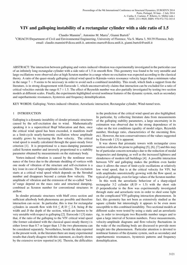
Figure 1. View of wooden model (D = 77 mm) (a) and aluminum model (D = 30 mm) (b) mounted on the aeroelastic rig.
2 WIND TUNNEL TESTS
Experiments were conducted in the open-circuit boundary layerwind tunnel of CRIACIV, located in Prato, Italy. The test sectionis 2.42 m wide and 1.60 m high. First, a wooden sectional model(Figures 1(a) and 2), 986 mm long, 116 mm wide (B) and 77 mmdeep (D), was used to perform both static and dynamic tests.To enforce bidimensional flow conditions, rectangular plates inplywood were provided at the model ends; their dimensions(450 mm × 150 mm × 4 mm) were defined according to ESDUprescriptions [8], [9]. The mass of the model, end-plates andsupporting carbon-fiber tube was 1.730 kg. The model was alsoequipped with pressure taps located at the center of each side ofthe rectangle; registrations at a sampling frequency of 500 Hzwere performed with piezoelectric pressure transducers and thesystem PSI DTC Initium.
Afterwards, the tests were repeated on an aluminum model(Figure 1(b)), 1 m long, 45 mm wide and 30 mm deep.Rectangular end plates in steel (150 mm × 90 mm × 2 mm,the long side extending 15 mm upstream the downward faceand 90 mm downstream the leeward face) were provided andthe total mass of the model was 2.672 kg.
Both models were placed horizontally in the wind tunnel withthe shorter side of the section perpendicular to the flow. Theblockage ratio given by the model alone, calculated as D/Hwt ,being Hwt the height of the wind-tunnel section, was 4.8% forthe wooden model and 1.9% for the aluminum model. All thetests were carried out in smooth flow with a turbulence intensityof about 1%.
For measurements of velocity fluctuations in the wake asingle hot-wire anemometer, connected to a Dantec CTA Bridge56C01, was placed in several positions behind the models.
2.1 Static set-up
Most of the static tests were performed on the largest woodenmodel. It was connected to six load cells (three on each side)through a system of connecting rods with spherical hinges,which allowed the measurement of drag, lift and moment. The
Figure 2. Sketch of the wooden model with end-plates.
model was placed inside a rig consisting of two large plexiglasswalls supported by two metallic frames connected both to thefloor and the ceiling of the wind tunnel. The load cells werefixed to these frames. The aerodynamic force coefficients weredetermined for angles of attack ranging approximately from−10o to +10o.
As for the aluminum model, in one case the aeroelastic rig(see Section 2.2) was blocked with pretensioned cables and thevelocity fluctuation in the wake were measured with a hot-wireanemometer.
2.2 Aeroelastatic set-up
Figure 1 shows the aeroelastic set-up. The model wasconnected to two shear-type steel frames allowing only a verticaldisplacement due to the very large in-plane flexural stiffnessof the vertical elements. The aerodynamic damping due to theexposition to the flow of the plate-springs was verified to be verysmall. The stiffness of the suspension system was modified inthe different tests by varying the length of the plate-springs.
The displacements of the model were recorded respectivelywith two non-contact laser transducers. The damping andfrequency of the system were measured imposing several times
Proceedings of the 9th International Conference on Structural Dynamics, EURODYN 2014
3122
0 0.1 0.2 0.3 0.4 0.510
−4
10−2
100
102
104 Re = 61200
nD/U
SLL
nD/U = 0.106 nD/U = 0.318
n0D/U
(a)
0 0.1 0.2 0.3 0.4 0.510
−4
10−2
100
102
104 Re = 96600
nD/U
SLL
nD/U = 0.106
nD/U = 0.212
nD/U = 0.318
n0D/U
(b)
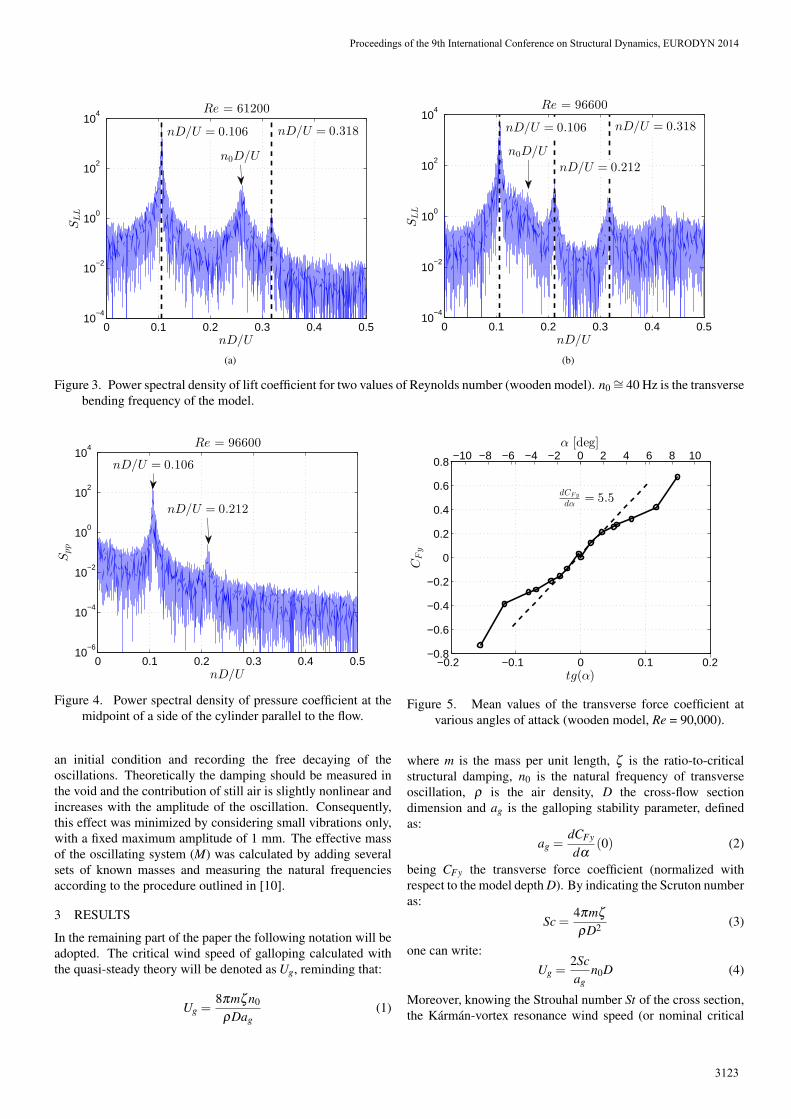
Figure 3. Power spectral density of lift coefficient for two values of Reynolds number (wooden model). n0 ∼= 40 Hz is the transversebending frequency of the model.
0 0.1 0.2 0.3 0.4 0.510
−6
10−4
10−2
100
102
104 Re = 96600
nD/U
Spp
nD/U = 0.212
nD/U = 0.106
Figure 4. Power spectral density of pressure coefficient at themidpoint of a side of the cylinder parallel to the flow.
an initial condition and recording the free decaying of theoscillations. Theoretically the damping should be measured inthe void and the contribution of still air is slightly nonlinear andincreases with the amplitude of the oscillation. Consequently,this effect was minimized by considering small vibrations only,with a fixed maximum amplitude of 1 mm. The effective massof the oscillating system (M) was calculated by adding severalsets of known masses and measuring the natural frequenciesaccording to the procedure outlined in [10].
3 RESULTS
In the remaining part of the paper the following notation will beadopted. The critical wind speed of galloping calculated withthe quasi-steady theory will be denoted as Ug, reminding that:
Ug =8πmζ n0
ρDag(1)
−0.2 −0.1 0 0.1 0.2−0.8
−0.6
−0.4
−0.2
0
0.2
0.4
0.6
0.8
dCFy
dα= 5.5
tg(α)
CFy
−10 −8 −6 −4 −2 0 2 4 6 8 10α [deg]
Figure 5. Mean values of the transverse force coefficient atvarious angles of attack (wooden model, Re = 90,000).
where m is the mass per unit length, ζ is the ratio-to-criticalstructural damping, n0 is the natural frequency of transverseoscillation, ρ is the air density, D the cross-flow sectiondimension and ag is the galloping stability parameter, definedas:
ag =dCFy
dα(0) (2)
being CFy the transverse force coefficient (normalized withrespect to the model depth D). By indicating the Scruton numberas:
Sc =4πmζρD2 (3)
one can write:Ug =
2Scag
n0D (4)
Moreover, knowing the Strouhal number St of the cross section,the Karman-vortex resonance wind speed (or nominal critical
Proceedings of the 9th International Conference on Structural Dynamics, EURODYN 2014
3123
0 0.05 0.1 0.15 0.2 0.25 0.3 0.35 0.410
−1
100
101
102
103
104
nD/U
Suu/u′2[s]
Re = 5200
(a)
0 0.05 0.1 0.15 0.2 0.25 0.3 0.35 0.410
−1
100
101
102
103
104
nD/U
Suu/u′2[s]
Re = 44000
(b)
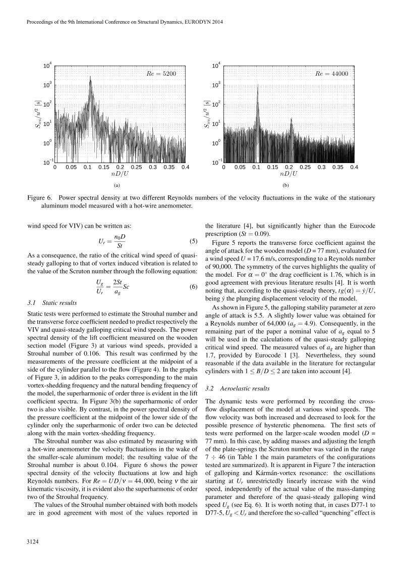
Figure 6. Power spectral density at two different Reynolds numbers of the velocity fluctuations in the wake of the stationaryaluminum model measured with a hot-wire anemometer.
wind speed for VIV) can be written as:
Ur =n0DSt
(5)
As a consequence, the ratio of the critical wind speed of quasi-steady galloping to that of vortex induced vibration is related tothe value of the Scruton number through the following equation:
Ug
Ur=
2Stag
Sc (6)
3.1 Static results
Static tests were performed to estimate the Strouhal number andthe transverse force coefficient needed to predict respectively theVIV and quasi-steady galloping critical wind speeds. The powerspectral density of the lift coefficient measured on the woodensection model (Figure 3) at various wind speeds, provided aStrouhal number of 0.106. This result was confirmed by themeasurements of the pressure coefficient at the midpoint of aside of the cylinder parallel to the flow (Figure 4). In the graphsof Figure 3, in addition to the peaks corresponding to the mainvortex-shedding frequency and the natural bending frequency ofthe model, the superharmonic of order three is evident in the liftcoefficient spectra. In Figure 3(b) the superharmonic of ordertwo is also visible. By contrast, in the power spectral density ofthe pressure coefficient at the midpoint of the lower side of thecylinder only the superharmonic of order two can be detectedalong with the main vortex-shedding frequency.
The Strouhal number was also estimated by measuring witha hot-wire anemometer the velocity fluctuations in the wake ofthe smaller-scale aluminum model; the resulting value of theStrouhal number is about 0.104. Figure 6 shows the powerspectral density of the velocity fluctuations at low and highReynolds numbers. For Re = UD/ν = 44,000, being ν the airkinematic viscosity, it is evident also the superharmonic of ordertwo of the Strouhal frequency.
The values of the Strouhal number obtained with both modelsare in good agreement with most of the values reported in
the literature [4], but significantly higher than the Eurocodeprescription (St = 0.09).
Figure 5 reports the transverse force coefficient against theangle of attack for the wooden model (D = 77 mm), evaluated fora wind speed U = 17.6 m/s, corresponding to a Reynolds numberof 90,000. The symmetry of the curves highlights the quality ofthe model. For α = 0◦ the drag coefficient is 1.76, which is ingood agreement with previous literature results [4]. It is worthnoting that, according to the quasi-steady theory, tg(α) = y/U ,being y the plunging displacement velocity of the model.
As shown in Figure 5, the galloping stability parameter at zeroangle of attack is 5.5. A slightly lower value was obtained fora Reynolds number of 64,000 (ag = 4.9). Consequently, in theremaining part of the paper a nominal value of ag equal to 5will be used in the calculations of the quasi-steady gallopingcritical wind speed. The measured values of ag are higher than1.7, provided by Eurocode 1 [3]. Nevertheless, they soundreasonable if the data available in the literature for rectangularcylinders with 1 ≤ B/D ≤ 2 are taken into account [4].
3.2 Aeroelastic results
The dynamic tests were performed by recording the cross-flow displacement of the model at various wind speeds. Theflow velocity was both increased and decreased to look for thepossible presence of hysteretic phenomena. The first sets oftests were performed on the larger-scale wooden model (D =77 mm). In this case, by adding masses and adjusting the lengthof the plate-springs the Scruton number was varied in the range7 ÷ 46 (in Table 1 the main parameters of the configurationstested are summarized). It is apparent in Figure 7 the interactionof galloping and Karman-vortex resonance: the oscillationsstarting at Ur unrestrictedly linearly increase with the windspeed, independently of the actual value of the mass-dampingparameter and therefore of the quasi-steady galloping windspeed Ug (see Eq. 6). It is worth noting that, in cases D77-1 toD77-5, Ug <Ur and therefore the so-called “quenching” effect is
Proceedings of the 9th International Conference on Structural Dynamics, EURODYN 2014
3124
0 0.25 0.5 0.75 1 1.25 1.5 1.750
0.02
0.04
0.06
0.08
0.1
0.12
0.14
0.16
U/Ur
y′/D
1
0.233
D77−1 (Sc = 7)D77−2 (Sc = 8)D77−5 (Sc = 16)D77−6 (Sc = 28)D77−7 (Sc = 46)
0 2 4 6 8 10 12 14 16U/n0D
(a)
0.3 0.4 0.5 0.60
0.01
0.02
0.03
0.04
0.05
0.06
U/Ur
y′/D
1
0.259
10.197
C
A
B
D77−2 (Sc = 8)D77−4 (Sc = 12)D77−5 (Sc = 16)
2 3 4 5 6U/n0D
(b)
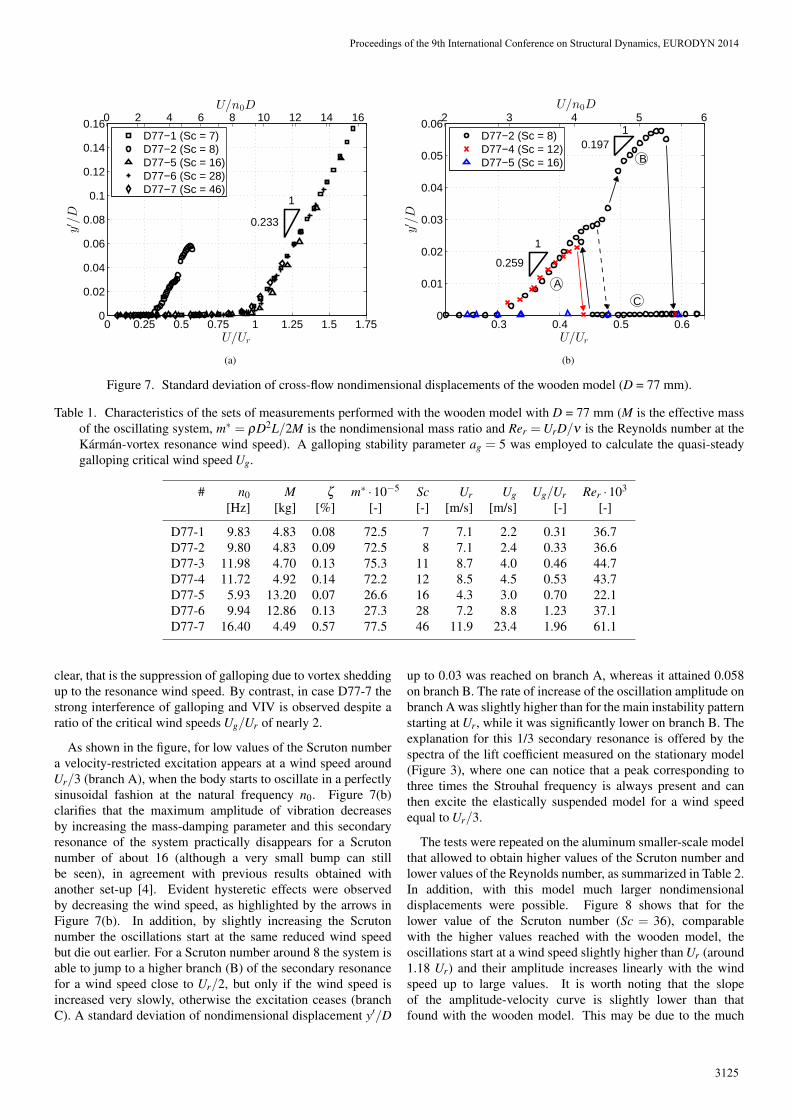
Figure 7. Standard deviation of cross-flow nondimensional displacements of the wooden model (D = 77 mm).
Table 1. Characteristics of the sets of measurements performed with the wooden model with D = 77 mm (M is the effective massof the oscillating system, m∗ = ρD2L/2M is the nondimensional mass ratio and Rer =UrD/ν is the Reynolds number at theKarman-vortex resonance wind speed). A galloping stability parameter ag = 5 was employed to calculate the quasi-steadygalloping critical wind speed Ug.
# n0 M ζ m∗ ·10−5 Sc Ur Ug Ug/Ur Rer ·103
[Hz] [kg] [%] [-] [-] [m/s] [m/s] [-] [-]
D77-1 9.83 4.83 0.08 72.5 7 7.1 2.2 0.31 36.7D77-2 9.80 4.83 0.09 72.5 8 7.1 2.4 0.33 36.6D77-3 11.98 4.70 0.13 75.3 11 8.7 4.0 0.46 44.7D77-4 11.72 4.92 0.14 72.2 12 8.5 4.5 0.53 43.7D77-5 5.93 13.20 0.07 26.6 16 4.3 3.0 0.70 22.1D77-6 9.94 12.86 0.13 27.3 28 7.2 8.8 1.23 37.1D77-7 16.40 4.49 0.57 77.5 46 11.9 23.4 1.96 61.1
clear, that is the suppression of galloping due to vortex sheddingup to the resonance wind speed. By contrast, in case D77-7 thestrong interference of galloping and VIV is observed despite aratio of the critical wind speeds Ug/Ur of nearly 2.
As shown in the figure, for low values of the Scruton numbera velocity-restricted excitation appears at a wind speed aroundUr/3 (branch A), when the body starts to oscillate in a perfectlysinusoidal fashion at the natural frequency n0. Figure 7(b)clarifies that the maximum amplitude of vibration decreasesby increasing the mass-damping parameter and this secondaryresonance of the system practically disappears for a Scrutonnumber of about 16 (although a very small bump can stillbe seen), in agreement with previous results obtained withanother set-up [4]. Evident hysteretic effects were observedby decreasing the wind speed, as highlighted by the arrows inFigure 7(b). In addition, by slightly increasing the Scrutonnumber the oscillations start at the same reduced wind speedbut die out earlier. For a Scruton number around 8 the system isable to jump to a higher branch (B) of the secondary resonancefor a wind speed close to Ur/2, but only if the wind speed isincreased very slowly, otherwise the excitation ceases (branchC). A standard deviation of nondimensional displacement y′/D
up to 0.03 was reached on branch A, whereas it attained 0.058on branch B. The rate of increase of the oscillation amplitude onbranch A was slightly higher than for the main instability patternstarting at Ur, while it was significantly lower on branch B. Theexplanation for this 1/3 secondary resonance is offered by thespectra of the lift coefficient measured on the stationary model(Figure 3), where one can notice that a peak corresponding tothree times the Strouhal frequency is always present and canthen excite the elastically suspended model for a wind speedequal to Ur/3.
The tests were repeated on the aluminum smaller-scale modelthat allowed to obtain higher values of the Scruton number andlower values of the Reynolds number, as summarized in Table 2.In addition, with this model much larger nondimensionaldisplacements were possible. Figure 8 shows that for thelower value of the Scruton number (Sc = 36), comparablewith the higher values reached with the wooden model, theoscillations start at a wind speed slightly higher than Ur (around1.18 Ur) and their amplitude increases linearly with the windspeed up to large values. It is worth noting that the slopeof the amplitude-velocity curve is slightly lower than thatfound with the wooden model. This may be due to the much
Proceedings of the 9th International Conference on Structural Dynamics, EURODYN 2014
3125
0 2 4 6 8 10 120
0.1
0.2
0.3
0.4
0.5
0.6
U/Ur
y′/D
0 20 40 60 80 100U/n0D
0.5 0.75 1 1.25 1.5 1.75 20
0.025
0.05
0.075
0.1
U/Ur
y′/D
1
0.151
1
0.174
D30−1 (Sc = 36)D30−2 (Sc = 93)D30−3 (Sc = 166)D30−4 (Sc = 216)D30−5 (Sc = 224)D30−6 (Sc = 123)D30−7 (Sc = 146)
5 10 15U/n0D
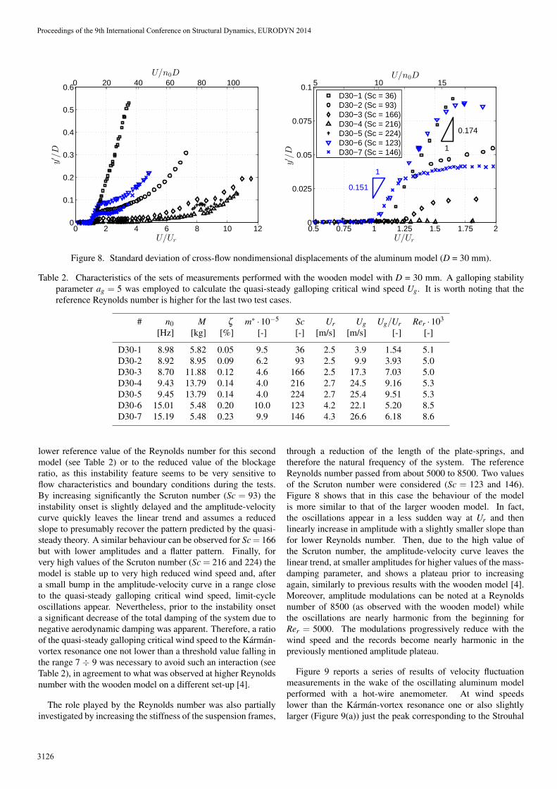
Figure 8. Standard deviation of cross-flow nondimensional displacements of the aluminum model (D = 30 mm).
Table 2. Characteristics of the sets of measurements performed with the wooden model with D = 30 mm. A galloping stabilityparameter ag = 5 was employed to calculate the quasi-steady galloping critical wind speed Ug. It is worth noting that thereference Reynolds number is higher for the last two test cases.
# n0 M ζ m∗ ·10−5 Sc Ur Ug Ug/Ur Rer ·103
[Hz] [kg] [%] [-] [-] [m/s] [m/s] [-] [-]
D30-1 8.98 5.82 0.05 9.5 36 2.5 3.9 1.54 5.1D30-2 8.92 8.95 0.09 6.2 93 2.5 9.9 3.93 5.0D30-3 8.70 11.88 0.12 4.6 166 2.5 17.3 7.03 5.0D30-4 9.43 13.79 0.14 4.0 216 2.7 24.5 9.16 5.3D30-5 9.45 13.79 0.14 4.0 224 2.7 25.4 9.51 5.3D30-6 15.01 5.48 0.20 10.0 123 4.2 22.1 5.20 8.5D30-7 15.19 5.48 0.23 9.9 146 4.3 26.6 6.18 8.6
lower reference value of the Reynolds number for this secondmodel (see Table 2) or to the reduced value of the blockageratio, as this instability feature seems to be very sensitive toflow characteristics and boundary conditions during the tests.By increasing significantly the Scruton number (Sc = 93) theinstability onset is slightly delayed and the amplitude-velocitycurve quickly leaves the linear trend and assumes a reducedslope to presumably recover the pattern predicted by the quasi-steady theory. A similar behaviour can be observed for Sc= 166but with lower amplitudes and a flatter pattern. Finally, forvery high values of the Scruton number (Sc = 216 and 224) themodel is stable up to very high reduced wind speed and, aftera small bump in the amplitude-velocity curve in a range closeto the quasi-steady galloping critical wind speed, limit-cycleoscillations appear. Nevertheless, prior to the instability onseta significant decrease of the total damping of the system due tonegative aerodynamic damping was apparent. Therefore, a ratioof the quasi-steady galloping critical wind speed to the Karman-vortex resonance one not lower than a threshold value falling inthe range 7 ÷ 9 was necessary to avoid such an interaction (seeTable 2), in agreement to what was observed at higher Reynoldsnumber with the wooden model on a different set-up [4].
The role played by the Reynolds number was also partiallyinvestigated by increasing the stiffness of the suspension frames,
through a reduction of the length of the plate-springs, andtherefore the natural frequency of the system. The referenceReynolds number passed from about 5000 to 8500. Two valuesof the Scruton number were considered (Sc = 123 and 146).Figure 8 shows that in this case the behaviour of the modelis more similar to that of the larger wooden model. In fact,the oscillations appear in a less sudden way at Ur and thenlinearly increase in amplitude with a slightly smaller slope thanfor lower Reynolds number. Then, due to the high value ofthe Scruton number, the amplitude-velocity curve leaves thelinear trend, at smaller amplitudes for higher values of the mass-damping parameter, and shows a plateau prior to increasingagain, similarly to previous results with the wooden model [4].Moreover, amplitude modulations can be noted at a Reynoldsnumber of 8500 (as observed with the wooden model) whilethe oscillations are nearly harmonic from the beginning forRer = 5000. The modulations progressively reduce with thewind speed and the records become nearly harmonic in thepreviously mentioned amplitude plateau.
Figure 9 reports a series of results of velocity fluctuationmeasurements in the wake of the oscillating aluminum modelperformed with a hot-wire anemometer. At wind speedslower than the Karman-vortex resonance one or also slightlylarger (Figure 9(a)) just the peak corresponding to the Strouhal
Proceedings of the 9th International Conference on Structural Dynamics, EURODYN 2014
3126
0 1 2 3 4 5 610
−1
100
101
102
103
104
n/n0
Suu/u′2[s]
U/Ur = 1.22
0 0.1 0.2 0.3 0.4 0.5nD/U
(a)
0 1 2 3 4 5 610
−1
100
101
102
103
104
n/n0
Suu/u′2[s]
U/Ur = 1.25
0 0.1 0.2 0.3 0.4nD/U
(b)
0 1 2 3 4 5 610
−1
100
101
102
103
104
n/n0
Suu/u′2[s]
U/Ur = 1.4
0 0.1 0.2 0.3 0.4nD/U
(c)
0 1 2 3 4 5 610
−1
100
101
102
103
104
n/n0
Suu/u′2[s]
U/Ur = 1.53
0 0.1 0.2 0.3 0.4nD/U
(d)
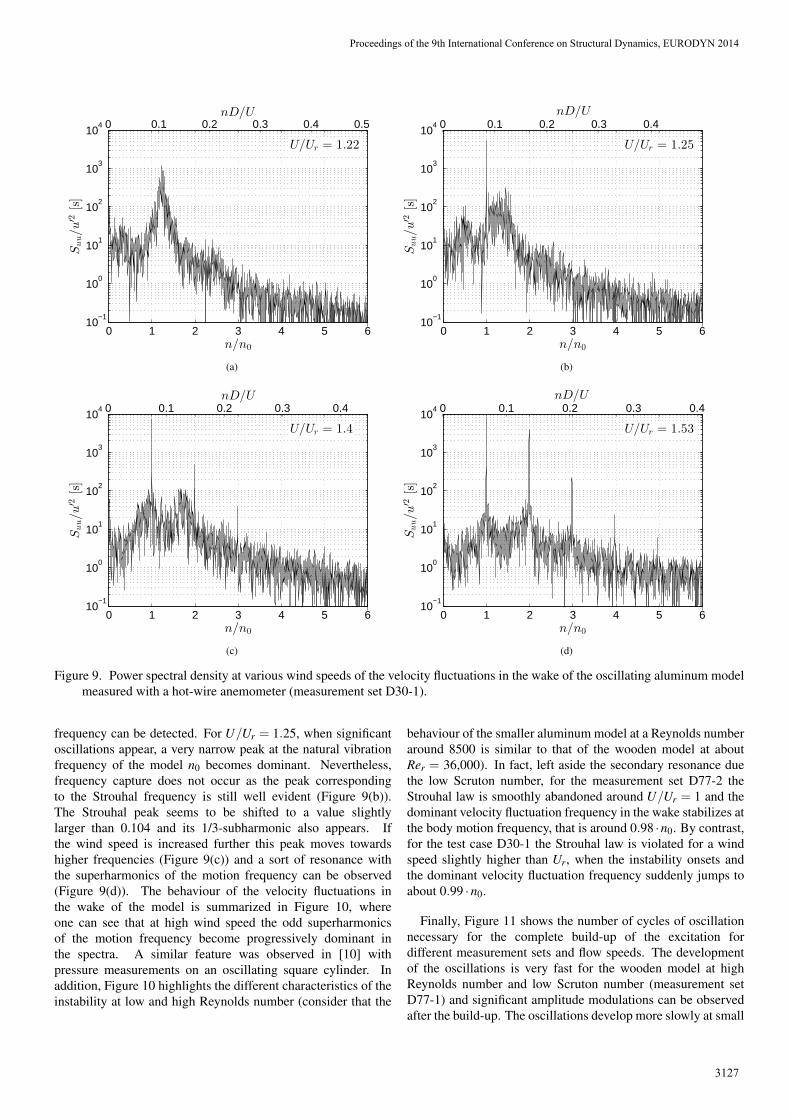
Figure 9. Power spectral density at various wind speeds of the velocity fluctuations in the wake of the oscillating aluminum modelmeasured with a hot-wire anemometer (measurement set D30-1).
frequency can be detected. For U/Ur = 1.25, when significantoscillations appear, a very narrow peak at the natural vibrationfrequency of the model n0 becomes dominant. Nevertheless,frequency capture does not occur as the peak correspondingto the Strouhal frequency is still well evident (Figure 9(b)).The Strouhal peak seems to be shifted to a value slightlylarger than 0.104 and its 1/3-subharmonic also appears. Ifthe wind speed is increased further this peak moves towardshigher frequencies (Figure 9(c)) and a sort of resonance withthe superharmonics of the motion frequency can be observed(Figure 9(d)). The behaviour of the velocity fluctuations inthe wake of the model is summarized in Figure 10, whereone can see that at high wind speed the odd superharmonicsof the motion frequency become progressively dominant inthe spectra. A similar feature was observed in [10] withpressure measurements on an oscillating square cylinder. Inaddition, Figure 10 highlights the different characteristics of theinstability at low and high Reynolds number (consider that the
behaviour of the smaller aluminum model at a Reynolds numberaround 8500 is similar to that of the wooden model at aboutRer = 36,000). In fact, left aside the secondary resonance duethe low Scruton number, for the measurement set D77-2 theStrouhal law is smoothly abandoned around U/Ur = 1 and thedominant velocity fluctuation frequency in the wake stabilizes atthe body motion frequency, that is around 0.98 ·n0. By contrast,for the test case D30-1 the Strouhal law is violated for a windspeed slightly higher than Ur, when the instability onsets andthe dominant velocity fluctuation frequency suddenly jumps toabout 0.99 ·n0.
Finally, Figure 11 shows the number of cycles of oscillationnecessary for the complete build-up of the excitation fordifferent measurement sets and flow speeds. The developmentof the oscillations is very fast for the wooden model at highReynolds number and low Scruton number (measurement setD77-1) and significant amplitude modulations can be observedafter the build-up. The oscillations develop more slowly at small
Proceedings of the 9th International Conference on Structural Dynamics, EURODYN 2014
3127

0 1 2 3 40
1
2
3
4
5
6
U/Ur
n/n0
D77−2D30−1
0 5 10 15 20 25 30 35U/n0D
Figure 10. Variation with the wind speed of the dominantfrequency of velocity fluctuation in the wake of theoscillating models measured with a hot-wire anemometer.
0 500 1000 1500 20000
0.05
0.1
0.15
0.2
0.25
0.3
0.35
0.4
n0t
y′/D
D77-1 - U/Ur = 1.47
D30-1 - U/Ur = 1.42
D30-1 - U/Ur = 1.89
D30-1 - U/Ur = 2.72
D30-6 - U/Ur = 1.15
D30-6 - U/Ur = 1.31
D30-6 - U/Ur = 1.39
D30-6 - U/Ur = 1.78
D30-6 - U/Ur = 2.14
Figure 11. Variation of the amplitude of oscillation duringbuild-up tests.
Reynolds number (measurement set D30-1) and, as previouslynoted, no amplitude modulation is evident. At higher Scrutonnumber (measurement set D30-6) the build-up requires evenmore cycles of oscillation and in the plateau of the amplitude-velocity curve (Figure 8) it is independent of the reducedvelocity. One can also remark that for this measurement set,at slightly higher Reynolds number, the displacement timehistories after build-up show again amplitude modulations priorto entering in the previously mentioned plateau.
4 CONCLUSIONS
The results of wind tunnel tests on a rectangular 3:2 cylinderdemonstrated the strong susceptibility of this cross section toa combined VIV-galloping instability. The effect of Reynoldsnumber was partially investigated by the use of two sectionmodels at different scales. It was observed that a ratiobetween the theoretical critical velocities for the two individual
phenomena not lower than a threshold value falling in therange 7 ÷ 9 was necessary to avoid such an interaction. Thiscondition corresponds to large values of the Scruton numberand from the practical engineering point of view it means thatstructures with not so small values of damping and mass may beprone to galloping-type oscillations in a range of wind speedswhere small-amplitude vortex-induced vibrations are expected.This dangerous scenario is not accounted for by Eurocode 1,which excludes the possibility of interaction between VIV andgalloping if the ratio of the two individual critical wind speedsis outside the range 0.7÷1.5.
Several nonlinear features of the fluid-structure coupledsystem were highlighted and one of the most remarkable issurely the excitation observed for low values of the Scrutonnumber in a wind speed range starting at one third of themain Karman-vortex resonance velocity. Results showed thatsignificant amplitudes of oscillation can be obtained and in somecases, as they can occur at very low wind speeds, such vibrationsshould be considered in the structural design, although generallynot accounted for by codes and standards.
Finally, measurements of velocity fluctuations in the wake ofthe oscillating models shed some light on the actual mechanismof excitation during the VIV-galloping instability. In particular,the role of vortex shedding and of the superharmonics of themotion frequency components was clarified.
ACKNOWLEDGMENTS
The Authors wish to thank Dr. Davide Allori, TommasoMassai and Luca Pigolotti for the help during the experimentalcampaign and Dr. Gunter Schewe, from the German AerospaceCentre (DLR), Gottingen, Germany, for the advice in developingthe aeroelastic set-up.
REFERENCES[1] H. Glauert, “The rotation of an airfoil about a fixed axis,” Reports and
Memoranda 595, Aeronautical Research Committee, UK, 1919.[2] G. V. Parkinson, “Aeroelastic galloping in one degree of freedom,” in
Wind Effects on Buildings and Structures: proceedings of the conferenceheld at the National Physical Laboratory, Teddington, UK, Jun. 26-28,1963. 1965, pp. 581–609, HMSO, London.
[3] EN 1991-1-4, “Eurocode 1 - Actions on structures - Part 1-4: Generalactions - Wind actions,” 2010.
[4] C. Mannini, A. M. Marra, and G. Bartoli, “Aeroelastic instability of arectangular 3:2 cylinder: review and new experiments,” Journal of WindEngineering and Industrial Aerodynamics, 2014, (Submitted).
[5] G. V. Parkinson and P. P. Sullivan, “Galloping response of towers,” Journalof Industrial Aerodynamics, vol. 4, no. 3-4, pp. 253–260, 1979.
[6] G. V. Parkinson and M. A. Wawzonek, “Some considerations of combinedeffects of galloping and vortex resonance,” Journal of Wind Engineeringand Industrial Aerodynamics, vol. 8, no. 1-2, pp. 135–143, 1981.
[7] M. Novak and A. G. Davenport, “Aeroelastic instability of prisms inturbulent flow,” Journal of Engineering Mechanics Division, vol. 96, no.1, pp. 17–39, 1970.
[8] C. F. Cowdrey, “A note on the use of end plates to prevent three-dimensional flow at the ends of bluff cylinders,” Aeronautical ResearchCouncil, current paper no. 683, hmso, london, 1963.
[9] E. D. Obasaju, “On the effects of end plates on the mean forces on squaresectioned cylinders,” Journal of Industrial Aerodynamics, vol. 5, no. 1-2,pp. 189–190, 1979.
[10] P. W. Bearman, I. S. Gartshore, D. J. Maull, and G. V. Parkinson,“Experiments on fluid-induced vibration of a square-section cylinder,”Journal of Fluids and Structures, vol. 1, no. 1, pp. 19–34, 1987.
Proceedings of the 9th International Conference on Structural Dynamics, EURODYN 2014
3128


![Galloping Gourmet Perfection Aire Manual[1]](https://img.pdfslide.net/doc/110x75/54fd70ee4a7959fc798b46a0/galloping-gourmet-perfection-aire-manual1.jpg)