Embed Size (px)
Citation preview
VLA EXPANSION PROJECT MANAGEMENT PLAN
Version 1.0 – September 2001
Table of Contents
I. OVERVIEW ................................................................................................................... 1
1.1 Introduction ................................................................................................... 1
1.2 Objectives and Scope .................................................................................... 1
1.2.1 Scientific Objectives ..................................................................................... 1
1.2.2 Technical Objectives ..................................................................................... 2
Table 1. Principal Performance Requirements for the EVLA ................................ 3
1.2.3 Project Objectives ........................................................................................ 3
1.2.4 Budget and Schedule.................................................................................... 4
II. ORGANIZATIONAL RESPONSIBILITIES ................................................................ 4
2.1 Institutional Roles and Responsibilities ....................................................... 4
Figure 1. NRAO Organization Chart ..................................................................... 6
2.2 Oversight of the EVLA Project .................................................................... 7
2.3 Organization of the EVLA Project............................................................... 7
2.3.1 Management Personnel ................................................................................ 8
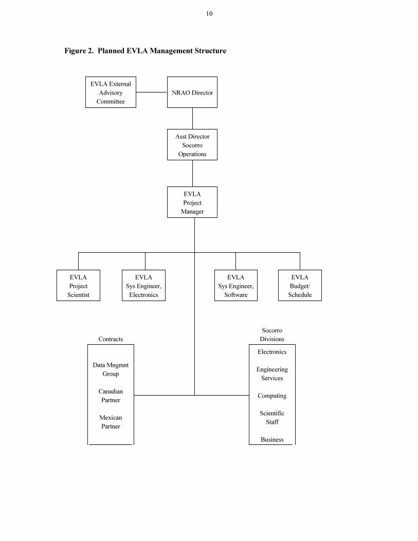
Figure 2. Planned EVLA Management Structure ................................................ 10
III. WORK BREAKDOWN STRUCTURE ..................................................................... 11
Table 2. EVLA Project WBS Level 2 Tasks......................................................... 11
IV. WORK PLAN............................................................................................................. 11
Table 3. EVLA Project Book Plan ........................................................................ 11
V. BUDGET...................................................................................................................... 12
Table 4. EVLA Project Budget ............................................................................ 13
VI. SCHEDULE................................................................................................................ 14
VII. EVLA PROJECT PERSONNEL.............................................................................. 17
Table 5. EVLA Personnel Requirements .............................................................. 17
APPENDIX A. PARTNERSHIP AGREEMENTS .......................................................... 18
Appendix A1 Memorandum of Understanding with Canadian Partner................ 18
Appendix A2 Letter from Mexican CONACYT................................................... 21
APPENDIX B. GUIDELINES FOR DESIGN REVIEWS .............................................. 22
APPENDIX C. DETAILED WORK BREAKDOWN STRUCTURE ............................. 24
APPENDIX D. PROJECT BOOK PLAN ........................................................................ 28
APPENDIX E. PROJECT BUDGET .............................................................................. 46
Appendix E1 An Example of an EVLA Cost Data Sheet .................................... 46
Appendix E2 Detailed Budget Plans for each Level 2 Task ................................. 47

1
I. OVERVIEW
1.1 Introduction
The goal of the Very Large Array Expansion (EVLA) Project is to improve most of the key observational capabilities of the Very Large Array (VLA) by at least an order of magnitude. The Project is divided into two Phases. Phase I will, by the application of modern technologies, improve the sensitivity, bandwidth, spectral resolution and frequency coverage of the existing 27 element array. Initial funding has been provided for planning and design of Phase I. Phase II will increase the angular resolution of the existing VLA by adding additional array elements around New Mexico. Also to be considered in Phase II are the addition of a condensed array configuration smaller than the existing D array and the addition of low frequency observing bands to the existing antennas. This Management Plan will describe only Phase I of the project. This Plan will be expanded to include Phase II when it becomes appropriate. The design, construction and operation of the EVLA is being carried out by the scientists, engineers and staff of the National Radio Astronomy Observatory (NRAO). The NRAO is a facility of the National Science Foundation (NSF) for research in radio astronomy; it is operated under a Cooperative Agreement5 by Associated Universities, Inc., (AUI). The EVLA has been endorsed by the Astronomy Decade Review6 for this decade and is described in the EVLA Proposal3 submitted to the NSF by AUI in May 2000. Additional information concerning the project was provided to the NSF by AUI in a document4 submitted in February 2001, in response to questions arising from the NSF Site Review held in Socorro on 14-15 December, 2000. This management plan updates and expands upon some of the material provided in that document 4. This plan addresses the design and construction of EVLA Phase I instrumentation and its installation on the VLA. 1.2 Objectives and Scope
1.2.1 Scientific Objectives The science which will be enabled by the EVLA has been described in detail in Appendix A of the Proposal3. In summary, the scientific objectives of the EVLA Phase I Project are to make an order of magnitude improvement in the key observational capabilities of the VLA, except for angular resolution, in order to enable a wide range of new scientific studies. Examples of some of the unique programs that will be made possible by the project include:
1Cooperative Agreement No AST9223814 between the National Science Foundation, Arlington, VA 22230 and Associated
Universities, Inc., Washington, D.C. 20036, dated January 1994. 2 C. McKee, J. Taylor “Astronomy and Astrophysics in the new millennium / Astronomy and Astrophysics Survey Committee,
Board on Physics and Astronomy-Space Studies Board, Commission on Physical Sciences, Mathematics, and Applications,
National Research Council. Washington, D.C.: National Academy Press, 2001. 3 VLA Expansion Project: Phase I The Ultrasensitive Array, proposal submitted to the National Science Foundation by
Associated Universities, Inc., May 2000. 4 VLA Expansion Project: Response to NSF Request for Additional Information, document submitted to the National Science
Foundation by Associated Universities, Inc., February 2000. 5 NRAO Environmental, Health and Safety Manual 6 NRAO New Mexico Environmental, Safety and Health Manual
2
�� providing accurate positions, sizes, and expansion estimates for up to 100 gamma-ray bursts every year
�� disentangling starburst from black hole activity in the early universe
�� mapping the magnetic fields in individual galaxy clusters
�� looking through the enshrouding dust to image the formation of high-redshift galaxies
�� observing ambipolar diffusion and thermal jet motions in young stellar objects
�� measuring the three-dimensional motions of ionized gas and stars in the center of the Galaxy
�� conducting unbiased searches for redshifted atomic and molecular absorption lines
�� measuring the three-dimensional structure of the magnetic field on the Sun
�� using the scattering of radio waves to map the changing structure of the dynamic heliosphere
�� measuring the rotation speeds of asteroids
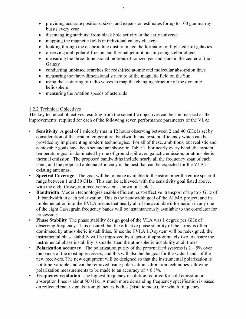
1.2.2 Technical Objectives The key technical objectives resulting from the scientific objectives can be summarized as the improvements required for each of the following seven performance parameters of the VLA: • Sensitivity A goal of 1 microJy rms in 12 hours observing between 2 and 40 GHz is set by
consideration of the system temperature, bandwidth, and system efficiency which can be provided by implementing modern technologies. For all of these, ambitious, but realistic and achievable goals have been set and are shown in Table 1. For nearly every band, the system temperature goal is dominated by one of ground spillover, galactic emission, or atmospheric thermal emission. The proposed bandwidths include nearly all the frequency span of each band, and the proposed antenna efficiency is the best that can be expected for the VLA’s existing antennas.
• Spectral Coverage The goal will be to make available to the astronomer the entire spectral range between 1 and 50 GHz. This can be achieved, with the sensitivity goal listed above, with the eight Cassegrain receiver systems shown in Table 1.
• Bandwidth Modern technologies enable efficient, cost-effective transport of up to 8 GHz of IF bandwidth in each polarization. This is the bandwidth goal of the ALMA project, and its implementation into the EVLA means that nearly all of the available information in any one of the eight Cassegrain frequency bands will be instantaneously available to the correlator for processing.
• Phase Stability The phase stability design goal of the VLA was 1 degree per GHz of observing frequency. This ensured that the effective phase stability of the array is often dominated by atmospheric instabilities. Since the EVLA LO system will be redesigned, the instrumental phase stability will be improved by a factor of approximately two to ensure the instrumental phase instability is smaller than the atmospheric instability at all times.
• Polarization accuracy The polarization purity of the present feed systems is 2 – 5% over the bands of the existing receivers, and this will also be the goal for the wider bands of the new receivers. The new equipment will be designed so that the instrumental polarization is not time-variable and can be removed using polarization calibration techniques, allowing polarization measurements to be made to an accuracy of < 0.1%.
• Frequency resolution The highest frequency resolution required for cold emission or absorption lines is about 500 Hz. A much more demanding frequency specification is based on reflected radar signals from planetary bodies (bistatic radar), for which frequency

3
resolution of about 1 Hz is desirable. The new correlator is designed to meet these specifications, as well as providing sufficient numbers of spectral channels to allow accurate measurement (and subsequent subtraction) of the surrounding continuum emission. This very high frequency resolution will also enable containment and removal of RFI signals within the observing bands.
• Bandpass Stability A key factor which limits the VLA’s ability to image weak spectral lines in the presence of strong continuum signals is the stability of the analog transmission link between the antennas and the correlator. The EVLA will employ a digital transmission system to improve bandpass stability by approximately an order of magnitude.
Table 1. Principal performance requirements for the EVLA Band Center
Frequency (GHz) Frequency Range
(GHz) System
Temperature (K) Total System
Efficiency Maximum IF
Bandwidth (GHz) 1.5 1.0-2.0 26 0.50 2x1
3.0 2.0-4.0 29 0.62 2x2
6.0 4.0-8.0 31 0.60 2x4
10 8.0-12.0 34 0.56 2x4
15 12.0-18.0 39 0.54 2x6
22 18.0-26.5 54 0.51 2x8
33 26.5-40.0 45 0.39 2x8
45 40.0-50.0 66* 0.34 2x8
* At low frequency end of the band
1.2.3 Project Objectives The project objective is to upgrade the VLA to provide the improved performance specified for the EVLA. This objective is to be achieved under the constraint that during the project, while the VLA is in transition to the EVLA, the VLA will remain in operation, except for short scheduled outages, with degradation to its scientific capabilities minimized to the extent possible. A summary of the major tasks to be carried out to reach the objective include the following:
�� Design, prototype and test on two antennas the new feeds, receivers and antenna structural modifications required to support the new EVLA observing bands.
�� Design, prototype and test on two antennas the new Intermediate Frequency (IF), Local Oscillator (LO) and Fiber Optic Transmission (FO) systems needed to support the new receiver bands and increased bandwidth of the EVLA.
�� After prototype testing, build and install on all VLA antennas all of the above listed equipment.
�� Design, build, test and install a new Monitor and Control (M/C) system, both hardware and software, to support the new EVLA equipment, including the correlator. The new M/C system must also allow operation of old and new antennas during the transition period.
�� Design, prototype, test, produce and commission a new correlator meeting EVLA requirements. The new correlator will be installed in a new correlator room in the VLA
4
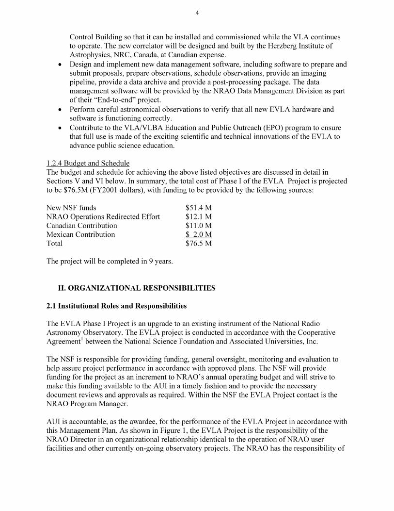
Control Building so that it can be installed and commissioned while the VLA continues to operate. The new correlator will be designed and built by the Herzberg Institute of Astrophysics, NRC, Canada, at Canadian expense.
�� Design and implement new data management software, including software to prepare and submit proposals, prepare observations, schedule observations, provide an imaging pipeline, provide a data archive and provide a post-processing package. The data management software will be provided by the NRAO Data Management Division as part of their “End-to-end” project.
�� Perform careful astronomical observations to verify that all new EVLA hardware and software is functioning correctly.
�� Contribute to the VLA/VLBA Education and Public Outreach (EPO) program to ensure that full use is made of the exciting scientific and technical innovations of the EVLA to advance public science education.
1.2.4 Budget and Schedule The budget and schedule for achieving the above listed objectives are discussed in detail in Sections V and VI below. In summary, the total cost of Phase I of the EVLA Project is projected to be $76.5M (FY2001 dollars), with funding to be provided by the following sources: New NSF funds $51.4 M NRAO Operations Redirected Effort $12.1 M Canadian Contribution $11.0 M Mexican Contribution $ 2.0 M Total $76.5 M The project will be completed in 9 years.
II. ORGANIZATIONAL RESPONSIBILITIES
2.1 Institutional Roles and Responsibilities
The EVLA Phase I Project is an upgrade to an existing instrument of the National Radio Astronomy Observatory. The EVLA project is conducted in accordance with the Cooperative Agreement1 between the National Science Foundation and Associated Universities, Inc. The NSF is responsible for providing funding, general oversight, monitoring and evaluation to help assure project performance in accordance with approved plans. The NSF will provide funding for the project as an increment to NRAO’s annual operating budget and will strive to make this funding available to the AUI in a timely fashion and to provide the necessary document reviews and approvals as required. Within the NSF the EVLA Project contact is the NRAO Program Manager. AUI is accountable, as the awardee, for the performance of the EVLA Project in accordance with this Management Plan. As shown in Figure 1, the EVLA Project is the responsibility of the NRAO Director in an organizational relationship identical to the operation of NRAO user facilities and other currently on-going observatory projects. The NRAO has the responsibility of
5
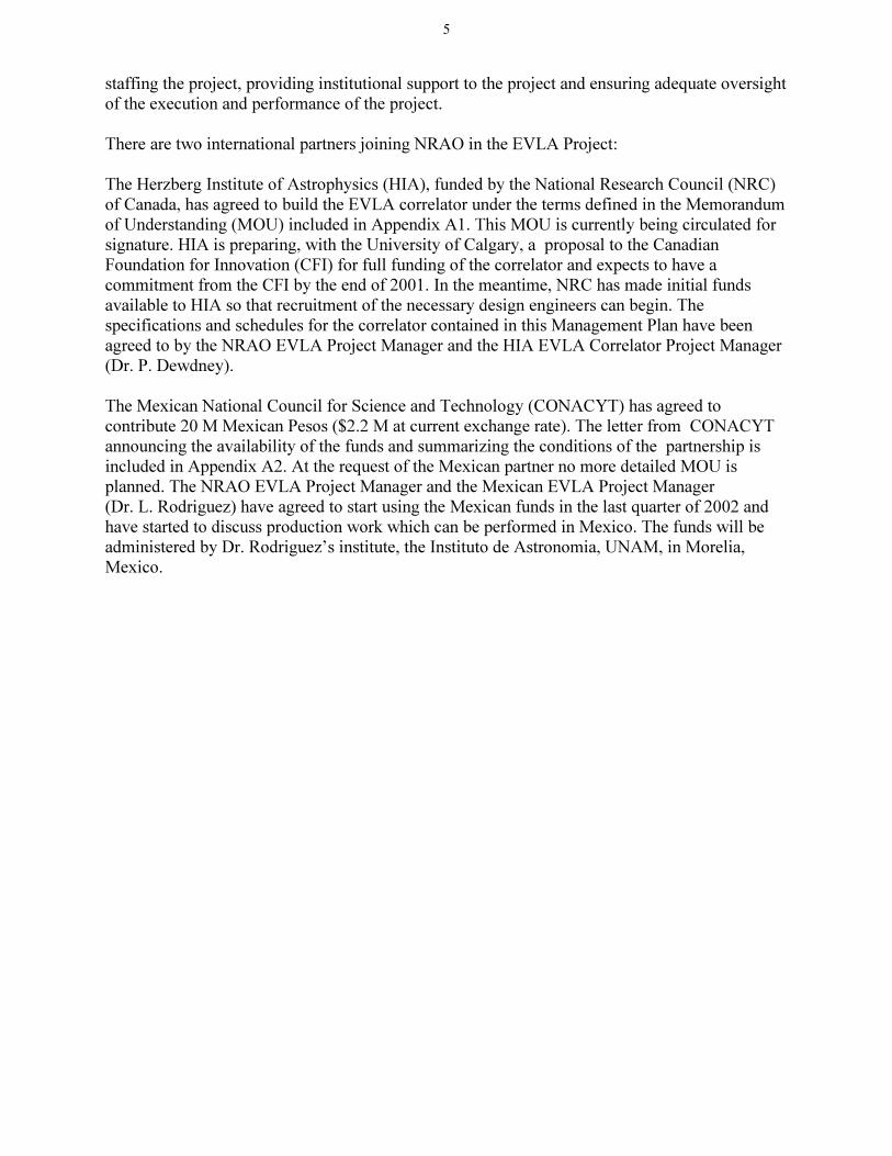
staffing the project, providing institutional support to the project and ensuring adequate oversight of the execution and performance of the project. There are two international partners joining NRAO in the EVLA Project: The Herzberg Institute of Astrophysics (HIA), funded by the National Research Council (NRC) of Canada, has agreed to build the EVLA correlator under the terms defined in the Memorandum of Understanding (MOU) included in Appendix A1. This MOU is currently being circulated for signature. HIA is preparing, with the University of Calgary, a proposal to the Canadian Foundation for Innovation (CFI) for full funding of the correlator and expects to have a commitment from the CFI by the end of 2001. In the meantime, NRC has made initial funds available to HIA so that recruitment of the necessary design engineers can begin. The specifications and schedules for the correlator contained in this Management Plan have been agreed to by the NRAO EVLA Project Manager and the HIA EVLA Correlator Project Manager (Dr. P. Dewdney). The Mexican National Council for Science and Technology (CONACYT) has agreed to contribute 20 M Mexican Pesos ($2.2 M at current exchange rate). The letter from CONACYT announcing the availability of the funds and summarizing the conditions of the partnership is included in Appendix A2. At the request of the Mexican partner no more detailed MOU is planned. The NRAO EVLA Project Manager and the Mexican EVLA Project Manager (Dr. L. Rodriguez) have agreed to start using the Mexican funds in the last quarter of 2002 and have started to discuss production work which can be performed in Mexico. The funds will be administered by Dr. Rodriguez’s institute, the Instituto de Astronomia, UNAM, in Morelia, Mexico.

6
Figure 1. NRAO Organization Chart
7
2.2 Oversight of the EVLA Project
Oversight of the EVLA Project will occur at a number of levels: AUI Board of Trustees
The Board will receive periodic reports from the Project Manager on the status of the Project. The NRAO Visiting Committee, which reviews the whole of NRAO for the Board, will review the status of the project at the annual Visiting Committee meetings. NRAO EVLA Advisory Committee
An advisory committee consisting of experienced scientists and engineers from outside of the NRAO will advise the NRAO Director on the scientific and technical priorities of the Project. Membership will include representation from the partner countries. This committee will be convened by the Project Scientist and will be chaired by one of its members and will meet once or twice a year. An important function of this committee will be oversight of the software aspects of the EVLA Project, so committee members will be chosen to provide expertise with astronomical software systems. This committee is currently being appointed. NRAO Users Committee
The NRAO Users’ Committee will be briefed on the EVLA at its annual meeting. This will be an important mechanism for the astronomical community to provide comment to the Project concerning the EVLA performance requirements and the plan for keeping the VLA in operation during the transition to the full EVLA. Reports to the NSF
Written quarterly reports to the NSF giving the technical and financial status of the project will be included as part of the NRAO Quarterly Report. Internal Advisory Committee
A committee of experienced NRAO scientists and engineers from outside the Project will provide advice to the Project Manager and Project Scientist concerning priorities and decisions. Membership will include the partner organizations. The committee will be convened by the Project Manager and chaired by one of its members. Design Reviews
Preliminary (PDR) and Critical Design Reviews (CDR) will be conducted for all hardware and software subsystems under Design Review Guidelines which will provide a balance of project and external review. The guidelines for execution of these Reviews are included in Appendix B. The reports of the reviews will be given to the reviewing bodies listed above and it will be the responsibility of the Project Manager to act on the findings of the reviews. 2.3 Organization of the EVLA Project
The relationship between the EVLA Project and the other operational units and projects at the NRAO is indicated in the NRAO organization chart shown in Figure 1. This shows that the EVLA Project, NRAO Data Management, and ALMA Project, each have their own management structure. The EVLA Project will be managed by a Project Manager reporting to the Assistant Director for Socorro Operations. The manpower resources required to accomplish the EVLA

8
tasks will be supplied by the existing Socorro Divisions with new positions added to these Divisions as necessary using EVLA Project funding. The Socorro Divisions will also continue to provide operations and maintenance support for the VLA and VLBA under the management of the two Socorro Deputy Assistant Directors. The EVLA Project organization is shown in more detail in Figure 2. The Socorro Electronics Division, Socorro Engineering Services Division, Socorro Computing Division, Socorro Business Division and Socorro Scientific Staff provide services to the EVLA Project as authorized and managed by the EVLA Project Manager. All expenditures of EVLA Project funds, either for new personnel positions or for materials and services, will be directly under the authority of the EVLA Project Manager. The allocation of personnel funded by the VLA Operations budget to EVLA tasks (the so-called “Redirected Effort” positions) will be negotiated by the EVLA Project Manager and the two Deputy Assistant Directors and will be documented in the EVLA and VLA Operations WBS’s. Personnel in the Redirected Effort category will be assigned to EVLA tasks according to the work plan approved by the EVLA Project Manager. Certain EVLA software tasks, will be performed by an NRAO Data Management team under contract to the EVLA Project. These contracts will be managed for the EVLA by the Socorro Computing Division Head. The activities of the Canadian and Mexican partners will be coordinated by the EVLA Project Manager as contracts to the EVLA project. Since all EVLA work will be carried out within the existing Socorro Divisions, it will be performed within the existing Safety Program already in place for NRAO's New Mexico activities. All NRAO rules concerning Environmental, Health and Safety regulations, reviews, oversight and enforcement will be followed for all EVLA work, as required by NRAO's Safety Manuals. (5,6) 2.3.1 Management Personnel The responsibilities of the key positions identified in Figure 2, and the names of the people currently assigned to these positions, are given below: NRAO Assistant Director for Socorro Operations (M. Goss)
Responsible for all NRAO activities associated with the operation and further development of the VLA and VLBA telescopes. EVLA Project Manager (P. Napier)
Overall responsibility for accomplishing the EVLA Project on budget and on time with all performance requirements achieved. Responsible for the execution of this management plan. EVLA Project Scientist (R. Perley)
Responsible for communicating with the scientific community, both inside and outside NRAO, to ensure that the performance requirements for the EVLA match the community’s priorities and maximize the scientific capabilities achievable with the available budget. EVLA Electronics Systems Engineer (J. Jackson)
Responsible for overview of the EVLA electronics system to ensure that the interfaces between all electronic subsystems are correct and that the design will ensure that all performance requirements will be met. Works closely with the EVLA Software Systems Engineer to ensure that all interfaces between hardware and software are correct. EVLA Software Systems Engineer (G. Hunt)
Responsible for overview of the EVLA software system to ensure that the interfaces between all software subsystems are correct and that the design will ensure that all performance requirements will be met. Works closely with the EVLA Electronics Systems Engineer to ensure that all interfaces between hardware and software are correct.
9
EVLA Schedule/Budget Planning (E. Cole)
Under the direction of the EVLA Project Manager, establishes and maintains the Project Work Breakdown Structure (WBS), Budget and Schedule. Socorro Electronics Division Head (C. Janes)
Responsible for the design and production of the Feed, Receiver, Local Oscillator, Intermediate Frequency and Data Transmission Subsystems required for the EVLA. Socorro Engineering Services Division Head (L. Serna)
Responsible for all modifications to the VLA antennas required for the EVLA. Socorro Scientific Staff Head (J. Ulvestad)
Responsible for all scientific studies required to set performance requirements for all hardware and software subsystems, and for all astronomical tests required for system commissioning and specification verification. Socorro Computing Division Head (G. van Moorsel)
Responsible for ensuring that software and computing hardware required for the EVLA is provided on schedule and budget. Supervises the Manager of the EVLA Monitor and Control Software team. Manages those software packages produced by the NRAO Data Management team as contracts to the EVLA Project. Socorro Business Division Head (S. Lagoyda)
Responsible for accomplishing all procurement activities required for the EVLA and for ensuring that these activities are carried out according to NRAO’s standard procurement regulations. Responsible for the preparation of the monthly Project Financial Statement. NRAO Associate Director for Data Management (T. Cornwell)
Responsible for the coordination of all Data Management software projects within NRAO. Manages the activities of the NRAO Data Management (DM) team. Responsible for those EVLA software packages provided by the NRAO DM team under contract from the EVLA Project. Canadian Partner Correlator Project Manager (P. Dewdney)
Responsible for the design and construction of the WIDAR (Wideband Interferometric Digital Architecture) correlator as the contribution of the Canadian Partner to the EVLA Project Mexican Partner Project Manager (L. Rodriguez)
Responsible for managing those components that are produced in Mexico as part of the contribution of the Mexican Partner to the EVLA Project, and for sending to the EVLA Project any remaining funds from the Mexican contribution.
10
NRAO Director
EVLA
Project
Scientist
EVLA
Sys Engineer,
Electronics
EVLA
Sys Engineer,
Software
EVLA
Budget/
Schedule
EVLA External
Advisory
Committee
Asst Director
Socorro
Operations
Contracts
Figure 2. Planned EVLA Management Structure
EVLA
Project
Manager
Data Mngmnt
Group
Canadian
Partner
Mexican
Partner
Electronics
Engineering
Services
Computing
Scientific
Staff
Business
Socorro
Divisions
11
III. WORK BREAKDOWN STRUCTURE (WBS)
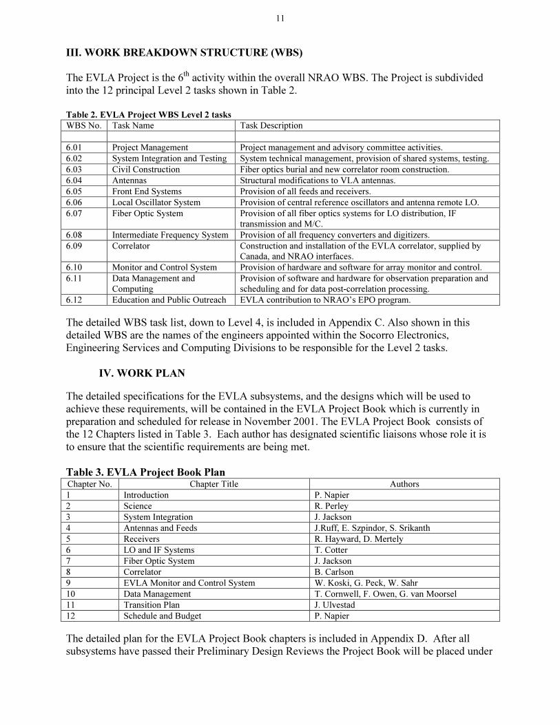
The EVLA Project is the 6th activity within the overall NRAO WBS. The Project is subdivided into the 12 principal Level 2 tasks shown in Table 2. Table 2. EVLA Project WBS Level 2 tasks
WBS No. Task Name Task Description
6.01 Project Management Project management and advisory committee activities.
6.02 System Integration and Testing System technical management, provision of shared systems, testing.
6.03 Civil Construction Fiber optics burial and new correlator room construction.
6.04 Antennas Structural modifications to VLA antennas.
6.05 Front End Systems Provision of all feeds and receivers.
6.06 Local Oscillator System Provision of central reference oscillators and antenna remote LO.
6.07 Fiber Optic System Provision of all fiber optics systems for LO distribution, IF
transmission and M/C.
6.08 Intermediate Frequency System Provision of all frequency converters and digitizers.
6.09 Correlator Construction and installation of the EVLA correlator, supplied by Canada, and NRAO interfaces.
6.10 Monitor and Control System Provision of hardware and software for array monitor and control.
6.11 Data Management and
Computing
Provision of software and hardware for observation preparation and
scheduling and for data post-correlation processing.
6.12 Education and Public Outreach EVLA contribution to NRAO’s EPO program.
The detailed WBS task list, down to Level 4, is included in Appendix C. Also shown in this detailed WBS are the names of the engineers appointed within the Socorro Electronics, Engineering Services and Computing Divisions to be responsible for the Level 2 tasks.
IV. WORK PLAN
The detailed specifications for the EVLA subsystems, and the designs which will be used to achieve these requirements, will be contained in the EVLA Project Book which is currently in preparation and scheduled for release in November 2001. The EVLA Project Book consists of the 12 Chapters listed in Table 3. Each author has designated scientific liaisons whose role it is to ensure that the scientific requirements are being met. Table 3. EVLA Project Book Plan Chapter No. Chapter Title Authors
1 Introduction P. Napier
2 Science R. Perley
3 System Integration J. Jackson
4 Antennas and Feeds J.Ruff, E. Szpindor, S. Srikanth
5 Receivers R. Hayward, D. Mertely
6 LO and IF Systems T. Cotter
7 Fiber Optic System J. Jackson
8 Correlator B. Carlson
9 EVLA Monitor and Control System W. Koski, G. Peck, W. Sahr
10 Data Management T. Cornwell, F. Owen, G. van Moorsel
11 Transition Plan J. Ulvestad
12 Schedule and Budget P. Napier
The detailed plan for the EVLA Project Book chapters is included in Appendix D. After all subsystems have passed their Preliminary Design Reviews the Project Book will be placed under

12
Change Control and changes will then be allowed only after approval of the EVLA Change Control Board. The EVLA Change Control Board will be chaired by the Project Manager and will include the EVLA Project Scientist and the two System Engineers.
V. BUDGET
The detailed budget for the EVLA Project was produced using a bottom-up process in which a WBS Cost Data Sheet was completed by the responsible engineer for every Level 3 and Level 4 entry in the WBS. The Cost Data Sheet contains estimates of the personnel and materials and services requirements needed to accomplish the defined task over the 9 year period of the EVLA project. An example of a completed EVLA Cost Data Sheet is included in Appendix E1. The summary budget for the EVLA Project, obtained by rolling up all of the detailed Cost Data Sheets, is shown below as Table 4. The detailed Budget Plans for each of the Level 2 Tasks is included in Appendix E2. Note that all budget numbers in this document are in FY 2001 dollars. Where necessary, conversion from FY 2000 dollars, the costing basis for the budget contained in the EVLA Proposal3 , to FY 2001 dollars has been made using the change in the Consumer Price Index (CPI). The CPI increased by 3% from FY2000 to FY2001. Thus, the total funds requested from the NSF in Table 3, $51.4 M (FY2001) is equivalent to the Proposal request of $49.9M (FY2000). In Table 4, the overall contingency level of 15% is the same as the level contained in the Proposal. This contingency will be held at two levels: i) the Project Manager, to be allocated as needed based on Change Board recommendations and ii) in a reserve held by the Observatory Director against unforeseen major problems, and/or opportunities, as requested by the Project Manager. In the event that additional contingency is required, a number of descope options are available with varying impact on the scientific performance of the EVLA. These options, which would reduce the sensitivity, bandwidth or frequency coverage of the EVLA, will remain open until the middle of 2004, when the quantity production of EVLA electronic equipment is scheduled to begin. By that time the budget risk should be significantly reduced because all design and prototype testing will be complete.

13
Table 4 EVLA Project Budget obtained by rolling up WBS Level 3 and Level 4 estimates
VLA EXPANSION PROJECT BUDGET
Note: All monetary amounts are listed in $k (FY2001)
2001 2002 2003 2004 2005 2006 2007 2008 2009 Sub-total
6.01 Project Management 76.1 119.1 169.1 220.3 177.8 155.6 144.4 99.8 40.8 1203
6.02
System Integration & Testing 268.2 572.2 88.4 52.1 44.1 44.1 42.6 26.6 24.6 1163
6.03 Civil Construction 0.0 770.4 221.0 145.0 445.0 40.0 0.0 0.0 0.0 1621
6.04
Antennas 47.7 222.2 725.6 432.7 242.3 196.3 155.0 149.4 15.2 2186
6.05 Front End Systems 239.4 460.8 1414.6 2602.9 1650.0 683.0 378.7 167.3 0.0 7597
6.06 Local Oscillator System 30.0 132.0 492.5 429.8 403.5 398.5 393.5 393.5 393.5 3067
6.07 Fiber Optic System 10.8 1084.4 1269.6 1044.3 924.3 924.3 824.3 700.0 0.0 6782
6.08 Intermediate Frequency System 20.0 494.0 499.0 586.0 586.0 586.0 586.0 586.0 586.0 4529
6.09 Correlator 149.0 366.3 159.3 622.3 38.3 4276.8 1879.0 45.0 17.0 7553
6.10 Monitor & Control System 19.2 367.9 441.1 406.4 255.0 237.7 204.3 172.1 64.0 2168
6.11 Data Management & Computing 0.0 10.3 114.5 266.5 85.5 33.0 184.0 126.0 526.0 1346
6.12 Education & Public Outreach 250.0 250.0 500
Sub-Total M&S
860 4600 5595 6808 4852 7542 5042 2716 1667 39715
NRAO Wages & Benefits 448 2915 3603 3612 2976 2544 2386 2288 1700 22470
Canadian Labor 54 383 641 490 468 365 624 321 136 3482
Total M&S+W/B 1362 7898 9838 10911 8296 10451 8051 5325 3503 65667
Contingency (15%) 204 1185 1476 1637 1244 1568 1208 799 525 9850
Redirected NRAO Effort -275 -1585 -2070 -2065 -1523 -1319 -1158 -1165 -857 -12019
Canadian Contribution -203 -749 -800 -1113 -506 -4642 -2503 -366 -153 -11035
Mexican Contribution -1000 -1000 -2000
ELVA Project Funds 1088 6748 7443 8370 7511 6057 5598 4592 3019 50464
AUI Fee 2% 22 135 149 167 150 121 112 92 60 1009
NSF Funded 1110 6883 7592 8537 7661 6178 5710 4684 3079 51473
2001 2002 2003 2004 2005 2006 2007 2008 2009

WBS Task Name Start Finish6.01 PROJECT MANAGEMENT 5/1/01 5/10/106.01.05 Management, Planning 5/1/01 5/10/106.01.05.05 Start Project 5/1/01 5/1/016.01.05.08 EVLA Operational 5/10/10 5/10/106.01.05.10 Detailed Project Mgmt Plan 6/4/01 9/7/016.01.06 Project Book 6/18/01 11/15/016.02 SYSTEM INTEGRATION AND TESTING 12/4/01 2/26/106.02.02 System PDR 12/4/01 12/4/016.02.03 System CDR 12/2/02 12/2/026.02.04 Transition [Commissioning] Plan 8/5/02 2/26/106.02.04.05 Start fiber cabling on Array 8/5/02 8/5/026.02.04.10 Install system on EVLA test antenna 4/1/03 4/1/036.02.04.15 Start interferometry tests - EVLA & VLA 7/1/03 7/1/036.02.04.20 Freeze electronics design/Start production 10/6/03 10/6/036.02.04.25 Start antenna outfitting 4/5/04 4/5/046.02.04.30 Prototype correlator tests begin 10/3/05 10/3/056.02.04.35 Begin new correlator room hardware outfitting 5/1/06 5/1/066.02.04.40 First new correlator tests 12/4/06 12/4/066.02.04.45 First shared risk observations 5/7/07 5/7/076.02.04.50 Full new correlator installed 2/4/08 2/4/086.02.04.55 Last antenna converted to EVLA Design 3/31/08 3/31/086.02.04.60 Completion of full new correlator tests 10/2/09 10/2/096.02.04.65 Final receiver installed 2/26/10 2/26/106.03 CIVIL CONSTRUCTION 8/1/02 10/1/076.03.05 Fiber Optic Cable 8/1/02 12/2/036.03.05.05 Trench & install FO cable (200kft) 8/1/02 12/2/036.03.10 New Correlator Room 1/3/05 10/1/076.04 ANTENNAS 2/13/02 3/31/086.04.01 Management/Subsystem Engineering 2/13/02 12/18/026.04.01.05 Feed Cone PDR 2/13/02 2/13/026.04.01.10 Feed Cone CDR 12/18/02 12/18/026.04.05 Feed Cone Production 3/17/03 3/31/086.04.05.03 Prototype structure available for test antenna 3/17/03 3/17/036.04.05.05 Start feed cone installation 4/5/04 4/5/046.04.05.50 Last antenna converted to EVLA Design 3/31/08 3/31/086.05 FRONT END SYSTEMS 2/12/02 2/26/106.05.01 Management/Subsystem Engineering 2/12/02 12/17/02
Q1 Q2 Q3 Q4 Q1 Q2 Q3 Q4 Q1 Q2 Q3 Q4 Q1 Q2 Q3 Q4 Q1 Q2 Q3 Q4 Q1 Q2 Q3 Q4 Q1 Q2 Q3 Q4 Q1 Q2 Q3 Q4 Q1 Q2 Q3 Q4 Q1 Q2 Q32001 2002 2003 2004 2005 2006 2007 2008 2009 2010
Task
Progress
Milestone
Summary
Rolled Up Task
Rolled Up Milestone
Rolled Up Progress
Split
External Tasks
Project Summary
Group By Summary
EVLA PROJECT9 Year Plan Summary
Page 1
Project: EVLA 9 yr planDate: 9/17/01
VI. SCHEDULE
The EVLA Project Summary Schedule, which identifies the major milestones for each of WBS Level 2 Tasks, is shown below:
14

WBS Task Name Start Finish6.05.01.05 Receiver/Feed PDR 2/12/02 2/12/026.05.01.10 Receiver/Feed CDR 12/17/02 12/17/026.05.05 Receiver Build & Installation 3/4/02 2/26/106.05.10 Feeds 3/4/02 6/23/066.06 LOCAL OSCILLATOR SYSTEMS 1/14/02 3/31/086.05.01 Management/Subsystem Engineering 1/14/02 1/13/036.06.01.05 LO/IF PDR 1/14/02 1/14/026.06.01.10 LO/IF CDR 1/13/03 1/13/036.06.05 LO production 1/13/03 3/31/086.07 FIBER OPTICS SYSTEM 12/10/01 3/31/086.07.01 Management/Subsystem Engineering 12/10/01 12/9/026.07.01.05 Fiber Optics System PDR 12/10/01 12/10/016.07.01.10 Fiber Optics System CDR 12/9/02 12/9/026.07.05 Fiber Optics System Production 12/10/01 4/1/036.07.10 Antenna Outfitting 3/1/04 3/31/086.08 INTERMEDIATE FREQUENCY SYSTEM 1/13/03 3/31/086.08.01 Management/Subsystem Engineering 1/13/03 3/31/086.08.05 Band Switches 1/13/03 1/14/036.08.10 Samplers 1/13/03 1/14/036.08.50 Last antenna converted to EVLA design 3/31/08 3/31/086.09 CORRELATOR 8/27/01 10/2/096.09.01 Management/Subsystem Engineering 8/27/01 10/2/096.09.01.05 New Correlator planning session 8/27/01 8/28/016.09.01.10 New Correlator Conceptual Design Review 11/2/01 11/2/016.09.01.15 User manual available 4/5/04 4/5/046.09.01.20 New Correlator PDR 7/16/04 7/16/046.09.01.25 New Correlator prototype testing w/ 3 baselines 10/3/05 10/3/056.09.01.30 New Correlator CDR 10/3/05 10/3/056.09.01.35 Start new Correlator installation 10/1/07 10/1/076.09.01.40 New Correlator operational 10/2/09 10/2/096.10 MONITOR AND CONTROL SYSTEM 2/1/02 9/11/096.10.01 Management/Subsystem Engineering 2/5/02 10/2/066.10.01.05 Monitor&Control Software PDR 2/6/02 2/6/026.10.01.10 Monitor&Control Hardware PDR 2/5/02 2/5/026.10.01.15 Monitor&Control Software CDR 1/7/03 1/7/036.10.01.20 Monitor&Control Hardware CDR 1/8/03 1/8/036.10.01.25 Full Monitor& Control capabilities available 3/15/04 3/15/04
Q1 Q2 Q3 Q4 Q1 Q2 Q3 Q4 Q1 Q2 Q3 Q4 Q1 Q2 Q3 Q4 Q1 Q2 Q3 Q4 Q1 Q2 Q3 Q4 Q1 Q2 Q3 Q4 Q1 Q2 Q3 Q4 Q1 Q2 Q3 Q4 Q1 Q2 Q32001 2002 2003 2004 2005 2006 2007 2008 2009 2010
Task
Progress
Milestone
Summary
Rolled Up Task
Rolled Up Milestone
Rolled Up Progress
Split
External Tasks
Project Summary
Group By Summary
EVLA PROJECT9 Year Plan Summary
Page 2
Project: EVLA 9 yr planDate: 9/17/01
15
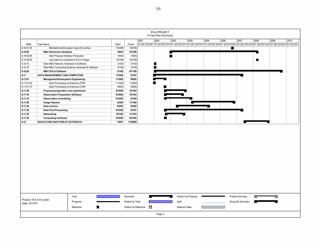
WBS Task Name Start Finish6.10.01.30 Monitor&Control system ready for archive 10/2/06 10/2/066.10.05 M&C Electronic Hardware 1/8/03 3/31/086.10.05.05 Start Physical Interface Production 1/8/03 1/8/036.10.05.50 Last antenna converted to EVLA Design 3/31/08 3/31/086.10.10 Start M&C Network, Hardware & Software 2/1/02 2/1/026.10.15 Start M&C Computing Systems Hardware & Software 2/1/02 2/1/026.10.20 M&C EVLA Software 2/1/02 9/11/096.11 DATA MANAGEMENT AND COMPUTING 1/15/02 5/1/076.11.01 Management/Subsystem Engineering 1/15/02 9/9/026.11.01.05 Data Processing Architecture PDR 1/15/02 1/15/026.11.01.10 Data Processing Architecture CDR 9/9/02 9/9/026.11.05 Proposal preparation and submission 9/10/02 12/1/036.11.10 Observation Preparation Software 9/10/02 10/1/036.11.15 Observation scheduling 9/10/02 4/1/046.11.20 Image Pipeline 5/3/04 11/1/066.11.25 Data archive 6/2/03 5/2/056.11.30 Data Post Processing 9/10/02 5/1/076.11.35 Networking 10/1/02 11/1/036.11.40 Computing hardware 9/10/02 9/12/026.12 EDUCATION AND PUBLIC OUTREACH 7/2/07 11/28/08
Q1 Q2 Q3 Q4 Q1 Q2 Q3 Q4 Q1 Q2 Q3 Q4 Q1 Q2 Q3 Q4 Q1 Q2 Q3 Q4 Q1 Q2 Q3 Q4 Q1 Q2 Q3 Q4 Q1 Q2 Q3 Q4 Q1 Q2 Q3 Q4 Q1 Q2 Q32001 2002 2003 2004 2005 2006 2007 2008 2009 2010
Task
Progress
Milestone
Summary
Rolled Up Task
Rolled Up Milestone
Rolled Up Progress
Split
External Tasks
Project Summary
Group By Summary
EVLA PROJECT9 Year Plan Summary
Page 3
Project: EVLA 9 yr planDate: 9/17/01
16
17
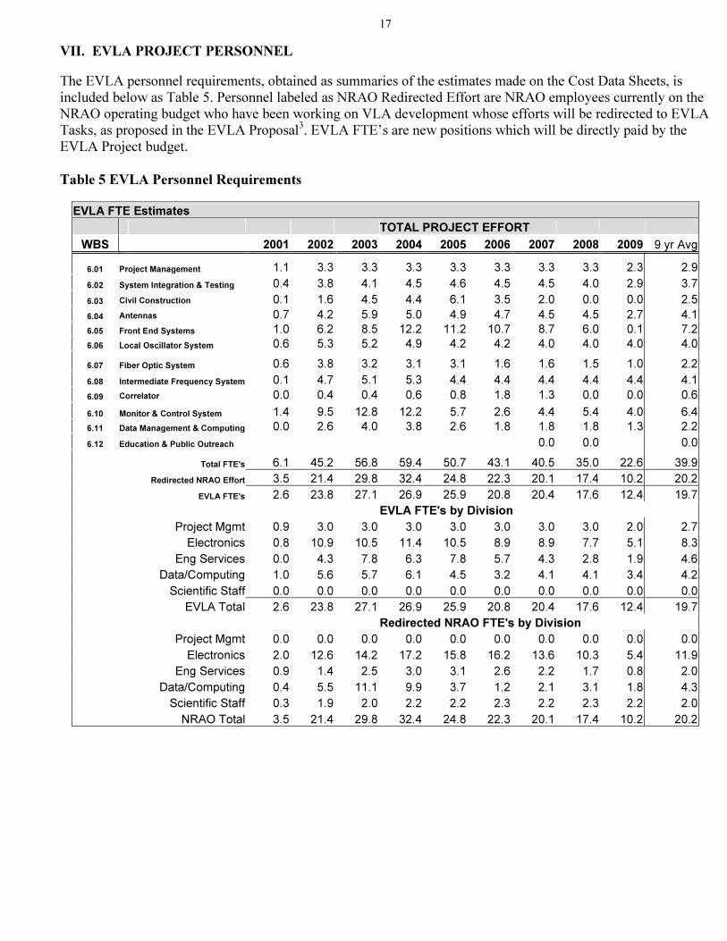
VII. EVLA PROJECT PERSONNEL
The EVLA personnel requirements, obtained as summaries of the estimates made on the Cost Data Sheets, is included below as Table 5. Personnel labeled as NRAO Redirected Effort are NRAO employees currently on the NRAO operating budget who have been working on VLA development whose efforts will be redirected to EVLA Tasks, as proposed in the EVLA Proposal3. EVLA FTE’s are new positions which will be directly paid by the EVLA Project budget. Table 5 EVLA Personnel Requirements
EVLA FTE Estimates
TOTAL PROJECT EFFORT
WBS 2001 2002 2003 2004 2005 2006 2007 2008 2009 9 yr Avg
6.01 Project Management 1.1 3.3 3.3 3.3 3.3 3.3 3.3 3.3 2.3 2.9
6.02 System Integration & Testing 0.4 3.8 4.1 4.5 4.6 4.5 4.5 4.0 2.9 3.7
6.03 Civil Construction 0.1 1.6 4.5 4.4 6.1 3.5 2.0 0.0 0.0 2.5
6.04 Antennas 0.7 4.2 5.9 5.0 4.9 4.7 4.5 4.5 2.7 4.1
6.05 Front End Systems 1.0 6.2 8.5 12.2 11.2 10.7 8.7 6.0 0.1 7.2
6.06 Local Oscillator System 0.6 5.3 5.2 4.9 4.2 4.2 4.0 4.0 4.0 4.0
6.07 Fiber Optic System 0.6 3.8 3.2 3.1 3.1 1.6 1.6 1.5 1.0 2.2
6.08 Intermediate Frequency System 0.1 4.7 5.1 5.3 4.4 4.4 4.4 4.4 4.4 4.1
6.09 Correlator 0.0 0.4 0.4 0.6 0.8 1.8 1.3 0.0 0.0 0.6
6.10 Monitor & Control System 1.4 9.5 12.8 12.2 5.7 2.6 4.4 5.4 4.0 6.4
6.11 Data Management & Computing 0.0 2.6 4.0 3.8 2.6 1.8 1.8 1.8 1.3 2.2
6.12 Education & Public Outreach 0.0 0.0 0.0
Total FTE's 6.1 45.2 56.8 59.4 50.7 43.1 40.5 35.0 22.6 39.9
Redirected NRAO Effort 3.5 21.4 29.8 32.4 24.8 22.3 20.1 17.4 10.2 20.2
EVLA FTE's 2.6 23.8 27.1 26.9 25.9 20.8 20.4 17.6 12.4 19.7
EVLA FTE's by Division
Project Mgmt 0.9 3.0 3.0 3.0 3.0 3.0 3.0 3.0 2.0 2.7
Electronics 0.8 10.9 10.5 11.4 10.5 8.9 8.9 7.7 5.1 8.3
Eng Services 0.0 4.3 7.8 6.3 7.8 5.7 4.3 2.8 1.9 4.6
Data/Computing 1.0 5.6 5.7 6.1 4.5 3.2 4.1 4.1 3.4 4.2
Scientific Staff 0.0 0.0 0.0 0.0 0.0 0.0 0.0 0.0 0.0 0.0
EVLA Total 2.6 23.8 27.1 26.9 25.9 20.8 20.4 17.6 12.4 19.7
Redirected NRAO FTE's by Division
Project Mgmt 0.0 0.0 0.0 0.0 0.0 0.0 0.0 0.0 0.0 0.0
Electronics 2.0 12.6 14.2 17.2 15.8 16.2 13.6 10.3 5.4 11.9
Eng Services 0.9 1.4 2.5 3.0 3.1 2.6 2.2 1.7 0.8 2.0
Data/Computing 0.4 5.5 11.1 9.9 3.7 1.2 2.1 3.1 1.8 4.3
Scientific Staff 0.3 1.9 2.0 2.2 2.2 2.3 2.2 2.3 2.2 2.0
NRAO Total 3.5 21.4 29.8 32.4 24.8 22.3 20.1 17.4 10.2 20.2
18
APPENDIX A. PARTNERSHIP AGREEMENTS
Appendix A1 Memorandum of Understanding With Canadian Partner
Memorandum of Understanding between the
Herzberg Institute of Astrophysics
and the
National Radio Astronomy Observatory
to establish a
North American Program in Radio Astronomy
Recognizing
�� that the purpose of the Herzberg Institute of Astrophysics (HIA), funded by the National Research Council (NRC) of Canada, is to conduct a broad program of research in ground-based astronomy;
�� that the purpose of the National Radio Astronomy Observatory (NRAO), operated by Associated Universities Inc.(AUI), funded by the National Science Foundation (NSF) of the United States, is to design, build, and operate large radio telescope facilities for the scientific community;
�� that the HIA has a strong program in centimeter-wavelength radio astronomy with a skilled team in the design and construction of signal correlators and an interest in long-term development work for the Square Kilometer Array (SKA);
�� that the NRAO has as a high priority the Very Large Array Expansion (EVLA) project, including the installation of a new signal correlator, as a step toward the development of the SKA; and
�� that the astronomical communities in the United States and Canada have a long tradition of close cooperation; and
Noting
�� the economic and technical advantages to the United States and Canada of establishing a joint venture for the design, development, and construction of instrumentation for the EVLA;
�� the scientific benefits of continuing to promote the policy of no national boundaries in applications for observing time on astronomical telescopes; and
�� the common scientific goals of our astronomical communities; HIA and NRAO
Resolve
�� to seek funds to contribute to the EVLA and if successful;
�� to establish the North American Program in Radio Astronomy (NAPRA) under the terms given in the following Articles of this Memorandum of Understanding (MOU).
Article 1. The signatories to this MOU are on the one hand, NRAO, and on the other hand, HIA.

19
Article 2. The duration of this partnership is for ten years, or through the first five years of operation of the new correlator to be installed at the VLA, whichever is longer. The partnership is renewable upon conclusion of mutually satisfactory negotiations between the participants and the concurrence of the funding agencies.
Article 3. The contributions to NAPRA of the participants are as follows:
In consideration of this MOU and the letter of intent signed in the year 2000 between NRC and NSF concerning a North American ALMA partnership, the NRAO will regard applications from scientists at Canadian institutes for telescope time on all its major telescopes, including ALMA, on the same basis as applications from scientists at institutions in the United States. Canada will contribute a new signal correlator to the EVLA to be built by HIA. The value of this correlator is expected to be approximately US$10,000,000. The formation of NAPRA is contingent upon NRC becoming a partner with NSF in ALMA, as described above. No contribution from Canada toward operations of the expanded VLA is expected. Work done in Canada and the United States toward the development of the SKA is to be recognized as a joint contribution.
Article 4. NRAO and NRC agree to explore possibilities of NRC participation in correlator design and
construction for future projects such as ALMA and the SKA. Any innovative correlator design features that result from HIA’s construction of the ELVA correlator may be incorporated into an ALMA correlator, if both signatories agree that it is of mutual benefit to do so.
Article 5. AUI/NRAO will recognize Canadian participation in NAPRA by appointing Canadians to relevant
advisory and governing bodies such as the AUI Board of Trustees and the NRAO Visiting, Program Advisory, and Users Committees. These appointments will be made in consultation with HIA.
Similarly, HIA will recognize US participation in NAPRA by appointing US representatives to advisory bodies relevant to correlators and SKA development.
Article 6. Canada will receive recognition in promotional material regarding the EVLA. Correspondingly, the
United States will be given recognition in promotional material for the SKA as a result of its contribution through NAPRA to the upgrade of the VLA, which is a first step to the SKA.
Article 7. NAPRA can be expanded by adding participants, on the same general principles set out in this MOU,
with the agreement by the signatories to revisions of the MOU. Article 8. The intention of the participants is that any intellectual property generated under NAPRA be available
to all participants for the NAPRA program, and that procurement procedures be openly conducted on both sides, without provisions that would unfairly impair the ability of industry on either side to compete.
Article 9. Activities conducted under NAPRA will be organized into projects, with defined scope, cost, and
schedule.
For the VLA Expansion, the leader of the Canadian component will coordinate with the NRAO EVLA Project Manager. The definition of requirements, specifications, and deliverables by Canada to the EVLA will be a joint activity of a team with representatives from the United States and Canada.

20
The United States will have representation on the corresponding body defining Canadian SKA development work. The specific management arrangements for these activities are to be detailed in a series of letters between the participants that achieve mutual agreement within six months of the signing of an agreement for the EVLA and SKA development work.
Article 10. While the intention is to make contributions to NAPRA in the form of deliverables rather than cash,
nothing in this MOU should be taken to exclude the possibility of cash exchanges in either direction when that would benefit the NAPRA activity and has the approval of the participants.
Article 11. Irresolvable disputes between the HIA and the NRAO will be referred to the funding agencies for resolution. Failure by the funding agencies to resolve a dispute within one year will result in automatic termination of the MOU. Should this occur before completion of the new VLA correlator, unfinished correlator hardware would be transferred to NRAO.
Signatories:
_____________________________ _______________________________ Simon Lilly, Director General Paul A. Vanden Bout, Director Herzberg Institute of Astrophysics National Radio Astronomy Observatory ____________________________ ________________________________ Date Date _______________________________ Riccardo Giacconi, President Associated Universities Inc. _______________________________ Date

22
APPENDIX B. GUIDELINES FOR DESIGN REVIEWS
EVLA PDR and CDR Definitions Version 2 - 2001-Jul-30 P. J. Napier Preliminary Design Review (PDR) To be held early enough in the Design Phase so that a change in direction is still possible if the need for such a change is identified by the review. The purpose of the PDR of an EVLA Subsystem is principally to review 3 questions:
(1) Are the top level performance requirements for the subsystem complete and adequate?
(2) Have the correct design solutions been selected for study and development during the EVLA Design Phase? Are there important alternate solutions that are not being studied?
(3) Has an adequate procurement plan been identified for the subsystem? The PDR will be organized and chaired by the EVLA Division Head responsible for the subsystem. The Review Board will include the following:
(a) At least 2 experts from outside the EVLA Project. In the event that the Review cannot be scheduled because of difficulty in arranging the attendance of a second expert, it will be acceptable to solicit the opinions of the second expert in writing after his/her review of all of the materials presented at the Review.
(b) The Project Manager and/or the Project Systems Engineer.
(c) The Project Scientist or his/her designee.
(d) At least one representative of any EVLA Division potentially impacted by the design of the subsystem.
Critical Design Review (CDR) To be held before expenditure of significant funds on the construction of production equipment which will be incorporated into the EVLA. The purpose of the CDR of an EVLA Subsystem is principally to review 4 questions:
(1) Are the detailed requirements for the subsystem complete and adequate?
(2) Will the design selected for implementation meet the requirements?
(3) Are interfaces to other subsystems defined adequately and completely?
(4) Has adequate attention been given to the produceability and maintainability of the subsystem? Meeting organization and attendance to be the same as a PDR.
23
Review Documentation (All Reviews)
(1) Minutes will be kept of the Review.
(2) As the last activity of the Review all Review Board members will be asked to answer the key questions and to identify any important Issues.
(3) The responsible Division Head must arrange for written responses to all Issues within one month of the
Review. These responses will become part of the Review documentation package.
(4) It is the responsibility of the EVLA Project Manager to determine what further action is required as follow-up to the Issues and Responses.

24
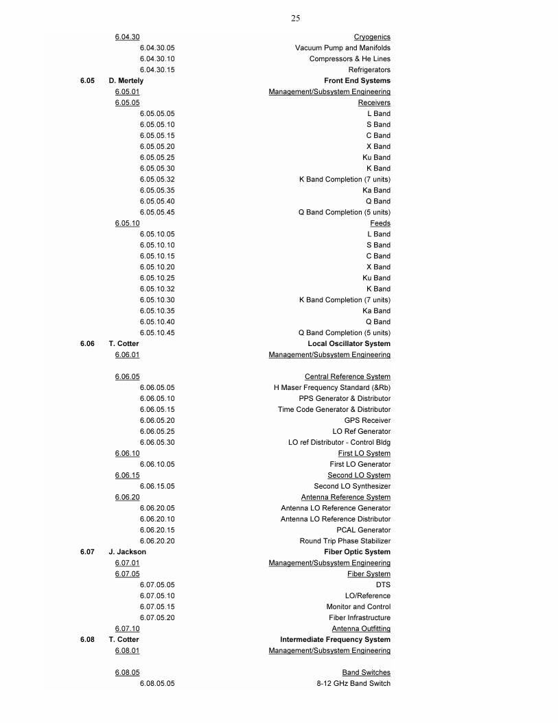
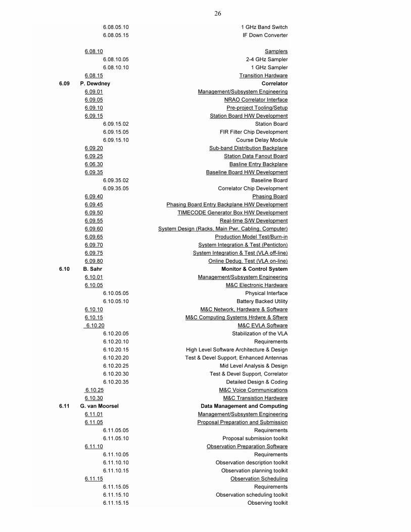
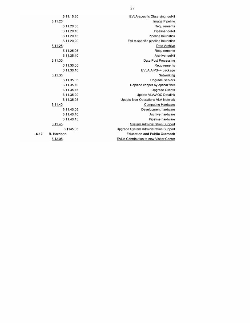
APPENDIX C. DETAILED WORK BREAKDOWN STRUCTURE EVLA WBS Level Four Summary
As of 8/29/01 8/30/01 9:09
ACDS# WBS TASK NAME
6.01 P. Napier Project Management
6.01.05 Management/Subsystem Engineering
6.01.06 Project Book
6.01.10 Office Equipment & Supplies
6.01.15 Drafting and Lab Services
6.01.20 Advisory Comm Support
6.02 J. Jackson System Integration and Testing
6.02.01 Management/Subsystem Engineering
6.02.05 Test and Lab Equipment
6.02.05.05 Production Test and Lab Equipment, FO
6.02.05.10 Production Test and Lab Equipment, FE
6.02.05.15 Production Test and Lab Equipment, LO
6.02.05.20 Test and Lab Equipment General
6.02.05.25 Engineering Software
6.02.10 Power Supply System
6.02.10.05 Central Electronics Room
6.02.10.10 Master LO Power Supply
6.02.10.15 Antenna Vertex Room Power Supply
6.02.10.20 Antenna Pedestal Room Power Supply
6.02.15 RFI Characterization
6.02.15.05 Shielded Chamber Development
6.02.15.10 RFI Survey and Analysis
6.02.15.15 Module RFI/EMC Analysis
6.02.15.20 Site RFI Mitigation
6.02.20 Scientific Support
6.02.20.05 Specification Development
6.02.20.10 Acceptance Test Development
6.02.25 Modules, Bins and Racks
6.02.30 Transition Planning
6.03 G. Stanzione Civil Construction
6.03.01 Management/Subsystem Engineering
6.03.05 FO Cable, Trench, Install
6.03.05.05 FO Cable, Trench and Install (200 kft)
6.03.05.10 FO Cable (550kft)
6.03.10 New Correlator Room
6.03.10.05 New Correlator Shielded Chamber
6.03.10.10 Remodeling and Demolition
6.03.10.15 Chiller
6.03.10.20 Power Distribution
6.03.10.25 Install New Correlator
6.03.15 IPG Shielded Chamber
6.03.20 Transition Planning
6.04 J. Ruff Antennas
6.04.01 Management/Subsystem Engineering
6.04.05 Feed Cone
6.04.05.05 Structure
6.04.05.10 HVAC
6.04.05.15 Electrical service
6.04.10 Antenna Structural Modifications
6.04.15 FRM for Prime focus Mock-up
6.04.20 Pointing Improvements
25
6.04.30 Cryogenics
6.04.30.05 Vacuum Pump and Manifolds
6.04.30.10 Compressors & He Lines
6.04.30.15 Refrigerators
6.05 D. Mertely Front End Systems
6.05.01 Management/Subsystem Engineering
6.05.05 Receivers
6.05.05.05 L Band
6.05.05.10 S Band
6.05.05.15 C Band
6.05.05.20 X Band
6.05.05.25 Ku Band
6.05.05.30 K Band
6.05.05.32 K Band Completion (7 units)
6.05.05.35 Ka Band
6.05.05.40 Q Band
6.05.05.45 Q Band Completion (5 units)
6.05.10 Feeds
6.05.10.05 L Band
6.05.10.10 S Band
6.05.10.15 C Band
6.05.10.20 X Band
6.05.10.25 Ku Band
6.05.10.32 K Band
6.05.10.30 K Band Completion (7 units)
6.05.10.35 Ka Band
6.05.10.40 Q Band
6.05.10.45 Q Band Completion (5 units)
6.06 T. Cotter Local Oscillator System
6.06.01 Management/Subsystem Engineering
6.06.05 Central Reference System
6.06.05.05 H Maser Frequency Standard (&Rb)
6.06.05.10 PPS Generator & Distributor
6.06.05.15 Time Code Generator & Distributor
6.06.05.20 GPS Receiver
6.06.05.25 LO Ref Generator
6.06.05.30 LO ref Distributor - Control Bldg
6.06.10 First LO System
6.06.10.05 First LO Generator
6.06.15 Second LO System
6.06.15.05 Second LO Synthesizer
6.06.20 Antenna Reference System
6.06.20.05 Antenna LO Reference Generator
6.06.20.10 Antenna LO Reference Distributor
6.06.20.15 PCAL Generator
6.06.20.20 Round Trip Phase Stabilizer
6.07 J. Jackson Fiber Optic System
6.07.01 Management/Subsystem Engineering
6.07.05 Fiber System
6.07.05.05 DTS
6.07.05.10 LO/Reference
6.07.05.15 Monitor and Control
6.07.05.20 Fiber Infrastructure
6.07.10 Antenna Outfitting
6.08 T. Cotter Intermediate Frequency System
6.08.01 Management/Subsystem Engineering
6.08.05 Band Switches
6.08.05.05 8-12 GHz Band Switch
26
6.08.05.10 1 GHz Band Switch
6.08.05.15 IF Down Converter
6.08.10 Samplers
6.08.10.05 2-4 GHz Sampler
6.08.10.10 1 GHz Sampler
6.08.15 Transition Hardware
6.09 P. Dewdney Correlator
6.09.01 Management/Subsystem Engineering
6.09.05 NRAO Correlator Interface
6.09.10 Pre-project Tooling/Setup
6.09.15 Station Board H/W Development
6.09.15.02 Station Board
6.09.15.05 FIR Filter Chip Development
6.09.15.10 Course Delay Module
6.09.20 Sub-band Distribution Backplane
6.09.25 Station Data Fanout Board
6.06.30 Basline Entry Backplane
6.09.35 Baseline Board H/W Development
6.09.35.02 Baseline Board
6.09.35.05 Correlator Chip Development
6.09.40 Phasing Board
6.09.45 Phasing Board Entry Backplane H/W Development
6.09.50 TIMECODE Generator Box H/W Development
6.09.55 Real-time S/W Development
6.09.60 System Design (Racks, Main Pwr, Cabling, Computer)
6.09.65 Production Model Test/Burn-in
6.09.70 System Integration & Test (Penticton)
6.09.75 System Integration & Test (VLA off-line)
6.09.80 Online Dedug, Test (VLA on-line)
6.10 B. Sahr Monitor & Control System
6.10.01 Management/Subsystem Engineering
6.10.05 M&C Electronic Hardware
6.10.05.05 Physical Interface
6.10.05.10 Battery Backed Utility
6.10.10 M&C Network, Hardware & Software
6.10.15 M&C Computing Systems Hrdwre & Sftwre
6.10.20 M&C EVLA Software
6.10.20.05 Stabilization of the VLA
6.10.20.10 Requirements
6.10.20.15 High Level Software Architecture & Design
6.10.20.20 Test & Devel Support, Enhanced Antennas
6.10.20.25 Mid Level Analysis & Design
6.10.20.30 Test & Devel Support, Correlator
6.10.20.35 Detailed Design & Coding
6.10.25 M&C Voice Communications
6.10.30 M&C Transistion Hardware
6.11 G. van Moorsel Data Management and Computing
6.11.01 Management/Subsystem Engineering
6.11.05 Proposal Preparation and Submission
6.11.05.05 Requirements
6.11.05.10 Proposal submission toolkit
6.11.10 Observation Preparation Software
6.11.10.05 Requirements
6.11.10.10 Observation description toolkit
6.11.10.15 Observation planning toolkit
6.11.15 Observation Scheduling
6.11.15.05 Requirements
6.11.15.10 Observation scheduling toolkit
6.11.15.15 Observing toolkit
27
6.11.15.20 EVLA-specific Observing toolkit
6.11.20 Image Pipeline
6.11.20.05 Requirements
6.11.20.10 Pipeline toolkit
6.11.20.15 Pipeline heuristics
6.11.20.20 EVLA-specific pipeline heuristics
6.11.25 Data Archive
6.11.25.05 Requirements
6.11.25.10 Archive toolkit
6.11.30 Data Post Processing
6.11.30.05 Requirements
6.11.30.10 EVLA AIPS++ package
6.11.35 Networking
6.11.35.05 Upgrade Servers
6.11.35.10 Replace copper by optical fiber
6.11.35.15 Upgrade Clients
6.11.35.20 Update VLA/AOC Datalink
6.11.35.25 Update Non-Operations VLA Network
6.11.40 Computing Hardware
6.11.40.05 Development hardware
6.11.40.10 Archive hardware
6.11.40.15 Pipeline hardware
6.11.45 System Administration Support
6.1145.05 Upgrade System Administration Support
6.12 R. Harrison Education and Public Outreach
6.12.05 EVLA Contribution to new Visitor Center
28
APPENDIX D. PROJECT BOOK PLAN
VLA Project Book, Chapter 1
EVLA Project Book:
Introduction
Peter Napier
Last changed 2001-Aug-01
Revision History:
2001-Aug-01: Initial release The goal of the Very Large Array Expansion (EVLA) Project is to improve most of the key observational capabilities of the Very Large Array (VLA) by at least an order of magnitude. The Project is divided into two Phases. Phase I will, by the application of modern technologies, improve the sensitivity, bandwidth, spectral resolution and frequency coverage of the existing 27 element array. Initial funding has been provided for Phase I and work has commenced on planning and design for this phase. Phase II will increase the angular resolution of the existing VLA by adding additional array elements around New Mexico. Also to be considered in Phase II are the addition of a condensed array configuration smaller than the existing D array and the addition of low frequency observing bands to the existing antennas. Initially, this Project Book will describe only the Phase I project. When the Phase II project commences, this book will be expanded to include it. This Project Book is intended to satisfy several functions. It is the principal description of the science requirements, the technical specifications, the design selected to achieve the specifications, the schedule on which tasks are to be accomplished, and the task responsibilities. Where one task interacts with another either in the design or integration, the interface requirements are specified. After an initial period of project definition, when all subsystems have completed Preliminary Design Review (PDR), the Project Book will be placed under configuration control. At that time specifications in the Project Book – technical specifications, interface specifications or schedule – will be controlled by EVLA System Engineering. Changes will not be made to the configuration without the process specified by System Engineering, through the Control Board, being followed and approval granted. The Project Book is the fundamental reference for what is, and is not, in the Project. As decisions are made and implemented those decisions will be incorporated into the Project Book. The Project Book is kept electronically and is always available on-line for reference by the Project and interested others. A revision history is included to aid change tracking. Although it is a living document and will evolve, it is at all times the current, and complete, Project configuration. Maintenance of the Project Book is the responsibility of EVLA Systems Engineering.
29
EVLA Project Book, Chapter 2
SCIENCE
Rick Perley
Last changed 2001-July-24 Revision History 2001-July-25: Initial release Summary 2.1 Some Key Scientific Experiments. 2.1.1 Gamma Ray Bursts 2.1.2 Separating starbursts from black holes in the early universe. 2.1.3 Mapping the detailed magnetic field structures within individual clusters of galaxies. 2.1.4 Imaging the formation of high-redshift galaxies behind the dusty screens which block most other
wavelengths. 2.1.5 Observing ambipolar diffusion and thermal jet structures in galactic young stellar objects. 2.1.6 Measuring the three-dimensional motion of ionized gas and stars in the center of our Galaxy. 2.1.7 Conducting unbiased searches for redshifted atomic and molecular absorption lines. 2.1.8 Measuring the three-dimensional structure of the magnetic fields on the Sun. 2.1.9 Mapping the changing structure of the dynamic heliosphere through measurements of angular
scattering of background radio sources. 2.1.10 Measuring the rotation speeds of asteroids. 2.2 Overall Technical Goals of the Project 2.2.1 Frequency Coverage. 2.2.2 Instantaneous Bandwidth. 2.2.3 Sensitivity. 2.2.4 System Linearity. 2.2.5 Antenna performance. 2.2.6 Electronic Phase and Amplitude Stability. 2.2.7 Correlator.
30
EVLA Project Book, Chapter 3.
SYSTEM INTEGRATION
Jim Jackson Last changed- 2001 July-19
Revision History
2001-July-19: Initial release Summary 3.1 Introduction 3.2 Specifications and Requirements 3.2.1 Frequency and Polarization Coverage 3.2.2 Tuning Capabilities 3.2.3 External RFI 3.2.4 Self Generated RFI 3.2.5 Monitor and Control 3.2.6 Correlator 3.2.7 Computing System 3.2.8 Antennas 3.3 System Block Diagrams 3.3.1 Antenna RF/LO/IF Electronics 3.3.2 CEB LO/IF Electronics 3.3.3 Correlator 3.3.4 Monitor Control System 3.3.5 Computing System 3.3.6 Antenna Drive System 3.4 Acceptance Testing 3.4.1 Test Definition 3.4.2 Test Procedure Development 3.4.3 System Testing 3.4.4 Test Result Documentation & Reporting 3.5 Hardware Development 3.5.1 Test and Laboratory Equipment 3.5.2 Engineering Design and Test Software 3.5.3 Hardware Design Standards 3.5.4 Hardware Environmental Requirements 3.5.5 Antenna Racks, Bins and Modules 3.5.6 CEB Racks, Bins and Modules 3.6 System Software Development 3.6.1 Software Design Standards 3.6.2 Computing Platform(s) 3.6.3 Computer/Network Security 3.7 System Power Supplies 3.7.1 Antenna Electronics Systems 3.7.2 CEB Electronics Systems 3.7.3 Correlator 3.7.4 Computing and Network Hardware 3.8 RFI Testing 3.8.1 Environmental Monitoring System 3.8.2 System Hardware Emission Testing Facilities

31
EVLA Project Book, Chapter 4
ANTENNAS AND FEEDS
Jim Ruff, Ed Szpindor, S. Srikanth Last changed 2001-August 14
Revision History:
2001-August 14: Initial release Summary: 4.1 Introduction 4.2 Requirements 4.2.1 Mechanical/Structural/Electrical 4.2.2 Feeds and Optics 4.2.2.1 Overview 4.2.2.2 Polarization 4.2.2.3 Polarization Purity 4.2.2.4 Feed Circle Layout 4.2.2.5 Mechanical/Physical 4.2.2.6 Design Flexibility 4.2.3 Safety 4.2.4 RFI 4.2.5 Cabling 4.3 Design Concepts/Specifications 4.3.1 Feed Cone 4.3.2 Structure 4.3.2.1 Structural Modifications 4.3.2.2 FRRM for Prime Focus (prototype) 4.3.2.3 Pointing Improvements 4.3.4 HVAC 4.3.5 Electrical Service 4.3.6 Feeds 4.3.6.1 General Specifications for Feeds 4.3.6.2 L-Band Feed (1.0-2.0 GHz) 4.3.6.3 S-Band Feed (2.0-4.0 GHz) 4.3.6.4 C-Band Feed (4.0-8.0 GHz) 4.3.6.5 X-Band Feed (8.0-12.0 GHz) 4.3.6.6 Ku-Band Feed (12.0-18.0 GHz) 4.3.6.7 K-Band Feed (18.0-26.5 GHz) 4.3.6.8 Ka-Band Feed (26.5-40.0 GHz) 4.3.6.9 Q-Band Feed (40.0-50.0 GHz) 4.3.7 References:
32
EVLA Project Book, Chapter 5.
RECEIVERS
Robert Hayward and Daniel J. Mertely
Last changed 2001 July-01 Revision History 2001-July-01: Initial release
Summary (L Band) 5.1 Introduction 5.1.1 Specifications and Requirements 5.1.1.1 Frequency Coverage 5.1.1.2 Instantaneous Bandwidth 5.1.1.3 Receiver Temperature 5.1.1.4 Dynamic Range 5.1.1.5 LO Input 5.1.1.5.1 LO Input Frequencies 5.1.1.5.2 LO Input Purity 5.1.1.5.3 LO Input Power Levels 5.1.1.6 RF Output Power 5.1.1.7 AC Input Power 5.1.1.8 DC Input Power 5.1.1.9 Total Power Dissipation 5.1.1.10 Cryogenics 5.1.1.10.1 Refrigerator 5.1.1.10.2 Compressor 5.1.2 Current Design 5.1.3 Test Results 5.1.4 References Summary (S Band) 5.2 Introduction 5.2.1 Specifications and Requirements 5.2.1.1 Frequency Coverage 5.2.1.2 Instantaneous Bandwidth 5.2.1.3 Receiver Temperature 5.2.1.4 Dynamic Range 5.2.1.5 LO Input 5.2.1.5.1 LO Input Frequencies 5.2.1.5.2 LO Input Purity 5.2.1.5.3 LO Input Power Levels 5.2.1.6 RF Output Power 5.2.1.7 AC Power 5.2.1.8 DC Input Power 5.2.1.9 Power Dissipation 5.2.1.10 Cryogenics 5.2.1.10.1 Refrigerator 5.2.1.10.2 Compressor
33
5.2.2 Current Design 5.2.3 Test Results 5.2.4 References Summary (C Band) 5.3 Introduction 5.3.1 Specifications and Requirements 5.3.1.1 Frequency Coverage 5.3.1.2 Instantaneous Bandwidth 5.3.1.3 Receiver Temperature 5.3.1.4 Dynamic Range 5.3.1.5 LO Input 5.3.1.5.1 Dynamic LO Input Frequencies 5.3.1.5.2 LO Input Purity 5.3.1.5.3 LO Input Power Levels 5.3.1.6 RF Output Power 5.3.1.7 AC Input Power 5.3.1.8 DC Input Power 5.3.1.9 Power Dissipation 5.3.1.10 Cryogenics 5.3.1.10.1 Refrigerator 5.3.1.10.2 Compressor 5.3.2 Current Design 5.3.3 Test Results 5.3.4 References Summary ( X Band) 5.4 Introduction 5.4.1 Specifications and Requirements 5.4.1.1 Frequency Coverage 5.4.1.2 Instantaneous Bandwidth 5.4.1.3 Receiver Temperature 5.4.1.4 Dynamic Range 5.4.1.5 LO Input 5.4.1.5.1 LO Input Frequencies 5.4.1.5.2 LO Input Purity 5.4.1.5.3 LO Input Power Levels 5.4.1.6 RF Output Power 5.4.1.7 AC Input Power 5.4.1.8 DC Input Power 5.4.1.9 Power Dissipation 5.4.1.10 Cryogenics 5.4.1.10.1 Refrigerator 5.4.1.10.2 Compressor 5.4.2 Current Design 5.4.3 Test Results 5.4.4 References Summary (Ku Band) 5.5 Introduction 5.5.1 Specifications and Requirements 5.5.1.1 Frequency Coverage
34
5.5.1.2 Instantaneous Bandwidth 5.5.1.3 Receiver Temperature 5.5.1.4 Dynamic Range 5.5.1.5 LO Input 5.5.1.5.1 LO Input frequencies 5.5.1.5.2 LO Input Purity 5.5.1.5.3 LO Input Power Levels 5.5.1.6 RF Output Power 5.5.1.7 AC Input Power 5.5.1.8 DC Input Power 5.5.1.9 Power Dissipation 5.5.1.10 Cryogenics 5.5.1.10.1 Refrigerator 5.5.1.10.2 Compressor 5.5.2 Current Design 5.5.3 Test Results 5.5.4 References Summary (K Band) 5.6 Introduction 5.6.1 Specifications and Requirements 5.6.1.1 Frequency Coverage 5.6.1.2 Instantaneous Bandwidth 5.6.1.3 Receiver Temperature 5.6.1.4 Dynamic Range 5.6.1.5 LO Input 5.6.1.5.1 LO Input Frequencies 5.6.1.5.2 LO Input Purity 5.6.1.5.3 LO Input Power Levels 5.6.1.6 RF Output Power 5.6.1.7 AC Input Power 5.6.1.8 DC Input Power 5.6.1.9 Power Dissipation 5.6.1.10 Cryogenics 5.6.1.10.1 Refrigerator 5.6.1.10.2 Compressor 5.6.2 Current Design 5.6.3 Test Results 5.6.4 References Summary (K-Band Completion) 5.7 Introduction 5.7.1 Specifications and Requirements 5.7.1.1 Frequency Coverage 5.7.1.2 Instantaneous Bandwidth 5.7.1.3 Receiver Temperature 5.7.1.4 Dynamic Range 5.7.1.5 LO Input 5.7.1.5.1 LO Input Frequencies 5.7.1.5.2 LO Input Purity 5.7.1.5.3 LO Input Power Levels 5.7.1.6 RF Output Power
35
5.7.1.7 AC Input Power 5.7.1.8 DC Input Power 5.7.1.9 Power Dissipation 5.7.1.10 Cryogenics 5.7.1.10.1 Refrigerator 5.7.1.10.2 Compressor 5.7.2 Current Design 5.7.3 Test Results 5.7.4 References Summary (Ka Band) 5.8 Introduction 5.8.1 Specifications and Requirements 5.8.1.1 Frequency Coverage 5.8.1.2 Instantaneous Bandwidth 5.8.1.3 Receiver Temperature 5.8.1.4 Dynamic Range 5.8.1.5 LO Input 5.8.1.5.1 LO Input Frequencies 5.8.1.5.2 LO Input Purity 5.8.1.5.3 LO Input Power Levels 5.8.1.6 Output Power 5.8.1.7 AC Input Power 5.8.1.8 DC Input Power 5.8.1.9 Power Dissipation 5.8.1.10 Cryogenics 5.8.1.10.1 Refrigerator 5.8.1.10.2 Compressor 5.8.2 Current Design 5.8.3 Test Results 5.8.4 References Summary (Q Band) 5.9 Introduction 5.9.1 Specifications and Requirements 5.9.1.1 Frequency Coverage 5.9.1.2 Instantaneous Bandwidth 5.9.1.3 Receiver Temperature 5.9.1.4 Dynamic Range 5.9.1.5 LO Input 5.9.1.5.1 LO Input Frequencies 5.9.1.5.2 LO Input Purity 5.9.1.5.3 LO Input Power Levels 5.9.1.6 RF Output Power 5.9.1.7 AC Input Power 5.9.1.8 DC Input Power 5.9.1.9 Power Dissipation 5.9.1.10 Cryogenics 5.9.1.10.1 Refrigerator 5.9.1.10.2 Compressor 5.9.2 Current Design 5.9.3 Test Results

36
5.9.4 References Summary (Q-Band Completion) 5.10 Introduction 5.10.1 Specifications and Requirements 5.10.1.1 Frequency Coverage 5.10.1.2 Instantaneous Bandwidth 5.10.1.3 Receiver Temperature 5.10.1.4 Dynamic Range 5.10.1.5 LO Input 5.10.1.5.1 LO Input Frequencies 5.10.1.5.2 LO Input Purity 5.10.1.5.3 LO Input Power Levels 5.10.1.6 RF Output Power 5.10.1.7 AC Input Power 5.10.1.8 Input Power 5.10.1.9 Power Dissipation 5.10.1.10 Cryogenics 5.10.1.10.1 Refrigerator 5.10.1.10.2 Compressor 5.10.2 Current Design 5.10.3 Test Results 5.10.4 References
37
EVLA Project Book, Chapter 6
LOCAL OSCILLATOR AND INTERMEDIATE FREQUENCY SYSTEMS
Terry Cotter
Last changed 2001-June-20 Revision History: 2001 -July-20: Initial Release Summary 6.1 Introduction 6.2 Specifications and Requirements 6.3 Environmental 6.4 General Module Interface 6.5 LO Phase Error 6.5.1 LO Phase Noise Allocation 6.5.2 Phase Drift Allocation 6.6 Fringe Tracking, Phase Switching, Sideband Suppression Table 6.6 Fringe Generator Requirements 6.7 RFI 6.8 Mechanical 6.9 Central Reference System 6.9.1 Frequency Standards Table 6.9.1a Principle Performance Requirements of the H-maser Table 6.9.1b Principle Performance Requirements of the Rubidium Oscillator 6.9.2 Timing Generator 6.9.3 GPS Receiver 6.9.4 LO Ref Generator Table 6.9.4 Reference Generator Frequencies 6.9.5 LO Ref Distributor 6.10 First LO System 6.10.1 First LO Synthesizer 6.11 Second LO System 6.11.1 Second LO Synthesizer 6.11.2 Fringe Generator 6.12 Antenna Reference System 6.12.1 Antenna LO Reference Generator 6.12.2 Antenna LO Reference Distributor 6.13 PCAL Generator 6.14 Intermediate Frequency System 6.14.1 Band Switches 6.14.2 8-12 GHz Band Switch 6.14.3 1 GHz Band Switch 6.14.4 IF Down Converter 6.15 Samplers 6.15.1 2-4 GHz Sampler 6.15.2 1 GHz Sampler 6.16 Transition Hardware 6.16.1 Transition Sampler 6.16.2 Transition Digital to Analog Converter 6.16.3 Transition Down Converter 6.16.4 Transition X-Band Converter
38
EVLA Project Book, Chapter 7
FIBER OPTICS SYTEM
Jim Jackson
Last Changed 19-July-2001
Revision History
2001-July-19: Initial release
Summary 7.1 Introduction 7.2 Digital IF Data Transmission System 7.2.1 Specifications and Requirements 7.2.2 Transmission Protocol 7.2.3 Transmitter (Antenna) Hardware Design 7.2.3.1 Block Diagrams 7.2.3.2 Power Supplies 7.2.3.3 Field Programmable Gate Array 7.2.3.4 OC192 Multiplexer 7.2.3.5 Opto-Electronics 7.2.3.6 Physical Packaging 7.2.3.7 Manufacture and Assembly 7.2.4 Receiver (CEB) Hardware Design 7.2.4.1 Block Diagrams 7.2.4.2 Power Supplies 7.2.4.3 Field Programmable Gate Array 7.2.4.4 OC192 Demultiplexer 7.2.4.5 Opto-Electronics 7.2.4.6 Physical Packaging 7.2.4.7 Manufacture and Assembly 7.2.5 Optics and WDM Systems 7.2.6 IF Signal Interfaces 7.2.7 Reference Signal Interfaces 7.2.8 Monitor Control Interface 7.2.9 Power Supply Interfaces 7.2.10 Cooling Requirements 7.3 LO Reference Distribution System 7.3.1 Specifications and Requirements 7.3.2 Round Trip Phase Correction Scheme 7.3.3 Transmitter (CEB) Hardware Design 7.3.3.1 Block Diagrams 7.3.3.2 Power Supplies 7.3.3.3 Electronics Design 7.3.3.4 Optical Design 7.3.3.5 Physical Packaging 7.3.3.6 Manufacture and Assembly 7.3.4 Receiver (Antenna) Hardware Design 7.3.4.1 Block Diagrams 7.3.4.2 Power Supplies 7.3.4.3 Electronics Design
39
7.3.4.4 Optical Design 7.3.4.5 Physical Packaging 7.3.4.6 Manufacture and Assembly 7.3.5 Signal Interfaces 7.3.6 Monitor Control Interface 7.3.7 Power Supply Interface 7.3.8 Cooling Requirements 7.4 Monitor Control System (Antenna & CEB electronics systems) 7.4.1 Specifications and Requirements 7.4.2 Block Diagram 7.4.3 Commercial Optical Networking Hardware 7.4.4 Interfaces 7.4.5 Procurement and Assembly 7.5 Fiber Infrastructure 7.5.1 Specifications and Requirements 7.5.1.1 Fiber Optic Routing and Sparing Philosophy 7.5.1.2 Fiber Optic Cable Thermal Considerations 7.5.2 Fiber Plant Block Diagrams 7.5.2.1 IF Data Transmission System 7.5.2.2 LO/Reference Systems 7.5.2.3 Monitor & Control Systems 7.5.2.4 Direct M&C (Safety – old WYEMON) 7.5.2.5 Voice Comms (phone system) 7.5.3 Fiber Optic Cable Specification 7.5.3.1 CEB Interior Fiber Optic Cable 7.5.3.2 Under Ground Fiber Optic Cable 7.5.3.3 Antenna/Pad Interconnect Cable 7.5.3.4 Antenna Internal Cables 7.5.3.5 Antenna Cable Wrap Cables 7.5.4 Fiber Optic Cable Management Hardware 7.5.4.1 Patch Panels 7.5.4.2 CEB Interior 7.5.4.3 CEB Cable Penetration Point(s) 7.5.4.4 Direct Buried Splices 7.5.4.5 Underground Vault Splices 7.5.4.6 Antenna to Pad Connections 7.5.4.7 Antenna Pedestal Room 7.5.4.8 Antenna Azimuth Cable Wrap 7.5.4.9 Antenna Elevation Cable Wrap 7.5.4.10 Antenna Vertex Room 7.5.4.11 Antenna Apex 7.5.5 Fiber Optic and Laser Safety Requirements and Procedures 7.5.5.1 OSHA Safety Requirements 7.5.5.2 Laser Safety Training, Certification and Vision Testing 7.5.5.3 Fiber Optic Cable Accessibility (Planned and Accidental) 7.5.5.4 Fiber Optic Cable Fire Safety requirements 7.5.6 Fiber Optic Installation Standards and Procedures 7.5.7 Fiber Optic Cable Repair Standards and Procedures

40
EVLA Project Book, Chapter 8. CORRELATOR
Brent Carlson Last changed 2001-June-06
Revision History:
2001-August 14: Initial release.
Summary Table 8-1 EVLA correlator principal performance specifications. Table 8-2 EVLA correlator development milestones 8.1 Introduction 8.2 Specifications 8.2.1 Number of Stations (Antennas) 8.2.2 Spectral Channel Capability 8.2.3 Polarization 8.2.4 Sampled Baseband Capacity 8.2.5 Baseband Tuning 8.2.6 Digital Sub-band Capability 8.2.7 Sub-band Stitching 8.2.8 Sub-band Bandwidth 8.2.9 Sub-band Tuning Flexibility 8.2.10 Sample Word Sizes and Correlator Efficiency 8.2.11 Correlator Chip 8.2.12 Digital FIR Filter Chip 8.2.13 Radar Mode 8.2.14 Pulsar Processing 8.2.15 Real-Time Data Output Performance 8.2.16 Delay 8.2.17 Doppler/Frequency Shift 8.2.18 Sub-arrays 8.2.19 Phased-VLA 8.2.20 Auto-correlations and Data Statistics 8.2.21 VLBI 8.2.22 Maintenance 8.2.23 Interference Mitigation 8.2.24 System Timing 8.2.25 Computing and Data Highways 8.2.26 Environment 8.3 Correlator Architecture 8.3.1 System Overview Figure 8-1 Simplified correlator system block diagram. 8.3.2 System Module Connectivity Figure 8-2 Correlator module connectivity diagram. 8.3.3 System Network Topology 8.3.4 System Installation Figure 8-3 Possible baseline subsystem back-end computing/network topology. Figure 8-4 Preliminary correlator system floorplan. 8.4 Deliverables Table 8-3 Cost estimates for NRC-supplied correlator deliverables Table 8-4 Additional (NRAO supplied) correlator deliverables 8.5 Interfaces and Impacts on Other Systems

41
Table 8-5 Table of correlator interfaces and potential impacts on other systems 8.6 Risk Assessment
Table 8-6 Areas of risk, and planned risk mitigation strategies in descending order of importance. 8.7 References
42
EVLA Project Book, Chapter 9
EVLA MONITOR AND CONTROL SYSTEM
Wayne Koski, George Peck, William Sahr
Last changed 2001-July-16
Revision History 2001-July-16: Initial release Summary 9.1 Introduction 9.2 Specifications and Requirements 9.2.1 Scientific Requirements 9.2.2 Engineering Requirements 9.2.3 Operational Requirements 9.3 Design Considerations 9.3.1 General 9.3.2 Command & Control Requirements 9.3.2.1 Hard Real-Time Deadlines 9.3.3 Monitor Data Requirements 9.3.3.1 Hard Real-Time Deadlines 9.3.4 Real Time Failure Detection 9.3.5 Backup Monitor & Control System 9.3.6 Correlator Monitor & Control 9.3.7 Monitor & Control of the Hybrid Array 9.3.8 Storage, Retrieval, & Analysis of Historical Monitor Data 9.4 Data Rates 9.5 Conceptual Design 9.5.1 Array Control Computer 9.5.2 Antenna Computer 9.5.2.1 Location and Number of Antenna Computers 9.5.2.2 Antenna Objects 9.5.3 Module Interface Board 9.5.3.1 Hardware 9.5.3.2 Software 9.5.3.2.1 Protocols 9.5.3.2.2 Real-Time Kernal &/or Software Libraries 9.5.4 EVLA Monitor and Control Network 9.5.4.1 Within the Control Building 9.5.4.2 From the Control Building to the Antennas 9.5.4.3 Within an Antenna 9.5.4.4 Remote Access 9.6 VLA to EVLA Transition 9.6.1 Control of Modified VLA Antennas (EVLA Antennas) 9.6.2 Interfacing EVLA Antennas to the Current (VLA) Correlator 9.6.3 Switchover to the EVLA Correlator 9.6.4 Coordination & Communication Between the VLA & EVLA Monitor & Control Systems

43
EVLA Project Book, Chapter 10
DATA MANAGEMENT
Tim Cornwell, Frazer Owen, and Gustaaf van Moorsel Last changed 2001-July-18
Revision history
2001-July-18: Initial version Summary 10.1 Conceptual Design 10.1.1 Common Operational Model 10.1.2 Proposal Submission Toolkit 10.1.3 Observation Description Toolkit 10.1.4 Observation Planning Toolkit 10.1.5 Observation Scheduling Toolkit 10.1.6 Observing Toolkit 10.1.7 Archive toolkit 10.1.8 Pipeline Toolkit 10.1.9 Pipeline Heuristics 10.1.10 Calibration Toolkit 10.2 Interfaces to other EVLA sub-systems 10.3 Construction plans 10.4 References
44
EVLA Project Book, Chapter 11
Transition Plan
Jim Ulve
Last changed 2001-Au
Revision History
2001-Aug-15: Initial Release Summary
11.1 Introduction 11.2 Scientific & Operational Requirements 11.2.1 Scientific Availability 11.2.1.1 Stand-alone Observing 11.2.1.2 VLBI Observing 11.2.1.3 Pie Town Link Observing 11.2.2 Antenna and Array Availability 11.2.2.1 General Availability 11.2.2.2 EVLA Antennas 11.2.3 Array Operations and Documentation 11.2.3.1 Routine Operations 11.2.3.2 EVLA Tests 11.2.3.3 EVLA Documentation 11.2.4 Data Management and Data Analysis 11.2.4.1 Scheduling 11.2.4.2 Data Pipeline and Analysis Soft 11.2.4.3 Data Calibration 11.2.4.4 Data Archive 11.2.5 VLA Infrastructure 11.2.6 Personnel Safety 11.3 Antenna/Feed/Receiver Plan 11.4 Electronics Plan 11.4.1 EVLA Antennas with VLA Correlator 11.4.2 New/Old IF/LO Systems 11.5 Monitor & Control Plan 11.6 Correlator Plan 11.7 Interim Operations Plan 11.8 Schedule

45
EVLA ProjectBook,Chapter 12
Peter J. NaLast changed 2001-July
SCHEDULE AND BUDGET
Revision History 2001-July –23: Initial release 12.1 Introduction 12.2 Schedule and Budget 12.3 Project Work Breakdown Structure 12.4 Project Schedule 12.5 Project Budget
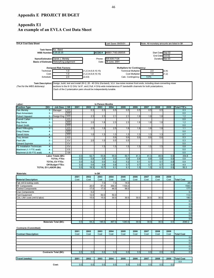
46
Appendix E PROJECT BUDGET
Appendix E1
An example of an EVLA Cost Data Sheet
EVLA Cost Data Sheet Last Saved09/05/01 Note: All monetary amounts are listed in $K
Task Name: Ka - Band
WBS Number: 6.05.05.35 ACDS # 46801.7183.050535 Start Date
End Date
Name/Estimator: Phone: Duration
Basis of Estimate: Date:
Assigned Risk Factors: Multipliers for Contingency:
Technical (1,2,3,4,6,8,10,15) Technical Multiplier: (2,4)
Cost (1,2,3,4,6,8,10,15) Cost Multiplier: (1,2)
Schedule (2,4,8) Calc. Contingency.: 5.0%
Task Description: Design, build, test and install 28+2, 26 - 40 GHz (Ka-band), VLA low-noise receiver front ends, including down-converting mixer
(Text for the WBS dictionary) sections to the 8-12 GHz 1st IF, and 2 full, 4 GHz-wide instantaneous IF bandwidth channels for both polarizations.
Each of the 2 polarization pairs should be independently tunable.
Labor: In Person Months
Position Type SG Job Desc SS 2001 2002 2003 2004 2005 2006 2007 2008 2009 Total FTE's
Dan Mertely 3 Manager ED 0.3 0.3 0.5 0.5 0.5 0.5 0.5 0.3
Raul Armendariz 3 ED 0.0
Robert Hayward 3 Design Eng ED 2.3 2.3 2.1 2.1 1.8 1.8 1.8 1.2
Everett Callan 3 ED 0.0
Rey Serna 3 ED 2.0 1.8 2.3 2.3 1.8 1.8 1.8 1.2
Robert Smith 3 ED 0.0
Brent Willoughby 3 ED 2.0 1.8 2.5 1.8 1.8 1.8 1.8 1.1
Greg Chavez 4 ED 0.0
Darrell Hicks 4 ED 1.0 1.3 1.3 1.3 1.3 1.3 1.3 0.7
Troy Jensen 4 ED 0.6 0.6 0.6 0.6 0.6 0.3
Paul Lilie 2 EV 2.0 1.0 0.5 0.5 0.3
Edward Szpindor 3 EV 0.0
FE Installation Technicain 4 EV 1.5 1.5 1.5 1.5 1.5 1.5 0.8
Machinist (1.1 FTE avail) 4 ES 0.0
Machinist (0.55 FTE avail) 4 GB 0.0
Labor Totals ($K): 0.0 62.7 53.8 55.0 50.7 41.3 41.3 49.9 0.0 354.8
TOTAL FTEs: 0.0 0.8 0.8 0.9 0.9 0.8 0.8 0.8 0.0 5.8
TOTAL EV FTEs: 0.0 0.2 0.0 0.2 0.2 0.1 0.1 0.1 0.0 0.9
Off Budget FTEs: 0.0 0.6 0.8 0.8 0.7 0.7 0.7 0.7 0.0 4.9
TOTAL EV LABOR ($k): 0.0 18.3 10.7 6.1 6.1 1.5 1.5 6.1 0.0 50.3
Materials: In $K
2001 2002 2003 2004 2005 2006 2007 2008 2009
Material Description: Cost Cost Cost Cost Cost Cost Cost Cost Cost Total Cost
7.0 7.0 14.0 28.0
20.0 57.0 366.0 1100.0 1543.0
17.0 17.0 44.0 99.0 177.0
0.2 0.2
12.0 50.0 50.0 112.0
15.0 15.0 30.0 30.0 30.0 30.0 30.0 180.0
0.0
0.0
0.0
0.0
0.0
0.0
0.0
Materials Total ($K): 0.0 64.2 146.0 497.0 1243.0 30.0 30.0 30.0 0.0 2040.2
Contracts (Committed):
2001 2002 2003 2004 2005 2006 2007 2008 2009
Contract Description: Cost Cost Cost Cost Cost Cost Cost Cost Cost Total Cost
0.0
0.0
0.0
0.0
0.0
Contracts Total ($K): 0.0 0.0 0.0 0.0 0.0 0.0 0.0 0.0 0.0 0.0
Travel (weeks): 2001 2002 2003 2004 2005 2006 2007 2008 2009 Total Cost
0.0
Cost: 0.0 0.0 0.0 0.0 0.0 0.0 0.0 0.0 0.0
Sep-02
Oct-02
Daniel J. Mertely 505 835-7128 Mar-00
History/Eng judgement 28 June, 2001
1.0 2.0
1.0 1.0
2.0
Fab mtl & tooling costs
RF Components
Control Components
Cryo Components
Test Equipment
CDL LNA costs (mtl & labor)

47
Appendix E2 Detailed Budget Plans for each Level 2 Task.
Note: All monetary amounts are listed in $k (FY2001)
6.01 Project Management
2001
2002
2003
2004
2005
2006
2007
2008
2009
Sub-total
6.01.05 Mgmt/Subsystem Eng
25.0
40.0
60.0
75.0
70.0
68.0
60.0
55.0
30.0
483.0
6.01.06
Project Book
0.3
0.8
1.0
1.2
0.7
0.5
0.5
1.0
6.0
6.01.10
Office Equipment & Supplies
20.0
36.2
53.0
74.0
36.0
18.0
30.8
2.0
270.0
6.01.15
Drafting and Lab Services
5.0
7.0
10.0
10.0
8.0
12.0
3.0
1.0
56.0
6.01.20
Advisory Comm Support
15.0
20.0
30.0
45.0
48.0
42.0
35.0
30.0
265.0
Sub-Total M&S
65.3
104.0
154.0
205.2
162.7
140.5
129.3
89.0
30.0
1080.0
Travel
10.8
15.1
15.1
15.1
15.1
15.1
15.1
10.8
10.8
123.0
Sub-total M&S+T
76.1
119.1
169.1
220.3
177.8
155.6
144.4
99.8
40.8
1203.0
Labor
131.5
269.4
269.4
269.4
269.4
269.4
269.4
269.4
216.5
2233.8
Sub-Total
M&S+T+L
207.6
388.5
438.5
489.7
447.2
425.0
413.8
369.2
257.3
3436.8
Redirected Ops
Effort
-27.5
-27.5
-27.5
-27.5
-27.5
-27.5
-27.5
-27.5
-27.5
-247.5
Total
180.1
361.0
411.0
462.2
419.7
397.5
386.3
341.7
229.8
3189.3
EVLA FTE's:
0.8
3.0
3.0
3.0
3.0
3.0
3.0
3.0
2.0
23.8
Off Budget FTE's:
0.2
0.2
0.2
0.2
0.2
0.2
0.2
0.2
0.2
2.2
Total FTE's
1.1
3.2
3.2
3.2
3.2
3.2
3.2
3.2
2.2
26.1
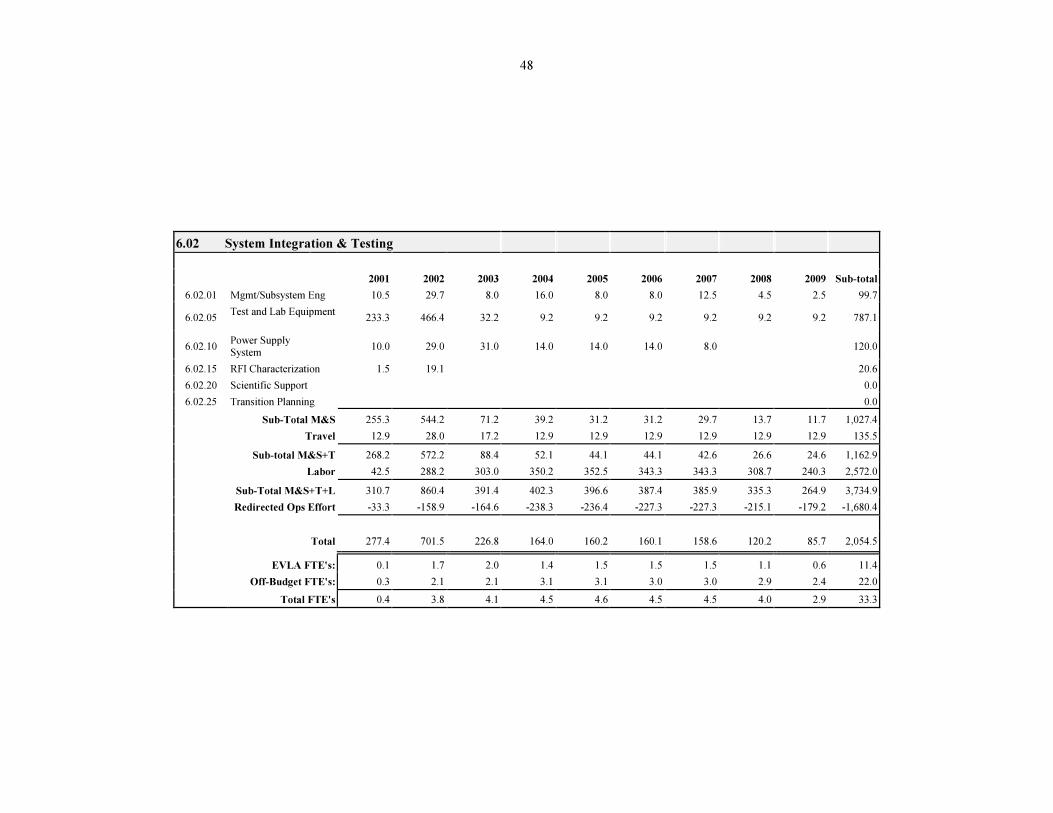
48
6.02 System Integration & Testing
2001
2002
2003
2004
2005
2006
2007
2008
2009
Sub-total
6.02.01
Mgmt/Subsystem Eng
10.5
29.7
8.0
16.0
8.0
8.0
12.5
4.5
2.5
99.7
6.02.05
Test and Lab Equipment
233.3
466.4
32.2
9.2
9.2
9.2
9.2
9.2
9.2
787.1
6.02.10
Power Supply System
10.0
29.0
31.0
14.0
14.0
14.0
8.0
120.0
6.02.15
RFI Characterization
1.5
19.1
20.6
6.02.20
Scientific Support
0.0
6.02.25
Transition Planning
0.0
Sub-Total M&S
255.3
544.2
71.2
39.2
31.2
31.2
29.7
13.7
11.7
1,027.4
Travel
12.9
28.0
17.2
12.9
12.9
12.9
12.9
12.9
12.9
135.5
Sub-total M&S+T
268.2
572.2
88.4
52.1
44.1
44.1
42.6
26.6
24.6
1,162.9
Labor
42.5
288.2
303.0
350.2
352.5
343.3
343.3
308.7
240.3
2,572.0
Sub-Total M&S+T+L
310.7
860.4
391.4
402.3
396.6
387.4
385.9
335.3
264.9
3,734.9
Redirected Ops Effort
-33.3
-158.9
-164.6
-238.3
-236.4
-227.3
-227.3
-215.1
-179.2
-1,680.4
Total
277.4
701.5
226.8
164.0
160.2
160.1
158.6
120.2
85.7
2,054.5
EVLA FTE's:
0.1
1.7
2.0
1.4
1.5
1.5
1.5
1.1
0.6
11.4
Off-Budget FTE's:
0.3
2.1
2.1
3.1
3.1
3.0
3.0
2.9
2.4
22.0
Total FTE's
0.4
3.8
4.1
4.5
4.6
4.5
4.5
4.0
2.9
33.3

49
6.03 Civil Construction
2001
2002
2003
2004
2005
2006
2007
2008
2009
Sub-total
6.03.05
FO Cable, Trench, Install
760.4
221.0
981.4
6.03.10
New Correlator Room
145.0
445.0
40.0
630.0
6.03.15
IPG Shielded Chamber
10.0
10.0
6.03.20
Transition Planning
0.0
Sub-Total M&S
0.0
770.4
221.0
145.0
445.0
40.0
0.0
0.0
0.0
1621.4
Travel
Sub-total M&S+T
0.0
770.4
221.0
145.0
445.0
40.0
0.0
0.0
0.0
1621.4
Labor
9.4
55
179.4
204.4
263.5
150.5
79.4
941.6
Sub-Total M&S+T+L
9.4
825.4
400.4
349.4
708.5
190.5
79.4
0.0
0.0
4184.4
Redirected Ops Effort
-9.4
-6.1
-32.8
-57.8
-68
-41.9
-30.5
-246.5
Total
0.0
819.3
367.6
291.6
640.5
148.6
48.9
0.0
0.0
3937.9
EVLA FTE's:
0.0
1.5
4.0
3.5
5.0
2.8
1.5
0.0
0.0
18.3
Off-Budget FTE's:
0.1
0.1
0.5
0.9
1.1
0.7
0.5
0.0
0.0
3.8
Total FTE's
0.1
1.6
4.5
4.4
6.1
3.5
2.0
0.0
0.0
22.2

50
6.04 Antennas
2001
2002
2003
2004
2005
2006
2007
2008
2009
Sub-total
6.04.01 Mgmt/Subsystem Eng
0.2
8.5
32.0
8.0
8.2
8.5
12.0
8.0
8.2
93.6
6.04.05
Feed Cone
45.0
228.0
102.0
52.0
32.0
22.0
17.0
498.0
6.04.10
Antenna Structural Modifications
52.0
12.0
15.0
15.0
15.0
12.0
12.0
133.0
6.04.15
FRM for Prime focus Mock-up
130.0
40.0
170.0
6.04.20
Pointing Improvements
69.0
79.0
65.0
10.0
223.0
6.04.30
Cryogenics
47.5
43.3
240.3
202.7
157.1
140.8
109.0
112.4
7.0
1060.1
Sub-Total M&S
47.7
217.8
721.3
432.7
242.3
196.3
155.0
149.4
15.2
2177.7
Travel
4.4
4.3
8.7
Sub-total M&S+T
47.7
222.2
725.6
432.7
242.3
196.3
155.0
149.4
15.2
2186.4
Labor
36
191.7
226.3
226.3
220.2
222.9
210.7
210.7
144.9
1689.7
Sub-Total
M&S+T+L
83.7
413.9
951.9
659.0
462.5
419.2
365.7
360.1
160.1
3876.1
Redirected Ops
Effort
-36
-161.9
-188.3
-188.3
-182.2
-182.2
-170
-170
-106.9
-1385.8
Total
47.7
252.0
763.6
470.7
280.3
237.0
195.7
190.1
53.2
2490.3
EVLA FTE's:
0.0
1.8
2.8
1.8
1.8
1.8
1.8
1.8
0.9
14.8
Off-Budget FTE's:
0.7
2.3
3.0
3.1
3.0
2.9
2.7
2.7
1.8
22.1
Total FTE's
0.7
4.2
5.9
5.0
4.9
4.7
4.5
4.5
2.7
36.9
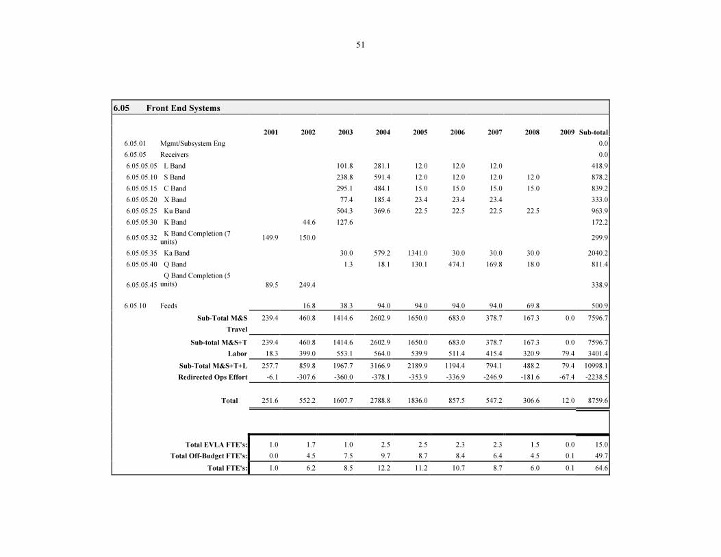
51
6.05 Front End Systems
2001
2002
2003
2004
2005
2006
2007
2008
2009
Sub-total
6.05.01
Mgmt/Subsystem Eng
0.0
6.05.05
Receivers
0.0
6.05.05.05
L Band
101.8
281.1
12.0
12.0
12.0
418.9
6.05.05.10
S Band
238.8
591.4
12.0
12.0
12.0
12.0
878.2
6.05.05.15
C Band
295.1
484.1
15.0
15.0
15.0
15.0
839.2
6.05.05.20
X Band
77.4
185.4
23.4
23.4
23.4
333.0
6.05.05.25
Ku Band
504.3
369.6
22.5
22.5
22.5
22.5
963.9
6.05.05.30
K Band
44.6
127.6
172.2
6.05.05.32
K Band Completion (7 units)
149.9
150.0
299.9
6.05.05.35
Ka Band
30.0
579.2
1341.0
30.0
30.0
30.0
2040.2
6.05.05.40
Q Band
1.3
18.1
130.1
474.1
169.8
18.0
811.4
6.05.05.45
Q Band Completion (5
units)
89.5
249.4
338.9
6.05.10
Feeds
16.8
38.3
94.0
94.0
94.0
94.0
69.8
500.9
Sub-Total M&S
239.4
460.8
1414.6
2602.9
1650.0
683.0
378.7
167.3
0.0
7596.7
Travel
Sub-total M&S+T
239.4
460.8
1414.6
2602.9
1650.0
683.0
378.7
167.3
0.0
7596.7
Labor
18.3
399.0
553.1
564.0
539.9
511.4
415.4
320.9
79.4
3401.4
Sub-Total M&S+T+L
257.7
859.8
1967.7
3166.9
2189.9
1194.4
794.1
488.2
79.4
10998.1
Redirected Ops Effort
-6.1
-307.6
-360.0
-378.1
-353.9
-336.9
-246.9
-181.6
-67.4
-2238.5
Total
251.6
552.2
1607.7
2788.8
1836.0
857.5
547.2
306.6
12.0
8759.6
Total EVLA FTE's:
1.0
1.7
1.0
2.5
2.5
2.3
2.3
1.5
0.0
15.0
Total Off-Budget FTE's:
0.0
4.5
7.5
9.7
8.7
8.4
6.4
4.5
0.1
49.7
Total FTE's:
1.0
6.2
8.5
12.2
11.2
10.7
8.7
6.0
0.1
64.6
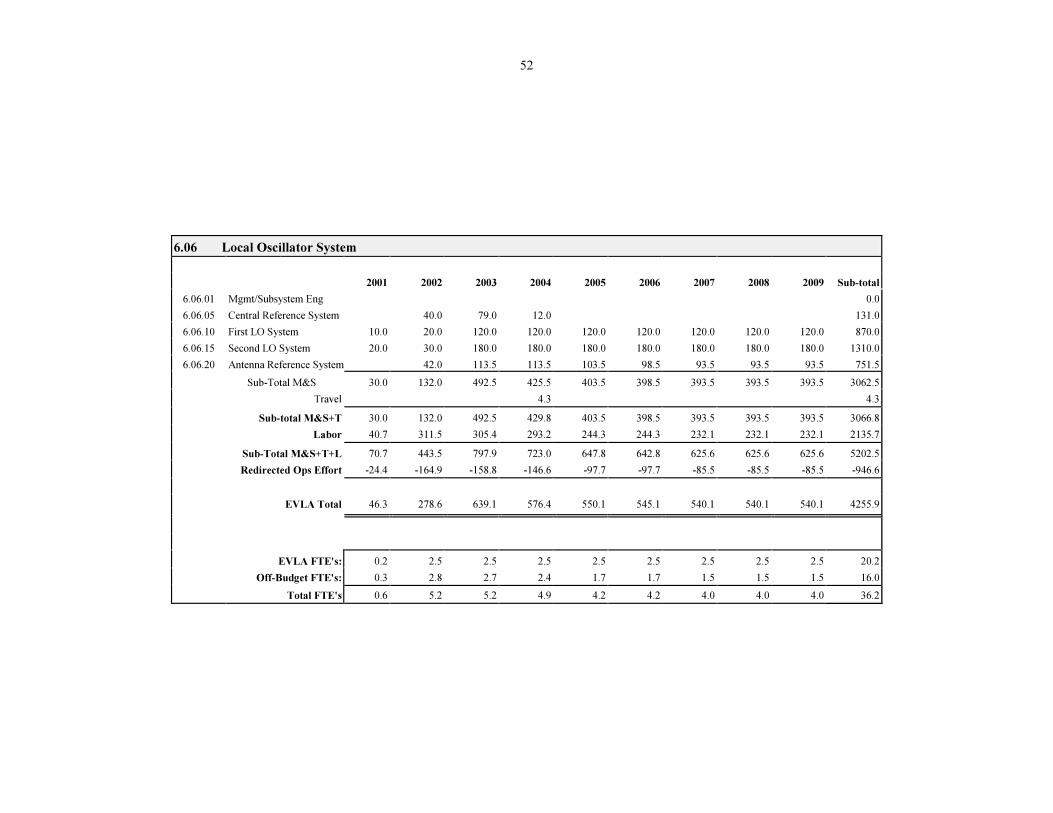
52
6.06 Local Oscillator System
2001
2002
2003
2004
2005
2006
2007
2008
2009
Sub-total
6.06.01
Mgmt/Subsystem Eng
0.0
6.06.05
Central Reference System
40.0
79.0
12.0
131.0
6.06.10
First LO System
10.0
20.0
120.0
120.0
120.0
120.0
120.0
120.0
120.0
870.0
6.06.15
Second LO System
20.0
30.0
180.0
180.0
180.0
180.0
180.0
180.0
180.0
1310.0
6.06.20
Antenna Reference System
42.0
113.5
113.5
103.5
98.5
93.5
93.5
93.5
751.5
Sub-Total M&S
30.0
132.0
492.5
425.5
403.5
398.5
393.5
393.5
393.5
3062.5
Travel
4.3
4.3
Sub-total M&S+T
30.0
132.0
492.5
429.8
403.5
398.5
393.5
393.5
393.5
3066.8
Labor
40.7
311.5
305.4
293.2
244.3
244.3
232.1
232.1
232.1
2135.7
Sub-Total M&S+T+L
70.7
443.5
797.9
723.0
647.8
642.8
625.6
625.6
625.6
5202.5
Redirected Ops Effort
-24.4
-164.9
-158.8
-146.6
-97.7
-97.7
-85.5
-85.5
-85.5
-946.6
EVLA Total
46.3
278.6
639.1
576.4
550.1
545.1
540.1
540.1
540.1
4255.9
EVLA FTE's:
0.2
2.5
2.5
2.5
2.5
2.5
2.5
2.5
2.5
20.2
Off-Budget FTE's:
0.3
2.8
2.7
2.4
1.7
1.7
1.5
1.5
1.5
16.0
Total FTE's
0.6
5.2
5.2
4.9
4.2
4.2
4.0
4.0
4.0
36.2
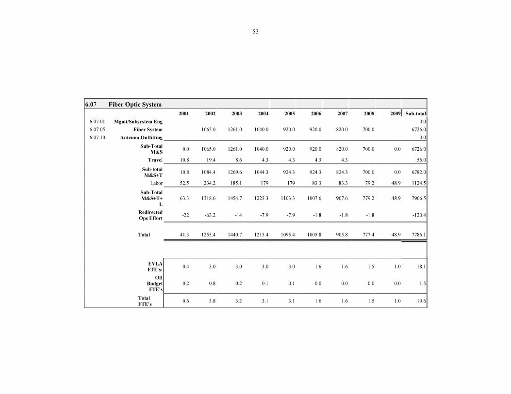
53
6.07 Fiber Optic System
2001
2002
2003
2004
2005
2006
2007
2008
2009
Sub-total
6.07.01
Mgmt/Subsystem Eng
0.0
6.07.05
Fiber System
1065.0
1261.0
1040.0
920.0
920.0
820.0
700.0
6726.0
6.07.10
Antenna Outfitting
0.0
Sub-Total
M&S
0.0
1065.0
1261.0
1040.0
920.0
920.0
820.0
700.0
0.0
6726.0
Travel
10.8
19.4
8.6
4.3
4.3
4.3
4.3
56.0
Sub-total
M&S+T
10.8
1084.4
1269.6
1044.3
924.3
924.3
824.3
700.0
0.0
6782.0
Labor
52.5
234.2
185.1
179
179
83.3
83.3
79.2
48.9
1124.5
Sub-Total
M&S+T+L
63.3
1318.6
1454.7
1223.3
1103.3
1007.6
907.6
779.2
48.9
7906.5
Redirected
Ops Effort
-22
-63.2
-14
-7.9
-7.9
-1.8
-1.8
-1.8
-120.4
Total
41.3
1255.4
1440.7
1215.4
1095.4
1005.8
905.8
777.4
48.9
7786.1
EVLA
FTE's:
0.4
3.0
3.0
3.0
3.0
1.6
1.6
1.5
1.0
18.1
Off
Budget FTE's
0.2
0.8
0.2
0.1
0.1
0.0
0.0
0.0
0.0
1.5
Total
FTE's
0.6
3.8
3.2
3.1
3.1
1.6
1.6
1.5
1.0
19.6

54
6.08 Intermediate Frequency System
2001
2002
2003
2004
2005
2006
2007
2008
2009
Sub-total
6.08.01
Mgmt/Subsystem Eng
20.0
20.0
40.0
6.08.05
Band Switches
429.0
380.0
380.0
380.0
380.0
380.0
380.0
380.0
3089.0
6.08.10
Samplers
20.0
94.0
161.0
161.0
161.0
161.0
161.0
161.0
1080.0
6.08.15
Transition Hardware
25.0
25.0
45.0
45.0
45.0
45.0
45.0
45.0
320.0
Sub-Total M&S
20.0
494.0
499.0
586.0
586.0
586.0
586.0
586.0
586.0
4529.0
Travel
0.0
Sub-total M&S+T
20.0
494.0
499.0
586.0
586.0
586.0
586.0
586.0
586.0
4529.0
Labor
6.1
262.7
283.0
307.4
264.7
264.7
264.7
264.7
264.7
2182.7
Sub-Total M&S+T+L
26.1
756.7
782.0
893.4
850.7
850.7
850.7
850.7
850.7
6711.7
Redirected Ops Effort
-6.1
-42.8
-63.1
-87.6
-93.7
-93.7
-93.7
-93.7
-93.7
-668.1
Total
20.0
713.9
718.9
805.8
757.0
757.0
757.0
757.0
757.0
6043.6
Total EVLA FTE's:
0.0
4.0
4.0
4.0
3.0
3.0
3.0
3.0
3.0
27.0
Total Off-Budget FTE's:
0.1
0.7
1.1
1.3
1.4
1.4
1.4
1.4
1.4
10.2
Total FTE's
0.1
4.7
5.1
5.3
4.4
4.4
4.4
4.4
4.4
37.2

55
6.09 Correlator
2001
2002
2003
2004
2005
2006
2007
2008
2009 Sub-total
6.09.01
Mgmt/Subsystem Eng
25.0
70.0
30
150.0
30.0
30.0
30.0
15.0
380.0
6.09.05
NRAO Correlator
Interface
0.0
0.0
0.0
0.0
0.0
0.0
0.0
0.0
0.0
0.0
6.09.10
Pre Project Tooling Setup
124.0
167.0
0.0
0.0
0.0
0.0
0.0
0.0
0.0
291.0
6.09.15
Station Board
0.0
0.0
0.0
122.0
0.0
1830.0
0.0
0.0
0.0
1952.0
6.09.20
Sub-Band Distributor
Backplane
0.0
0.0
0.0
4.0
0.0
12.0
0.0
0.0
0.0
16.0
6.09.25
Station Data Fanout Board
0.0
0.0
0.0
3.5
0.0
290.0
0.0
0.0
0.0
293.5
6.09.30
Baseline Entry Backplane
0.0
0.0
0.0
4.0
0.0
33.0
0.0
0.0
0.0
37.0
6.09.35
Baseline Board
0.0
125.0
125.0
287.0
0.0
2000.0
0.0
0.0
0.0
2537.0
6.09.40
Phasing Board
0.0
0.0
0.0
22.0
0.0
70.0
0.0
0.0
0.0
92.0
6.09.45
Phasing Board Entry
Backplane
0.0
0.0
0.0
1.0
0.0
3.5
0.0
0.0
0.0
4.5
6.09.50
TIMECODE Generator
Box
0.0
0.0
0.0
4.5
0.0
4.0
0.0
0.0
0.0
8.5
6.09.55
Real-time S/W
development
0.0
0.0
0.0
0.0
0.0
0.0
0.0
0.0
0.0
0.0
6.09.60
System Design (racks,
power, cabling,
computing)
0.0
0.0
0.0
20.0
0.0
0.0
0.0
0.0
0.0
20.0
6.09.65
Production model
test/burn-in
0.0
0.0
0.0
0.0
0.0
0.0
0.0
0.0
0.0
0.0
6.09.70
System Integration + Test
---Penticton
0.0
0.0
0.0
0.0
0.0
0.0
0.0
0.0
0.0
0.0
6.09.75
System Integration + Test
---VLA off-line
0.0
0.0
0.0
0.0
4.0
0.0
1849.0
30.0
17.0
1900.0
6.09.80
On-line debug, test --VLA
on -line
0.0
0.0
0.0
0.0
0.0
0.0
0.0
0.0
0.0
0.0
Sub-Total
M&S
149.0
362.0
155.0
618.0
34.0
4272.5
1879.0
45.0
17.0
7531.5
Travel
4.3
4.3
4.3
4.3
4.3
21.5
Sub-total M&S+T
149.0
366.3
159.3
622.3
38.3
4276.8
1879.0
45.0
17.0
7553.0
Labor
30.5
30.5
42.8
55.0
128.3
287.1
Sub-Total
M&S+T+L
149.0
396.8
189.8
665.1
93.3
4405.1
1879.0
45.0
17.0
7840.1
Redirected Ops Effort
-30.5
-30.5
-42.8
-55.0
-128.3
-287.1
Total
203.1
749.4
800.1
1112.7
506.4
4641.9
2502.9
365.7
152.9
11035.1
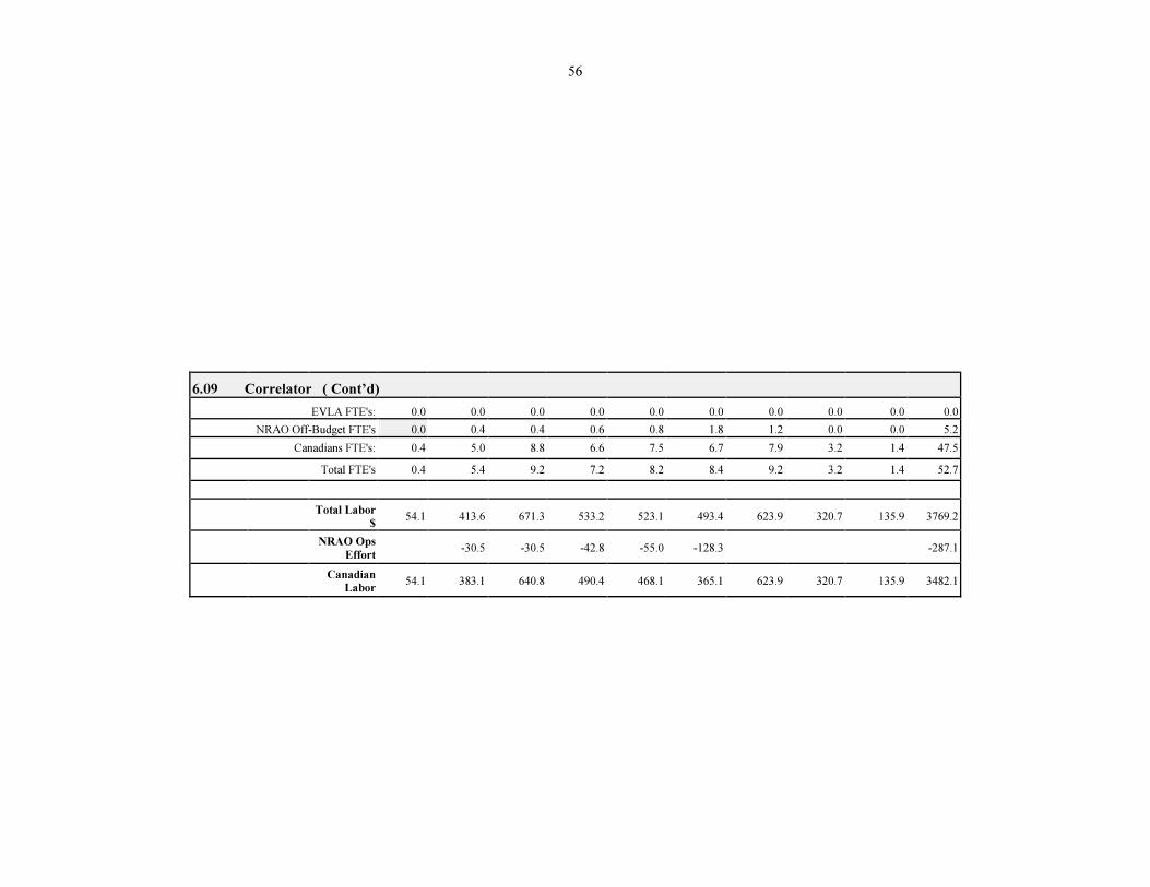
56
6.09 Correlator ( Cont’d)
EVLA FTE's: 0.0 0.0 0.0 0.0 0.0
0.0 0.0 0.0 0.0 0.0
NRAO Off-Budget FTE's
0.0
0.4
0.4
0.6
0.8
1.8
1.2
0.0
0.0
5.2
Canadians FTE's:
0.4
5.0
8.8
6.6
7.5
6.7
7.9
3.2
1.4
47.5
Total FTE's
0.4
5.4
9.2
7.2
8.2
8.4
9.2
3.2
1.4
52.7
Total Labor
$
54.1
413.6
671.3
533.2
523.1
493.4
623.9
320.7
135.9
3769.2
NRAO Ops
Effort
-30.5
-30.5
-42.8
-55.0
-128.3
-287.1
Canadian
Labor
54.1
383.1
640.8
490.4
468.1
365.1
623.9
320.7
135.9
3482.1
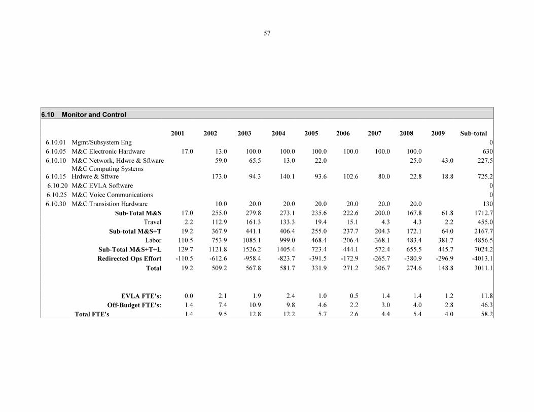
57
6.10 Monitor and Control
2001 2002 2003 2004 2005 2006 2007 2008 2009 Sub-total
6.10.01 Mgmt/Subsystem Eng 0
6.10.05 M&C Electronic Hardware 17.0 13.0 100.0 100.0 100.0 100.0 100.0 100.0 630
6.10.10 M&C Network, Hdwre & Sftware 59.0 65.5 13.0 22.0 25.0 43.0 227.5
6.10.15
M&C Computing Systems
Hrdwre & Sftwre 173.0 94.3 140.1 93.6 102.6 80.0 22.8 18.8 725.2
6.10.20 M&C EVLA Software 0
6.10.25 M&C Voice Communications 0
6.10.30 M&C Transistion Hardware 10.0 20.0 20.0 20.0 20.0 20.0 20.0 130
Sub-Total M&S 17.0 255.0 279.8 273.1 235.6 222.6 200.0 167.8 61.8 1712.7
Travel 2.2 112.9 161.3 133.3 19.4 15.1 4.3 4.3 2.2 455.0
Sub-total M&S+T 19.2 367.9 441.1 406.4 255.0 237.7 204.3 172.1 64.0 2167.7
Labor 110.5 753.9 1085.1 999.0 468.4 206.4 368.1 483.4 381.7 4856.5
Sub-Total M&S+T+L 129.7 1121.8 1526.2 1405.4 723.4 444.1 572.4 655.5 445.7 7024.2
Redirected Ops Effort -110.5 -612.6 -958.4 -823.7 -391.5 -172.9 -265.7 -380.9 -296.9 -4013.1
Total 19.2 509.2 567.8 581.7 331.9 271.2 306.7 274.6 148.8 3011.1
EVLA FTE's: 0.0 2.1 1.9 2.4 1.0 0.5 1.4 1.4 1.2 11.8
Off-Budget FTE's: 1.4 7.4 10.9 9.8 4.6 2.2 3.0 4.0 2.8 46.3
Total FTE's 1.4 9.5 12.8 12.2 5.7 2.6 4.4 5.4 4.0 58.2
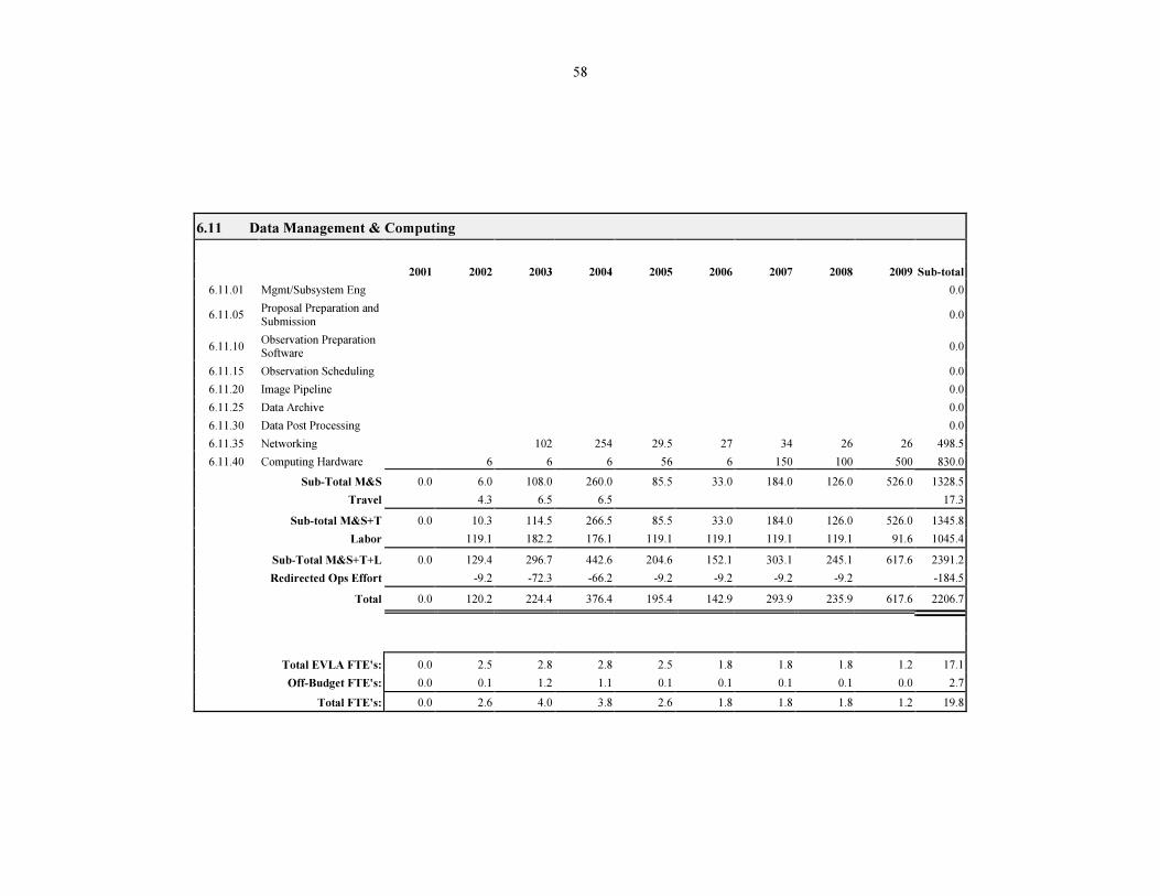
58
6.11 Data Management & Computing
2001
2002
2003
2004
2005
2006
2007
2008
2009
Sub-total
6.11.01
Mgmt/Subsystem Eng
0.0
6.11.05
Proposal Preparation and
Submission
0.0
6.11.10
Observation Preparation Software
0.0
6.11.15
Observation Scheduling
0.0
6.11.20
Image Pipeline
0.0
6.11.25
Data Archive
0.0
6.11.30
Data Post Processing
0.0
6.11.35
Networking
102
254
29.5
27
34
26
26
498.5
6.11.40
Computing Hardware
6
6
6
56
6
150
100
500
830.0
Sub-Total M&S
0.0
6.0
108.0
260.0
85.5
33.0
184.0
126.0
526.0
1328.5
Travel
4.3
6.5
6.5
17.3
Sub-total M&S+T
0.0
10.3
114.5
266.5
85.5
33.0
184.0
126.0
526.0
1345.8
Labor
119.1
182.2
176.1
119.1
119.1
119.1
119.1
91.6
1045.4
Sub-Total M&S+T+L
0.0
129.4
296.7
442.6
204.6
152.1
303.1
245.1
617.6
2391.2
Redirected Ops Effort
-9.2
-72.3
-66.2
-9.2
-9.2
-9.2
-9.2
-184.5
Total
0.0
120.2
224.4
376.4
195.4
142.9
293.9
235.9
617.6
2206.7
Total EVLA FTE's:
0.0
2.5
2.8
2.8
2.5
1.8
1.8
1.8
1.2
17.1
Off-Budget FTE's:
0.0
0.1
1.2
1.1
0.1
0.1
0.1
0.1
0.0
2.7
Total FTE's:
0.0
2.6
4.0
3.8
2.6
1.8
1.8
1.8
1.2
19.8
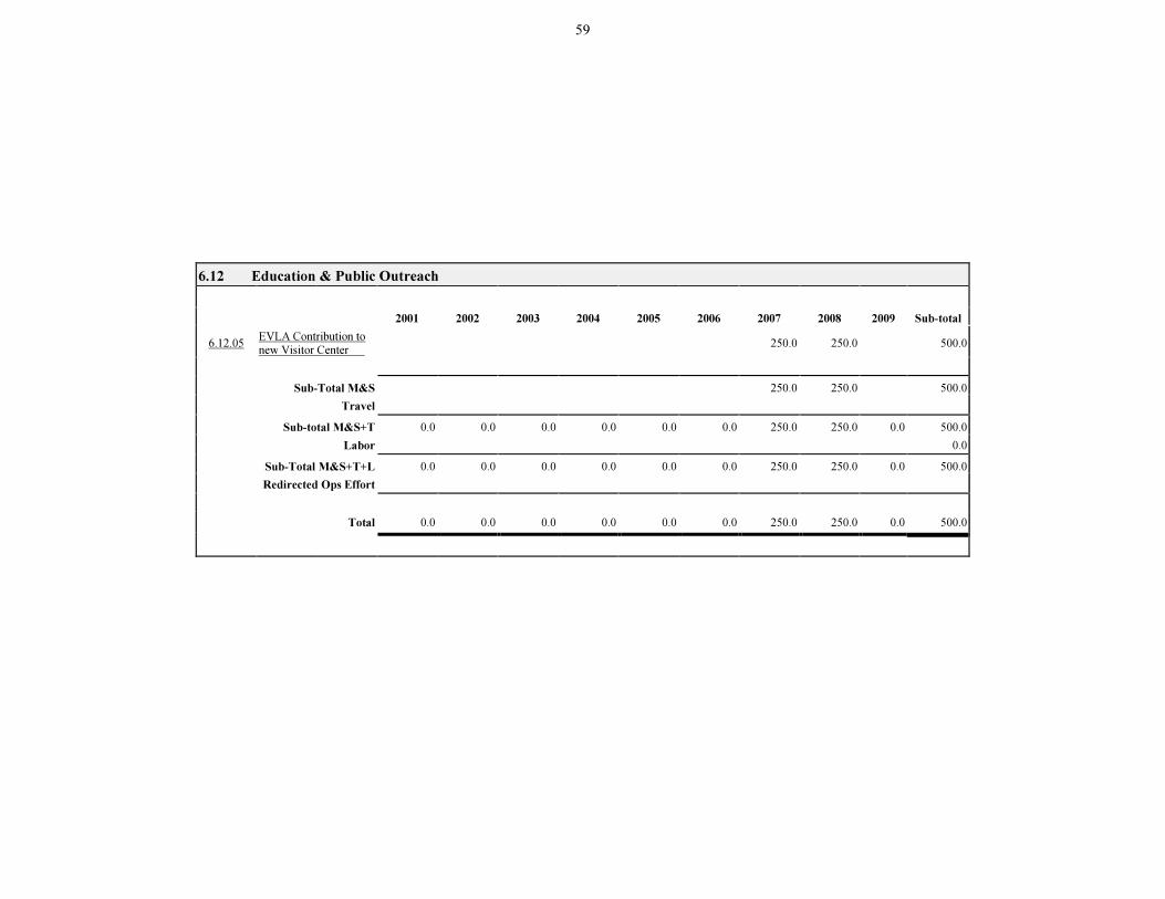
59
6.12 Education & Public Outreach
2001
2002
2003
2004
2005
2006
2007
2008
2009
Sub-total
6.12.05
EVLA Contribution to
new Visitor Center
250.0
250.0
500.0
Sub-Total M&S
250.0
250.0
500.0
Travel
Sub-total M&S+T
0.0
0.0
0.0
0.0
0.0
0.0
250.0
250.0
0.0
500.0
Labor
0.0
Sub-Total M&S+T+L
0.0
0.0
0.0
0.0
0.0
0.0
250.0
250.0
0.0
500.0
Redirected Ops Effort
Total
0.0
0.0
0.0
0.0
0.0
0.0
250.0
250.0
0.0
500.0


![Volte-Face (2001) [Vla]](https://img.pdfslide.net/doc/110x75/577cc1621a28aba71192d74b/volte-face-2001-vla.jpg)