Embed Size (px)
Citation preview
VLAN Fault Isolation User’s Guide
Document 9033543-02
Network Management
Titlepage

VLAN Fault Isolation User’s Guide Page 2
Copyright Notice
Document 9033543-02. Copyright © May 2000 Aprisma Management Technologies, Inc., 121 Technology Drive, Durham, NH 03824 USA. All rights reserved worldwide. Use, duplication, or disclosure by the United States government is subject to the restrictions set forth in DFARS 252.227-7013(c)(1)(ii) and FAR 52.227-19.
Liability Disclaimer
Aprisma Management Technologies, Inc. ("Aprisma") reserves the right to make changes in specifications and other information contained in this document without prior notice. In all cases, the reader should contact Aprisma to inquire if any changes have been made.
The hardware, firmware, or software described in this manual is subject to change without notice.
IN NO EVENT SHALL APRISMA, ITS EMPLOYEES, OFFICERS, DIRECTORS, AGENTS, OR AFFILIATES BE LIABLE FOR ANY INCIDENTAL, INDIRECT, SPECIAL, OR CONSEQUENTIAL DAMAGES WHATSOEVER (INCLUDING BUT NOT LIMITED TO LOST PROFITS) ARISING OUT OF OR RELATED TO THIS MANUAL OR THE INFORMATION CONTAINED IN IT, EVEN IF APRISMA HAS BEEN ADVISED OF, HAS KNOWN, OR SHOULD HAVE KNOWN, THE POSSIBILITY OF SUCH DAMAGES.
Trademark, Service Mark, and Logo Information
SPECTRUM, IMT, and the SPECTRUM IMT/VNM logo are registered trademarks of Aprisma Management Technologies, Inc., or its affiliates. APRISMA, APRISMA MANAGEMENT TECHNOLOGIES, the APRISMA MANAGEMENT TECHNOLOGIES logo, MANAGE WHAT MATTERS, DCM, VNM, SpectroGRAPH, SpectroSERVER, Inductive Modeling Technology, Device Communications Manager, SPECTRUM Security Manager, and Virtual Network Machine are unregistered trademarks of Aprisma Management Technologies, Inc., or its affiliates. For a complete list of Aprisma trademarks, service marks, and trade names, go tohttp://www.aprisma.com/manuals/trademark-list.htm.
All referenced trademarks, service marks, and trade names identified in this document, whether registered or unregistered, are the intellectual property of their respective owners. No rights are granted by Aprisma Management Technologies, Inc., to use such marks, whether by implication, estoppel, or otherwise. If you have comments or concerns about trademark or copyright references, please send an e-mail to [email protected]; we will do our best to help.
VLAN Fault Isolation User’s Guide Page 3
Restricted Rights Notice
(Applicable to licenses to the United States government only.)
This software and/or user documentation is/are provided with RESTRICTED AND LIMITED RIGHTS. Use, duplication, or disclosure by the government is subject to restrictions as set forth in FAR 52.227-14 (June 1987) Alternate III (g)(3) (June 1987), FAR 52.227-19 (June 1987), or DFARS 52.227-7013 (c)(1)(ii) (June 1988), and/or in similar or successor clauses in the FAR or DFARS, or in the DOD or NASA FAR Supplement, as applicable. Contractor/manufacturer is Aprisma Management Technologies, Inc., 121 Technology Drive, Durham, NH 03824. In the event the government seeks to obtain the software pursuant to standard commercial practice, this software agreement, instead of the noted regulatory clauses, shall control the terms of the government's license.
Virus Disclaimer
Aprisma makes no representations or warranties to the effect that the licensed software is virus-free.
Aprisma has tested its software with current virus-checking technologies. However, because no anti-virus system is 100 percent effective, we strongly recommend that you write-protect the licensed software and verify (with an anti-virus system in which you have confidence) that the licensed software, prior to installation, is virus-free.
Contact Information
Aprisma Management Technologies, Inc.
121 Technology Drive
Durham, NH 03824
Phone: 603.334.2100
U.S. toll-free: 877.468.1448
Web site: http://www.aprisma.com
VLAN Fault Isolation Page 4
ContentsPreface 6
Introduction 9
VLAN Overview ............................................................................................................9Types of VLANs ......................................................................................................10Benefits of VLANs ..................................................................................................11
SPECTRUM and VLANs ............................................................................................12Beyond the Bounds of Standards ...........................................................................13Device Discovery ....................................................................................................13Dynamic Adaptive Modeling ...................................................................................13VLAN Fault Isolation ...............................................................................................14Alarms in VLAN Domains .......................................................................................15
VLAN Fault Isolation Views ........................................................................................15The VLAN Fault Isolation Topology View ...............................................................16The VLAN List View ................................................................................................17
Using VLAN Fault Isolation 20
Preparing to Use VLAN Fault Isolation ......................................................................20Model VLAN Domain(s) ..........................................................................................20
AutoDiscovery .....................................................................................................20Manual Modeling .................................................................................................20
Manually Editing Topology Views ...........................................................................21Isolating VLAN Faults .................................................................................................22Using the VLAN List View ..........................................................................................22
User View ...............................................................................................................22Port View ................................................................................................................24Options ...................................................................................................................25
Specifying the SPECTRUM VLAN Modeling Configuration Interval ...................26Reading Switch Tables Immediately ...................................................................27
Using the VLAN Find Feature .................................................................................27
Theory of Operations 28
VLAN Fault Isolation Operations ................................................................................28
Contents Contents
VLAN Fault Isolation Page 5
VLAN Terminology 30
Index 40
VLAN Fault Isolation Page 6
Preface
This preface provides an introduction to the SPECTRUM VLAN Fault Isolation documentation, discusses who should read this guide, describes how the guide is organized, and provides information about viewing and printing this document.
Welcome to the SPECTRUM VLAN Fault Isolation User’s Guide. This book is a guide to using SPECTRUM VLAN Fault Isolation. It provides an overview of VLAN Fault Isolation, provides instructions on how to use VLAN Fault isolation, describes how VLAN Fault Isolation works, and includes a glossary of VLAN related terms.
Who Should Read This GuideThis guide is intended for use by network administrators and technicians responsible for day-to-day administration of a network.
This guide presumes you are familiar with the terms and principles associated with traditional network devices such as hubs, routers, and bridges, the terms and principles associated with VLAN networks, as well as with the terms and principles associated with SPECTRUM. It also presumes that you are familiar with traditional networking models and standards,(i.e., the Open Systems Interconnection (OSI) model, and the 802.1d, 802.3, and 802.5 standards).
This manual is written from a Motif windowing environment perspective. If you are using another interface (i.e. OpenLook), screens and mouse functionality will vary according to the interface being used.
Tip:Tip:If you have Motif and Open Windows installed on your system, you can switch between windowing systems using the OIT_LOOK <environment variable>. Windowing environment variables are: MOTIF or OPENWIN. The command used for the csh is setenv OIT_LOOK <environment variable>. The command for the ksh is export OIT_LOOK=<environment variable>.
Preface
VLAN Fault Isolation Page 7
Using This ManualThis manual is divided into four sections:
Introduction - This section provides an overview of VLANs and their benefits, describes how SPECTRUM supports VLANs, and discusses VLAN Fault Isolation concepts and views.
Using VLAN Fault Isolation - This section provides task oriented information which is required to successfully use VLAN Fault Isolation.
Theory of Operations - This section provides information about how VLAN Fault isolation works and how it is integrated into existing SPECTRUM functionality.
VLAN Terminology - This section defines the VLAN terms used in this guide as well as other common VLAN terms.
Viewing and Printing this DocumentTo view and print the SPECTRUM VLAN Fault Isolation User’s Guide, you need the Adobe™ Acrobat™ Reader. With Adobe Acrobat Reader on your system, you can access this guide:
From the docs directory on the CD-ROM by starting up Adobe Acrobat Reader and selecting File ? Open from the menu.
From the SPECTRUM Help menu, since this guide is installed as an integral part of SPECTRUM. This document is also available in PDF format on Aprisma’s Virtual Networking web site at http://www.aprisma.com/manuals/.
Preface
VLAN Fault Isolation Page 8
Related Documentation
Cisco VLAN Director User’s Guide
Getting Started with SPECTRUM for Administrators
Modeling with the GnSNMPDev Toolkit
AutoDiscovery User’s Guide
Questions about SPECTRUM Documentation
Send your questions, comments or suggestions regarding SPECTRUM documentation to the Technical Communications Department directly via the following internet address:
Note:Note:
You can access all related documentation listed in this section with the exception of the Cisco VLAN Director User’s Guide at http://www.aprisma.com/manuals/.
VLAN Fault Isolation Page 9
Introduction
This section provides an overview of VLANs and their benefits, describes how SPECTRUM supports VLANs, and discusses VLAN Fault Isolation concepts and views.
VLAN OverviewNormally, bridges and switches do not filter LAN broadcast traffic; in general, they replicate it on all ports. Virtual LAN (VLAN) enabled switches segment the network into logically defined work groups. Broadcast traffic from servers and end-stations in a particular VLAN is replicated only on those ports connected to end-stations belonging to that VLAN. Broadcast traffic is blocked from ports with no end-points belonging to that VLAN, creating the same type of broadcast containment that routers provide.
A Virtual LAN is a logical Layer 2 broadcast domain. It is a logical segmentation of the network, whereas bridges and switches provide a physical segmentation of the network.
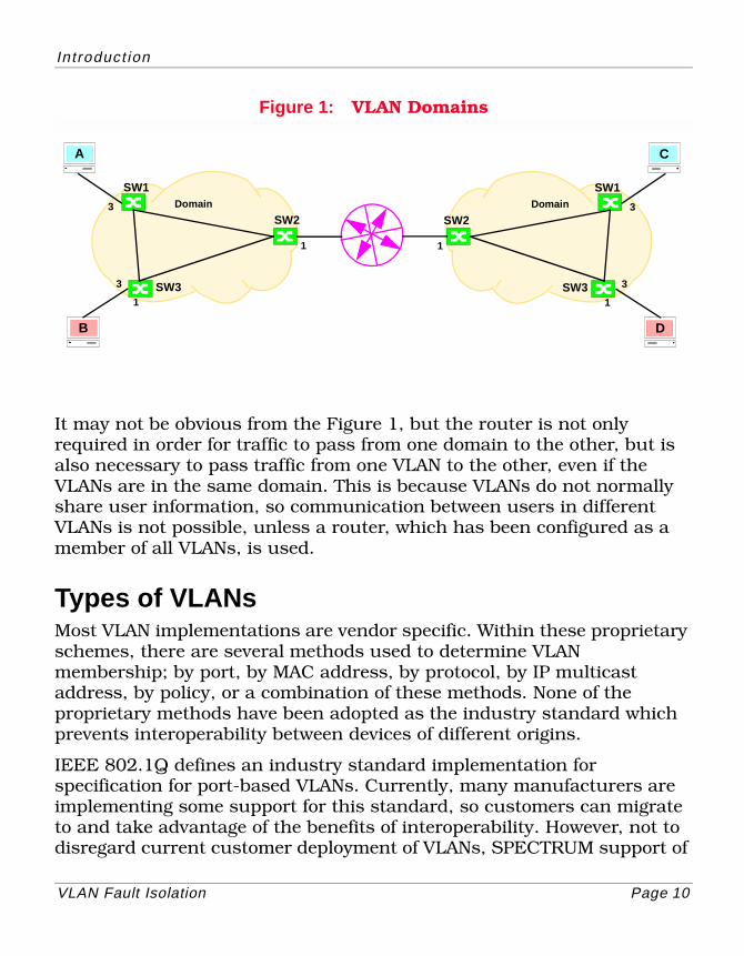
Figure 1 shows two VLAN domains connected by a router. Two VLANs are also shown. The Red VLAN consists of workstations B and D. The Blue VLAN contains workstations A and C as well as the SpectroSERVER.
In troduct ion
VLAN Fault Isolation Page 10
Figure 1: VLAN Domains
It may not be obvious from the Figure 1, but the router is not only required in order for traffic to pass from one domain to the other, but is also necessary to pass traffic from one VLAN to the other, even if the VLANs are in the same domain. This is because VLANs do not normally share user information, so communication between users in different VLANs is not possible, unless a router, which has been configured as a member of all VLANs, is used.
Types of VLANsMost VLAN implementations are vendor specific. Within these proprietary schemes, there are several methods used to determine VLAN membership; by port, by MAC address, by protocol, by IP multicast address, by policy, or a combination of these methods. None of the proprietary methods have been adopted as the industry standard which prevents interoperability between devices of different origins.
IEEE 802.1Q defines an industry standard implementation for specification for port-based VLANs. Currently, many manufacturers are implementing some support for this standard, so customers can migrate to and take advantage of the benefits of interoperability. However, not to disregard current customer deployment of VLANs, SPECTRUM support of
A
SFS Network
B
SW1
SW2
SW3
1
1
3
3
Domain
C
SFS Network
D
SW1
SW2
SW3
1
1
3
3
Domain
In troduct ion
VLAN Fault Isolation Page 11
VLANs includes standard IEEE 802.1Q, Cisco ISL, and Cabletron SecureFast.
Benefits of VLANsVLANs simplify the process of adds, moves, and changes that result when caused by end users moving from one place on the network to another place on the network. These types of changes require reconfiguring a user’s workstation and often involve a trip to the wiring closet. Tools have been developed to assist administrators in configuring and deploying VLANs across the entire switching fabric reducing the cost of handling user moves, and allowing for a more dynamic workgroup-based organizational environment by removing most of the physical constraints associated with network user moves.
VLANs allow an administrator to strategically control the amount of broadcast and multicast traffic on the switched fabric. This enables a higher level of performance and scaleability over traditional bridged and routed networks. VLAN membership is extremely dynamic and flexible further enhancing an administrators control over the network. An end-station can belong to multiple VLANs.
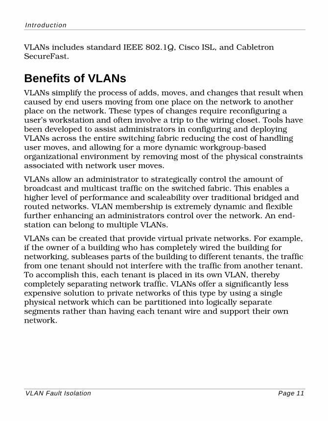
VLANs can be created that provide virtual private networks. For example, if the owner of a building who has completely wired the building for networking, subleases parts of the building to different tenants, the traffic from one tenant should not interfere with the traffic from another tenant. To accomplish this, each tenant is placed in its own VLAN, thereby completely separating network traffic. VLANs offer a significantly less expensive solution to private networks of this type by using a single physical network which can be partitioned into logically separate segments rather than having each tenant wire and support their own network.
In troduct ionSPECTRUM and VLANs
VLAN Fault Isolation Page 12
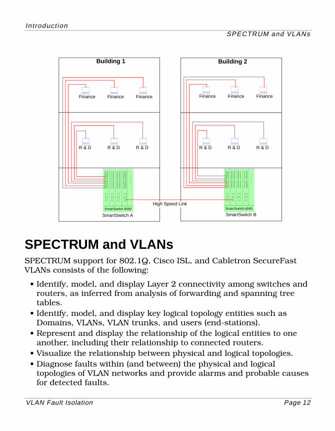
SPECTRUM and VLANsSPECTRUM support for 802.1Q, Cisco ISL, and Cabletron SecureFast VLANs consists of the following:
• Identify, model, and display Layer 2 connectivity among switches and routers, as inferred from analysis of forwarding and spanning tree tables.
• Identify, model, and display key logical topology entities such as Domains, VLANs, VLAN trunks, and users (end-stations).
• Represent and display the relationship of the logical entities to one another, including their relationship to connected routers.
• Visualize the relationship between physical and logical topologies.• Diagnose faults within (and between) the physical and logical
topologies of VLAN networks and provide alarms and probable causes for detected faults.
Building 1
Finance
Building 2
SmartSwitch 6000 SmartSwitch 6000
Finance Finance
R & D R & D R & D
Finance Finance Finance
R & D R & D R & D
SmartSwitch A SmartSwitch B
High Speed Link
In troduct ionSPECTRUM and VLANs
VLAN Fault Isolation Page 13
• Minimize the number of false alarms generated.
Beyond the Bounds of StandardsSPECTRUM modeling mainly relies on the content of switch forwarding tables to determine VLAN membership. SPECTRUM does not rely on any rules governing the entry method into the forwarding tables, the creation and definition of VLANs may be vendor specific.
Device DiscoverySPECTRUM’s AutoDiscovery process will map the port-to-port connectivity of VLAN switches, including the connectivity of VLAN switch ports to routers and workstations. First, AutoDiscovery interrogates all of the IP addresses specified by the user, and creates models to represent the devices found. To map the connectivity, AutoDiscovery reads information from IETF standard MIBs (i.e. the dot1dBridge MIB) including information from the spanning tree table and the forwarding database. Depending on device support and the management modules installed, AutoDiscovery will also query enterprise “discovery protocol” and “source address” MIBs. The supported enterprise MIBs include the Cisco Discovery Protocol MIB, the Extreme Discovery Protocol MIB, and Cabletron Discovery Protocol MIB.
Once the environment has been fully scanned, a complete physical topology will be modeled and mapped. If AutoDiscovery does not create a complete map of the physical (port-to-port) connectivity, you must complete the map by manually modeling the connections or devices that are missing. VLAN topology overlay and VLAN fault isolation will not work properly if all devices and connections are not mapped. For information on manual modeling and resolving port connections, refer to the How to Manage Your Network with SPECTRUM guide.
Dynamic Adaptive ModelingSPECTRUM has the ability to query devices to understand the type of services they support. Since this technology is a core SPECTRUM feature,
In troduct ionSPECTRUM and VLANs
VLAN Fault Isolation Page 14
it does not rely on the presence of a specific management module. Even if a device is modeled using the default SNMP Device Model, the functionality required to understand the services supported by the device still applies.
During the modeling process, device models are created for switches and routers that support 802.1Q, Cisco ISL, or Cabletron SecureFast VLANs. DAM then creates application models for each device depending on the protocol the device is running and the MIBs containing VLAN information for the device. Other SPECTRUM inference handlers will identify, model (or associate), and display the:
• Entities that represent Domains and VLANs• Ports that belong to each VLAN.• Blocked switch ports that result from the Spanning Tree algorithm.• Routers, switches, and links that connect the VLANs and Domains
together.• End-stations that are members of each VLAN.• Trunk links that exist between switches.• Alarm condition on Domains, VLANs, links, switches, and routers.• The SpectroSERVER and the VLAN in which it resides.
VLAN Fault IsolationSPECTRUM VLAN Fault Isolation extends SPECTRUM’s fault isolation capability into VLAN environments. Without SPECTRUM VLAN Fault Isolation, SPECTRUM’s fault isolation intelligence relies strictly on physical connectivity to determine the data path from the SpectroSERVER to each managed device. When the SpectroSERVER fails to contact any device, that device’s physical neighbors are checked. If the neighbors can be contacted, SPECTRUM assumes the device to be at fault. If the neighbors cannot be contacted, SPECTRUM looks for a fault elsewhere.
In a VLAN environment, the management path cannot always be determined by physical connectivity between switches. In some cases, communication between two users on the same switch must traverse
In troduct ionVLAN Faul t Iso lat ion Views
VLAN Fault Isolation Page 15
several switches and a router. In these cases, a router configuration problem or a router hardware malfunction could prevent communication between the users, even though the users may be connected to different ports on the same switch. When a router failure is detected, SPECTRUM generates a Red (lost contact) alarm on the router model, and writes Gray (suppressed) to the condition value of affected user (end-station) models. You can display status, symptom, probable cause, and recommended action information associated with the alarm by clicking the Probable Cause tab while running Alarm Manager.
SPECTRUM VLAN Fault Isolation enhances SPECTRUM modeling to represent a logical VLAN topology, and adds intelligence that uses this modeling to pinpoint VLAN domain faults such as router failures.
Alarms in VLAN DomainsIn the VLAN views, the condition of the Domain, VLANs, switches, and routers follow the standard SPECTRUM roll-up idiom. For example, Domain and VLANs will be GREEN if all switches are green (i.e., all switches and end-stations are reachable from the SpectroSERVER). If the SpectroSERVER narrows the fault down to a router, VLANs and Domains that are not reachable, will be GRAY and no alarms will be generated for any of their switches or end-stations. On the other hand, if the routers are determined to be operating normally, further analysis will pinpoint the failing device(s). Core inference handlers provide the roll-up condition for VLAN and Domain containers.
VLAN Fault Isolation ViewsVLAN Fault Isolation views provide useful troubleshooting information so that you can quickly identify and resolve VLAN related problems.
Note:Note:
In order for these views to be accessible, the value of the ENABLE_VLAN_CONFIG parameter in the .vnmrc file must be set to TRUE (Page 20).
In troduct ionVLAN Faul t Iso lat ion Views
VLAN Fault Isolation Page 16
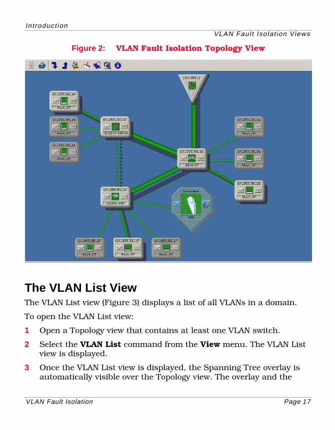
The VLAN Fault Isolation Topology ViewThe VLAN Fault Isolation Topology View (Figure 2) provides accurate logical topology representations of VLAN domains within a network and identifies faulty domain devices. This view contains the standard SPECTRUM topology view components, as well as an overlay containing Spanning Tree information. The Spanning Tree overlay highlights the VLAN device models and the pipes between those models, showing trunk connections between switches.
Spanning Tree prevents looping on the network so if redundant paths exist between switches, Spanning Tree designates one path as the primary path and the other path as the backup path. In the VLAN Fault Isolation Topology view, the primary path between two switches is shown with solid, bold pipes. The backup path between two switches depicting a blocked port in Spanning Tree is shown with a dashed line.
In order to access this view, you must:
1 Open a Topology view that contains at least one VLAN switch.
2 Select the VLAN List command from the View menu. The VLAN List view is displayed (Page 17).
3 Once the VLAN List view is displayed, the Spanning Tree overlay is automatically visible over the Topology view. The overlay and the Topology view combined make up VLAN Fault Isolation Topology view.
In troduct ionVLAN Faul t Iso lat ion Views
VLAN Fault Isolation Page 17
Figure 2: VLAN Fault Isolation Topology View
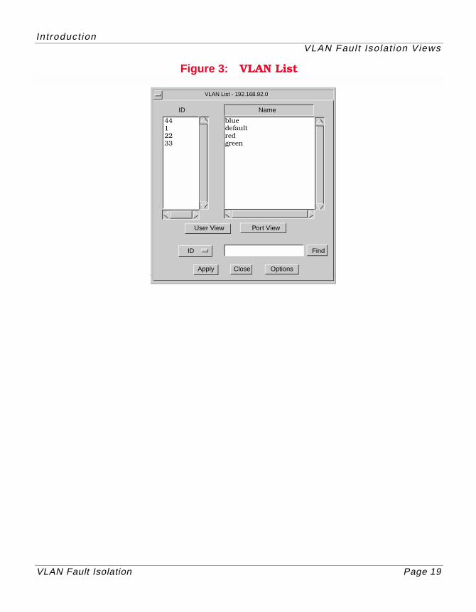
The VLAN List ViewThe VLAN List view (Figure 3) displays a list of all VLANs in a domain.
To open the VLAN List view:
1 Open a Topology view that contains at least one VLAN switch.
2 Select the VLAN List command from the View menu. The VLAN List view is displayed.
3 Once the VLAN List view is displayed, the Spanning Tree overlay is automatically visible over the Topology view. The overlay and the
In troduct ionVLAN Faul t Iso lat ion Views
VLAN Fault Isolation Page 18
Topology view combined make up VLAN Fault Isolation Topology view. (Page 16).
The VLAN List view provides access to additional views and functions as described below.
• User View - Provides information about the users with membership in the selected VLAN. Refer to User View.
• Port View - Provides information about ports with membership in the selected VLAN. Traffic can only be forwarded out ports with membership in a VLAN. Refer to Port View.
• Options - Lets you specify how frequently SPECTRUM will read the switch tables in order to determine port VLAN membership and to specify the path to your VLAN configuration tool. Refer to Options.
• ID/Find - Lets you search for a particular VLAN by VLAN ID or VLAN name. Refer to Using the VLAN Find Feature.
• Apply - Applies the selected VLAN topology overlay (some VLAN technologies offer multiple spanning trees).
• Close - Dismisses the VLAN List View and removes Spanning Tree overlays from the VLAN Topology View.
In troduct ionVLAN Faul t Iso lat ion Views
VLAN Fault Isolation Page 19
Figure 3: VLAN List
VLAN List - 192.168.92.0
ID Name
User View Port View
ID
Apply Close Options
Find
4412233
bluedefaultredgreen
VLAN Fault Isolation Page 20
Using VLAN Fault Isolation
This section provides task oriented information which is required to successfully use VLAN Fault Isolation.
Preparing to Use VLAN Fault IsolationBefore using VLAN Fault Isolation, you must change the VLAN setting in SPECTRUM .vnmrc resource file. By default, the enable_vlan_config parameter is set to FALSE. In order to properly set up a VLAN, change this setting to TRUE. For more information on the .vnmrc file and how to make changes in this file, see the Defining SPECTRUM’s Resources manual.
After making this change, you must set up your VLAN domain and model the devices contained in the domain. Each VLAN domain setup is unique and depends on the network where it is deployed. However, SPECTRUM expects each VLAN domain to contain a set of VLAN aware switches bounded by a routing device such as a router.
Model VLAN Domain(s)There are two methods you can use to create models for devices in a VLAN domain, using AutoDiscovery to model the devices and manually modeling the devices.
AutoDiscoveryYou can use SPECTRUM’s AutoDiscovery feature to create models for the devices in a VLAN domain.
Manual ModelingIf you prefer, you can manually create models for the devices in a VLAN domain manually by selecting Edit > New Model or Edit > New Model by IP while in edit mode.
Using VLAN Faul t Iso lat ionPrepar ing to Use VLAN Faul t Isolat ion
VLAN Fault Isolation Page 21
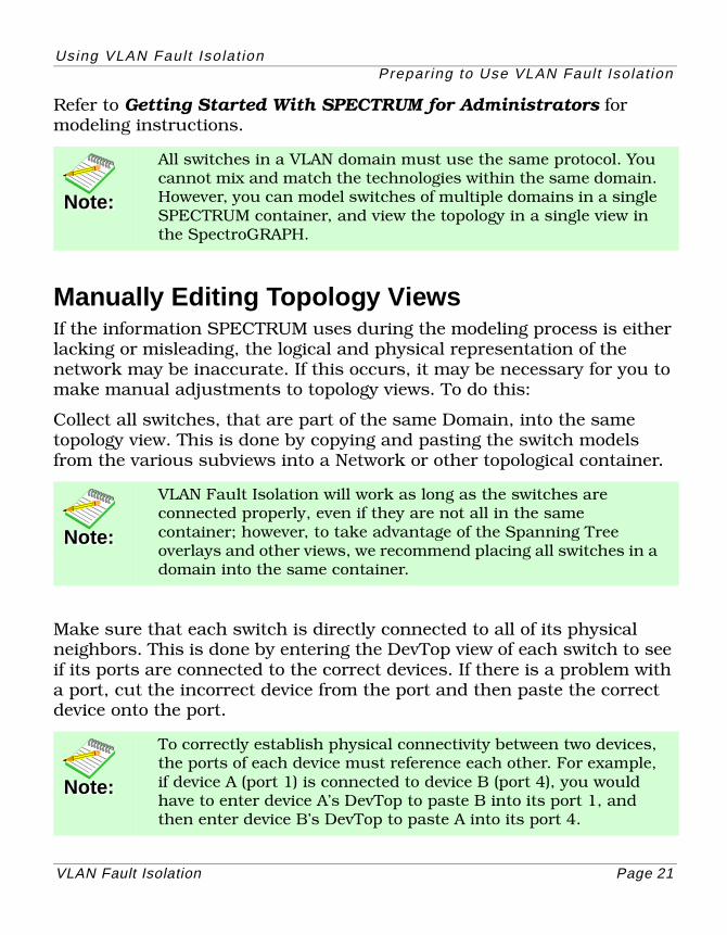
Refer to Getting Started With SPECTRUM for Administrators for modeling instructions.
Manually Editing Topology ViewsIf the information SPECTRUM uses during the modeling process is either lacking or misleading, the logical and physical representation of the network may be inaccurate. If this occurs, it may be necessary for you to make manual adjustments to topology views. To do this:
Collect all switches, that are part of the same Domain, into the same topology view. This is done by copying and pasting the switch models from the various subviews into a Network or other topological container.
Make sure that each switch is directly connected to all of its physical neighbors. This is done by entering the DevTop view of each switch to see if its ports are connected to the correct devices. If there is a problem with a port, cut the incorrect device from the port and then paste the correct device onto the port.
Note:Note:
All switches in a VLAN domain must use the same protocol. You cannot mix and match the technologies within the same domain. However, you can model switches of multiple domains in a single SPECTRUM container, and view the topology in a single view in the SpectroGRAPH.
Note:Note:
VLAN Fault Isolation will work as long as the switches are connected properly, even if they are not all in the same container; however, to take advantage of the Spanning Tree overlays and other views, we recommend placing all switches in a domain into the same container.
Note:Note:
To correctly establish physical connectivity between two devices, the ports of each device must reference each other. For example, if device A (port 1) is connected to device B (port 4), you would have to enter device A’s DevTop to paste B into its port 1, and then enter device B’s DevTop to paste A into its port 4.
Using VLAN Faul t Iso lat ionIsolat ing VLAN Faul ts
VLAN Fault Isolation Page 22
Isolating VLAN FaultsSPECTRUM automatically isolates VLAN faults. When a VLAN fault is detected, an alarm is generated on the failing device. You can display status, symptom, probable cause, and recommended action information associated with the alarm by clicking the Probable Cause tab while running Alarm Manager. Refer to the Enterprise Alarm Manager User’s Guide for more information.
Using the VLAN List ViewYou use the VLAN List View (Figure 3) to select a VLAN, to display the User and Port Views, and to set VLAN configuration options.
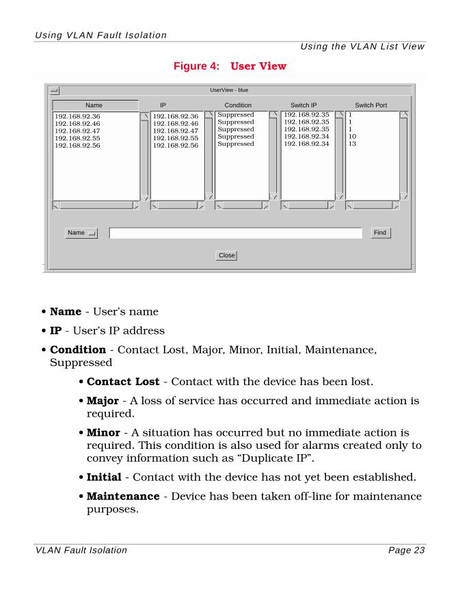
User ViewThe User View provides read-only Name, IP, Condition, Switch IP, and Switch Port information about the users in the selected VLAN. Users are endpoint devices modeled in SPECTRUM that are connected to a VLAN switch port.
To display the User View for a particular VLAN, select a VLAN from the VLAN list and then click User View. You can use the VLAN filter to quickly find a particular VLAN. Refer to Using the VLAN Find Feature. Close dismisses the User View.
Using VLAN Faul t Iso lat ionUsing the VLAN List View
VLAN Fault Isolation Page 23
Figure 4: User View
• Name - User’s name
• IP - User’s IP address
• Condition - Contact Lost, Major, Minor, Initial, Maintenance, Suppressed
• Contact Lost - Contact with the device has been lost.
• Major - A loss of service has occurred and immediate action is required.
• Minor - A situation has occurred but no immediate action is required. This condition is also used for alarms created only to convey information such as “Duplicate IP”.
• Initial - Contact with the device has not yet been established.
• Maintenance - Device has been taken off-line for maintenance purposes.
UserView - blue
IPName
Name
Close
Find
192.168.92.36192.168.92.46192.168.92.47192.168.92.55192.168.92.56
Condition
SuppressedSuppressedSuppressedSuppressedSuppressed
Switch IP
192.168.92.35192.168.92.35192.168.92.35192.168.92.34192.168.92.34
Switch Port
1111013
192.168.92.36192.168.92.46192.168.92.47192.168.92.55192.168.92.56
Using VLAN Faul t Iso lat ionUsing the VLAN List View
VLAN Fault Isolation Page 24
• Suppressed - Device cannot be reached due to a known error condition that exists on another device.
• Switch IP - Switch to which user is connected.
• Switch Port - Physical port to which the user is connected.
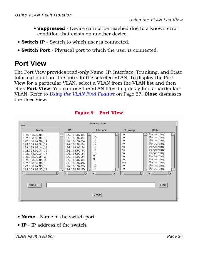
Port ViewThe Port View provides read-only Name, IP, Interface, Trunking, and State information about the ports in the selected VLAN. To display the Port View for a particular VLAN, select a VLAN from the VLAN list and then click Port View. You can use the VLAN filter to quickly find a particular VLAN. Refer to Using the VLAN Find Feature on Page 27. Close dismisses the User View.
Figure 5: Port View
• Name - Name of the switch port.
• IP - IP address of the switch.
PortView - blue
IPName
Name
Close
Find
192.168.92.34_1192.168.92.34_10192.168.92.34_11192.168.92.34_12192.168.92.34_13192.168.92.34_14192.168.92.34_15192.168.92.34_2192.168.92.34_9192.168.92.35_1192.168.92.35_13192.168.92.35_14
Interface
11011121314152911314
Trunking
nononononononononoyesnono
State
ForwardingForwardingForwardingForwardingForwardingForwardingForwardingForwardingForwardingForwardingForwardingForwarding
192.168.92.34192.168.92.34192.168.92.34192.168.92.34192.168.92.34192.168.92.34192.168.92.34192.168.92.34192.168.92.34192.168.92.35192.168.92.35192.168.92.35
Using VLAN Faul t Iso lat ionUsing the VLAN List View
VLAN Fault Isolation Page 25
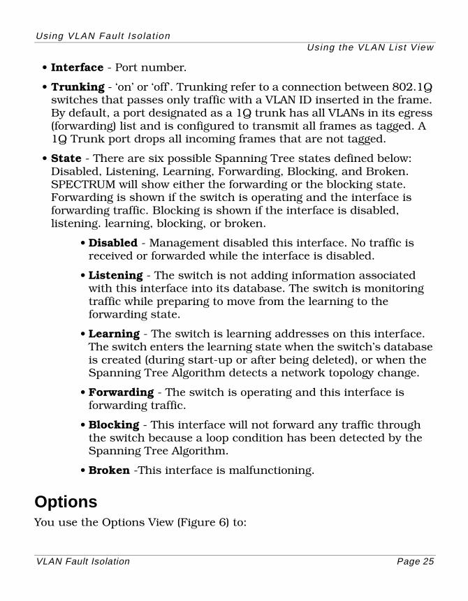
• Interface - Port number.
• Trunking - ‘on’ or ‘off’. Trunking refer to a connection between 802.1Q switches that passes only traffic with a VLAN ID inserted in the frame. By default, a port designated as a 1Q trunk has all VLANs in its egress (forwarding) list and is configured to transmit all frames as tagged. A 1Q Trunk port drops all incoming frames that are not tagged.
• State - There are six possible Spanning Tree states defined below: Disabled, Listening, Learning, Forwarding, Blocking, and Broken. SPECTRUM will show either the forwarding or the blocking state. Forwarding is shown if the switch is operating and the interface is forwarding traffic. Blocking is shown if the interface is disabled, listening. learning, blocking, or broken.
• Disabled - Management disabled this interface. No traffic is received or forwarded while the interface is disabled.
• Listening - The switch is not adding information associated with this interface into its database. The switch is monitoring traffic while preparing to move from the learning to the forwarding state.
• Learning - The switch is learning addresses on this interface. The switch enters the learning state when the switch’s database is created (during start-up or after being deleted), or when the Spanning Tree Algorithm detects a network topology change.
• Forwarding - The switch is operating and this interface is forwarding traffic.
• Blocking - This interface will not forward any traffic through the switch because a loop condition has been detected by the Spanning Tree Algorithm.
• Broken -This interface is malfunctioning.
OptionsYou use the Options View (Figure 6) to:
Using VLAN Faul t Iso lat ionUsing the VLAN List View
VLAN Fault Isolation Page 26
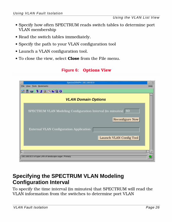
• Specify how often SPECTRUM reads switch tables to determine port VLAN membership
• Read the switch tables immediately.
• Specify the path to your VLAN configuration tool
• Launch a VLAN configuration tool.
• To close the view, select Close from the File menu.
Figure 6: Options View
Specifying the SPECTRUM VLAN Modeling Configuration IntervalTo specify the time interval (in minutes) that SPECTRUM will read the VLAN information from the switches to determine port VLAN
SpectroGRAPH: 192.168.92.0
192.168.92.0 of type LAN of landscape sugar: Primary
File View Tools Bookmarks Help
VLAN Domain Options
SPECTRUM VLAN Modeling Configuration Interval (in minutes)
External VLAN Configuration Application
60
Reconfigure Now
Launch VLAN Config Tool
Using VLAN Faul t Iso lat ionUsing the VLAN List View
VLAN Fault Isolation Page 27
membership, enter a value in the SPECTRUM VLAN Modeling Configuration Interval text field. The following values are recommended:
• 10 - 15 minutes for highly dynamic environments in which servers and/or workstations are modeled.
• 60 minutes for more static environments.
Reading Switch Tables ImmediatelyClick Reconfigure Now to immediately read the switch tables to determine current VLAN membership.
Using the VLAN Find FeatureUse the find feature to search for and find a particular VLAN. You can search by VLAN Name or VLAN ID.
To use the find feature:
1 Enter the name or the ID of the VLAN that you would like to search for.
2 Click the Find button.
3 The find feature will highlight the row in the list that matches the ID or the name (or partial name) that you have entered.
Note:Note:
A value of zero (0) means that no reading of the switch tables will take place.
VLAN Fault Isolation Page 28
Theory of Operations
This section provides information about how VLAN Fault isolation works and how it is integrated into existing SPECTRUM functionality.
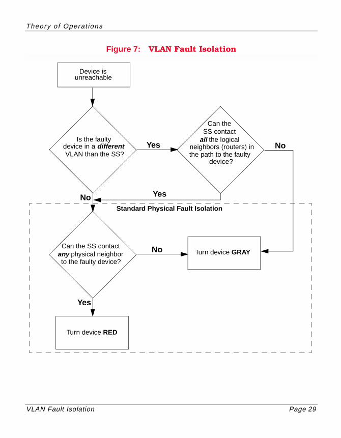
VLAN Fault Isolation OperationsThe flowchart shown in Figure 7 shows the process used by SPECTRUM to isolate VLAN faults. The following description may help to understand the process.
Once the VLAN membership of users (a user being a device model in SPECTRUM), has been fully modeled, SPECTRUM has the information necessary to fault isolate the VLAN environment. When the SpectroSERVER looses contact with a device, the first question that needs to be answered is “Is the device in the same VLAN as the SpectroSERVER?”
This can easily be answered by reading the vContains relation to see if the VNM model is associated with the same VLAN model as the device. This is done by querying the vLanContains relation twice, one with the VNM model (on the right side of the association), and then again with the device (on the right side of the association. If the VNM and the device are in the same VLAN, traditional SPECTRUM fault isolation is used. Otherwise, the logical neighbors of the lost device are queried.
The logical neighbors are found by reading the vlsBoundBy relation with the VLAN model of the device on the left. All router models that bound the VLAN are considered logical neighbors of all the VLAN’s members. These neighbors are queried by sending the model the ARE_YOU_DOWN action. If any of the neighbors respond “yes”, then the device icon is turned Gray. If all logical neighbors are up, traditional SPECTRUM fault isolation is used.
Theory of Operat ions
VLAN Fault Isolation Page 29
Figure 7: VLAN Fault Isolation
Can theSS contact
all the logicalneighbors (routers) inthe path to the faulty
device?
Device isunreachable
Is the faultydevice in a different VLAN than the SS?
Can the SS contactany physical neighborto the faulty device?
Turn device GRAY
Turn device RED
Standard Physical Fault Isolation
Yes
Yes
No
No
No
Yes
VLAN Fault Isolation Page 30
VLAN Terminology
This section contains definitions for commonly used VLAN Fault Isolation and VLAN (802.1Q, SecureFast, ISL) terms as well as definitions for other common network related terms.
1Q trunk
A connection between 802.1Q switches that passes only traffic with a VLAN Tag Header inserted in the frame.
1d trunk
A connection from a switch that passes only untagged traffic.
802.1Q
The IEEE standard that defines port based VLANs.
access port
A port on a VLAN switch that has been designated for user (end-system) connections.
alias
A way of identifying a user by something other than its MAC address, for example, by IP or IPX address.
Automatic Membership Registration (AMR)
A SecureFast VLAN Manager feature that dynamically creates VLANs, joins endpoints to those VLANs, and floods packets to those VLANs according to the set of criteria rules.
Base VLAN
VLAN that all endpoints in a domain have membership in until administratively moved to another VLAN.
VLAN Terminology
VLAN Fault Isolation Page 31
bindery
A database that contains a complete collection of related information.
broadcast
Data sent from one endpoint to all other network endpoints (point-to-multipoint communications).
community name - Defines security communities to which an SNMP agent is permitted access to a device and establishes Read/ReadWrite privileges.
Current Table (dot1qVlanCurrentTable)A map of VLAN IDs to a port egress list and a filtering database so that non-unicast and unicast packets can be forwarded appropriately.
default gateway - The switch port configured to service connection requests to subnets not serviced by the switches in a domain.
default VLAN
The VLAN assigned to be the default VLAN for a port. All endpoints connecting to a port will assume membership in the default VLAN for that port. For 802.1Q VLANs, the default VLAN has a VLAN ID of 1.
directory
A set of data about all users in a domain. Typically, the directory contains such entries as the user’s physical address, the switch and port to which the user is connected, and the network type, and the user’s name.
discover
Process used to find switches and users contained in a VLAN domain.
daemon
A software program that generally performs a single task and is executed only when it is needed.
VLAN Terminology
VLAN Fault Isolation Page 32
domainA set of VLAN switches that are physically connected together and bounded by a router. A domain identifies the potential physical reach of a VLAN. It also provides scope for the VLAN IDs.
Domain Name Server (DNS)
A protocol used to provide mappings between host names and IP addresses.
dynamic filtering entriesEntries that have been learned through correspondence with other switch devices via GVRP. After an agent restart, these entries will have to be relearned.
egress list (dot1qVlanCurrentEgressPorts)A per port list of all eligible 802.1Q VLANs that can be forwarded out one specific port and the frame format of transmissions for that port. The egress list specifies what 802.1Q VLANs are associated with a single port for transmission purposes.
endpoint
A device attached directly to a switch’s network user port (e.g., workstation, PC, or router).
filtering database (Filtering Identifier - FID)A table inside a switch that determines which ports unicast packets are forwarded to. The FID is similar to the Source Address table of a traditional bridge.
flooding
A method used by SecureFast switches so that, if the switch fails to resolve the destination address for a packet to a host or a VLAN, the packet is transmitted out all the switch’s ports except the port the packet was received on.
forwarding list
VLAN Terminology
VLAN Fault Isolation Page 33
A list of ports on a particular device that are eligible to transmit frames for a selected 802.1Q VLAN. The forwarding list identifies what ports are associated with a single 802.1Q VLAN for transmission purposes.
folder
A virtual container used to group users. There are two levels of folders. The first level groups different VLAN types (e.g., VLAN, AMR). The second level groups users of the same type (e.g., inherited, static).
Graphical User Interface (GUI)
An interface that allows a user to select a menu item by using a mouse to point to a graphic icon or piece of text. This is an alternative to the more traditional command line interface, where an alphanumeric string is used to convey instructions. GUIs make computer applications easier to use for humans (i.e., user friendly).
hub
The center of a star topology network or cabling system in which a multi-node network topology has a central multiplexor with many nodes feeding into and through the multiplexor or hub. The other nodes do not usually directly interconnect.
Independent VLAN Learning (IVL)The configuration and operation of the learning process and the filtering database such that, for a given set of VLANs, if a given individual MAC address is learnt in one VLAN, that learnt information is not used in forwarding decisions taken for that address relative to any other VLAN in the given set.
Internet Protocol (IP)
One of a collection of communication protocols which has become the de facto solution for open networking.
IP address
VLAN Terminology
VLAN Fault Isolation Page 34
A 32-bit address divided into two fields: a network-identifier and a host-identifier. The network-identifier refers to a particular physical network in an Internet, and the host-identifier refers to a particular device attached to that physical network.
IP Multicast
A SecureFast VLAN Manager feature that automatically creates IP Multicast groups for each IP Multicast address heard by the switches in a SFS domain. This feature lets you perform many IP Multicast administrative tasks including adding or removing receivers from an IP Multicast group and setting security for switches and ports associated with IP Multicast groups.
LEC failover - A mechanism that lets you create multiple instances of an ELAN. Backup ELANs or “failovers” protect against communication loss if a primary ELAN fails. LEC failover is a proprietary feature of FORE Systems. Failover ELANs are created and configured using your FORE LANE Services tool.
legacy network
Traditional router and bridge LANs, using Ethernet, Token Ring, or FDDI.
Logical Fault Isolation (LFI)A process used to determine faults by examining logically connected neighbors of a device along the path from the SpectroSERVER to the faulty device. The path usually has a least one router.
MAC
Media access connection of the data link layer.
multicast
Data sent from one endpoint to a group of other network endpoints (point-to-multipoint communications).
VLAN Terminology
VLAN Fault Isolation Page 35
OSI model
A seven layer model that defines the rules for transferring information from one endpoint to another. The seven layers are defined below.
(1) Physical Layer - Responsible for the transmission of bit streams across a particular physical transmission medium. It involves a connection between two endpoints allowing electrical signals to be exchanged between them.
(2) Data Link Layer - Responsible for moving information across a particular link. Across that link, it ensures good transmission and correct delivery by checking errors, retransmitting as necessary, and attaching appropriate addresses to the data sent. The contention access methods (e.g., CSMA/CD, and Token Passing) are regarded as Layer 2 activities.
(3) Network Layer - Concerned with routing data from one network to another. It is responsible for establishing, maintaining, and terminating the network connection between two users and for transferring data along that connection. Although there can be only one network connection between two given users, there can be many possible routes from which to choose when the particular connection is established.
(4) Transport Layer - Responsible for providing data transfer between two users at an agreed level of quality. When a connection is established, this layer is responsible for selecting a particular class of service to be used, for monitoring transmissions to ensure the appropriate service quality is maintained, and for notifying the users if it is not.
(5) Session Layer - Focuses on providing services used to organize and synchronize the dialog that takes place between users and to manage the data exchange. A primary concern of the session layer is controlling when users can send and receive concurrently or alternately.
VLAN Terminology
VLAN Fault Isolation Page 36
(6) Presentation Layer - Responsible for the presentation of information in a way that is meaningful to the network users. This may include character code transmission, data conversion, or data compression and expansion.
(7) Application Layer - Provides a means for application processes to access the system interconnection facilities in order to exchange information. This includes services used to establish and terminate the connections between users and to monitor and manage the systems being interconnected, as well as the various resources they employ.
Local Area Network (LAN)
A data communications network that can cover a limited area of up to about six miles in radius with moderate to high data speeds. The devices linked by a LAN may all be in the same building or in a group of buildings in relatively close proximity. It is user-owned and does not run over leased lines, although it might have gateways to public and/or private networks.
MAC address
Physical address for a given device.
multicast
Data sent from one endpoint to multiple network endpoints (point-to-multipoint communications).
network port
A port on a VLAN switch that has been designated for network connections.
packet
A unit of data consisting of several fields. Packets may be of fixed lengths or varying lengths.
VLAN Terminology
VLAN Fault Isolation Page 37
Physical Fault Isolation (PFI)A process used to determine faults by examining the physically connected neighbors of a device.
poll
Periodic collection of specific information from a network device which is being managed by VLAN Manager.
port restriction
Restriction placed on a port which allows only specified MAC addresses to be connected to the port.
port table
Each Cisco chassis maintains a vlanPortTable. whose entries specify VLAN membership for each port on the module. Additionally, each entry in the table indicates whether the port is trunking or not.
port violation
Heard when a MAC address not specified for a restricted port is discovered on that port.
Port VLAN ID (PVID)
An identification that encompasses a particular switch port’s identification and that port’s VLAN membership.
preference
A client/UI setting about what data to display and how to display to. For example, display ToolTips or display the Topology view at 50% zoom.
processd
A process launching and tracking daemon that provides the VLANServer with the ability to control various processes that are run on various servers and clients in a distributed VLANServer environment.
property
VLAN Terminology
VLAN Fault Isolation Page 38
An attribute of an object which is being managed. For example, setting a multicast port’s query interval.
provision
To configure a connection manually.
redundant access port
Let you configure endpoints within a VLAN domain to be connected to more than one switch access port (one active, the others in standby).
repeater
In a LAN, this is a device that repeats a signal from one cable to the next, thereby, increasing the reach of a LAN signal. In FDDI, a repeater is an opto-electrical module that receives an optical signal and converts it into an electrical equivalent of the optical signal.
router
Unlike bridges, routers operate at the Network level (Layer 3) of the OSI model. Also unlike bridges, routers are protocol specific, acting on routing information carried by the communications protocol in the Network layer. Bridges pass Layer 2 (Data Link) packets directly on to the next segment of a LAN, whereas routers can use the information they have about the network topology to choose the best route for a packet. Because routers are Layer 3 devices, they are independent of the Physical (Layer 1) level.
seed switch
The switch identified to VLAN Manager as the starting point for the domain discovery process.
shared link
Connections between switches where each switch can hear more than one neighbor switch.
VLAN Terminology
VLAN Fault Isolation Page 39
Shared VLAN Learning (SVL)The configuration and operation of the learning process and the filtering database such that, for a given set of VLANs, if a given individual MAC address is learnt in one VLAN, that learnt information is used in forwarding decisions taken for that address relative to any other VLAN in the given set.
Simple Network Management Protocol (SNMP)
A application protocol providing network management within the Internet suite of Protocols.
static filtering entriesEntries created by an administrator. Static filtering entries persist after the agent has restarted.
stack-MIB
Contains main VLAN group (vlanGrp) for all Cisco devices supporting VLANs.
VLAN
A set of ports in a domain with the same VLAN ID, including the users attached to those ports. It represents a broadcast domain.
VLAN Fault Isolation (VFI)A process which uses PFI and LFI to determine faults in networks partitioned into 802.1Q VLANs, Cisco ISL VLANs, and SecureFast VLANs.
VLAN ID (VID)
A unique numerical identifier for a VLAN within a VLAN domain. The VID is used to identify what VLAN a packet is assigned to so that switches and routers can forward the packet out correct ports.
VLAN Table
Specifies the existence of VLANs (vlanIndex), including specific information about the interface/port (vlanIfIndex) membership.
VLAN Fault Isolation Page 40
Index
Aautodiscovery 13
Bbroadcast 31
Ccreating VLANs 20
Ddaemon 37device discovery 13Dynamic Adaptive Modeling 13
Eediting topology views 21endpoint 32
Fflooding 32
GGraphical User Interface 33
IInternet Packet Exchange 34Internet Protocol 33IP address 33isolating VLAN faults 22
LLegacy Network 34Local Area Network 36
MMAC 34MAC address 36modeling a VLAN domain 20multicast 34
NNetwork Port 36
OOSI model 34
Index Index
VLAN Fault Isolation Page 41
Ppacket 36printing this document 7
Qquestions about this document 8
Rreading switch tables 27related documentation 8repeater 38router 38
Sseed switch 38setting up VLAN domains 20Simple Network Management
Protocol 39smart hub 33specify modeling configuration
interval 26specifying configuration tool path 27
UUser Port 30using the list view 22using this document 7using VLAN find 27
Vviewing this document 7VLAN
domain alarms 15fault isolation 14overview 9types 10
VLAN Fault Isolationisolating faults 22list view 22
options view 25port view 24user view 22
operation 28preparation 20views 15