Embed Size (px)
Citation preview
VLPW: THE VERY LONG PACKET WINDOW ARCHITECTURE FOR
HIGH THROUGHPUT NETWORK-ON-CHIP ROUTER DESIGNS
A Thesis
by
HAIYIN GU
Submitted to the Office of Graduate Studies of
Texas A&M University
in partial fulfillment of the requirements for the degree of
MASTER OF SCIENCE
August 2011
Major Subject: Electrical Engineering
VLPW: THE VERY LONG PACKET WINDOW ARCHITECTURE FOR
HIGH THROUGHPUT NETWORK-ON-CHIP ROUTER DESIGNS
A Thesis
by
HAIYIN GU
Submitted to the Office of Graduate Studies of
Texas A&M University
in partial fulfillment of the requirements for the degree of
MASTER OF SCIENCE
Approved by:
Co-Chairs of Committee, Paul Gratz
Eun Jung Kim
Committee Members, Gwan Choi
Scott L. Miller
Head of Department, Costas N. Georghiades
August 2011
Major Subject: Electrical Engineering
iii
ABSTRACT
VLPW: The Very Long Packet Window Architecture for High Throughput
Network-On-Chip Router Designs. (August 2011)
Haiyin Gu, B.En., Zhejiang University
Co-Chairs of Advisory Committee, Dr. Paul Gratz
Dr. Eun Jung Kim
ChipMulti-processor (CMP) architectures have become mainstream for designing
processors. With a large number of cores, Network-On-Chip (NOC) provides a scalable
communication method for CMPs. NOC must be carefully designed to provide low
latencies and high throughput in the resource-constrained environment. To improve the
network throughput, we propose the Very Long Packet Window (VLPW) architecture
for the NOC router design that tries to close the throughput gap between state-of-the-art
on-chip routers and the ideal interconnect fabric. To improve throughput, VLPW
optimizes Switch Allocation (SA) efficiency. Existing SA normally applies
Round-Robin scheduling to arbitrate among the packets targeting the same output port.
However, this simple approach suffers from low arbitration efficiency and incurs low
network throughput. Instead of relying solely on simple switch scheduling, the VLPW
router design globally schedules all the input packets, resolves the output conflicts and
achieves high throughput. With the VLPW architecture, we propose two scheduling
schemes: Global Fairness and Global Diversity. Our simulation results show that the
VLPW router achieves more than 20% throughput improvement without negative
effects on zero-load latency.

iv
ACKNOWLEDGMENTS
I sincerely appreciate Dr. Eun Jung Kim's academic advising in my research. Due to Dr.
Kim's tireless support and guidance, I was able to finish this thesis and earn valuable
experience. Moreover, I would like to express special thanks to Dr. Paul Gratz, as well
as to my co-workers, Wen Yuan and Lei Wang.
v
TABLE OF CONTENTS
CHAPTER Page
I INTRODUCTION.......................................................................... 1
II BACKGROUND AND MOTIVATION............................................. 4
A. Topology.................................................................................. 4
B. Routing.......................................................................... 6
C. Flow Control........................................................................... 7
D. Buffering in Packet Switches............................................... 11
E. Generic NOC Router Architecture...................................... 13
F. Conventional Switch Arbiter Design................................... 14
III RELATED WORK............................................................................ 19
IV VLPW ROUTER DESIGN............................................................... 22
A. What is VLPW?....................................................................... 22
B. VLPW Router Architecture...................................................... 23
C. VLPW Scheduling Schemes.................................................... 24
D. Walkthrough Example............................................................. 29
E. Timing....................................................................................... 31
V EXPERIMENTAL EVALUATION.............................................. 32
A. Methodology........................................................................... 32
B. Performance............................................................................ 34
C. Switch Allocation Efficiency.................................................. 38
D. Power...................................................................................... 39
E. Sensitivity Analysis................................................................. 41
VI CONCLUSIONS............................................................................. 45
REFERENCES........................................................................................................ 46
VITA..................................................................................................................... 50
vi
LIST OF FIGURES
FIGURE Page
1 Example of Four Network Topologies...................................................... 5
2 Unit of Resource Allocation...................................................................... 7
3 Store-and-Forward Flow Control.............................................................. 8
4 Virtual Cut-Through Flow Control........................................................... 9
5 The Concept of Virtual Channels............................................................ 10
6 A Generic NOC Router Architecture...................................................... 14
7 Conventional Switch Arbiter Design...................................................... 15
8 Switch Request Example......................................................................... 16
9 Conflict Rate at the Switch Allocation Stage........................................... 17
10 VLPW Router Architecture....................................................................... 24
11 GFairness Scheduling Algorithm.............................................................. 25
12 GDiversity Scheduling Algorithm............................................................ 27
13 Block Diagram of the Packet Scheduler in the VLPW Architecture........ 28
14 Walkthrough Example............................................................................... 30
15 Average Packet Latencies with Six Synthetic Traffic Patterns in an
(8×8) 2-DMesh Network........................................................................... 36
16 Average Packet Latencies with Two-Cycle SA Delay.............................. 36
17 Average Packet Latencies of SPLASH-2 Benchmarks............................. 38
18 Switch Allocation Efficiency.................................................................... 39
vii
FIGURE Page
19 Power Analysis of the Baseline/Wavefront/VLPW Routers..................... 40
20 Scalability Study of the VLPW Router Architecture................................ 41
21 Threshold Study of the VLPW Router Architecture................................. 42
22 Performance Evaluation with a Large Packet........................................... 44
viii
LIST OF TABLES
TABLE Page
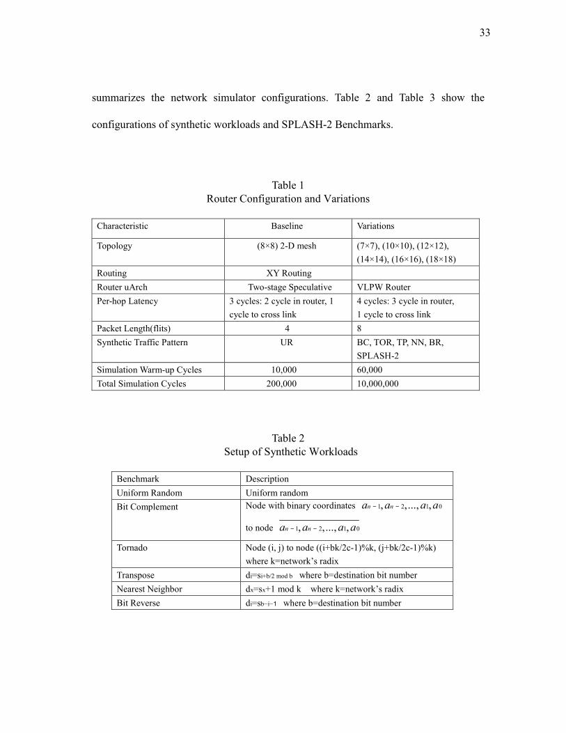
1 Router Configuration and Variations.......................................................... 33
2 Setup of Synthetic Workloads..................................................................... 33
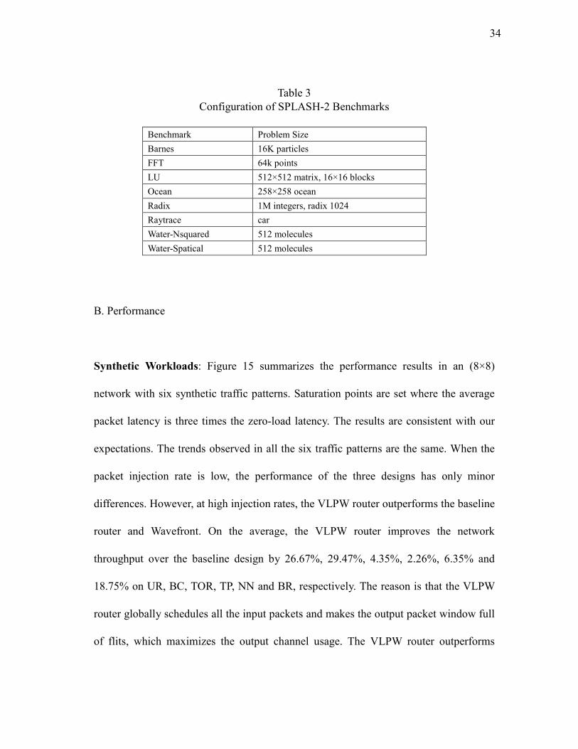
3 Configuration of SPLASH-2 Benchmarks.................................................. 34
1
CHAPTER I
INTRODUCTION
Moore’s law has steadily increased on-chip transistor density and integrated dozens of
components on a single die. Providing efficient communication in a single die is
becoming a critical factor for high performance Chip Multiprocessors (CMPs) [23] and
Systems-on-Chips (SoCs) [16]. Traditional shared buses and dedicated wires do not
meet the communication demands for future multi-core architectures. Moreover, the
shrinking technology exacerbates the imbalance between transistors and wires in terms
of delay, and power has embarked on a fervent search for efficient communication
designs [8]. In this regime, Network-On-Chip (NOC) is a promising architecture that
orchestrates chip-wide communications towards future many-core processors.
The state-of-the-art on-chip router designs for recent innovative tile-based CMPs such
as Intel Teraflop 80-core [9] and Tilera 64-core [28] use a modular packetswitching
fabric in which network channels are shared by multiple packet flows. Wormhole flow
control [4] was introduced to improve performance through finer granularity buffer and
channel control at flit level instead of packet level (one packet is composed of a number
of flits.). However, one potential problem of input queue systems is low throughput due
to Head-of-Line (HoL) blocking. To remedy this predicament, Virtual Channel (VC)
The thesis follows the style of IEEE Transactions on Parallel and Distributed Systems.
2
flow control [2] assigns multiple virtual paths to the same physical channel. Ideally with
unlimited number of VCs, routers will allow the maximum number of packets to share
the physical channels and achieves the highest throughput. Since buffer resources come
at a premium in resource-constrained NOC environments, the gap of throughput
between current state-of-the-art and ideal routers is quite large. It is imperative to
design a high throughput router with limited buffer budgets.
A paramount concern for any high throughput NOC router design is the ability to find
the best match between input ports and output ports. In the Internet, researchers propose
Virtual Output Queue (VOQ) [14, 22] and an input-queued [19] switch allocator that
can achieve 100% throughput. In VOQ each input port maintains a separate queue for
each output port. However, the implementation of VOQ heavily depends on topologies
in that the number of channels required in VOQ is determined by output directions.
Also it is hard to directly hire the algorithm in NOC designs without hurting the router
frequency.
To address these problems and design a practical high throughput NOC router, we
propose Very Long Packet Window (VLPW), which tries to close the throughput gap
between state-of-the-art on-chip routers and the ideal interconnect fabric. A VLPW
router globally schedules all the input packets, resolves the output conflicts, maximizes
the output channel usage, and finally achieves the best throughput in output channels.
3
With the VLPW architecture, we propose two scheduling schemes, called Global
Fairness (GFairness) and Global Diversity (GDiversity). GFairness is simply built upon
a Round-Robin scheduler but avoids packets competing for the same output port at the
second step of the Switch Allocation (SA) stage. Gdiversity dynamically assigns
different priorities to input ports with different number of output requests, which can
increase the Switch Allocation Efficiency (SAE), and improve the network throughput
further. Our simulation results show that a VLPW router achieves more than 20%
throughput improvement without negative effects on zero-load latency.
We first how the need for VLPW by analyzing the drawbacks of the current NOC router
scheduler in Chapter II. We summarize the related work in Chapter III. We present two
scheduling schemes and details of a VLPW router architecture in Chapter IV. In Chapter
V, we describe the evaluation methodology and summarize the simulation results.
Finally, we draw conclusions in Chapter VI.
4
CHAPTER II
BACKGROUND AND MOTIVATION
In this chapter, we provides background information on NOC research area, describe
the baseline state-of-the-art NOC router microarchitecture, introduce the generic
two-step switch arbiter, and present a motivating case study that highlights the
drawbacks of the existing scheduler hurting the router throughput.
A. Topology
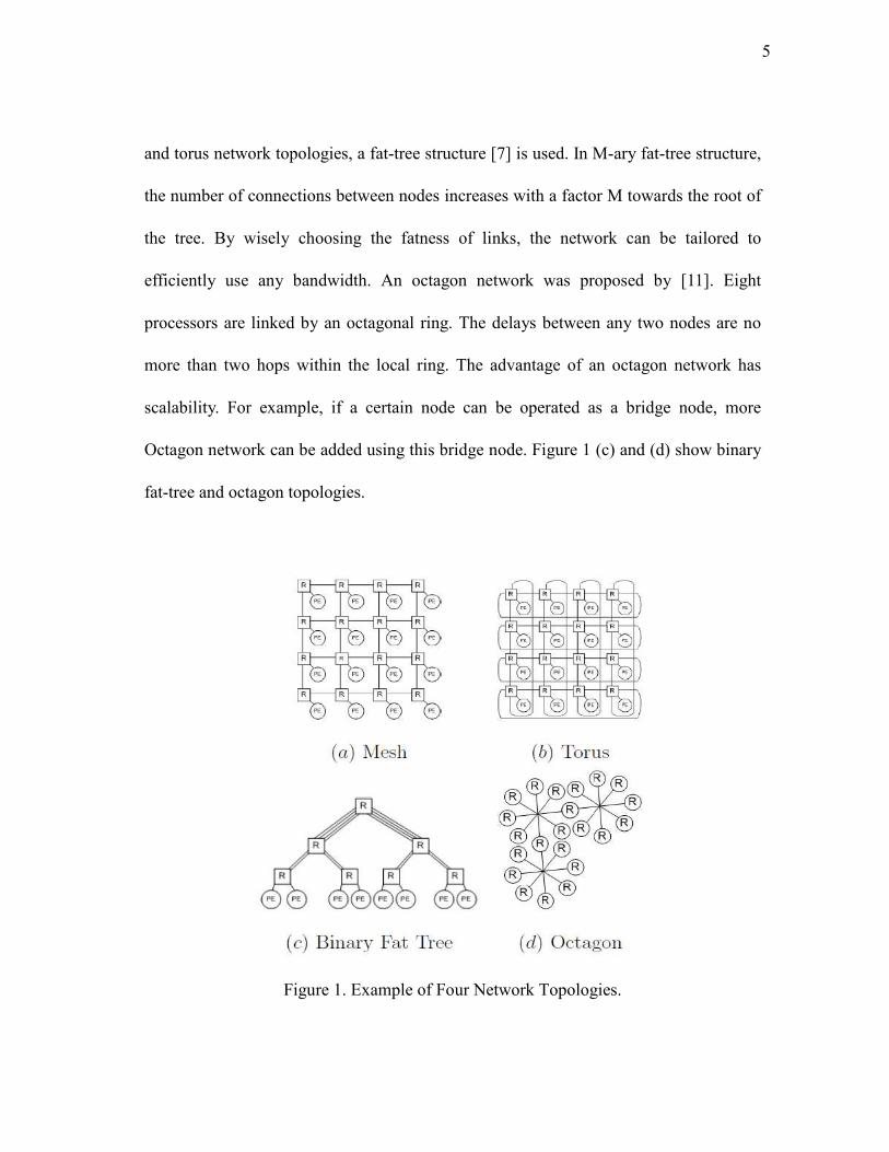
Topology determines the physical layout and connections between channels and
network. Mesh and torus network topologies are widely used in a NOC [5]. These two
network topologies have simple 2-D square structure. Figure 1 (a) shows a 2-D mesh
network structure. It is composed of a grid of horizontal and vertical lines of routers.
Mesh topology is mostly used since delay among routers can be predicted at a high
level. In a mesh network, the address of a router can be computed by the number of
horizontal nodes and the number of vertical nodes. 2-D torus topology is a
donut-shaped structure which is made by a 2-D mesh and connection of opposite sides
as we can see in Figure 1 (b). This topology has twice the bisection bandwidth of a
mesh network at the cost of a doubled wire demand. But the nodes should be
interleaved because all inter-node routers have the same length. In addition to the mesh
5
and torus network topologies, a fat-tree structure [7] is used. In M-ary fat-tree structure,
the number of connections between nodes increases with a factor M towards the root of
the tree. By wisely choosing the fatness of links, the network can be tailored to
efficiently use any bandwidth. An octagon network was proposed by [11]. Eight
processors are linked by an octagonal ring. The delays between any two nodes are no
more than two hops within the local ring. The advantage of an octagon network has
scalability. For example, if a certain node can be operated as a bridge node, more
Octagon network can be added using this bridge node. Figure 1 (c) and (d) show binary
fat-tree and octagon topologies.
Figure 1. Example of Four Network Topologies.
6
B. Routing
Routing algorithm is used to decide what path a packet will take through the network to
reach its destination. In general, routing algorithm can be either deterministic or
adaptive. For deterministic routing, such as XY routing, the routes between given pairs
of nodes are pre-programmed and thus follow the same path between two nodes. This
routing algorithm can cause a congested region in the network and poor utilization of
the network capacity. On the other hand, when adaptive routing is used, the path taken
by a packet may depend on other packets in order to improve performance and fault
tolerance. In adaptive router, each router should know the network traffic status in order
to avoid a congested region in advance [3].
In addition, modules which need heavy intercommunication should be placed close to
each other to minimize congestion. [3] states that adaptive routing can support higher
performance than the deterministic routing method with deadlock-free network.
However, higher performance requires a larger number of virtual channels. And a larger
number of virtual channels can cause long latency because of design complexity.
Therefore, if network traffic is not heavy and the in-order packet is delivered, the
deterministic routing could be selected.
7
C. Flow Control
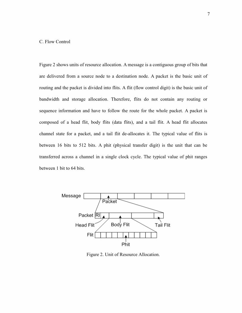
Figure 2 shows units of resource allocation. A message is a contiguous group of bits that
are delivered from a source node to a destination node. A packet is the basic unit of
routing and the packet is divided into flits. A flit (flow control digit) is the basic unit of
bandwidth and storage allocation. Therefore, flits do not contain any routing or
sequence information and have to follow the route for the whole packet. A packet is
composed of a head flit, body flits (data flits), and a tail flit. A head flit allocates
channel state for a packet, and a tail flit de-allocates it. The typical value of flits is
between 16 bits to 512 bits. A phit (physical transfer digit) is the unit that can be
transferred across a channel in a single clock cycle. The typical value of phit ranges
between 1 bit to 64 bits.
Figure 2. Unit of Resource Allocation.
8
Flow control mechanism determines which data is serviced first when a physical
channel has many data to be transferred. Flow control techniques are classified by the
granularity at which resource allocation occurs. We will discuss techniques that operate
on message, packet and flit granularities. There are typically four popular techniques:
store-and-forward, virtual cut-through, wormhole, and circuit switching. The first two
techniques are categorized into a packet-switching method, wormhole operates at the
flit-level and circuit switching operates at the message-level.
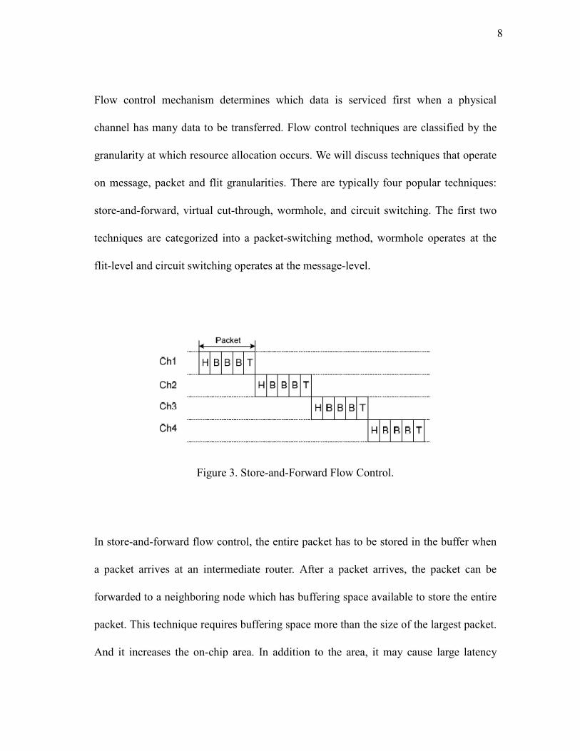
Figure 3. Store-and-Forward Flow Control.
In store-and-forward flow control, the entire packet has to be stored in the buffer when
a packet arrives at an intermediate router. After a packet arrives, the packet can be
forwarded to a neighboring node which has buffering space available to store the entire
packet. This technique requires buffering space more than the size of the largest packet.
And it increases the on-chip area. In addition to the area, it may cause large latency
9
because a certain packet cannot traverse to the next node until its whole packet is stored.
Figure 3 shows a store-and-forward switching technique and a flow diagram.
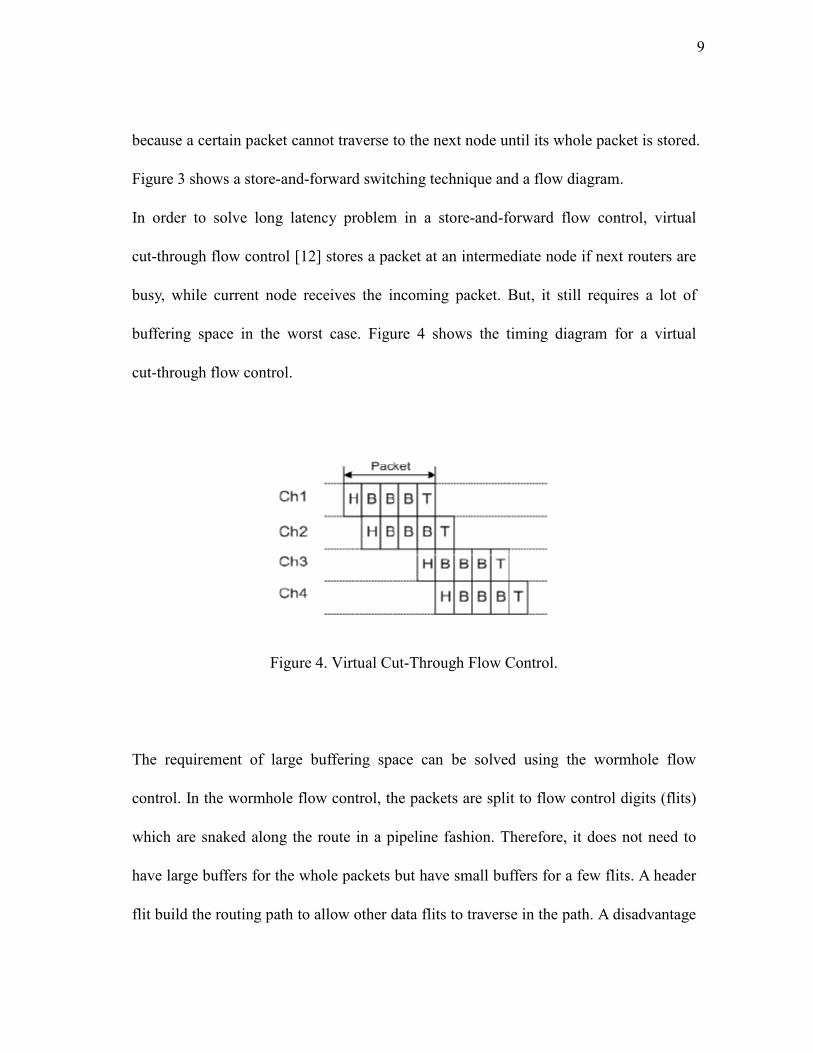
In order to solve long latency problem in a store-and-forward flow control, virtual
cut-through flow control [12] stores a packet at an intermediate node if next routers are
busy, while current node receives the incoming packet. But, it still requires a lot of
buffering space in the worst case. Figure 4 shows the timing diagram for a virtual
cut-through flow control.
Figure 4. Virtual Cut-Through Flow Control.
The requirement of large buffering space can be solved using the wormhole flow
control. In the wormhole flow control, the packets are split to flow control digits (flits)
which are snaked along the route in a pipeline fashion. Therefore, it does not need to
have large buffers for the whole packets but have small buffers for a few flits. A header
flit build the routing path to allow other data flits to traverse in the path. A disadvantage
10
of wormhole switching is that the length of the path is proportional to the number of
flits in the packet. In addition, the header flit is blocked by congestion, the whole chain
of flits are stalled. It also blocked other flits. This is called deadlock where network is
stalled because all buffers are full and circular dependency happens between nodes. The
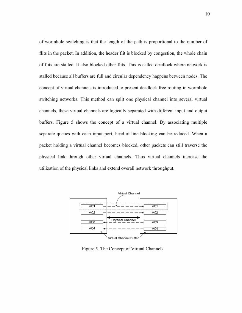
concept of virtual channels is introduced to present deadlock-free routing in wormhole
switching networks. This method can split one physical channel into several virtual
channels, these virtual channels are logically separated with different input and output
buffers. Figure 5 shows the concept of a virtual channel. By associating multiple
separate queues with each input port, head-of-line blocking can be reduced. When a
packet holding a virtual channel becomes blocked, other packets can still traverse the
physical link through other virtual channels. Thus virtual channels increase the
utilization of the physical links and extend overall network throughput.
Figure 5. The Concept of Virtual Channels.
11
For real-time streaming data, circuit switching supports a reserved, point-topoint
connection between a source node and a target node. Circuit switching has two phases:
circuit establishment and message transmission. Before message transmission, a
physical path from the source to the destination is reserved. A header flit arrives at the
destination node, and then an acknowledgement (ACK) flit is sent back to the source
node. As soon as the source node receives the ACK signal, the source node transmits an
entire message at the full bandwidth of the path. The circuit is released by the
destination node or by a tail flit. Even though circuit switching has the overhead of
circuit connection and release phase, if a data stream is very large to amortize the
overhead, circuit switching will be used continuously.
D. Buffering in Packet Switches
In a crossbar switch architecture, buffering is necessary to store packets because the
packets which arrive at nodes are unscheduled and should be multiplexed by control
information. Three buffering cases happen in a NOC router. The first buffering
condition is that the output port can receive only one packet at a time when two packets
arrive at the same output port at the same time. The second buffering condition is that
the next stage of network is blocked and the packet in the previous stage cannot be
routed into next router. And finally, a packet has to wait for arbitration time to get route
path in a current router, the current router must store this packet in buffer. Therefore, the
12
place of buffer space can be located in three parts: The Output Queue, The Input Queue,
and the Central Shared Queue.
Output Queues: In a buffer architecture, output queues can be used if output buffers
are large enough to accept all input packets, and switch fabric runs at least N times
faster than the speed of the input lines in an N by N switch. However, since high speed
switch fabric is currently not available and output queues have as many input ports as
an input line can support, output queue buffer architecture may make logic delay large
[26], [27].
Input Queues: Input buffers require only one input port in a packet switch because
only one packet can arrive at a time. Therefore, it can speed up performance with many
input ports. That is why many researchers use input queue buffer architecture. But, the
input queue buffer architecture has the HoL blocking problem. HoL can happen while a
packet in the head of queue waits for getting output port, another pacekt behind it can
not proceed to go to idle output port. HoL blocking significantly reduces throughput in
NOC.
Shared Central Queues: All the input ports and output ports can access shared central
buffer. For example, if the number of input ports is N and the number of output ports is
N, central buffer has minimum 2N ports for all input and output ports. As N increases,
13
access time to memory also increases which brings performance down. This large
access time should occur whenever packet transmission happens. In addition to
implementation difficulties, shared central buffer also causes down performance
because of large access time [27].
E. Generic NOC Router Architecture
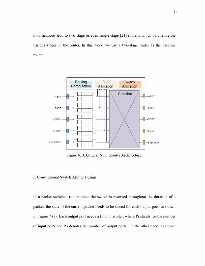
Figure 6 shows a generic NOC router architecture [5] for a 2-D mesh network. In usual
2-D mesh network, there are 5 ports: four from/to the cardinal directions (NORTH,
EAST, SOUTH and WEST) and one from/to the local Processing Element (PE). The
main building blocks of a generic NOC router [5] are input buffer, route computation
logic, VC allocator, switch allocator, and crossbar. To achieve high performance, routers
process packets with four pipeline stages, which are routing computation (RC), VC
allocation (VA), switch allocation (SA), and switch traversal (ST). When a packet
arrives at a router, the RC stage directs the packet to a proper output port by looking up
its destination address. Next, the VA stage allocates one available VC of the
downstream router determined by RC. The SA stage arbitrates input and output ports of
the crossbar, and successfully granted flits traverse the crossbar during the ST stage.
Considering that only the head flit needs routing computation and middle flits always
have to stall at the RC stage, low-latency router designs parallelize the RC, VA and SA
using lookahead routing [6] and speculative switch allocation [24]. These two
14
modifications lead to two-stage or even single-stage [21] routers, which parallelize the
various stages in the router. In this work, we use a two-stage router as the baseline
router.
Figure 6. A Generic NOC Router Architecture.
F. Conventional Switch Arbiter Design
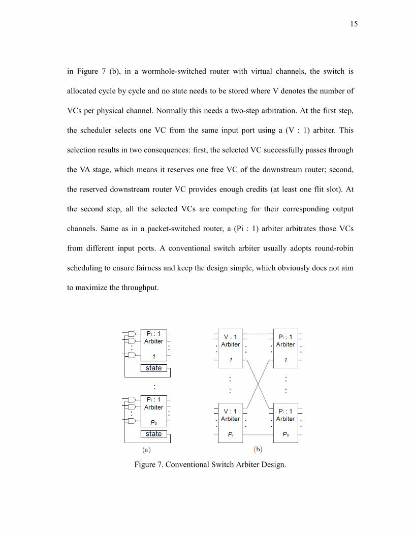
In a packet-switched router, since the switch is reserved throughout the duration of a
packet, the state of the current packet needs to be stored for each output port, as shown
in Figure 7 (a). Each output port needs a (Pi : 1) arbiter, where Pi stands for the number
of input ports and Po denotes the number of output ports. On the other hand, as shown
15
in Figure 7 (b), in a wormhole-switched router with virtual channels, the switch is
allocated cycle by cycle and no state needs to be stored where V denotes the number of
VCs per physical channel. Normally this needs a two-step arbitration. At the first step,
the scheduler selects one VC from the same input port using a (V : 1) arbiter. This
selection results in two consequences: first, the selected VC successfully passes through
the VA stage, which means it reserves one free VC of the downstream router; second,
the reserved downstream router VC provides enough credits (at least one flit slot). At
the second step, all the selected VCs are competing for their corresponding output
channels. Same as in a packet-switched router, a (Pi : 1) arbiter arbitrates those VCs
from different input ports. A conventional switch arbiter usually adopts round-robin
scheduling to ensure fairness and keep the design simple, which obviously does not aim
to maximize the throughput.
Figure 7. Conventional Switch Arbiter Design.
16
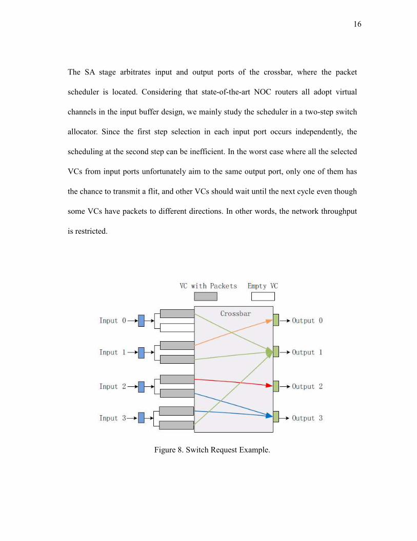
The SA stage arbitrates input and output ports of the crossbar, where the packet
scheduler is located. Considering that state-of-the-art NOC routers all adopt virtual
channels in the input buffer design, we mainly study the scheduler in a two-step switch
allocator. Since the first step selection in each input port occurs independently, the
scheduling at the second step can be inefficient. In the worst case where all the selected
VCs from input ports unfortunately aim to the same output port, only one of them has
the chance to transmit a flit, and other VCs should wait until the next cycle even though
some VCs have packets to different directions. In other words, the network throughput
is restricted.
Figure 8. Switch Request Example.
17
Figure 8 shows such an example, where the switch has four input ports and four output
ports. Each input port has two VCs. Input port 0 has only one flit to send to output 1,
while input port 1 has two flits: one for output 0 and the other for output 1. Input port 2
also has two flits: one for output 2 and the other for output 3. Meanwhile, input port 3
has two flits: one for output 3 and the other for output 1. In the generic router, the
scheduler for each input port is independent, which can incur many conflicts between
input ports. Since input port 0 only has one flit, it should be selected from input port 0.
However, without knowing the decision of input port 0, the scheduler of input 1 may
also select a flit whose destination is output 1. Similar scenarios can happen between
input 2 and 3. Then finally, in the current cycle, only two flits are successfully sent from
the router, which implies that only half of the four output channels are utilized.
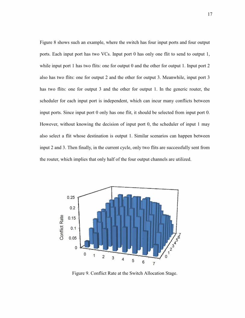
Figure 9. Conflict Rate at the Switch Allocation Stage.
18
An analysis of the conflict rate at the SA stage is shown in Figure 9. Here conflicts
denote the selected requests in the first step fail to be granted to the requested outputs in
the second step because they compete for the same outputs. The conflict rate is
calculated by total number of conflicts divided by total number of first step arbitration.
We use an (8×8) 2-D mesh network with a Uniform Random traffic under 0.30 network
injection rate. The x-axis and y-axis denotes the coordinates of a router in the 2-D mesh
network. The detailed router configuration is described in Chapter V. Each bar stands
for the conflict rate at the SA stage with the generic router design. It is observed that the
conflict rate can reach over 20% in the center area of the network, although at the edge
it is less than 10%. This inefficient SA stage design definitely will degrade the router
throughput
19
CHAPTER III
RELATED WORK
Many sophisticated studies have been proposed to achieve high throughput in switched
networks. Most of them fall into two categories: buffer design or switch scheduling.
Distributed Shared-Buffer (DSB) router architecture [25] buffers flits in the middle
memories to solve the packets’ arrival and departure conflicts with the help of extra
buffers and crossbars, which introduces 35% and 58% overhead in power and area,
respectively. ViChaR [22] makes full use of every flit slot in the buffer pool to improve
the buffer utilization with small buffer sizes. The new incoming flit is stored in the
buffer as long as there is a free slot in the buffer pool and flits within a packet can be
distributed anywhere in the buffer. With carefully designed buffer scheduling, ViChaR
achieves optimal throughput but incurs complicated VA and SA arbitrations which make
the design impractical. Xu et al. propose virtual channel allocation mechanisms: Fixed
VC Assignment with Dynamic VC Allocation (FVADA) and Adjustable VC
Assignment with Dynamic VC Allocation (AVADA) [30] to optimize throughput.
FVADA and AVADA introduce different priorities for different VCs, so that the VA
allocation can arbitrate more efficiently and quickly. A “home VC” with a higher
priority is introduced. At the VA stage, the VA arbiter first tries to allocate the “home
VC” to the incoming packets. A packet can be buffered in any free VCs if the “home
20
VC” is not available. FVADA and AVADA reduce pipeline stage delays by providing a
simple VA arbitration, but only achieve minor throughput improvement.
Switch scheduling is also explored in many previous works to improve the network
throughput. An output-first separable speculative switch allocator with a Wavefront
arbiter is proposed in [1] to reduce the delay of VC and switch allocators in on-chip
networks. The Wavefront assigns priority orders to inputs (e.g. WEST, EAST, NORTH
and SOUTH) and VCs (e.g. VC0, VC1, VC2 and VC3). Arbitration starts from the
highest priority VC (e.g. VC0 of WEST input port). Based on the first arbitration, the
second arbitration starts from the next VC of the next input port. For example, assuming
that VC1 of WEST is granted in the first arbitration, the second arbitration starts from
VC2 of EAST input port. Wavefront may avoid arbitration conflicts in certain cases
therefore it is a throughput optimal design. However, due to its nature, the lower
priority input ports always potentially suffer from starvation problems. Moreover, it is
proved that the VC allocation quality has little overall impact on network performance
and the switch scheduling becomes less effective when the network is saturated. Hence
the network throughput is less than that of the conventional baseline router in some
traffic patterns. McKeown proposes a novel switch scheduling approach for achieving
100% throughput in internetworking protocol routers, LAN and asynchronous transfer
mode (ATM) switches in iSLIP [17], [18]. Due to the constrained resources on a chip, it
is difficult to apply iSLIP directly to on-chip networks. Kumar et al. [14] design novel
21
switch allocators, which dynamically vary the number of requests presented by each
input port to the global allocation phase, to avoid switch contention. However, the
overall throughput improvement is minor even with large input buffers.
Compared with the previous work, we attempt to provide comparable throughput
improvement with negligible extra power consumption and modest wiring overhead,
which makes it a promising router design for future on-chip networks.
22
CHAPTER IV
VLPW ROUTER DESIGN
In this chapter, we elucidate the VLPW router microarchitecture and propose two
scheduling schemes.
A. What is VLPW?
The Very Long PacketWindow (VLPW) architecture adopts a different packet format in
which flits come from all different packets and aim to different directions. The packet
window is determined by the number of output directions of a router, which is related to
the topology. For example, in a 2-D mesh topology, considering five output directions
(NORTH, SOUTH, EAST, WEST and EJECTION) the VLPW packet window is five
flits while in Flattened Butterfly [13] the packet window is seven. Since the VLPW
architecture is independent of network topologies, in the following discussion we
mainly focus on a 2-D mesh topology. After the Switch Arbitration, the window is filled
with flits from different input ports and mapping to the corresponding output ports. The
VLPW router can achieve high throughput and efficient bandwidth usage because it
tries to maximize the VLPW window occupancy to improve throughput by avoiding
potential output link conflicts. With the VLPWarchitecture, we propose two scheduling
schemes, named Global Fairness (GFairness) and Global Diversity (GDiversity).
23
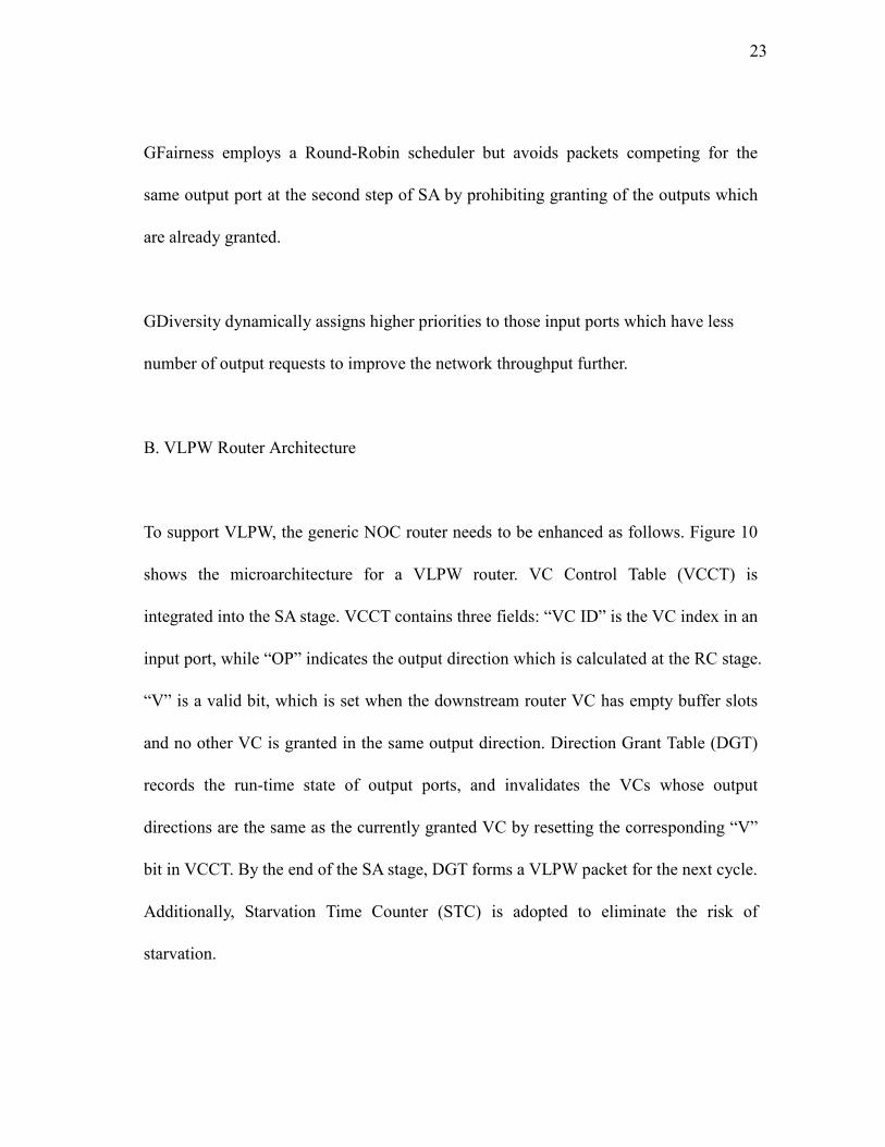
GFairness employs a Round-Robin scheduler but avoids packets competing for the
same output port at the second step of SA by prohibiting granting of the outputs which
are already granted.
GDiversity dynamically assigns higher priorities to those input ports which have less
number of output requests to improve the network throughput further.
B. VLPW Router Architecture
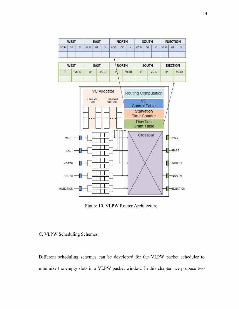
To support VLPW, the generic NOC router needs to be enhanced as follows. Figure 10
shows the microarchitecture for a VLPW router. VC Control Table (VCCT) is
integrated into the SA stage. VCCT contains three fields: “VC ID” is the VC index in an
input port, while “OP” indicates the output direction which is calculated at the RC stage.
“V” is a valid bit, which is set when the downstream router VC has empty buffer slots
and no other VC is granted in the same output direction. Direction Grant Table (DGT)
records the run-time state of output ports, and invalidates the VCs whose output
directions are the same as the currently granted VC by resetting the corresponding “V”
bit in VCCT. By the end of the SA stage, DGT forms a VLPW packet for the next cycle.
Additionally, Starvation Time Counter (STC) is adopted to eliminate the risk of
starvation.
24
Figure 10. VLPW Router Architecture.
C. VLPW Scheduling Schemes
Different scheduling schemes can be developed for the VLPW packet scheduler to
minimize the empty slots in a VLPW packet window. In this chapter, we propose two
25
schemes: GFairness and GDiversity.
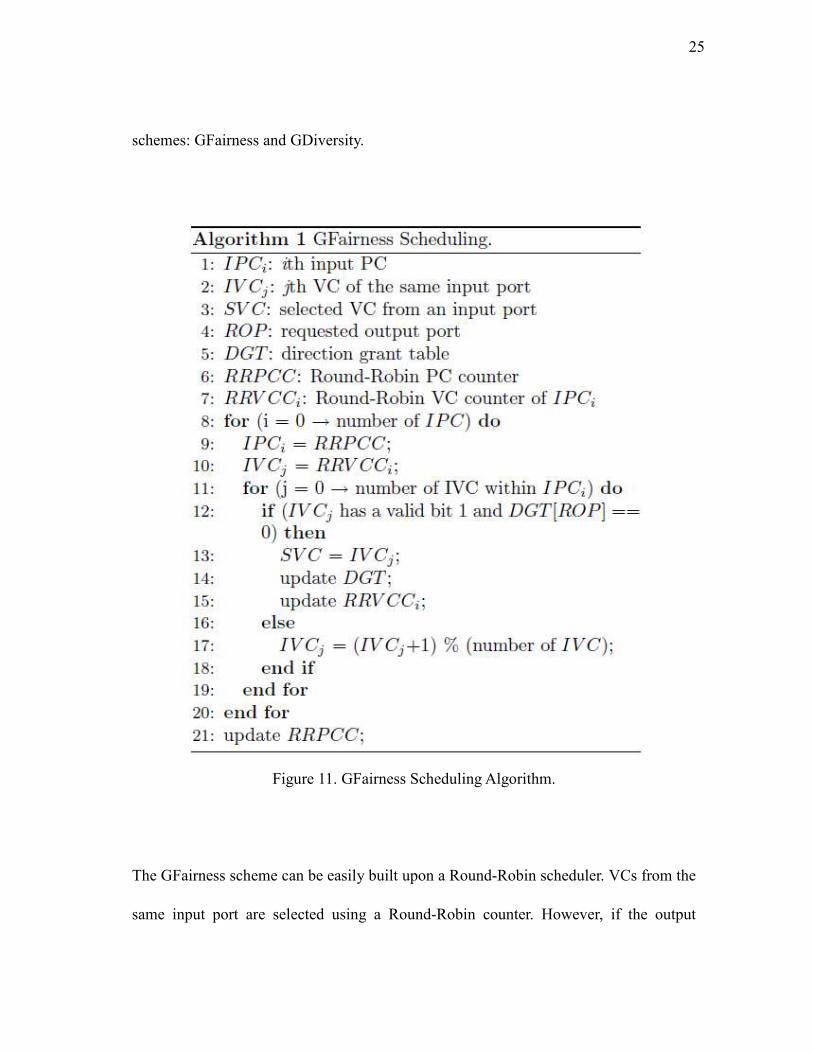
Figure 11. GFairness Scheduling Algorithm.
The GFairness scheme can be easily built upon a Round-Robin scheduler. VCs from the
same input port are selected using a Round-Robin counter. However, if the output
26
direction of the currently selected VC has been granted to another VC from a different
input port, we skip this selected VC, and the next VC of the same input port is selected
until no output conflict is found. When a VC is selected to occupy one field of DGT,
DGT invalidates other VCs which aim to the same direction to make sure no output
conflict occurs. The detailed procedure of GFairness scheme is in Figure 11.
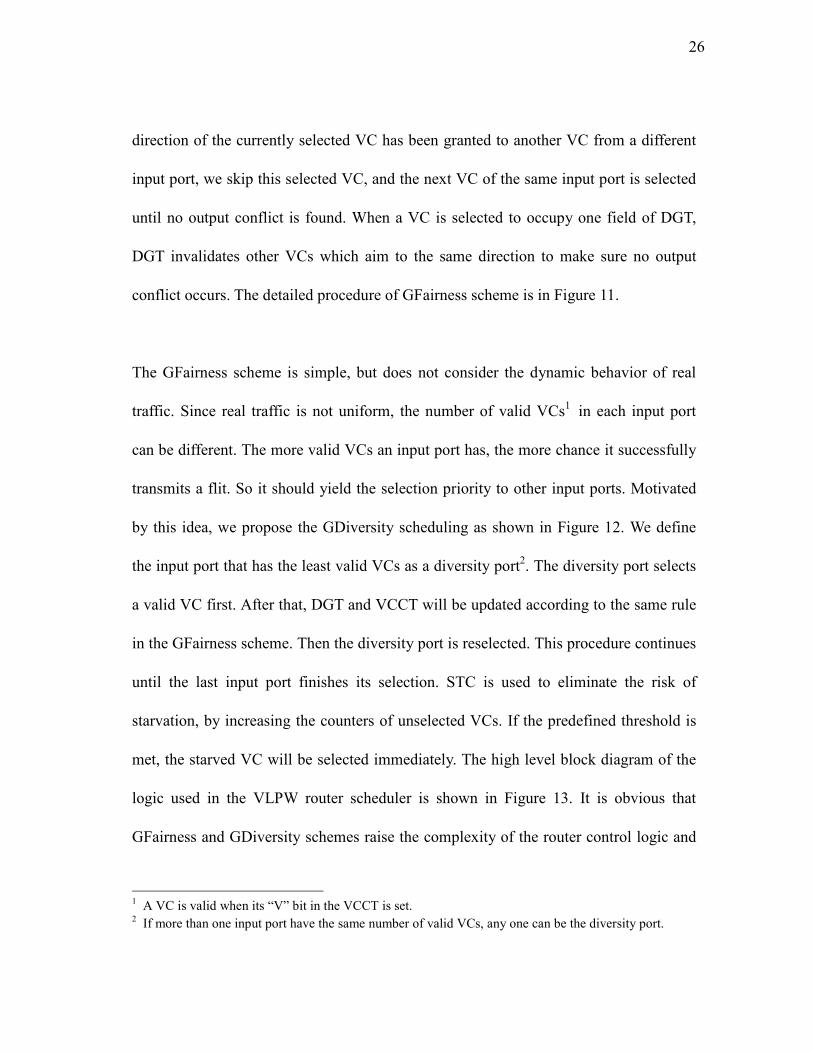
The GFairness scheme is simple, but does not consider the dynamic behavior of real
traffic. Since real traffic is not uniform, the number of valid VCs1 in each input port
can be different. The more valid VCs an input port has, the more chance it successfully
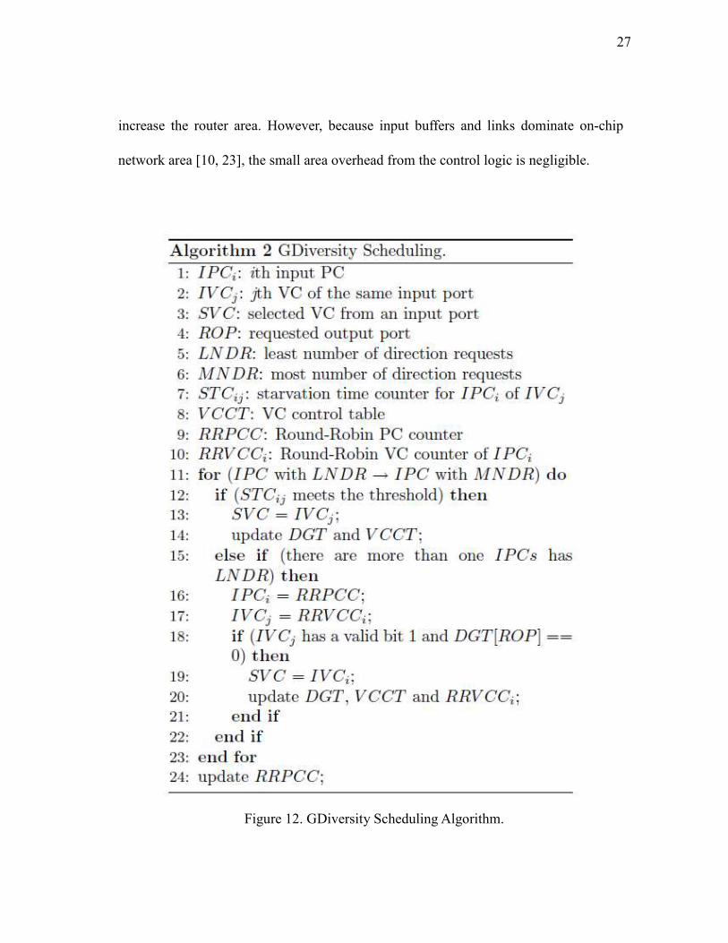
transmits a flit. So it should yield the selection priority to other input ports. Motivated
by this idea, we propose the GDiversity scheduling as shown in Figure 12. We define
the input port that has the least valid VCs as a diversity port2. The diversity port selects
a valid VC first. After that, DGT and VCCT will be updated according to the same rule
in the GFairness scheme. Then the diversity port is reselected. This procedure continues
until the last input port finishes its selection. STC is used to eliminate the risk of
starvation, by increasing the counters of unselected VCs. If the predefined threshold is
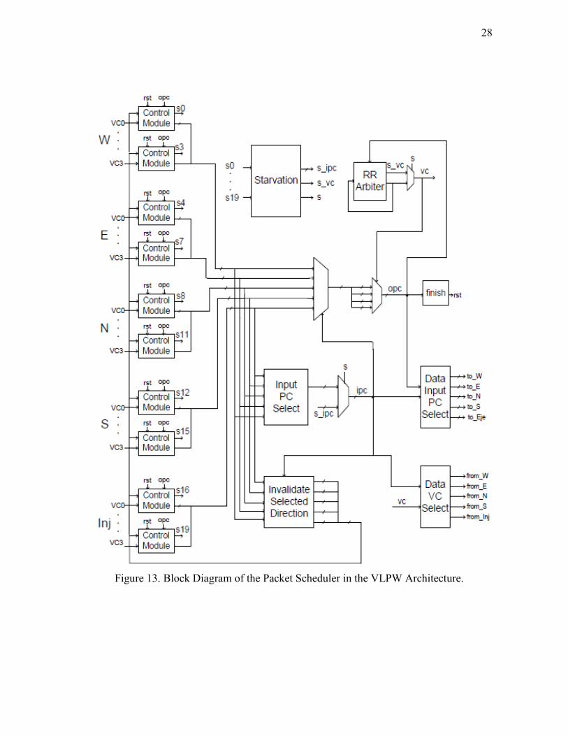
met, the starved VC will be selected immediately. The high level block diagram of the
logic used in the VLPW router scheduler is shown in Figure 13. It is obvious that
GFairness and GDiversity schemes raise the complexity of the router control logic and
1 A VC is valid when its “V” bit in the VCCT is set.
2 If more than one input port have the same number of valid VCs, any one can be the diversity port.
27
increase the router area. However, because input buffers and links dominate on-chip
network area [10, 23], the small area overhead from the control logic is negligible.
Figure 12. GDiversity Scheduling Algorithm.
28
Figure 13. Block Diagram of the Packet Scheduler in the VLPW Architecture.
29
D. Walkthrough Example
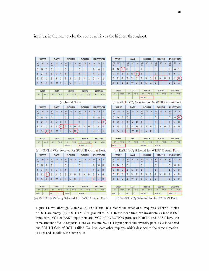
We use a walkthrough example in Figure 14 to illustrate the process of GDiversity
scheduling. The rectangle denotes the granted VC in the current step, while the circle
means the requests are no longer valid since this output port is occupied by the
rectangle request.
(a) VCCT and DGT record the status of all requests. For example, in the WEST input
port, there are four valid requests targeting for NORTH, EJECTION, EAST and
SOUTH, respectively. All fields of DGT are empty.
(b) SOUTH input port is the current diversity port, which is decided by “Input PC
Selected” component in Figure 13. Therefore in DGT, NORTH output port is
granted to VC2 of SOUTH input. VC0 of WEST input port, VC1 of EAST input
port and VC2 of INJECTION port become invalid because they compete for
NORTH output port which is granted.
(c) NORTH and EAST have the same amount of valid requests. Let’s assume NORTH
input port is the diversity port according to the current status of “RR Arbiter” in
Figure 13. NORTH input port has two VCs aim to SOUTH output port. VC2 is
selected and SOUTH field of DGT is filled.
Steps (d), (e) and (f) follow the same rules. Finally, a VLPW packet is generated
according to the fields in DGT. In this example, all the fields in DGT are full, which
30
implies, in the next cycle, the router achieves the highest throughput.
Figure 14. Walkthrough Example. (a) VCCT and DGT record the states of all requests, where all fields
of DGT are empty. (b) SOUTH VC2 is granted to DGT. In the mean time, we invalidate VC0 of WEST
input port, VC1 of EAST input port and VC2 of INJECTION port. (c) NORTH and EAST have the
same amount of valid requests. Here we assume NORTH input port is the diversity port. VC2 is selected
and SOUTH field of DGT is filled. We invalidate other requests which destined to the same direction.
(d), (e) and (f) follow the same rules.
31
E. Timing
NOC router pipeline stage delays are quite imbalanced unlike the processor pipeline [24]
since, normally, the VA stage is the bottleneck [20]. However, compared with the
generic router design, the VLPW router architecture introduces more logic into the SA
stage, which incurs extra time overhead. According to our HSPICE simulations using
45 nm technology, the SA stage in the VLPW router design takes 585ps, which is larger
than the delay of the VA stage (328ps). Recently Das et al. [20] have proposed a time
stealing technology, in which a slower stage in the router gains time by stealing time
from successive or previous router pipeline stages. Considering the relative lower delay
of the ST stage, the SA stage can steal time from the ST stage by delaying the triggering
edge of the clock to all the subsequent latches. Without loss of generality, we evaluate
the VLPW architecture with one-cycle and two-cycle SA.
32
CHAPTER V
EXPERIMENTAL EVALUATION
We evaluate the proposed VLPW router using both synthetic workloads and real
applications by comparing it with the state-of-the-art baseline router and Wavefront [1].
We also study the VLPW router performance in different network sizes.
A. Methodology
We use a cycle-accurate network simulator that models all router pipeline delays and
wire latencies, and Orion 2.0 [10] for power estimation. Each router has 5 input/output
ports, and each port has 4 VCs in the baseline design. We model a link as 128 parallel
wires, which takes advantage of abundant metal resources provided by future
multi-layer interconnects. We evaluate the proposed VLPW router using both synthetic
workloads and real applications. Synthetic workloads show specific features and
aspects of the on-chip network while the SPLASH2 suite [29] denotes realistic
performance. We use six synthetic workloads (Uniform Random (UR), Bit Complement
(BC), Tornado (TOR), Transpose (TP), Nearest Neighbor (NN) and Bit Reverse (BR)).
The SPLASH-2 traces were gathered from a 49 nodes, shared memory CMP full system
simulator, arranged in a (7×7) 2-D mesh topology [15]. Our network simulator is
configured to match the environment in which the traces were obtained. Table 1
33
summarizes the network simulator configurations. Table 2 and Table 3 show the
configurations of synthetic workloads and SPLASH-2 Benchmarks.
Table 1
Router Configuration and Variations
Characteristic Baseline Variations
Topology (8×8) 2-D mesh (7×7), (10×10), (12×12),
(14×14), (16×16), (18×18)
Routing XY Routing
Router uArch Two-stage Speculative VLPW Router
Per-hop Latency 3 cycles: 2 cycle in router, 1
cycle to cross link
4 cycles: 3 cycle in router,
1 cycle to cross link
Packet Length(flits) 4 8
Synthetic Traffic Pattern UR BC, TOR, TP, NN, BR,
SPLASH-2
Simulation Warm-up Cycles 10,000 60,000
Total Simulation Cycles 200,000 10,000,000
Table 2
Setup of Synthetic Workloads
Benchmark Description
Uniform Random Uniform random
Bit Complement Node with binary coordinates 1 2 1 0, ,..., ,n na a a a− −
to node 1 2 1 0, ,..., ,n na a a a− −
Tornado Node (i, j) to node ((i+bk/2c-1)%k, (j+bk/2c-1)%k)
where k=network’s radix
Transpose di=si+b/2 mod b where b=destination bit number
Nearest Neighbor dx=sx+1 mod k where k=network’s radix
Bit Reverse di=sb−i−1 where b=destination bit number
34
Table 3
Configuration of SPLASH-2 Benchmarks
Benchmark Problem Size
Barnes 16K particles
FFT 64k points
LU 512×512 matrix, 16×16 blocks
Ocean 258×258 ocean
Radix 1M integers, radix 1024
Raytrace car
Water-Nsquared 512 molecules
Water-Spatical 512 molecules
B. Performance
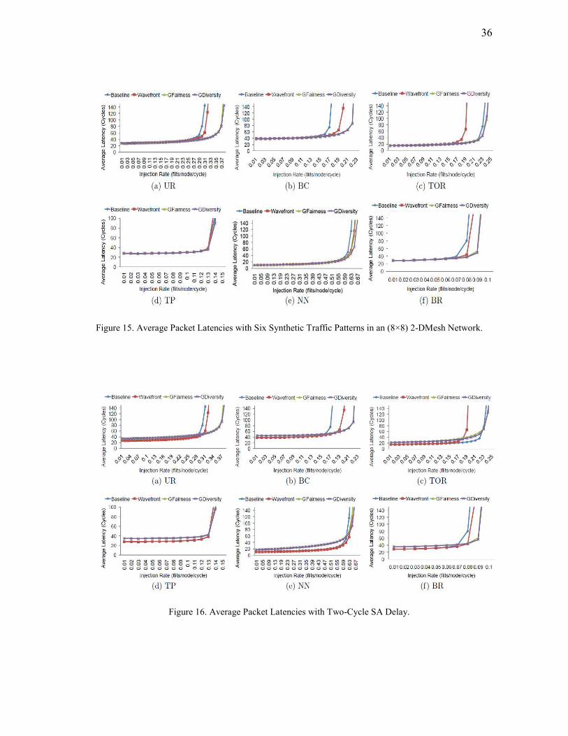
Synthetic Workloads: Figure 15 summarizes the performance results in an (8×8)
network with six synthetic traffic patterns. Saturation points are set where the average
packet latency is three times the zero-load latency. The results are consistent with our
expectations. The trends observed in all the six traffic patterns are the same. When the
packet injection rate is low, the performance of the three designs has only minor
differences. However, at high injection rates, the VLPW router outperforms the baseline
router and Wavefront. On the average, the VLPW router improves the network
throughput over the baseline design by 26.67%, 29.47%, 4.35%, 2.26%, 6.35% and
18.75% on UR, BC, TOR, TP, NN and BR, respectively. The reason is that the VLPW
router globally schedules all the input packets and makes the output packet window full
of flits, which maximizes the output channel usage. The VLPW router outperforms
35
Wavefront by 18.75%, 15.79%, 26.31%, 3.57%, 1.54% and 11.76% on UR, BC, TOR,
TP, NN and BR, respectively, because Wavefront gives higher priority to fixed VCs,
which does not consider the global requests in the whole router. The baseline router
even outperforms Wavefront in TOR because Wavefront does not ensure fairness which
makes the VCs with lower priorities suffer from starvation problems. However, we do
not see much difference in the throughput between GFairness and GDiversity. At high
injection rates, almost all the VCs of each input port become full. The advantage of
GDiversity over GFairness scheme comes from the nonuniform distribution of packets
in different input ports. This characteristic diminishes when the injection rate is high.
That’s why the difference between GFairness and GDiversity becomes minor.
Considering the extra time overhead at the SA stage, we evaluate our schemes with
two-cycle SA, as shown in Figure 16. As we expect, the latencies among low injection
rates are higher than Baseline and Wavefront because the SA stage takes two cycles.
The improvement we gain from the carefully designed switch arbiter cannot be
observed at low injection rates. However, as the injection rate increases, the VLPW
router starts to outperform the baseline and Wavefront because it avoids potential
conflicts with global scheduling. The benefits we gain from the VLPW router
outweighs the minor losses in the SA stage when the injection rate is high.
36
Figure 15. Average Packet Latencies with Six Synthetic Traffic Patterns in an (8×8) 2-DMesh Network.
Figure 16. Average Packet Latencies with Two-Cycle SA Delay.
37
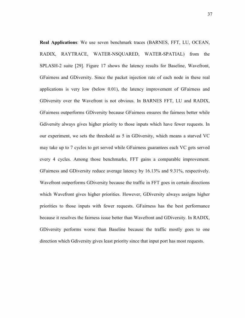
Real Applications: We use seven benchmark traces (BARNES, FFT, LU, OCEAN,
RADIX, RAYTRACE, WATER-NSQUARED, WATER-SPATIAL) from the
SPLASH-2 suite [29]. Figure 17 shows the latency results for Baseline, Wavefront,
GFairness and GDiversity. Since the packet injection rate of each node in these real
applications is very low (below 0.01), the latency improvement of GFairness and
GDiversity over the Wavefront is not obvious. In BARNES FFT, LU and RADIX,
GFairness outperforms GDiversity because GFairness ensures the fairness better while
Gdiversity always gives higher priority to those inputs which have fewer requests. In
our experiment, we sets the threshold as 5 in GDiversity, which means a starved VC
may take up to 7 cycles to get served while GFairness guarantees each VC gets served
every 4 cycles. Among those benchmarks, FFT gains a comparable improvement.
GFairness and GDiversity reduce average latency by 16.13% and 9.31%, respectively.
Wavefront outperforms GDiversity because the traffic in FFT goes in certain directions
which Wavefront gives higher priorities. However, GDiversity always assigns higher
priorities to those inputs with fewer requests. GFairness has the best performance
because it resolves the fairness issue better than Wavefront and GDiversity. In RADIX,
GDiversity performs worse than Baseline because the traffic mostly goes to one
direction which Gdiversity gives least priority since that input port has most requests.
38
Figure 17. Average Packet Latencies of SPLASH-2 Benchmarks.
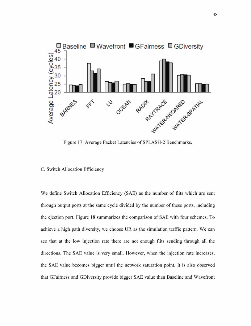
C. Switch Allocation Efficiency
We define Switch Allocation Efficiency (SAE) as the number of flits which are sent
through output ports at the same cycle divided by the number of these ports, including
the ejection port. Figure 18 summarizes the comparison of SAE with four schemes. To
achieve a high path diversity, we choose UR as the simulation traffic pattern. We can
see that at the low injection rate there are not enough flits sending through all the
directions. The SAE value is very small. However, when the injection rate increases,
the SAE value becomes bigger until the network saturation point. It is also observed
that GFairness and GDiversity provide bigger SAE value than Baseline and Wavefront
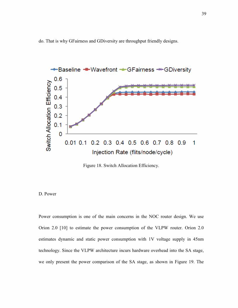
39
do. That is why GFairness and GDiversity are throughput friendly designs.
Figure 18. Switch Allocation Efficiency.
D. Power
Power consumption is one of the main concerns in the NOC router design. We use
Orion 2.0 [10] to estimate the power consumption of the VLPW router. Orion 2.0
estimates dynamic and static power consumption with 1V voltage supply in 45nm
technology. Since the VLPW architecture incurs hardware overhead into the SA stage,
we only present the power comparison of the SA stage, as shown in Figure 19. The
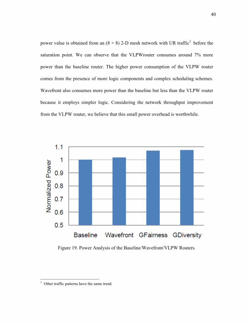
40
power value is obtained from an (8 × 8) 2-D mesh network with UR traffic3 before the
saturation point. We can observe that the VLPWrouter consumes around 7% more
power than the baseline router. The higher power consumption of the VLPW router
comes from the presence of more logic components and complex scheduling schemes.
Wavefront also consumes more power than the baseline but less than the VLPW router
because it employs simpler logic. Considering the network throughput improvement
from the VLPW router, we believe that this small power overhead is worthwhile.
Figure 19. Power Analysis of the Baseline/Wavefront/VLPW Routers.
3 Other traffic patterns have the same trend.
41
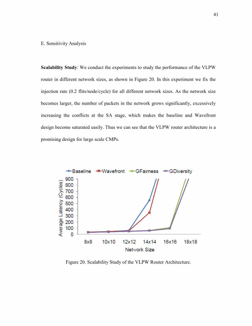
E. Sensitivity Analysis
Scalability Study: We conduct the experiments to study the performance of the VLPW
router in different network sizes, as shown in Figure 20. In this experiment we fix the
injection rate (0.2 flits/node/cycle) for all different network sizes. As the network size
becomes larger, the number of packets in the network grows significantly, excessively
increasing the conflicts at the SA stage, which makes the baseline and Wavefront
design become saturated easily. Thus we can see that the VLPW router architecture is a
promising design for large scale CMPs.
Figure 20. Scalability Study of the VLPW Router Architecture.
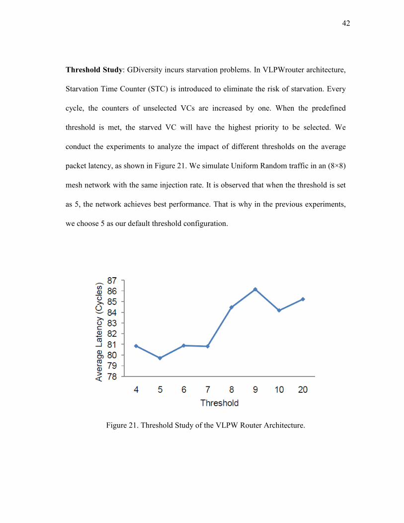
42
Threshold Study: GDiversity incurs starvation problems. In VLPWrouter architecture,
Starvation Time Counter (STC) is introduced to eliminate the risk of starvation. Every
cycle, the counters of unselected VCs are increased by one. When the predefined
threshold is met, the starved VC will have the highest priority to be selected. We
conduct the experiments to analyze the impact of different thresholds on the average
packet latency, as shown in Figure 21. We simulate Uniform Random traffic in an (8×8)
mesh network with the same injection rate. It is observed that when the threshold is set
as 5, the network achieves best performance. That is why in the previous experiments,
we choose 5 as our default threshold configuration.
Figure 21. Threshold Study of the VLPW Router Architecture.
43
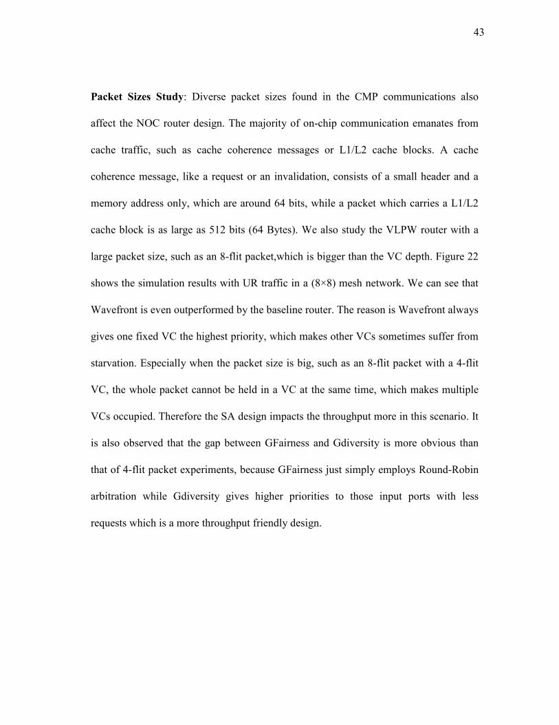
Packet Sizes Study: Diverse packet sizes found in the CMP communications also
affect the NOC router design. The majority of on-chip communication emanates from
cache traffic, such as cache coherence messages or L1/L2 cache blocks. A cache
coherence message, like a request or an invalidation, consists of a small header and a
memory address only, which are around 64 bits, while a packet which carries a L1/L2
cache block is as large as 512 bits (64 Bytes). We also study the VLPW router with a
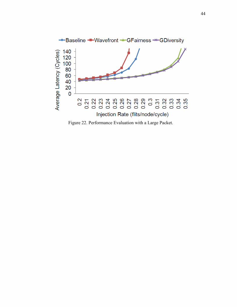
large packet size, such as an 8-flit packet,which is bigger than the VC depth. Figure 22
shows the simulation results with UR traffic in a (8×8) mesh network. We can see that
Wavefront is even outperformed by the baseline router. The reason is Wavefront always
gives one fixed VC the highest priority, which makes other VCs sometimes suffer from
starvation. Especially when the packet size is big, such as an 8-flit packet with a 4-flit
VC, the whole packet cannot be held in a VC at the same time, which makes multiple
VCs occupied. Therefore the SA design impacts the throughput more in this scenario. It
is also observed that the gap between GFairness and Gdiversity is more obvious than
that of 4-flit packet experiments, because GFairness just simply employs Round-Robin
arbitration while Gdiversity gives higher priorities to those input ports with less
requests which is a more throughput friendly design.
44
Figure 22. Performance Evaluation with a Large Packet.
45
CHAPTER VI
CONCLUSIONS
In this work, we proposed the Very Long Packet Window (VLPW) architecture for
on-chip networks. The VLPW router design globally schedules all the input packets,
resolves the output conflicts and achieves high throughput. With the VLPW architecture,
we propose two scheduling schemes: Global Fairness (GFairness) and Global Diversity
(GDiversity). GFairness is simply built upon a Round-Robin scheduler but avoids
packets competing for the same output port at the second step of SA. Based on
GFairness, GDiversity dynamically assigns priorities to different input ports to improve
the network throughput further. Our simulation results show that the VLPW router
achieves more than 20% throughput improvement without negative effects on zero-load
latency compared with that of the baseline router. Comparing to a state-of-the-art
baseline router, VLPW incurs negligible power consumption and modest wiring
overhead. Furthermore, the VLPW architecture is more suitable for large-scale network
designs, since it is less saturated as the network size grows.
46
REFERENCES
[1] D.U. Becker and W.J. Dally, “Allocator Implementations for Network-On-Chip
Routers,” Proc. SC, 2009, pp. 1-12.
[2] W.J. Dally, “Virtual-Channel Flow Control,” Proc. ISCA, 1990, pp. 60–68.
[3] W.J. Dally and H. Aoki, “Deadlock-Free Adaptive Routing in Multicomputer
Networks Using Virtual Channels,” IEEE Trans. Parallel Distrib. Syst., vol. 4, no.
4, pp.466–475, Jun. 1993.
[4] W.J. Dally and C.L. Seitz, “The Torus Routing Chip,” Distributed Computing,
vol. 1, no. 4, pp. 187–196, Jan. 1986.
[5] W.J. Dally and B. Towles, Principles and Practices of Interconnection �etworks.
Burlington, MA: Morgan Kaufmann, 2003.
[6] M. Galles, “Scalable Pipelined Interconnect for Distributed Endpoint Routing:
The SGI SPIDER Chip,” Proc. Hot Interconnect 4, 2009, pp. 141–146.
[7] P. Guerrier and A. Greiner, “A Generic Architecture for On-Chip
Packet-Switched Interconnections,” Proc. DATE, 2000, pp. 250–256.
[8] R. Ho, K. Mai, and M. Horowitz, “The Future of Wires,” Proc. IEEE, 2001, pp.
490–504.
[9] Y. Hoskote, S. Vangal, A. Singh, N. Borkar, and S. Borkar, “A 5-GHz Mesh
Interconnect for a Teraflops Processor,” IEEE Micro, vol. 27, no. 5, pp. 51–61,
Oct. 2007.
47
[10] A.B. Kahng, B. Li, L.-S. Peh, and K. Samadi, “ORION 2.0: A Fast and Accurate
NoC Power and Area Model for Early-Stage Design Space Exploration,” Proc.
DATE, 2009, pp. 423–428.
[11] F. Karim, A. Nguyen, S. Dey, and R. Rao, “On-Chip Communication
Architecture for OC-768 Network Processors,” Proc. DAC, 2001, pp. 678–683.
[12] P. Kernani and L. Kleinrock, “Virtual Cut-Through: A New Computer
Communication Switching Technique,” Computer �etwork, vol. 3, no. 2, pp.
267–286, Sept. 1979.
[13] J. Kim, J. Balfour, and W.J. Dally, “Flattened Butterfly Topology for On-Chip
Networks,” Proc. MICRO, 2007, pp. 172–182.
[14] A. Kumar, P. Kundu, A.P. Singh, L.-S. Peh, and N.K. Jha, “A 4.6Tbits/s 3.6GHz
Single-Cycle NoC Router with a Novel Switch Allocator in 65nm CMOS,” Proc.
ICCD, 2007, pp. 63–70.
[15] A. Kumar, L.-S. Peh, P. Kundu, and N.K. Jha, “Express Virtual Channels:
Towards the Ideal Interconnection Fabric,” Proc. ISCA, 2007, pp. 150–161.
[16] R. Marculescu, U.Y. Ogras, L.-S. Peh, N.D.E. Jerger, and Y.V. Hoskote,
“Outstanding Research Problems in NOC Design: System, Microarchitecture, and
Circuit Perspectives,” IEEE Trans. on CAD of Integrated Circuits and Systems,
vol. 28, no. 1, pp. 3–21, Jan. 2009.
[17] N. McKeown, “The Islip Scheduling Algorithm for Input-Queued Switches,”
IEEE/ACM Trans. �etw., vol. 7, no. 2, pp. 188–201, Apr. 1999.
48
[18] N. McKeown, V. Anantharam, and J.C. Walrand, “Achieving 100% Throughput
in an Input-Queued Switch,” Proc. I�FOCOM, 1996, pp. 296–302.
[19] A. Mekkittikul and N. McKeown, “A Practical Scheduling Algorithm to Achieve
100% Throughput in Input-Queued Switches,” Proc. I�FOCOM, 1998, pp.
792–799.
[20] A.K. Mishra, R. Das, S. Eachempati, R. Iyer, N. Vijaykrishnan, and C.R. Das, “A
Case for Dynamic Frequency Tuning in On-Chip Networks,” Proc. MICRO,
2009, pp. 292–303.
[21] R.D. Mullins, A. West, and S.W. Moore, “Low-Latency Virtual-Channel Routers
for On-Chip Networks,” Proc. ISCA, 2004, pp. 188–197.
[22] C. Nicopoulos, D. Park, J. Kim, N. Vijaykrishnan, M.S. Yousif, and C.R. Das,
“ViChaR: A Dynamic Virtual Channel Regulator for Network-On-Chip Routers,”
Proc. MICRO, 2006, pp. 333–346.
[23] J.D. Owens, W.J. Dally, R. Ho, D.N. Jayasimha, S.W. Keckler, and L.-S. Peh,
“Research Challenges for On-Chip Interconnection Networks,” IEEE Micro, vol.
27, no. 5, pp. 96–108, Oct. 2007.
[24] L.-S. Peh and W.J. Dally, “A Delay Model and Speculative Architecture for
Pipelined Routers,” Proc. HPCA, 2001, pp. 255–266.
[25] R.S. Ramanujam, V. Soteriou, B. Lin, and L.-S. Peh, “Design of a High-
Throughput Distributed Shared-Buffer NoC Router,” Proc. �OCS, 2010, pp.
69–78.
49
[26] Y. Tamir and G.L. Frazier, “High-Performance Multi-Queue Buffers for VLSI
Communication Switches,” Proc. ISCA, 1988, pp. 343–354.
[27] Y. Tamir and G.L. Frazier, “Dynamically-Allocated Multi-Queue Buffers for
VLSI Communication Switches,” IEEE Trans. Comput., vol. 41, no. 6, pp.
725–737, Jun. 1992.
[28] D. Wentzlaff, P. Griffin, H. Hoffmann, L. Bao, B. Edwards, C. Ramey, M.
Mattina, C.-C. Miao, J.F.B. III, and A. Agarwal, “On-Chip Interconnection
Architecture of the Tile Processor,” IEEE Micro, vol. 27, no. 5, pp. 15–31, Sept.
2007.
[29] S.C. Woo, M. Ohara, E. Torrie, J.P. Singh, and A. Gupta, “The SPLASH-2
Programs: Characterization and Methodological Considerations,” Proc. ISCA,
1995, pp. 24–36.
[30] Y. Xu, B. Zhao, Y. Zhang, and J. Yang, “Simple Virtual Channel Allocation for
High Throughput and High Frequency On-chip Routers,” Proc. HPCA, 2010, pp.
1-11.
50
VITA
Name: Haiyin Gu
Address: Department of Computer Science
c/o Dr. Kim
Texas A&M University
College Station, TX-77843-3112
Email Address: [email protected]
Education: M.S., Electrical Engineering August 2011
Texas A&M University
College Station, TX
B.En., Telecommunications June 2009
Zhejiang University
Hangzhou, China