Embed Size (px)
DESCRIPTION
VLVCata_Full_1.pdf
Citation preview

Product Catalogue
HONG KONG Wenzhou Shijiazhuang
BUTTERFLY VALVES - GATE VALVES - GLOBE VALVES - CHECK VALVES - STRAINERS - ACCESSORIES


PART NAME MATERIAL
1 BODY EN-GJS-400-15 C.IRON
2 SHAFT AISI 420 STAINLESS STEEL
3 BUTTERFLY EN-GJS-500-7-LT C.IRON+POLYESTER
4 LINER EPDM RUBBER
5 LEVER ALUMINIUM
6
O-RING NBR RUBBER
Ductile Iron Construction
Installation Maintenance
Recommended Spare Parts
BUTTERFLY VALVE LUG TYPE PN 6-10-16
Before to assemble the valve at the pipeline, open it turing the
butterfly until half-stroke. Check inside the body to be completely
clean, possible extraneous matters have to be removed in order to
ensure a right functioning. If compressed air is at your disposal, use it
for a better cleaning.
The counter-flanges to have aligned holes, to be parallel and allow
a comfortable insertion of the valve.
Employing welding neck counter-flanges the valve can reach the
PN; otherwise, using slip-on counter-flanges, the sealing values are
lower. Anyway, make sure that the disc (butterfly) can turn free
without touching the counter-flanges.
At installing phase, keep disc (butterfly) semi-open paying attention
that the disc itself doesn’t hit the counter-flanges. Once positioned
the valve, centre the body and insert all the tie-rods nuts or the bolts
nuts maintaining a diametrically opposed sequence (for a better
deformation of the liner).
The sole possible leakage is the non-sealing of the seat, due to a wrong
assembling of the valve at the pipeline with butterfly closed, at the wear of time
of the gasket or to a possible extraneous matters in the pipeline.
Considering the low cost of the valve and the laboriousness of the liner (4)
replacement, this operation is economically advised only for nig diameters and
however it has to be done at a factory in order to test adequately the valve once
repaired, with appropriate equipments.
Not applicable
HZVI reserves the right of technical amendments without any notice
Item 751001

Features
BUTTERFLY VALVE LUG TYPE PN 6-10-16
Standard Execution
751001
Polyester coated nodular cast iron body and butterfly.
Stainless steel stem. Coated aluminium lever. EPDM liner.
Over DN 200 the valves are standard provided by gearbox.
Threaded fins suitable to be assembled between flanges
UNI PN 16-10. This kind of butterfly valve can be
assembled at the end of a pipe as end-line valve at a max
working pressure of 5 bar from DN 50 to DN 150 and of
max 3 bar from DN 200 to DN 400.
Variations
751001/FI AISI 316 stainless steel butterfly
On Request
Nitrile liner suitable for gas (yellow lever)
EPDM liner suitable for drinking water
Gearbox with hand-wheel for sizes lower than DN 200
Pneumatic actuator S.A. or D.A.
Electric actuator
EPDM HT liner (max 130℃)
Different painting: i.e. fire fighting colour (RAL 3000)
PN 16 execution from DN 250 to DN 400
Dimensions and Weights
Working Conditions
DN/ND L K H B V F G Kg Kv*
mm mm mm mm mm mm mm mm m³/h
40 33 M16 205 139 205 4.5 26 3 131
50 43 M16 227 154 205 4 27.5 3.5 204
65 46 M16 246 160 205 10.2 48 4 345
80 46 M16 260 170 205 16.8 65 5 522
100 52 M16 295 187 205 14.2 86 7 816
125 56 M16 324 205 250 33.8 112 10 1275
150 56 M20 349 217 250 46.5 140 11 1835
200 60 M20 442 257 400 69 191 16 3263
250 68 M20 452 255 - 91 241 30 5099
300 78 M20 522 288 - 111 290 39 7342
350 78 M20 600 320 - 131 330 51 9994
400 102 M24 658 339 - 144 376 73 13053
*Opening angle 90
Size (mm) Allowable pressure(bar) Max working temperature related to
the pressure(C)
40-200 16 -10/+95
250-400 10 -10/+95
- Allowed picks until 110C
HZVI reserves the right of technical amendments without any notice
Item 751001
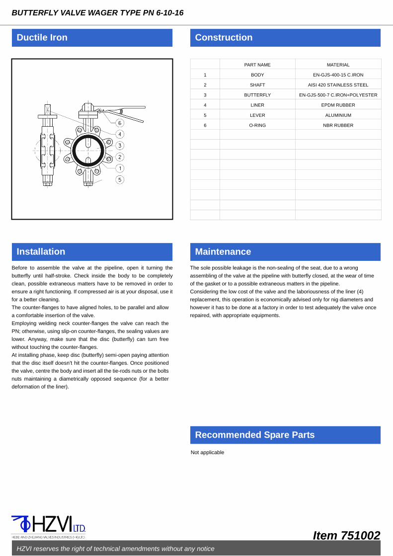
PART NAME MATERIAL
1 BODY EN-GJS-400-15 C.IRON
2 SHAFT AISI 420 STAINLESS STEEL
3 BUTTERFLY EN-GJS-500-7 C.IRON+POLYESTER
4 LINER EPDM RUBBER
5 LEVER ALUMINIUM
6
O-RING NBR RUBBER
Ductile Iron Construction
Installation Maintenance
Recommended Spare Parts
BUTTERFLY VALVE WAGER TYPE PN 6-10-16
Before to assemble the valve at the pipeline, open it turning the
butterfly until half-stroke. Check inside the body to be completely
clean, possible extraneous matters have to be removed in order to
ensure a right functioning. If compressed air is at your disposal, use it
for a better cleaning.
The counter-flanges to have aligned holes, to be parallel and allow
a comfortable insertion of the valve.
Employing welding neck counter-flanges the valve can reach the
PN; otherwise, using slip-on counter-flanges, the sealing values are
lower. Anyway, make sure that the disc (butterfly) can turn free
without touching the counter-flanges.
At installing phase, keep disc (butterfly) semi-open paying attention
that the disc itself doesn’t hit the counter-flanges. Once positioned
the valve, centre the body and insert all the tie-rods nuts or the bolts
nuts maintaining a diametrically opposed sequence (for a better
deformation of the liner).
The sole possible leakage is the non-sealing of the seat, due to a wrong
assembling of the valve at the pipeline with butterfly closed, at the wear of time
of the gasket or to a possible extraneous matters in the pipeline.
Considering the low cost of the valve and the laboriousness of the liner (4)
replacement, this operation is economically advised only for nig diameters and
however it has to be done at a factory in order to test adequately the valve once
repaired, with appropriate equipments.
Not applicable
HZVI reserves the right of technical amendments without any notice
Item 751002

Features
BUTTERFLY VALVE WAGER TYPE PN 6-10-16
Standard Execution
751002 Polyester coated nodular cast iron body and butterfly.
Stainless steel stem. Coated aluminium lever. EPDM liner.
Over DN 20 the valves are standard provided by gearbox.
Suitable to be assembled between flanges UNI NP 16-10.
Variations
751002/FI AISI 316 stainless steel butterfly
On Request
Bigger sizes flanged type
Nitrile liner suitable for gas (yellow lever)
EDPM liner suitable for drinking water
Gearbox with hand-wheel for sizes lower than DN 200
Pneumatic actuator S.A. or D.A.
Electric actuator
EPDM HT liner (max 130℃)
Different painting: i.e. fire-fighting colour (RAL 3000)
PN 16 execution from DN 250 to DN 500
Dimensions and Weights
Working Conditions
DN/ND L D H B F G V Kg Kv*
mm mm mm mm mm mm mm mm m³/h
40 33 82 205 139 4.5 26 205 2 131
50 43 103 227 154 4 27.5 205 3 204
65 46 121 246 160 10.2 48 205 3 204
80 46 132 260 170 16.8 65 205 4 522
100 52 155 295 187 24.2 86 205 5 816
125 56 190 324 205 33.8 112 250 7.5 1275
150 56 218 349 217 46.5 140 250 9 1835
200 60 273 442 257 69 191 400 13 3263
250 68 325 452 255 91 241 - 23 5099
300 78 375 522 28 111 290 - 30 7342
350 78 435 600 320 131 330 - 40 9994
400 102 485 658 339 144 376 - 57 13053
450 114 532 790 413 166 428 - 105 16520
500 127 587 840 448 181 457 - 127 20395
Opening angle 90∘
Size (mm) Allowable pressure(bar) Max working temperature related to
the pressure(C)
40-200 16 -10/+95
250-400 10 -10/+95
- Allowed picks until 110C
HZVI reserves the right of technical amendments without any notice
Item 751002

PART NAME MATERIAL
1 BODY EN GJS 400-18 DUCTILE IRON
2 SCREEN AISI304 ST.STEEL
3 SCREW 8.8 STEEL
4 COVER STEEL
5
GASKET GRAPHITE+STAINLESS
6 CENTR. RING STEEL
7
8
9
10
11
12
13
Ductile Iron Construction
Installation Maintenance
Recommended Spare Parts
SEDIMENT COLLECTING STRAINER PN 16
Before to assemble the strainer at the pipeline check inside the body
to be completely clean, possible extraneous matters have to be
removed in order to ensure a right filtering.
The strainer must be assembled following the direction indicated by
the arrow on the body, with flow direction down to up too.
The counter-flanges of the pipeline must be parallel and have
aligned holes. Check the space between them, keeping into
account the gaskets and their flattering after bolts closing (it should
not be too much or too litter) and face to face tolerances as per
EN-558-1 standard.
Fix the strainer in the right position at the pipeline and remember to
insert the gaskets between the flanges centering them as much as
possible on the raised faces.
The raised faces have to be clean to allow a correct tightness.
Fit the bolts in flanges holes and tighten them maintaining a
diametrically opposed sequence (for a better deformation of the
gaskets).
The strainer is normally assembled at pipelines in order to avoid the impurities
to damage the equipment installed below, that is on/off valves, regulating
valves, etc.
The screen (2) has to be periodically cleaned. To carry out this operation:
loosen the body/cover screws (3), take off the cover (4),clean the screen.
Before to assemble it again, check if the sealing areas are carefully cleaned
and not damaged; check if each part of the gasket is integral, otherwise it is
recommended to replace it. If necessary the strainer can be completely
disassembled using standard tools.
Screen (2) – Gasket (5)
HZVI reserves the right of technical amendments without any notice
Item 751101
ON REQUEST

Features
SEDIMENT COLLECTING STRAINER PN 16
Standard Execution
751101 Ductile iron body. Carbon steel Cover. Stainless steel screen. Connection flanges dressed and drilled according to EN 1092-2 PN 16 standards with raised face.
On Request
Flanges with special drillings Drain plug on the cover Screen with different kinds of drilling AISI 316 stainless steel screen Cock with tube holder for easy drain
Dimensions and Weights
Working Conditions
DN D L H Kg Kv
mm mm mm mm m³/h
15 95 130 73 2.3 4.9
20 105 150 73 3.1 7.8
25 115 160 78 4.1 10.1
32 140 180 90 5.5 14.4
40 150 200 105 7.8 22.5
50 165 230 113 9.6 30.7
65 185 290 143 18 58.7
80 200 310 150 20.5 78.5
100 220 350 165 26.5 117
125 250 400 185 40 195
150 285 480 205 56 249
200 340 600 245 99 320
250 405 730 313 167 785
300 460 850 355 242 1059
Size (mm) Allowable pressure (bar) Max working temperature related to the pressure(C)
15-300 16 -10/+120
15-300 14.7 +200
15-300 13.9 +250
15-300 12.8 +300
HZVI reserves the right of technical amendments without any notice
Item 751101

PART NAME MATERIAL
1 BODY EN GJS 400-18 LT C.IRON
2 SCREEN AISI304 ST.STEEL
3 SCREW 8.8 STEEL
4 COVER STEEL
5
GASKET GRAPHITE+STAINLESS
6 CENTR. RING STEEL
7
8
9
10
11
12
13
14
]
Ductile Iron Construction
Installation Maintenance
Recommended Spare Parts
SEDIMENT COLLECTING STRAINER PN 25
Before to assemble the strainer at the pipeline check inside the body
to be completely clean, possible extraneous matters have to be
removed in order to ensure a right filtering.
The strainer must be assembled following the direction indicated by
the arrow on the body, with flow direction down to up too.
The counter-flanges of the pipeline must be parallel and have
aligned holes. Check the space between them, keeping into
account the gaskets and their flattering after bolts closing(it should
not be too much or too litter) and face to face tolerances as per
EN-558-1 standard.
Fix the strainer in the right position at the pipeline and remember to
insert the gaskets between the flanges centering them as much as
possible on the raised faces.
The raised faces have to be clean to allow a correct tightness.
Fit the bolts in flanges holes and tighten them maintaining a
diametrically opposed sequence (for a better deformation of the
gaskets).
The strainer is normally assembled at pipelines in order to avoid the impurities
to damage the equipment installed below, that is on/off valves, regulating
valves, etc.
The screen (2) has to be periodically cleaned. To carry out this operation:
loosen the body/cover screws (3), take off the cover (4), clean the screen.
Before to assemble it again, check if the sealing areas are carefully cleaned
and not damaged; check if each part of the gasket is integral, otherwise it is
recommended to replace it. If necessary the strainer can be completely
disassembled using standard tools.
Screen (2) – Gasket (5)
HZVI reserves the right of technical amendments without any notice
Item 751102
ON REQUEST
Features
SEDIMENT COLLECTING STRAINER PN 25
Standard Execution
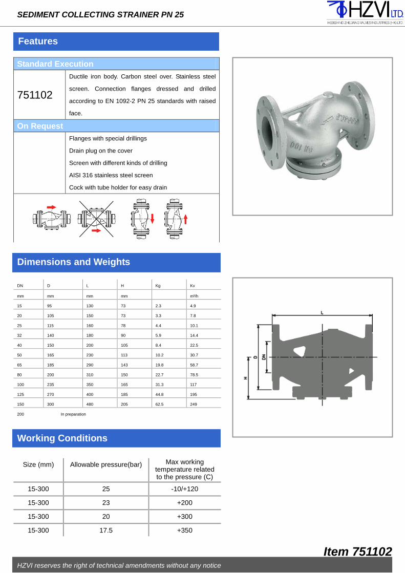
751102
Ductile iron body. Carbon steel over. Stainless steel
screen. Connection flanges dressed and drilled
according to EN 1092-2 PN 25 standards with raised
face.
On Request
Flanges with special drillings
Drain plug on the cover
Screen with different kinds of drilling
AISI 316 stainless steel screen
Cock with tube holder for easy drain
Dimensions and Weights
Working Conditions
DN D L H Kg Kv
mm mm mm mm m³/h
15 95 130 73 2.3 4.9
20 105 150 73 3.3 7.8
25 115 160 78 4.4 10.1
32 140 180 90 5.9 14.4
40 150 200 105 8.4 22.5
50 165 230 113 10.2 30.7
65 185 290 143 19.8 58.7
80 200 310 150 22.7 78.5
100 235 350 165 31.3 117
125 270 400 185 44.8 195
150 300 480 205 62.5 249
200 In preparation
Size (mm) Allowable pressure(bar) Max working temperature related to the pressure (C)
15-300 25 -10/+120
15-300 23 +200
15-300 20 +300
15-300 17.5 +350
HZVI reserves the right of technical amendments without any notice
Item 751102
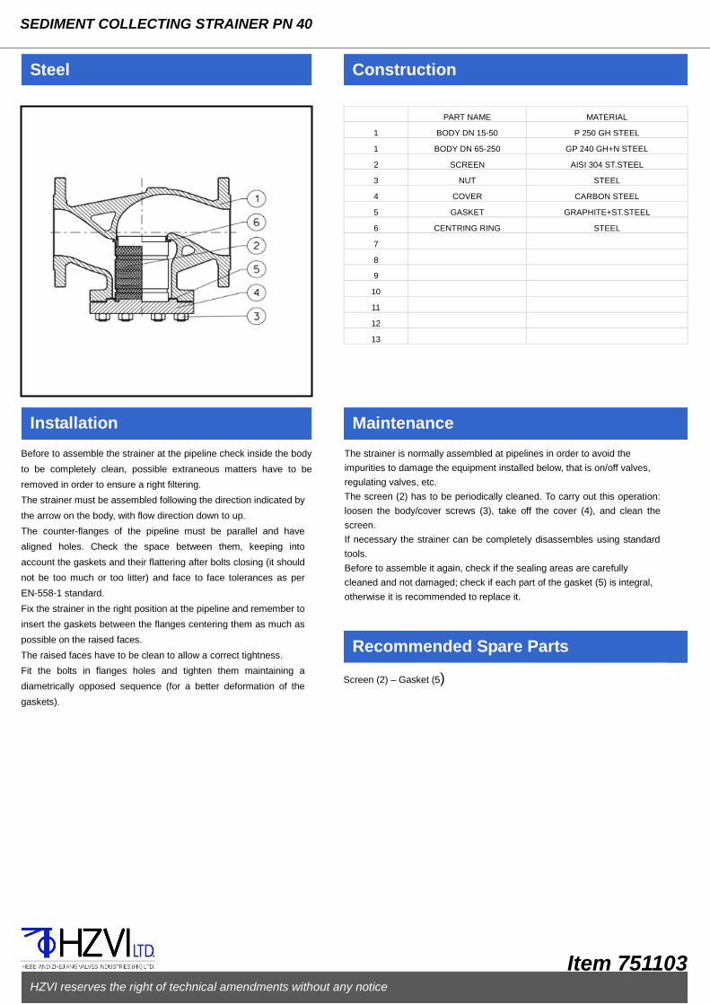
PART NAME MATERIAL
1 BODY DN 15-50 P 250 GH STEEL
1 BODY DN 65-250 GP 240 GH+N STEEL
2
SCREEN AISI 304 ST.STEEL
3 NUT STEEL
4
COVER CARBON STEEL
5 GASKET GRAPHITE+ST.STEEL
6 CENTRING RING STEEL
7
8
9
10
11
12
13
Steel Construction
Installation Maintenance
Recommended Spare Parts
SEDIMENT COLLECTING STRAINER PN 40
Before to assemble the strainer at the pipeline check inside the body
to be completely clean, possible extraneous matters have to be
removed in order to ensure a right filtering.
The strainer must be assembled following the direction indicated by
the arrow on the body, with flow direction down to up.
The counter-flanges of the pipeline must be parallel and have
aligned holes. Check the space between them, keeping into
account the gaskets and their flattering after bolts closing (it should
not be too much or too litter) and face to face tolerances as per
EN-558-1 standard.
Fix the strainer in the right position at the pipeline and remember to
insert the gaskets between the flanges centering them as much as
possible on the raised faces.
The raised faces have to be clean to allow a correct tightness.
Fit the bolts in flanges holes and tighten them maintaining a
diametrically opposed sequence (for a better deformation of the
gaskets).
The strainer is normally assembled at pipelines in order to avoid the
impurities to damage the equipment installed below, that is on/off valves,
regulating valves, etc.
The screen (2) has to be periodically cleaned. To carry out this operation:
loosen the body/cover screws (3), take off the cover (4), and clean the
screen.
If necessary the strainer can be completely disassembles using standard
tools.
Before to assemble it again, check if the sealing areas are carefully
cleaned and not damaged; check if each part of the gasket (5) is integral,
otherwise it is recommended to replace it.
Screen (2) – Gasket (5)
HZVI reserves the right of technical amendments without any notice
Item 751103

Features
SEDIMENT COLLECTING STRAINER PN 40
Standard Execution
751103 Carbon steel body and bonnet. Stainless steel screen. Asbestos free gasket. Connection flanges dressed and drilled according to EN 1092 PN 40 with raised face.
Variations
751103 GX5CrNiMo 19-11-2 stainless steel.
On Request
Flanges with special drillings Drain plug on the cover Screen with different kinds of drilling AISI 316 stainless steel screen BW or SW connections Cock with tube holder for easy drain
Dimensions and Weights
Working Conditions
DN D L H Kg Kv
mm mm mm mm m³/h
15 95 130 84 3 5.1
20 105 150 88 3.5 8
25 115 160 93 4.5 10.5
32 140 180 96 6.5 15
40 150 200 108 8.4 23.4
50 165 230 120 10.2 31.9
65 185 290 191 19.5 64
80 200 310 200 22 81.6
100 235 350 215 38 122
125 270 400 236 57 203
150 300 480 250 74 259
200 375 600 305 123 333
250 On request
Size (mm) Allowable pressure (bar) Max working temperature related to the pressure(C)
15-200 40 -10/+50
15-200 37.3 +100
15-200 25.8 +300
15-200 23.1 +400
HZVI reserves the right of technical amendments without any notice
Item 751103

PART NAME MATERIAL
1 BODY EN-GJL-250 CAST IRON
2
SCREEN AISI 304 ST.STEEL
3 GASKET GRAPHITE+ST.STEEL
4
COVER EN-GKL-250 CAST IRON
5 NUT STEEL
6 SCREW STEEL
7 DRAIN PLUG STEEL
8
9
10
11
12
13
14
Ductile Iron Construction
Installation Maintenance
Recommended Spare Parts
“Y” STRAINER PN 16
Before to assemble the strainer at the pipeline check inside the body
to be completely clean, possible extraneous matters have to be
removed in order to ensure a right filtering.
The strainer must be assembled following the direction indicated by
the arrow on the body, with flow direction down to up.
The counter-flanges of the pipeline must be parallel and have
aligned holes. Check the space between them, keeping into
account the gaskets and their flattering after bolts closing (it should
not be too much or too litter) and face to face tolerances as per
EN-558-1 standard.
Fix the strainer in the right position at the pipeline and remember to
insert the gaskets between the flanges centering them as much as
possible on the raised faces.
The raised faces have to be clean to allow a correct tightness.
Fit the bolts in flanges holes and tighten them maintaining a
diametrically opposed sequence (for a better deformation of the
gaskets).
The strainer is normally assembled at pipelines in order to avoid the impurities
to damage the equipment installed below, which is on/off valves, regulating
valves, etc.
The screen (2) has to be periodically cleaned.
To carry out this operation: loosen the body/cover screw (6), take off the cover
(4), clean the screen. Before to assemble it again, check if the sealing areas
are carefully cleaned and not damaged; check if each part of the gasket (6) is
integral, otherwise it is recommended to replace it. If necessary the strainer can be completely disassembles using standard
tools.
The threaded plug on the cover, standard provided for strainers from DN 50
up, is useful to discharge the fluid that remains in the strainers.
It is possible to assemble a drain cock instead of the plug, in order to make
easier the draining of the strainer (see pic.1). THIS COCK WILL BE MADE
OF A MATERIAL SUITABLE TO THE FLUID, WORKING PRESSURE AND
TEMPERATURE.
Screen (2) – Gasket (3)
HZVI reserves the right of technical amendments without any notice
Item 751202
ON REQUEST

Features
“Y” STRAINER PN 16
Standard Execution
751202 Ductile iron body. Carbon steel over. Stainless steel screen. Connection flanges dressed and drilled according to EN 1092-2 PN 16 standards with raised face. Drain plug on the cover from DN 65 up.
Variations
751202/25 PN 25 execution
On Request
Bigger sizes Flanges with special drillings Drain plug on the cover for DN<65 Screen with different kinds of drilling AISI 316 stainless steel screen Cock with tube holder for easy drain
Dimensions and Weights
Working Conditions
DN D PN16 D PN25 L H Kg PN 16 Kg PN25 Kv
mm mm Mm mm mm m³/h
15 95 95 130 75 2.6 2.6 5.3
20 105 105 150 75 3.4 3.4 9.5
25 115 115 160 90 4 4 16.5
32 140 140 180 90 5.8 5.8 20
40 150 150 200 110 7.2 7.2 33
50 165 165 230 120 9.6 9.6 54
65 185 185 290 140 13.6 13.2 95
80 200 200 310 165 17 17.8 140
100 220 235 350 220 27.6 29 201
125 250 270 400 260 37.2 39.6 340
150 285 300 480 300 56.6 58.6 526
200 340 360 600 360 124 128 870
250 405 425 730 470 160.8 168 1260
300 460 485 850 560 189 195 1735
Size (mm) Allowable pressure (bar) Max working temperature related to
the pressure(C)
15-300 (PN16) 16 -10/+120
15-300 (PN16) 13.9 +250
15-300 (PN16) 11.2 +350
15-300 (PN25) 25 -10/+120
15-300 (PN25) 21.8 +250
15-300 (PN25) 17.5 +350
HZVI reserves the right of technical amendments without any notice
Item 751202

PART NAME MATERIAL
1 BODY EN-GJS-400-15 CAST IRON
2 STEM STAINLESS STEEL
3 BONNET EN-GJS-400-15 CAST IRON
4 WEDGE DUCTILE IRON VULC.NBR
5
MOTHERSCREW BRASS
6 GASKET RUBBER
7 LOWER BUSH BRONZE
8 UPPER BUSH BRONZE
9 DUST COVER RUBBER
10 HAND-WHEEL PRESSED STEEL
11 SCREW ZINC PLATED STEEL
12 PROTECTION CAP RESIN
13 BOLTS ZINC PLATED STEEL
14 O-RING NBR
Ductile Iron Construction
Installation Maintenance
Recommended Spare Parts
FLAT BODY GATE VALVE - INTERNAL SCREW PN16 - MAINTENANCE FREE
Before to assemble the gate valve at the pipeline, open it until about
half-stroke. Check inside the body to be completely clean, possible
extraneous matters have to be removed in order to ensure a right
functioning. If compressed air is at your disposal, use it for a better
cleaning.
The counter-flanges of the pipeline must be parallel and have
aligned holes. Check the space between them, keeping into
account the gaskets and their flattering after bolts closing (it should
not be too much or too litter) and face to face tolerances as per
EN-558-1 standard.
Fix the gate valve in the right position at the pipeline and remember
to insert the gaskets between the flanges centering them as much
as possible on the raised faces.
The raised faces have to be clean to allow a correct tightness.
Fit the bolts in flanges holes and tighten them maintaining a
diametrically opposed sequence (for a better deformation of the
gaskets).Check the right functioning of the gate valve with two or
three complete open-close operations.
THE GATE VALVE NEEDS NO MAINTENANCE.
The sole possible leakage is the one from O-rings(14) due to their accidental
breaking or wear (12) and loosening the bolts (13), take off the hand wheel
(10) loosening its stop screw (15), loosen the lower bush (7), take off the stem
(2) and the upper bush (8); only after you have checked the integrity of or
housing, stem and bonnet, you can replace all the O-rings and assemble
again the gate valve.
If the gate valve should leak from the seat, do not insist in closing with more
strength by the hand wheel and do not use levers because it is possible to
damage more the sealing seats; in this case open and close again the valve
in order to remove possible sediments.
If necessary the gate valve can be completely disassembled using standard
tools.
Before to assemble it again, open the valve at two hand wheel turns, check if
the sealing seats are carefully clean and not damaged; check if each part of
the gasket is integral, otherwise it is recommended to replace it.
Lower bush (7) and upper bush (8) complete with O-rings (14), only if stem and
bonnet are not worn out.
HZVI reserves the right of technical amendments without any notice
Item 751301

Features
FLAT BODY GATE VALVE - INTERNAL SCREW PN 16 - MAINTENANCE FREE
Standard Execution
881301
Ductile iron body and bonnet. Stainless steel stem. Ductile iron wedge NBR vulcanized. Pressed steel hand wheel. Full bore, minimal pressure drop, absolute tightness, wedge with anti-freezing drain, clockwise closing. Inside and outside epoxy coating min. thickness 150 microns. Connection flanges dressed and drilled according to EN 1092-2 PN 16 with raised face.
On Request
Bigger sizes Flanges with special drillings Gaskets suitable for temperature over 70℃ Chain-wheel for remote maneuver With gearbox – with electric actuator Micro-switches Position indicator Padlock device
Dimensions and Weights
Working Conditions
DN D L H V Kg Kv
mm mm mm mm mm m³/h
40 150 140 230 250 9 140
50 165 150 260 250 12 190
65 185 170 270 250 15 370
80 200 180 310 250 17 240
100 220 190 340 250 26 930
125 250 200 405 350 38 1650
150 285 210 460 350 47 2650
200 340 230 570 350 82 5500
250 405 250 660 500 130 8900
300 460 270 770 500 175 13800
Size (mm) Allowable pressure (bar) Max working temperature related to the pressure(C)
40-300 16 -10/+70
HZVI reserves the right of technical amendments without any notice
Item 751301

PART NAME MATERIAL
1 BODY EN-GJS-400-15 CAST IRON
2 STEM STAINLESS STEEL
3 BONNET EN-GJS-400-15 CAST IRON
4 WEDGE DUCTILE IRON VULC.NBR
5
MOTHERSCREW BRASS
6 GASKET RUBBER
7 LOWER BUSH BRONZE
8 UPPER BUSH BRONZE
9 DUST COVER RUBBER
10 HANDWHEEL PRESSED STEEL
11 SCREW ZINC PLATED STEEL
12 PROTECTION CAP RESIN
13 BOLTS ZINC PLATED STEEL
14 O-RING NBR
Ductile Iron Construction
Installation Maintenance
Recommended Spare Parts
OVAL BODY GATE VALVE - INTERNAL SCREW PN16 - MAINTENANCE FREE
Before to assemble the gate valve at the pipeline, open it until
about half-stroke. Check inside the body to be completely clean,
possible extraneous matters have to be removed in order to ensure
a right functioning. If compressed air is at your disposal, use it for a
better cleaning.
The counter-flanges of the pipeline must be parallel and have
aligned holes. Check the space between them, keeping into
account the gaskets and their flattering after bolts closing (it should
not be too much or too litter) and face to face tolerances as per
EN-558-1 standard.
Fix the gate valve in the right position at the pipeline and remember
to insert the gaskets between the flanges centering them as much
as possible on the raised faces.
The raised faces have to be clean to allow a correct tightness.
Fit the bolts in flanges holes and tighten them maintaining a
diametrically opposed sequence (for a better deformation of the
gaskets).Check the right functioning of the gate valve with two or
three complete open-close operations.
THE GATE VALVE NEEDS NO MAINTENANCE.
The sole possible leakage is the one from O-rings (14) due to their accidental
breaking or wear of time; in this case, to replace them, disassemble the
bonnet (3) taking off the protection caps(12) and loosening the bolts (13), take
off the hand-wheel (10) loosening its stop screw (15), loosen the lower bush
(7), take off the stem (2) and the upper bush (8); only after you have checked
the integrity of OR housing, stem and bonnet, you can replace all the O-rings
and assemble again the gate valve.
If the gate valve should leak from the seat, do not insist in closing with more
strength by the hand-wheel and do not use levers because it is possible to
damage more the sealing seats; in this case open and close again the valve
in order to remove possible sediments.
If necessary the gate valve can be completely disassembled using standard
tools.
Before to assemble it again, open the valve at two hand-wheel turns, check if
the sealing seats are carefully clean and not damaged; check if each part of
the gasket is integral, otherwise it is recommended to replace it.
Lower bush (7) and upper bush (8) complete with O-rings (14), only if stem and
bonnet are not worn out.
HZVI reserves the right of technical amendments without any notice
Item 751303

Features
OVAL BODY GATE VALVE - INNTERNAL SCREW PN - 16MAINTENANCE FREE
Standard Execution
751303
Ductile iron body and bonnet. Stainless steel stem. Ductile iron iron wedge NBR vulcanized. Pressed steel hand-wheel. Full bore, minimal pressure drop, absolute tightness, wedge with anti-freezing drain, clockwise closing. Inside and outside epoxy coating min. thickness 150 microns. Connection flanges dressed and drilled according to EN 1092-2 PN 16 with raised face.
On Request
Bigger sizes Flanges with special drillings Gaskets suitable for temperature over 70℃ Chain-wheel for remote maneuver With gearbox – with electric actuator Micro switches Position indicator Padlock device
Dimensions and Weights
Working Conditions
DN D L H V Kg Kv
mm mm mm mm mm m³/h
40 150 240 230 250 10 140
50 165 250 260 250 13 190
65 185 270 270 250 18 370
80 200 280 310 250 20 240
100 220 300 340 250 28 930
125 250 325 405 350 41 1650
150 285 350 460 350 51 2650
200 340 400 570 350 93 5500
250 405 450 660 500 148 8900
300 460 500 770 500 109 13800
Size (mm) Allowable pressure (bar) Max working temperature related to the pressure(C)
40-300 16 -10/+70
HZVI reserves the right of technical amendments without any notice
Item 751303

PART NAME MATERIAL
1 BODY EN-GJS-400-18-LT DUCTILE IRON
2 SEAT DN 15-250 STAINLESS STEEL
2 SEAT DN 300 STEEL+ST.STEEL
3 STEM STAINLESS STEEL
4 DISC DN 15-100 STAINLESS STEEL
4 DISC DN 125-250 STEEL+ST.STEEL
5
YOKE EN-GJS-400-18-LT DUCTILE IRON
6 BELLOWS STAINLESS STEEL
7 GASKETS GRAPHITE+ST.STEEL
8 PACKING CARBO-GRAPHITE
9 GLAND ZINC PLATED STEEL
10 STEM GUIDE-INDEX CARBON STEEL
11 BUSH ZINC PLATED STEEL
12 ANTIFRICTION BEARINGS TEMPERED STEEL IRON
13 HAND-WHEEL STEEL
14 STOP HANDWHEEL NUT CARBON STEEL
15 BLANK NUT CARBON STEEL
16 ANTI-FRICTION DISK STAINLESS STEEL
17 ELASTIC PIN CARBON STEEL
18 SCREWS STEEL 8.8
19 ELASTIC RING STAINLESS STEEL
20 LUBRICATOR ZINC PLATED STEEL
21 STOP SCREW ZINC PLATED STEEL
22 RISE LIMITER SCREW ZINC PLATED STEEL
Ductile Iron Construction
Installation Maintenance
Recommended Spare Parts
STREAMLINED FLOW VALVE WITH BELLOWS - EXTERNAL SCREW PN 16 - MAINTENANCE FREE
Before to assemble the valve at the pipeline, open it until about
half-stroke. Check inside the body to be completely clean, possible
extraneous matters have to be removed in order to ensure a right
functioning. If compressed air is at your disposal, use it for a better
cleaning.
The counter-flanges of the pipeline must be parallel and have
aligned holes. Check the space between them, keeping into
account the gaskets and their flattering after bolts closing (it should
not be too much or too litter) and face to face tolerances as per
EN-558-1 standard.
The valve must be assembled following the direction indicated by
the arrow on the body. Fix the valve in the right position at the
pipeline and remember to insert the gaskets between the flanges
centering them as much as possible on the raised face.
The raised faces have to be clean to allow a correct tightness.
Fit the bolts in flanges holes and tighten them maintaining a
diametrically opposed sequence (for a better deformation of the
gaskets).Check the right functioning of the gate valve with two or
three complete open-close operations.
THIS KIND OF VALVE NEEDS NO MAINTENANCE SINCE THE BELLOWS
HAS BEEN TESTED FOR THOUSANDS MANOEUVRES.
The leakage of fluid from the stuffing box indicate the accidental breaking of the
bellows (6). Waiting to repair or replace the valve, tighten the gland(9).
In order to add more packing when plant not in pressure neither temperature,
unscrew the gland (9), fit new packing and tighten it again.
Using the backseat it is possible to add more packing when the plant is working,
unfasten completely the locking set screw(21) and the rise limiter(22) (if proved),
use the backseat on the stem forcing the opening maneuver, check its
functionality and act following the above mentioned operations. This must be
carried out within a short term from the bellows breaking since the fluid could
damage the functionality of the backseat.
If necessary the valve can be completely disassembled using standard tools.
It is economically advisable to repair the valve only for big sizes.
Before to assemble it again, open the valve at two hand-wheel turns, check if the
sealing seats are carefully clean and not damaged; check if each part of the
gaskets(7-8) is integral, otherwise it is recommended to replace them.
Functioning instructions are supplied together with each valve.
Packing (8) – Gaskets (7) – Complete kit: stem/bellows/disc (3-6-4)
HZVI reserves the right of technical amendments without any notice
Item 751401

Features
STREAMLINED FLOW VALVE WITH BELLOWS - EXTERNAL SCREW PN 16 - MAINTENANCE FREE
Standard Execution
751401
Ductile iron body and yoke. Stainless steel stem, bellows
and sealing seats. Graphite + stainless steel gaskets.
Carbon steel hand-wheel. The valve is standard provided
by: position indicator, safety backseat on the stem, rise
limiter, lubricator, locking set screw. Connection flanges
dressed and drilled according to EN 1092-1 PN 16 with
raised face.
Variations
751401/R Parabolic
disc 751401/E
Balanced disc
751401/T Interchangeable PTFE gasket on the disc(max 180℃)
751401/A SDNR disc(check + on/off function)
751401/RT Parabolic disc with interchangeable PTFE gasket(max
180℃)
On Request
Bigger sizes
Flanges with special drillings
Chain-wheel for remote maneuver
Pneumatic actuator S.A. or D.A. – electric actuator with
fittings
Padlock device
Stellite overlay on seat and disc
Dimensions and Weights
Working Conditions
DN D L H V Kg Kv
mm mm mm mm Mm m³/h
15 95 130 234 125 3.8 4.6
20 105 150 243 125 4.4 7.3
25 115 160 253 125 5.3 11.7
32 140 180 242 125 6.8 16.8
40 150 200 275 150 9 26.7
50 165 230 276 150 11.3 42.6
65 185 290 377 200 21 77.9
80 200 310 378 200 24 111
100 220 350 401 250 31 177
125 250 400 442 300 45.5 262
150 285 480 494 350 65 368
200 340 600 620 400 117.5 664
250 405 730 748 500 180 1044
300 460 850 770 600 247.6 1493
Size (mm) Allowable pressure (bar) Max working temperature related to the pressure(C)
15-300 16 -10/+120
15-300 14.7 +200
15-300 13.9 +250
15-300 12.8 +300
15-300 11.2 +350
HZVI reserves the right of technical amendments without any notice
Item 751401

PART NAME MATERIAL
1 BODY EN-GJL-400-18-LT C.IRON
2 SEAT RING STAINLESS STEEL
3 STEM STAINLESS STEEL
4 DISC DN 15-100 STAINLESS STEEL
4 DISC DN 125-250 STEEL+ST.STEEL
5
YOKE EN-GJL-400-18-LT C.IRON
6 BELLOWS STAINLESS STEEL
7 GASKETS GRAPHITE+ST.STEEL
8 PACKING CARBO-GRAPHITE
9 GLAND ZINC PLATED STEEL
10 STEM GUIDE-INDEX CARBON STEEL
11 BUSH CARBON STEEL
12 ANTIFRICTION BEARINGS TEMPERED STEEL IRON
13 HAND-WHEEL STEEL
14 STOP HANDWHEEL NUT CARBON STEEL
15 BLANK NUT CARBON STEEL
16 ANTI-FRICTION DISK STAINLESS STEEL
17 ELASTIC PIN CARBON STEEL
18 SCREWS STEEL 8.8
19 ELASTIC RING STAINLESS STEEL
20 LUBRICATOR ZINC PLATED STEEL
21 STOP SCREW ZINC PLATED STEEL
22 RISE LIMITER SCREW ZINC PLATED STEEL
Ductile Iron Construction
Installation Maintenance
Recommended Spare Parts
STREAMLINED FLOW VALVE WITH BELLOWS - EXTERNAL SCREW PN 25 - MAINTENANCE FREE
Before to assemble the valve at the pipeline, open it until about
half-stroke. Check inside the body to be completely clean, possible
extraneous matters have to be removed in order to ensure a right
functioning. If compressed air is at your disposal, use it for a better
cleaning.
The counter-flanges of the pipeline must be parallel and have
aligned holes. Check the space between them, keeping into
account the gaskets and their flattering after bolts closing (it should
not be too much or too litter) and face to face tolerances as per
EN-558-1 standard.
The valve must be assembled following the direction indicated by
the arrow on the body. Fix the valve in the right position at the
pipeline and remember to insert the gaskets between the flanges
centring them as much as possible on the raised face.
The raised faces have to be clean to allow a correct tightness.
Fit the bolts in flanges holes and tighten them maintaining a
diametrically opposed sequence (for a better deformation of the
gaskets).Check the right functioning of the gate valve with two or
three complete open-close operations.
THIS KIND OF VALVE NEEDS NO MAINTENANCE SINCE THE BELLOWS
HAS BEEN TESTED FOR THOUSANDS MANOEUVRES.
The leakage of fluid from the stuffing box indicate the accidental breaking of the
bellows (6). Waiting to repair or replace the valve, tighten the gland (9).
In order to add more packing when plant not in pressure neither temperature,
unscrew the gland (9), fit new packing and tighten it again.
Using the backseat it is possible to add more packing when the plant is working,
untighten completely the locking set screw(21) and the rise limiter(22) (if
proved), use the backseat on the stem forcing the opening maneuver, check its
functionality and act following the above mentioned operations. This must be
carried out within a short term from the bellows breaking since the fluid could
damage the functionality of the backseat.
If necessary the valve can be completely disassembled using standard tools.
It is economically advisable to repair the valve only for big sizes.
Before to assemble it again, open the valve at two handwheel turns, check if the
sealing seats are carefully clean and not damaged; check if each part of the
gaskets(7-8) is integral, otherwise it is recommended to replace them.
Functioning instructions are supplied together with each valve.
Packing (8) – Gaskets (7) – Complete kit: stem/bellows/disc (3-6-4)
HZVI reserves the right of technical amendments without any notice
Item 751402

Features
STREAMLINED FLOW VALVE WITH BELLOWS - EXTERNAL SCREW PN 25 - MAINTENANCE FREE
Standard Execution
751402
Ductile iron body and yoke. Stainless steel stem, bellows
and sealing seats. Graphite + stainless steel gaskets.
Carbon steel hand-wheel. The valve is standard provided
by: position indicator, safety backseat on the stem, rise
limiter, lubricator, locking set screw. Connection flanges
dressed and drilled according to EN 1092-1 PN 25 with
raised face.
Variations
751402/R Parabolic
disc 751402/E
Balanced disc
751402/T Interchangeable PTFE gasket on the disc(max 180℃)
751402/A SDNR disc(check + on/off function)
751402/RT Parabolic disc with interchangeable PTFE gasket(max
180℃)
On Request
Bigger sizes
Flanges with special drillings
Chain-wheel for remote maneuver
Pneumatic actuator S.A. or D.A. – electric actuator with
fittings
Padlock device
Stellite overlay on seat and disc
Dimensions and Weights
Working Conditions
DN D L H V Kg Kv
mm mm mm mm Mm m³/h
15 95 130 234 125 3.8 4.6
20 105 150 243 125 4.4 7.3
25 115 160 253 125 5.3 11.7
32 140 180 242 125 6.8 16.8
40 150 200 275 150 9 26.7
50 165 230 276 150 11.3 42.6
65 185 290 377 200 21 77.9
80 200 310 378 200 24 111
100 220 350 401 250 31 177
125 250 400 442 300 45.5 262
150 285 480 494 350 65 368
200 In preparation
Size (mm) Allowable pressure (bar) Max working temperature related to the pressure(C)
15-150 25 -10/+120
15-150 23 +200
15-150 21.8 +250
15-150 20 +300
15-150 17.5 +350
HZVI reserves the right of technical amendments without any notice
Item 751402

PART NAME MATERIAL
1 BODY EN-GJS-400-18LT C.IRON
2 SEAT STAINLESS STEEL
3 STEM STAINLESS STEEL
4 DISC DN 15-100 STAINLESS STEEL
4 DISC DN 125-250 STEEL+ST.STEEL
5
BONNET EN-GJS-400-18-LTC C.IRON
6 BELLOWS STAINLESS STEEL
7 GASKETS GRAPHITE+ST.STEEL
8 PACKING CARBON-GRAPHITE
9 GLAND ZINC PLATED STEEL
10 BOTTOM RING ZINC PLATED STEEL
11 ANTIFRICTION BEARINGS STAINLESS STEEL
12 ELASTIC RING STAINLESS STEEL
13 HAND-WHEEL STEEL
14 NUT ZINC PLATED STEEL
15 INDENTIFICATION PLATE ALUMINIUM
16 WASHER STEEL
17 SCREWS STEEL 8.8
Ductile Iron Construction
Installation Maintenance
Recommended Spare Parts
STREAMLINED FLOW VALVE WITH BELLOWS – INTERNAL SCREW PN 16 - MAINTENANCE FREE
Before to assemble the valve at the pipeline, open it until about
half-stroke. Check inside the body to be completely clean, possible
extraneous matters have to be removed in order to ensure a right
functioning. If compressed air is at your disposal, use it for a better
cleaning.
The counter-flanges of the pipeline must be parallel and have
aligned holes. Check the space between them, keeping into
account the gaskets and their flattering after bolts closing(it should
not be too much or too litter) and face to face tolerances as per
EN-558-1 standard.
The valve must be assembled following the direction indicated by
the arrow on the body. Fix the valve in the right position at the
pipeline and remember to insert the gaskets between the flanges
centring them as much as possible on the raised face.
The raised faces have to be clean to allow a correct tightness.
Fit the bolts in flanges holes and tighten them maintaining a
diametrically opposed sequence (for a better deformation of the
gaskets).Check the right functioning of the gate valve with two or
three complete open-close operations.
THIS KIND OF VALVE NEEDS NO MAINTENANCE SINCE THE BELLOWS
HAS BEEN TESTED FOR THOUSANDS MANOEUVRES.
The sole possible leakage is the on due to the accidental breaking of the bellows
(6), noticeable by the fluid loss from the stuffing box. This anomaly is due to the
wear (of time) or to water-hammer or to extraneous matters in the pipeline.
Waiting to repair to replace the valve, tighten the gland (9) in order to reduce the
leakage.
It is possible to repair the valve (economically advisable only for the big sizes) as
long as bonnet threading (5) is not too much worn; unscrew the screws (17) and
disassemble the bonnet from the body, take off stem/bellow/disc and replace
them with a new kit.
If the valve should leak from the seat, do not insist in closing with more strength
by the hand-wheel and do not use levers because it is possible to damage more
the sealing seats; in this case open and close again the valve in order to remove
possible sediments.
If necessary the valve can be completely disassembled using standard tools.
Before to assemble it again, open the valve at two hand-wheel turns, check if the
sealing seats are carefully clean and not damaged; check if each part of the
gaskets(7-8) is integral, otherwise it is recommended to replace them.
Packing (8) – Gaskets (7) – Complete kit: stem/bellows/disc (3-6-4)
HZVI reserves the right of technical amendments without any notice
Item 751403

Features
STREAMLINED FLOW VALVE WITH BELLOWS – INTERNAL SCREW PN 16 - MAINTENANCE FREE
Standard Execution
751403 Ductile iron body and bonnet. Stainless steel stem, bellows
and sealing seats. Graphite + stainless steel gaskets.
Carbon steel hand-wheel. Connection flanges dressed and
drilled according to EN 1092-2 PN 16 with raised face.
Variations
751403/R Parabolic disc
751403/T Interchangeable PTFE gasket on the disc(max 180℃)
On Request
Bigger sizes
Flanges with special drillings
Chain-wheel for remote maneuver
Pneumatic actuator S.A. or D.A. – electric actuator with
fittings
Padlock device
Stellite overlay on seat and disc
Dimensions and Weights
Working Conditions
DN D L H H' V Kg Kv
mm mm mm mm Mm Mm m³/h
15 95 130 167 175 100 3 4.6
20 105 150 167 175 100 3.8 7.3
25 115 160 183 191 100 4.9 11.7
32 140 180 183 193 125 6.4 16.8
40 150 200 216 229 150 9 26.7
50 165 230 216 231 150 11.4 42.6
65 185 290 293 314 200 19 77.9
80 200 310 293 316 200 22 111
100 220 350 321 353 225 31 177
125 250 400 345 385 250 45 262
150 285 480 398 443 350 64 368
200 340 600 455 517 400 112 664
250 405 730 585 660 500 177 1044
Size (mm) Allowable pressure(bar) Max working temperature related to
the pressure(C)
15-250 16 -10/+120
15-250 14.7 +200
15-250 13.9 +250
15-250 12.8 +300
15-250 11.2 +350
HZVI reserves the right of technical amendments without any notice
Item 751403

PART NAME MATERIAL
1 BODY EN-GJS-400-18LT C.IRON
2 SEAT STAINLESS STEEL
3 STEM STAINLESS STEEL
4 DISC DN 15-100 STAINLESS STEEL
4 DISC DN 125-250 STEEL+ST.STEEL
5
BONNET EN-GJS-400-18-LTC C.IRON
6 BELLOWS STAINLESS STEEL
7 GASKETS GRAPHITE+ST.STEEL
8 PACKING CARBON-GRAPHITE
9 GLAND ZINC PLATED STEEL
10 BOTTOM RING ZINC PLATED STEEL
11 ANTIFRICTION BEARINGS STAINLESS STEEL
12 ELASTIC RING STAINLESS STEEL
13 HAND-WHEEL STEEL
14 NUT ZINC PLATED STEEL
15 INDENTIFICATION PLATE ALUMINIUM
16 WASHER STEEL
17 SCREWS STEEL 8.8
Ductile Iron Construction
Installation Maintenance
Recommended Spare Parts
STREAMLINED FLOW VALVE WITH BELLOWS – INTERNAL SCREW PN 25 - MAINTENANCE FREE
Before to assemble the valve at the pipeline, open it until about
half-stroke. Check inside the body to be completely clean, possible
extraneous matters have to be removed in order to ensure a right
functioning. If compressed air is at your disposal, use it for a better
cleaning.
The counter-flanges of the pipeline must be parallel and have
aligned holes. Check the space between them, keeping into
account the gaskets and their flattering after bolts closing (it should
not be too much or too litter) and face to face tolerances as per
EN-558-1 standard.
The valve must be assembled following the direction indicated by
the arrow on the body. Fix the valve in the right position at the
pipeline and remember to insert the gaskets between the flanges
centring them as much as possible on the raised face.
The raised faces have to be clean to allow a correct tightness.
Fit the bolts in flanges holes and tighten them maintaining a
diametrically opposed sequence (for a better deformation of the
gaskets).Check the right functioning of the gate valve with two or
three complete open-close operations.
THIS KIND OF VALVE NEEDS NO MAINTENANCE SINCE THE BELLOWS
HAS BEEN TESTED FOR THOUSANDS MANOEUVRES.
The sole possible leakage is the on due to the accidental breaking of the bellows
(6) , noticeable by the fluid loss from the stuffing box. This anomaly is due to the
wear (of time) or to water-hammer or to extraneous matters in the pipeline.
Waiting to repair to replace the valve, tighten the gland (9) in order to reduce the
leakage.
It is possible to repair the valve (economically advisable only for the big sizes) as
long as bonnet threading (5) is not too much worn; unscrew the screws (17) and
disassemble the bonnet from the body, take off stem/bellow/disc and replace
them with a new kit.
If the valve should leak from the seat, do not insist in closing with more strength
by the hand-wheel and do not use levers because it is possible to damage more
the sealing seats; in this case open and close again the valve in order to remove
possible sediments.
If necessary the valve can be completely disassembled using standard tools.
Before to assemble it again, open the valve at two hand-wheel turns, check if the
sealing seats are carefully clean and not damaged; check if each part of the
gaskets(7-8) is integral, otherwise it is recommended to replace them.
Packing (8) – Gaskets (7) – Complete kit: stem/bellows/disc (3-6-4)
HZVI reserves the right of technical amendments without any notice
Item 751404

Features
STREAMLINED FLOW VALVE WITH BELLOWS – INTERNAL SCREW PN 16 - MAINTENANCE FREE
Standard Execution
751404 Ductile iron body and bonnet. Stainless steel stem, bellows
and sealing seats. Graphite + stainless steel gaskets. Carbon
steel hand-wheel. Connection flanges dressed and drilled
according to EN 1092-2 PN 16 with raised face.
Variations
751404 Parabolic disc
751404 Interchangeable PTFE gasket on the disc(max 180℃)
On Request
Bigger sizes
Flanges with special drillings
Chain-wheel for remote maneuver
Pneumatic actuator S.A. or D.A. – electric actuator with
fittings
Padlock device
Stellite overlay on seat and disc
Dimensions and Weights
Working Conditions
DN D L H H' V Kg Kv
mm mm mm mm Mm Mm m³/h
15 95 130 167 175 100 3.1 4.6
20 105 150 167 175 100 3.9 7.3
25 115 160 183 191 100 4.9 11.7
32 140 180 183 193 125 6.6 16.8
40 150 200 216 229 150 9.5 26.7
50 165 230 216 231 150 12 42.6
65 185 290 293 314 200 20 77.9
80 200 310 293 316 200 24 111
100 220 350 321 353 225 34 177
125 250 400 345 385 250 47 262
150 285 480 398 443 350 72 368
200 In preparation
Size(mm) Allowable pressure(bar) Max working temperature related to the pressure(℃)
15-150 25 -10/+120
15-150 23 +200
15-150 21.8 +250
15-150 20 +300
15-150 17.5 +350
HZVI reserves the right of technical amendments without any notice
Item 751404
PART NAME MATERIAL
1 BODY EN-GJS-18-LT C. IRON
2 COVER CARBON STEEL
3 SCREWS STEEL 8.8
4 GASKETS GRAPHITE + ST.STEEL
5
SEAT DN 15-250 STAINLESS STEEL
5 SEAT DN 300 STEEL+ST.STEEL
6 DISC 15-100 STAINLESS STEEL
6 DISC DN 125-300 STEEL + ST.STEEL
7 SPRING ZINC PLATED STEEL
Ductile Iron Construction
Installation Maintenance
Recommended Spare Parts
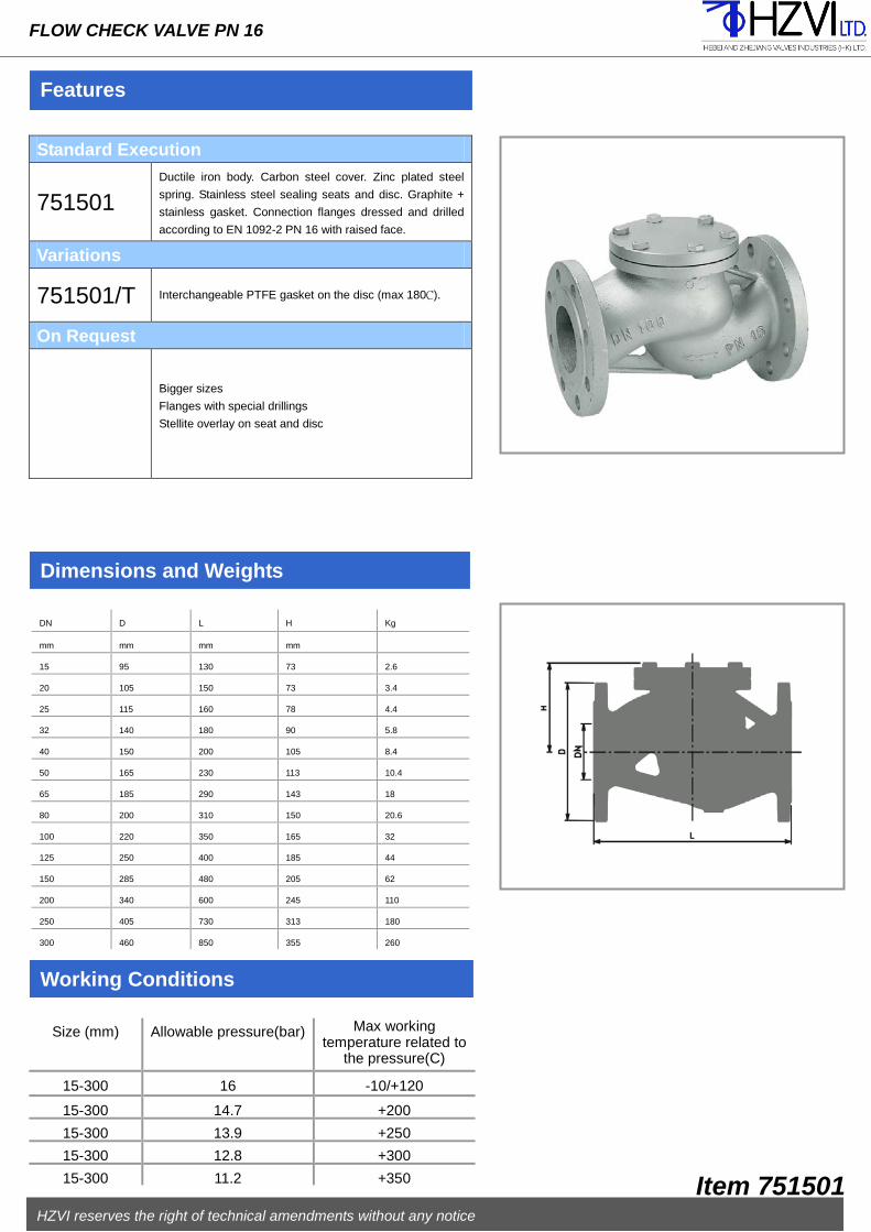
FLOW CHECK VALVE PN 16
Before to assemble the valve at the pipeline check inside the body to
be completely clean, possible extraneous matters have to be
removed in order to ensure a right functioning. If compressed air is at
your disposal, use it for a better cleaning.
The counter-flanges of the pipeline must be parallel and have
aligned holes. Check the space between them, keeping into
account the gaskets and their flattering after bolts closing (it should
not be too much or too litter) and face to face tolerances as per
EN-558-1 standard.
In case of limited pressures, ask for springs with reduced thrust,
indicating the working pressure.
The valve must be assembled following the direction indicated by
the arrow on the body. Fix the valve in the right position at the
pipeline and remember to insert the gaskets between the flanges
centring them as much as possible on the raised face.
The raised faces have to be clean to allow a correct tightness.
Fit the bolts in flanges holes and tighten them maintaining a
diametrically opposed sequence (for a better deformation of the
gaskets).
The sole possible leakage is the non-sealing of the seat normally due to the
wear of time or to possible extraneous matters in the pipeline.
To restore the sealing disassembled the valve: loosen the screws(3), take off the
cover(2), check the seats(5) condition; If it is still integral, carefully clean it as
well as the sliding parts of the disc, of the guide –pin and of the spring(7). If the
spring is damaged, replace it.
If necessary the valve can be completely disassembled using standard tools.
Before to assemble it again, check if the sealing seats are carefully clean and
not damaged; check if each part of the gasket(4) is integral, otherwise it is
recommended to replace them..
Gasket (4) – Spring (7)
HZVI reserves the right of technical amendments without any notice
Item 751501
Functioning
The valve works both horizontally and vertically but if the flow raise the
disc. In case of vertical installations, exclude the assembling with the flow
direction from top to bottom; in case of horizontal installation, keep the
cover upwards.
Features
FLOW CHECK VALVE PN 16
Standard Execution
751501 Ductile iron body. Carbon steel cover. Zinc plated steel
spring. Stainless steel sealing seats and disc. Graphite +
stainless gasket. Connection flanges dressed and drilled
according to EN 1092-2 PN 16 with raised face.
Variations
751501/T Interchangeable PTFE gasket on the disc (max 180C).
On Request
Bigger sizes
Flanges with special drillings
Stellite overlay on seat and disc
Dimensions and Weights
Working Conditions
DN D L H Kg
mm mm mm mm
15 95 130 73 2.6
20 105 150 73 3.4
25 115 160 78 4.4
32 140 180 90 5.8
40 150 200 105 8.4
50 165 230 113 10.4
65 185 290 143 18
80 200 310 150 20.6
100 220 350 165 32
125 250 400 185 44
150 285 480 205 62
200 340 600 245 110
250 405 730 313 180
300 460 850 355 260
Size (mm) Allowable pressure(bar) Max working temperature related to
the pressure(C)
15-300 16 -10/+120
15-300 14.7 +200
15-300 13.9 +250
15-300 12.8 +300
15-300 11.2 +350
HZVI reserves the right of technical amendments without any notice
Item 751501

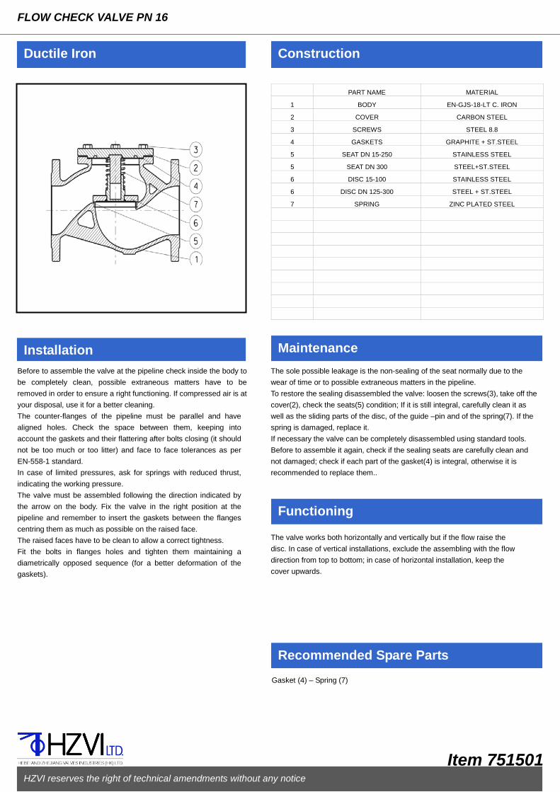
PART NAME MATERIAL
1 BODY EN-GJS-400-18-LT C. IRON
2 COVER CARBON STEEL
3 SCREWS STEEL 8.8
4 GASKETS GRAPHITE + ST.STEEL
5
SEAT STAINLESS STEEL
6 DISC 15-100 STAINLESS STEEL
6 DISC DN 125-250 STEEL + ST.STEEL
7 SPRING ZINC PLATED STEEL
Ductile Iron Construction
Installation Maintenance
Recommended Spare Parts
FLOW VALVE PN 25
Before to assemble the valve at the pipeline check inside the body to
be completely clean, possible extraneous matters have to be
removed in order to ensure a right functioning. If compressed air is at
your disposal, use it for a better cleaning.
The counter-flanges of the pipeline must be parallel and have
aligned holes. Check the space between them, keeping into
account the gaskets and their flattering after bolts closing (it should
not be too much or too litter) and face to face tolerances as per
EN-558-1 standard.
In case of limited pressures, ask for springs with reduced thrust,
indicating the working pressure.
The valve must be assembled following the direction indicated by
the arrow on the body. Fix the valve in the right position at the
pipeline and remember to insert the gaskets between the flanges
centring them as much as possible on the raised face.
The raised faces have to be clean to allow a correct tightness.
Fit the bolts in flanges holes and tighten them maintaining a
diametrically opposed sequence (for a better deformation of the
gaskets).
The sole possible leakage is the non-sealing of the seat normally due to the
wear of time or to possible extraneous matters in the pipeline.
To restore the sealing disassembled the valve: loosen the screws(3), take off the
cover(2), check the seats(5) condition; If it is still integral, carefully clean it as
well as the sliding parts of the disc, of the guide –pin and of the spring(7). If the
spring is damaged, replace it.
If necessary the valve can be completely disassembled using standard tools.
Before to assemble it again, check if the sealing seats are carefully clean and
not damaged; check if each part of the gasket) is integral, otherwise it is
recommended to replace them.
Gasket (4) – Spring (7)
HZVI reserves the right of technical amendments without any notice
Item 751502
Functioning
The valve works both horizontally and vertically but if the flow raise the
disc. In case of vertical installations, exclude the assembling with the flow
direction from top to bottom; in case of horizontal installation, keep the
cover upwards.

Features
FLOW CHECK VALVE PN 25
Standard Execution
751502 Ductile iron body. Carbon steel cover. Zinc plated steel
spring. Stainless steel sealing seats and disc. Graphite +
stainless gasket. Connection flanges dressed and drilled
according to EN 1092-2 PN 25 with raised face.
Variations
751502/T Interchangeable PTFE gasket on the disc (max 180C).
On Request
Bigger sizes
Flanges with special drillings
Stellite overlay on seat and disc
Dimensions and Weights
Working Conditions
DN D L H Kg
mm mm mm mm
15 95 130 73 2.6
20 105 150 73 3.7
25 115 160 78 4.7
32 140 180 90 6.2
40 150 200 105 9
50 165 230 113 11
65 185 190 143 17.4
80 200 310 150 22.8
100 235 350 165 35.8
125 270 400 185 48.8
150 300 480 205 69
200 In preparation
Size (mm) Allowable pressure(bar) Max working temperature related to
the pressure(C)
15-150 25 -10/+120
15-150 23 +200
15-150 21.8 +250
15-150 20 +300
15-150 17.5 +350
HZVI reserves the right of technical amendments without any notice
Item 751502

PART NAME MATERIAL
1 BODY EN-GJS-400-15 DUCTILE IRON
2 BALL ALUMINIUM + NBR RUBBER
3 COVER EN-GJS-400-15 DUCTILE IRON
4 O-RING NBR RUBBER
5 SCREW 8.8 ZINC PLATED STEEL
Ductile Iron Construction
Installation Maintenance
Recommended Spare Parts
BALL CHECK VALVE PN 10 – FLANGED END
Before to assemble the valve at the pipeline check inside the body
to be completely clean, possible impurities have to be removed in
order to ensure a right functioning. If compressed air is at your
disposal, use it for a better cleaning.
The counter-flanges of the pipeline must be parallel and have
aligned holes. Check the space between them, keeping into
account the flattering of the outside part of the joint, that serve as a
gasket, after bolts closing. (It should not be too much or too little)
and face to face tolerances as per EN-558-1 standard.
The valve must be assembled following the direction indicated by
the arrow on the body
Fix the valve in the right position at the pipeline and remember to
insert the gaskets between the flanges centring them as much as
possible on the raised faces.
The raised faces have to be clean to allow a correct tightness.
Fit the bolts in flanges holes and tighten them maintaining a
diametrically opposed sequence (for a better deformation of the
outside part of the joint).
The possible leakage from the valve seat is normally due to the wear of time
of the ball or possible extraneous matters in the pipeline.
To replace the ball (2) loosen the screws (5) take away the cover (3), replace
the gasket (4) if worn out, fit the new ball (2). Clean the valve from possible
impurities in the body and assemble it again.
If necessary the valve can be completely disassembled using standard tools.
Ball (2) – O-ring (4)
HZVI reserves the right of technical amendments without any notice
Item 751801
Functioning
The valve works both horizontally and vertically but if the flow raise the ball.
In case of vertical installations, exclude the assembling with the flow direction
from top to bottom.

Features
BALL CHECK VALVE PN 10 – FLANGED END
Standard Execution
751801
Ductile iron body and cover. Aluminium ball NBR rubber covered. Connection flanges dressed and drilled according to EN 1092-2 PN 10 with raised face. Minimum pressure drop, full bore even for media with sludge or sewage, auto-cleaning system, silent.
On Request
Bigger sizes Flanges with special drillings Cast iron body and cover
Dimensions and Weights
Working Conditions
DN D L H C Kg Kv
mm mm mm mm mm m³/h
40 150 180 97 95 7.5 80
50 165 200 98 95 8.5 90
65 185 240 118 114 12 140
80 200 260 140 128 15 253
80 200 260 140 128 15 253
100 220 300 175 160 22 396
150 285 400 248 230 45 962
200 340 500 310 320 80 1990
250 400 600 400 414 135 3100
300 450 700 455 460 200 4100
Size (mm) Allowable pressure(bar) Max working temperature related to
the pressure(C)
40-300 10 -10/+80
HZVI reserves the right of technical amendments without any notice
Item 881801

PART NAME MATERIAL
1 BODY EN-GJS-400-15 C.IRON
2 BALL BR or RESIN
3 COUPLING EN-GJS-400-15 C.IRON
4 GASKET NBR
5 SCREW ZINC PLATED STEEL 8.8
Ductile Iron Construction
Installation Maintenance
Recommended Spare Parts
BALL CHECK VALVE PN 10 – THREADED END
Before to assemble the valve at the pipeline check inside the body
to be completely clean, possible impurities have to be removed in
order to ensure a right functioning. If compressed air is at your
disposal, use it for a better cleaning.
Screw the valve at the threaded pipe using a suitable wrench.
In order to get a correct sealing on threading it is useful to employ
PTFE or hempen tape or other product compatible with the fluid, in
adequate quantity since an excessive employ could cause the pipe
deformation.
The possible leakage from the valve seat is normally due to the wear of time
of the ball or possible extraneous matters in the pipeline.
To replace the ball (2) loosen the screws (5) take away the cover, replace the
gasket if worn out, fit the new ball (2). Clean the valve from possible impurities
in the body and assemble it again.
If necessary the valve can be completely disassembled using standard tools.
Ball (2) – Gasket (4)
HZVI reserves the right of technical amendments without any notice
Item 751802
Functioning
The valve works both horizontally and vertically but if the flow raise the ball.
In case of vertical installations, exclude the assembling with the flow direction
from top to bottom.

Features
BALL CHECK VALVE PN 10 – THREADED END
Standard Execution
751802 Ductile iron body, NBR or resin ball, BR gasket, zinc plated steel screw, F/F threaded connections according to EN ISO 228/1 standards.
On Request
Not applicable
Dimensions and Weights
Working Conditions
DN L H A C Kg Kv
mm mm mm mm m³/h
32 135 58 50 105 2 24
40 142 70 60 120 2.7 54
50 175 81 70 132 3.5 70
65 195 104 90 157 5 115
80 238 122 105 180 7.6 185
Size (mm) Allowable pressure(bar) Max working temperature related to
the pressure(C)
32-80 10 -10/+80
HZVI reserves the right of technical amendments without any notice
Item 751802

PART NAME MATERIAL
1 BODY EN-GJL-250 CAST IRON
2
SCREEN AISI 304 ST.STEEL
3 GASKET GRAPHITE+ST.STEEL
4
COVER EN-GKL-250 CAST IRON
5 NUT STEEL
6 SCREW STEEL
7 DRAIN PLUG STEEL
8
9
10
11
12
13
14
Cast Iron Construction
Installation Maintenance
Recommended Spare Parts
“Y” STRAINER PN 16
Before to assemble the strainer at the pipeline check inside the body
to be completely clean, possible extraneous matters have to be
removed in order to ensure a right filtering.
The strainer must be assembled following the direction indicated by
the arrow on the body, with flow direction down to up.
The counter-flanges of the pipeline must be parallel and have
aligned holes. Check the space between them, keeping into
account the gaskets and their flattering after bolts closing (it should
not be too much or too litter) and face to face tolerances as per
EN-558-1 standard.
Fix the strainer in the right position at the pipeline and remember to
insert the gaskets between the flanges centering them as much as
possible on the raised faces.
The raised faces have to be clean to allow a correct tightness.
Fit the bolts in flanges holes and tighten them maintaining a
diametrically opposed sequence (for a better deformation of the
gaskets).
The strainer is normally assembled at pipelines in order to avoid the impurities
to damage the equipment installed below, that is on/off valves, regulating
valves, etc.
The screen (2) has to be periodically cleaned.
To carry out this operation: loosen the body/cover screw (6), take off the cover
(4), clean the screen. Before to assemble it again, check if the sealing areas
are carefully cleaned and not damaged; check if each part of the gasket (6) is
integral, otherwise it is recommended to replace it. If necessary the strainer can be completely disassembles using standard
tools.
The threaded plug on the cover, standard provided for strainers from DN 50
up, is useful to discharge the fluid that remains in the strainers.
It is possible to assemble a drain cock instead of the plug, in order to make
easier the draining of the strainer (see pic.1). THIS COCK WILL BE MADE
OF A MATERIAL SUITABLE TO THE FLUID, WORKING PRESSURE AND
TEMPERATURE.
Screen (2) – Gasket (3)
HZVI reserves the right of technical amendments without any notice
Item 781203
ON REQUEST

Features
“Y” STRAINER PN 16
Standard Execution
781203 Cast iron body and cover. Stainless steel screen. Connection flanges dressed and drilled according to EN 1092-2 PN 16 standards with raised face. Drain plug on the cover from DN 65 up.
On Request
Bigger sizes Flanges with special drillings Drain plug on the cover for DN<65 Screen with different kinds of drilling AISI 316 stainless steel screen Cock with tube holder for easy drain
Dimensions and Weights
Working Conditions
DN D L H Kg PN25 Kv
mm mm mm mm m³/h
15 95 130 75 2.4 5.3
20 105 150 75 3 9.5
25 115 160 90 3.8 16.5
32 140 180 90 5.2 20
40 150 200 110 6.8 33
50 165 230 120 9 54
65 185 290 140 11.8 95
80 200 310 165 16.8 140
100 220 350 220 25.2 201
125 250 400 260 37 340
150 285 480 300 58 526
200 340 600 360 112 870
250 405 730 470 162 1260
300 460 850 560 195 1735
Size(mm) Allowable pressure (bar) Max working temperature related to the pressure(C)
15-300 16 -10/+120 15-300 12.8 +200 15-300 11.2 +250 15-300 9.6 +300
HZVI reserves the right of technical amendments without any notice
Item 781203

PART NAME MATERIAL
1 BODY EN-GJL-250 CAST IRON
2 SEAT CAST BRASS
3 STEM DRAWN BRASS
4 WEDGE DN 40-100 CAST BRASS
4 WEDGE DN 125-300 CAST IRON+BRASS
5
BONNET EN-GJL-250 CAST IRON
6 CAP EN-GJL-250 CAST IRON
7 GASKET SBR RUBBER
8 SCREW ZINC PLATED 8.8 C.STEEL
9 WASHER ZINV PLATED C.STEEL
10 HAND-WHEEL CAST IRON
11 O-RING NBR
12 GASKET SBR RUBBER
13 MOTHERSCREW CAST BRASS
14 NUT CARBON STEEL
15 SCREW 8.8 CARBON STEEL
16 SCREW 8.8 CARBON STEEL
Cast Iron Construction
Installation Maintenance
Recommended Spare Parts
FLAT BODY GATE VALVE - INTERNAL SCREW PN10 - MAINTENANCE FREE
Before to assemble the gate valve at the pipeline, open it until about
half-stroke. Check inside the body to be completely clean, possible
extraneous matters have to be removed in order to ensure a right
functioning. If compressed air is at your disposal, use it for a better
cleaning.
The counter-flanges of the pipeline must be parallel and have
aligned holes. Check the space between them, keeping into
account the gaskets and their flattering after bolts closing (it should
not be too much or too litter) and face to face tolerances as per
EN-558-1 standard.
Fix the gate valve in the right position at the pipeline and remember
to insert the gaskets between the flanges centering them as much
as possible on the raised faces.
The raised faces have to be clean to allow a correct tightness.
Fit the bolts in flanges holes and tighten them maintaining a
diametrically opposed sequence (for a better deformation of the
gaskets).Check the right functioning of the gate valve with two or
three complete open-close operations.
THE GATE VALVE NEEDS NO MAINTENANCE.
The sole possible leakage is the one from O-rings (11) due to their accidental
breaking or wear of time, in this case take off the hand-wheel (10) loosening
its stop screw (8), loosen the screws (16), disassemble the cap (6) and
replace the O-rings and the gasket (7) only after checking the integrity of the
gaskets housing in the cap of the stem.
If the gate valve should leak from the seat, do not insist in closing with more
strength by the hand-wheel and do not use levers because it is possible to
damage more the sealing seats; in this case open and close again the valve
in order to remove possible sediments.
If necessary the gate valve can be completely disassembled using standard
tools.
Before to assemble it again, open the valve at two hand-wheel turns, check if
the sealing seats are carefully clean and not damaged; check if each part of
the gasket (12) is integral, otherwise it is recommended to replace it.
Cap (6) complete with O-Ring (11), only if the stem (3) is not worn out, otherwise
replace it with the complete kit (6-11-3-7-12).
HZVI reserves the right of technical amendments without any notice
Item 781302

Features
FLAT BODY GATE VALVE INTERNAL SCREW - PN10 - MAINTENANCE FREE
Standard Execution
781302
Cast iron body, bonnet, cap and hand-wheel. Brass stem and seats. Connection flanges dressed and drilled according to EN 1092-2 PN 10 with raised face. Max working temperature with standard gaskets +80℃
Variations
781302/BIS AISI 304 stainless steel sealing seats, AISI 420 stainless steel stem.
On Request
Bigger sizes Flanges with special drillings Gaskets suitable for temperature over 80℃ Chain-wheel for remote maneuver With gearbox – with electric actuator Micros witches Position indicator Padlock device
Dimensions and Weights
Working Conditions
DN D L H V Kg Kv
mm mm mm mm Mm m³/h
40 150 140 230 125 9 140
50 165 150 245 150 11 250
65 185 170 290 175 15 430
80 200 180 315 175 18 790
100 220 190 355 200 23 1250
125 250 200 415 200 31 1960
150 285 210 460 225 41 2790
200 340 230 545 225 63 2880
250 395 250 635 250 91 4306
300 445 270 725 300 124 6380
Size (mm) Allowable pressure (bar) Max working temperature related to the pressure(C)
With standard gaskets
40-300 10 -10/+80
With special gaskets
40-300 10 +120
40-300 8 +150
HZVI reserves the right of technical amendments without any notice
Item 781302

PART NAME MATERIAL
1 BODY EN-GJL-250 CAST IRON
2 SEAT CAST BRASS
3 STEM DRAWN BRASS
4 WEDGE DN 40-65 CAST BRASS
4 WEDGE DN 80-300 CAST IRON+BRASS
5
BONNET EN-GJL-250 CAST IRON
6 CAP EN-GJL-250 CAST IRON
7 GASKET SBR RUBBER
8 SCREW ZINC PLATED 8.8 C.STEEL
9 WASHER ZINV PLATED C.STEEL
10 HAND-WHEEL CAST IRON
11 O-RING NBR
12 GASKET SBR RUBBER
13 MOTHERSCREW CAST BRASS
14 NUT CARBON STEEL
15 SCREW 8.8 CARBON STEEL
16 SCREW 8.8 CARBON STEEL
Cast Iron Construction
Installation Maintenance
Recommended Spare Parts
OVAL BODY GATE VALVE- INTERNAL SCREW PN16 - MAINTENANCE FREE
Before to assemble the gate valve at the pipeline, open it until
about half-stroke. Check inside the body to be completely clean,
possible extraneous matters have to be removed in order to ensure
a right functioning. If compressed air is at your disposal, use it for a
better cleaning.
The counter-flanges of the pipeline must be parallel and have
aligned holes. Check the space between them, keeping into
account the gaskets and their flattering after bolts closing (it should
not be too much or too litter) and face to face tolerances as per
EN-558-1 standard.
Fix the gate valve in the right position at the pipeline and remember
to insert the gaskets between the flanges centering them as much
as possible on the raised faces.
The raised faces have to be clean to allow a correct tightness.
Fit the bolts in flanges holes and tighten them maintaining a
diametrically opposed sequence (for a better deformation of the
gaskets).Check the right functioning of the gate valve with two or
three complete open-close operations.
THE GATE VALVE NEEDS NO MAINTENANCE.
The sole possible leakage is the one from O-rings (11) due to their accidental
breaking or wear of time, in this case take off the hand-wheel (10) loosening
its stop screw (8), loosen the screws (16), disassemble the cap (6) and
replace the O-rings and the gasket (7) only after checking the integrity of the
gaskets housing in the cap of the stem.
If the gate valve should leak from the seat, do not insist in closing with more
strength by the hand-wheel and do not use levers because it is possible to
damage more the sealing seats; in this case open and close again the valve
in order to remove possible sediments.
If necessary the gate valve can be completely disassembled using standard
tools.
Before to assemble it again, open the valve at two hand-wheel turns, check if
the sealing seats are carefully clean and not damaged; check if each part of
the gasket (12) is integral, otherwise it is recommended to replace it.
Cap (6) complete with or (11), only if the stem (3) is not worn out, otherwise
replace it with the complete kit (6-11-3-7-12).
HZVI reserves the right of technical amendments without any notice
Item 781303

Features
OVAL BODY GATE VALVE – INSIDE SCREW PN 16 - MAINTENANCE FREE
Standard Execution
781303
Cast iron body, bonnet, cap and hand-wheel. Brass stem and seats. Connection flanges dressed and drilled according to EN 1092-2 PN 16 with raised face. Max working temperature with standard gaskets +80℃
Variations
781303/BIS AISI 304 stainless steel sealing seats, AISI 420 stainless steel stem.
On Request
Bigger sizes Flanges with special drillings Gaskets suitable for temperature over 80℃ Chain-wheel for remote maneuver With gearbox – with electric actuator Micro -switches Position indicator Padlock device
Dimensions and Weights
Working Conditions
DN D L H V Kg Kv
mm mm mm mm Mm m³/h
40 150 240 230 125 10 140
50 165 250 265 150 13 250
65 185 270 300 175 18 430
80 200 280 340 175 25 790
100 220 300 370 200 32 1250
125 250 325 415 200 42 1960
150 285 350 460 225 58 2790
200 340 400 555 250 86 2880
250 405 450 665 300 140 4306
300 460 500 730 350 186 6380
Size (mm) Allowable pressure (bar) Max working temperature related to the pressure(C)
With standard gaskets
40-300 16 -10/+80
With special gaskets
40-300 16 +120
40-300 13 +150
HZVI reserves the right of technical amendments without any notice
Item 781303

PART NAME MATERIAL
1 BODY EN-GJL-250 CAST IRON
2 SEAT STAINLESS STEEL
3 STEM STAINLESS STEEL
4 DISC DN 15-100 STAINLESS STEEL
4 DISC DN 125-250 STEEL+ST.STEEL
5
YOKE EN-GJL-250 CAST IRON
6 BELLOWS STAINLESS STEEL
7 GASKETS GRAPHITE+ST.STEEL
8 PACKING CARBO-GRAPHITE
9 GLAND ZINC PLATED STEEL
10 STEM GUIDE-INDEX CARBON STEEL
11 BUSH STEEL
12 ANTIFRICTION BEARINGS TEMPERED STEEL IRON
13 HANDWHEEL STEEL
14 STOP HANDWHEEL NUT CARBON STEEL
15 BLANK NUT CARBON STEEL
16 ANTI-FRICTION DISK STAINLESS STEEL
17 ELASTIC PIN CARBON STEEL
18 SCREWS CARBON STEEL
19 ELASTIC RING STAINLESS STEEL
20 LUBRICATOR ZINC PLATED STEEL
21 STOP SCREW ZINC PLATED STEEL
22 RISE LIMITER SCREW ZINC PLATED STEEL
Cast Iron Construction
Installation Maintenance
Recommended Spare Parts
STREAMLINED FLOW VALVE WITH BELLOWS – EXTERNAL SCREW PN 16 - MAINTENANCE FREE
Before to assemble the valve at the pipeline, open it until about
half-stroke. Check inside the body to be completely clean, possible
extraneous matters have to be removed in order to ensure a right
functioning. If compressed air is at your disposal, use it for a better
cleaning.
The counter-flanges of the pipeline must be parallel and have
aligned holes. Check the space between them, keeping into
account the gaskets and their flattering after bolts closing (it should
not be too much or too litter) and face to face tolerances as per
EN-558-1 standard.
The valve must be assembled following the direction indicated by
the arrow on the body. Fix the valve in the right position at the
pipeline and remember to insert the gaskets between the flanges
centering them as much as possible on the raised face.
The raised faces have to be clean to allow a correct tightness.
Fit the bolts in flanges holes and tighten them maintaining a
diametrically opposed sequence (for a better deformation of the
gaskets).Check the right functioning of the gate valve with two or
three complete open-close operations.
THIS KIND OF VALVE NEEDS NO MAINTENANCE SINCE THE BELLOWS
HAS BEEN TESTED FOR THOUSANDS MANOEUVRES.
The leakage of fluid from the stuffing box indicates the accidental breaking of the
bellows (6). Waiting to repair or replace the valve, tighten the gland (9).
In order to add more packing when plants not in pressure neither temperature,
unscrew the gland (9), fit new packing and tighten it again.
Using the backseat it is possible to add more packing when the plant is working,
unfasten completely the locking set screw (21) and the rise limiter(22) (if
proved), use the backseat on the stem forcing the opening maneuver, check its
functionality and act following the above mentioned operations. This must be
carried out within a short term from the bellows breaking since the fluid could
damage the functionality of the backseat.
If necessary the valve can be completely disassembled using standard tools.
It is economically advisable to repair the valve only for big sizes.
Before to assemble it again, open the valve at two hand-wheel turns, check if the
sealing seats are carefully clean and not damaged; check if each part of the
gaskets(7-8) is integral, otherwise it is recommended to replace them.
Functioning instructions are supplied together with each valve.
Packing (8) – Gaskets (7) – Complete kit: stem/bellows/disc (3-6-4)
HZVI reserves the right of technical amendments without any notice
Item 781401

Features
STREAMLINED FLOW VALVE WITH BELLOWS – EXTERNAL SCREW PN 16 - MAINTENANCE FREE
Standard Execution
781401
Stainless steel body and yoke, stem, bellows and sealing
seats. Graphite + stainless steel gaskets. Carbon steel
hand-wheel. The valve is standard provided by: position
indicator, safety backseat on the stem, rise limiter,
lubricator, locking set screw. Connection flanges dressed
and drilled according to EN 1092-1 PN 40 with raised
face.
Variations
781401/R Parabolic disc 781401/E
Balanced disc
781401/T Interchangeable PTFE gasket on the disc(max 180℃)
781401/A SDNR disc(check + on/off function)
781401/RT Parabolic disc with interchangeable PTFE gasket(max
180C)
On Request
Bigger sizes
Flanges with special drillings
Chain-wheel for remote maneuver
Pneumatic actuator S.A. or D.A. – electric actuator with
fittings
Padlock device
Satellite overlay on seat and disc
Dimensions and Weights
Working Conditions
DN D L H V Kg Kv
mm mm mm mm Mm m³/h
15 95 130 234 125 3.8 4.6
20 105 150 243 125 4.4 7.3
25 115 160 253 125 5.3 11.7
32 140 180 242 125 6.8 16.8
40 150 200 275 150 9 26.7
50 165 230 276 150 11.3 42.6
65 185 290 377 200 21 77.9
80 200 310 378 200 24 111
100 220 350 401 250 31 177
125 250 400 442 300 45.5 262
150 285 480 494 350 65 368
200 340 600 620 400 117.5 664
*See item 64 for bigger sizes
Size (mm) Allowable pressure (bar) Max working temperature related to the pressure(C)
15-200 16 -10/+120
15-200 12.8 +200
15-200 11.2 +250
15-200 11.2 +300
HZVI reserves the right of technical amendments without any notice
Item 781401

PART NAME MATERIAL
1 BODY EN-GJL-250 CAST IRON
2 SEAT STAINLESS STEEL
3 STEM STAINLESS STEEL
4 DISC DN 15-100 STAINLESS STEEL
4 DISC DN 125-200 STEEL+ST.STEEL
5
BONNET EN-GJL-250 CAST IRON
6 BELLOWS STAINLESS STEEL
7 GASKETS GRAPHITE+ST.STEEL
8 PACKING CARBO-GRAPHITE
9 GLAND ZINC PLATED STEEL
10 BOTTOM RING ZINC PLATED STEEL
11 ANTIFRICTION BEARINGS STAINLESS STEEL
12 ELASTIC RING STAINLESS STEEL
13 HAND-WHEEL STEEL
14 NUT ZINC PLATED STEEL
15 INDENTIFICATION PLATE ALUMINIUM
16 WASHER STEEL
17 SCREWS STEEL
18 SCREWS STEEL 8.8
Cast Iron Construction
Installation Maintenance
Recommended Spare Parts
STREAMLINED FLOW VALVE WITH BELLOWS - INTERNAL SCREW PN 16 - MAINTENANCE FREE
Before to assemble the valve at the pipeline, open it until about
half-stroke. Check inside the body to be completely clean, possible
extraneous matters have to be removed in order to ensure a right
functioning. If compressed air is at your disposal, use it for a better
cleaning.
The counter-flanges of the pipeline must be parallel and have
aligned holes. Check the space between them, keeping into
account the gaskets and their flattering after bolts closing (it should
not be too much or too litter) and face to face tolerances as per
EN-558-1 standard.
The valve must be assembled following the direction indicated by
the arrow on the body. Fix the valve in the right position at the
pipeline and remember to insert the gaskets between the flanges
centering them as much as possible on the raised face.
The raised faces have to be clean to allow a correct tightness.
Fit the bolts in flanges holes and tighten them maintaining a
diametrically opposed sequence (for a better deformation of the
gaskets).Check the right functioning of the gate valve with two or
three complete open-close operations.
THIS KIND OF VALVE NEEDS NO MAINTENANCE SINCE THE BELLOWS
HAS BEEN TESTED FOR THOUSANDS MANOEUVRES.
The sole possible leakage is the on due to the accidental breaking of the bellows
(6), noticeable by the fluid loss from the stuffing box. This anomaly is due to the
wear (of time) or to water-hammer or to extraneous matters in the pipeline.
Waiting to repair to replace the valve, tighten the gland (9) in order to reduce the
leakage.
It is possible to repair the valve (economically advisable only for the big sizes) as
long as bonnet threading (5) is not too much worn; unscrew the screws (17) and
disassemble the bonnet from the body, take off stem/bellow/disc (3-6-4) and
replace them with a new kit.
If the valve should leak from the seat, do not insist in closing with more strength
by the hand wheel and do not use levers because it is possible to damage more
the sealing seats; in this case open and close again the valve in order to remove
possible sediments.
If necessary the valve can be completely disassembled using standard tools.
Before to assemble it again, open the valve at two hand wheel turns, check if the
sealing seats are carefully clean and not damaged; check if each part of the
gaskets(7-8) is integral, otherwise it is recommended to replace them.
Packing (8) – Gaskets (7) – Complete kit: stem/bellows/disc (3-6-4)
HZVI reserves the right of technical amendments without any notice
Item 781402

Features
STREAMLINED FLOW VALVE WITH BELLOWS - INTERNAL SCREW PN 16 - MAINTENANCE FREE
Standard Execution
781402 Cast iron body and bonnet. Stainless steel stem, bellows
and sealing seats. Graphite + stainless steel gaskets.
Carbon steel hand wheel. Connection flanges dressed and
drilled according to EN 1092-2 PN 16 with raised face.
VARIATIONS
781402/R Parabolic disc
781402/T Interchangeable PTFE gasket on the disc(max 180℃)
ON REQUEST
Bigger sizes
Flanges with special drillings
Chain-wheel for remote maneuver
Pneumatic actuator S.A. or D.A. – electric actuator with
fittings
Padlock device
Stellite overlay on seat and disc
Dimensions and Weights
Working Conditions
DN D L H H' V Kg Kv
mm mm mm mm Mm Mm m³/h
15 95 130 167 175 100 2.2 4.6
20 105 150 167 175 100 3 7.3
25 115 160 183 191 100 4 11.7
32 140 180 183 193 125 5.5 16.8
40 150 200 216 229 150 8.2 26.7
50 165 230 216 231 150 10.2 42.6
65 185 290 290 314 200 18 77.9
80 200 310 293 316 200 20.5 111
100 220 350 321 353 225 30.6 177
150 285 480 398 443 350 64 368
200 340 600 455 517 400 110 664
*See item 54 for bigger sizes
Size (mm) Allowable pressure (bar) Max working temperature related to the pressure(C)
15-200 16 -10/+120
15-200 12.8 +200
15-200 11.2 +250
15-200 9.6 +300
HZVI reserves the right of technical amendments without any notice
Item 781402

PART NAME MATERIAL
1 BODY EN-GJL-250 CAST IRON
2 COVER CARBON STEEL
3 SCREWS STEEL 8.8
4 GASKETS GRAPHITE + ST.STEEL
5
SEAT STAINLESS STEEL
6 DISC DN 15-100 STAINLESS STEEL
6 DISC 125-200 STEEL + ST.STEEL
7 SPRING ZINC PLATED STEEL
Steel Construction
Installation Maintenance
Recommended Spare Parts
STREAMLINED FLOW CHECK VALVE PN 16
Before to assemble the valve at the pipeline check inside the body to
be completely clean, possible extraneous matters have to be
removed in order to ensure a right functioning. If compressed air is at
your disposal, use it for a better cleaning.
The counter-flanges of the pipeline must be parallel and have
aligned holes. Check the space between them, keeping into
account the gaskets and their flattering after bolts closing (it should
not be too much or too litter) and face to face tolerances as per
EN-558-1 standard.
In case of limited pressures, ask for springs with reduced thrust,
indicating the working pressure.
The valve must be assembled following the direction indicated by
the arrow on the body. Fix the valve in the right position at the
pipeline and remember to insert the gaskets between the flanges
centring them as much as possible on the raised face.
The raised faces have to be clean to allow a correct tightness.
Fit the bolts in flanges holes and tighten them maintaining a
diametrically opposed sequence (for a better deformation of the
gaskets). Check the right functioning of the valve with two or three
complete open-close operations.
The sole possible leakage is the non-sealing of the seat normally due to the
wear of time or to possible extraneous matters in the pipeline.
To restore the sealing disassembled the valve: loosen the screws(3), take off the
cover(2), check the seats(5) condition; If it is still integral, carefully clean it as
well as the sliding parts of the disc, of the guide –pin and of the spring(7). If the
spring is damaged, replace it. If necessary the valve can be completely
disassembled using standard tools.
Before to assemble it again, check if the sealing seats are carefully clean and
not damaged; check if each part of the gasket(4) is integral, otherwise it is
recommended to replace it.
Gasket (4) – Spring (7)
HZVI reserves the right of technical amendments without any notice
Item 781501
Functioning
The valve works both horizontally and vertically but if the flow raise the
disc. In case of vertical installations, exclude the assembling with the flow
direction from top to bottom; in case of horizontal installation, keep the
cover upwards.

Features
STREAMLINED FLOW CHECK VALVE PN 16
Standard Execution
781501 Cast iron body. Carbon steel cover. Zinc plated steel
spring. Stainless steel sealing seats and disc. Graphite +
stainless gasket. Connection flanges dressed and drilled
according to EN 1092-2 PN 16 with raised face.
Variations
781501/T Interchangeable PTFE gasket on the disc (max 180C).
On Request
Bigger sizes
Flanges with special drillings
Stellite overlay on seat and disc
Dimensions and Weights
Working Conditions
DN D L H Kg
mm mm mm mm
15 95 130 73 2.6
20 105 150 73 3.4
25 115 160 78 4.4
32 140 180 90 5.8
40 150 200 105 8.4
50 165 230 113 10.4
65 185 290 143 18
80 200 310 150 20.6
100 220 350 165 32
125 250 400 185 44
150 285 480 205 62
200 340 600 245 110
*See item 751501 for bigger sizes
Size(mm) Allowable pressure(bar) Max working temperature related to
the pressure(C)
15-200 16 -10/+120
15-200 12.8 +200
15-200 11.2 +250
15-200 9.6 +300
HZVI reserves the right of technical amendments without nay notice
Item 781501
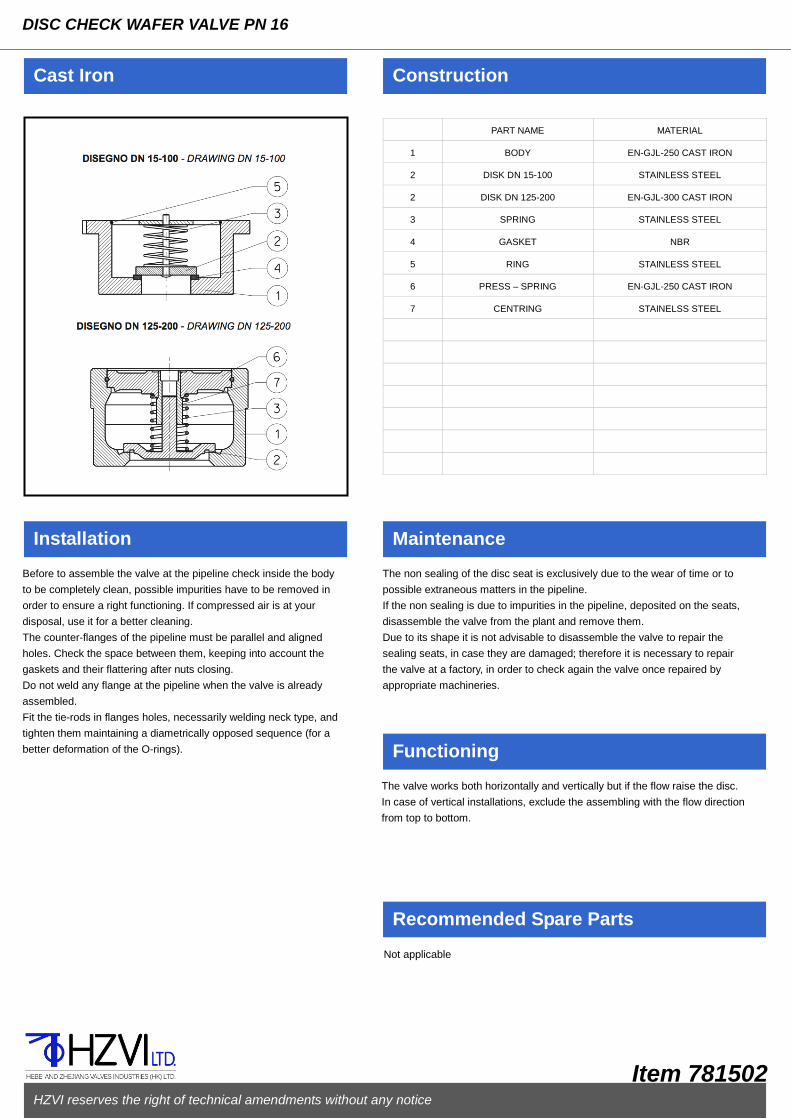
PART NAME MATERIAL
1 BODY EN-GJL-250 CAST IRON
2 DISK DN 15-100 STAINLESS STEEL
2 DISK DN 125-200 EN-GJL-300 CAST IRON
3 SPRING STAINLESS STEEL
4
GASKET NBR
5 RING STAINLESS STEEL
6 PRESS – SPRING EN-GJL-250 CAST IRON
7 CENTRING STAINELSS STEEL
Cast Iron Construction
Installation Maintenance
Recommended Spare Parts
DISC CHECK WAFER VALVE PN 16
Before to assemble the valve at the pipeline check inside the body
to be completely clean, possible impurities have to be removed in
order to ensure a right functioning. If compressed air is at your
disposal, use it for a better cleaning.
The counter-flanges of the pipeline must be parallel and aligned
holes. Check the space between them, keeping into account the
gaskets and their flattering after nuts closing.
Do not weld any flange at the pipeline when the valve is already
assembled.
Fit the tie-rods in flanges holes, necessarily welding neck type, and
tighten them maintaining a diametrically opposed sequence (for a
better deformation of the O-rings).
The non sealing of the disc seat is exclusively due to the wear of time or to
possible extraneous matters in the pipeline.
If the non sealing is due to impurities in the pipeline, deposited on the seats,
disassemble the valve from the plant and remove them.
Due to its shape it is not advisable to disassemble the valve to repair the
sealing seats, in case they are damaged; therefore it is necessary to repair
the valve at a factory, in order to check again the valve once repaired by
appropriate machineries.
Not applicable
HZVI reserves the right of technical amendments without any notice
Item 781502
Functioning
The valve works both horizontally and vertically but if the flow raise the disc.
In case of vertical installations, exclude the assembling with the flow direction
from top to bottom.

Features
DISC CHECK WAFER VALVE PN 16
Standard Execution
781502/GH Cast iron body. Stainless steel disk from DN 15 to DN 100, ring and spring. Cast iron disk from DN 125 to ND 200. Suitable to be assembled between flanges PN 10/16 and ANSI 150.
Variations
781502/I AISI 316 stainless steel body
On Request
From DN 125 to DN 200:EPDM, BUNA, VITON, PTFE sealing seat
Dimensions and Weights
Working Conditions
DN D L P Kg Kv
mm mm mm mm m³/h
15 50 16 15 0.1 4
20 60 19 20 0.17 8
25 70 22 25 0.25 12
32 81 28 32 0.42 20
40 91 31.5 40 0.63 27
50 106 40 50 0.9 40
65 126 46 65 1.6 70
80 141 50 77 2.1 110
100 170 60 100 4.5 180
125 183 90 125 6.5 190
150 210 106 150 8.3 270
200 264 142 200 14.5 506
Size (mm) Allowable pressure (bar) Max working temperature related to the pressure(C)
15-100 16 -10/+100 125-200 16 +120
HZVI reserves the right of technical amendments without any notice
Item 781502

PART NAME MATERIAL
1 BODY EN-GJL-250 CAST IRON
2 SWING EN-GJS-400-15 C.IRON
3 GASKET EPDM
4 PIN STAINLESS STEEL
5
SPRING STAINLESS STEEL
6 RING FROM DN 200 ZINC PLATED STEEL
Cast Iron Construction
Installation Maintenance
Recommended Spare Parts
DOUBLE SWING CHECK WAFER VALVE
Before to assemble the valve at the pipeline check inside the body
to be completely clean, possible impurities have to be removed in
order to ensure a right functioning. If compressed air is at your
disposal, use it for a better cleaning.
The counter-flanges of the pipeline must be parallel and aligned
holes. Check the space between them, keeping into account the
gaskets and their flattering after nuts closing.
Do not weld any flange at the pipeline when the valve is already
assembled.
Fit the tie-rods in flanges holes, necessarily welding neck type, and
tighten them maintaining a diametrically opposed sequence (for a
better deformation of the O-rings).
The non sealing of the disc seat is exclusively due to the wear of time of the
sealing ring.
if the non sealing is due to impurities in the pipeline, deposited on the seats,
disassemble the valve from the plant and remove them.
Due to its shape it is not advisable to disassemble the valve to repair the
sealing seats, in case they are damaged; therefore it is necessary to repair
the valve at a factory, in order to check again the valve once repaired by
appropriate machineries.
Not applicable
HZVI reserves the right of technical amendments without any notice
Item 781503
Functioning
The valve works both horizontally and vertically but if the flow raise the disc.
In case of vertical installations, exclude the assembling with the flow direction
from top to bottom.

Features
DOUBLE SWING CHECK WAFER VALVE
Standard Execution
781503 Cast iron body. Bronze swing. Stainless steel pin and spring. NBR gasket. Suitable to be assembled between flanges PN 16 ad ANSI 150.
On Request
Bigger sizes with only PN 10 Stainless steel Stainless steel swing
Dimensions and Weights
Working Conditions
DN D L P Kg Kv
mm mm mm mm m³/h
50 109 54 60 1.9 78
65 129 54 73 2.7 78
80 144 57 90 3.5 130
100 164 64 115 4.7 258
125 194 70 142 7.2 690
150 220 76 169 9.5 690
200 275 95 219 16.5 1466
250 330 108 273 28 2586
300 380 144 324 42.5 3540
Size (mm) Allowable pressure (bar) Max working temperature related to the pressure(C)
40-300 16 -10/+100
HZVI reserves the right of technical amendments without any notice
Item 781503
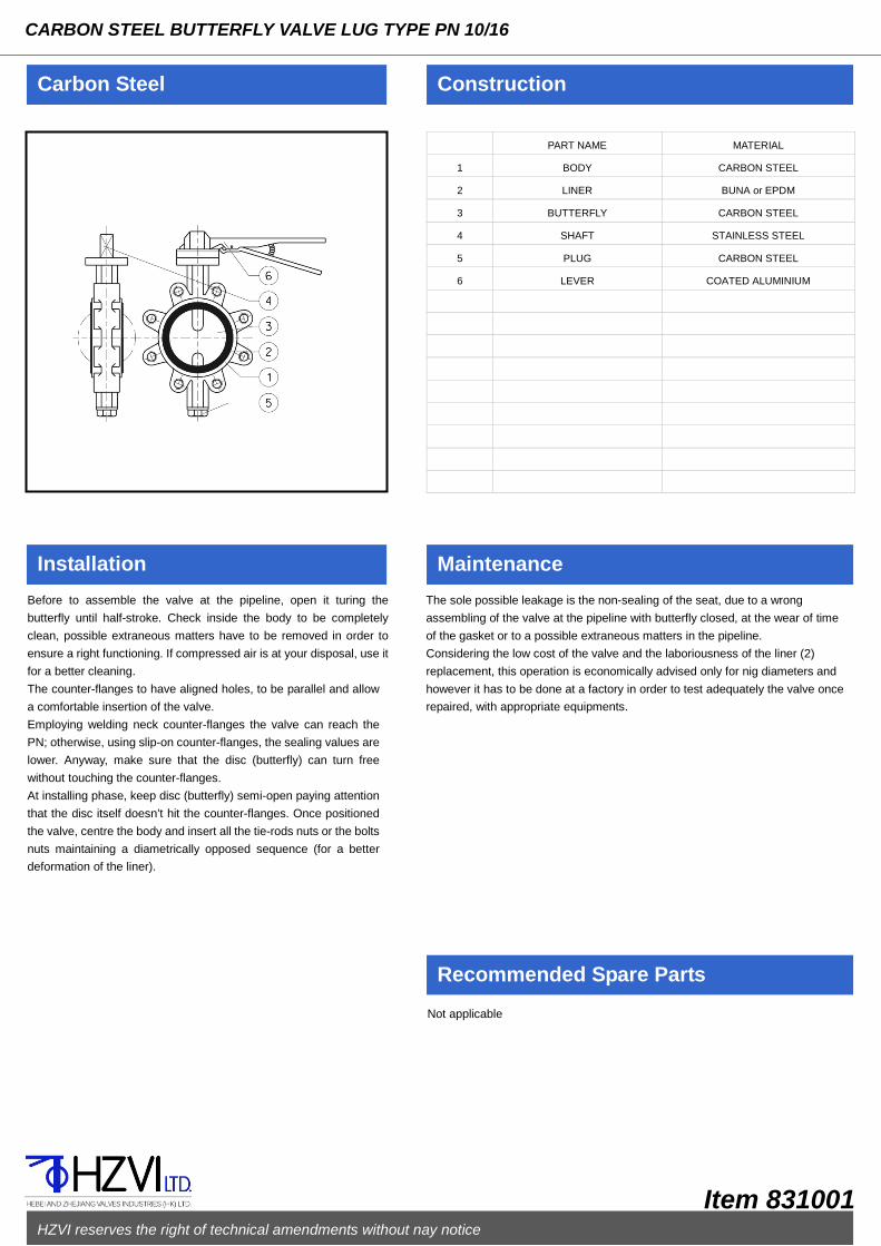
PART NAME MATERIAL
1 BODY CARBON STEEL
2 LINER BUNA or EPDM
3 BUTTERFLY CARBON STEEL
4 SHAFT STAINLESS STEEL
5 PLUG CARBON STEEL
6
LEVER COATED ALUMINIUM
Carbon Steel Construction
Installation Maintenance
Recommended Spare Parts
CARBON STEEL BUTTERFLY VALVE LUG TYPE PN 10/16
Before to assemble the valve at the pipeline, open it turing the
butterfly until half-stroke. Check inside the body to be completely
clean, possible extraneous matters have to be removed in order to
ensure a right functioning. If compressed air is at your disposal, use it
for a better cleaning.
The counter-flanges to have aligned holes, to be parallel and allow
a comfortable insertion of the valve.
Employing welding neck counter-flanges the valve can reach the
PN; otherwise, using slip-on counter-flanges, the sealing values are
lower. Anyway, make sure that the disc (butterfly) can turn free
without touching the counter-flanges.
At installing phase, keep disc (butterfly) semi-open paying attention
that the disc itself doesn’t hit the counter-flanges. Once positioned
the valve, centre the body and insert all the tie-rods nuts or the bolts
nuts maintaining a diametrically opposed sequence (for a better
deformation of the liner).
The sole possible leakage is the non-sealing of the seat, due to a wrong
assembling of the valve at the pipeline with butterfly closed, at the wear of time
of the gasket or to a possible extraneous matters in the pipeline.
Considering the low cost of the valve and the laboriousness of the liner (2)
replacement, this operation is economically advised only for nig diameters and
however it has to be done at a factory in order to test adequately the valve once
repaired, with appropriate equipments.
Not applicable
HZVI reserves the right of technical amendments without nay notice
Item 831001

Features
CARBON STEEL BUTTERFLY VALVE LUG TYPE PN 10/16
Standard Execution
831001
Carbon steel body and butterfly. Stainless steel stem.
Coated aluminium lever. Buna or EPDM liner. Suitable to
be assembled between EN 1092-1 PN 10-10 and ANSI
150 flanges. This kind of butterfly valve can be
assembled at the end of pipes as end-line valve at a 50%
reduced max working pressure
Variations
831001/FI AISI 316 stainless steel butterfly
831001/TI AISI 316 stainless steel body and butterfly
On Request
PTFE or EPDM HT liner
Gearbox with hand-wheel
Extension
Pneumatic actuator S.A. or D.A.
Dimensions and Weights
Working Conditions
DN/ND L H A B V F G Kg Kv*
mm mm mm mm mm mm mm mm m³/h
40 33 229 90 98 313 6.6 31 111 3.4
68.9 50 43 246 96 109 313 7.2 36 120
4.3 112 65 46 271 108 122 313 12.9 53
138 5.7 172 170 205 16.8 65 5 522
100 52 295 187 205 14.2 86 7 816
125 56 324 205 250 33.8 112 10 1275
150 56 349 217 250 46.5 140 11 1835
200 60 442 257 400 69 191 16 3263
250 68 452 255 - 91 241 30 5099
300 78 522 288 - 111 290 39 7342
350 78 600 320 - 131 330 51 9994
400 102 658 339 - 144 376 73 13053
*Opening angle 90
Size (mm) Allowable pressure(bar) Max working temperature related to the pressure(C)
40-200 16 -10/+95
250-400 10 -10/+95
- Allowed picks until 110C
HZVI reserves the right of technical amendments without nay notice
Item 831001
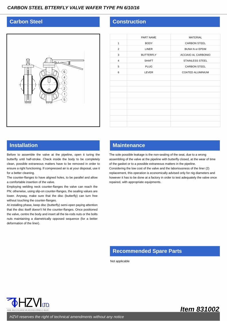
PART NAME MATERIAL
1 BODY CARBON STEEL
2 LINER BUNA N or EPDM
3 BUTTERFLY ACCIAIO AL CARBONIO
4 SHAFT STAINLESS STEEL
5 PLUG CARBON STEEL
6
LEVER COATED ALUMINIUM
Carbon Steel Construction
Installation Maintenance
Recommended Spare Parts
CARBON STEEL BTTERFLY VALVE WAFER TYPE PN 6/10/16
Before to assemble the valve at the pipeline, open it turing the
butterfly until half-stroke. Check inside the body to be completely
clean, possible extraneous matters have to be removed in order to
ensure a right functioning. If compressed air is at your disposal, use it
for a better cleaning.
The counter-flanges to have aligned holes, to be parallel and allow
a comfortable insertion of the valve.
Employing welding neck counter-flanges the valve can reach the
PN; otherwise, using slip-on counter-flanges, the sealing values are
lower. Anyway, make sure that the disc (butterfly) can turn free
without touching the counter-flanges.
At installing phase, keep disc (butterfly) semi-open paying attention
that the disc itself doesn’t hit the counter-flanges. Once positioned
the valve, centre the body and insert all the tie-rods nuts or the bolts
nuts maintaining a diametrically opposed sequence (for a better
deformation of the liner).
The sole possible leakage is the non-sealing of the seat, due to a wrong
assembling of the valve at the pipeline with butterfly closed, at the wear of time
of the gasket or to a possible extraneous matters in the pipeline.
Considering the low cost of the valve and the laboriousness of the liner (2)
replacement, this operation is economically advised only for nig diameters and
however it has to be done at a factory in order to test adequately the valve once
repaired, with appropriate equipments.
Not applicable
HZVI reserves the right of technical amendments without any notice
Item 831002

Features
CARBON STEEL BTTERFLY VALVE WAFER TYPE PN 6/10/16
Standard Execution
831002
Carbon steel body and butterfly. Stainless steel stem. Coated
aluminium lever. Buna or EPDM liner. Suitable to be
assembled between EN 1092-1 PN 10-16 and ANSI 150
flanges. The butterfly valve can be assembled at the end of a
pipe as end-line valve keeping into consideration the
suggestions at page 150.
Variations
831002/FI AISI 316 stainless steel butterfly
831002/TI AISI 316 stainless steel body and butterfly
On Request
PTFE or EPDM HT liner
Gearbox with hand-wheel
Extension
Pneumatic actuator S.A. or D.A.
Dimensions and Weights
Working Conditions
DN L H A B V F G Kg Kv*
mm mm mm mm mm mm mm mm m³/h
40 33 229 90 98 313 6.6 31 3 68
50 43 246 96 109 313 7.2 36 3.7 112
65 46 271 108 122 313 12.9 53 4.7 172
80 46 291 118 132 313 19.3 69 5 259
100 52 326 132 153 313 27.15 90 5.8 474
125 56 368 150 177 313 36.4 115 8.2 970
150 56 40 165 194 313 48.6 142 9.3 1681
200 60 460 194 225 313 69.8 199 12.6 2800
250 68 536 220 275 407 90 238 19.5 4310
300 78 600 262 297 407 111.1 289 30.8 6465
*Opening angle 90
Size (mm) Allowable pressure(bar) Max working temperature related to
the pressure(C)
With Buna liner
40-300 10/16 -10/+100
With EPDM liner
40-300 10/16 -10/+120
HZVI reserves the right of technical amendments without any notice
Item 831002

PART NAME MATERIAL
1 BODY GP 240 GH+N STEEL
2
COVER GP 240 GH+N STEEL
3 SCREEN AISI 304 ST.STEEL
4
STUD CARBON STEEL
5 NUT CARBON STEEL
6 GASKET ASBESTOS FREE
7
8
9
10
11
12
13
14
Steel Construction
Installation Maintenance
Recommended Spare Parts
“Y” STRAINER PN 40
Before to assemble the strainer at the pipeline check inside the body
to be completely clean, possible extraneous matters have to be
removed in order to ensure a right filtering.
The strainer must be assembled following the direction indicated by
the arrow on the body, with flow direction down to up.
The counter-flanges of the pipeline must be parallel and have
aligned holes. Check the space between them, keeping into
account the gaskets and their flattering after bolts closing (it should
not be too much or too litter) and face to face tolerances as per
EN-558-1 standard.
Fix the strainer in the right position at the pipeline and remember to
insert the gaskets between the flanges centering them as much as
possible on the raised faces.
The raised faces have to be clean to allow a correct tightness.
Fit the bolts in flanges holes and tighten them maintaining a
diametrically opposed sequence (for a better deformation of the
gaskets).
The strainer is normally assembled at pipelines in order to avoid the impurities
to damage the equipment installed below, which is on/off valves, regulating
valves, etc.
The screen (3) has to be periodically cleaned. To carry out this operation:
loosen the body/cover nuts (3), take off the cover (2), clean the screen.
If necessary the strainer can be completely disassembles using standard
tools.
Before to assemble it again, check if the sealing areas are carefully cleaned
and not damaged; check if each part of the gasket (6) is integral, otherwise it
is recommended to replace it.
Screen (3) – Gasket (6)
HZVI reserves the right of technical amendments without any notice
Item 831201

Features
“Y” STRAINER PN 40
Standard Execution
831201 Carbon steel body and bonnet. Stainless steel screen. Asbestos free gasket. Connection flanges dressed and drilled according to EN 1092 PN 40 with raised face.
Variations
831201/TI AISI 316 stainless steel.
On Request
Bigger sizes Flanges with special drillings Drain plug on the cover Screen with different kinds of drilling AISI 316 stainless steel screen BW or SW connections Cock with tube holder for easy drain
Dimensions and Weights
Working Conditions
DN D L H Kg Kv
mm mm mm mm m³/h
15 95 130 70 3 6
20 105 150 75 4 10
25 115 160 80 4.5 15
32 140 180 90 6 24
40 150 200 100 8 38
50 165 230 115 10 48
65 185 290 130 19 87
80 200 310 145 23 130
100 235
350 170 34 173
125 270 400 220 45 315
150 300 480 290 65 440
200 375 600 370 110 825
250 450 730 420 118 1234
300 515 850 530 240 1740
Size (mm) Allowable pressure (bar) Max working temperature related to the pressure(C)
15-300 40 -10/+50 15-300 37.3 +100
15-300 30.2 +200
15-300 25.8 +300 15-300 23.1 +400
HZVI reserves the right of technical amendments without any notice
Item 831201

PART NAME MATERIAL
1 BODY GP 240 GH+N STEEL
2 BONNET GP 240 GH+N STEEL
3 WEDGE GP 240 GH+N STEEL
4 LUBRICATOR ZINC PLATED STEEL
5
STEM STAINLESS STEEL
6 BODY SEAT STAINLESS STEEL
7 WEDGE SEAT STAINLESS STEEL
8 GASKET GRAPHITE+ST.STEEL
9 PACKING GRAPHITE+ST.STEEL
10 GLAND CARBON STEEL
11 TIE ROD STEEL
12 NUT STEEL
13 MOTHERSCREW STEEL
14 HAND-WHEEL PRESSED STEEL
15 BUSH STEEL
16 ELASTIC RING STEEL
Steel Construction
Installation Maintenance
Recommended Spare Parts
FLAT BODY GATE VALVE-EXTERNAL SCREW PN16
Before to assemble the gate valve at the pipeline, open it until
about half-stroke. Check inside the body to be completely clean,
possible extraneous matters have to be removed in order to ensure
a right functioning. If compressed air is at your disposal, use it for a
better cleaning.
The counter-flanges of the pipeline must be parallel and have
aligned holes. Check the space between them, keeping into
account the gaskets and their flattering after bolts closing (it should
not be too much or too litter) and face to face tolerances as per
EN-558-1 standard.
Fix the gate valve in the right position at the pipeline and remember
to insert the gaskets between the flanges centering them as much
as possible on the raised faces.
The raised faces have to be clean to allow a correct tightness.
Fit the bolts in flanges holes and tighten them maintaining a
diametrically opposed sequence (for a better deformation of the
gaskets).Check the right functioning of the gate valve with two or
three complete open-close operations.
Occasionally verify the sealing of the packing (9), in case of leakages tighten
the gland nuts (12).
To add more packing, when plant is not in pressure and temperature, loosen
the nuts (12), rise up the gland (10), fit new packing and tighten again gland
(10). If the gate valve is working, use the backseat obtained on the stem
forcing the opening maneuver; check if the backseat works (it is possible to
find the backseat worn out if the gate valve is installed since time) and act
following the above mentioned operations.
If the gate valve should leak from the seat, do not insist in closing with more
strength by the hand -wheel (14) because it is possible to damage more the
sealing seats; open and close again the gate valve in order to remove
possible sediments.
If necessary the gate valve can be completely disassembled using standard
tools.
Before to assemble it again, open the valve at two hand wheel turns, check if
the sealing seats are carefully clean and not damaged; check if each part of
the gasket is integral, otherwise it is recommended to replace it.
Insert grease by the lubricator (4).
Packing (9) – Gasket (8)
HZVI reserves the right of technical amendments without any notice
Item 881301

Features
FLAT BODY GATE VALVE - EXTERNAL SCREW PN 16
Standard Execution
881301
Carbon steel body, bonnet, wedge. Pressed steel hand-wheel. Stainless steel stem and sealing seats. Graphite + stainless steel gaskets. Connection flanges dressed and drilled according to EN 1092-1 PN 16 with raised face.
On Request
Bigger sizes Flanges with special drillings Stainless steel Chain-wheel for remote maneuver
Dimensions and Weights
Working Conditions
DN D L H H' V Kg Kv
mm mm mm mm Mm mm m³/h
50 165 150 315 375 200 15 238
65 185 170 370 450 200 25 405
80 200 180 410 500 200 27 615
100 220 290 450 560 200 35 965
125 250 200 525 660 250 40 1554
150 285 210 600 765 250 55 2250
200 340 230 760 975 300 82 4020
250 405 250 990 1255 400 155 6631
350 520 290 1245 1610 400 265 13456
400 580 310 1350 1770 500 320 17650
Size (mm) Allowable pressure(bar) Max working temperature related to
the pressure(C)
50-400 16 -10/+50 50-400 14.9 +100 50-400 12.4 +200 50-400 10.3 +300 50-400 9.2 +400
HZVI reserves the right of technical amendments without any notice
Item 881301

PART NAME MATERIAL
1 BODY GP 240 GH+N STEEL
2 BONNET GP 240 GH+N STEEL
3 RING GP 240 GH+N STEEL
4 STEM STAINLESS STEEL
5
WEDGE GP 240 GH+N STEEL AINLESS
6 HAND-WHEEL PRESSED STEEL
7 TIE-ROD STEEL
8 NUT STEEL
9 WEDGE SEAT STAINLESS STEEL
10 BODY SEAT STAINLESS STEEL
11 GASKET GRAPGHITE+ST.STEEL
12 LUBRICATOR ZINC PLATED STEEL
13 PACKING GRAPHITE+ST.STEEL
14 GLAND CARBON STEEL
15 BUSH STEEL
16 ELASTIC RING STEEL
17 MOTHERSCREW STEEL
Steel Construction
Installation Maintenance
Recommended Spare Parts
FLAT BODY GATE VALVE - EXTERNAL SCREW PN 25-40
Before to assemble the gate valve at the pipeline, open it until
about half-stroke. Check inside the body to be completely clean,
possible extraneous matters have to be removed in order to ensure
a right functioning. If compressed air is at your disposal, use it for a
better cleaning.
The counter-flanges of the pipeline must be parallel and have
aligned holes. Check the space between them, keeping into
account the gaskets and their flattering after bolts closing (it should
not be too much or too litter) and face to face tolerances as per
EN-558-1 standard.
Fix the gate valve in the right position at the pipeline and remember
to insert the gaskets between the flanges centering them as much
as possible on the raised faces.
The raised faces have to be clean to allow a correct tightness.
Fit the bolts in flanges holes and tighten them maintaining a
diametrically opposed sequence (for a better deformation of the
gaskets).Check the right functioning of the gate valve with two or
three complete open-close operations.
Occasionally verify the sealing of the packing (13), in case of leakages tighten
the gland nuts (8).
To add more packing, when plant is not in pressure and temperature, loosen
the nuts (8), rise up the gland (14), fit new packing and tighten again gland
(14). If the gate valve is working, use the backseat obtained on the stem
forcing the opening maneuver; check if the backseat works (it is possible to
find the backseat worn out if the gate valve is installed since time) and act
following the above mentioned operations.
If the gate valve should leak from the seat, do not insist in closing with more
strength by the hand wheel (6) because it is possible to damage more the
sealing seats; open and close again the gate valve in order to remove
possible sediments.
If necessary the gate valve can be completely disassembled using standard
tools.
Before to assemble it again, open the valve at two hand wheel turns, check if
the sealing seats are carefully clean and not damaged; check if each part of
the gasket is integral, otherwise it is recommended to replace it.
Insert grease by the lubricator (4).
Packing (13) – Gasket (11)
HZVI reserves the right of technical amendments without any notice
Item 831302
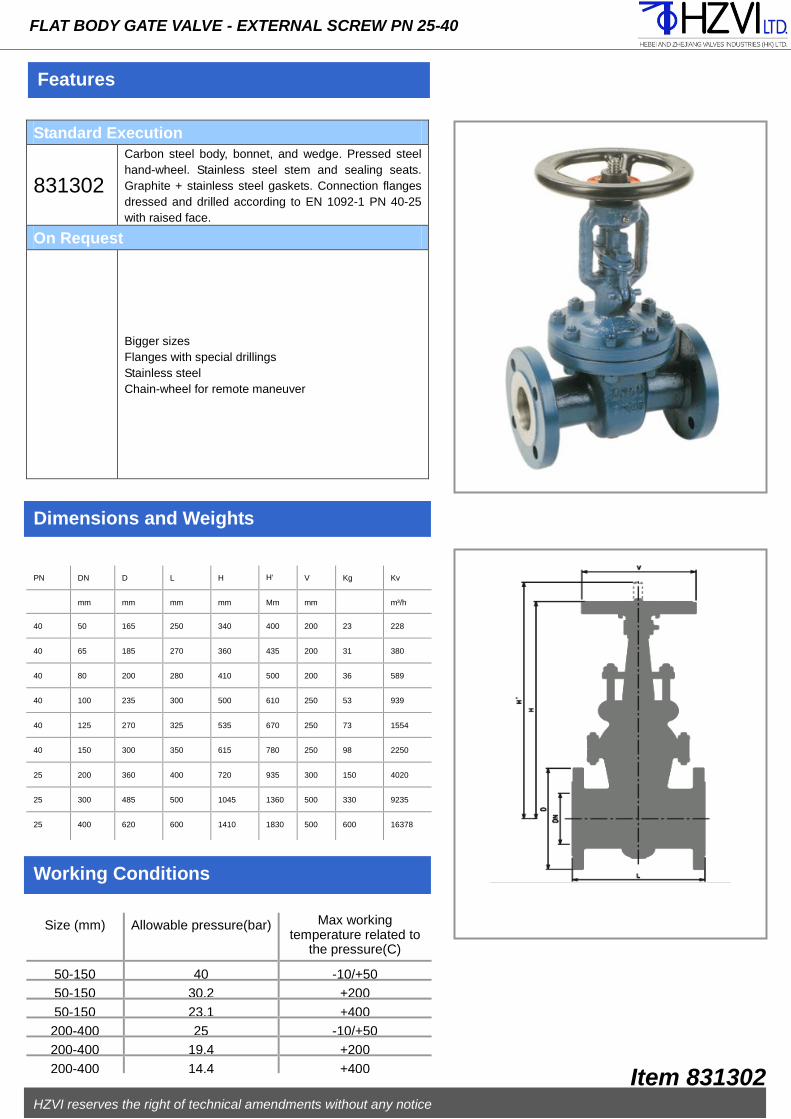
Features
FLAT BODY GATE VALVE - EXTERNAL SCREW PN 25-40
Standard Execution
831302
Carbon steel body, bonnet, and wedge. Pressed steel hand-wheel. Stainless steel stem and sealing seats. Graphite + stainless steel gaskets. Connection flanges dressed and drilled according to EN 1092-1 PN 40-25 with raised face.
On Request
Bigger sizes Flanges with special drillings Stainless steel Chain-wheel for remote maneuver
Dimensions and Weights
Working Conditions
PN DN D L H H' V Kg Kv
mm mm mm mm Mm mm m³/h
40 50 165 250 340 400 200 23 228
40 65 185 270 360 435 200 31 380
40 80 200 280 410 500 200 36 589
40 100 235 300 500 610 250 53 939
40 125 270 325 535 670 250 73 1554
40 150 300 350 615 780 250 98 2250
25 200 360 400 720 935 300 150 4020
25 300 485 500 1045 1360 500 330 9235
25 400 620 600 1410 1830 500 600 16378
Size (mm) Allowable pressure(bar) Max working temperature related to
the pressure(C)
50-150 40 -10/+50 50-150 30.2 +200 50-150 23.1 +400 200-400 25 -10/+50 200-400 19.4 +200 200-400 14.4 +400
HZVI reserves the right of technical amendments without any notice
Item 831302

PART NAME MATERIAL
1 BODY GP 240 GH STEEL
2 YOKE GP 240 GH STEEL
3 STEM STAINLESS STEEL
4 DISC DN 15-25 STAINLESS STEEL
4
DISC DN 32-250 STEE + ST.STEEL
5 SEAT STAINLESS STEEL
6 PACKING GRAPHITE
7 GASKET GRAPHITE + ST.STEEL
8 TIE-ROD STEEL
9 NUT STEEL
10 GLAND CARBON STEEL
11 BUSH STEEL
12 HAND-WHEEL PRESSED STEEL
13 NUT STEEL
Steel Construction
Installation Maintenance
Recommended Spare Parts
STREAMLINED FLOW VALVE WITH BELLOWS – EXTERNAL SCREW PN 63
Before to assemble the valve at the pipeline, open it until about
half-stroke. Check inside the body to be completely clean, possible
extraneous matters have to be removed in order to ensure a right
functioning. If compressed air is at your disposal, use it for a better
cleaning.
The counter-flanges of the pipeline must be parallel and have
aligned holes. Check the space between them, keeping into
account the gaskets and their flattering after bolts closing (it should
not be too much or too litter) and face to face tolerances as per
EN-558-1 standard.
In case of limited pressures, ask for springs with reduced thrust,
indicating the working pressure.
The valve must be assembled following the direction indicated by
the arrow on the body. Fix the valve in the right position at the
pipeline and remember to insert the gaskets between the flanges
centring them as much as possible on the raised face.
The raised faces have to be clean to allow a correct tightness.
Fit the bolts in flanges holes and tighten them maintaining a
diametrically opposed sequence (for a better deformation of the
gaskets). Check the right functioning of the valve with two or three
complete open-close operations.
Occasionally verify the sealing of the packing (7), in case of leakages tighten the
gland nuts (7).
To add more packing, when plant is not in pressure and temperature, loosen the
nuts (10), rise up the gland, fit new packing and tighten again gland (10).
If the gate valve is working, use the backseat obtained on the stem forcing the
opening maneuver; check if the backseat works (it is possible to find the
backseat worn out if the gate valve is installed since time) and act following the
above mentioned operations.
If the valve should leak from the seat, do not insist in closing with more strength
by the hand-wheel(12) because it is possible to damage more the sealing seats;
open and close again the valve in order to remove possible sediments.
If necessary the valve can be completely disassembled using standard tools.
Before to assemble it again, open the valve at two hand-wheel turns, check if the
sealing seats are carefully clean and not damaged; check if each part of the
gasket is integral, otherwise it is recommended to replace them.
Gasket (6) – Spring (7)
HZVI reserves the right of technical amendments without any notice
Item 831403
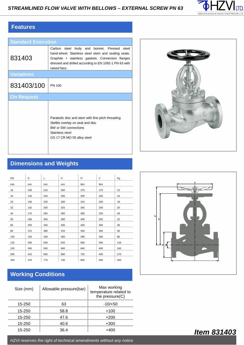
Features
STREAMLINED FLOW VALVE WITH BELLOWS – EXTERNAL SCREW PN 63
Standard Execution
831403
Carbon steel body and bonnet. Pressed steel
hand-wheel. Stainless steel stem and sealing seats.
Graphite + stainless gaskets. Connection flanges
dressed and drilled according to EN 1092-1 PN 63 with
raised face.
Variations
831403/100 PN 100
On Request
Parabolic disc and stem with fine pitch threading
Stellite overlay on seat and disc
BW or SW connections
Stainless steel
GS 17 CR MO 55 alloy steel
Dimensions and Weights
Working Conditions
DN D L H H’ V Kg
mm mm mm mm Mm Mm
15 105 210 260 275 175 10
20 130 230 285 300 200 16
25 140 230 300 315 200 18
32 155 250 325 345 200 20
40 170 260 365 385 250 28
50 180 300 385 405 250 32
65 205 340 405 435 300 48
80 215 380 420 450 300 56
100 150 430 460 495 300 86
125 295 500 520 560 300 126
150 345 550 600 645 400 160
200 415 650 660 725 400 270
250 470 775 730 805 500 450
Size (mm) Allowable pressure(bar) Max working temperature related to
the pressure(C)
15-250 63 -10/+50
15-250 58.8 +100
15-250 47.6 +200
15-250 40.6 +300
15-250 36.4 +400
HZVI reserves the right of technical amendments without any notice
Item 831403

PART NAME MATERIAL
1 BODY DN 15-50 P250 GH STEEL
1 BODY DN 16-250 GP 240 GH+N STEEL
2 STEM STAINLESS STEEL
3 DISC DN 15-100 STAINLESS STEEL
3 DISC DN 125-250 STEEL+ST.STEEL
4
SEAT STAINLESS STEEL
5 YOKE DN 15-50 P 250 GH STEEL
5 YOKE DN 65-250 GP 240 GH+N STEEL
6 BELLOWS STAINLESS STEEL
7 GLAND STEEL
8 STEM GUIDE-INDEX STEEL
9 BUSH DN 15-200 STEEL
9 BUSH 250 NODULAR CAST IRON
10 ANTIFRICTION BEARINGS TEMPERED STEEL
11 HAND-WHEEL STEEL
12 STOP HANDWHEEL NUT STEEL
13 ANTIFRICTION DISK STAINLESS STEEL
14 PACKNG CARBON-GRAPHITE
15 REGULATING NUT ZINC PLATED STEEL
16 RISE LIMITER ZINC PLATED STEEL
17 CAP STEEL
18 LUBRICATOR ZINC PLATED STEEL
19 STOP SCREW ZINC PLATED STEEL
20 GASKETS GRAPHITE+ST.STEEL
21 NUT STEEL
Steel Construction
Installation Maintenance
Recommended Spare Parts
STREAMLINED FLOW VALVE - EXTERNAL SCREW PN 40 WITH BELLOWS - MAINTENANCE FREE
Before to assemble the valve at the pipeline, open it until about
half-stroke. Check inside the body to be completely clean, possible
extraneous matters have to be removed in order to ensure a right
functioning. If compressed air is at your disposal, use it for a better
cleaning.
The counter-flanges of the pipeline must be parallel and have
aligned holes. Check the space between them; keeping into
account the gaskets and their flattering after bolts closing (it should
not be too much or too litter) and face to face tolerances as per
EN-558-1 standard.
The valve must be assembled following the direction indicated by
the arrow on the body. Fix the valve in the right position at the
pipeline and remember to insert the gaskets between the flanges
centering them as much as possible on the raised face.
The raised faces have to be clean to allow a correct tightness.
Fit the bolts in flanges holes and tighten them maintaining a
diametrically opposed sequence (for a better deformation of the
gaskets).Check the right functioning of the gate valve with two or
three complete open-close operations.
THIS KIND OF VALVE NEEDS NO MAINTENANCE SINCE THE BELLOWS
HAS BEEN TESTED FOR THOUSANDS MANOEUVRES.
The leakage of fluid from the stuffing box indicates the accidental breaking of the
bellows (6). Waiting to repair or replace the valve, tighten the gland nuts.
In order to add new packing when plant not in pressure neither temperature,
loosen the gland nuts, fit new packing and tighten again the nuts.
Using the backseat it is possible to add more packing when the plant is working,
unfasten completely the locking set screw (21) and the rise limiter (22) (if
proved), use the backseat on the stem forcing the opening maneuver, check its
functionality and act following the above mentioned operations. This must be
carried out within a short term from the bellows breaking since the fluid could
damage the functionality of the backseat.
If necessary the valve can be completely disassembled using standard tools.
It is economically advisable to repair the valve only for big sizes.
Before to assemble it again, open the valve at two hand-wheel turns, check if the
sealing seats are carefully clean and not damaged; check if each part of the
gaskets is integral, otherwise it is recommended to replace them. Functioning
instructions are supplied together with each valve.
Packing (14) – Gaskets (20)
HZVI reserves the right of technical amendments without any notice
Item 831491

Features
STREAMLINED FLOW VALVE - EXTERNAL SCREW PN 40 WITH BELLOWS MAINTENANCE FREE
Standard Execution
831491
Carbon steel body and yoke. Stainless steel stem,
bellows and sealing seats. Graphite + stainless steel
gaskets. Carbon steel hand wheel. The valve is
standard provided by: position indicator, safety
backseat on the stem, rise limiter, lubricator, locking set
screw. Connection flanges dressed and drilled
according to EN 1092-1 PN 40 with raised face.
Variations
831491/R Parabolic disc 831491/E
Balanced
disc
831491/T Interchangeable PTFE gasket on the disc(max 180℃)
831491/A SDNR disc(check + on/off function)
831491/RT Parabolic disc with interchangeable PTFE gasket(max
180℃)
On Request
Bigger sizes
Flanges with special drillings
Chain-wheel for remote maneuver
Pneumatic actuator S.A. or D.A. – electric actuator with
fittings
Padlock device
Stellite overlay on seat and disc
BW or SW connections
Dimensions and Weights
Working Conditions
DN D L H V Kg Kv
mm mm mm mm Mm m³/h
15 95 130 230 125 4.8 4.8
20 105 150 233 125 5.4 7.6
25 115 160 240 125 6.8 12.2
32 140 180 248 125 9.3 17.5
40 150 200 277 150 12.9 27.8
50 165 230 287 150 15.6 44.3
65 185 290 373 200 27 81
80 200 310 377 200 31 155.4
100 235 350 410 250 45 184.1
125 270 400 458 300 70 272.5
150 300 480 516 350 99 382.7
200 375 600 633 400 188 690.6
250 450 730 785 500 275 1086
Size (mm) Allowable pressure (bar) Max working temperature related to the pressure(C)
15-250 40 -10/+50
15-250 37.3 +100
15-250 30.2 +200
15-250 25.8 +300
15-250 23.1 +400
HZVI reserves the right of technical amendments without any notice
Item 831491

PART NAME MATERIAL
1 BODY DN 15-50 P 250 GH STEEL
1 BODY DN 65-250 GP 240 GH+N STEEL
2 SEAT STAINLESS STEEL
3 DISC DN 15-100 STAINLESS STEEL
3
DISC DN 125-250 STEE + ST.STEEL
4 SPRING ZINC PLATED STEEL
5 GASKET GRAPHITE + ST.STEEL
6 COVER CARBON STEEL
7 NUT STEEL
8 STUD STEEL
Steel Construction
Installation Maintenance
Recommended Spare Parts
FLOW CHECK VALVE PN 40
Before to assemble the valve at the pipeline, open it until about
half-stroke. Check inside the body to be completely clean, possible
extraneous matters have to be removed in order to ensure a right
functioning. If compressed air is at your disposal, use it for a better
cleaning.
The counter-flanges of the pipeline must be parallel and have
aligned holes. Check the space between them, keeping into
account the gaskets and their flattering after bolts closing(it should
not be too much or too litter) and face to face tolerances as per
EN-558-1 standard.
In case of limited pressures, ask for springs with reduced thrust,
indicating the working pressure.
The valve must be assembled following the direction indicated by
the arrow on the body. Fix the valve in the right position at the
pipeline and remember to insert the gaskets between the flanges
centring them as much as possible on the raised face.
The raised faces have to be clean to allow a correct tightness.
Fit the bolts in flanges holes and tighten them maintaining a
diametrically opposed sequence (for a better deformation of the
gaskets).
The sole possible leakage is the non-sealing of the seat normally due to the
wear of time or to possible extraneous matters in the pipeline.
To restore the sealing disassembled the valve: loosen the nuts(7), check the
seats conditions; if they are still integral, carefully clean them as well as the
sliding parts of the disc, of the guide-pin and of the spring(4). If the spring
damaged, replace it.
If necessary the valve can be completely disassembled using standard tools.
Before to assemble it again, check if the sealing seats are carefully dean and not
damaged; check if each part of the gasket (5) is integral, otherwise it is
recommended to replace it.
Gasket (5) – Spring (4)
HZVI reserves the right of technical amendments without any notice
Item 831506
Functioning
The valve works both horizontally and vertically but if the flow raise the disc.
In case of vertical installations, exclude the assembling with the flow direction
from top to bottom; in case of horizontal installation, keep the cover upwards.

Features
FLOW CHECK VALVE PN 40
Standard Execution
831506 Carbon steel, body, cover and disc. Stainless steel sealing
seats. Graphite + stainless steel gasket. Connection
flanges dressed and drilled according to EN 1092-1 PN 40
with raised face.
Variations
831506/T Interchangeable PTFE gasket on the disc(max 180C)
831506 Stainless steel Gx5 CrNiMo 19-11-2.
On Request
Bigger sizes
Flanges with special drillings
Stellite overlay on seat and disc
BW or SW connections
Dimensions and Weights
Working conditions
DN D L H Kg
mm mm mm mm
15 95 130 84 3.5
20 105 150 88 4.1
25 115 160 93 4.7
32 140 180 96 7.3
40 150 200 108 9.2
50 165 230 120 11.8
65 185 290 171 21
80 200 310 200 24
100 235 350 125 36
125 270 400 236 61
150 300 480 250 82
200 375 600 305 134
250 450 730 360 244
Size (mm) Allowable pressure(bar) Max working temperature related to
the pressure(C)
15-250 40 -10/+50
15-250 37.3 +100
15-250 30.2 +200
15-250 25.8 +300
15-250 23.1 +400
HZVI reserves the right of technical amendments without any notice
Item 831506

PART NAME MATERIAL
1 BODY GP 240 GH STEEL
2 COVER AS TM A 105STEEL
3 SEAT STAINLESS STEEL
4 DISC DN 15-25 STAINLESS STEEL
4
DISC DN 32-250 STEE + ST.STEEL
5 SPRING STEEL
6 GASKET GRAPHITE + ST.STEEL
7 NUT STEEL
8 NUT STEEL
Steel Construction
Installation Maintenance
Recommended Spare Parts
FLOW CHECK VALVE PN 63
Before to assemble the valve at the pipeline, open it until about
half-stroke. Check inside the body to be completely clean, possible
extraneous matters have to be removed in order to ensure a right
functioning. If compressed air is at your disposal, use it for a better
cleaning.
The counter-flanges of the pipeline must be parallel and have
aligned holes. Check the space between them, keeping into
account the gaskets and their flattering after bolts closing (it should
not be too much or too litter) and face to face tolerances as per
EN-558-1 standard.
In case of limited pressures, ask for springs with reduced thrust,
indicating the working pressure.
The valve must be assembled following the direction indicated by
the arrow on the body. Fix the valve in the right position at the
pipeline and remember to insert the gaskets between the flanges
centring them as much as possible on the raised face.
The raised faces have to be clean to allow a correct tightness.
Fit the bolts in flanges holes and tighten them maintaining a
diametrically opposed sequence (for a better deformation of the
gaskets).
The sole possible leakage is the non-sealing of the seat normally due to the
wear of time or to possible extraneous matters in the pipeline.
To restore the sealing disassembled the valve: loosen the nuts (7), check the
seats conditions (3); if they are still integral, carefully clean them as well as the
sliding parts of the disc, of the guide-pin and of the spring (5). If the spring
damaged, replace it.
If necessary the valve can be completely disassembled using standard tools.
Before to assemble it again, check if the sealing seats are carefully dean and not
damaged; check if each part of the gasket (6) is integral, otherwise it is
recommended to replace it.
Gasket (6) – Spring (5)
HZVI reserves the right of technical amendments without any notice
Item 831507
Functioning
The valve works both horizontally and vertically but if the flow raise the disc.
In case of vertical installations, exclude the assembling with the flow direction
from top to bottom; in case of horizontal installation, keep the cover upwards.

Features
FLOW CHECK VALVE PN 63
Standard Execution
831507 Carbon steel, body, cover and disc. Stainless steel
sealing seats. Graphite + carbon steel gasket.
Connection flanges dressed and drilled according to
EN 1092-1 PN 63 with raised face.
Variations
831507/100 PN 100
On Request
Stellite overlay on seat and disc
BW or SW connections
Stainless steel
GS 17 CR MO 55 alloy steel
Dimensions and Weights
Working Conditions
DN D L H Kg
mm mm mm mm
15 105 210 105 8
20 130 230 120 12
25 140 230 130 14
32 155 250 135 18
40 170 260 140 22
50 180 300 160 29
65 205 340 180 42
80 215 380 200 48
100 250 430 220 68
125 295 500 250 116
150 345 550 280 133
200 415 650 330 243
250 470 775 390 372
Size (mm) Allowable pressure(bar) Max working temperature related to
the pressure(C)
15-250 63 -10/+50
15-250 58.8 +100
15-250 47.6 +200
15-250 40.6 +300
15-250 36.4 +400
HZVI reserves the right of technical amendments without any notice
Item 831507

PART NAME MATERIAL
1 BODY GP 240 GH+N STEEL
2 COVER CARBON STEEL
3 TIE-ROD STEEL
4 NUT STEEL
5
GASKETS GRAPHITE+ST.STEEL
6 PIN STAINLESS STEEL
7 BODY SEAT STAINLESS STEEL
8 DISC SEAT STAINLESS STEEL
9 DISC CARBON STEEL
10 HINGE CARBON STEEL
11 STUD SCREW STEEL
12 NUT STEEL
Steel Construction
Installation Maintenance
Recommended Spare Parts
SWING CHECK VALVE PN 25
Before to assemble the valve at the pipeline, open it until about
half-stroke. Check inside the body to be completely clean, possible
extraneous matters have to be removed in order to ensure a right
functioning. If compressed air is at your disposal, use it for a better
cleaning.
The counter-flanges of the pipeline must be parallel and have
aligned holes. Check the space between them, keeping into
account the gaskets and their flattering after bolts closing (it should
not be too much or too litter) and face to face tolerances as per
EN-558-1 standard.
The valve must be assembled following the direction indicated by
the arrow on the body. Fix the valve in the right position at the
pipeline and remember to insert the gaskets between the flanges
centring them as much as possible on the raised face.
The raised faces have to be clean to allow a correct tightness.
Fit the bolts in flanges holes and tighten them maintaining a
diametrically opposed sequence (for a better deformation of the
gaskets).
The sole possible leakage is the non-sealing of the seat normally due to the
wear of time or to possible extraneous matters in the pipeline.
To restore the sealing disassembled the valve: loosen the nuts (4), take away
the cover (2), loosen and take away the pin (6) by the external nut, unscrew the
nut (12) and replace the disc.
If necessary the valve can be completely disassembled using standard tools.
Before to assemble it again, open the valve at two hand-wheel turns, check if the
sealing seats are carefully clean and not damaged; check if each part of the
gaskets (5) is integral, otherwise it is recommended to replace it.
Gasket (5) – Disc (9)
HZVI reserves the right of technical amendments without any notice
Item 831508
Functioning
The valve works both horizontally and vertically but if the flow raise the disc.
In case of vertical installations, exclude the assembling with the flow direction
from top to bottom; in case of horizontal installation, keep the cover upwards.

Features
SWING CHECK VALVE PN 25
Standard Execution
831508 Carbon steel, body, cover and disc. Stainless steel sealing
seats. Graphite + stainless steel gasket. Connection flanges
dressed and drilled according to EN 1092-1 PN 25 with
raised face.
Variations
831508/
PN 16.
On Request
Flanges with special drillings
Stainless steel
Dimensions and Weights
Working Conditions
DN D L H Kg Kv
mm mm mm mm m³/h
50 165 200 160 15 80
65 185 240 170 24 120
80 200 260 175 28 230
100 235 300 195 38 350
125 270 350 210 58 880
150 300 400 240 96 1050
200 360 500 280 131 1410
250 425 600 320 212 1850
300 485 700 365 273 2670
350 555 800 425 440 3820
400 620 900 440 465 4880
Size (mm) Allowable pressure(bar) Max working temperature related to
the pressure(C)
50-400 25 -10/+50
50-400 23.3 +100
50-400 19.4 +200
50-400 16.1 +300
50-400 14.4 +400
HZVI reserves the right of technical amendments without any notice
Item 831508

PART NAME MATERIAL
1 BODY GP 240 GH+N STEEL
2 COVER CARBON STEEL
3 TIE-ROD STEEL
4 NUT STEEL
5
GASKETS GRAPHITE+ST.STEEL
6 PIN STAINLESS STEEL
7 BODY SEAT STAINLESS STEEL
8 DISC SEAT STAINLESS STEEL
9 DISC CARBON STEEL
10 HINGE CARBON STEEL
11 STUD STEEL
12 NUT STEEL
Steel Construction
Installation Maintenance
Recommended Spare Parts
SWING CHECK VALVE PN 40
Before to assemble the valve at the pipeline, open it until about
half-stroke. Check inside the body to be completely clean, possible
extraneous matters have to be removed in order to ensure a right
functioning. If compressed air is at your disposal, use it for a better
cleaning.
The counter-flanges of the pipeline must be parallel and have
aligned holes. Check the space between them, keeping into
account the gaskets and their flattering after bolts closing (it should
not be too much or too litter) and face to face tolerances as per
EN-558-1 standard.
The valve must be assembled following the direction indicated by
the arrow on the body. Fix the valve in the right position at the
pipeline and remember to insert the gaskets between the flanges
centring them as much as possible on the raised face.
The raised faces have to be clean to allow a correct tightness.
Fit the bolts in flanges holes and tighten them maintaining a
diametrically opposed sequence (for a better deformation of the
gaskets).
The sole possible leakage is the non-sealing of the seat normally due to the
wear of time or to possible extraneous matters in the pipeline.
To restore the sealing disassembled the valve: loosen the nuts (4), take away
the cover (2), loosen and take away the pin (6) by the external nut, unscrew the
nut (12) and replace the disc.
If necessary the valve can be completely disassembled using standard tools.
Before to assemble it again, open the valve at two hand-wheel turns, check if the
sealing seats are carefully clean and not damaged; check if each part of the
gaskets(5) is integral, otherwise it is recommended to replace it.
Gasket (5) – Disc (9)
HZVI reserves the right of technical amendments without any notice
Item 831509
Functioning
The valve works both horizontally and vertically but if the flow raise the disc.
In case of vertical installations, exclude the assembling with the flow direction
from top to bottom; in case of horizontal installation, keep the cover upwards.

Features
SWING CHECK VALVE PN 40
Standard Execution
831509 Carbon steel, body, cover and disc. Stainless steel sealing
seats. Graphite + stainless steel gasket. Connection flanges
dressed and drilled according to EN 1092-1 PN 40 with
raised face.
On Request
Flanges with special drillings
Stainless steel
Dimensions and Weights
Working Conditions
DN D L H Kg Kv
mm mm mm mm m³/h
50 165 230 160 20 78
80 200 310 175 33 225
100 235 350 215 46 340
125 270 400 230 65 870
150 300 480 240 95 1040
200 375 600 290 165 1400
250 450 730 320 230 1840
300 515 850 395 380 2660
350 580 980 435 500 3810
400 660 1100 450 580 4860
Size (mm) Allowable pressure(bar) Max working temperature related to
the pressure(C)
50-400 40 -10/+50
50-400 37.3 +100
50-400 30.2 +200
50-400 25.8 +300
50-400 23.1 +400
HZVI reserves the right of technical amendments without any notice
Item 831509

PART NAME MATERIAL
1 BODY CARBON STEEL
2 CLAPET STAINLESS STEEL
3 BODY O-RING DUNA N - VITON
4 DISC O-RING DUNA N – VITON
5
LIFTING EYE BOLT CARBON STEEL
Carbon Steel Construction
Installation Maintenance
Recommended Spare Parts
SWING CHECK WAFER VALVE PN 16
Before to assemble the valve at the pipeline check inside the body
to be completely clean, possible impurities have to be removed in
order to ensure a right functioning. If compressed air is at your
disposal, use it for a better cleaning.
The counter-flanges of the pipeline must be parallel and aligned
holes. Check the space between them, keeping into account the
gaskets and their flattering after nuts closing.
Do not weld any flange at the pipeline when the valve is already
assembled.
Fit the tie-rods in flanges holes, necessarily welding neck type, and
tighten them maintaining a diametrically opposed sequence (for a
better deformation of the O-rings).
The non sealing of the disc seat is exclusively due to the wear of time of the
o-ring gaskets..
When it is necessary to replace one gasket, it is advisable to replace them all.
Check that O-rings housing is perfect and clean.
O-rings (3-4)
HZVI reserves the right of technical amendments without any notice
Item 831510
Functioning
The valve works both horizontally and vertically but if the flow raise the disc.
In case of vertical installations, exclude the assembling with the flow direction
from top to bottom.

Features
SWING CHECK WAFER VALVE PN 16
Standard Execution
881510 Cast iron body. Bronze swing. Stainless steel pin and spring. NBR gasket. Suitable to be assembled between flanges PN 6/10/16 ad ANSI 150.
On Request
Bigger sizes Fully made of stainless steel With spring VITON, EPDM, PTFE O-rings PN 25-250 series ANSI 300-1500 RF/RTJ series
Dimensions and Weights
Working Conditions
DN D L P Kg Kv
mm mm mm mm m³/h
40 94 14 19 0.65 11.6
50 109 14 25 1 18.9
65 129 14 38 1.3 42.2
80 144 14 46 1.6 67.2
100 164 14 71 2 258.6
125 195 16 95 3 547.4
150 221 19 114 5 725
250 331 32 188 15 1896
300 386 38 216 25 2121
Size (mm) Allowable pressure (bar) Max working temperature related to the pressure(C)
40-300 16 -40/+100 (BUNA) 40-300 16 -20/+200 (VITON)
HZVI reserves the right of technical amendments without any notice
Item 831510

PART NAME MATERIAL
1 BODY ASTM A 105 STEEL
2 DISK DN 40-100 STAINLESS STEEL
2 DISK DN 125-200 STEEL + ST. STEEL
3 SEAT DN 40-100 STAINLESS STEEL
3
SEAT DN 125-200 STEEL + ST. STEEL
4 SPRING STAINLESS STEEL
5 GUIDE STAINLESS STEEL
6 QUADDER PPS
7 RING STAINLESS STEEL
8 WASHER STAINLESS STEEL
9 SEAT RING REQUEST
10 RING STAINLESS STEEL
11 TIE-ROD STAINLESS STEEL
12 SCREW STAINLESS STEEL
13 SCREW STAINLESS STEEL
Carbon Steel Construction
Installation Maintenance
Recommended Spare Parts
DISC CHECK WAFER VALVE PN 16
Before to assemble the valve at the pipeline check inside the body
to be completely clean, possible impurities have to be removed in
order to ensure a right functioning. If compressed air is at your
disposal, use it for a better cleaning.
The counter-flanges of the pipeline must be parallel and aligned
holes. Check the space between them, keeping into account the
gaskets and their flattering after nuts closing.
Do not weld any flange at the pipeline when the valve is already
assembled.
Fit the tie-rods in flanges holes, necessarily welding neck type, and
tighten them maintaining a diametrically opposed sequence (for a
better deformation of the O-rings).
The non sealing of the disc seat is exclusively due to the wear of time of the
sealing ring (9).
If the non sealing is due to impurities in the pipeline, deposited on the seats,
disassemble the valve from the plant and remove them.
Due to its shape it is not advisable to disassemble the valve to repair the
sealing seats, in case they are damaged; therefore it is necessary to repair
the valve at a factory, in order to check again the valve once repaired by
appropriate machineries.
Not applicable
HZVI reserves the right of technical amendments without any notice
Item 831601
Functioning
The valve works both horizontally and vertically but if the flow raise the disc.
In case of vertical installations, exclude the assembling with the flow direction
from top to bottom.

Features
DISC CHECK WAFER VALVE PN 16
Standard Execution
831601 Galvanized steel body. Stainless steel disk, seat, spring and guides. Suitable to be assembled between flanges PN 10/16 and ANSI 150.
Variations
831601 AISI 316 stainless steel body
On Request
EPDM, BUNA, VITON, PTFE sealing ring PN 25-40 series
Dimensions and Weights
Working Conditions
DN D L A Kg Kv
mm mm mm mm m³/h
40 78 31.5 104 0.5 23
50 98 40 120 1.3 36
65 115 46 140 1.75 65
80 137 50 161 2.7 78
100 158 60 186 4.3 116
125 194 90 - 8.4 200
150 220 106 - 11.5 305
200 275 140 - 20.4 540
Size (mm) Allowable pressure (bar) Max working temperature related to the pressure(C)
40-200 16 -40/+90 (BUNA) 40-200 16 -40/+120 (EPDM) 40-200 16 -20/+180 (VITON) 40-200 16 -40/+180 (PTFE)
HZVI reserves the right of technical amendments without any notice
Item 831601
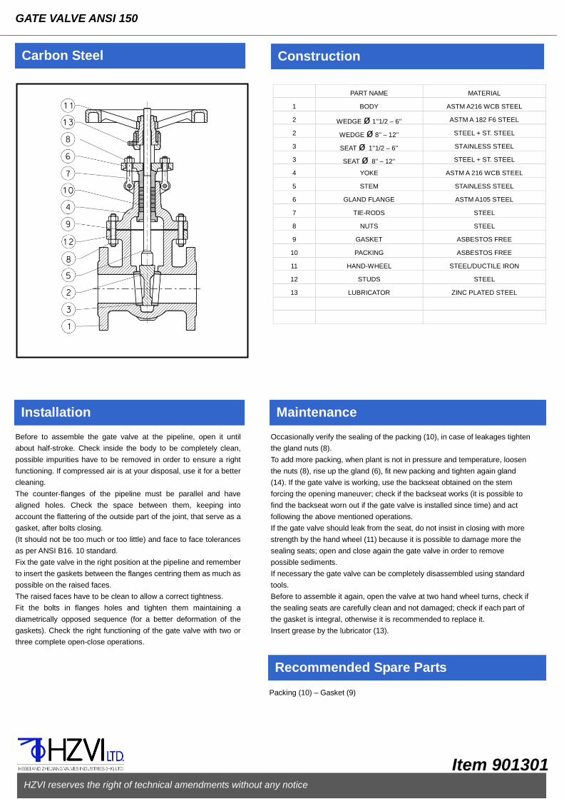
PART NAME MATERIAL
1 BODY ASTM A216 WCB STEEL
2 WEDGE ø 1’’1/2 – 6’’ ASTM A 182 F6 STEEL
2 WEDGE ø 8’’ – 12’’ STEEL + ST. STEEL
3 SEAT ø 1’’1/2 – 6’’ STAINLESS STEEL
3 SEAT ø 8’’ – 12’’ STEEL + ST. STEEL
4 YOKE ASTM A 216 WCB STEEL
5 STEM STAINLESS STEEL
6 GLAND FLANGE ASTM A105 STEEL
7 TIE-RODS STEEL
8 NUTS STEEL
9 GASKET ASBESTOS FREE
10 PACKING ASBESTOS FREE
11 HAND-WHEEL STEEL/DUCTILE IRON
12 STUDS STEEL
13 LUBRICATOR ZINC PLATED STEEL
Carbon Steel Construction
Installation Maintenance
Recommended Spare Parts
GATE VALVE ANSI 150
Before to assemble the gate valve at the pipeline, open it until
about half-stroke. Check inside the body to be completely clean,
possible impurities have to be removed in order to ensure a right
functioning. If compressed air is at your disposal, use it for a better
cleaning.
The counter-flanges of the pipeline must be parallel and have
aligned holes. Check the space between them, keeping into
account the flattering of the outside part of the joint, that serve as a
gasket, after bolts closing.
(It should not be too much or too little) and face to face tolerances
as per ANSI B16. 10 standard.
Fix the gate valve in the right position at the pipeline and remember
to insert the gaskets between the flanges centring them as much as
possible on the raised faces.
The raised faces have to be clean to allow a correct tightness.
Fit the bolts in flanges holes and tighten them maintaining a
diametrically opposed sequence (for a better deformation of the
gaskets). Check the right functioning of the gate valve with two or
three complete open-close operations.
Occasionally verify the sealing of the packing (10), in case of leakages tighten
the gland nuts (8).
To add more packing, when plant is not in pressure and temperature, loosen
the nuts (8), rise up the gland (6), fit new packing and tighten again gland
(14). If the gate valve is working, use the backseat obtained on the stem
forcing the opening maneuver; check if the backseat works (it is possible to
find the backseat worn out if the gate valve is installed since time) and act
following the above mentioned operations.
If the gate valve should leak from the seat, do not insist in closing with more
strength by the hand wheel (11) because it is possible to damage more the
sealing seats; open and close again the gate valve in order to remove
possible sediments.
If necessary the gate valve can be completely disassembled using standard
tools.
Before to assemble it again, open the valve at two hand wheel turns, check if
the sealing seats are carefully clean and not damaged; check if each part of
the gasket is integral, otherwise it is recommended to replace it.
Insert grease by the lubricator (13).
Packing (10) – Gasket (9)
HZVI reserves the right of technical amendments without any notice
Item 901301

Features
GATE VALVE ANSI 150
Standard Execution
901301 Carbon steel body and yoke. Stainless steel stem, seats and wedge until ø 6’’. Asbestos free gaskets. Connection flanges dressed and drilled according to ANSI B16.5 150RF.
On Request
Bigger sizes AISI 3 16 e WC6 stainless steel Chain-wheel for remote maneuver BW connections Stellite overlay on seats and wedge Micro-switches Gearbox Lantern
Dimensions and Weights
Working Conditions
DN D L L(BW) H V Kg
mm mm mm 。 mm
1’’1/2 127 165 165 350 175 12
2’’ 152 178 216 380 200 16
2’’1/2 178 191 241 445 200 24
3’’ 190 203 283 490 225 27
4’’ 229 229 305 580 250 44
5’’ 254 254 381 715 250 60
6’’ 279 267 403 810 350 75
8’’ 343 292 419 1010 400 140
10’’ 406 330 457 1330 450 190
12’’ 483 356 502 1510 450 284
Size (inch) Allowable pressure(bar) Max working temperature related to
the pressure(C)
1’’1/2-12’’ 51 -10/+38 1’’1/2-12’’ 46.5 +93 1’’1/2-12’’ 41.4 +260 1’’1/2-12’’ 18.6 +454
HZVI reserves the right of technical amendments without any notice
Item 901301

PART NAME MATERIAL
1 BODY ASTM A216 WCB STEEL
2 WEDGE ø 1’’1/2 – 6’’ ASTM A 182 F6 STEEL
2 WEDGE ø 10’’ – 12’’ STEEL + ST. STEEL
3 SEAT ø 1’’1/2 – 6’’ STAINLESS STEEL
3 SEAT ø10’’ – 12’’ STEEL + ST. STEEL
4 YOKE ASTM A 216 WCB STEEL
5 STEM STAINLESS STEEL
6 GLAND FLANGE ASTM A105 STEEL
7 TIE-RODS STEEL
8 NUTS STEEL
9 GASKET ASBESTOS FREE
10 PACKING ASBESTOS FREE
11 HANDWHEEL STEEL/DUCTILE IRON
12 STUDS STEEL
13 LUBRICATOR ZINC PLATED STEEL
Carbon Steel Construction
Installation Maintenance
Recommended Spare Parts
GATE VALVE ANSI 300
Before to assemble the gate valve at the pipeline, open it until
about half-stroke. Check inside the body to be completely clean,
possible impurities have to be removed in order to ensure a right
functioning. If compressed air is at your disposal, use it for a better
cleaning.
The counter-flanges of the pipeline must be parallel and have
aligned holes. Check the space between them, keeping into
account the flattering of the outside part of the joint, that serve as a
gasket, after bolts closing.
(It should not be too much or too little) and face to face tolerances
as per ANSI B16. 10 standard.
Fix the gate valve in the right position at the pipeline and remember
to insert the gaskets between the flanges centring them as much as
possible on the raised faces.
The raised faces have to be clean to allow a correct tightness.
Fit the bolts in flanges holes and tighten them maintaining a
diametrically opposed sequence (for a better deformation of the
gaskets). Check the right functioning of the gate valve with two or
three complete open-close operations.
Occasionally verify the sealing of the packing (10), in case of leakages tighten
the gland nuts (8).
To add more packing, when plant is not in pressure and temperature, loosen
the nuts (8), rise up the gland (6), fit new packing and tighten again gland
(14). If the gate valve is working, use the backseat obtained on the stem
forcing the opening maneuver; check if the backseat works (it is possible to
find the backseat worn out if the gate valve is installed since time) and act
following the above mentioned operations.
If the gate valve should leak from the seat, do not insist in closing with more
strength by the hand wheel (11) because it is possible to damage more the
sealing seats; open and close again the gate valve in order to remove
possible sediments.
If necessary the gate valve can be completely disassembled using standard
tools.
Before to assemble it again, open the valve at two hand wheel turns, check if
the sealing seats are carefully clean and not damaged; check if each part of
the gasket is integral, otherwise it is recommended to replace it.
Insert grease by the lubricator (13).
Packing (10) – Gasket (9)
HZVI reserves the right of technical amendments without any notice
Item 901303

Features
GATE VALVE ANSI 300
Standard Execution
901303 Carbon steel body and yoke. Stainless steel stem, seats and wedge until ø 6’’. Asbestos free gaskets. Connection flanges dressed and drilled according to ANSI B16.5 300RF.
On Request
Bigger sizes AISI 3 16 e WC6 stainless steel Chain-wheel for remote maneuver BW connections Stellite overlay on seats and wedge Micro-switches Gearbox Lantern
Dimensions and Weights
Working Conditions
DN D L H V Kg
mm mm 。 mm
1’’1/2 156 191 420 175 19
2’’ 165 216 460 200 23
2’’1/2 190 241 525 225 38
3’’ 210 283 580 250 44
4’’ 254 305 670 250 67
5’’ 279 381 795 350 110
6’’ 318 403 890 400 135
8’’ 381 419 1090 450 225
10’’ 444 457 1410 500 330
12’’ 521 502 1560 500 480
Size (inch) Allowable pressure(bar) Max working temperature related to
the pressure(C)
1’’1/2-12’’ 51 -10/+38 1’’1/2-12’’ 46.5 +93 1’’1/2-12’’ 41.4 +260 1’’1/2-12’’ 18.6 +454
HZVI reserves the right of technical amendments without any notice
Item 901303

PART NAME MATERIAL
1 BODY ASTM A216 WCB STEEL
2 WEDGE ø 2’’ – 6’’ ASTM A 182 F6 STEEL
2 WEDGE ø 8’’ – 12’’ STEEL + ST. STEEL
3 SEAT ø 2’’ – 6’’ STAINLESS STEEL
3 SEAT ø 8’’ – 12’’ STEEL + ST. STEEL
4 YOKE ASTM A 216 WCB STEEL
5 STEM STAINLESS STEEL
6 GLAND FLANGE ASTM A105 STEEL
7 TIE-RODS STEEL
8 NUTS STEEL
9 GASKET ASBESTOS FREE
10 PACKING ASBESTOS FREE
11 HAND-WHEEL STEEL/DUCTILE IRON
12 STUDS STEEL
13 LUBRICATOR ZINC PLATED STEEL
Carbon Steel Construction
Installation Maintenance
Recommended Spare Parts
GATE VALVE ANSI 600
Before to assemble the gate valve at the pipeline, open it until
about half-stroke. Check inside the body to be completely clean,
possible impurities have to be removed in order to ensure a right
functioning. If compressed air is at your disposal, use it for a better
cleaning.
The counter-flanges of the pipeline must be parallel and have
aligned holes. Check the space between them, keeping into
account the flattering of the outside part of the joint, that serve as a
gasket, after bolts closing.
(It should not be too much or too little) and face to face tolerances
as per ANSI B16. 10 standard.
Fix the gate valve in the right position at the pipeline and remember
to insert the gaskets between the flanges centring them as much as
possible on the raised faces.
The raised faces have to be clean to allow a correct tightness.
Fit the bolts in flanges holes and tighten them maintaining a
diametrically opposed sequence (for a better deformation of the
gaskets). Check the right functioning of the gate valve with two or
three complete open-close operations.
Occasionally verify the sealing of the packing (10), in case of leakages tighten
the gland nuts (8).
To add more packing, when plant is not in pressure and temperature, loosen
the nuts (8), rise up the gland (6), fit new packing and tighten again gland
(14). If the gate valve is working, use the backseat obtained on the stem
forcing the opening maneuver; check if the backseat works (it is possible to
find the backseat worn out if the gate valve is installed since time) and act
following the above mentioned operations.
If the gate valve should leak from the seat, do not insist in closing with more
strength by the hand wheel (11) because it is possible to damage more the
sealing seats; open and close again the gate valve in order to remove
possible sediments.
If necessary the gate valve can be completely disassembled using standard
tools.
Before to assemble it again, open the valve at two hand wheel turns, check if
the sealing seats are carefully clean and not damaged; check if each part of
the gasket is integral, otherwise it is recommended to replace it.
Insert grease by the lubricator (13).
Packing (10) – Gasket (9)
HZVI reserves the right of technical amendments without any notice
Item 901306

Features
GATE VALVE ANSI 600
Standard Execution
901306 Carbon steel body and yoke. Stainless steel stem, seats and wedge until ø 6’’. Asbestos free gaskets. Connection flanges dressed and drilled according to ANSI B16.5 600RF.
On Request
Bigger sizes AISI 3 16 e WC6 stainless steel Chain-wheel for remote maneuver BW connections Stellite overlay on seats and wedge Micro-switches Gearbox Lantern
Dimensions and Weights
Working Conditions
DN D L H V Kg
mm mm mm mm
2’’ 165 292 420 250 44
3’’ 210 356 575 300 80
4’’ 273 432 690 400 145
6’’ 356 559 900 500 309
8’’ 419 660 1070 550 470
10’’ 508 787 1280 600 720
12’’ 559 838 1460 700 1108
Size (inch) Allowable pressure(bar) Max working temperature related to
the pressure(C)
2’’-12’’ 102 -10/+38 2’’-12’’ 93.1 +93 2’’-12’’ 82.7 +260 2’’-12’’ 36.9 +454
HZVI reserves the right of technical amendments without any notice
Item 901306

PART NAME MATERIAL
1 BODY GX5CrNiMo 19-11-2
2 STEM STAINLESS STEEL
3 DISC STAINLESS STEEL
4
SEAT STAINLESS STEEL
5 YOKE GX5CrNiMo 19-11-2
7 BELLOWS STAINLESS STEEL
8 GLAND STAINLESS STEEL
9 BUSH DN 15-200 STEEL
9 BUSH DN 250 NODULAR CAST IRON
10 ANTIFRICTION BEARINGS TEMPERED STEEL
11 HANDWHEEL STEEL
12 STOP HANDWHEEL NUT ZINC PLATED STEEL
13 ANTIFRICTION DISK STAINLESS STEEL
14 PACKNG CARBON-GRAPHITE
15 REGULATING NUT ZINC PLATED STEEL
16 RISE LIMITER ZINC PLATED STEEL
17 CAP ZINC PLATED STEEL
18 LUBRICATOR ZINC PLATED STEEL
19 STOP SCREW ZINC PLATED STEEL
20 GASKETS GRAPHITE+ST.STEEL
21 NUT STEEL
Stainless Steel Construction
Installation Maintenance
Recommended Spare Parts
STREAMLINED FLOW VALVE - EXTERNAL SCREW PN 40 WITH BELLOWS - MAINTENANCE FREE
Before to assemble the valve at the pipeline, open it until about
half-stroke. Check inside the body to be completely clean, possible
extraneous matters have to be removed in order to ensure a right
functioning. If compressed air is at your disposal, use it for a better
cleaning.
The counter-flanges of the pipeline must be parallel and have
aligned holes. Check the space between them, keeping into
account the gaskets and their flattering after bolts closing (it should
not be too much or too litter) and face to face tolerances as per
EN-558-1 standard.
The valve must be assembled following the direction indicated by
the arrow on the body. Fix the valve in the right position at the
pipeline and remember to insert the gaskets between the flanges
centering them as much as possible on the raised face.
The raised faces have to be clean to allow a correct tightness.
Fit the bolts in flanges holes and tighten them maintaining a
diametrically opposed sequence (for a better deformation of the
gaskets).Check the right functioning of the gate valve with two or
three complete open-close operations.
THIS KIND OF VALVE NEEDS NO MAINTENANCE SINCE THE BELLOWS
HAS BEEN TESTED FOR THOUSANDS MANOEUVRES.
The leakage of fluid from the stuffing box indicate the accidental breaking of the
bellows (6). Waiting to repair or replace the valve, tighten the gland nuts.
In order to add new packing when plant not in pressure neither temperature,
loosen the gland nuts, fit new packing and tighten again the nuts.
Using the backseat it is possible to add more packing when the plant is working,
unfasten completely the locking set screw(21) and the rise limiter(22) (if proved),
use the backseat on the stem forcing the opening maneuver, check its
functionality and act following the above mentioned operations. This must be
carried out within a short term from the bellows breaking since the fluid could
damage the functionality of the backseat.
If necessary the valve can be completely disassembled using standard tools.
It is economically advisable to repair the valve only for big sizes.
Before to assemble it again, open the valve at two hand wheel turns, check if the
sealing seats are carefully clean and not damaged; check if each part of the
gaskets is integral, otherwise it is recommended to replace them. Functioning
instructions are supplied together with each valve.
Packing (14) – Gaskets (20)
HZVI reserves the right of technical amendments without any notice
Item 951402

Features
STREAMLINED FLOW VALVE - EXTERNAL SCREW PN 40 WITH BELLOWS MAINTENANCE FREE
Standard Execution
951402
Stainless steel body and yoke, stem, bellows and sealing
seats. Graphite + stainless steel gaskets. Carbon steel
hand wheel. The valve is standard provided by: position
indicator, safety backseat on the stem, rise limiter,
lubricator, locking set screw. Connection flanges dressed
and drilled according to EN 1092-1 PN 40 with raised
face.
Variations
951402/R Parabolic
disc 951402/E
Balanced disc
951402/T Interchangeable PTFE gasket on the disc(max 180℃)
951402/A SDNR disc(check + on/off function)
951402/RT Parabolic disc with interchangeable PTFE gasket(max
180℃)
On Request
Bigger sizes
Flanges with special drillings
Chain-wheel for remote maneuver
Pneumatic actuator S.A. or D.A. – electric actuator with
fittings
Padlock device
Stellite overlay on seat and disc
BW or SW connections
Dimensions and Weights
Working Conditions
DN D L H V Kg Kv
mm mm mm mm Mm m³/h
15 95 130 230 125 4.6 4.8
20 105 150 233 125 5.4 7.6
25 115 160 240 125 6.6 12.2
32 140 180 248 125 8.2 17.5
40 150 200 277 150 11.4 27.8
50 165 230 287 150 14.4 44.3
65 185 290 373 200 26.2 81
80 200 310 377 200 30.6 155.4
100 235 350 410 250 47.4 184.1
125 270 400 458 300 66.3 272.5
150 300 480 516 350 97.8 382.7
200 375 600 633 400 188 690.6
250 450 730 785 500 275 1086
Size (mm) Allowable pressure (bar) Max working temperature related to the pressure(C)
15-250 40 -10/+50
15-250 37.3 +100
15-250 31.2 +200
15-250 27.6 +300
15-250 25.6 +400
HZVI reserves the right of technical amendments without any notice
Item 951402

PART NAME MATERIAL
1 BODY NYLON
2 COVER NEOPRENE RUBBER
3 LINING STEEL WIRE
4 FLANGE ZINC PLATED STEEL
EPDM Construction
Installation Maintenance
Recommended Spare Parts
FLANGED ELASTIC EXPANSIONS JOINT
Before to assemble the joint at the pipeline check inside the body to
be completely clean, possible impurities have to be removed in
order to ensure a right functioning. If compressed air is at your
disposal, use it for a better cleaning.
the counter-flanges of the pipeline must be parallel and have
aligned holes. Check the space between them, keeping into
account the flattering of the outside part of the joint, that serve as a
gasket, after bolts closing.
Fit the bolts in flanges holes and tighten them maintaining a
diametrically opposed sequence (for a better deformation of the
outside part of the joint).
NOTA: in case of strong and continuous stresses it is advisable to
employ stroke limiter for joints.
This type of joints needs no maintenance.
Not applicable
HZVI reserves the right of technical amendments without any notice
Item 991001
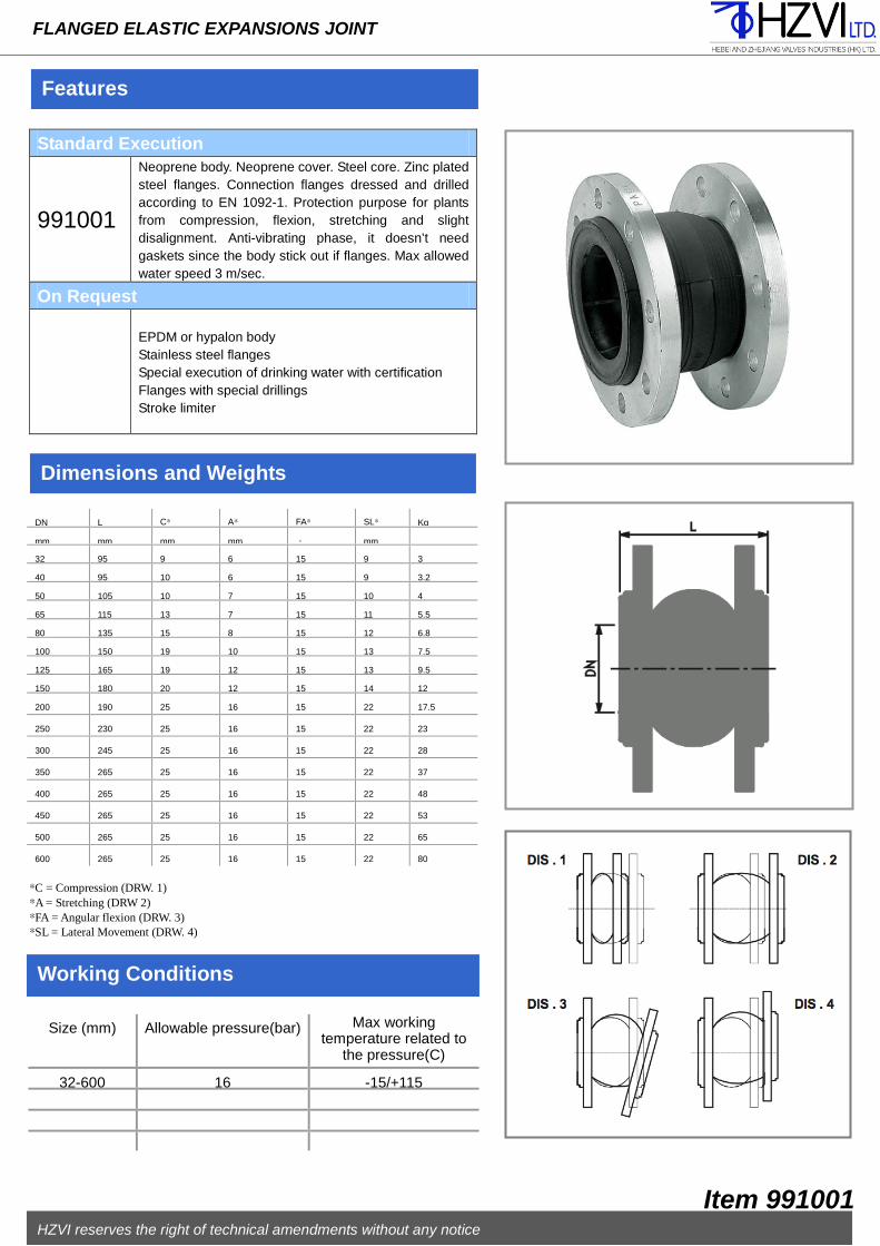
Features
FLANGED ELASTIC EXPANSIONS JOINT
Standard Execution
991001
Neoprene body. Neoprene cover. Steel core. Zinc plated steel flanges. Connection flanges dressed and drilled according to EN 1092-1. Protection purpose for plants from compression, flexion, stretching and slight disalignment. Anti-vibrating phase, it doesn’t need gaskets since the body stick out if flanges. Max allowed water speed 3 m/sec.
On Request
EPDM or hypalon body Stainless steel flanges Special execution of drinking water with certification Flanges with special drillings Stroke limiter
Dimensions and Weights
Working Conditions
DN L C* A* FA* SL* Kg
mm mm mm mm 。 mm
32 95 9 6 15 9 3
40 95 10 6 15 9 3.2
50 105 10 7 15 10 4
65 115 13 7 15 11 5.5
80 135 15 8 15 12 6.8
100 150 19 10 15 13 7.5
125 165 19 12 15 13 9.5
150 180 20 12 15 14 12
200 190 25 16 15 22 17.5
250 230 25 16 15 22 23
300 245 25 16 15 22 28
350 265 25 16 15 22 37
400 265 25 16 15 22 48
450 265 25 16 15 22 53
500 265 25 16 15 22 65
600 265 25 16 15 22 80
Size (mm) Allowable pressure(bar) Max working temperature related to
the pressure(C)
32-600 16 -15/+115
HZVI reserves the right of technical amendments without any notice
Item 991001
*C = Compression (DRW. 1) *A = Stretching (DRW 2) *FA = Angular flexion (DRW. 3) *SL = Lateral Movement (DRW. 4)

Hong Kong (Headquarter) Flat 2108, 21F, CC WU Building 308, Hennessy Road Wan Chai - Hong Kong
Tel.: +852 3568 2257 Fax: +852 2125 4982
[email protected] General Enquiries [email protected] Sales Enquires [email protected] Certificates Wenzhou - Zhejiang - P.R. China
Gongye 2nd Road Yongjia, Wenzhou, Zhejiang, P.R. China Shijiazhuang - Hebei - P.R. China
308 National Road Ningjin, Xingtai, Hebei, P.R. China


