Embed Size (px)
Citation preview
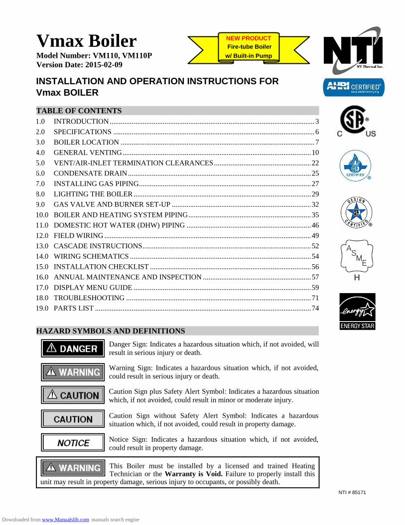
Vmax Boiler Model Number: VM110, VM110P
Version Date: 2015-02-09
INSTALLATION AND OPERATION INSTRUCTIONS FOR
Vmax BOILER
TABLE OF CONTENTS
1.0 INTRODUCTION ................................................................................................................ 3
2.0 SPECIFICATIONS .............................................................................................................. 6
3.0 BOILER LOCATION .......................................................................................................... 7
4.0 GENERAL VENTING ....................................................................................................... 10
5.0 VENT/AIR-INLET TERMINATION CLEARANCES ..................................................... 22
6.0 CONDENSATE DRAIN .................................................................................................... 25
7.0 INSTALLING GAS PIPING .............................................................................................. 27
8.0 LIGHTING THE BOILER ................................................................................................. 29
9.0 GAS VALVE AND BURNER SET-UP ............................................................................ 32
10.0 BOILER AND HEATING SYSTEM PIPING ................................................................... 35
11.0 DOMESTIC HOT WATER (DHW) PIPING .................................................................... 46
12.0 FIELD WIRING ................................................................................................................. 49
13.0 CASCADE INSTRUCTIONS ............................................................................................ 52
14.0 WIRING SCHEMATICS ................................................................................................... 54
15.0 INSTALLATION CHECKLIST ........................................................................................ 56
16.0 ANNUAL MAINTENANCE AND INSPECTION ........................................................... 57
17.0 DISPLAY MENU GUIDE ................................................................................................. 59
18.0 TROUBLESHOOTING ..................................................................................................... 71
19.0 PARTS LIST ...................................................................................................................... 74
HAZARD SYMBOLS AND DEFINITIONS
Danger Sign: Indicates a hazardous situation which, if not avoided, will
result in serious injury or death.
Warning Sign: Indicates a hazardous situation which, if not avoided,
could result in serious injury or death.
Caution Sign plus Safety Alert Symbol: Indicates a hazardous situation
which, if not avoided, could result in minor or moderate injury.
Caution Sign without Safety Alert Symbol: Indicates a hazardous
situation which, if not avoided, could result in property damage.
Notice Sign: Indicates a hazardous situation which, if not avoided,
could result in property damage.
This Boiler must be installed by a licensed and trained Heating Technician or the Warranty is Void. Failure to properly install this
unit may result in property damage, serious injury to occupants, or possibly death.
NTI # 85171
NEW PRODUCT
Fire-tube Boiler
w/ Built-in Pump
H
Downloaded from www.Manualslib.com manuals search engine
Warnings │ Vmax I&O Manual
2
Read Before Proceeding
If you do not follow these instructions exactly, a fire or explosion may result causing
property damage, serious injury or death.
FOR YOUR SAFETY, READ BEFORE OPERATING_
A) This boiler does not have a pilot. It is equipped with an ignition device which automatically lights the
burner. Do not try to light the burner by hand.
B) BEFORE OPERATING smell all around the boiler area for gas. Be sure to smell next to the floor
because some gas is heavier than air and will settle on the floor.
WHAT TO DO IF YOU SMELL GAS:
• Do not try to light any boiler.
• Do not touch any electric switch.
• Do not use any phone in your building.
• Immediately call your gas supplier from a neighbor's phone. Follow the gas supplier's instructions.
• If you cannot reach your gas supplier, call the fire department.
C) Use only your hand to turn the gas “shutoff” valve. Never use tools. If the handle will not turn by hand,
do not try to repair it, call a qualified service technician. Force or attempted repair may result in a fire or
explosion.
D) Do not use this boiler if any part has been under water. Immediately call a qualified service technician
to inspect the boiler and to replace any part of the control system and any gas control which has been
under water.
OPERATING INSTRUCTIONS_
1. STOP! Read the safety information above very carefully.
2. Set the thermostat to lowest setting. Turn off all electric power to the boiler.
3. This boiler does not have a pilot. It is equipped with an ignition device which automatically lights the
burner. Do not try to light the burner by hand.
4. Turn the manual gas valve to the OFF position. Remove front access panel.
5. Wait five (5) minutes to clear out any gas. Then smell for gas, including near the floor. If you smell gas,
STOP! Follow “B” in the safety information above. If you do not smell gas, go to the next step.
6. Turn the manual gas valve ON. Wait an additional five (5) minutes smelling for gas.
7. Replace the front access panel.
8. Set thermostat to highest setting. Turn on all electric power to the boiler.
9. Ignition sequence is automatic. Combustion will occur after a brief fan purge.
10. If ignition does not occur, follow the instructions “To Turn Off Gas To Boiler” and call your service
technician or gas supplier.
TO TURN OFF GAS TO THE BOILER_
1. STOP! Read the safety information above very carefully.
2. Turn off all electric power to the boiler.
3. Turn the manual gas valve to the OFF position.
Crystalline Silica - Certain components confined in the combustion chamber may
contain this potential carcinogen. Improper installation, adjustment, alteration, service or
maintenance can cause property damage, serious injury (exposure to hazardous materials) or death. Refer to
Section 15.0 for information on handling instructions and recommended personal protective equipment.
Installation and service must be performed by a qualified installer, service agency or the gas supplier (who must
read and follow the supplied instructions before installing, servicing, or removing this boiler. This boiler
contains materials that have been identified as carcinogenic, or possibly carcinogenic, to humans).
Void Warranty - This Boiler must have water flowing through it whenever the burner is
on or it will damage the unit and void the warranty. Failure to follow these instructions
may result in serious injury or death.
Downloaded from www.Manualslib.com manuals search engine
Vmax I&O Manual │Introduction
3
1.0 INTRODUCTION
General Installation Requirements
The installation of your NTI Vmax gas boiler must conform to the requirements of this manual, your local
authority, and the National Fuel Gas Code ANSI Z223.1 and or CAN/CGA B149 Installation Codes. Where
required by the Authority, the installation must conform to the standard for “Controls and Safety Devices for
Automatically Fired Boilers ANSI/ASME CSD-1.”
This document pertains to the correct installation and operation of NTI Vmax boiler models VM110 and
VM110P (Vmax Plus). The instructions detailed in this document supersede any and all previous instructions
provided by NTI, written or otherwise. Each unit is provided with the following:
1. Installation and Operating Instructions,
2. Vmax Users’ Manual, and
3. Natural Gas to LP Conversion Kit*
* The conversion kit is required to convert the boiler so it will safely operate with Propane Gas.
Read and understand this entire document prior to proceeding with the installation of the
Vmax boiler. Failure to follow the instructions outlined in this document will result in
property damage, serious injury or death.
Energy Saving Feature - This boiler is equipped with a feature that saves energy by reducing the boiler water temperature as the heating load decreases. This feature is
equipped with an override which is provided primarily to permit the use of an external energy management system that serves the same function. THIS OVERRIDE MUST NOT BE USED UNLESS AT LEAST ONE OF THE FOLLOWING CONDITIONS IS TRUE :
An external energy management system is installed that reduces the boiler water temperature as the heating load decreases.
This boiler is not used for any space heating. This boiler is part of a modular or multiple boiler system having a total input of 300,000 BTU/hr. or greater. This boiler is equipped with a tankless coil.
User Responsibilities
This boiler must be installed and serviced by a qualified installer or service technician. This boiler must be
serviced and inspected annually when operating in normal residential applications. Demanding applications or
extreme conditions (i.e. when operating with LP-Propane) may require more frequent service and inspection. As
the User/Owner of this equipment, you are responsible for ensuring the maintenance is performed at the required
intervals (see Section 16.0 – Annual Maintenance and Inspection).
Failure to have the boiler properly serviced and inspected on a regular basis by a qualified
service technician may result in property damage, serious injury or death.
Failure to keep the Vent and Combustion Air Intake clear of ice, snow, and other debris
may result in property damage, serious injury, or death.
Installer Responsibilities
As the installing technician it is your responsibility to ensure the installation is performed in accordance with this
instruction manual as well as any applicable local or National installation codes. It is also your responsibility to
inform the User/Owner of their obligation with respect to the above description under “User Responsibilities.”
Failure to follow this warning could result in fire, serious injury, or death.
Downloaded from www.Manualslib.com manuals search engine
Introduction │ Vmax I&O Manual
4
Failure to use the appropriate Natural to LP Conversion Kit and Orifice when operating
the Vmax boiler with Propane will result in extremely dangerous burner operation
leading to property damage, serious injury or death. Refer to section titled
ATTENTION: LIQUEFIED PETROLEUM (LP) PROPANE for applicable conversion kit and LP orifice
number.
ATTENTION: LIQUEFIED PETROLEUM (LP) PROPANE
The Vmax boiler is factory set to operate with Natural Gas. BEFORE OPERATING WITH PROPANE, the specified LP Conversion Kit and Orifice must be installed to convert the boiler so it will operate safely with LP Propane. The correct kit and LP orifice is listed below (Each kit comes with conversion instructions).
Liquefied Petroleum (LP) propane gas is heavier than air; therefore, it is imperative that your Vmax boiler is not installed in a pit or similar location that will permit heavier than air gas to collect. Local Codes may require boilers fueled with LP gas be provided with an approved means of removing unburned gases from the room. Check your local codes for this requirement.
Natural to LP Propane Conversion Kit_ Conversion Kit P/N LP Orifice Size Orifice P/N
84867-4 5.05 mm 84795
Exhaust Vent / Air-Inlet Piping
The Vmax VM110 and VM110P are certified as a “Category IV” boiler, and require a
“Special Venting System” designed for pressurized venting. The exhaust gases must be
piped directly to the outdoors using the vent materials and rules outlined in these instructions. Failure to follow
these instructions will result in serious injury or death.
Downloaded from www.Manualslib.com manuals search engine
Vmax I&O Manual │Introduction
5
IN THE STATE OF MASSACHUSETTS ONLY
(a) For all horizontally vented gas fueled equipment installed in every dwelling, building or structure used in whole or
in part for residential purposes, including those owned and operated by the Commonwealth and where the side wall
exhaust vent termination is less than seven (7) feet above finished grade in the area of the venting, including but not
limited to decks and porches, the following requirements shall be satisfied:
1. INSTALLATION OF CARBON MONOXIDE DETECTORS At the time of installation of the side wall
horizontal vented gas fueled equipment, the installing plumber or gas fitter shall observe that a hard wired
carbon monoxide detector with an alarm and battery back-up is installed on the floor level where the gas
equipment is to be installed and on each additional level of the dwelling, building or structure served by the
equipment. It shall be the responsibility of the property owner to secure the services of qualified licensed
professionals for the installation of hard wired carbon monoxide detectors.
a. In the event that the side wall horizontally vented gas fueled equipment is installed in a crawl space or an
attic, the hard wired carbon monoxide detector with alarm and battery back-up may be installed on the next
adjacent floor level.
b. In the event that the requirements of this subdivision cannot be met at the time of completion of
installation, the owner shall have a period of 30 days to comply with the above requirements; provided,
however, that during said 30 day period a battery operated carbon monoxide detector with an alarm shall
be installed.
2. APPROVED CARBON MONOXIDE DETECTORS Each carbon monoxide detector as required in accordance
with the above provisions shall comply with NFPA 720 and be ANSI/UL 2034 listed and IAS certified.
3. SIGNAGE A metal or plastic identification plate shall be permanently mounted to the exterior of the building
at a minimum height of eight (8) feet above grade directly in line with the exhaust vent terminal for the
horizontally vented gas fueled heating boiler or equipment. The sign shall read, in print size no less than one-
half (1/2) inch in size, “GAS VENT DIRECTLY BELOW. KEEP CLEAR OF ALL OBSTRUCTIONS”
(plate included with boiler).
4. INSPECTION The state or local gas inspector of the side wall horizontally vented gas fueled equipment shall
not approve the installation unless, upon inspection, the inspector observes carbon monoxide detectors and
signage installed in accordance with the provisions of 248 CMR 5.08(2)(a)1 through 4.
(b) EXEMPTIONS: The following equipment is exempt from 248 CMR 5.08(2)(a)1 through 4:
1. The equipment listed in Chapter 10 entitled “Equipment Not Required To Be Vented” in the most current
edition of NFPA 54 as adopted by the Board; and
2. Product Approved side wall horizontally vented gas fueled equipment installed in a room or structure separate
from the dwelling, building or structure used in whole or in part for residential purposes.
(c) MANUFACTURER REQUIREMENTS – GAS EQUIPMENT VENTING SYSTEM PROVIDED: When the
manufacturer of Product Approved side wall horizontally vented gas equipment provides a venting system design or
venting system components with the equipment, the instructions provided by the manufacturer for installation of the
equipment and the venting system shall include:
1. Detailed instructions for installation of the venting system design or the venting system components; and
2. A complete parts list for the venting system design or venting system.
(d) MANUFACTURER REQUIREMENTS – GAS EQUIPMENT VENTING SYSTEM NOT PROVIDED: When the manufacturer of a Product Approved side wall horizontally vented gas fueled equipment does not provide
the parts for venting the flue gases, but identifies “special venting systems,” the following requirements shall be
satisfied by the manufacturer:
1. The referenced “special venting system” instructions shall be included with the appliance or equipment
installation instructions; and
2. The “special venting system” shall be Product Approved by the Board, and the instructions for that system shall
include a parts list and detailed installation instructions.
(e) A copy of all installation instructions for all Product Approved side wall horizontally vented gas fueled equipment,
all venting instructions, all parts list for venting instructions, and/or all venting design instructions shall remain with
the appliance or equipment at the completion of the installation.
Downloaded from www.Manualslib.com manuals search engine
Specifications │ Vmax I&O Manual
6
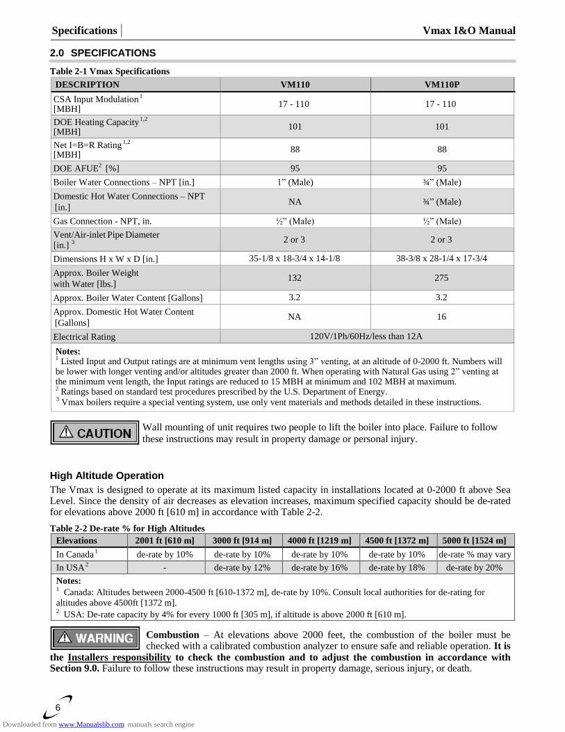
2.0 SPECIFICATIONS
Table 2-1 Vmax Specifications
DESCRIPTION VM110 VM110P
CSA Input Modulation
1
[MBH] 17 - 110 17 - 110
DOE Heating Capacity
1,2
[MBH] 101 101
Net I=B=R Rating
1,2
[MBH] 88 88
DOE AFUE2 [%] 95 95
Boiler Water Connections – NPT [in.] 1” (Male) ¾” (Male)
Domestic Hot Water Connections – NPT
[in.] NA ¾” (Male)
Gas Connection - NPT, in. ½” (Male) ½” (Male)
Vent/Air-inlet Pipe
Diameter
[in.] 3
2 or 3 2 or 3
Dimensions H x W x D [in.] 35-1/8 x 18-3/4 x 14-1/8 38-3/8 x 28-1/4 x 17-3/4
Approx. Boiler Weight
with Water [lbs.] 132 275
Approx. Boiler Water Content [Gallons] 3.2 3.2
Approx. Domestic Hot Water Content
[Gallons] NA 16
Electrical Rating 120V/1Ph/60Hz/less than 12A
Notes: 1 Listed Input and Output ratings are at minimum vent lengths using 3” venting, at an altitude of 0-2000 ft. Numbers will
be lower with longer venting and/or altitudes greater than 2000 ft. When operating with Natural Gas using 2” venting at the minimum vent length, the Input ratings are reduced to 15 MBH at minimum and 102 MBH at maximum. 2 Ratings based on standard test procedures prescribed by the U.S. Department of Energy.
3 Vmax boilers require a special venting system, use only vent materials and methods detailed in these instructions.
Wall mounting of unit requires two people to lift the boiler into place. Failure to follow
these instructions may result in property damage or personal injury.
High Altitude Operation
The Vmax is designed to operate at its maximum listed capacity in installations located at 0-2000 ft above Sea Level. Since the density of air decreases as elevation increases, maximum specified capacity should be de-rated for elevations above 2000 ft [610 m] in accordance with Table 2-2.
Table 2-2 De-rate % for High Altitudes
Elevations 2001 ft [610 m] 3000 ft [914 m] 4000 ft [1219 m] 4500 ft [1372 m] 5000 ft [1524 m]
In Canada
1 de-rate by 10% de-rate by 10% de-rate by 10% de-rate by 10% de-rate % may vary
In USA
2 - de-rate by 12% de-rate by 16% de-rate by 18% de-rate by 20%
Notes: 1
Canada: Altitudes between 2000-4500 ft [610-1372 m], de-rate by 10%. Consult local authorities for de-rating for
altitudes above 4500ft [1372 m]. 2
USA: De-rate capacity by 4% for every 1000 ft [305 m], if altitude is above 2000 ft [610 m].
Combustion – At elevations above 2000 feet, the combustion of the boiler must be checked with a calibrated combustion analyzer to ensure safe and reliable operation. It is
the Installers responsibility to check the combustion and to adjust the combustion in accordance with Section 9.0. Failure to follow these instructions may result in property damage, serious injury, or death.
Downloaded from www.Manualslib.com manuals search engine
Vmax I&O Manual │Boiler Location
7
3.0 BOILER LOCATION
In all cases, the Vmax VM110 & VM110P must be installed indoors in a dry location where the ambient
temperature must be maintained above freezing and below 100F [38C]. All boiler components must be protected from dripping, spraying water, or rain during operation and servicing. Consider the proximity of system piping, gas and electrical supply, condensate disposal drain, and proximity to vent termination when determining the best boiler location.
Water or flood damaged components must be replaced immediately with new factory-
approved components as failure to do so may result in fire, serious injury, or death.
Boiler Area Ventilation Air Openings
If boiler area clearances are less than the recommended clearances specified in Table 3-1, the boiler area must be
ventilated (Exception: if the boiler area/room has a volume of 150 ft3 or greater, ventilation of the boiler room is
not required). Each ventilation air opening must meet the minimum requirements of 1 in2 per 1000 Btu/hr., but
not less than 100 in2. The lower ventilation opening must be located within 6 in. of the floor while the upper
opening must be located 6 in. from the top of the space.
If the "Boiler Area" does not meet the recommended clearances listed in Table 3-1, and if
the boiler area has a volume less than 150 ft3, it is considered a Closet or Alcove. In
US/Canada, PVC vent pipe and fittings shall not be used within the closet or alcove; only approved CPVC,
Polypropylene or Stainless Steel vent pipe and fittings can be used. See Table 4-4 for a list of approved materials.
Under all circumstances, the minimum clearances listed in Table 3-1 must be provided.
Closet Installations
For closet installations it is necessary to provide two ventilation air openings as shown in Figure 3-1, each providing a minimum area equal to 1 in
2 per 1000 Btu/hr., but not less than 100 in
2 and within 6 in. of the top
and bottom of the closet door. See Table 3-1 for minimum clearances.
Alcove Installations
Alcove installations have the same minimum clearances as closet installations, except the front must be completely open to the room at a distance no greater than 18 in. [457 mm] from the front of the boiler and the room is at least three (3) times the size of the alcove. Provided these conditions are met, the boiler requires no extra ventilation air openings to the space. See Table 3-1 for minimum clearances.
Residential Garage Installations
When installed in a residential garage, mount the boiler a minimum of 18 in. [457 mm] above the floor. Locate or protect the boiler so it cannot be damaged by a moving vehicle. Check with your local authorities for other possible regulations pertaining to the installation of a boiler in a garage.
Wall Mounting Installations
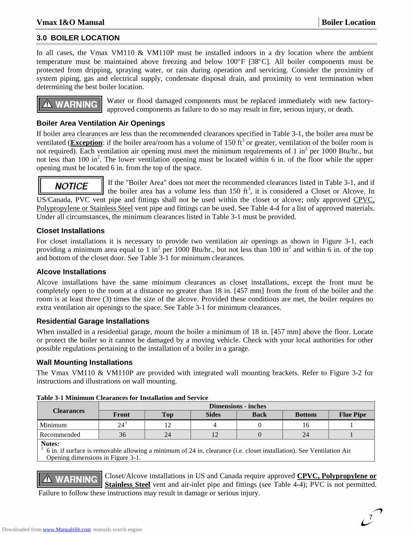
The Vmax VM110 & VM110P are provided with integrated wall mounting brackets. Refer to Figure 3-2 for instructions and illustrations on wall mounting. Table 3-1 Minimum Clearances for Installation and Service
Clearances Dimensions - inches
Front Top Sides Back Bottom Flue Pipe
Minimum 24
1 12 4 0 16 1
Recommended 36 24 12 0 24 1
Notes: 1
6 in. if surface is removable allowing a minimum of 24 in. clearance (i.e. closet installation). See Ventilation Air Opening dimensions in Figure 3-1.
Closet/Alcove installations in US and Canada require approved CPVC, Polypropylene or
Stainless Steel vent and air-inlet pipe and fittings (see Table 4-4); PVC is not permitted.
Failure to follow these instructions may result in damage or serious injury.
Downloaded from www.Manualslib.com manuals search engine
Boiler Location │ Vmax I&O Manual
8
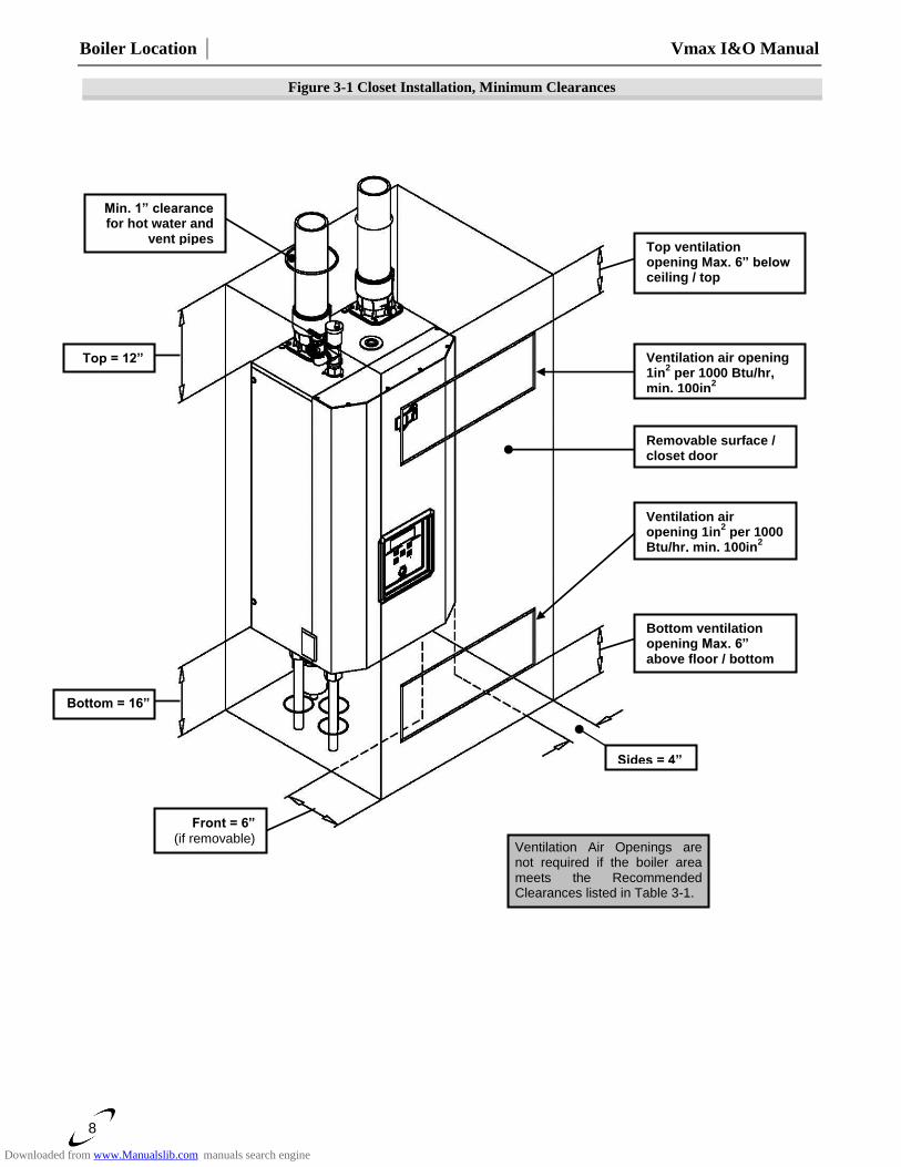
Figure 3-1 Closet Installation, Minimum Clearances
Ventilation Air Openings are not required if the boiler area meets the Recommended
Clearances listed in Table 3-1.
Top ventilation opening Max. 6” below ceiling / top
Ventilation air opening 1in
2 per 1000 Btu/hr,
min. 100in2
Removable surface / closet door
Ventilation air opening 1in
2 per 1000
Btu/hr, min. 100in2
Bottom ventilation opening Max. 6” above floor / bottom
Sides = 4”
Top = 12”
Bottom = 16”
Min. 1” clearance for hot water and
vent pipes
Front = 6”
(if removable)
Downloaded from www.Manualslib.com manuals search engine
Vmax I&O Manual │Boiler Location
9
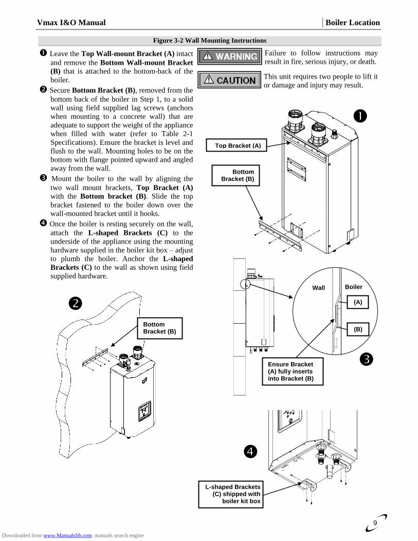
Figure 3-2 Wall Mounting Instructions
Leave the Top Wall-mount Bracket (A) intact
and remove the Bottom Wall-mount Bracket
(B) that is attached to the bottom-back of the
boiler.
Secure Bottom Bracket (B), removed from the
bottom back of the boiler in Step 1, to a solid
wall using field supplied lag screws (anchors
when mounting to a concrete wall) that are
adequate to support the weight of the appliance
when filled with water (refer to Table 2-1
Specifications). Ensure the bracket is level and
flush to the wall. Mounting holes to be on the
bottom with flange pointed upward and angled
away from the wall.
Mount the boiler to the wall by aligning the
two wall mount brackets, Top Bracket (A)
with the Bottom bracket (B). Slide the top
bracket fastened to the boiler down over the
wall-mounted bracket until it hooks.
Once the boiler is resting securely on the wall,
attach the L-shaped Brackets (C) to the
underside of the appliance using the mounting
hardware supplied in the boiler kit box – adjust
to plumb the boiler. Anchor the L-shaped
Brackets (C) to the wall as shown using field
supplied hardware.
Failure to follow instructions may
result in fire, serious injury, or death.
This unit requires two people to lift it
or damage and injury may result.
Bottom Bracket (B)
Wall Boiler
Ensure Bracket (A) fully inserts into Bracket (B)
(B)
(A)
L-shaped Brackets (C) shipped with
boiler kit box
Top Bracket (A)
Bottom Bracket (B)
Downloaded from www.Manualslib.com manuals search engine
General Venting │ Vmax I&O Manual
10
4.0 GENERAL VENTING
The Vmax VM110 & VM110P are certified as a “Category IV” boiler requiring a “Special Venting System”
designed for pressurized venting. The Exhaust Vent must be piped to the outdoors, using the vent materials and
rules outlined in this section. Under no conditions may this unit vent gases into a masonry chimney, unless it is
vacant, and utilizes the approved venting material and rules described in this section.
Vent and Air-inlet are to be piped separately. The Vmax VM110 & VM110P cannot share
a common vent or air-inlet with multiple boilers. Failure to comply will result in serious
injury or death.
Direct Vent Installation (Best Practice)
When installed as a Direct Vent boiler the combustion air-inlet must also be piped directly to the outdoors using
the methods described in this section and in accordance with the National Fuel Gas Code, ANSI Z223.1 (U.S.) or
CSA B149.1 (Canada) and local requirements.
Installation Using Indoor Combustion Air
When the installation uses Indoor Combustion Air (i.e. piping is not directly connecting the appliance air-inlet
fitting to the outdoors), provisions for combustion and ventilation air, in accordance with section “Air for
Combustion and Ventilation,” of the National Fuel Gas Code, ANSI Z223.1/NFPA 54 (U.S.), or Clause 8.2, 8.3
or 8.4 of Natural Gas and Propane Installation Code, CAN/CSA B149.1 (Canada), or applicable provisions of
the local building codes, must be adhered to.
The boiler shall be located so as not to interfere with proper circulation of combustion,
ventilation, and dilution air.
Make up air requirements for the operation of exhaust fans, kitchen ventilation systems,
clothes dryers, and fireplaces shall be considered in determining the adequacy of a space
to provide combustion air requirements. Failure to ensure adequate make up air to all
appliances may result in personal injury or death.
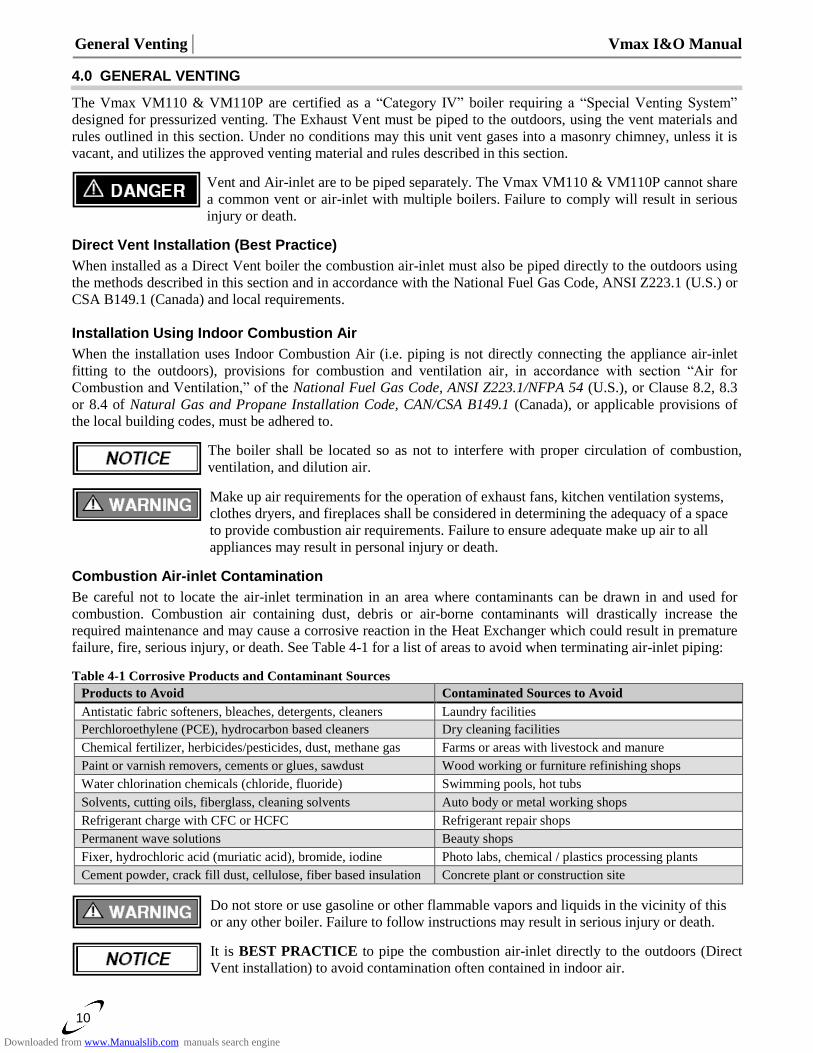
Combustion Air-inlet Contamination
Be careful not to locate the air-inlet termination in an area where contaminants can be drawn in and used for
combustion. Combustion air containing dust, debris or air-borne contaminants will drastically increase the
required maintenance and may cause a corrosive reaction in the Heat Exchanger which could result in premature
failure, fire, serious injury, or death. See Table 4-1 for a list of areas to avoid when terminating air-inlet piping:
Table 4-1 Corrosive Products and Contaminant Sources Products to Avoid Contaminated Sources to Avoid
Antistatic fabric softeners, bleaches, detergents, cleaners Laundry facilities
Perchloroethylene (PCE), hydrocarbon based cleaners Dry cleaning facilities
Chemical fertilizer, herbicides/pesticides, dust, methane gas Farms or areas with livestock and manure
Paint or varnish removers, cements or glues, sawdust Wood working or furniture refinishing shops
Water chlorination chemicals (chloride, fluoride) Swimming pools, hot tubs
Solvents, cutting oils, fiberglass, cleaning solvents Auto body or metal working shops
Refrigerant charge with CFC or HCFC Refrigerant repair shops
Permanent wave solutions Beauty shops
Fixer, hydrochloric acid (muriatic acid), bromide, iodine Photo labs, chemical / plastics processing plants
Cement powder, crack fill dust, cellulose, fiber based insulation Concrete plant or construction site
Do not store or use gasoline or other flammable vapors and liquids in the vicinity of this
or any other boiler. Failure to follow instructions may result in serious injury or death.
It is BEST PRACTICE to pipe the combustion air-inlet directly to the outdoors (Direct
Vent installation) to avoid contamination often contained in indoor air.
Downloaded from www.Manualslib.com manuals search engine
Vmax I&O Manual │General Venting
11
Flammable Solvents and Plastic Piping
Due to the extremely flammable characteristics of most glues, cements, solvents and primers used in the process
of joining plastic vent and air-inlet pipe, explosive solvent vapors must be evacuated from the vent and air-inlet
prior to start-up. Avoid using excess cement or primer that may lead to pooling inside the pipe assembly. Freshly
assembled piping assembly should be allowed to cure for a minimum of 8 hours before applying power to the gas
fired boiler. Refer to Mandatory Pre-commissioning Procedure for Plastic Venting in this section.
Flammable Cements and Primers – It is the installers’ responsibility to familiarize
themselves with the hazards associated with explosive solvents and to take all precautions
to reduce these risks. Failure to follow these instructions can cause explosions, property damage, injury or death.
Mandatory Pre-commissioning Procedure for Plastic Venting (PVC or CPVC)
Do not apply power to the boiler prior to Step 4 in the Mandatory Pre-commissioning
Procedure for Plastic Venting.
1) Working with the power turned off to the boiler, completely install the vent and air intake system, securely cementing joints together. If possible, allow primers/cements to cure for 8 hours before firing the burner. If curing time is less than 8 hours, proceed with Steps 2 through 6.
2) Maintain the boiler gas supply shut-off valve in the off position. 3) Remove the cable from the Spark Ignition Electrode and Ignition Controller.
Spark Ignition Circuit - Maintain a safe distance (2 in. minimum) from the spark ignition
circuit to avoid injury from electrical shock.
4) Turn power on to the boiler and apply a heat demand. 5) Allow for 5 complete trials for ignition, consisting of pre and post purge of the combustion blower, until an
ignition lockout occurs. Repeat the process one more time (i.e. 10 complete ignition sequences in total). 6) Turn power off and reconnect the cable to the Spark Ignition Transformer.
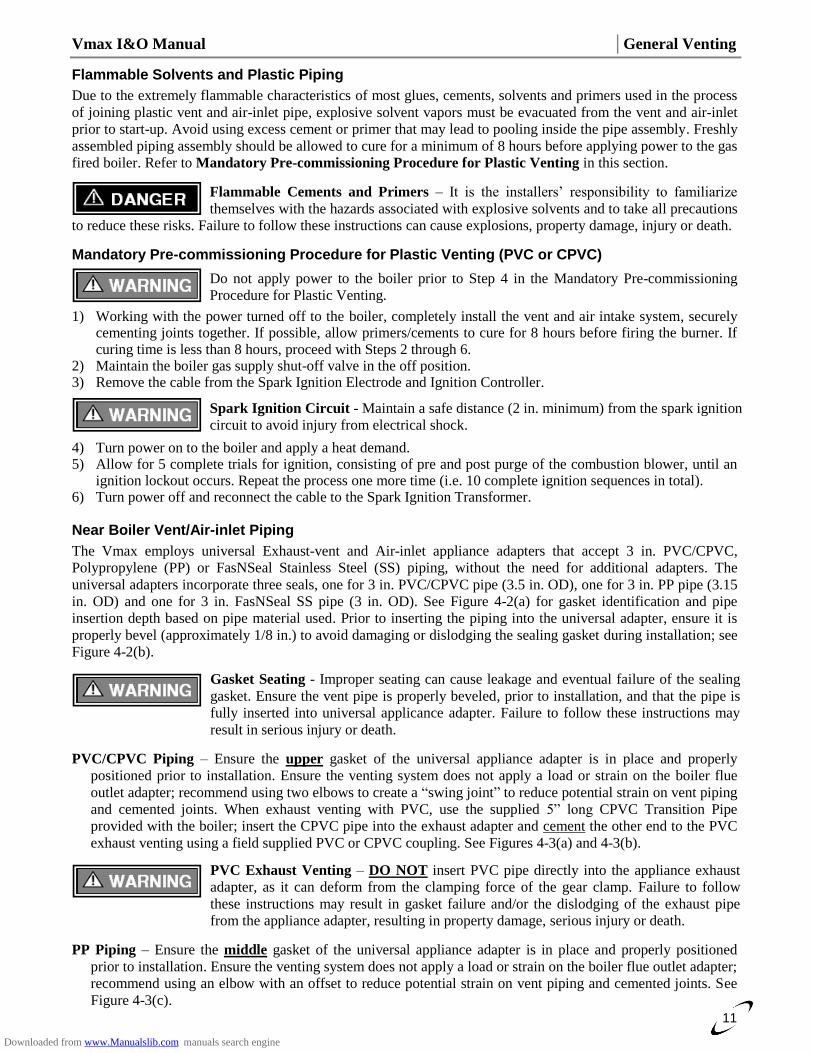
Near Boiler Vent/Air-inlet Piping
The Vmax employs universal Exhaust-vent and Air-inlet appliance adapters that accept 3 in. PVC/CPVC,
Polypropylene (PP) or FasNSeal Stainless Steel (SS) piping, without the need for additional adapters. The
universal adapters incorporate three seals, one for 3 in. PVC/CPVC pipe (3.5 in. OD), one for 3 in. PP pipe (3.15
in. OD) and one for 3 in. FasNSeal SS pipe (3 in. OD). See Figure 4-2(a) for gasket identification and pipe
insertion depth based on pipe material used. Prior to inserting the piping into the universal adapter, ensure it is
properly bevel (approximately 1/8 in.) to avoid damaging or dislodging the sealing gasket during installation; see
Figure 4-2(b).
Gasket Seating - Improper seating can cause leakage and eventual failure of the sealing
gasket. Ensure the vent pipe is properly beveled, prior to installation, and that the pipe is
fully inserted into universal applicance adapter. Failure to follow these instructions may
result in serious injury or death.
PVC/CPVC Piping – Ensure the upper gasket of the universal appliance adapter is in place and properly
positioned prior to installation. Ensure the venting system does not apply a load or strain on the boiler flue
outlet adapter; recommend using two elbows to create a “swing joint” to reduce potential strain on vent piping
and cemented joints. When exhaust venting with PVC, use the supplied 5” long CPVC Transition Pipe
provided with the boiler; insert the CPVC pipe into the exhaust adapter and cement the other end to the PVC
exhaust venting using a field supplied PVC or CPVC coupling. See Figures 4-3(a) and 4-3(b).
PVC Exhaust Venting – DO NOT insert PVC pipe directly into the appliance exhaust
adapter, as it can deform from the clamping force of the gear clamp. Failure to follow
these instructions may result in gasket failure and/or the dislodging of the exhaust pipe
from the appliance adapter, resulting in property damage, serious injury or death.
PP Piping – Ensure the middle gasket of the universal appliance adapter is in place and properly positioned
prior to installation. Ensure the venting system does not apply a load or strain on the boiler flue outlet adapter;
recommend using an elbow with an offset to reduce potential strain on vent piping and cemented joints. See
Figure 4-3(c).
Downloaded from www.Manualslib.com manuals search engine
General Venting │ Vmax I&O Manual
12
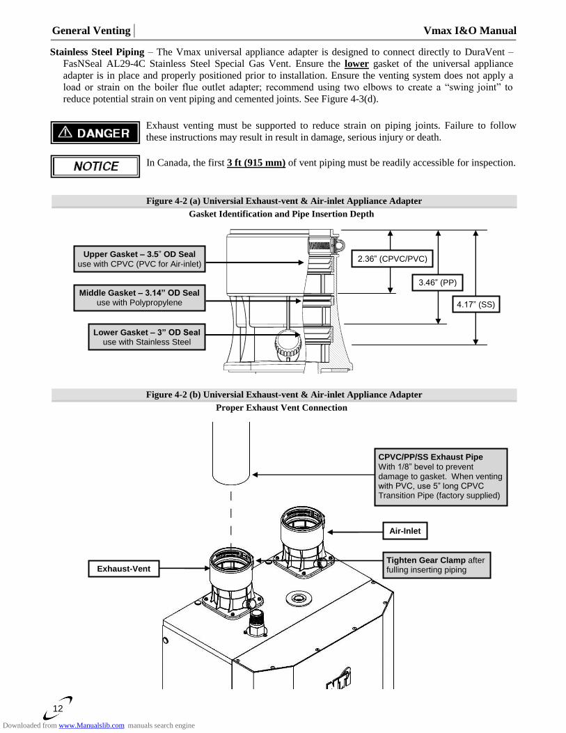
Stainless Steel Piping – The Vmax universal appliance adapter is designed to connect directly to DuraVent –
FasNSeal AL29-4C Stainless Steel Special Gas Vent. Ensure the lower gasket of the universal appliance
adapter is in place and properly positioned prior to installation. Ensure the venting system does not apply a
load or strain on the boiler flue outlet adapter; recommend using two elbows to create a “swing joint” to
reduce potential strain on vent piping and cemented joints. See Figure 4-3(d).
Exhaust venting must be supported to reduce strain on piping joints. Failure to follow
these instructions may result in result in damage, serious injury or death.
In Canada, the first 3 ft (915 mm) of vent piping must be readily accessible for inspection.
Figure 4-2 (a) Universial Exhaust-vent & Air-inlet Appliance Adapter
Gasket Identification and Pipe Insertion Depth
Figure 4-2 (b) Universial Exhaust-vent & Air-inlet Appliance Adapter
Proper Exhaust Vent Connection
Lower Gasket – 3” OD Seal use with Stainless Steel
Middle Gasket – 3.14” OD Seal use with Polypropylene
Upper Gasket – 3.5” OD Seal
use with CPVC (PVC for Air-inlet) 2.36” (CPVC/PVC)
3.46” (PP)
4.17” (SS)
CPVC/PP/SS Exhaust Pipe
With 1/8” bevel to prevent damage to gasket. When venting with PVC, use 5” long CPVC Transition Pipe (factory supplied)
Exhaust-Vent
Air-Inlet
Tighten Gear Clamp after fulling inserting piping
Downloaded from www.Manualslib.com manuals search engine
Vmax I&O Manual │General Venting
13
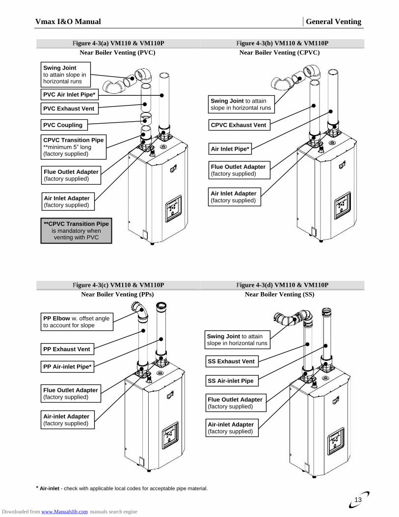
Figure 4-3(a) VM110 & VM110P Figure 4-3(b) VM110 & VM110P
Near Boiler Venting (PVC) Near Boiler Venting (CPVC)
Figure 4-3(c) VM110 & VM110P Figure 4-3(d) VM110 & VM110P
Near Boiler Venting (PPs)
Near Boiler Venting (SS)
Air-inlet - check with applicable local codes for acceptable pipe material.
PP Elbow w. offset angle
to account for slope
PP Exhaust Vent
Flue Outlet Adapter (factory supplied)
Air-inlet Adapter
(factory supplied)
PP Air-inlet Pipe*
Swing Joint to attain slope in horizontal runs
SS Exhaust Vent
Flue Outlet Adapter (factory supplied)
Air-inlet Adapter (factory supplied)
SS Air-inlet Pipe
Air Inlet Pipe*
Swing Joint to attain
slope in horizontal runs
CPVC Exhaust Vent
Air Inlet Adapter
(factory supplied)
Flue Outlet Adapter (factory supplied)
Swing Joint
to attain slope in horizontal runs
CPVC Transition Pipe
**minimum 5” long (factory supplied)
Flue Outlet Adapter (factory supplied)
**CPVC Transition Pipe
is mandatory when venting with PVC
PVC Coupling
Air Inlet Adapter (factory supplied)
PVC Air Inlet Pipe*
PVC Exhaust Vent
Downloaded from www.Manualslib.com manuals search engine
General Venting │ Vmax I&O Manual
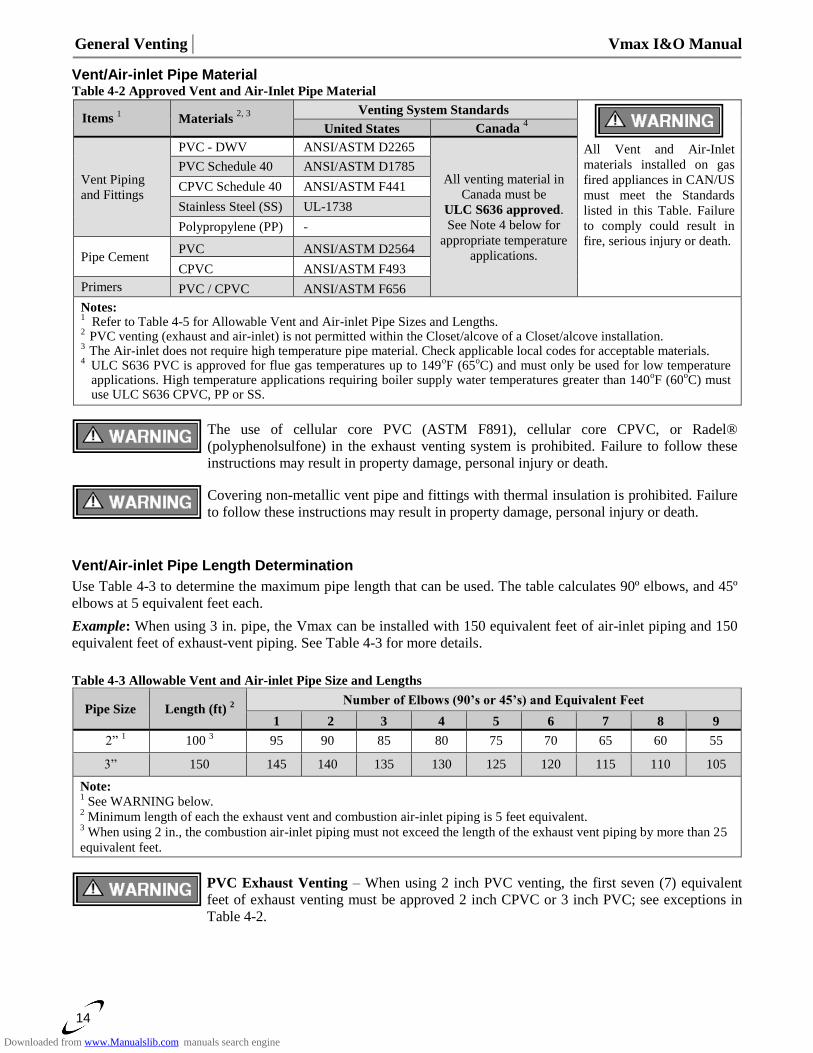
14
Vent/Air-inlet Pipe Material Table 4-2 Approved Vent and Air-Inlet Pipe Material
Items 1 Materials
2, 3
Venting System Standards
All Vent and Air-Inlet
materials installed on gas
fired appliances in CAN/US
must meet the Standards
listed in this Table. Failure
to comply could result in
fire, serious injury or death.
United States Canada 4
Vent Piping
and Fittings
PVC - DWV ANSI/ASTM D2265
All venting material in
Canada must be
ULC S636 approved.
See Note 4 below for
appropriate temperature
applications.
PVC Schedule 40 ANSI/ASTM D1785
CPVC Schedule 40 ANSI/ASTM F441
Stainless Steel (SS) UL-1738
Polypropylene (PP) -
Pipe Cement PVC ANSI/ASTM D2564
CPVC ANSI/ASTM F493
Primers PVC / CPVC ANSI/ASTM F656
Notes: 1
Refer to Table 4-5 for Allowable Vent and Air-inlet Pipe Sizes and Lengths. 2
PVC venting (exhaust and air-inlet) is not permitted within the Closet/alcove of a Closet/alcove installation. 3
The Air-inlet does not require high temperature pipe material. Check applicable local codes for acceptable materials. 4
ULC S636 PVC is approved for flue gas temperatures up to 149oF (65
oC) and must only be used for low temperature
applications. High temperature applications requiring boiler supply water temperatures greater than 140oF (60
oC) must
use ULC S636 CPVC, PP or SS.
The use of cellular core PVC (ASTM F891), cellular core CPVC, or Radel®
(polyphenolsulfone) in the exhaust venting system is prohibited. Failure to follow these
instructions may result in property damage, personal injury or death.
Covering non-metallic vent pipe and fittings with thermal insulation is prohibited. Failure
to follow these instructions may result in property damage, personal injury or death.
Vent/Air-inlet Pipe Length Determination
Use Table 4-3 to determine the maximum pipe length that can be used. The table calculates 90º elbows, and 45º
elbows at 5 equivalent feet each.
Example: When using 3 in. pipe, the Vmax can be installed with 150 equivalent feet of air-inlet piping and 150
equivalent feet of exhaust-vent piping. See Table 4-3 for more details.
Table 4-3 Allowable Vent and Air-inlet Pipe Size and Lengths
Pipe Size Length (ft) 2
Number of Elbows (90’s or 45’s) and Equivalent Feet
1 2 3 4 5 6 7 8 9
2” 1
100 3 95 90 85 80 75 70 65 60 55
3” 150 145 140 135 130 125 120 115 110 105
Note: 1 See WARNING below.
2 Minimum length of each the exhaust vent and combustion air-inlet piping is 5 feet equivalent.
3 When using 2 in., the combustion air-inlet piping must not exceed the length of the exhaust vent piping by more than 25
equivalent feet.
PVC Exhaust Venting – When using 2 inch PVC venting, the first seven (7) equivalent
feet of exhaust venting must be approved 2 inch CPVC or 3 inch PVC; see exceptions in
Table 4-2.
Downloaded from www.Manualslib.com manuals search engine
Vmax I&O Manual │General Venting
15
Termination Options – Direct Vent Installation
The venting system of the VM110 and VM110P may be terminated using field supplied piping to construct a
“Two-Pipe” termination, see Figures 4-4(a), 4-5(a), 4-5(d), 4-6(a), 4-7(a) and 4-7(d); alternatively the venting
may be terminated using a factory kit selected from Table 4-4.
Venting Options - Due to potential moisture loading (build-up) along the exterior wall,
sidewall venting may not be the preferred venting option (see Figures 4-5 and 4-7).
The vent for this appliance shall not terminate over public walkways; or near soffit vents
or crawl space vents or other area where condensate of vapor could create a nuisance or
hazard or cause property damage; or where condensate or vapor could cause damage or
could be detrimental to the operation of regulators, relief valves, or other equipment.
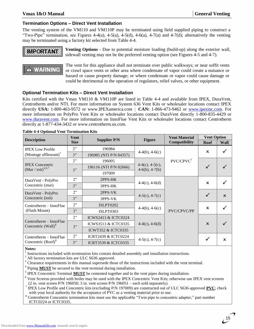
Optional Termination Kits – Direct Vent Installation
Kits certified with the Vmax VM110 & VM110P are listed in Table 4-4 and available from IPEX, DuraVent, Centrotherm and/or NTI. For more information on System 636 Vent Kits or wholesaler locations contact IPEX directly USA: 1-800-463-9572 or www.IPEXamerica.com │ CAN: 1-866-473-9462 or www.ipexinc.com. For more information on PolyPro Vent Kits or wholesaler locations contact DuraVent directly 1-800-835-4429 or www.duravent.com. For more information on InnoFlue Vent Kits or wholesaler locations contact Centrotherm directly at 1-877-434-3432 or www.centrotherm.us.com.
Table 4-4 Optional Vent Termination Kits
Description Vent Size
Supplier P/N Figure Vent Material Compatibility
Vent Option
Roof Wall
IPEX Low Profile
(Montage affleurant)7
2” 196984 4-4(b), 4-6(c)
PVC/CPVC7
3” 196985 (NTI P/N 84357)
IPEX Concentric
(Mur / toit)5,6,7
2” 196005 4-4(c), 4-5(c),
4-6(b), 4-7(b) 3”
196116 (NTI P/N 82666)
197009
DuraVent - PolyPro
Concentric (mur)
2” 2PPS-HK 4-4(c), 4-6(d)
PVC/CPVC/PP
3” 3PPS-HK
DuraVent - PolyPro
Concentric (toit)
2” 2PPS-VK 4-5(c), 4-7(c)
3” 3PPS-VK
Centrotherm – InnoFlue
(Flush Mount)
2” ISLPT0202 4-4(b), 4-6(c)
3” ISLPT0303
Centrotherm – InnoFlue
Concentric (Wall)8
2” ICWS2413 & ICTC0224
4-4(c), 4-6(d) 3”
ICWS3513 & ICTC0335
ICWT352 & ICTC0335
Centrotherm – InnoFlue
Concentric (Roof)8
2” ICRT2439 & ICTC0224 4-5(c), 4-7(c)
3” ICRT3539 & ICTC0335
Notes: 1 Instructions included with termination kits contain detailed assembly and installation instructions.
2 All factory termination kits are ULC S636 approved.
3 Clearance requirements in this manual supersede those of the instructions included with the vent terminal.
4 Piping MUST be secured to the vent terminal during installation.
5 IPEX Concentric Terminal MUST be cemented together and to the vent pipes during installation.
6 Vent Screens provided with boiler may be used with the IPEX Concentric Vent Kits; otherwise use IPEX vent screens
(2 in. vent screen P/N 196050; 3 in. vent screen P/N 196051 – each sold separately). 7 IPEX Low Profile and Concentric kits (excluding P/N 197009) are constructed out of ULC S636 approved PVC; check
with your local authority for the acceptance of PVC as a venting material prior to use. 8 Centrotherm Concentric termination kits must use the applicable “Twin pipe to concentric adapter,” part number
ICTC0224 or ICTC0335.
Downloaded from www.Manualslib.com manuals search engine
General Venting │ Vmax I&O Manual
16
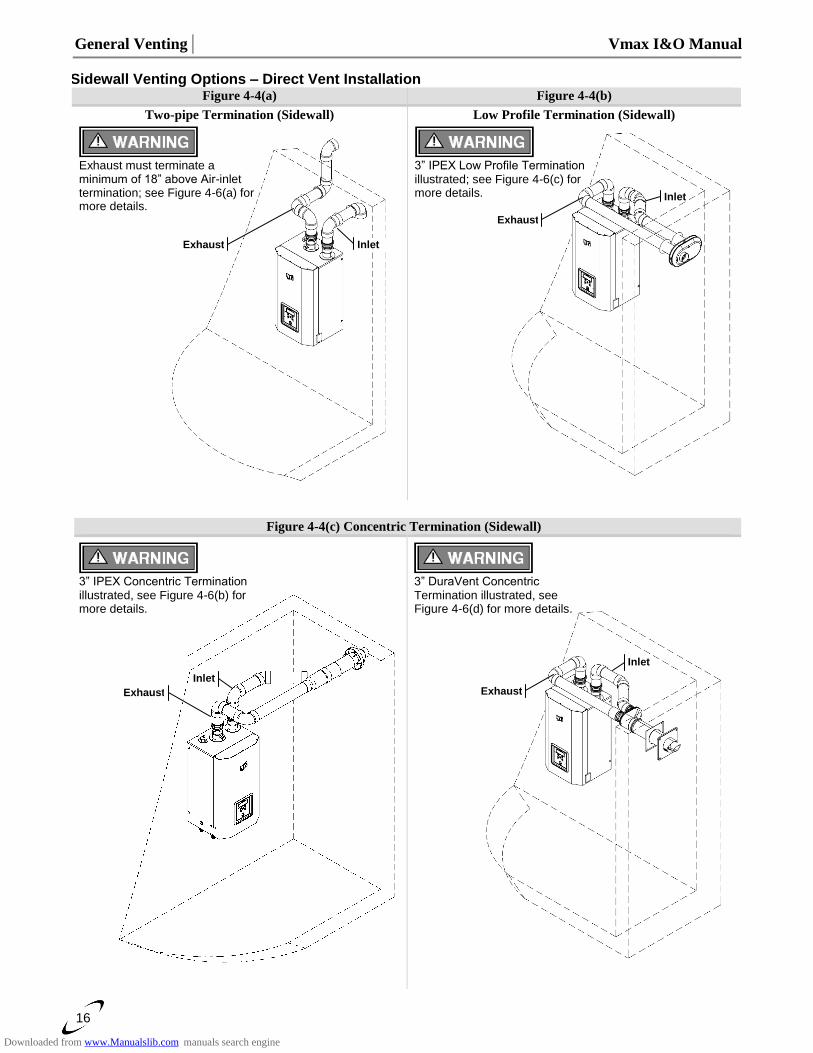
Sidewall Venting Options – Direct Vent Installation
Figure 4-4(a) Figure 4-4(b)
Two-pipe Termination (Sidewall) Low Profile Termination (Sidewall)
Figure 4-4(c) Concentric Termination (Sidewall)
Exhaust must terminate a minimum of 18” above Air-inlet termination; see Figure 4-6(a) for more details.
Exhaust Inlet
3” IPEX Low Profile Termination illustrated; see Figure 4-6(c) for more details.
Exhaust
Inlet
3” DuraVent Concentric Termination illustrated, see Figure 4-6(d) for more details.
Exhaust
Inlet
3” IPEX Concentric Termination illustrated, see Figure 4-6(b) for more details.
Exhaust
Inlet
Downloaded from www.Manualslib.com manuals search engine
Vmax I&O Manual │General Venting
17
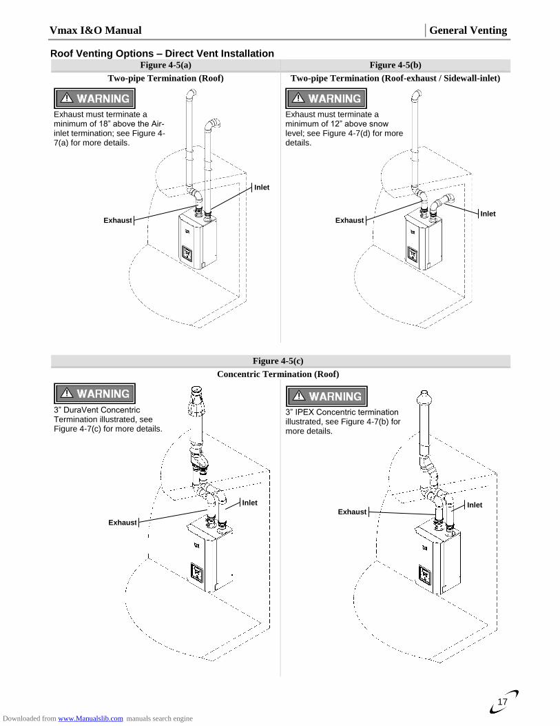
Roof Venting Options – Direct Vent Installation
Figure 4-5(a) Figure 4-5(b)
Two-pipe Termination (Roof) Two-pipe Termination (Roof-exhaust / Sidewall-inlet)
Figure 4-5(c)
Concentric Termination (Roof)
3” DuraVent Concentric Termination illustrated, see Figure 4-7(c) for more details.
Exhaust
Inlet
Exhaust
Inlet
Exhaust must terminate a minimum of 18” above the Air-inlet termination; see Figure 4-7(a) for more details.
3” IPEX Concentric termination illustrated, see Figure 4-7(b) for more details.
Exhaust Inlet
Exhaust Inlet
Exhaust must terminate a minimum of 12” above snow level; see Figure 4-7(d) for more details.
Downloaded from www.Manualslib.com manuals search engine
General Venting │ Vmax I&O Manual
18
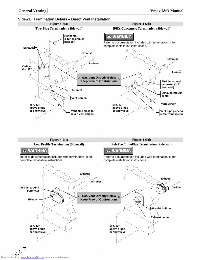
Sidewall Termination Details – Direct Vent Installation Figure 4-6(a) Figure 4-6(b)
Two-Pipe Termination (Sidewall) IPEX Concentric Termination (Sidewall)
Refer to documentation included with termination kit for complete installation instructions.
Figure 4-6(c) Figure 4-6(d)
Low Profile Termination (Sidewall) PolyPro / InnoFlue Termination (Sidewall)
Refer to documentation included with termination kit for complete installation instructions.
Min. 12” above grade or snow level
Exhaust
Air-inlet
Exhaust
Air-inlet around perimeter
Min. 12” above grade or snow level
Exhaust center
Air-inlet bottom
Exhaust
Air-inlet
Gas Vent Directly Below
Keep Free of Obstructions
Refer to documentation included with termination kit for complete installation instructions.
Exhaust
Air-inlet
Min. 12” above grade or snow level
Vertical Min. 18”
Horizontal 4-12” or greater than 36”
Exhaust
Air-inlet
Vent Screen
Vent pipe piece to retain vent screen
Gas Vent Directly Below
Keep Free of Obstructions
Exhaust
Air-inlet
Min. 12” above grade or snow level
Air-inlet around perimeter (1-2” from wall)
Exhaust through center
Vent Screen
Vent pipe piece to retain vent screen
Downloaded from www.Manualslib.com manuals search engine
Vmax I&O Manual │General Venting
19
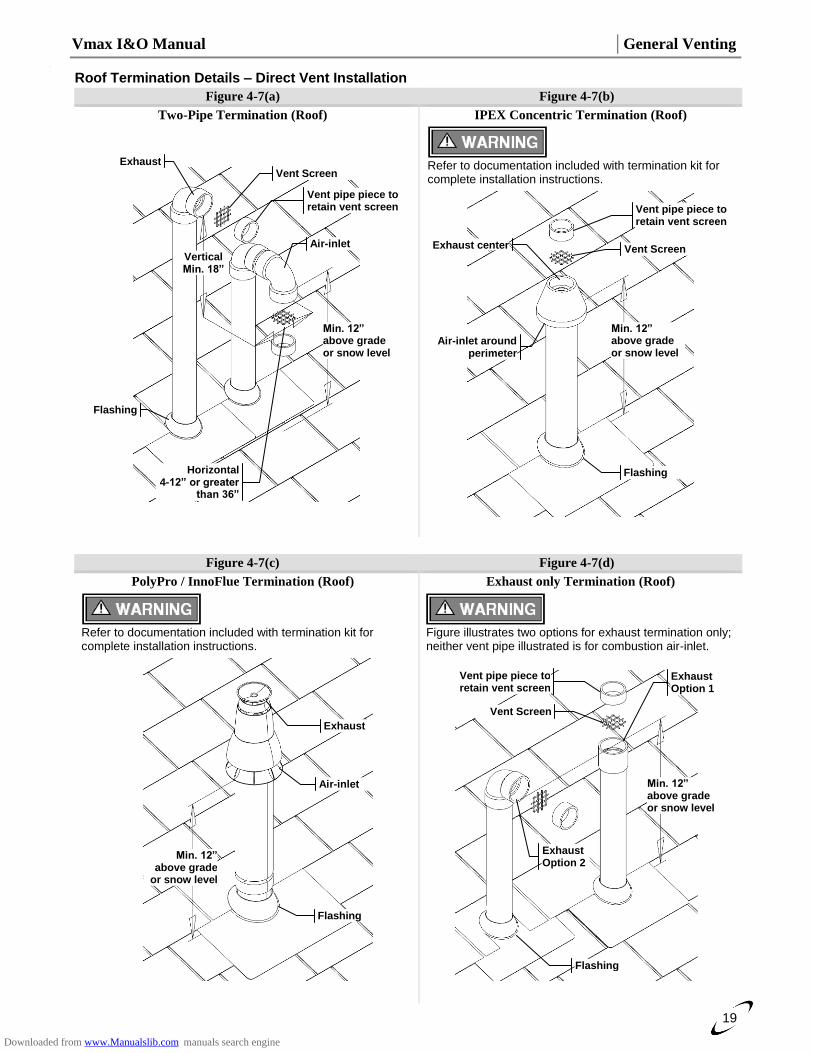
Roof Termination Details – Direct Vent Installation
Figure 4-7(a) Figure 4-7(b)
Two-Pipe Termination (Roof) IPEX Concentric Termination (Roof)
Figure 4-7(c) Figure 4-7(d)
PolyPro / InnoFlue Termination (Roof) Exhaust only Termination (Roof)
Min. 12” above grade or snow level
Vent Screen
Vent pipe piece to retain vent screen
Exhaust
Air-inlet
Vertical Min. 18”
Horizontal 4-12” or greater
than 36”
Flashing
Min. 12” above grade or snow level
Vent Screen
Vent pipe piece to retain vent screen
Exhaust center
Air-inlet around perimeter
Flashing
Refer to documentation included with termination kit for complete installation instructions.
Refer to documentation included with termination kit for complete installation instructions.
Min. 12” above grade
or snow level
Flashing
Exhaust
Air-inlet
Figure illustrates two options for exhaust termination only; neither vent pipe illustrated is for combustion air-inlet.
Min. 12” above grade or snow level
Flashing
Vent pipe piece to retain vent screen
Vent Screen
Exhaust Option 1
Exhaust Option 2
Downloaded from www.Manualslib.com manuals search engine
General Venting │ Vmax I&O Manual
20
Venting Rules and Guidelines
1. Prevailing Winds: Ensure the vent is located where it will not be exposed to normal prevailing winds.
2. Combustion Air-inlet Contamination: Air for combustion must be drawn from an area free of dust and contaminants. Combustion air containing chemicals such as chloride, fluoride, bromine or iodine or dust and debris will cause corrosion damage of the heat exchanger voiding your NTI warranty. Refer to Table 4-1 for a list of corrosive products and contaminants sources to avoid.
3. Vertical Separation: The exhaust must be a minimum of 18 in. above the air inlet, and the air inlet must always be a minimum of 12 in. plus snow allowance above any surface that will support snow. (Two feet plus snow allowance is highly recommended). Consult your weather office for the maximum typical snowfall for your region.
Example: New Brunswick Canada - typical maximum snowfall is 19 in., thus the inlet must be (12”+19”) = 31 in. above grade and exhaust must be (31”+18”) = 49” above grade.
4. Horizontal Separation: The horizontal distance between the inlet and exhaust must be a minimum of 4” [102 mm] center to center.
5. Wall Flashing: Under normal operating conditions this boiler will produce a plume of white gases, and should be taken into consideration when selecting an adequate location. A 36 in. diameter stainless, plastic, or vinyl shield can be used to flash the exterior of the residence.
6. Flue Gas Hazard: Position the vent termination where vapors cannot make accidental contact with people and pets or damage nearby shrubs and plants.
7. Elbow Extensions: Elbows on outside of wall must be no more than ½ in. away from the wall.
8. Vent Sloping: All indoor exhaust piping must be on a slope back to the boiler a minimum of ¼ in. per linear foot of vent. For applications where excessive condensation is possible ½ in. per linear foot is recommended.
9. Vent Supports: Where required Vent and Air-inlet piping shall be secured to the wall for more rigidity. All interior vent pipe shall be supported a minimum of every 36 in..
10. Roof Exhaust: In all roof applications the discharge must point away from the pitch of the roof.
11. Roof Flashing: Install adequate flashing where the pipe enters the roof, to prevent water leakage.
12. Rain Cap: Install and seal a rain cap over existing chimney openings, in vacant chimney applications.
13. Venting Below Grade: For installations that exit the wall below grade refer to Figure 4-8.
14. Vent Screens: Install factory supplied vent screens on the outside of the last elbow for both the inlet and exhaust vent terminal elbows. Install the screen into the female opening of the elbow, and then cut a small piece of pipe to sandwich the screen into the elbow. NOTE: ensure the small piece of pipe cut, does not extend past the end of the elbow. Two screens are provided in the package. See Figures 4-6 and 4-7.
15. Condensate Hazard: Do not locate vent over public walkways, driveways or parking lots. Condensate could drip and freeze resulting in a slip hazard or damage to vehicles and machinery.
16. Warning Plate: For Sidewall Venting, install the warning plate “Gas Vent Directly Below”, directly above (within 4 ft. vertically) the location of the air-inlet pipe, so it is visible from at least 8 ft away. See Figure 4-6.
17. Wall Thickness: Direct vent terminations are designed to work with any standard wall thickness. Installation guidelines for min/max wall thickness are as follows: Min. = 1 in., Max. = 60 in..
18. Venting Options: Due to potential moisture loading (build-up) along the exterior wall, sidewall venting may not be the preferred venting option. Refer to Figures 4-5 and 4-7 for roof top venting options.
Downloaded from www.Manualslib.com manuals search engine
Vmax I&O Manual │General Venting
21
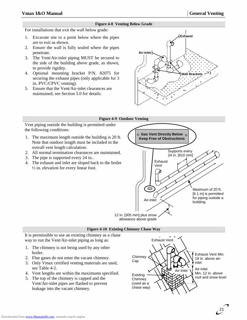
Figure 4-8 Venting Below Grade
For installations that exit the wall below grade:
1. Excavate site to a point below where the pipes
are to exit as shown.
2. Ensure the wall is fully sealed where the pipes
penetrate.
3. The Vent/Air-inlet piping MUST be secured to
the side of the building above grade, as shown,
to provide rigidity.
4. Optional mounting bracket P/N. 82075 for
securing the exhaust pipes (only applicable for 3
in. PVC/CPVC venting).
5. Ensure that the Vent/Air-inlet clearances are
maintained, see Section 5.0 for details.
Figure 4-9 Outdoor Venting
Vent piping outside the building is permitted under
the following conditions:
1. The maximum length outside the building is 20 ft.
Note that outdoor length must be included in the
overall vent length calculation.
2. All normal termination clearances are maintained.
3. The pipe is supported every 24 in..
4. The exhaust and inlet are sloped back to the boiler
½ in. elevation for every linear foot.
Figure 4-10 Existing Chimney Chase Way
It is permissible to use an existing chimney as a chase
way to run the Vent/Air-inlet piping as long as:
1. The chimney is not being used by any other
boiler.
2. Flue gases do not enter the vacant chimney.
3. Only Vmax certified venting materials are used,
see Table 4-2.
4. Vent lengths are within the maximums specified.
5. The top of the chimney is capped and the
Vent/Air-inlet pipes are flashed to prevent
leakage into the vacant chimney.
Exhaust
Air-inlet
Wall Brackets
Supports every 24 in. [610 mm]
12 in. [305 mm] plus snow allowance above grade
Air-Inlet
Maximum of 20 ft. [6.1 m] is permitted for piping outside a building.
Exhaust Vent
Gas Vent Directly Below
Keep Free of Obstructions
Air-Inlet
Existing Chimney (used as a chase way)
Chimney Cap
Exhaust Vent
Exhaust Vent Min. 18 in. above air-inlet
Air-Inlet Min. 12 in. above roof and snow level
Downloaded from www.Manualslib.com manuals search engine
Termination Clearances │ Vmax I&O Manual
22
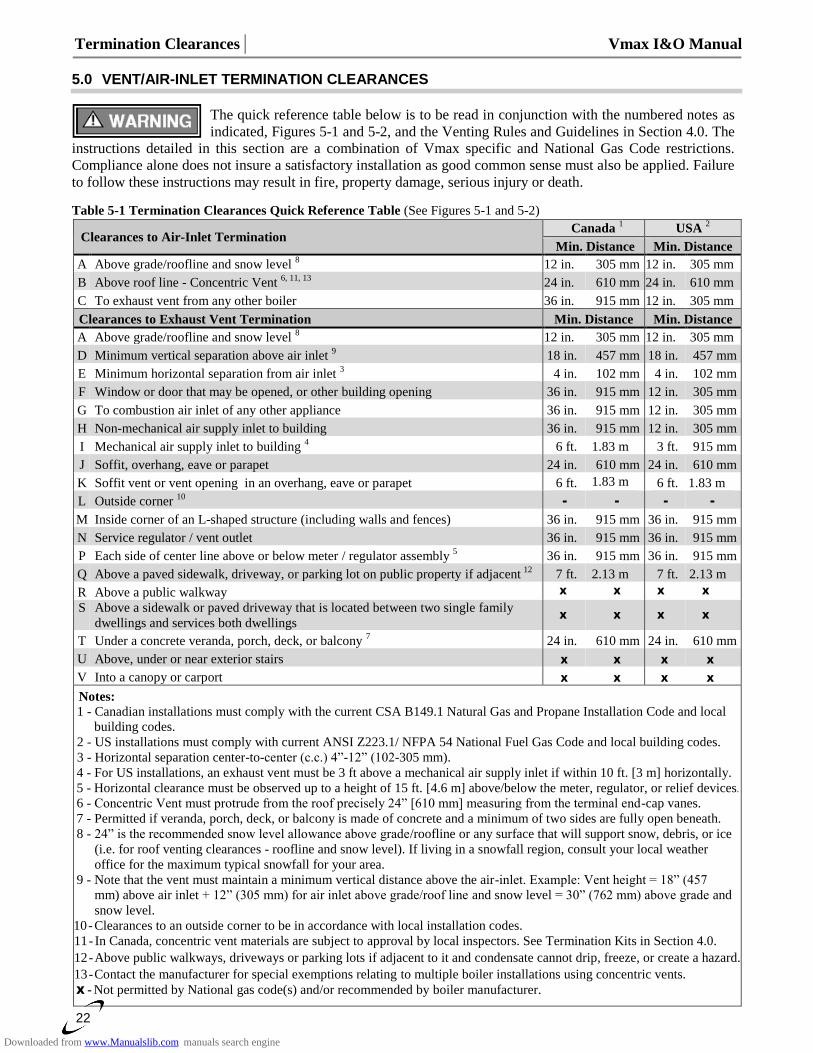
5.0 VENT/AIR-INLET TERMINATION CLEARANCES
The quick reference table below is to be read in conjunction with the numbered notes as
indicated, Figures 5-1 and 5-2, and the Venting Rules and Guidelines in Section 4.0. The
instructions detailed in this section are a combination of Vmax specific and National Gas Code restrictions.
Compliance alone does not insure a satisfactory installation as good common sense must also be applied. Failure
to follow these instructions may result in fire, property damage, serious injury or death.
Table 5-1 Termination Clearances Quick Reference Table (See Figures 5-1 and 5-2)
Clearances to Air-Inlet Termination Canada
1 USA
2
Min. Distance Min. Distance
A Above grade/roofline and snow level 8 12 in. 305 mm 12 in. 305 mm
B Above roof line - Concentric Vent 6, 11, 13
24 in. 610 mm 24 in. 610 mm
C To exhaust vent from any other boiler 36 in. 915 mm 12 in. 305 mm
Clearances to Exhaust Vent Termination Min. Distance Min. Distance
A Above grade/roofline and snow level 8 12 in. 305 mm 12 in. 305 mm
D Minimum vertical separation above air inlet 9 18 in. 457 mm 18 in. 457 mm
E Minimum horizontal separation from air inlet 3 4 in. 102 mm 4 in. 102 mm
F Window or door that may be opened, or other building opening 36 in. 915 mm 12 in. 305 mm
G To combustion air inlet of any other appliance 36 in. 915 mm 12 in. 305 mm
H Non-mechanical air supply inlet to building 36 in. 915 mm 12 in. 305 mm
I Mechanical air supply inlet to building 4 6 ft. 1.83 m 3 ft. 915 mm
J Soffit, overhang, eave or parapet 24 in. 610 mm 24 in. 610 mm
K Soffit vent or vent opening in an overhang, eave or parapet 6 ft. 1.83 m 6 ft. 1.83 m
L Outside corner 10
- - - -
M Inside corner of an L-shaped structure (including walls and fences) 36 in. 915 mm 36 in. 915 mm
N Service regulator / vent outlet 36 in. 915 mm 36 in. 915 mm
P Each side of center line above or below meter / regulator assembly 5 36 in. 915 mm 36 in. 915 mm
Q Above a paved sidewalk, driveway, or parking lot on public property if adjacent 12
7 ft. 2.13 m 7 ft. 2.13 m
R Above a public walkway X X X X
S Above a sidewalk or paved driveway that is located between two single family
dwellings and services both dwellings X X X X
T Under a concrete veranda, porch, deck, or balcony 7 24 in. 610 mm 24 in. 610 mm
U Above, under or near exterior stairs X X X X
V Into a canopy or carport X X X X
Notes:
1 - Canadian installations must comply with the current CSA B149.1 Natural Gas and Propane Installation Code and local
building codes.
2 - US installations must comply with current ANSI Z223.1/ NFPA 54 National Fuel Gas Code and local building codes.
3 - Horizontal separation center-to-center (c.c.) 4”-12” (102-305 mm).
4 - For US installations, an exhaust vent must be 3 ft above a mechanical air supply inlet if within 10 ft. [3 m] horizontally.
5 - Horizontal clearance must be observed up to a height of 15 ft. [4.6 m] above/below the meter, regulator, or relief devices.
6 - Concentric Vent must protrude from the roof precisely 24” [610 mm] measuring from the terminal end-cap vanes.
7 - Permitted if veranda, porch, deck, or balcony is made of concrete and a minimum of two sides are fully open beneath.
8 - 24” is the recommended snow level allowance above grade/roofline or any surface that will support snow, debris, or ice
(i.e. for roof venting clearances - roofline and snow level). If living in a snowfall region, consult your local weather
office for the maximum typical snowfall for your area.
9 - Note that the vent must maintain a minimum vertical distance above the air-inlet. Example: Vent height = 18” (457
mm) above air inlet + 12” (305 mm) for air inlet above grade/roof line and snow level = 30” (762 mm) above grade and
snow level.
10 - Clearances to an outside corner to be in accordance with local installation codes.
11 - In Canada, concentric vent materials are subject to approval by local inspectors. See Termination Kits in Section 4.0.
12 - Above public walkways, driveways or parking lots if adjacent to it and condensate cannot drip, freeze, or create a hazard.
13 - Contact the manufacturer for special exemptions relating to multiple boiler installations using concentric vents.
_X - Not permitted by National gas code(s) and/or recommended by boiler manufacturer.
Downloaded from www.Manualslib.com manuals search engine
Vmax I&O Manual │Termination Clearances
23
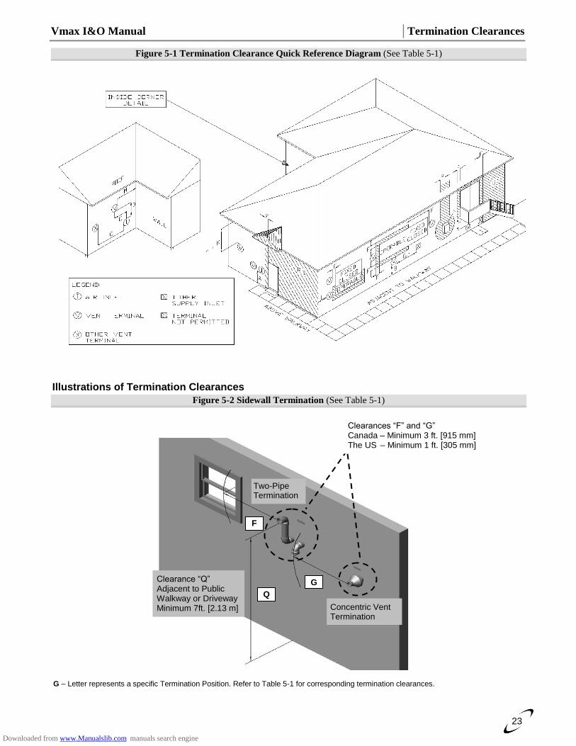
Figure 5-1 Termination Clearance Quick Reference Diagram (See Table 5-1)
Illustrations of Termination Clearances
Figure 5-2 Sidewall Termination (See Table 5-1)
G – Letter represents a specific Termination Position. Refer to Table 5-1 for corresponding termination clearances.
Concentric Vent Termination
Q
Two-Pipe Termination
F
Clearance “Q” Adjacent to Public Walkway or Driveway Minimum 7ft. [2.13 m]
G
Clearances “F” and “G” Canada – Minimum 3 ft. [915 mm] The US – Minimum 1 ft. [305 mm]
Downloaded from www.Manualslib.com manuals search engine
Termination Clearances │ Vmax I&O Manual
24
Extra precaution must be taken to adequately support the weight of the Vent/Air-inlet
piping in applications using roof-top terminations. Failure to follow these instructions
may result in venting or boiler component failure resulting in flue gas spillage leading to
property damage, serious injury or death.
Under no circumstances may an existing chimney or chase-way be used to vent or
provide combustion intake air to a Vmax VM110 or VM110P. Failure to follow these
instructions will result in fire, property damage, serious injury or death.
Removing an Existing Boiler from Common Venting System
Do not install the Vmax VM110 or VM110P into a common venting system with any
other boiler. Failure to comply with this warning will cause flue gas spillage and leech
carbon monoxide emissions into the surrounding air resulting in serious injury or death.
When an existing boiler is removed from a common venting system, the common venting
system is likely to be too large for proper venting of the remaining boilers connected to
it. Instructions have been provided on how to remove the existing boiler and how to
resize the remaining venting system. Failure to follow these instructions may result in
property damage, serious injury or death.
Upon removal of an existing boiler, the following steps shall be followed for each boiler remaining in the
common venting system; prior to commencing this procedure, shutdown all boilers remaining in the common
venting system.
Steps to Removing an Existing Boiler:
1. Seal any unused openings in the common venting system.
2. Visually inspect the venting system for proper size and horizontal pitch. Verify that there is no blockage,
restriction, leakage, corrosion or other deficiencies which could cause an unsafe condition.
3. Insofar as is practical, close fireplace dampers, all building doors and windows and all doors between the
space in which the boilers remaining connected to the common venting system are located and other spaces
of the building. Turn on clothes dryers and any boiler not connected to the common venting system. Turn on
any exhaust fans, such as range hoods and bathroom exhausts, so they will operate at maximum speed. Do
not operate a summer exhaust fan.
4. Place in operation the boiler being inspected. Follow the applicable lighting instructions. Adjust thermostat
so boiler will operate continuously.
5. Test for spillage at the draft hood relief opening after 5 minutes of main burner operation. Use the flame of a
match or candle, or smoke from a cigarette, cigar or pipe.
6. After it has been determined that each boiler remaining connected to the common venting system properly
vents when tested as outlined above, return doors, windows, exhaust fans, fireplace dampers and any other
gas burning boiler to their previous condition of use.
7. Any improper operation of the common venting system should be corrected so the installation conforms to
the National Fuel Gas Code, ANSI Z223.1/NFPA 54 and/or CAN/CSA B149.1, Natural Gas and Propane
Installation Code. When resizing any portion of the common venting system, the common venting system
should be resized to approach the minimum size as determined using the appropriate tables in Part 11 of the
National Fuel Gas Code, ANSI Z223.1/NFPA 54 and/or CAN/CSA B149.1, Natural Gas and Propane
Installation Code.
Downloaded from www.Manualslib.com manuals search engine
Vmax I&O Manual │Condensate Drain
25
6.0 CONDENSATE DRAIN
The Vmax boiler produces liquid condensate in the heat exchanger and venting system as a product of
combustion. Steps must be taken to ensure condensate does not collect in the venting system; therefore, all
exhaust piping must slope back to the boiler a minimum ¼ in. per linear foot of vent. Condensate must be
drained from the unit into a household drain.
Check with your municipality, or local gas company to determine if the disposal of
combustion condensate is permitted in your area (e.g. in the State of Massachusetts the
condensate must be neutralized prior to entering a drain).
The following are important notes that must be taken into consideration when constructing the condensate drain
system (see Condensate Trap Installation Instructions for further details):
DO NOT install condensate lines outside. A frozen or blocked drain will cause the condensate to back-up
and leak. This may result in damage to boiler components resulting in a no heat condition; property damage
may also occur.
NEVER use copper, steel, or galvanized piping in the construction of the condensate system (condensate is
very corrosive and will corrode most metals).
When a condensate pump is used or required, select a pump that is designed for residential furnaces.
All tubing, drains and surfaces that come in contact with condensate draining from the
boiler, must be constructed out of corrosion resistant material; copper, steel and
galvanized are not acceptable materials for draining condensate. Failure to abide by this
caution will result in property damage.
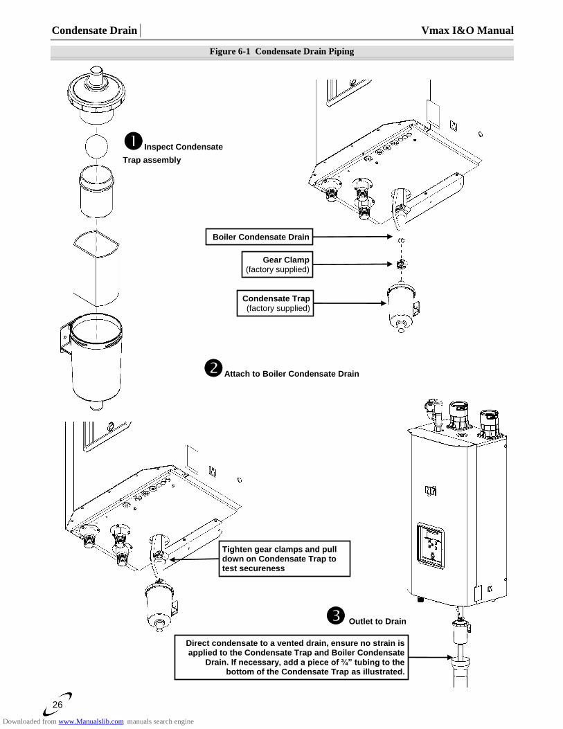
Condensate Trap Installation Instructions (see Figure 6-1) (Note: the Condensate Trap is factory supplied with the boiler and must be field installed)
1. Inspect Condensate Trap Assembly – Inspect the Condensate Trap to ensure all parts were shipped with
the assembly (see Figure 6-1). The Condensate Trap must be periodically disassembled and cleaned as part
of a regular maintenance plan.
2. Attach to Boiler Condensate Drain – Insert the inlet fitting of the Condensate Trap into the boiler
condensate drain; secure with the factory supplied gear clamp (see Figure 6-1). Pull down on the Condensate
Trap and ensure that it remains securely fastened.
3. Outlet to Drain – Direct condensate from the outlet of the Condensate Trap to a household drain,
condensate pump or neutralizer (check with your local authority regarding the disposal of condensate). If
necessary connect suitable ¾” tubing to the bottom of the Condensate Trap and route it to drain, being
careful NOT to route it higher than the Condensate Trap outlet (see Figure 6-1).
The Condensate Trap must be periodically disassembled and cleaned as part of a regular
maintenance plan. Failure to clean the trap regularly can cause condensate drain blockage
leading to boiler malfunction, property damage and even personal injury.
Carefully follow the above instructions and the accompanying figure – check to ensure
the condensate trap is secure to the bottom of the boiler and that no strain is placed on it.
Failure to install the condensate trap properly will result in flue gas spillage and leeching
of carbon monoxide emissions into the surroundings resulting in serious injury or death.
Downloaded from www.Manualslib.com manuals search engine
Condensate Drain│ Vmax I&O Manual
26
Figure 6-1 Condensate Drain Piping
Inspect Condensate
Trap assembly
Attach to Boiler Condensate Drain
Condensate Trap (factory supplied)
Outlet to Drain
Gear Clamp (factory supplied)
Boiler Condensate Drain
Direct condensate to a vented drain, ensure no strain is applied to the Condensate Trap and Boiler Condensate
Drain. If necessary, add a piece of ¾” tubing to the bottom of the Condensate Trap as illustrated.
Tighten gear clamps and pull down on Condensate Trap to test secureness
Downloaded from www.Manualslib.com manuals search engine
Vmax I&O Manual │Lighting the Boiler
27
7.0 INSTALLING GAS PIPING
The Vmax VM110 & VM110P are factory equipped to operate with Natural Gas, the installation of a conversion kit is required prior to operating with Propane Gas. The
Natural to LP Conversion Kit (see Table 7-1) must be installed prior to installing the gas piping to the boiler. Failure to properly convert the unit to operate with Propane may result in property damage, serious injury or death.
Liquefied Petroleum (LP) propane gas is heavier than air. Do not install the boiler in a pit or similar location that will permit heavier than air gas to collect. Check with Local
Codes as they may require boilers fueled with LP gas to be provided with an approved means of removing unburned gases from the room. Failure to follow these instructions may result in serious injury or death.
Table 7-1 Natural to LP Propane Conversion Kit
Kit Number LP Orifice Size Orifice Part Number
84867-4 5.05 mm 84795
Installation Refer to the current National Fuel Gas Code ANSI Z223.1/NFPA 54 or CAN/CGA B149.1 installation codes, and local codes for gas piping requirements and sizing. Pipe size running to the unit depends on: Length of pipe. Number of fittings. Type of gas. Maximum input requirement of all gas boilers in the residence.
Ensure that:
The gas line connection to the boiler does not apply any weight to the gas valve. NTI recommends using approved flexible gas piping (if acceptable by local codes) to connect the boiler to the gas supply (see Figure 7-1 for details).
You plan the installation so the piping does not interfere with the vent pipe, or the removal of the valve, burner, and serviceable components.
The Boiler is installed such that the gas ignition system components are protected from water (dripping, spraying, rain etc.) during installation and servicing.
The gas piping is large enough for all the gas appliances in the home. No appreciable drop in line pressure should occur when any unit (or combination of units) lights or runs. Use common gas-line sizing practices.
Always use a pipe-threading compound that is resistant to Propane (LP) gas solvent action. Apply sparingly to all male threads, starting at two threads from the end. Over doping or applying dope to the female end, can result in a blocked gas line.
DO NOT TIGHTEN FITTINGS WITHOUT SUPPORTING THE INTERNAL GAS LINE CONNECTION WITHIN THE BOILER as damage to the boiler’s internal gas carrying components could occur.
Install a manual “Equipment Shut-Off Valve” as shown in Figure 7-1. Valve must be listed by a nationally recognized testing laboratory.
The gas line piping can safely be removed from the boiler for servicing, by strategically placing the gas line shutoff and union; see example in Figure 7-1.
All gas piping, including gas components in the boiler, are checked for leaks using a “Bubble Test”, prior to operating the boiler.
Strain on the gas valve and fittings may result in vibration, premature component failure
and leakage and may result in a fire, explosion, property damage, serious injury or death.
Do not use an open flame to test for gas leaks. Failure to follow these instructions may
result in fire, property damage, serious injury or death.
When performing a pressure test on the gas line piping, be sure the boiler is disconnected
or isolated if the test pressure is expected to exceed 1/2 PSI (14 in. w.c.), as damage to the
gas valve could occur resulting in fire, property damage, serious injury or death.
Downloaded from www.Manualslib.com manuals search engine
Lighting the Boiler│ Vmax I&O Manual
28
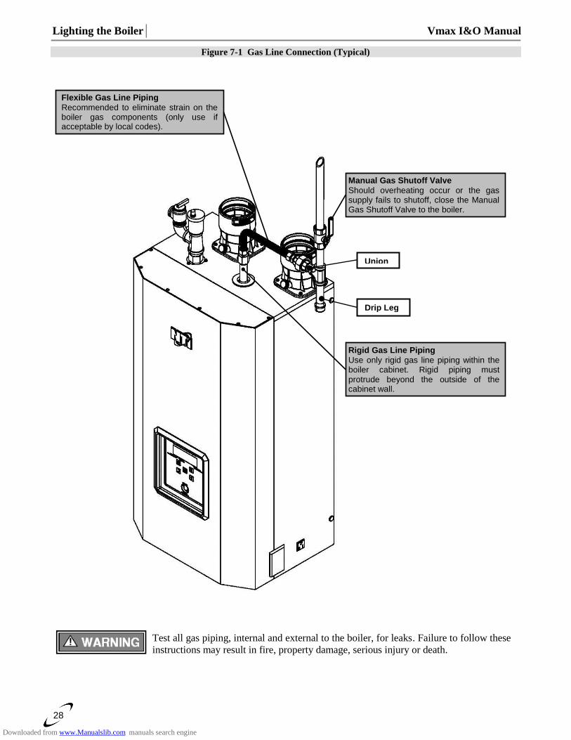
Figure 7-1 Gas Line Connection (Typical)
Test all gas piping, internal and external to the boiler, for leaks. Failure to follow these
instructions may result in fire, property damage, serious injury or death.
Union
Manual Gas Shutoff Valve
Should overheating occur or the gas supply fails to shutoff, close the Manual Gas Shutoff Valve to the boiler.
Flexible Gas Line Piping
Recommended to eliminate strain on the boiler gas components (only use if acceptable by local codes).
Rigid Gas Line Piping
Use only rigid gas line piping within the boiler cabinet. Rigid piping must protrude beyond the outside of the cabinet wall.
Drip Leg
Downloaded from www.Manualslib.com manuals search engine
Vmax I&O Manual │Lighting the Boiler
29
8.0 LIGHTING THE BOILER
Before Start-up refer to Mandatory Pre-commissioning Procedure for Plastic Venting
in Section 4.0. Failure to follow these instructions can result in explosions, injury or death.
Prior to turning the gas supply on and lighting the boiler, ensure all aspects of the installation are complete and in conformance with the instructions provided in this
manual, including the Vent/Air-inlet, Condensate Drain, and System Water Piping. Failure to precisely follow these instructions will cause a fire or explosion resulting in property damage, serious injury or death.
Do not store or use gasoline or other flammable vapors & liquids in the vicinity of this or any other boiler. Failure to follow instructions could result in explosion causing property damage, serious injury or death.
If you do not follow these instructions exactly, a fire or explosion may result causing
property damage, serious injury or death.
Should overheating occur or the gas supply fails to shutoff, close the Manual Gas Shutoff Valve to the boiler. Failure to follow instructions could result in explosion causing property damage, serious injury or death.
FOR YOUR SAFETY, READ BEFORE OPERATING_
A) This boiler does not have a pilot. It is equipped with an ignition device which automatically lights the burner. Do not try to light the burner by hand. B) BEFORE OPERATING smell all around the boiler area for gas. Be sure to smell next to the floor because some gas is heavier than air and will settle on the floor. WHAT TO DO IF YOU SMELL GAS: • Do not try to light any boiler. • Do not touch any electric switch. • Do not use any phone in your building. • Immediately call your gas supplier from a neighbor's phone. Follow the gas supplier's instructions. • If you cannot reach your gas supplier, call the fire department. C) Use only your hand to turn the gas “shutoff” valve. Never use tools. If the handle will not turn by hand, do
not try to repair it, call a qualified service technician. Force or attempted repair may result in a fire or explosion.
D) Do not use this boiler if any part has been under water. Immediately call a qualified service technician
to inspect the boiler and to replace any part of the control system and any gas control which has been
under water.
OPERATING INSTRUCTIONS_
1. STOP! Read the safety information above very carefully. 2. Set the thermostat to lowest setting. Turn off all electric power to the boiler. 3. This boiler does not have a pilot. It is equipped with an ignition device which automatically lights the burner. Do not try to light the burner by hand. 4. Turn the manual gas valve to the OFF position. Remove front access panel. 5. Wait five (5) minutes to clear out any gas. Then smell for gas, including near the floor. If you smell gas, STOP! Follow “B” in the safety information above. If you do not smell gas, go to the next step. 6. Turn the manual gas valve ON. Wait an additional five (5) minutes smelling for gas. 7. Replace the front access panel. 8. Set thermostat to highest setting. Turn on all electric power to the boiler. 9. Ignition sequence is automatic. Combustion will occur after a brief fan purge. 10. If ignition does not occur, follow the instructions “To Turn Off Gas To Boiler” and call your service technician or gas supplier.
TO TURN OFF GAS TO THE BOILER_
1. STOP! Read the safety information above very carefully. 2. Turn off all electric power to the boiler 3. Turn the manual gas valve to the OFF position
Downloaded from www.Manualslib.com manuals search engine
Lighting the Boiler│ Vmax I&O Manual
30
The initial lighting of the boiler must be performed by a licensed Gas Technician.
Failure to follow instructions may result in property damage, serious injury or death.
Ensure the boiler is wired in accordance with this manual.
Ensure the gas shutoff valve is turned on, and that the gas system has been fully tested for leaks.
Ensure the system is completely filled with water, and that ALL the air is purged out.
Ensure the Vent and Air-inlet piping is completely installed in accordance with this manual.
Allow primers/cements to cure for 8 hours prior to Start-up. If curing time is less than 8
hours, first perform Steps 2 through 6 of Mandatory Pre-commissioning Procedure for
Plastic Venting in Section 4.0. Failure to follow these instructions can result in explosion,
serious injury or death.
Initial Start-Up
Each time the power is turned on to the boiler, the control will go through a “de-air” sequence designed to
purge air from the boiler. The de-air sequence takes 14 minutes to execute, during which time the circulators
will be operating in a cyclical manner and the burner will not attempt to function. Once the de-air sequence
has been executed at least once, subsequent de-air sequences can be bypassed by holding the “OK” button
until “de-Air” is no longer displayed on the screen; see Section 17.0 for more details.
1. Turn on power to the Vmax VM110 or VM110P and turn-up the Thermostat(s). The boiler should run
through a purge, and combustion should occur. (The control system has a built-in ignition retry, allowing the
system to try at least five times, before locking-out.)
2. With the unit operating at full capacity, verify that the gas line pressure is 4-10.5 inches w.c. for Natural gas,
and 9-13 inches w.c. for Propane (see Section 9.0 for details).
3. Using an appropriate Oxygen (O2) or Carbon Dioxide (CO2) analyzer, take a sample of the flue gas. The
sample must fall within the acceptable ranges for CO2 (see Section 9.0 for details).
4. Perform at least three ignitions in succession to ensure proper operation.
5. After the three successive ignitions, unplug the flame sensor and allow the unit to cycle again. The flame
safety system will allow the unit to go through 5 ignition cycles before going to “Loc 1”. Once you have
confirmed this behavior, reinstall the wire on the flame sensor, press the reset button and reconfirm proper
ignition.
The flame probe is located in the burner plate; it has a single white/semi-transparent wire
connected to it. DO NOT remove the orange spark cable from the ignition electrode (also
located in the burner plate); this device is used for spark ignition and produces 20,000 Volts potential which
would result in an EXTREME ELECTRICAL SHOCK possibly causing serious injury or death.
If the unit fails to light consistently and smoothly, contact NTI for technical assistance at
1-800-688-2575. Never allow the boiler to operate if the ignition or operation of the
burner is rough or erratic. Failure to follow these instructions may result in serious injury or death.
Re-lighting Unit
1. Stop and read these instructions very carefully.
2. Set the thermostat to the lowest setting, and then turn off all power to the boiler.
3. This boiler does not have a pilot. It is equipped with an ignition device that automatically lights the burner.
Do not try to light the burner by hand.
4. Turn the gas shutoff valve to the off position, and then remove the front cover.
5. Wait five (5) minutes to clear out any gas. Then check for gas, including near the floor. If you smell gas
“Stop” and follow “B” above (see FOR YOUR SAFETY, READ BEFORE OPERATING). If you do
not detect any gas proceed to the next step.
6. Turn the gas shutoff valve to the on position, wait an addition five (5) minutes and check for gas.
7. Replace the front cover.
8. Set the thermostat to the highest setting, and then turn on all power to the boiler.
9. Ignition sequence is automatic, combustion will occur after a brief fan purge. Ignition will retry 3 times.
10. If ignition does not occur, “Turn off the gas and electricity to the boiler” and contact a qualified service
technician, or gas supplier.
Downloaded from www.Manualslib.com manuals search engine
Vmax I&O Manual │Lighting the Boiler
31
Turning Off the Boiler
1. Set the thermostat to the lowest setting, and then turn off all power to the boiler.
2. Turn the gas shutoff valve to the off position.
Downloaded from www.Manualslib.com manuals search engine
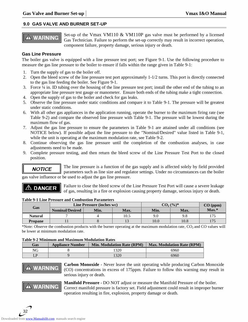
Gas Valve and Burner Set-up │ Vmax I&O Manual
32
9.0 GAS VALVE AND BURNER SET-UP
Set-up of the Vmax VM110 & VM110P gas valve must be performed by a licensed
Gas Technician. Failure to perform the set-up correctly may result in incorrect operation,
component failure, property damage, serious injury or death.
Gas Line Pressure
The boiler gas valve is equipped with a line pressure test port; see Figure 9-1. Use the following procedure to
measure the gas line pressure to the boiler to ensure if falls within the range given in Table 9-1:
1. Turn the supply of gas to the boiler off. 2. Open the bleed screw of the line pressure test port approximately 1-1/2 turns. This port is directly connected
to the gas line feeding the boiler. See Figure 9-1. 3. Force ¼ in. ID tubing over the housing of the line pressure test port; install the other end of the tubing to an
appropriate line pressure test gauge or manometer. Ensure both ends of the tubing make a tight connection. 4. Open the supply of gas to the boiler and check for gas leaks. 5. Observe the line pressure under static conditions and compare it to Table 9-1. The pressure will be greatest
under static conditions. 6. With all other gas appliances in the application running, operate the burner to the maximum firing rate (see
Table 9-2) and compare the observed line pressure with Table 9-1. The pressure will be lowest during the maximum flow of gas.
7. Adjust the gas line pressure to ensure the parameters in Table 9-1 are attained under all conditions (see NOTICE below). If possible adjust the line pressure to the "Nominal/Desired" value listed in Table 9-1, while the unit is operating at the maximum modulation rate, see Table 9-2.
8. Continue observing the gas line pressure until the completion of the combustion analyses, in case adjustments need to be made.
9. Complete pressure testing, and then return the bleed screw of the Line Pressure Test Port to the closed position.
The line pressure is a function of the gas supply and is affected solely by field provided
parameters such as line size and regulator settings. Under no circumstances can the boiler
gas valve influence or be used to adjust the gas line pressure.
Failure to close the bleed screw of the Line Pressure Test Port will cause a severe leakage
of gas, resulting in a fire or explosion causing property damage, serious injury or death.
Table 9-1 Line Pressure and Combustion Parameters
Gas Line Pressure (inches wc) CO2 (%)* CO (ppm)
Max.* Nominal/Desired Min. Max. Min. Max.
Natural 7 4 10.5 9.0 9.8 175
Propane 11 8 13 10.0 10.8 175
*Note: Observe the combustion products with the burner operating at the maximum modulation rate, CO2 and CO values will
be lower at minimum modulation rate.
Table 9-2 Minimum and Maximum Modulation Rates
Gas Appliance Number Min. Modulation Rate (RPM) Max. Modulation Rate (RPM)
NG 8 1320 6960
LP 9 1320 6960
Carbon Monoxide - Never leave the unit operating while producing Carbon Monoxide
(CO) concentrations in excess of 175ppm. Failure to follow this warning may result in
serious injury or death.
Manifold Pressure - DO NOT adjust or measure the Manifold Pressure of the boiler.
Correct manifold pressure is factory set. Field adjustment could result in improper burner
operation resulting in fire, explosion, property damage or death.
Downloaded from www.Manualslib.com manuals search engine
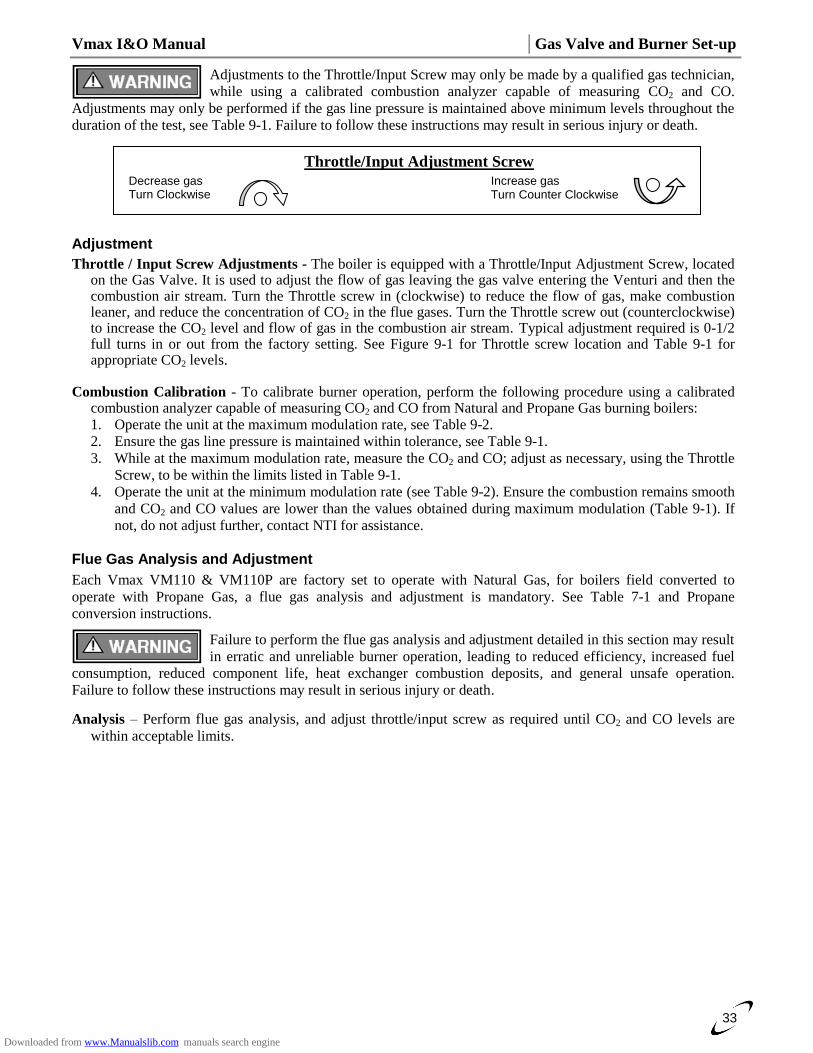
Vmax I&O Manual │Gas Valve and Burner Set-up
33
Adjustments to the Throttle/Input Screw may only be made by a qualified gas technician,
while using a calibrated combustion analyzer capable of measuring CO2 and CO.
Adjustments may only be performed if the gas line pressure is maintained above minimum levels throughout the
duration of the test, see Table 9-1. Failure to follow these instructions may result in serious injury or death.
Adjustment
Throttle / Input Screw Adjustments - The boiler is equipped with a Throttle/Input Adjustment Screw, located on the Gas Valve. It is used to adjust the flow of gas leaving the gas valve entering the Venturi and then the combustion air stream. Turn the Throttle screw in (clockwise) to reduce the flow of gas, make combustion leaner, and reduce the concentration of CO2 in the flue gases. Turn the Throttle screw out (counterclockwise) to increase the CO2 level and flow of gas in the combustion air stream. Typical adjustment required is 0-1/2 full turns in or out from the factory setting. See Figure 9-1 for Throttle screw location and Table 9-1 for appropriate CO2 levels.
Combustion Calibration - To calibrate burner operation, perform the following procedure using a calibrated
combustion analyzer capable of measuring CO2 and CO from Natural and Propane Gas burning boilers: 1. Operate the unit at the maximum modulation rate, see Table 9-2.
2. Ensure the gas line pressure is maintained within tolerance, see Table 9-1.
3. While at the maximum modulation rate, measure the CO2 and CO; adjust as necessary, using the Throttle
Screw, to be within the limits listed in Table 9-1.
4. Operate the unit at the minimum modulation rate (see Table 9-2). Ensure the combustion remains smooth
and CO2 and CO values are lower than the values obtained during maximum modulation (Table 9-1). If
not, do not adjust further, contact NTI for assistance.
Flue Gas Analysis and Adjustment
Each Vmax VM110 & VM110P are factory set to operate with Natural Gas, for boilers field converted to
operate with Propane Gas, a flue gas analysis and adjustment is mandatory. See Table 7-1 and Propane
conversion instructions.
Failure to perform the flue gas analysis and adjustment detailed in this section may result
in erratic and unreliable burner operation, leading to reduced efficiency, increased fuel
consumption, reduced component life, heat exchanger combustion deposits, and general unsafe operation.
Failure to follow these instructions may result in serious injury or death.
Analysis – Perform flue gas analysis, and adjust throttle/input screw as required until CO2 and CO levels are
within acceptable limits.
Throttle/Input Adjustment Screw
Increase gas Turn Counter Clockwise
Decrease gas Turn Clockwise
Downloaded from www.Manualslib.com manuals search engine
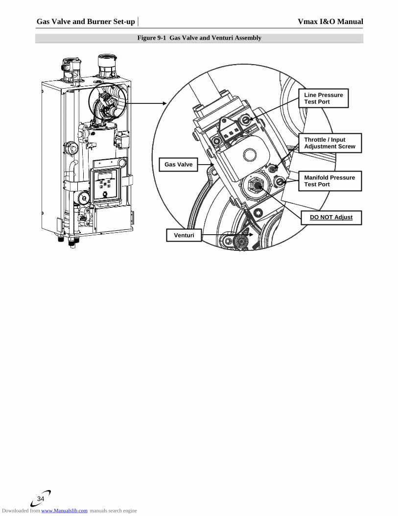
Gas Valve and Burner Set-up │ Vmax I&O Manual
34
Figure 9-1 Gas Valve and Venturi Assembly
DO NOT Adjust
Gas Valve
Manifold Pressure Test Port
Throttle / Input Adjustment Screw
Line Pressure Test Port
Venturi
Downloaded from www.Manualslib.com manuals search engine
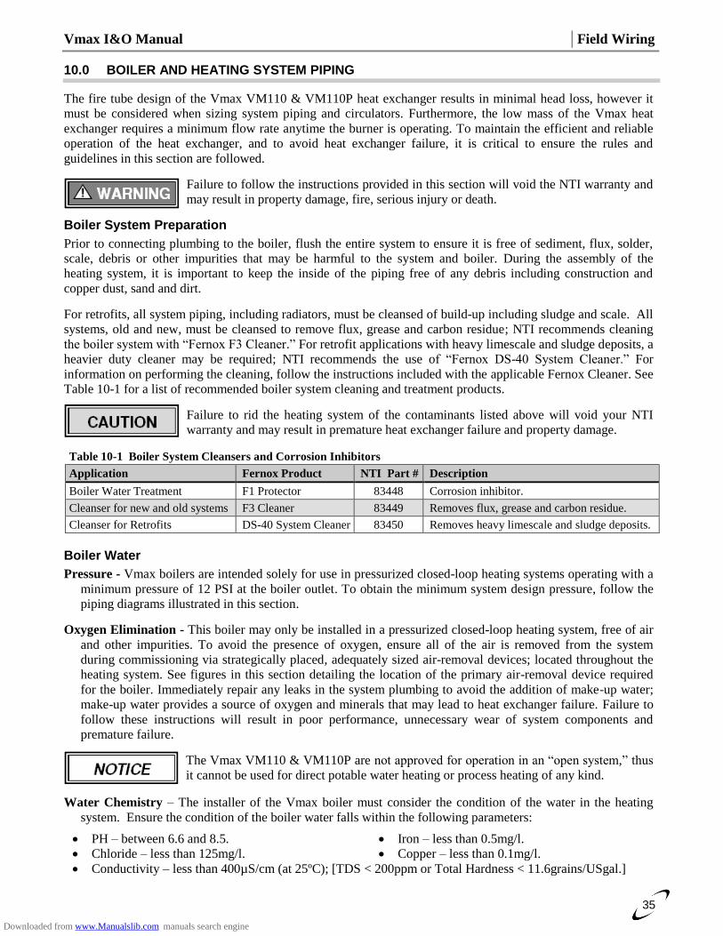
Vmax I&O Manual │Field Wiring
35
10.0 BOILER AND HEATING SYSTEM PIPING
The fire tube design of the Vmax VM110 & VM110P heat exchanger results in minimal head loss, however it
must be considered when sizing system piping and circulators. Furthermore, the low mass of the Vmax heat
exchanger requires a minimum flow rate anytime the burner is operating. To maintain the efficient and reliable
operation of the heat exchanger, and to avoid heat exchanger failure, it is critical to ensure the rules and
guidelines in this section are followed.
Failure to follow the instructions provided in this section will void the NTI warranty and
may result in property damage, fire, serious injury or death.
Boiler System Preparation
Prior to connecting plumbing to the boiler, flush the entire system to ensure it is free of sediment, flux, solder,
scale, debris or other impurities that may be harmful to the system and boiler. During the assembly of the
heating system, it is important to keep the inside of the piping free of any debris including construction and
copper dust, sand and dirt.
For retrofits, all system piping, including radiators, must be cleansed of build-up including sludge and scale. All
systems, old and new, must be cleansed to remove flux, grease and carbon residue; NTI recommends cleaning
the boiler system with “Fernox F3 Cleaner.” For retrofit applications with heavy limescale and sludge deposits, a
heavier duty cleaner may be required; NTI recommends the use of “Fernox DS-40 System Cleaner.” For
information on performing the cleaning, follow the instructions included with the applicable Fernox Cleaner. See
Table 10-1 for a list of recommended boiler system cleaning and treatment products.
Failure to rid the heating system of the contaminants listed above will void your NTI
warranty and may result in premature heat exchanger failure and property damage.
Table 10-1 Boiler System Cleansers and Corrosion Inhibitors
Application Fernox Product NTI Part # Description
Boiler Water Treatment F1 Protector 83448 Corrosion inhibitor.
Cleanser for new and old systems F3 Cleaner 83449 Removes flux, grease and carbon residue.
Cleanser for Retrofits DS-40 System Cleaner 83450 Removes heavy limescale and sludge deposits.
Boiler Water
Pressure - Vmax boilers are intended solely for use in pressurized closed-loop heating systems operating with a
minimum pressure of 12 PSI at the boiler outlet. To obtain the minimum system design pressure, follow the
piping diagrams illustrated in this section.
Oxygen Elimination - This boiler may only be installed in a pressurized closed-loop heating system, free of air
and other impurities. To avoid the presence of oxygen, ensure all of the air is removed from the system
during commissioning via strategically placed, adequately sized air-removal devices; located throughout the
heating system. See figures in this section detailing the location of the primary air-removal device required
for the boiler. Immediately repair any leaks in the system plumbing to avoid the addition of make-up water;
make-up water provides a source of oxygen and minerals that may lead to heat exchanger failure. Failure to
follow these instructions will result in poor performance, unnecessary wear of system components and
premature failure.
The Vmax VM110 & VM110P are not approved for operation in an “open system,” thus
it cannot be used for direct potable water heating or process heating of any kind.
Water Chemistry – The installer of the Vmax boiler must consider the condition of the water in the heating
system. Ensure the condition of the boiler water falls within the following parameters:
PH – between 6.6 and 8.5. Iron – less than 0.5mg/l.
Chloride – less than 125mg/l. Copper – less than 0.1mg/l.
Conductivity – less than 400µS/cm (at 25ºC); [TDS < 200ppm or Total Hardness < 11.6grains/USgal.]
Downloaded from www.Manualslib.com manuals search engine
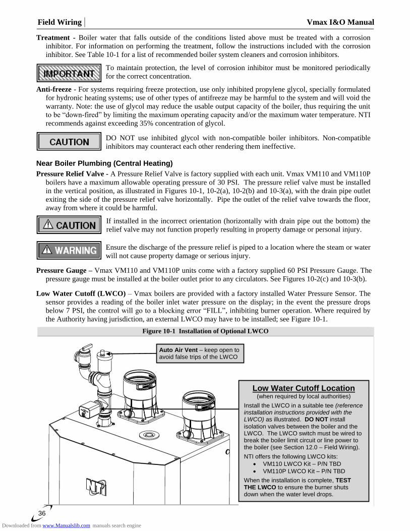
Field Wiring │ Vmax I&O Manual
36
Treatment - Boiler water that falls outside of the conditions listed above must be treated with a corrosion
inhibitor. For information on performing the treatment, follow the instructions included with the corrosion
inhibitor. See Table 10-1 for a list of recommended boiler system cleaners and corrosion inhibitors.
To maintain protection, the level of corrosion inhibitor must be monitored periodically
for the correct concentration.
Anti-freeze - For systems requiring freeze protection, use only inhibited propylene glycol, specially formulated
for hydronic heating systems; use of other types of antifreeze may be harmful to the system and will void the
warranty. Note: the use of glycol may reduce the usable output capacity of the boiler, thus requiring the unit
to be “down-fired” by limiting the maximum operating capacity and/or the maximum water temperature. NTI
recommends against exceeding 35% concentration of glycol.
DO NOT use inhibited glycol with non-compatible boiler inhibitors. Non-compatible
inhibitors may counteract each other rendering them ineffective.
Near Boiler Plumbing (Central Heating)
Pressure Relief Valve - A Pressure Relief Valve is factory supplied with each unit. Vmax VM110 and VM110P
boilers have a maximum allowable operating pressure of 30 PSI. The pressure relief valve must be installed
in the vertical position, as illustrated in Figures 10-1, 10-2(a), 10-2(b) and 10-3(a), with the drain pipe outlet
exiting the side of the pressure relief valve horizontally. Pipe the outlet of the relief valve towards the floor,
away from where it could be harmful.
If installed in the incorrect orientation (horizontally with drain pipe out the bottom) the
relief valve may not function properly resulting in property damage or personal injury.
Ensure the discharge of the pressure relief is piped to a location where the steam or water
will not cause property damage or serious injury.
Pressure Gauge – Vmax VM110 and VM110P units come with a factory supplied 60 PSI Pressure Gauge. The
pressure gauge must be installed at the boiler outlet prior to any circulators. See Figures 10-2(c) and 10-3(b).
Low Water Cutoff (LWCO) – Vmax boilers are provided with a factory installed Water Pressure Sensor. The
sensor provides a reading of the boiler inlet water pressure on the display; in the event the pressure drops
below 7 PSI, the control will go to a blocking error “FILL”, inhibiting burner operation. Where required by
the Authority having jurisdiction, an external LWCO may have to be installed; see Figure 10-1.
Figure 10-1 Installation of Optional LWCO
Low Water Cutoff Location
(when required by local authorities)
Install the LWCO in a suitable tee (reference installation instructions provided with the LWCO) as illustrated. DO NOT install
isolation valves between the boiler and the LWCO. The LWCO switch must be wired to break the boiler limit circuit or line power to the boiler (see Section 12.0 – Field Wiring).
NTI offers the following LWCO kits:
VM110 LWCO Kit – P/N TBD
VM110P LWCO Kit – P/N TBD
When the installation is complete, TEST THE LWCO to ensure the burner shuts down when the water level drops.
Auto Air Vent – keep open to avoid false trips of the LWCO
Downloaded from www.Manualslib.com manuals search engine
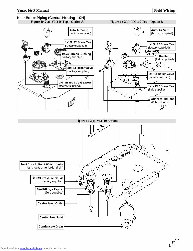
Vmax I&O Manual │Field Wiring
37
Near Boiler Piping (Central Heating – CH) Figure 10-2(a) VM110 Top – Option A Figure 10-2(b) VM110 Top – Option B
Figure 10-2(c) VM110 Bottom
Central Heat Outlet
Inlet from Indirect Water Heater (and location for boiler drain)
Condensate Drain
60 PSI Pressure Gauge (factory supplied)
Tee Fitting - Typical
(field supplied)
Central Heat Inlet
1x3/4” Brass Bushing (factory supplied)
30 PSI Relief Valve (factory supplied)
Auto Air Vent (factory supplied)
3/4” Brass Street Elbow (factory supplied)
1x1/2x1” Brass Tee (factory supplied)
1” Nipple (field supplied)
30 PSI Relief Valve (factory supplied)
Auto Air Vent (factory supplied)
1x1/2x1” Brass Tee (factory supplied)
1x1x3/4” Brass Tee (field supplied)
Outlet to Indirect Water Heater
Downloaded from www.Manualslib.com manuals search engine
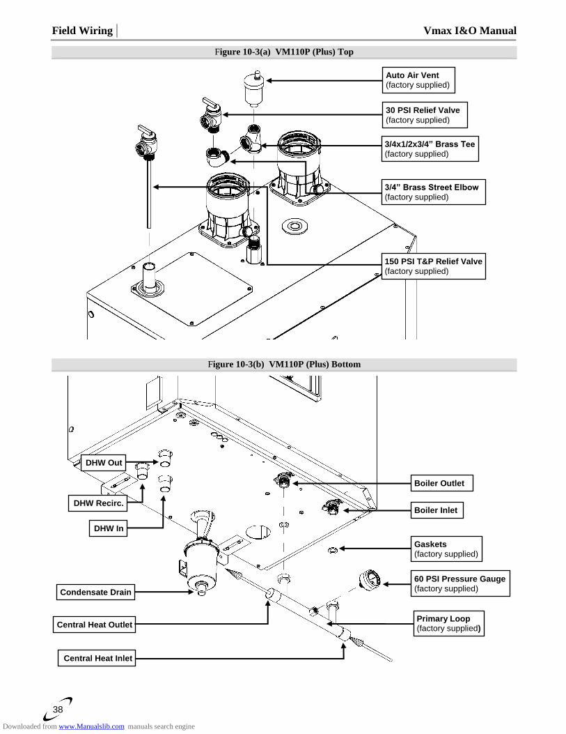
Field Wiring │ Vmax I&O Manual
38
Figure 10-3(a) VM110P (Plus) Top
Figure 10-3(b) VM110P (Plus) Bottom
DHW Out
60 PSI Pressure Gauge (factory supplied) Condensate Drain
Boiler Outlet
Primary Loop (factory supplied)
DHW Recirc.
Central Heat Inlet
Central Heat Outlet
DHW In
Gaskets (factory supplied)
Boiler Inlet
150 PSI T&P Relief Valve (factory supplied)
Auto Air Vent (factory supplied)
3/4x1/2x3/4” Brass Tee (factory supplied)
3/4” Brass Street Elbow (factory supplied)
30 PSI Relief Valve
(factory supplied)
Downloaded from www.Manualslib.com manuals search engine
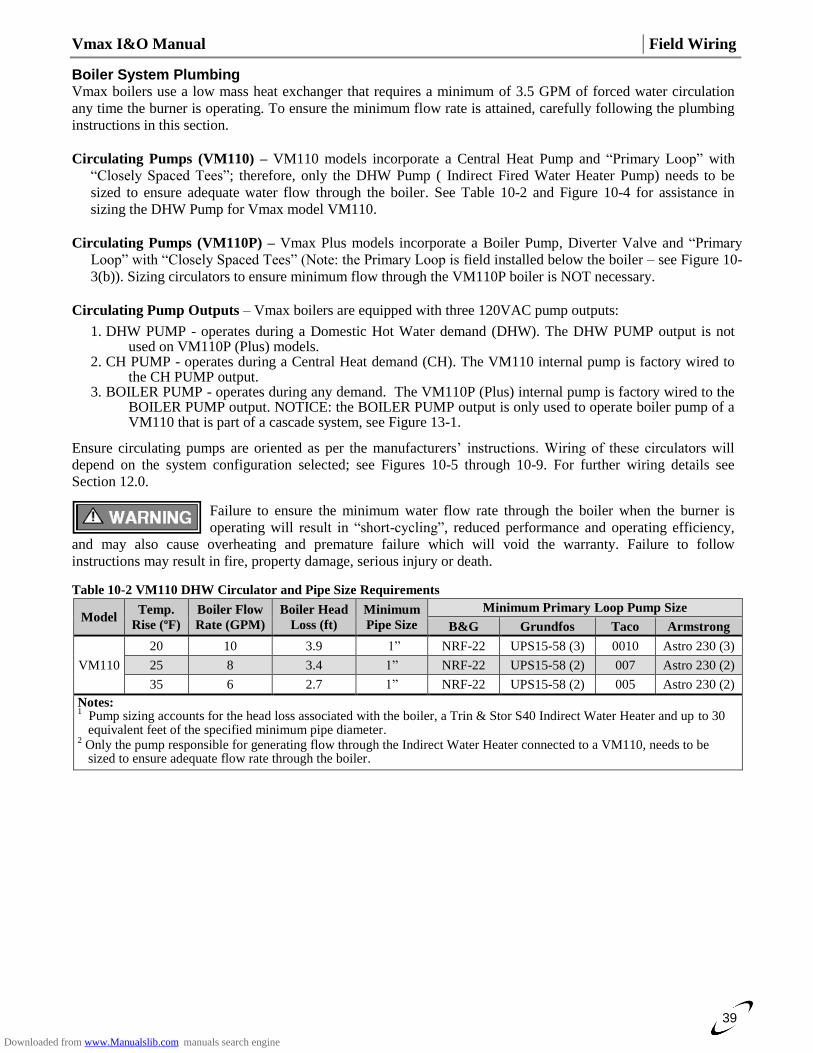
Vmax I&O Manual │Field Wiring
39
Boiler System Plumbing Vmax boilers use a low mass heat exchanger that requires a minimum of 3.5 GPM of forced water circulation
any time the burner is operating. To ensure the minimum flow rate is attained, carefully following the plumbing
instructions in this section.
Circulating Pumps (VM110) – VM110 models incorporate a Central Heat Pump and “Primary Loop” with
“Closely Spaced Tees”; therefore, only the DHW Pump ( Indirect Fired Water Heater Pump) needs to be
sized to ensure adequate water flow through the boiler. See Table 10-2 and Figure 10-4 for assistance in
sizing the DHW Pump for Vmax model VM110.
Circulating Pumps (VM110P) – Vmax Plus models incorporate a Boiler Pump, Diverter Valve and “Primary
Loop” with “Closely Spaced Tees” (Note: the Primary Loop is field installed below the boiler – see Figure 10-
3(b)). Sizing circulators to ensure minimum flow through the VM110P boiler is NOT necessary.
Circulating Pump Outputs – Vmax boilers are equipped with three 120VAC pump outputs:
1. DHW PUMP - operates during a Domestic Hot Water demand (DHW). The DHW PUMP output is not used on VM110P (Plus) models.
2. CH PUMP - operates during a Central Heat demand (CH). The VM110 internal pump is factory wired to the CH PUMP output.
3. BOILER PUMP - operates during any demand. The VM110P (Plus) internal pump is factory wired to the BOILER PUMP output. NOTICE: the BOILER PUMP output is only used to operate boiler pump of a VM110 that is part of a cascade system, see Figure 13-1.
Ensure circulating pumps are oriented as per the manufacturers’ instructions. Wiring of these circulators will
depend on the system configuration selected; see Figures 10-5 through 10-9. For further wiring details see
Section 12.0.
Failure to ensure the minimum water flow rate through the boiler when the burner is
operating will result in “short-cycling”, reduced performance and operating efficiency,
and may also cause overheating and premature failure which will void the warranty. Failure to follow
instructions may result in fire, property damage, serious injury or death.
Table 10-2 VM110 DHW Circulator and Pipe Size Requirements
Model Temp.
Rise (ºF)
Boiler Flow
Rate (GPM)
Boiler Head
Loss (ft)
Minimum
Pipe Size
Minimum Primary Loop Pump Size
B&G Grundfos Taco Armstrong
VM110
20 10 3.9 1”
NRF-22 UPS15-58 (3) 0010
Astro 230 (3)
25 8 3.4 1” NRF-22 UPS15-58 (2) 007 Astro 230 (2)
35 6 2.7 1” NRF-22 UPS15-58 (2) 005 Astro 230 (2)
Notes: 1 Pump sizing accounts for the head loss associated with the boiler, a Trin & Stor S40 Indirect Water Heater and up to 30 equivalent feet of the specified minimum pipe diameter.
2 Only the pump responsible for generating flow through the Indirect Water Heater connected to a VM110, needs to be sized to ensure adequate flow rate through the boiler.
Downloaded from www.Manualslib.com manuals search engine
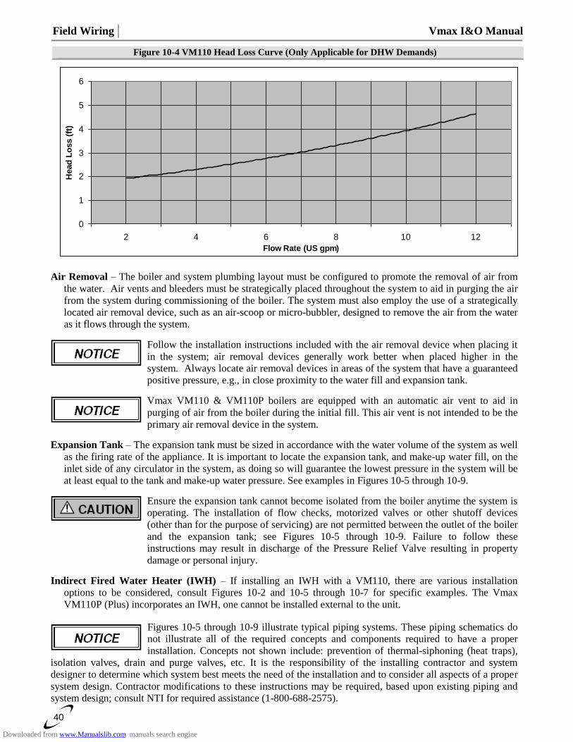
Field Wiring │ Vmax I&O Manual
40
Figure 10-4 VM110 Head Loss Curve (Only Applicable for DHW Demands)
0
1
2
3
4
5
6
2 4 6 8 10 12
Flow Rate (US gpm)
Head
Lo
ss (
ft)
Air Removal – The boiler and system plumbing layout must be configured to promote the removal of air from
the water. Air vents and bleeders must be strategically placed throughout the system to aid in purging the air
from the system during commissioning of the boiler. The system must also employ the use of a strategically
located air removal device, such as an air-scoop or micro-bubbler, designed to remove the air from the water
as it flows through the system.
Follow the installation instructions included with the air removal device when placing it
in the system; air removal devices generally work better when placed higher in the
system. Always locate air removal devices in areas of the system that have a guaranteed
positive pressure, e.g., in close proximity to the water fill and expansion tank.
Vmax VM110 & VM110P boilers are equipped with an automatic air vent to aid in
purging of air from the boiler during the initial fill. This air vent is not intended to be the
primary air removal device in the system.
Expansion Tank – The expansion tank must be sized in accordance with the water volume of the system as well
as the firing rate of the appliance. It is important to locate the expansion tank, and make-up water fill, on the
inlet side of any circulator in the system, as doing so will guarantee the lowest pressure in the system will be
at least equal to the tank and make-up water pressure. See examples in Figures 10-5 through 10-9.
Ensure the expansion tank cannot become isolated from the boiler anytime the system is
operating. The installation of flow checks, motorized valves or other shutoff devices
(other than for the purpose of servicing) are not permitted between the outlet of the boiler
and the expansion tank; see Figures 10-5 through 10-9. Failure to follow these
instructions may result in discharge of the Pressure Relief Valve resulting in property
damage or personal injury.
Indirect Fired Water Heater (IWH) – If installing an IWH with a VM110, there are various installation
options to be considered, consult Figures 10-2 and 10-5 through 10-7 for specific examples. The Vmax
VM110P (Plus) incorporates an IWH, one cannot be installed external to the unit.
Figures 10-5 through 10-9 illustrate typical piping systems. These piping schematics do
not illustrate all of the required concepts and components required to have a proper
installation. Concepts not shown include: prevention of thermal-siphoning (heat traps),
isolation valves, drain and purge valves, etc. It is the responsibility of the installing contractor and system
designer to determine which system best meets the need of the installation and to consider all aspects of a proper
system design. Contractor modifications to these instructions may be required, based upon existing piping and
system design; consult NTI for required assistance (1-800-688-2575).
Downloaded from www.Manualslib.com manuals search engine
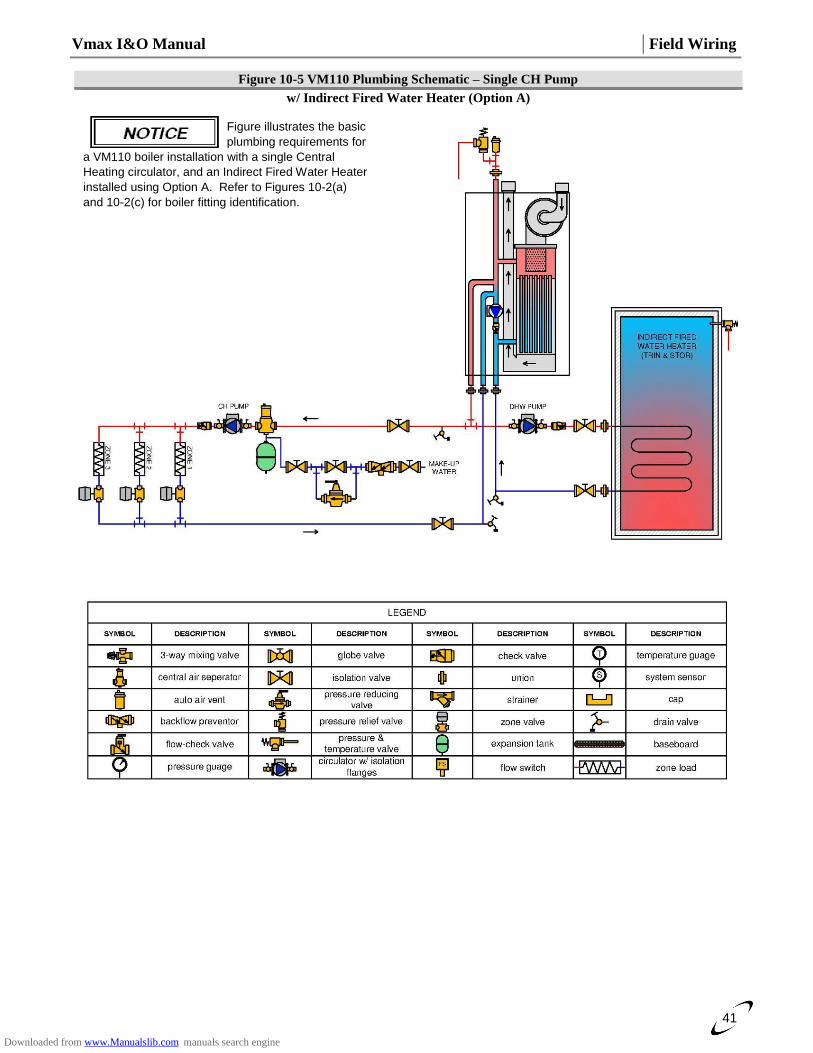
Vmax I&O Manual │Field Wiring
41
Figure 10-5 VM110 Plumbing Schematic – Single CH Pump
w/ Indirect Fired Water Heater (Option A)
Figure illustrates the basic
plumbing requirements for
a VM110 boiler installation with a single Central
Heating circulator, and an Indirect Fired Water Heater
installed using Option A. Refer to Figures 10-2(a)
and 10-2(c) for boiler fitting identification.
Downloaded from www.Manualslib.com manuals search engine
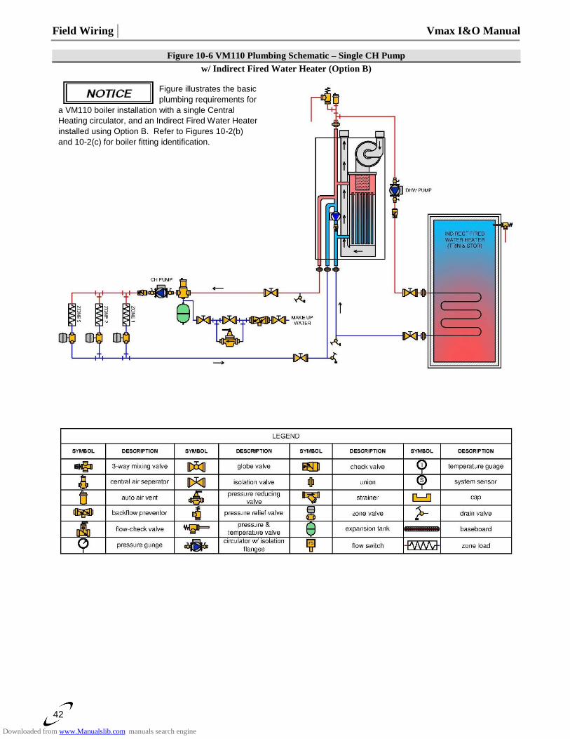
Field Wiring │ Vmax I&O Manual
42
Figure 10-6 VM110 Plumbing Schematic – Single CH Pump
w/ Indirect Fired Water Heater (Option B)
Figure illustrates the basic
plumbing requirements for
a VM110 boiler installation with a single Central
Heating circulator, and an Indirect Fired Water Heater
installed using Option B. Refer to Figures 10-2(b)
and 10-2(c) for boiler fitting identification.
Downloaded from www.Manualslib.com manuals search engine
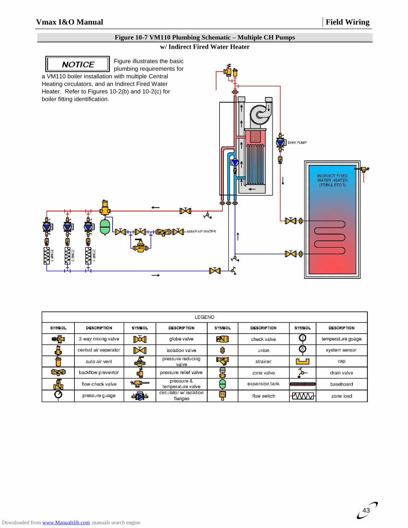
Vmax I&O Manual │Field Wiring
43
Figure 10-7 VM110 Plumbing Schematic – Multiple CH Pumps
w/ Indirect Fired Water Heater
Figure illustrates the basic
plumbing requirements for
a VM110 boiler installation with multiple Central
Heating circulators, and an Indirect Fired Water
Heater. Refer to Figures 10-2(b) and 10-2(c) for
boiler fitting identification.
Downloaded from www.Manualslib.com manuals search engine
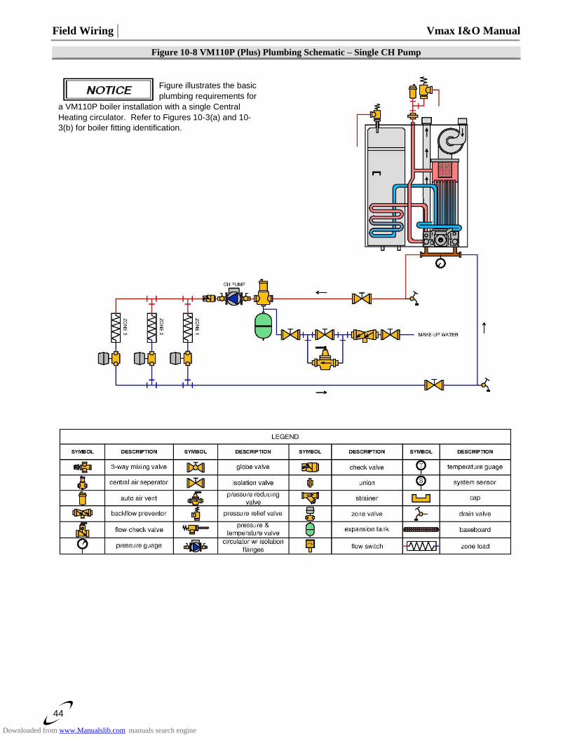
Field Wiring │ Vmax I&O Manual
44
Figure 10-8 VM110P (Plus) Plumbing Schematic – Single CH Pump
Figure illustrates the basic
plumbing requirements for
a VM110P boiler installation with a single Central
Heating circulator. Refer to Figures 10-3(a) and 10-
3(b) for boiler fitting identification.
Downloaded from www.Manualslib.com manuals search engine
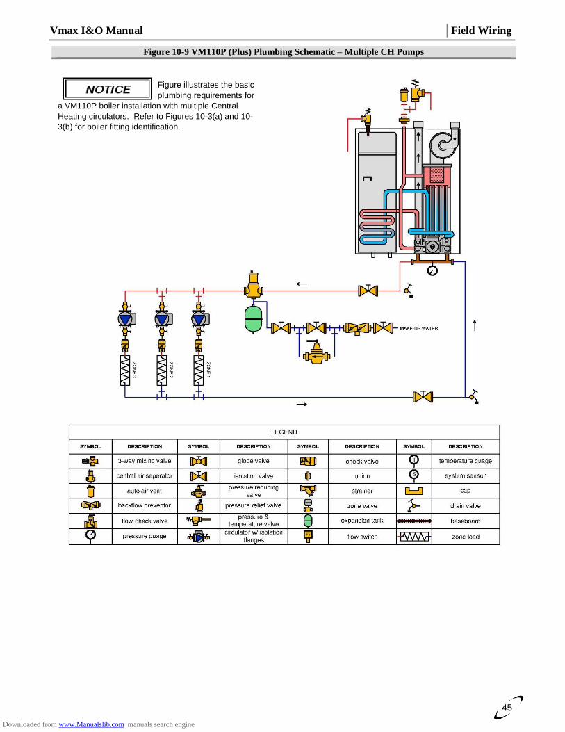
Vmax I&O Manual │Field Wiring
45
Figure 10-9 VM110P (Plus) Plumbing Schematic – Multiple CH Pumps
Figure illustrates the basic
plumbing requirements for
a VM110P boiler installation with multiple Central
Heating circulators. Refer to Figures 10-3(a) and 10-
3(b) for boiler fitting identification.
Downloaded from www.Manualslib.com manuals search engine
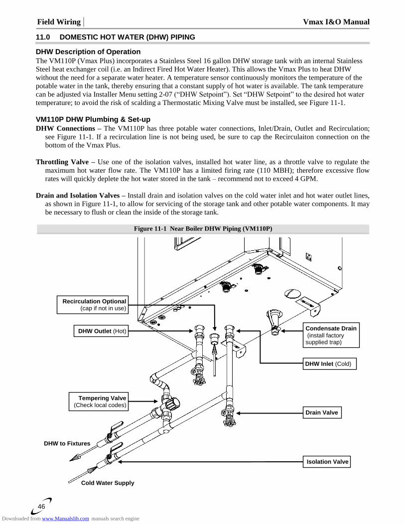
Field Wiring │ Vmax I&O Manual
46
11.0 DOMESTIC HOT WATER (DHW) PIPING
DHW Description of Operation
The VM110P (Vmax Plus) incorporates a Stainless Steel 16 gallon DHW storage tank with an internal Stainless
Steel heat exchanger coil (i.e. an Indirect Fired Hot Water Heater). This allows the Vmax Plus to heat DHW
without the need for a separate water heater. A temperature sensor continuously monitors the temperature of the
potable water in the tank, thereby ensuring that a constant supply of hot water is available. The tank temperature
can be adjusted via Installer Menu setting 2-07 (“DHW Setpoint”). Set “DHW Setpoint” to the desired hot water
temperature; to avoid the risk of scalding a Thermostatic Mixing Valve must be installed, see Figure 11-1.
VM110P DHW Plumbing & Set-up
DHW Connections – The VM110P has three potable water connections, Inlet/Drain, Outlet and Recirculation;
see Figure 11-1. If a recirculation line is not being used, be sure to cap the Recirculaiton connection on the
bottom of the Vmax Plus.
Throttling Valve – Use one of the isolation valves, installed hot water line, as a throttle valve to regulate the
maximum hot water flow rate. The VM110P has a limited firing rate (110 MBH); therefore excessive flow
rates will quickly deplete the hot water stored in the tank – recommend not to exceed 4 GPM.
Drain and Isolation Valves – Install drain and isolation valves on the cold water inlet and hot water outlet lines,
as shown in Figure 11-1, to allow for servicing of the storage tank and other potable water components. It may
be necessary to flush or clean the inside of the storage tank.
Figure 11-1 Near Boiler DHW Piping (VM110P)
DHW Outlet (Hot)
Cold Water Supply
DHW to Fixtures
Tempering Valve (Check local codes)
Recirculation Optional (cap if not in use)
Isolation Valve
Drain Valve
DHW Inlet (Cold)
Condensate Drain
(install factory supplied trap)
Downloaded from www.Manualslib.com manuals search engine
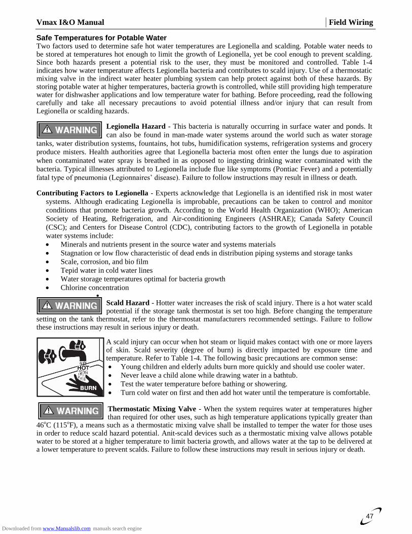
Vmax I&O Manual │Field Wiring
47
Safe Temperatures for Potable Water Two factors used to determine safe hot water temperatures are Legionella and scalding. Potable water needs to be stored at temperatures hot enough to limit the growth of Legionella, yet be cool enough to prevent scalding. Since both hazards present a potential risk to the user, they must be monitored and controlled. Table 1-4 indicates how water temperature affects Legionella bacteria and contributes to scald injury. Use of a thermostatic mixing valve in the indirect water heater plumbing system can help protect against both of these hazards. By storing potable water at higher temperatures, bacteria growth is controlled, while still providing high temperature water for dishwasher applications and low temperature water for bathing. Before proceeding, read the following carefully and take all necessary precautions to avoid potential illness and/or injury that can result from Legionella or scalding hazards.
Legionella Hazard - This bacteria is naturally occurring in surface water and ponds. It
can also be found in man-made water systems around the world such as water storage
tanks, water distribution systems, fountains, hot tubs, humidification systems, refrigeration systems and grocery
produce misters. Health authorities agree that Legionella bacteria most often enter the lungs due to aspiration
when contaminated water spray is breathed in as opposed to ingesting drinking water contaminated with the
bacteria. Typical illnesses attributed to Legionella include flue like symptoms (Pontiac Fever) and a potentially
fatal type of pneumonia (Legionnaires’ disease). Failure to follow instructions may result in illness or death.
Contributing Factors to Legionella - Experts acknowledge that Legionella is an identified risk in most water
systems. Although eradicating Legionella is improbable, precautions can be taken to control and monitor
conditions that promote bacteria growth. According to the World Health Organization (WHO); American
Society of Heating, Refrigeration, and Air-conditioning Engineers (ASHRAE); Canada Safety Council
(CSC); and Centers for Disease Control (CDC), contributing factors to the growth of Legionella in potable
water systems include:
Minerals and nutrients present in the source water and systems materials
Stagnation or low flow characteristic of dead ends in distribution piping systems and storage tanks
Scale, corrosion, and bio film
Tepid water in cold water lines
Water storage temperatures optimal for bacteria growth
Chlorine concentration
Scald Hazard - Hotter water increases the risk of scald injury. There is a hot water scald potential if the storage tank thermostat is set too high. Before changing the temperature
setting on the tank thermostat, refer to the thermostat manufacturers recommended settings. Failure to follow these instructions may result in serious injury or death.
A scald injury can occur when hot steam or liquid makes contact with one or more layers of skin. Scald severity (degree of burn) is directly impacted by exposure time and temperature. Refer to Table 1-4. The following basic precautions are common sense:
Young children and elderly adults burn more quickly and should use cooler water.
Never leave a child alone while drawing water in a bathtub.
Test the water temperature before bathing or showering.
Turn cold water on first and then add hot water until the temperature is comfortable. Thermostatic Mixing Valve - When the system requires water at temperatures higher than required for other uses, such as high temperature applications typically greater than
46oC (115
oF), a means such as a thermostatic mixing valve shall be installed to temper the water for those uses
in order to reduce scald hazard potential. Anit-scald devices such as a thermostatic mixing valve allows potable water to be stored at a higher temperature to limit bacteria growth, and allows water at the tap to be delivered at a lower temperature to prevent scalds. Failure to follow these instructions may result in serious injury or death.
Downloaded from www.Manualslib.com manuals search engine
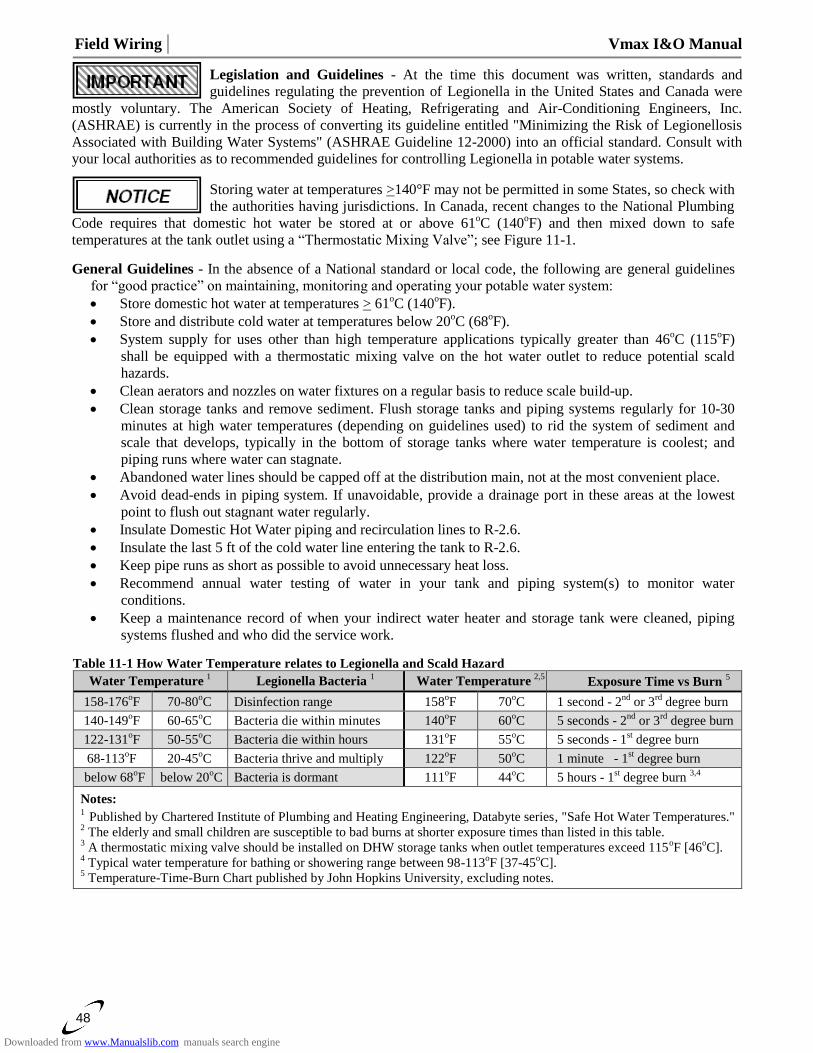
Field Wiring │ Vmax I&O Manual
48
Legislation and Guidelines - At the time this document was written, standards and
guidelines regulating the prevention of Legionella in the United States and Canada were
mostly voluntary. The American Society of Heating, Refrigerating and Air-Conditioning Engineers, Inc.
(ASHRAE) is currently in the process of converting its guideline entitled "Minimizing the Risk of Legionellosis
Associated with Building Water Systems" (ASHRAE Guideline 12-2000) into an official standard. Consult with
your local authorities as to recommended guidelines for controlling Legionella in potable water systems.
Storing water at temperatures >140°F may not be permitted in some States, so check with
the authorities having jurisdictions. In Canada, recent changes to the National Plumbing
Code requires that domestic hot water be stored at or above 61oC (140
oF) and then mixed down to safe
temperatures at the tank outlet using a “Thermostatic Mixing Valve”; see Figure 11-1.
General Guidelines - In the absence of a National standard or local code, the following are general guidelines
for “good practice” on maintaining, monitoring and operating your potable water system:
Store domestic hot water at temperatures > 61oC (140
oF).
Store and distribute cold water at temperatures below 20oC (68
oF).
System supply for uses other than high temperature applications typically greater than 46oC (115
oF)
shall be equipped with a thermostatic mixing valve on the hot water outlet to reduce potential scald
hazards.
Clean aerators and nozzles on water fixtures on a regular basis to reduce scale build-up.
Clean storage tanks and remove sediment. Flush storage tanks and piping systems regularly for 10-30
minutes at high water temperatures (depending on guidelines used) to rid the system of sediment and
scale that develops, typically in the bottom of storage tanks where water temperature is coolest; and
piping runs where water can stagnate.
Abandoned water lines should be capped off at the distribution main, not at the most convenient place.
Avoid dead-ends in piping system. If unavoidable, provide a drainage port in these areas at the lowest
point to flush out stagnant water regularly.
Insulate Domestic Hot Water piping and recirculation lines to R-2.6.
Insulate the last 5 ft of the cold water line entering the tank to R-2.6.
Keep pipe runs as short as possible to avoid unnecessary heat loss.
Recommend annual water testing of water in your tank and piping system(s) to monitor water
conditions.
Keep a maintenance record of when your indirect water heater and storage tank were cleaned, piping
systems flushed and who did the service work.
Table 11-1 How Water Temperature relates to Legionella and Scald Hazard
Water Temperature 1 Legionella Bacteria
1 Water Temperature
2,5 Exposure Time vs Burn
5
158-176oF 70-80
oC Disinfection range 158
oF 70
oC 1 second - 2
nd or 3
rd degree burn
140-149oF 60-65
oC Bacteria die within minutes 140
oF 60
oC 5 seconds - 2
nd or 3
rd degree burn
122-131oF 50-55
oC Bacteria die within hours 131
oF 55
oC 5 seconds - 1
st degree burn
68-113oF 20-45
oC Bacteria thrive and multiply 122
oF 50
oC 1 minute - 1
st degree burn
below 68oF below 20
oC Bacteria is dormant 111
oF 44
oC 5 hours - 1
st degree burn
3,4
Notes: 1
Published by Chartered Institute of Plumbing and Heating Engineering, Databyte series, "Safe Hot Water Temperatures." 2 The elderly and small children are susceptible to bad burns at shorter exposure times than listed in this table.
3 A thermostatic mixing valve should be installed on DHW storage tanks when outlet temperatures exceed 115
oF [46
oC].
4 Typical water temperature for bathing or showering range between 98-113
oF [37-45
oC].
5 Temperature-Time-Burn Chart published by John Hopkins University, excluding notes.
Downloaded from www.Manualslib.com manuals search engine
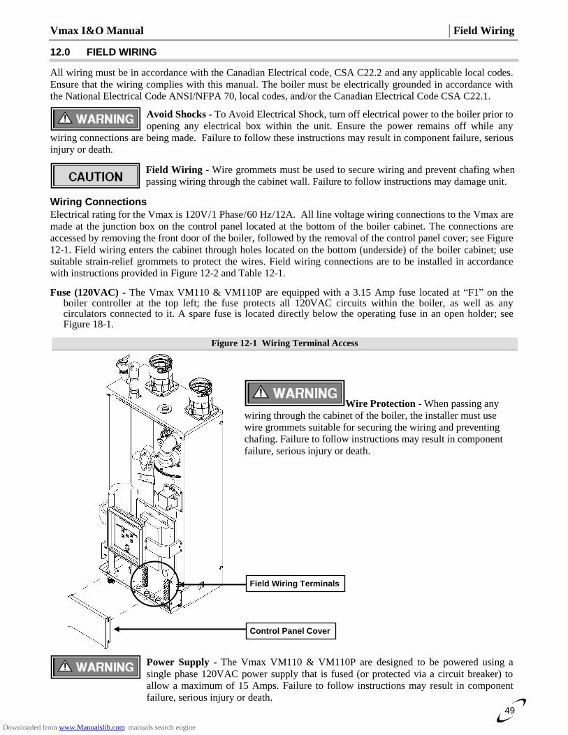
Vmax I&O Manual │Field Wiring
49
12.0 FIELD WIRING
All wiring must be in accordance with the Canadian Electrical code, CSA C22.2 and any applicable local codes.
Ensure that the wiring complies with this manual. The boiler must be electrically grounded in accordance with
the National Electrical Code ANSI/NFPA 70, local codes, and/or the Canadian Electrical Code CSA C22.1.
Avoid Shocks - To Avoid Electrical Shock, turn off electrical power to the boiler prior to
opening any electrical box within the unit. Ensure the power remains off while any
wiring connections are being made. Failure to follow these instructions may result in component failure, serious
injury or death.
Field Wiring - Wire grommets must be used to secure wiring and prevent chafing when
passing wiring through the cabinet wall. Failure to follow instructions may damage unit.
Wiring Connections
Electrical rating for the Vmax is 120V / 1 Phase / 60 Hz / 12A. All line voltage wiring connections to the Vmax are
made at the junction box on the control panel located at the bottom of the boiler cabinet. The connections are
accessed by removing the front door of the boiler, followed by the removal of the control panel cover; see Figure
12-1. Field wiring enters the cabinet through holes located on the bottom (underside) of the boiler cabinet; use
suitable strain-relief grommets to protect the wires. Field wiring connections are to be installed in accordance
with instructions provided in Figure 12-2 and Table 12-1.
Fuse (120VAC) - The Vmax VM110 & VM110P are equipped with a 3.15 Amp fuse located at “F1” on the boiler controller at the top left; the fuse protects all 120VAC circuits within the boiler, as well as any circulators connected to it. A spare fuse is located directly below the operating fuse in an open holder; see Figure 18-1.
Figure 12-1 Wiring Terminal Access
Power Supply - The Vmax VM110 & VM110P are designed to be powered using a
single phase 120VAC power supply that is fused (or protected via a circuit breaker) to
allow a maximum of 15 Amps. Failure to follow instructions may result in component
failure, serious injury or death.
Field Wiring Terminals
Control Panel Cover
Wire Protection - When passing any
wiring through the cabinet of the boiler, the installer must use
wire grommets suitable for securing the wiring and preventing
chafing. Failure to follow instructions may result in component
failure, serious injury or death.
Downloaded from www.Manualslib.com manuals search engine
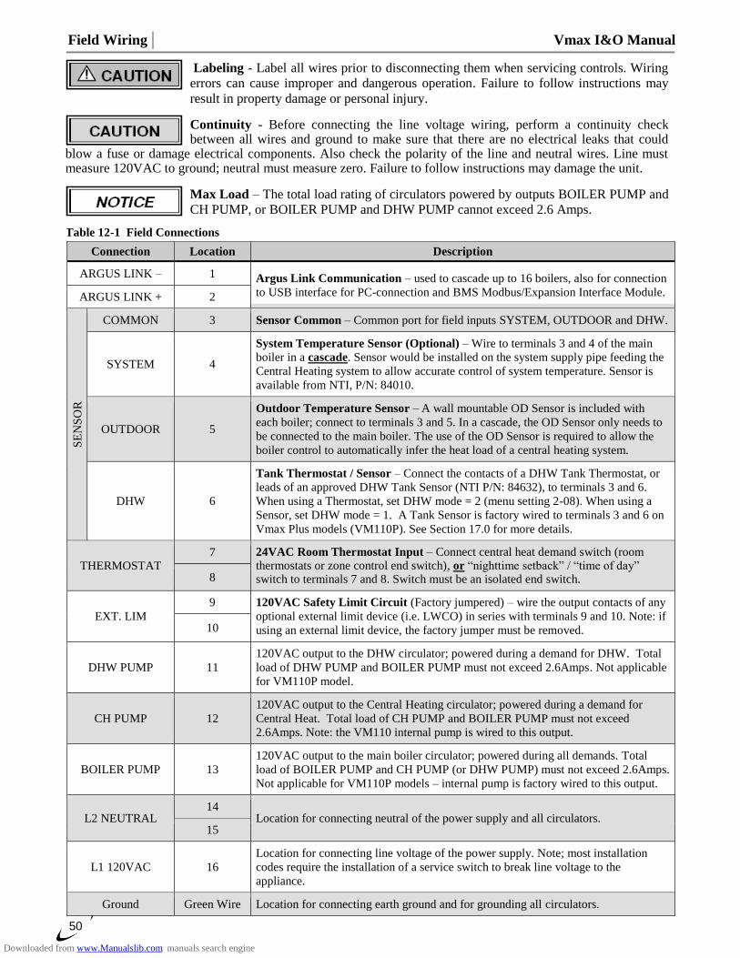
Field Wiring │ Vmax I&O Manual
50
Labeling - Label all wires prior to disconnecting them when servicing controls. Wiring
errors can cause improper and dangerous operation. Failure to follow instructions may
result in property damage or personal injury.
Continuity - Before connecting the line voltage wiring, perform a continuity check between all wires and ground to make sure that there are no electrical leaks that could
blow a fuse or damage electrical components. Also check the polarity of the line and neutral wires. Line must measure 120VAC to ground; neutral must measure zero. Failure to follow instructions may damage the unit.
Max Load – The total load rating of circulators powered by outputs BOILER PUMP and
CH PUMP, or BOILER PUMP and DHW PUMP cannot exceed 2.6 Amps.
Table 12-1 Field Connections
Connection Location Description
ARGUS LINK – 1 Argus Link Communication – used to cascade up to 16 boilers, also for connection
to USB interface for PC-connection and BMS Modbus/Expansion Interface Module. ARGUS LINK + 2
SE
NS
OR
COMMON 3 Sensor Common – Common port for field inputs SYSTEM, OUTDOOR and DHW.
SYSTEM 4
System Temperature Sensor (Optional) – Wire to terminals 3 and 4 of the main
boiler in a cascade. Sensor would be installed on the system supply pipe feeding the
Central Heating system to allow accurate control of system temperature. Sensor is
available from NTI, P/N: 84010.
OUTDOOR 5
Outdoor Temperature Sensor – A wall mountable OD Sensor is included with
each boiler; connect to terminals 3 and 5. In a cascade, the OD Sensor only needs to
be connected to the main boiler. The use of the OD Sensor is required to allow the
boiler control to automatically infer the heat load of a central heating system.
DHW 6
Tank Thermostat / Sensor – Connect the contacts of a DHW Tank Thermostat, or
leads of an approved DHW Tank Sensor (NTI P/N: 84632), to terminals 3 and 6.
When using a Thermostat, set DHW mode = 2 (menu setting 2-08). When using a
Sensor, set DHW mode = 1. A Tank Sensor is factory wired to terminals 3 and 6 on
Vmax Plus models (VM110P). See Section 17.0 for more details.
THERMOSTAT 7 24VAC Room Thermostat Input – Connect central heat demand switch (room
thermostats or zone control end switch), or “nighttime setback” / “time of day” switch to terminals 7 and 8. Switch must be an isolated end switch. 8
EXT. LIM
9 120VAC Safety Limit Circuit (Factory jumpered) – wire the output contacts of any
optional external limit device (i.e. LWCO) in series with terminals 9 and 10. Note: if
using an external limit device, the factory jumper must be removed. 10
DHW PUMP 11
120VAC output to the DHW circulator; powered during a demand for DHW. Total
load of DHW PUMP and BOILER PUMP must not exceed 2.6Amps. Not applicable
for VM110P model.
CH PUMP 12
120VAC output to the Central Heating circulator; powered during a demand for
Central Heat. Total load of CH PUMP and BOILER PUMP must not exceed
2.6Amps. Note: the VM110 internal pump is wired to this output.
BOILER PUMP 13
120VAC output to the main boiler circulator; powered during all demands. Total
load of BOILER PUMP and CH PUMP (or DHW PUMP) must not exceed 2.6Amps.
Not applicable for VM110P models – internal pump is factory wired to this output.
L2 NEUTRAL 14
Location for connecting neutral of the power supply and all circulators. 15
L1 120VAC 16
Location for connecting line voltage of the power supply. Note; most installation
codes require the installation of a service switch to break line voltage to the
appliance.
Ground Green Wire Location for connecting earth ground and for grounding all circulators.
Downloaded from www.Manualslib.com manuals search engine
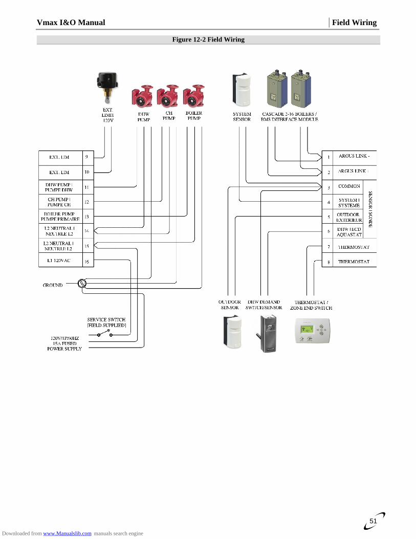
Vmax I&O Manual │Field Wiring
51
Figure 12-2 Field Wiring
Downloaded from www.Manualslib.com manuals search engine
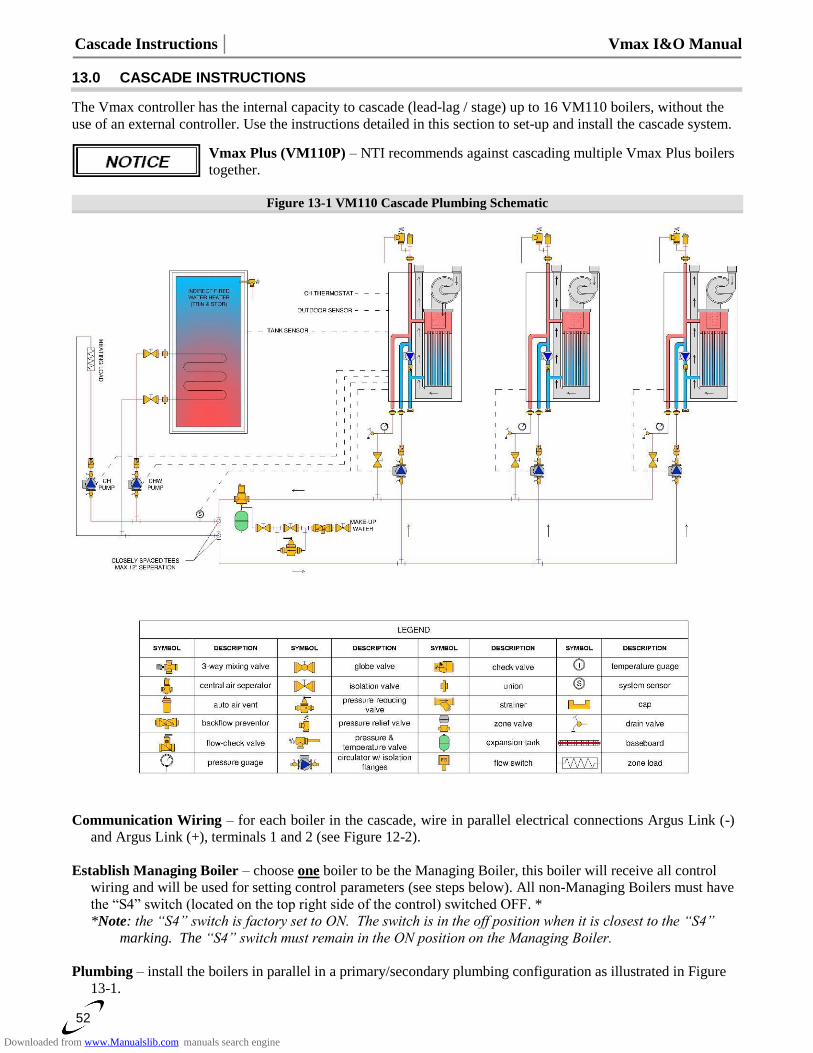
Cascade Instructions │ Vmax I&O Manual
52
13.0 CASCADE INSTRUCTIONS
The Vmax controller has the internal capacity to cascade (lead-lag / stage) up to 16 VM110 boilers, without the
use of an external controller. Use the instructions detailed in this section to set-up and install the cascade system.
Vmax Plus (VM110P) – NTI recommends against cascading multiple Vmax Plus boilers
together.
Figure 13-1 VM110 Cascade Plumbing Schematic
Communication Wiring – for each boiler in the cascade, wire in parallel electrical connections Argus Link (-)
and Argus Link (+), terminals 1 and 2 (see Figure 12-2).
Establish Managing Boiler – choose one boiler to be the Managing Boiler, this boiler will receive all control
wiring and will be used for setting control parameters (see steps below). All non-Managing Boilers must have
the “S4” switch (located on the top right side of the control) switched OFF. *
*Note: the “S4” switch is factory set to ON. The switch is in the off position when it is closest to the “S4”
marking. The “S4” switch must remain in the ON position on the Managing Boiler.
Plumbing – install the boilers in parallel in a primary/secondary plumbing configuration as illustrated in Figure
13-1.
Downloaded from www.Manualslib.com manuals search engine
Vmax I&O Manual │Cascade Instructions
53
System Sensor – install a system sensor (NTI P/N: 84010) on the outlet (supply) pipe feeding the heating system,
see Figure 13-1. ire the system sensor to terminals 3 and 4 of the Managing Boiler (left boiler in illustration).
IMPORTANT: the use of the system sensor is mandatory for proper operation of the boiler cascade system.
Outdoor Sensor – when using an outdoor sensor it must be connected to terminals 3 and 5 of the Managing
boiler (left boiler in illustration); outdoor sensors connected to non-Managing boilers will be ignored.
Boiler Pump – each boiler in the cascade must have its own circulator (see Figure 13-1) which is operated by
each respective boiler, via the BOILER PUMP output (terminal 13). The VM110 internal circulator, which is
factory wired to the CH PUMP output, must be rewired to the BOILER PUMP output for the boiler to operate
properly as part of a cascade.
CH Pump – the Managing Boiler can control the Central Heating Pump via its CH PUMP output (terminal 12).
IMPORTANT: due to the limited switching capacity of the CH PUMP output, it may be necessary to use an
isolation relay to activate the CH Pump, see Table 12-1.
DHW Pump – the Managing Boiler can control the DHW Pump via its DHW PUMP output (terminal 11).
IMPORTANT: due to the limited switching capacity of the DHW PUMP output, it may be necessary to use
an isolation relay to activate the DHW Pump, see Table 12-1.
Central Heat Demand Switch (Room Thermostat) – connect to terminals 7 and 8 (T, T) of the Managing
Boiler. Switch must be an isolated end switch (dry contact). Central Heat settings are programed from the
Managing Boiler only, i.e. Installer menu settings 2-01, 2-02, 2-03, 2-04, 2-05 and 2-06.
Tank Thermostat / Sensor – connect to terminals 3 and 6 of the Managing Boiler. DHW settings are programed
from the Managing Boiler only, i.e. Installer menu settings 2-07, 2-08 and 2-09. Set DHW Mode (Installer
menu setting 2-08) according to device used; Thermostat = 2, Sensor = 1.
Boiler Address – assign a unique boiler address for each boiler in the cascade via Installer menu setting 2-20.
Managing boiler must be set = 1; other boilers must be set from 2 to 16.
Rotation Interval – establishes the time, in days, between advancements of the staging sequence of boilers in the
cascade; set via Installer menu setting 2-22 of the Managing Boiler.
Emergency Setpoint – establishes an emergency (back-up) boiler operating setpoint in the event communication
is lost between boilers, or if the system sensor is not connected. Set via Installer menu setting 2-21 of each
boiler in the cascade.
Downloaded from www.Manualslib.com manuals search engine
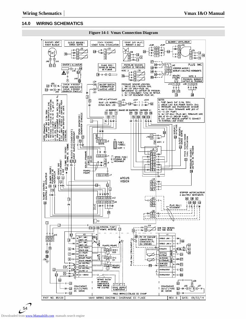
Wiring Schematics │ Vmax I&O Manual
54
14.0 WIRING SCHEMATICS
Figure 14-1 Vmax Connection Diagram
Downloaded from www.Manualslib.com manuals search engine
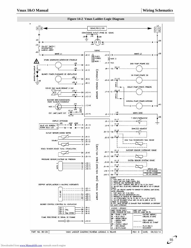
Vmax I&O Manual │Wiring Schematics
55
Figure 14-2 Vmax Ladder-Logic Diagram
Downloaded from www.Manualslib.com manuals search engine
Wiring Schematics │ Vmax I&O Manual
56
15.0 INSTALLATION CHECKLIST
Installation
1. If operating on Propane Gas, convert boiler using appropriate conversion orifice. See Table 7-1. 2. Locate the boiler in accordance with Section 3.0 of this manual. 3. Install the Vent/Air-inlet piping in accordance with Sections 4.0 and 5.0 of this manual. Ensure all joints are secured and cemented properly. Both the Vent and Air-inlet pipes must terminate outdoors. Perform the Mandatory Pre-commissioning Procedure for Plastic Venting in Section 4.0. 4. Connect the condensate trap and drain in accordance with Section 6.0 of this manual. 5. Connect the gas supply in accordance with Section 7.0 of this manual. 6. Install the plumbing in accordance with this manual. Flush/cleanse the internals of the heating system. Treat system water with Fernox F1 Protector when needed. 7. Connect field wiring in accordance with Section 12.0 of this manual. 8. Advise home/building owner of their responsibilities with respect to maintaining the boiler.
The building owner is responsible for keeping the Vent/Air-inlet termination free of snow,
ice, or other potential blockages and for scheduling boiler routine maintenance as
described in the next section. Failure to properly maintain the boiler may result in serious injury or death.
Start-up
Allow primers/cements to cure for 8 hours prior to Start-up. If curing time is less than 8
hours, first perform Steps 2 through 6 of Mandatory Pre-commissioning Procedure for
Plastic Venting in Section 4.0. Failure to follow these instructions can result in explosion, serious injury or death.
1. Turn gas shut-off valve to the ON position. 2. Turn Power on to the boiler. 3. Set Controller to the desired settings. 4. Turn thermostat up, Ignition will occur.
Operational Checklist
1. System is free of gas leaks. 2. System is free of water leaks. 3. Water pressure is maintained above 15 PSI. 4. All air is purged from the heating system piping. 5. Ensure proper water flow rate; unit must not kettle, bang, hiss or flash the water to steam. 6. Ensure gas line pressure is in accordance with Section 9.0. 7. System is free of combustion leaks. 8. Unit must operate smoothly. 9. Ensure the flue gas combustion readings are within the tolerances listed in Table 9-1. 10. Each ignition must be smooth. 11. Verify that all condensate lines are clean and drain freely.
Before Leaving
1. Remove line pressure gauge from gas valve, tighten bleed screw, test screw for leaks. See Section 9.0. 2. Install plug into the flue gas test port and test for leaks, see Section 9.0. 3. Allow the boiler to complete at least one heating cycle, or to operate for at least 15 minutes. 4. Always verify proper operation after servicing.
Instructions to Installing Contractor
1. Ensure that the customer receives the Warranty Documentation included with the installation manual. 2. Leave the manual with the customer so they know when to call for annual maintenance and inspection.
This boiler must have water flowing through it whenever the burner is firing. Failure to
comply may damage the unit, void the warranty, and cause serious injury or death.
Allowing the boiler to operate with a dirty combustion chamber will adversely affect its
operation and void the warranty. Failure to clean the heat exchanger on a frequency that
matches the need of the application may result in fire, property damage, or death.
Downloaded from www.Manualslib.com manuals search engine