Embed Size (px)
Citation preview
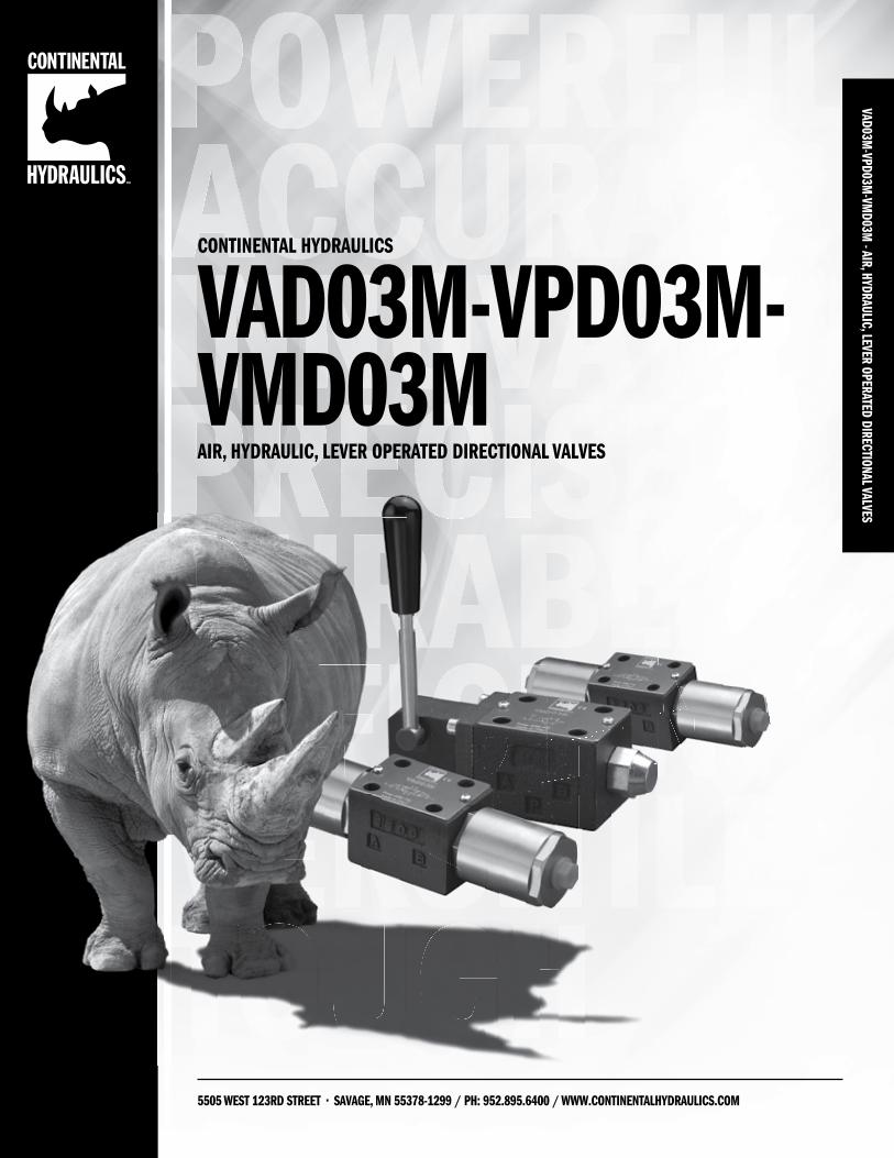
VAD03M-VPD03M
-VMD03M
- AIR, HYDRAULIC, LEVER OPERATED DIRECTIONAL VALVES
5505 WEST 123RD STREET • SAVAGE, MN 55378-1299 / PH: 952.895.6400 / WWW.CONTINENTALHYDRAULICS.COM
CONTINENTAL HYDRAULICS
VAD03M-VPD03M-VMD03M AIR, HYDRAULIC, LEVER OPERATED DIRECTIONAL VALVES
2 WWW.CONTINENTALHYDRAULICS.COM - [email protected]
PRECISEVA
D03M
-VPD
03M
-VM
D03M
- AI
R, H
YDRA
ULIC
, LEV
ER O
PERA
TED
DIRE
CTIO
NAL V
ALVE
S VAD03M-VPD03M-VMD03MAIR, HYDRAULIC, LEVER OPERATED DIRECTIONAL VALVES
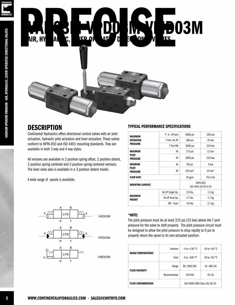
DESCRIPTIONContinental Hydraulics offers directional control valves with air pilot actuation, hydraulic pilot actuation and lever actuation. These valves conform to NFPA D03 and ISO 4401 mounting standards. They are available in both 3 way and 4 way styles.
All versions are available in 2 position spring offset, 2 position detent, 2 position spring centered and 3 position spring centered versions. The lever valve also is available in a 3 position detent model.
A wide range of spools is available.
*NOTE: The pilot pressure must be at least 215 psi (15 bar) above the T port pressure for the valve to shift properly. The pilot pressure circuit must be designed to allow the pilot pressure to drop rapidly to 0 psi to properly return the spool to its non-actuated position.
TYPICAL PERFORMANCE SPECIFICATIONS
MAXIMUM OPERATINGPRESSURE
P - A - B Ports 5000 psi 350 bar
T Port VA, VP 360 psi 25 bar
T Port VM 3000 psi 210 bar
MAXIMUMPILOT PRESSURE
VA 175 psi 12 bar
VP 3000 psi 210 bar
MINIMUMPILOTPRESSURE
VA 60 psi 4 bar
VP 215 psi* 15 bar*
FLOW RATE 20 gpm 76 l/min
MOUNTING SURFACENFPA D03
ISO 4401-03-02-0-03
MAXIMUMWEIGHT
VA, VP Single Op. 2.9 lbs 1.3 kg
VA, VP Dual Op. 3.7 lbs 1.7 kg
VM - Lever 4.6 lbs 2.1 kg
RANGE TEMPERATURESAmbient - 4 to +130 °F -20 to +54 °C
Fluid - 4 to +180 °F -20 to +82 °C
FLUID VISCOSITYRange 60 -1900 SUS 10 - 400 cSt
Recommended 120 SUS 25 cSt
FLUID CONTAMINATION ISO 4406:1999 Class 20/18/15
[email protected] - WWW.CONTINENTALHYDRAULICS.COM 3
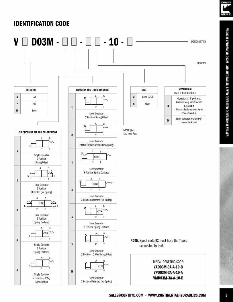
SEAL
A Buna (STD)
G Viton
MECHANICALOMIT IF NOT REQUIRED
R
Operator at ‘B’ port end. Available only with function
1, 5 and 9. Also available on lever valve
codes 3 and 4.
90Lever operator rotated 90°
toward tank port.
V D03M - - - 10 -
TYPICAL ORDERING CODE:
VAD03M-3A-A-10-B VPD03M-3A-A-10-A VMD03M-3A-A-10-B
IDENTIFICATION CODE
DESIGN LETTER
OPERATOR
A Air
P Oil
M Lever
Operator
Spool TypeSee Next Page
VAD03M-VPD03M
-VMD03M
- AIR, HYDRAULIC, LEVER OPERATED DIRECTIONAL VALVESFUNCTION FOR AIR AND OIL OPERATOR
1
Single Operator 2 Position
Spring Offset
2
Dual Operator 2 Position
Detented (No Spring)
3
Dual Operator 3 Position
Spring Centered
5
Single Operator 2 Position
Spring Centered
9
Single Operator 2 Position - 3 Way
Spring Offset
FUNCTION FOR LEVER OPERATOR
1
Lever Operator 2 Position Spring Offset
2
Lever Operator 2 Offset Position Detented (No Spring)
3
Lever Operator 3 Position Spring Centered
4
Lever Operator 3 Position Detented (No Spring)
5
Lever Operator 2 Position Spring Centered
9
Lever Operator 2 Position - 3 Way Spring Offset
25
Lever Operator 2 Position Detented (No Spring)
NOTE: Spool code 9X must have the T port connected to tank.
4 WWW.CONTINENTALHYDRAULICS.COM - [email protected]
VAD0
3M-V
PD03
M-V
MD0
3M -
AIR,
HYD
RAUL
IC, L
EVER
OPE
RATE
D DI
RECT
IONA
L VAL
VES
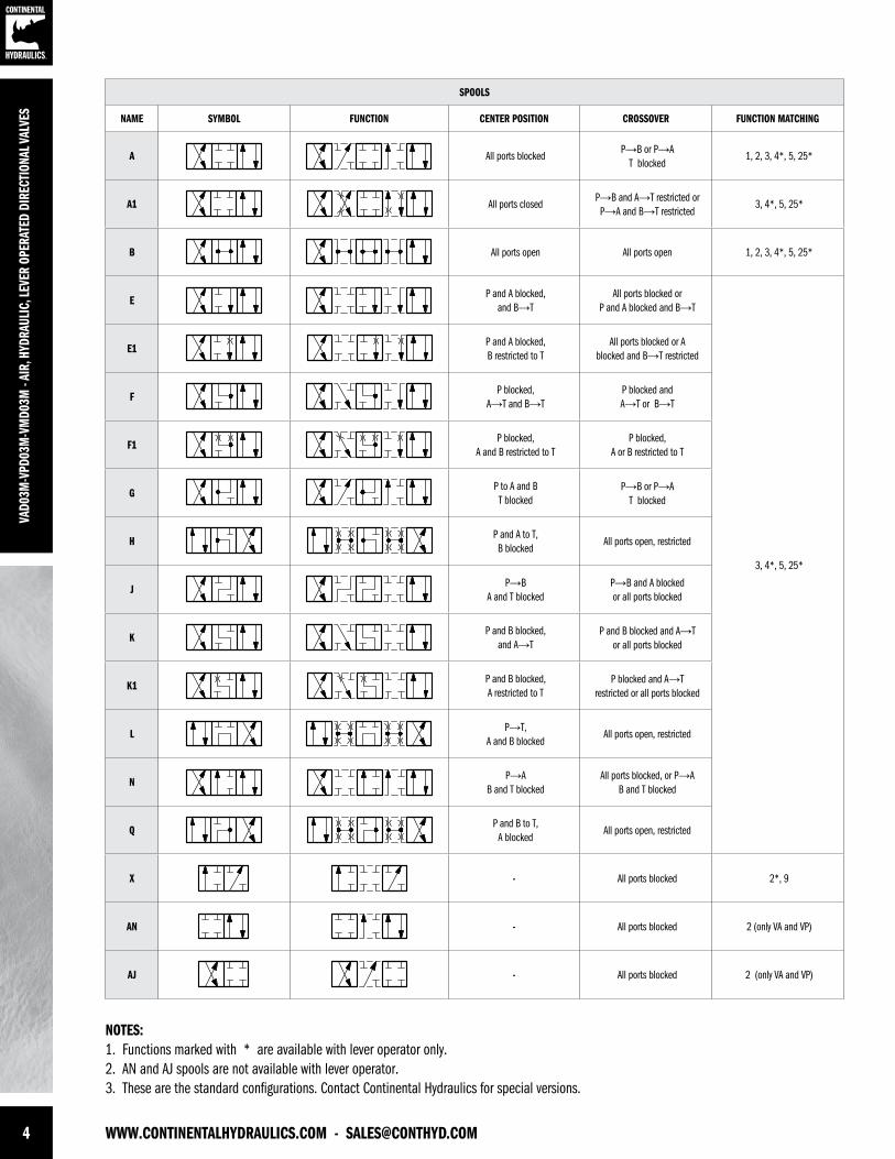
SPOOLS
NAME SYMBOL FUNCTION CENTER POSITION CROSSOVER FUNCTION MATCHING
A All ports blockedP→B or P→A
T blocked1, 2, 3, 4*, 5, 25*
A1 All ports closedP→B and A→T restricted or P→A and B→T restricted
3, 4*, 5, 25*
B All ports open All ports open 1, 2, 3, 4*, 5, 25*
EP and A blocked,
and B→TAll ports blocked or
P and A blocked and B→T
3, 4*, 5, 25*
E1P and A blocked, B restricted to T
All ports blocked or Ablocked and B→T restricted
FP blocked,
A→T and B→TP blocked and A→T or B→T
F1P blocked,
A and B restricted to TP blocked,
A or B restricted to T
GP to A and B T blocked
P→B or P→A T blocked
HP and A to T,B blocked
All ports open, restricted
JP→B
A and T blockedP→B and A blocked or all ports blocked
KP and B blocked,
and A→TP and B blocked and A→T
or all ports blocked
K1P and B blocked, A restricted to T
P blocked and A→Trestricted or all ports blocked
LP→T,
A and B blockedAll ports open, restricted
NP→A
B and T blockedAll ports blocked, or P→A
B and T blocked
QP and B to T,
A blockedAll ports open, restricted
X - All ports blocked 2*, 9
AN - All ports blocked 2 (only VA and VP)
AJ - All ports blocked 2 (only VA and VP)
NOTES:1. Functions marked with * are available with lever operator only. 2. AN and AJ spools are not available with lever operator.3. These are the standard configurations. Contact Continental Hydraulics for special versions.
[email protected] - WWW.CONTINENTALHYDRAULICS.COM 5
VAD03M-VPD03M
-VMD03M
- AIR, HYDRAULIC, LEVER OPERATED DIRECTIONAL VALVES
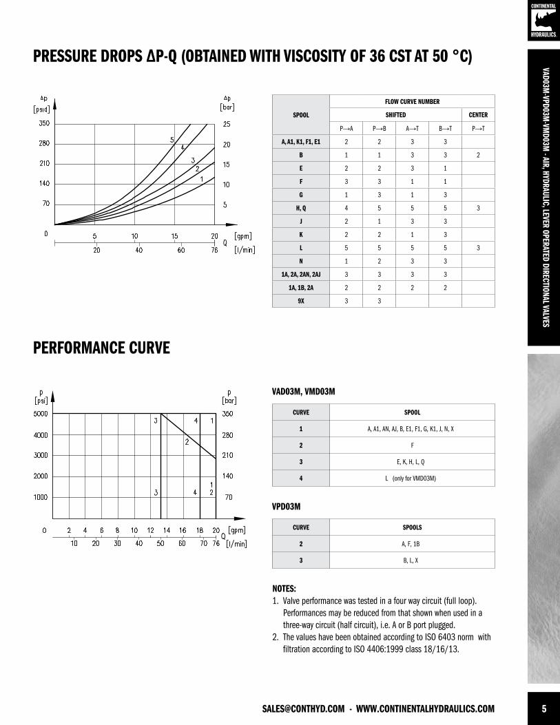
NOTES:1. Valve performance was tested in a four way circuit (full loop). Performances may be reduced from that shown when used in a three-way circuit (half circuit), i.e. A or B port plugged.2. The values have been obtained according to ISO 6403 norm with filtration according to ISO 4406:1999 class 18/16/13.
PRESSURE DROPS ∆P-Q (OBTAINED WITH VISCOSITY OF 36 CST AT 50 °C)
PERFORMANCE CURVE
VAD03M, VMD03M
VPD03M
SPOOL
FLOW CURVE NUMBER
SHIFTED CENTER
P→A P→B A→T B→T P→T
A, A1, K1, F1, E1 2 2 3 3
B 1 1 3 3 2
E 2 2 3 1
F 3 3 1 1
G 1 3 1 3
H, Q 4 5 5 5 3
J 2 1 3 3
K 2 2 1 3
L 5 5 5 5 3
N 1 2 3 3
1A, 2A, 2AN, 2AJ 3 3 3 3
1A, 1B, 2A 2 2 2 2
9X 3 3
CURVE SPOOL
1 A, A1, AN, AJ, B, E1, F1, G, k1, J, N, X
2 F
3 E, k, H, L, Q
4 L (only for VMD03M)
CURVE SPOOLS
2 A, F, 1B
3 B, L, X
6 WWW.CONTINENTALHYDRAULICS.COM - [email protected]
VAD0
3M-V
PD03
M-V
MD0
3M -
AIR,
HYD
RAUL
IC, L
EVER
OPE
RATE
D DI
RECT
IONA
L VAL
VES
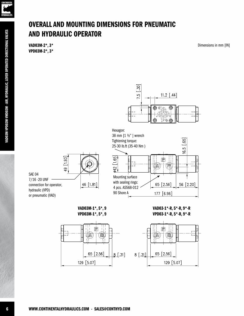
VAD03M-1*, 5*, 9VPD03M-1*, 5*, 9
VAD03-1*-R, 5*-R, 9*-RVPD03-1*-R, 5*-R, 9*-R
SAE 047/16 -20 UNF connection for operator,hydraulic (VPD) or pneumatic (VAD)
Hexagon: 38 mm [1 ½” ] wrench Tightening torque: 25-30 lb.ft (35-40 Nm )
OVERALL AND MOUNTING DIMENSIONS FOR PNEUMATICAND HYDRAULIC OPERATOR
Dimensions in mm [IN]VAD03M-2*, 3*VPD03M-2*, 3*
Mounting surface with sealing rings:4 pcs. AS568-012 90 Shore A
[email protected] - WWW.CONTINENTALHYDRAULICS.COM 7
VAD03M-VPD03M
-VMD03M
- AIR, HYDRAULIC, LEVER OPERATED DIRECTIONAL VALVES
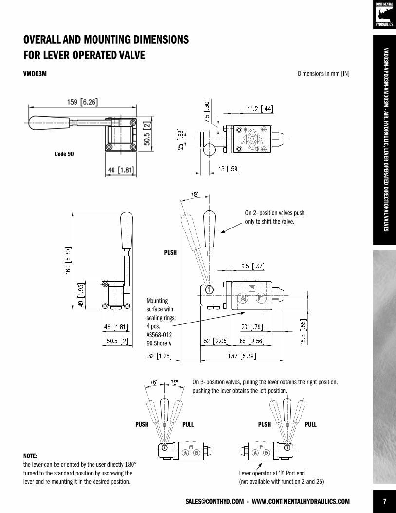
On 2- position valves push only to shift the valve.
On 3- position valves, pulling the lever obtains the right position, pushing the lever obtains the left position.
Mounting surface with sealing rings:4 pcs. AS568-012 90 Shore A
NOTE:the lever can be oriented by the user directly 180° turned to the standard position by uscrewing the lever and re-mounting it in the desired position.
PUSH
PUSH
PUSH
Lever operator at ‘B’ Port end (not available with function 2 and 25)
PULL PULL
OVERALL AND MOUNTING DIMENSIONSFOR LEVER OPERATED VALVE
Dimensions in mm [IN]VMD03M
Code 90
8 WWW.CONTINENTALHYDRAULICS.COM - [email protected]
VAD0
3M-V
PD03
M-V
MD0
3M -
AIR,
HYD
RAUL
IC, L
EVER
OPE
RATE
D DI
RECT
IONA
L VAL
VES
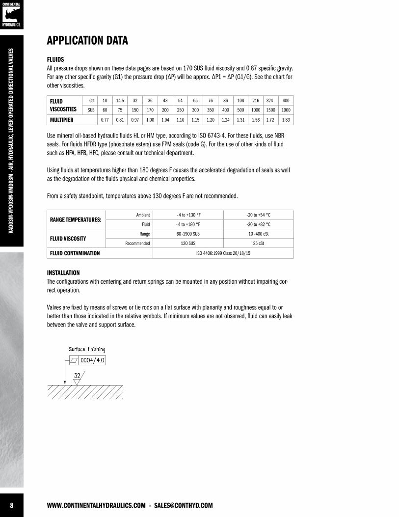
APPLICATION DATAFLUIDSAll pressure drops shown on these data pages are based on 170 SUS fluid viscosity and 0.87 specific gravity. For any other specific gravity (G1) the pressure drop (∆P) will be approx. ∆P1 = ∆P (G1/G). See the chart for other viscosities.
Use mineral oil-based hydraulic fluids HL or HM type, according to ISO 6743-4. For these fluids, use NBR seals. For fluids HFDR type (phosphate esters) use FPM seals (code G). For the use of other kinds of fluid such as HFA, HFB, HFC, please consult our technical department.
Using fluids at temperatures higher than 180 degrees F causes the accelerated degradation of seals as well as the degradation of the fluids physical and chemical properties.
From a safety standpoint, temperatures above 130 degrees F are not recommended.
FLUIDVISCOSITIES
Cst 10 14.5 32 36 43 54 65 76 86 108 216 324 400
SUS 60 75 150 170 200 250 300 350 400 500 1000 1500 1900
MULTIPIER 0.77 0.81 0.97 1.00 1.04 1.10 1.15 1.20 1.24 1.31 1.56 1.72 1.83
INSTALLATIONThe configurations with centering and return springs can be mounted in any position without impairing cor-rect operation.
Valves are fixed by means of screws or tie rods on a flat surface with planarity and roughness equal to or better than those indicated in the relative symbols. If minimum values are not observed, fluid can easily leak between the valve and support surface.
RANGE TEMPERATURES: Ambient - 4 to +130 °F -20 to +54 °C
Fluid - 4 to +180 °F -20 to +82 °C
FLUID VISCOSITYRange 60 -1900 SUS 10 - 400 cSt
Recommended 120 SUS 25 cSt
FLUID CONTAMINATION ISO 4406:1999 Class 20/18/15
[email protected] - WWW.CONTINENTALHYDRAULICS.COM 9
VAD03M-VPD03M
-VMD03M
- AIR, HYDRAULIC, LEVER OPERATED DIRECTIONAL VALVES
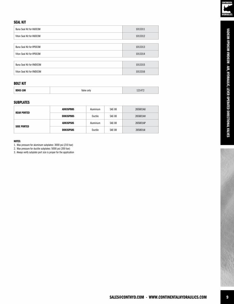
SUBPLATES
SEAL KIT
BOLT KIT
Buna Seal kit for VAD03M 1013311
Viton Seal kit for VAD03M 1013312
BD03-100 Valve only 121472
Buna Seal kit for VPD03M 1013313
Viton Seal kit for VPD03M 1013314
Buna Seal kit for VMD03M 1013315
Viton Seal kit for VMD03M 1013316
REAR PORTEDAD03SPB8S Aluminium SAE-08 265801AU
DD03SPB8S Ductile SAE-08 265801AH
SIDE PORTEDAD03SPS8S Aluminium SAE-08 265801AP
DD03SPS8S Ductile SAE-08 265801AI
NOTES:1. Max pressure for aluminum subplates: 3000 psi (210 bar) 2. Max pressure for ductile subplates: 5000 psi (350 bar)3. Always verify subplate port size is proper for the application
VAD0
3M-V
PD03
M-V
MD0
3M -
AIR,
HYD
RAUL
IC, L
EVER
OPE
RATE
D DI
RECT
IONA
L VAL
VES
FORM NO. 1013296. REV. 12/2011. © 2011 CONTINENTAL HYDRAULICS. ALL RIGHTS RESERVED. PRODUCT SPECIFICATIONS AND APPEARANCE ARE SUBJECT TO CHANGE WITHOUT NOTICE.
ABOUT CONTINENTAL HYDRAULICSRugged, durable, high-performance, efcient—the reason Continental Hydraulics’ products are used in some of the most challenging applications across the globe. With a commitment to quality customer
support and innovative engineering, Continental’s pumps, valves, power units, mobile and custom products deliver what the markets demand. Continental has been serving the food production, brick
and block, wood products, automotive and machine tool industries since 1962. Learn how our products survive some of the most harsh environments.
[email protected] WEST 123RD STREET • SAVAGE, MN 55378-1299 / PH: 952.895.6400 / FAX: 952.895.6444 / WWW.CONTINENTALHYDRAULICS.COM
VSD03M - SOLENOID OPERATED DIRECTIONAL VALVES
5505 WEST 123RD STREET • SAVAGE, MN 55378-1299 / PH: 952.895.6400 / WWW.CONTINENTALHYDRAULICS.COM
CONTINENTAL HYDRAULICS
SOLENOID OPERATED DIRECTIONAL VALVESVSD03M
2 WWW.CONTINENTALHYDRAULICS.COM - [email protected]
POWERFULVS
D03M
- SO
LENO
ID O
PERA
TED
DIRE
CTIO
NAL V
ALVE
S
VSD03MSOLENOID OPERATED DIRECTIONAL VALVES
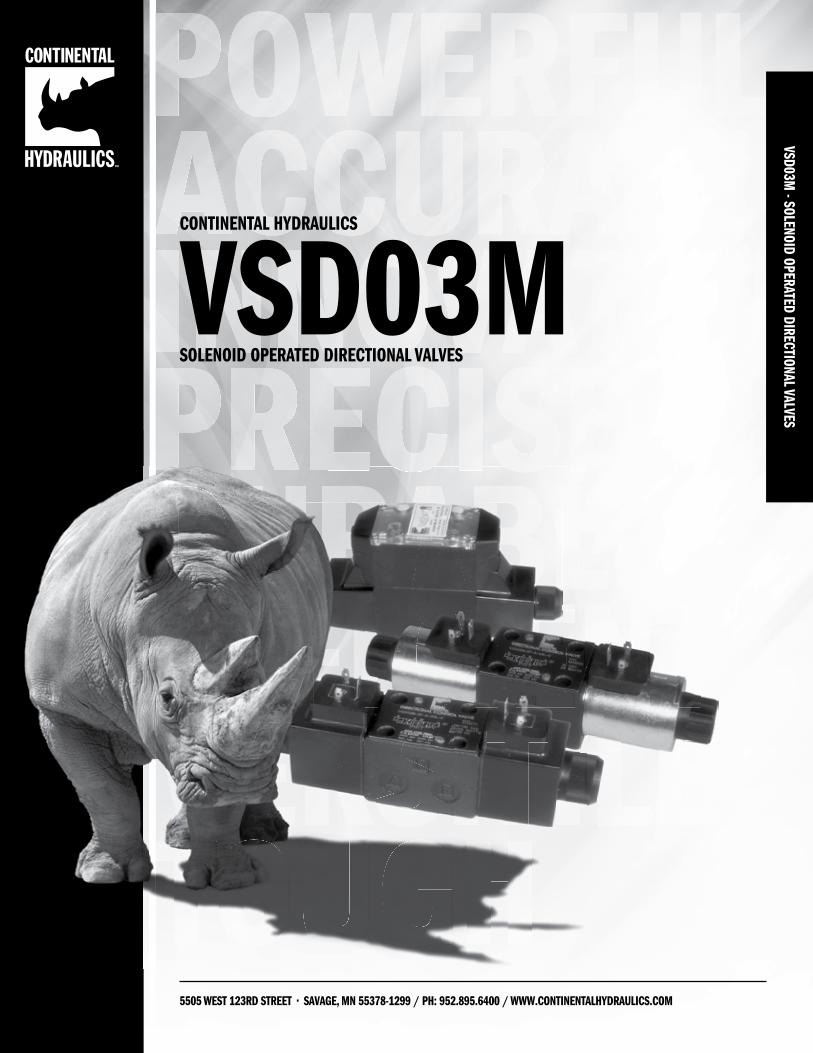
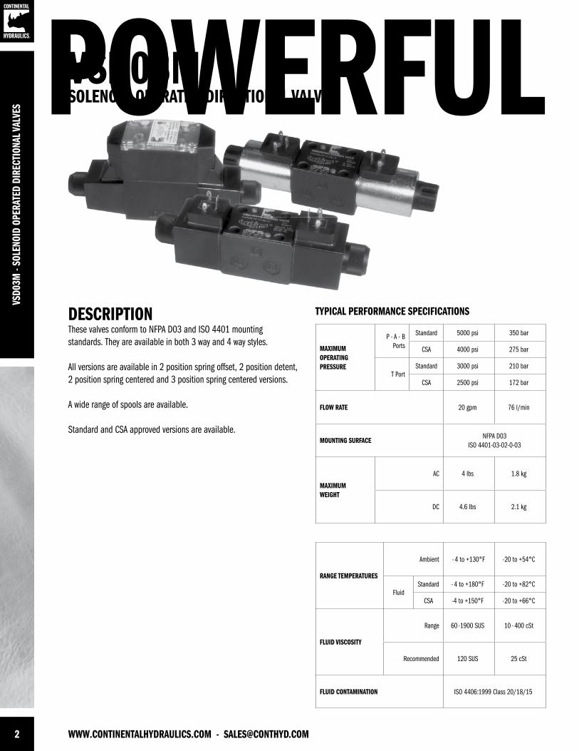
DESCRIPTIONThese valves conform to NFPA D03 and ISO 4401 mounting standards. They are available in both 3 way and 4 way styles.
All versions are available in 2 position spring offset, 2 position detent, 2 position spring centered and 3 position spring centered versions.
A wide range of spools are available.
Standard and CSA approved versions are available.
TYPICAL PERFORMANCE SPECIFICATIONS
MAXIMUM OPERATINGPRESSURE
P - A - B Ports
Standard 5000 psi 350 bar
CSA 4000 psi 275 bar
T Port Standard 3000 psi 210 bar
CSA 2500 psi 172 bar
FLOW RATE 20 gpm 76 l/min
MOUNTING SURFACENFPA D03
ISO 4401-03-02-0-03
MAXIMUMWEIGHT
AC 4 lbs 1.8 kg
DC 4.6 lbs 2.1 kg
RANGE TEMPERATURES
Ambient - 4 to +130°F -20 to +54°C
FluidStandard - 4 to +180°F -20 to +82°C
CSA -4 to +150°F -20 to +66°C
FLUID VISCOSITY
Range 60 -1900 SUS 10 - 400 cSt
Recommended 120 SUS 25 cSt
FLUID CONTAMINATION ISO 4406:1999 Class 20/18/15
[email protected] - WWW.CONTINENTALHYDRAULICS.COM 3
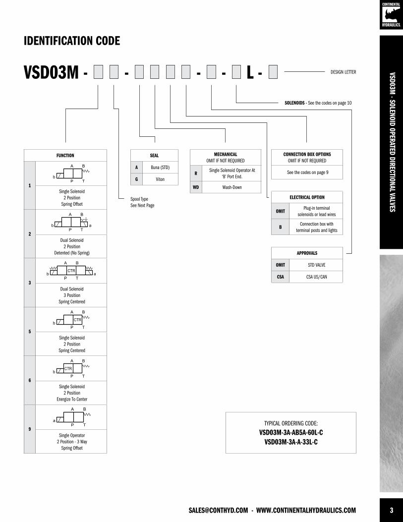
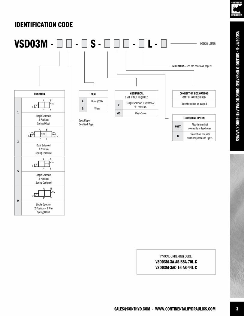
SEAL
A Buna (STD)
G Viton
MECHANICALOMIT IF NOT REQUIRED
RSingle Solenoid Operator At
‘B’ Port End.
WD Wash-Down
CONNECTION BOX OPTIONSOMIT IF NOT REQUIRED
See the codes on page 9
ELECTRICAL OPTION
OMITPlug-in terminal
solenoids or lead wires
BConnection box with
terminal posts and lights
VSD03M - L -- - -
TYPICAL ORDERING CODE:
VSD03M-3A-AB5A-60L-C VSD03M-3A-A-33L-C
IDENTIFICATION CODE
DESIGN LETTER
Spool TypeSee Next Page
SOLENOIDS - See the codes on page 10
VSD03M - SOLENOID OPERATED DIRECTIONAL VALVES
FUNCTION
1Single Solenoid
2 PositionSpring Offset
2Dual Solenoid
2 PositionDetented (No Spring)
3Dual Solenoid
3 PositionSpring Centered
5Single Solenoid
2 PositionSpring Centered
6Single Solenoid
2 PositionEnergize To Center
9Single Operator
2 Position - 3 WaySpring Offset
APPROVALS
OMIT STD VALVE
CSA CSA US/CAN
4 WWW.CONTINENTALHYDRAULICS.COM - [email protected]
VSD0
3M -
SOLE
NOID
OPE
RATE
D DI
RECT
IONA
L VAL
VES
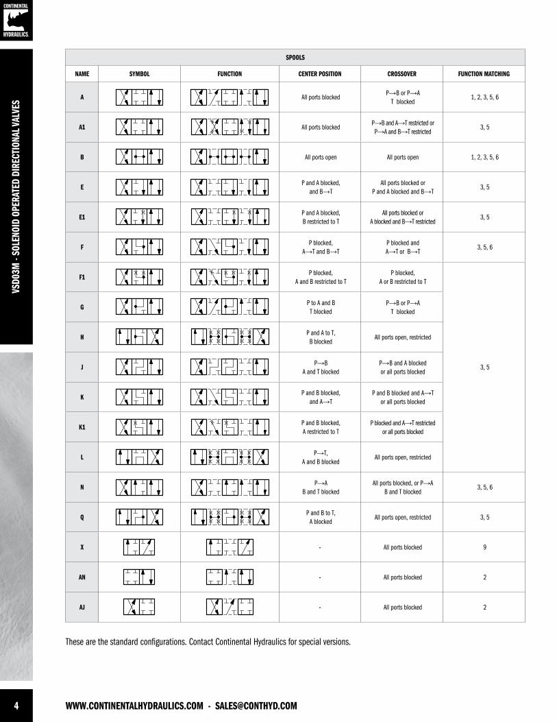
SPOOLS
NAME SYMBOL FUNCTION CENTER POSITION CROSSOVER FUNCTION MATCHING
A All ports blockedP→B or P→A
T blocked1, 2, 3, 5, 6
A1 All ports blockedP→B and A→T restricted or P→A and B→T restricted
3, 5
B All ports open All ports open 1, 2, 3, 5, 6
EP and A blocked,
and B→TAll ports blocked or
P and A blocked and B→T3, 5
E1P and A blocked, B restricted to T
All ports blocked or A blocked and B→T restricted
3, 5
FP blocked,
A→T and B→TP blocked and A→T or B→T
3, 5, 6
F1P blocked,
A and B restricted to TP blocked,
A or B restricted to T
3, 5
GP to A and B T blocked
P→B or P→A T blocked
HP and A to T,B blocked
All ports open, restricted
JP→B
A and T blockedP→B and A blocked or all ports blocked
KP and B blocked,
and A→TP and B blocked and A→T
or all ports blocked
K1P and B blocked, A restricted to T
P blocked and A→T restricted or all ports blocked
LP→T,
A and B blockedAll ports open, restricted
NP→A
B and T blockedAll ports blocked, or P→A
B and T blocked3, 5, 6
QP and B to T,
A blockedAll ports open, restricted 3, 5
X - All ports blocked 9
AN - All ports blocked 2
AJ - All ports blocked 2
These are the standard configurations. Contact Continental Hydraulics for special versions.
[email protected] - WWW.CONTINENTALHYDRAULICS.COM 5
VSD03M - SOLENOID OPERATED DIRECTIONAL VALVES
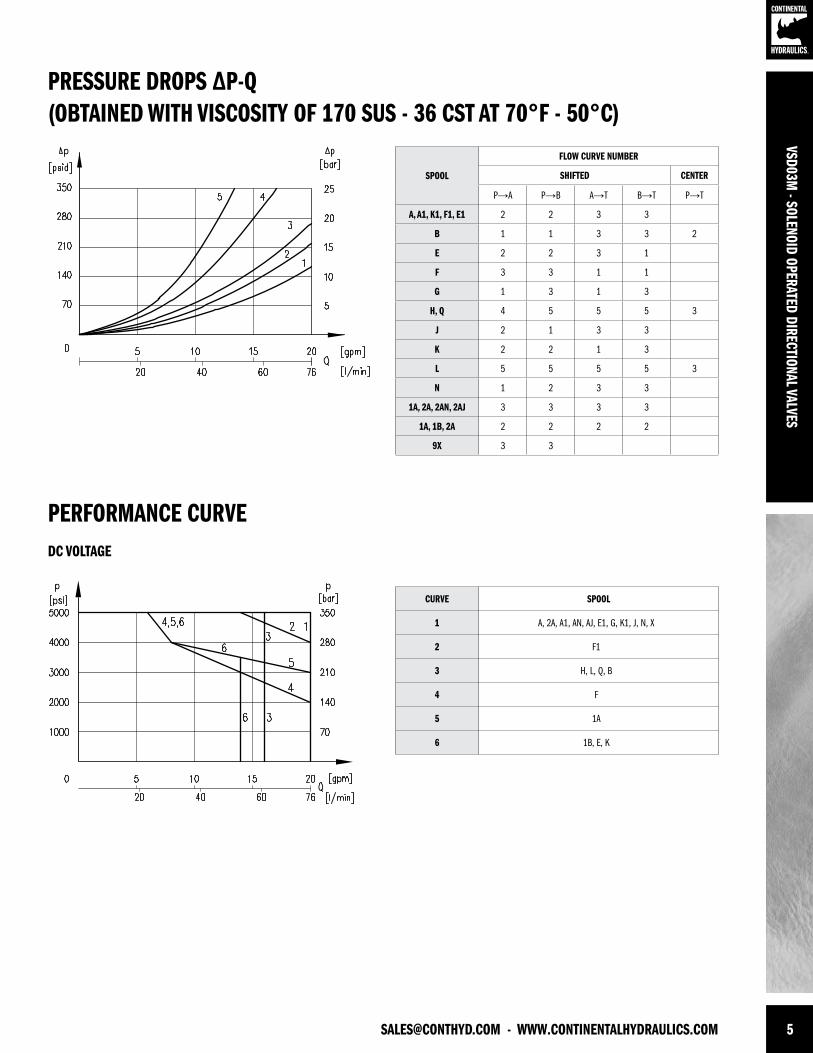
PRESSURE DROPS ∆P-Q(OBTAINED WITH VISCOSITY OF 170 SUS - 36 CST AT 70°F - 50°C)
PERFORMANCE CURVE
SPOOL
FLOW CURVE NUMBER
SHIFTED CENTER
P→A P→B A→T B→T P→T
A, A1, K1, F1, E1 2 2 3 3
B 1 1 3 3 2
E 2 2 3 1
F 3 3 1 1
G 1 3 1 3
H, Q 4 5 5 5 3
J 2 1 3 3
K 2 2 1 3
L 5 5 5 5 3
N 1 2 3 3
1A, 2A, 2AN, 2AJ 3 3 3 3
1A, 1B, 2A 2 2 2 2
9X 3 3
CURVE SPOOL
1 A, 2A, A1, AN, AJ, E1, G, K1, J, N, X
2 F1
3 H, L, Q, B
4 F
5 1A
6 1B, E, K
DC VOLTAGE
6 WWW.CONTINENTALHYDRAULICS.COM - [email protected]
VSD0
3M -
SOLE
NOID
OPE
RATE
D DI
RECT
IONA
L VAL
VES
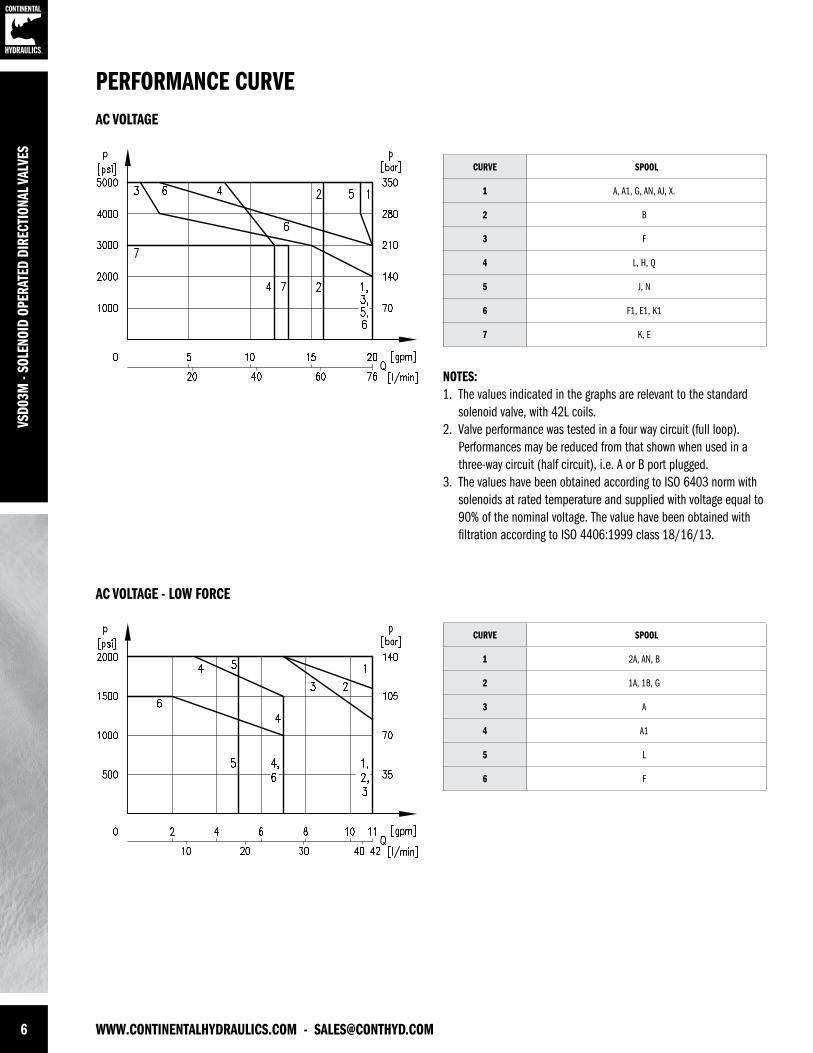
NOTES:1. The values indicated in the graphs are relevant to the standard solenoid valve, with 42L coils. 2. Valve performance was tested in a four way circuit (full loop). Performances may be reduced from that shown when used in a three-way circuit (half circuit), i.e. A or B port plugged.3. The values have been obtained according to ISO 6403 norm with solenoids at rated temperature and supplied with voltage equal to 90% of the nominal voltage. The value have been obtained with filtration according to ISO 4406:1999 class 18/16/13.
PERFORMANCE CURVE
CURVE SPOOL
1 A, A1, G, AN, AJ, X.
2 B
3 F
4 L, H, Q
5 J, N
6 F1, E1, K1
7 K, E
CURVE SPOOL
1 2A, AN, B
2 1A, 1B, G
3 A
4 A1
5 L
6 F
AC VOLTAGE
AC VOLTAGE - LOW FORCE
[email protected] - WWW.CONTINENTALHYDRAULICS.COM 7
VSD03M - SOLENOID OPERATED DIRECTIONAL VALVES
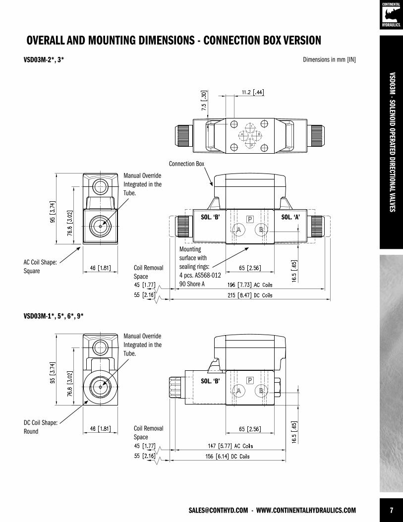
OVERALL AND MOUNTING DIMENSIONS - CONNECTION BOX VERSIONDimensions in mm [IN]VSD03M-2*, 3*
Mounting surface with sealing rings:4 pcs. AS568-012 90 Shore A
AC Coil Shape: Square
Connection Box
Manual OverrideIntegrated in the Tube.
Manual OverrideIntegrated in the Tube.
Coil Removal Space
Coil Removal Space
DC Coil Shape: Round
SOL. ‘A’SOL. ‘B’
SOL. ‘B’
VSD03M-1*, 5*, 6*, 9*
8 WWW.CONTINENTALHYDRAULICS.COM - [email protected]
VSD0
3M -
SOLE
NOID
OPE
RATE
D DI
RECT
IONA
L VAL
VES
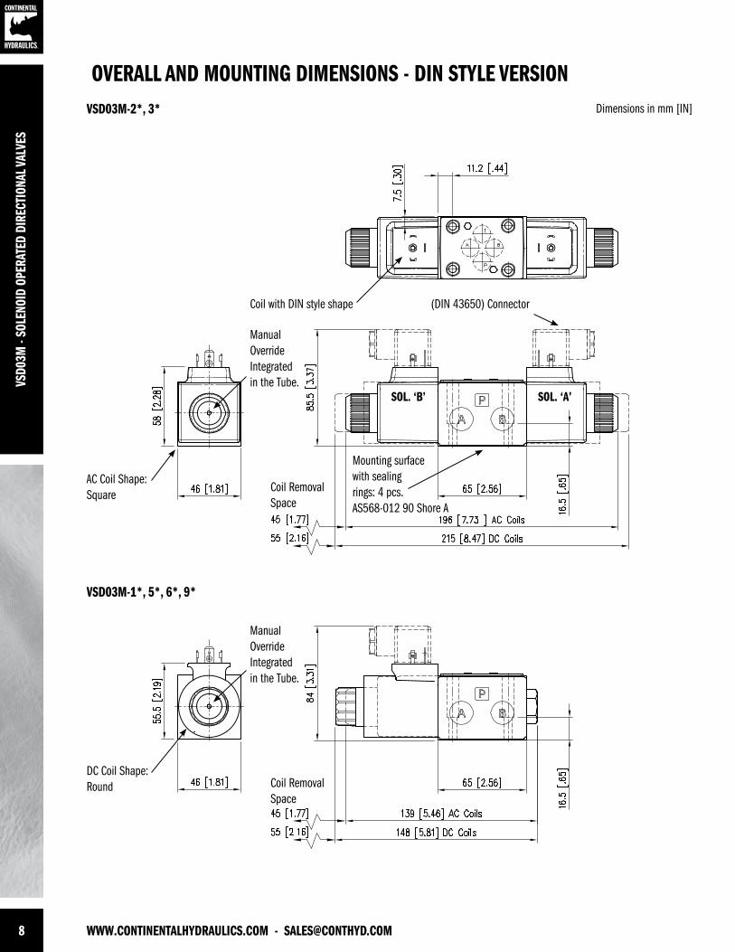
OVERALL AND MOUNTING DIMENSIONS - DIN STYLE VERSIONDimensions in mm [IN]VSD03M-2*, 3*
VSD03M-1*, 5*, 6*, 9*
Mounting surfacewith sealingrings: 4 pcs.AS568-012 90 Shore A
Coil with DIN style shape (DIN 43650) Connector
DC Coil Shape: Round
AC Coil Shape: Square
Coil Removal Space
Coil Removal Space
SOL. ‘A’SOL. ‘B’
Manual OverrideIntegrated in the Tube.
Manual OverrideIntegrated in the Tube.

[email protected] - WWW.CONTINENTALHYDRAULICS.COM 9
VSD03M - SOLENOID OPERATED DIRECTIONAL VALVES
ELECTRICAL CHARACTERISTICSValves are available with an electrical connection box or with DIN 43650 solenoids in both AC andDC voltages. Deutsch DT04 or lead wires are also available in DC voltages only.
CONNECTION BOX OPTIONSTo simplify the connections and prevent wiring mistakes, we offer the option with connection boxes with quick connect pin receptacles, already wired.
Valves are available with receptacles on solenoid side ‘A’ or ‘B’ and several connector styles.
Below are the codes to be included in the box ‘option’ of the ordering code, depending on theversion you choose.
Wiring diagrams at right show the standard connections for 3-pin, 4-pin and 5-pin connectors. Thecommercially available mating “female” connector are not included.
CODE PIN SHAPE PORT END NOTES
5A 5Male Mini
A Single and DualSolenoid5H 5 B
3A 3Male Mini
ASingle Solenoid Only
3H 3 B
4A 4
Male Micro
A
For DC Current Only. Different Wiring.See Schematics.
D4A 4 A
4 4 B
D4 4 B
5 PIN RECEPTACLEMale mini receptacles conform to NFPA/T3.5.29 R1 - 2007 used with single or double solenoid valve.
26 mm [1” ] Wrench
3 PIN RECEPTACLEMale mini receptacles conform to NFPA/T3.5.29 R1 - 2007 used with single solenoid valve.
26 mm [1” ] Wrench
4 PIN RECEPTACLEMale micro receptacles (M12x1 thread) used with DC valve only.
23 mm [7/8] Wrench
1 Lead to Solenoid B2 Lead to Solenoid A3 Ground Lead (Green)4 Lead to Solenoid A5 Lead to Solenoid B
1 Ground Lead (Green)2 Lead to Solenoid3 Lead to Solenoid
4A & 41 Brown Lead to Solenoid A2 White No Connection3 Blue Common Lead to Sol. A & B4 Black Lead to Solendoid B
D4A & D41 Brown No Connection2 White Lead to Solenoid A3 Blue Common Lead to Sol. A & B4 Black Lead to Solendoid B
10 WWW.CONTINENTALHYDRAULICS.COM - [email protected]
VSD0
3M -
SOLE
NOID
OPE
RATE
D DI
RECT
IONA
L VAL
VES
DEUTSCH DT04 MALE
LEAD WIRES
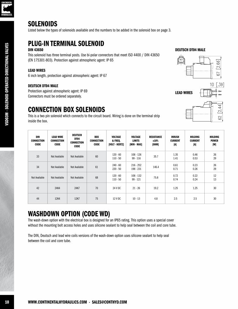
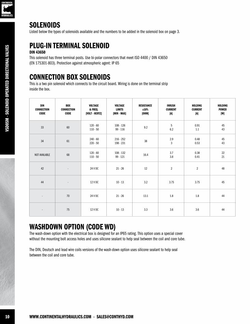
SOLENOIDSListed below the types of solenoids available and the numbers to be added in the solenoid box on page 3.
PLUG-IN TERMINAL SOLENOID DIN 43650 This solenoid has three terminal posts. Use bi-polar connectors that meet ISO 4400 / DIN 43650(EN 175301-803). Protection against atmospheric agent: IP 65
LEAD WIRES6 inch length, protection against atmospheric agent: IP 67
DEUTSCH DT04 MALEProtection against atmospheric agent: IP 69Connectors must be ordered separately.
CONNECTION BOX SOLENOIDS This is a two pin solenoid which connects to the circuit board. Wiring is done on the terminal stripinside the box.
WASHDOWN OPTION (CODE WD)The wash-down option with the electrical box is designed for an IP65 rating. This option uses a special cover without the mounting bolt access holes and uses silicone sealant to help seal between the coil and core tube.
The DIN, Deutsch and lead wire coils versions of the wash-down option uses silicone sealant to help seal between the coil and core tube.
DIN CONNECTION
CODE
LEAD WIRE CONNECTION
CODE
DEUTSCH DT04
CONNECTION CODE
BOX CONNECTION
CODE
VOLTAGE & FREQ.
[VOLT - HERTZ]
VOLTAGE LIMITS
[MIN - MAX]
RESISTANCE±10%[OHM]
INRUSH CURRENT
[A]
HOLDING CURRENT
[A]
HOLDING POWER
[W]
33 Not Available Not Available 60120 - 60110 - 50
108 - 12699 - 116
35.71.351.41
0.460.53
2629
34 Not Available Not Available 61240 - 60 220 - 50
216 - 252198 - 231
146.40.610.71
0.230.26
2629
Not Available Not Available Not Available 68120 - 60110 - 50
108 - 13299 - 121
75.80.720.74
0.220.24
1213
42 24K4 24K7 70 24 V DC 21 - 26 19.2 1.25 1.25 30
44 12K4 12K7 75 12 V DC 10 - 13 4.8 2.5 2.5 30

[email protected] - WWW.CONTINENTALHYDRAULICS.COM 11
VSD03M - SOLENOID OPERATED DIRECTIONAL VALVES
APPLICATION DATAFLUIDS All pressure drops shown on these data pages are based on 170 SUS fluid viscosity and 0.87 specific gravity. For any other specific gravity (G1) the pressure drop (∆P) will be approx. ∆P1 = ∆P (G1/G). See the chart for other viscosities.
Use mineral oil-based hydraulic fluids HL or HM type, according to ISO 6743-4. For these fluids, use NBR seals. For fluids HFDR type (phosphate esters) use FPM seals (code G). For the use of other kinds of fluid such as HFA, HFB, HFC, please consult our technical department.
Using fluids at temperatures higher than 180 degrees F causes the accelerated degradation of seals as well as degradation of the fluids physical and chemical properties.
From a safety standpoint, temperatures above 130 degrees F are not recommended.
FLUIDVISCOSITIES
Cst 10 14.5 32 36 43 54 65 76 86 108 216 324 400
SUS 60 75 150 170 200 250 300 350 400 500 1000 1500 1900
MULTIPIER 0.77 0.81 0.97 1.00 1.04 1.10 1.15 1.20 1.24 1.31 1.56 1.72 1.83
INSTALLATIONValves with centering and return springs can be mounted in any position without impairing correct operation. Valves with mechanical detent should have horizontal mounting.
Valves are fixed by means of screws or tie rods on a flat surface with planarity and roughness equal to or better than those indicated in the relative symbols. If minimum values are not observed, fluid can easily leak between the valve and support surface.
RANGE TEMPERATURES:
Ambient - 4 to +130 °F -20 to +54 °C
FluidSTD - 4 to +180 °F -20 to +82 °C
CSA - 4 to +150 °F -20 to +66 °C
FLUID VISCOSITYRange 60 -1900 SUS 10 - 400 cSt
Recommended 120 SUS 25 cSt
FLUID CONTAMINATION ISO 4406:1999 Class 20/18/15
SEAL KIT
BOLT KIT
Buna Seal Kit 1013326
Viton Seal Sit 1013327
VSD03M 121472

VSD0
3M -
SOLE
NOID
OPE
RATE
D DI
RECT
IONA
L VAL
VES
FORM NO. 1013887. REV. 09/2013. © 2011 CONTINENTAL HYDRAULICS. ALL RIGHTS RESERVED. PRODUCT SPECIFICATIONS AND APPEARANCE ARE SUBJECT TO CHANGE WITHOUT NOTICE.
ABOUT CONTINENTAL HYDRAULICSRugged, durable, high-performance, efcient—the reason Continental Hydraulics’ products are used in some of the most challenging applications across the globe. With a commitment to quality customer
support and innovative engineering, Continental’s pumps, valves, power units, mobile and custom products deliver what the markets demand. Continental has been serving the food production, brick
and block, wood products, automotive and machine tool industries since 1962. Learn how our products survive some of the most harsh environments.
[email protected] WEST 123RD STREET • SAVAGE, MN 55378-1299 / PH: 952.895.6400 / FAX: 952.895.6444 / WWW.CONTINENTALHYDRAULICS.COM
VSD03M*-S - SOLENOID OPERATED DIRECTIONAL ANTI-SHOCK VALVES
5505 WEST 123RD STREET • SAVAGE, MN 55378-1299 / PH: 952.895.6400 / WWW.CONTINENTALHYDRAULICS.COM
CONTINENTAL HYDRAULICS
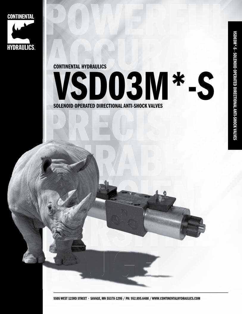
VSD03M*-SSOLENOID OPERATED DIRECTIONAL ANTI-SHOCK VALVES
2 WWW.CONTINENTALHYDRAULICS.COM - [email protected]
DURABLEVS
D03M
*-S
- SOL
ENOI
D OP
ERAT
ED D
IREC
TION
AL A
NTI-S
HOCK
VAL
VES VSD03M*-S
SOLENOID OPERATED DIRECTIONAL ANTI-SHOCK VALVES
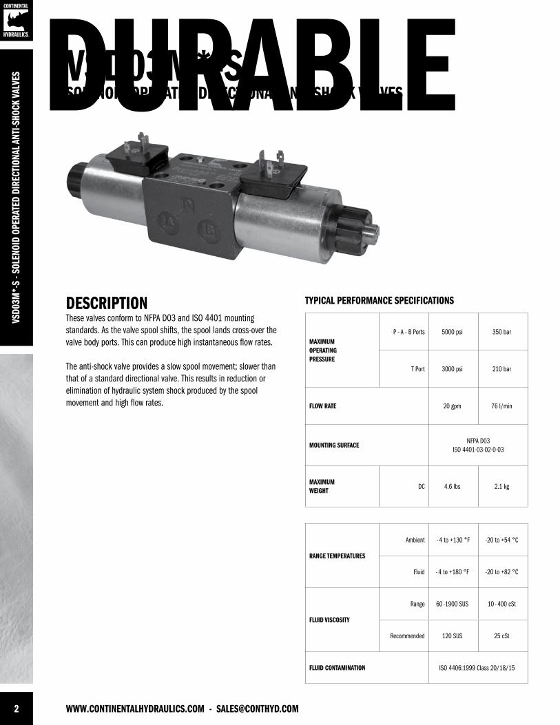
DESCRIPTIONThese valves conform to NFPA D03 and ISO 4401 mounting standards. As the valve spool shifts, the spool lands cross-over the valve body ports. This can produce high instantaneous flow rates.
The anti-shock valve provides a slow spool movement; slower than that of a standard directional valve. This results in reduction orelimination of hydraulic system shock produced by the spool movement and high flow rates.
TYPICAL PERFORMANCE SPECIFICATIONS
MAXIMUM OPERATINGPRESSURE
P - A - B Ports 5000 psi 350 bar
T Port 3000 psi 210 bar
FLOW RATE 20 gpm 76 l/min
MOUNTING SURFACENFPA D03
ISO 4401-03-02-0-03
MAXIMUMWEIGHT
DC 4.6 lbs 2.1 kg
RANGE TEMPERATURES
Ambient - 4 to +130 °F -20 to +54 °C
Fluid - 4 to +180 °F -20 to +82 °C
FLUID VISCOSITY
Range 60 -1900 SUS 10 - 400 cSt
Recommended 120 SUS 25 cSt
FLUID CONTAMINATION ISO 4406:1999 Class 20/18/15
[email protected] - WWW.CONTINENTALHYDRAULICS.COM 3
SEAL
A Buna (STD)
G Viton
MECHANICALOMIT IF NOT REQUIRED
RSingle Solenoid Operator At
‘B’ Port End.
WD Wash-Down
CONNECTION BOX OPTIONSOMIT IF NOT REQUIRED
See the codes on page 8
ELECTRICAL OPTION
OMITPlug-in terminal
solenoids or lead wires
BConnection box with
terminal posts and lights
VSD03M - L -- -
TYPICAL ORDERING CODE:
VSD03M-3A-AS-B5A-70L-CVSD03M-3AC-16-AS-44L-C
IDENTIFICATION CODE
DESIGN LETTER
Spool TypeSee Next Page
SOLENOIDS - See the codes on page 9
VSD03M*-S - SOLENOID OPERATED DIRECTIONAL ANTI-SHOCK VALVES
FUNCTION
1Single Solenoid
2 PositionSpring Offset
3Dual Solenoid
3 PositionSpring Centered
5Single Solenoid
2 PositionSpring Centered
9Single Operator
2 Position - 3 WaySpring Offset
S -
4 WWW.CONTINENTALHYDRAULICS.COM - [email protected]
VSD0
3M*-
S - S
OLEN
OID
OPER
ATED
DIR
ECTI
ONAL
ANT
I-SHO
CK V
ALVE
S
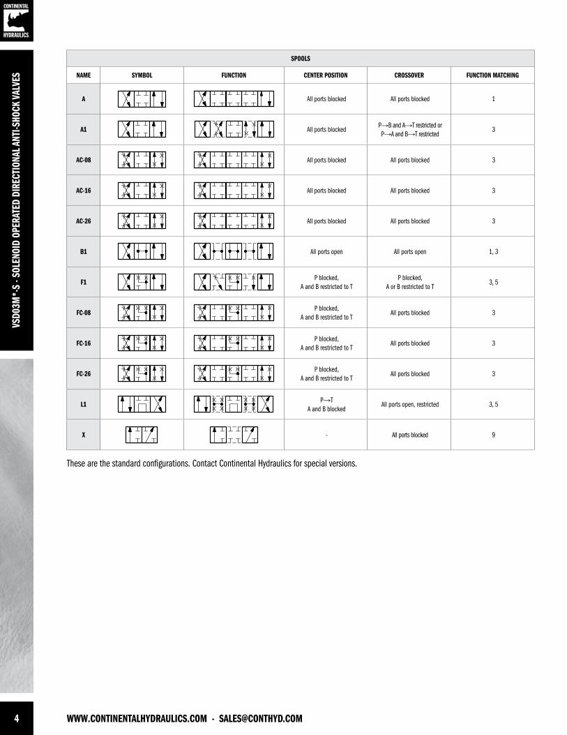
SPOOLS
NAME SYMBOL FUNCTION CENTER POSITION CROSSOVER FUNCTION MATCHING
A All ports blocked All ports blocked 1
A1 All ports blockedP→B and A→T restricted or P→A and B→T restricted
3
AC-08 All ports blocked All ports blocked 3
AC-16 All ports blocked All ports blocked 3
AC-26 All ports blocked All ports blocked 3
B1 All ports open All ports open 1, 3
F1P blocked,
A and B restricted to TP blocked,
A or B restricted to T3, 5
FC-08P blocked,
A and B restricted to TAll ports blocked 3
FC-16P blocked,
A and B restricted to TAll ports blocked 3
FC-26P blocked,
A and B restricted to TAll ports blocked 3
L1P→T
A and B blockedAll ports open, restricted 3, 5
X - All ports blocked 9
These are the standard configurations. Contact Continental Hydraulics for special versions.
[email protected] - WWW.CONTINENTALHYDRAULICS.COM 5
VSD03M*-S - SOLENOID OPERATED DIRECTIONAL ANTI-SHOCK VALVES
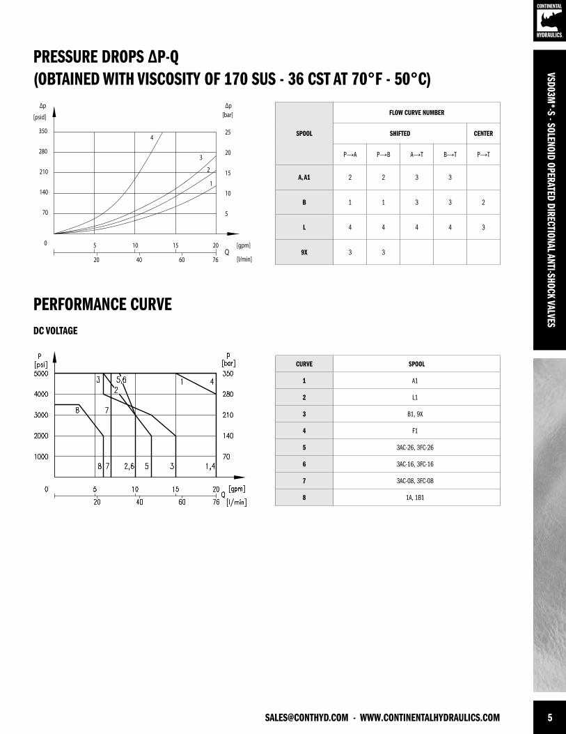
PRESSURE DROPS ∆P-Q(OBTAINED WITH VISCOSITY OF 170 SUS - 36 CST AT 70°F - 50°C)
PERFORMANCE CURVE
SPOOL
FLOW CURVE NUMBER
SHIFTED CENTER
P→A P→B A→T B→T P→T
A, A1 2 2 3 3
B 1 1 3 3 2
L 4 4 4 4 3
9X 3 3
CURVE SPOOL
1 A1
2 L1
3 B1, 9X
4 F1
5 3AC-26, 3FC-26
6 3AC-16, 3FC-16
7 3AC-08, 3FC-08
8 1A, 1B1
70
140
210
280
350
0
[psid]
15
10
25
Δp[bar]
5
20
Q[gpm]
[l/min]
Δp
20
5 10 15 20
40 60 76
1
2
3
4
DC VOLTAGE
6 WWW.CONTINENTALHYDRAULICS.COM - [email protected]
VSD0
3M*-
S - S
OLEN
OID
OPER
ATED
DIR
ECTI
ONAL
ANT
I-SHO
CK V
ALVE
S
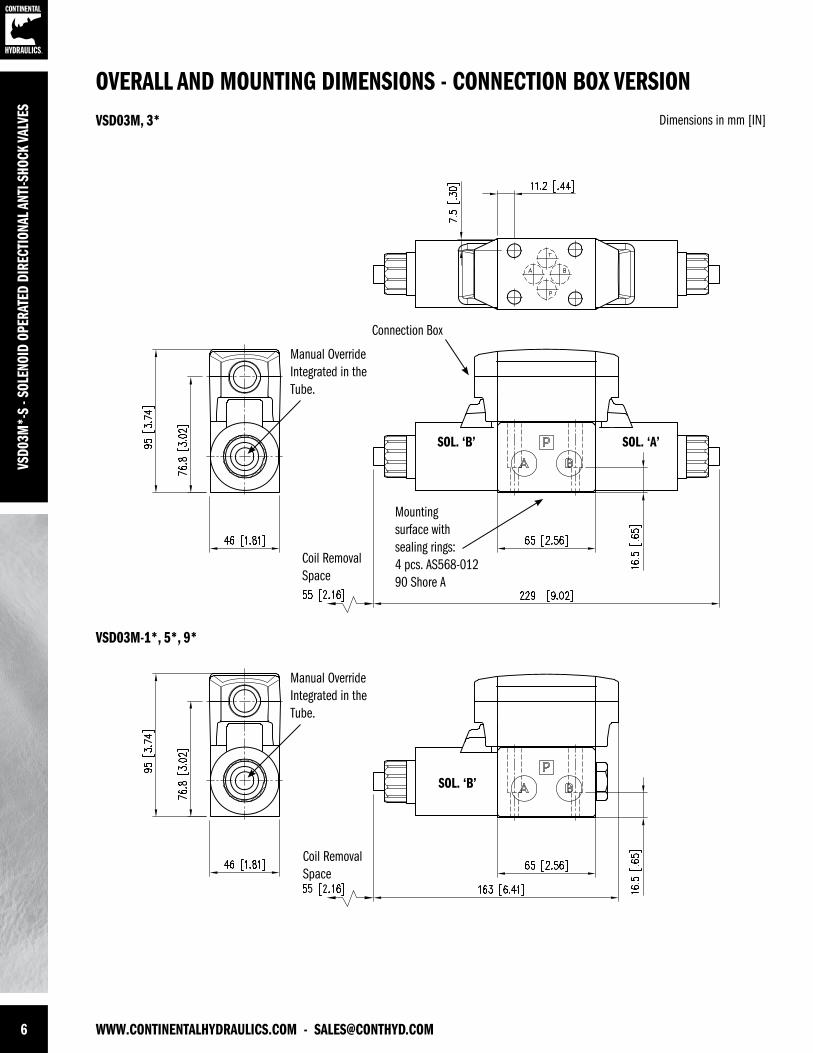
OVERALL AND MOUNTING DIMENSIONS - CONNECTION BOX VERSIONDimensions in mm [IN]VSD03M, 3*
Mounting surface with sealing rings:4 pcs. AS568-012 90 Shore A
Connection Box
Manual OverrideIntegrated in the Tube.
Manual OverrideIntegrated in the Tube.
Coil Removal Space
Coil Removal Space
SOL. ‘A’SOL. ‘B’
SOL. ‘B’
VSD03M-1*, 5*, 9*
[email protected] - WWW.CONTINENTALHYDRAULICS.COM 7
VSD03M*-S - SOLENOID OPERATED DIRECTIONAL ANTI-SHOCK VALVES
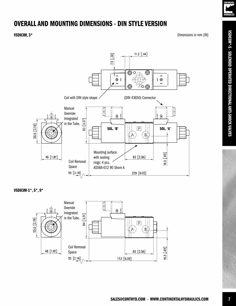
OVERALL AND MOUNTING DIMENSIONS - DIN STYLE VERSIONDimensions in mm [IN]VSD03M, 3*
VSD03M-1*, 5*, 9*
Mounting surfacewith sealingrings: 4 pcs.AS568-012 90 Shore A
Coil with DIN style shape (DIN 43650) Connector
Coil Removal Space
Coil Removal Space
SOL. ‘A’SOL. ‘B’
Manual OverrideIntegrated in the Tube.
Manual OverrideIntegrated in the Tube.
8 WWW.CONTINENTALHYDRAULICS.COM - [email protected]
VSD0
3M*-
S - S
OLEN
OID
OPER
ATED
DIR
ECTI
ONAL
ANT
I-SHO
CK V
ALVE
S
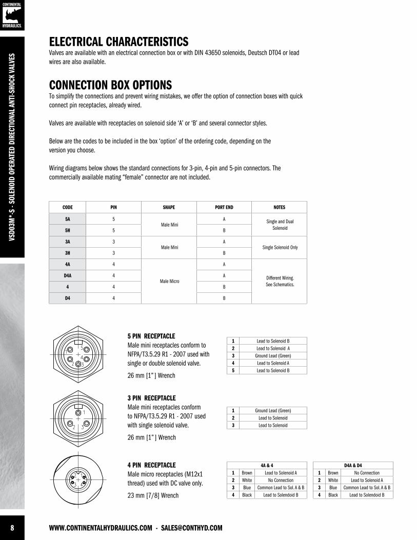
ELECTRICAL CHARACTERISTICSValves are available with an electrical connection box or with DIN 43650 solenoids, Deutsch DT04 or lead wires are also available.
CONNECTION BOX OPTIONSTo simplify the connections and prevent wiring mistakes, we offer the option of connection boxes with quick connect pin receptacles, already wired.
Valves are available with receptacles on solenoid side ‘A’ or ‘B’ and several connector styles.
Below are the codes to be included in the box ‘option’ of the ordering code, depending on theversion you choose.
Wiring diagrams below shows the standard connections for 3-pin, 4-pin and 5-pin connectors. Thecommercially available mating “female” connector are not included.
CODE PIN SHAPE PORT END NOTES
5A 5Male Mini
A Single and DualSolenoid5H 5 B
3A 3Male Mini
ASingle Solenoid Only
3H 3 B
4A 4
Male Micro
A
Different Wiring.See Schematics.
D4A 4 A
4 4 B
D4 4 B
5 PIN RECEPTACLEMale mini receptacles conform to NFPA/T3.5.29 R1 - 2007 used with single or double solenoid valve.
26 mm [1” ] Wrench
3 PIN RECEPTACLEMale mini receptacles conform to NFPA/T3.5.29 R1 - 2007 used with single solenoid valve.
26 mm [1” ] Wrench
4 PIN RECEPTACLEMale micro receptacles (M12x1 thread) used with DC valve only.
23 mm [7/8] Wrench
1 Lead to Solenoid B2 Lead to Solenoid A3 Ground Lead (Green)4 Lead to Solenoid A5 Lead to Solenoid B
1 Ground Lead (Green)2 Lead to Solenoid3 Lead to Solenoid
4A & 41 Brown Lead to Solenoid A2 White No Connection3 Blue Common Lead to Sol. A & B4 Black Lead to Solendoid B
D4A & D41 Brown No Connection2 White Lead to Solenoid A3 Blue Common Lead to Sol. A & B4 Black Lead to Solendoid B
[email protected] - WWW.CONTINENTALHYDRAULICS.COM 9
VSD03M*-S - SOLENOID OPERATED DIRECTIONAL ANTI-SHOCK VALVES
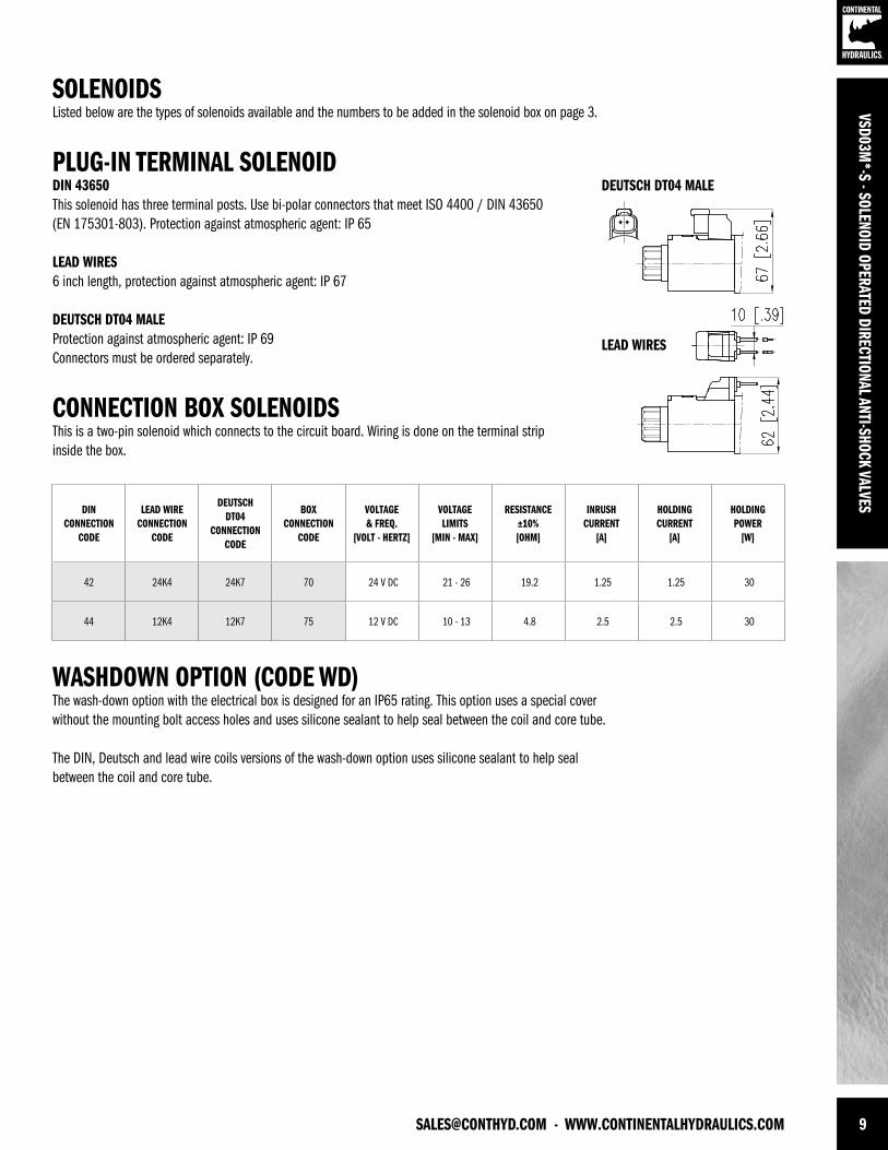
DEUTSCH DT04 MALE
LEAD WIRES
SOLENOIDSListed below are the types of solenoids available and the numbers to be added in the solenoid box on page 3.
PLUG-IN TERMINAL SOLENOID DIN 43650 This solenoid has three terminal posts. Use bi-polar connectors that meet ISO 4400 / DIN 43650(EN 175301-803). Protection against atmospheric agent: IP 65
LEAD WIRES6 inch length, protection against atmospheric agent: IP 67
DEUTSCH DT04 MALEProtection against atmospheric agent: IP 69Connectors must be ordered separately.
CONNECTION BOX SOLENOIDS This is a two-pin solenoid which connects to the circuit board. Wiring is done on the terminal stripinside the box.
WASHDOWN OPTION (CODE WD)The wash-down option with the electrical box is designed for an IP65 rating. This option uses a special cover without the mounting bolt access holes and uses silicone sealant to help seal between the coil and core tube.
The DIN, Deutsch and lead wire coils versions of the wash-down option uses silicone sealant to help seal between the coil and core tube.
DIN CONNECTION
CODE
LEAD WIRE CONNECTION
CODE
DEUTSCH DT04
CONNECTION CODE
BOX CONNECTION
CODE
VOLTAGE & FREQ.
[VOLT - HERTZ]
VOLTAGE LIMITS
[MIN - MAX]
RESISTANCE±10%[OHM]
INRUSH CURRENT
[A]
HOLDING CURRENT
[A]
HOLDING POWER
[W]
42 24K4 24K7 70 24 V DC 21 - 26 19.2 1.25 1.25 30
44 12K4 12K7 75 12 V DC 10 - 13 4.8 2.5 2.5 30
10 WWW.CONTINENTALHYDRAULICS.COM - [email protected]
VSD0
3M*-
S - S
OLEN
OID
OPER
ATED
DIR
ECTI
ONAL
ANT
I-SHO
CK V
ALVE
S
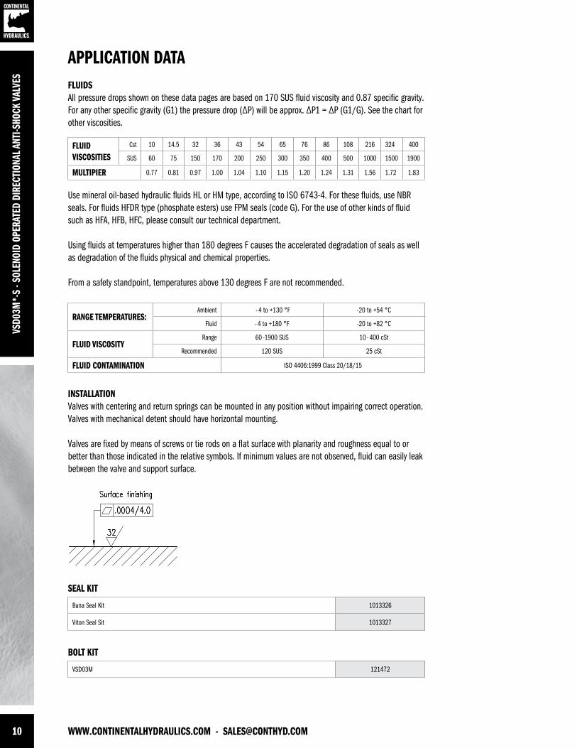
APPLICATION DATAFLUIDS All pressure drops shown on these data pages are based on 170 SUS fluid viscosity and 0.87 specific gravity. For any other specific gravity (G1) the pressure drop (∆P) will be approx. ∆P1 = ∆P (G1/G). See the chart for other viscosities.
Use mineral oil-based hydraulic fluids HL or HM type, according to ISO 6743-4. For these fluids, use NBR seals. For fluids HFDR type (phosphate esters) use FPM seals (code G). For the use of other kinds of fluid such as HFA, HFB, HFC, please consult our technical department.
Using fluids at temperatures higher than 180 degrees F causes the accelerated degradation of seals as well as degradation of the fluids physical and chemical properties.
From a safety standpoint, temperatures above 130 degrees F are not recommended.
FLUIDVISCOSITIES
Cst 10 14.5 32 36 43 54 65 76 86 108 216 324 400
SUS 60 75 150 170 200 250 300 350 400 500 1000 1500 1900
MULTIPIER 0.77 0.81 0.97 1.00 1.04 1.10 1.15 1.20 1.24 1.31 1.56 1.72 1.83
INSTALLATIONValves with centering and return springs can be mounted in any position without impairing correct operation. Valves with mechanical detent should have horizontal mounting.
Valves are fixed by means of screws or tie rods on a flat surface with planarity and roughness equal to or better than those indicated in the relative symbols. If minimum values are not observed, fluid can easily leak between the valve and support surface.
RANGE TEMPERATURES: Ambient - 4 to +130 °F -20 to +54 °C
Fluid - 4 to +180 °F -20 to +82 °C
FLUID VISCOSITYRange 60 -1900 SUS 10 - 400 cSt
Recommended 120 SUS 25 cSt
FLUID CONTAMINATION ISO 4406:1999 Class 20/18/15
SEAL KIT
BOLT KIT
Buna Seal Kit 1013326
Viton Seal Sit 1013327
VSD03M 121472

[email protected] - WWW.CONTINENTALHYDRAULICS.COM 11
VSD03M*-S - SOLENOID OPERATED DIRECTIONAL ANTI-SHOCK VALVES

VSD0
3M*-
S - S
OLEN
OID
OPER
ATED
DIR
ECTI
ONAL
ANT
I-SHO
CK V
ALVE
S
FORM NO. 1015682. REV. 01/2013. © 2012 CONTINENTAL HYDRAULICS. ALL RIGHTS RESERVED. PRODUCT SPECIFICATIONS AND APPEARANCE ARE SUBJECT TO CHANGE WITHOUT NOTICE.
ABOUT CONTINENTAL HYDRAULICSRugged, durable, high-performance, efcient—the reason Continental Hydraulics’ products are used in some of the most challenging applications across the globe. With a commitment to quality customer
support and innovative engineering, Continental’s pumps, valves, power units, mobile and custom products deliver what the markets demand. Continental has been serving the food production, brick
and block, wood products, automotive and machine tool industries since 1962. Learn how our products survive some of the most harsh environments.
[email protected] WEST 123RD STREET • SAVAGE, MN 55378-1299 / PH: 952.895.6400 / FAX: 952.895.6444 / WWW.CONTINENTALHYDRAULICS.COM
VSD05M - SOLENOID OPERATED DIRECTIONAL VALVES
5505 WEST 123RD STREET • SAVAGE, MN 55378-1299 / PH: 952.895.6400 / WWW.CONTINENTALHYDRAULICS.COM
CONTINENTAL HYDRAULICS
SOLENOID OPERATED DIRECTIONAL VALVESVSD05M
2 WWW.CONTINENTALHYDRAULICS.COM - [email protected]
ACCURATEVS
D05M
- SO
LENO
ID O
PERA
TED
DIRE
CTIO
NAL V
ALVE
S
VSD05MSOLENOID OPERATED DIRECTIONAL VALVES
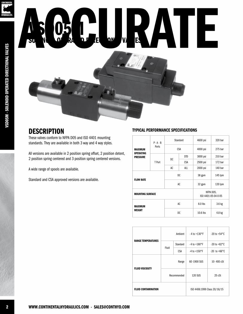
DESCRIPTIONThese valves conform to NFPA D05 and ISO 4401 mounting standards. They are available in both 3 way and 4 way styles.
All versions are available in 2 position spring offset, 2 position detent, 2 position spring centered and 3 position spring centered versions.
A wide range of spools are available.
Standard and CSA approved versions are available.
TYPICAL PERFORMANCE SPECIFICATIONS
MAXIMUM OPERATINGPRESSURE
P - A - B Ports
Standard 4600 psi 320 bar
CSA 4000 psi 275 bar
T Port DC
STD 3000 psi 210 bar
CSA 2500 psi 172 bar
AC ALL 2000 psi 140 bar
FLOW RATEDC 38 gpm 145 lpm
AC 32 gpm 120 lpm
MOUNTING SURFACENFPA D05,
ISO 4401-05-04-0-05
MAXIMUMWEIGHT
AC 8.0 lbs 3.6 kg
DC 10.6 lbs 4.8 kg
RANGE TEMPERATURES
Ambient - 4 to +130°F -20 to +54°C
FluidStandard - 4 to +180°F -20 to +82°C
CSA -4 to +150°F -20 to +66°C
FLUID VISCOSITY
Range 60 -1900 SUS 10 - 400 cSt
Recommended 120 SUS 25 cSt
FLUID CONTAMINATION ISO 4406:1999 Class 20/18/15
[email protected] - WWW.CONTINENTALHYDRAULICS.COM 3
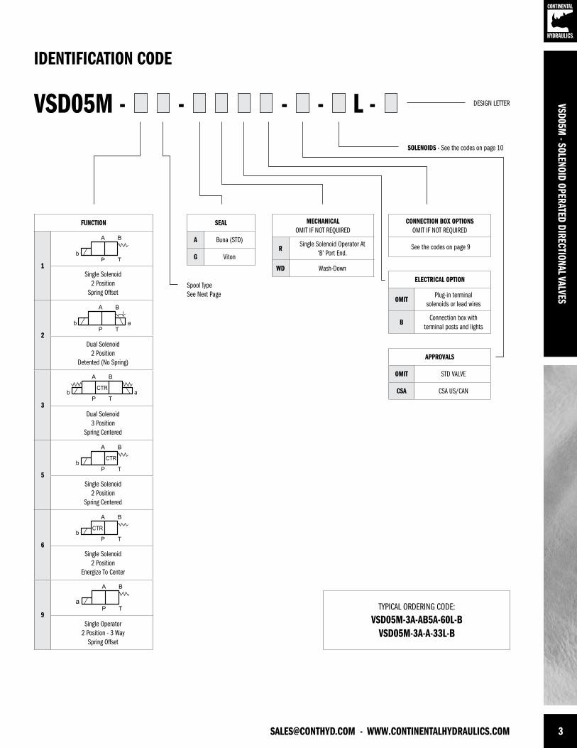
SEAL
A Buna (STD)
G Viton
MECHANICALOMIT IF NOT REQUIRED
RSingle Solenoid Operator At
‘B’ Port End.
WD Wash-Down
ELECTRICAL OPTION
OMITPlug-in terminal
solenoids or lead wires
BConnection box with
terminal posts and lights
VSD05M - L -- - -
TYPICAL ORDERING CODE:
VSD05M-3A-AB5A-60L-B VSD05M-3A-A-33L-B
IDENTIFICATION CODE
DESIGN LETTER
Spool TypeSee Next Page
SOLENOIDS - See the codes on page 10
VSD05M - SOLENOID OPERATED DIRECTIONAL VALVES
FUNCTION
1Single Solenoid
2 PositionSpring Offset
2Dual Solenoid
2 PositionDetented (No Spring)
3Dual Solenoid
3 PositionSpring Centered
5Single Solenoid
2 PositionSpring Centered
6Single Solenoid
2 PositionEnergize To Center
9Single Operator
2 Position - 3 WaySpring Offset
CONNECTION BOX OPTIONSOMIT IF NOT REQUIRED
See the codes on page 9
APPROVALS
OMIT STD VALVE
CSA CSA US/CAN
4 WWW.CONTINENTALHYDRAULICS.COM - [email protected]
VSD0
5M -
SOLE
NOID
OPE
RATE
D DI
RECT
IONA
L VAL
VES
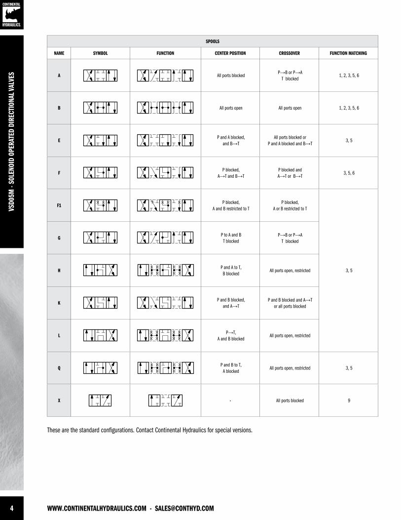
SPOOLS
NAME SYMBOL FUNCTION CENTER POSITION CROSSOVER FUNCTION MATCHING
A All ports blockedP→B or P→A
T blocked1, 2, 3, 5, 6
B All ports open All ports open 1, 2, 3, 5, 6
EP and A blocked,
and B→TAll ports blocked or
P and A blocked and B→T3, 5
FP blocked,
A→T and B→TP blocked and A→T or B→T
3, 5, 6
F1P blocked,
A and B restricted to TP blocked,
A or B restricted to T
3, 5
GP to A and B T blocked
P→B or P→A T blocked
HP and A to T,B blocked
All ports open, restricted
KP and B blocked,
and A→TP and B blocked and A→T
or all ports blocked
LP→T,
A and B blockedAll ports open, restricted
QP and B to T,
A blockedAll ports open, restricted 3, 5
X - All ports blocked 9
These are the standard configurations. Contact Continental Hydraulics for special versions.
[email protected] - WWW.CONTINENTALHYDRAULICS.COM 5
VSD05M - SOLENOID OPERATED DIRECTIONAL VALVES
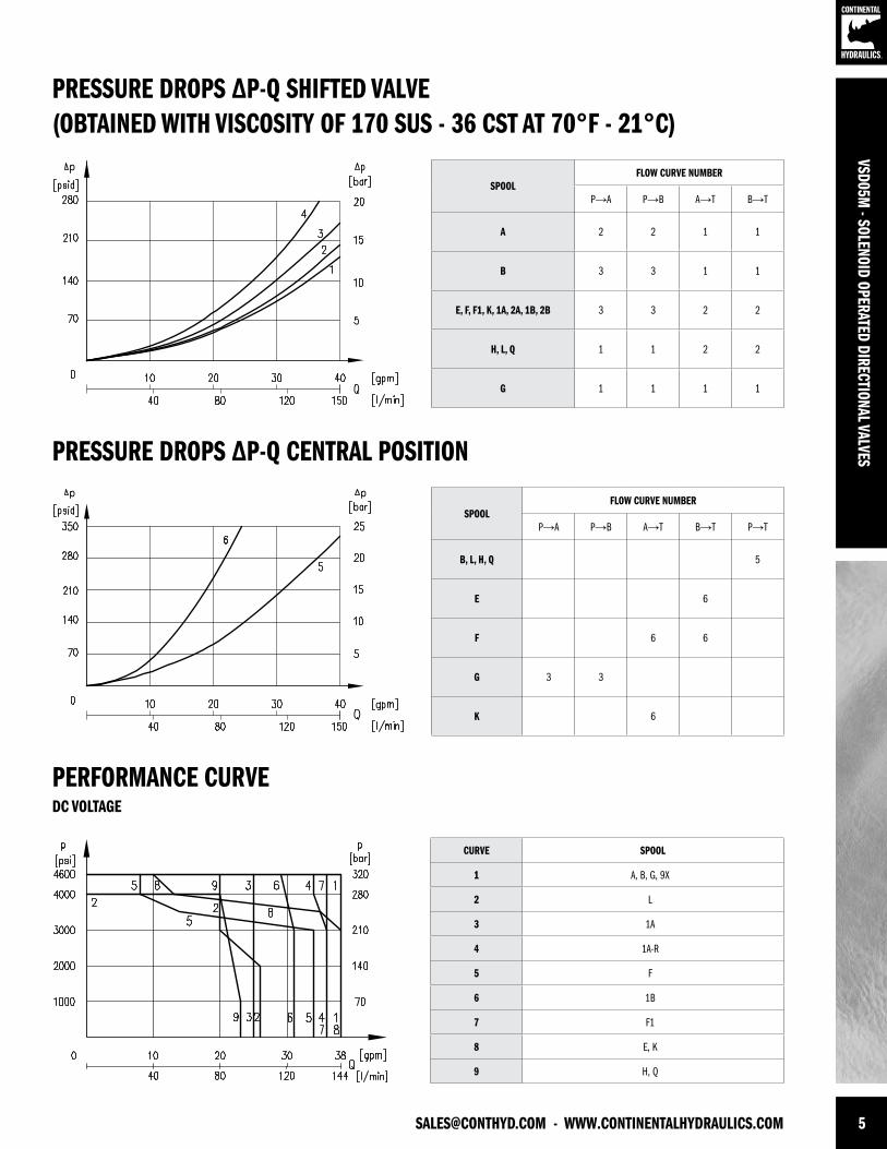
PRESSURE DROPS ∆P-Q SHIFTED VALVE(OBTAINED WITH VISCOSITY OF 170 SUS - 36 CST AT 70°F - 21°C)
PRESSURE DROPS ∆P-Q CENTRAL POSITION
SPOOLFLOW CURVE NUMBER
P→A P→B A→T B→T
A 2 2 1 1
B 3 3 1 1
E, F, F1, K, 1A, 2A, 1B, 2B 3 3 2 2
H, L, Q 1 1 2 2
G 1 1 1 1
SPOOLFLOW CURVE NUMBER
P→A P→B A→T B→T P→T
B, L, H, Q 5
E 6
F 6 6
G 3 3
K 6
PERFORMANCE CURVE
CURVE SPOOL
1 A, B, G, 9X
2 L
3 1A
4 1A-R
5 F
6 1B
7 F1
8 E, K
9 H, Q
DC VOLTAGE
6 WWW.CONTINENTALHYDRAULICS.COM - [email protected]
VSD0
5M -
SOLE
NOID
OPE
RATE
D DI
RECT
IONA
L VAL
VES
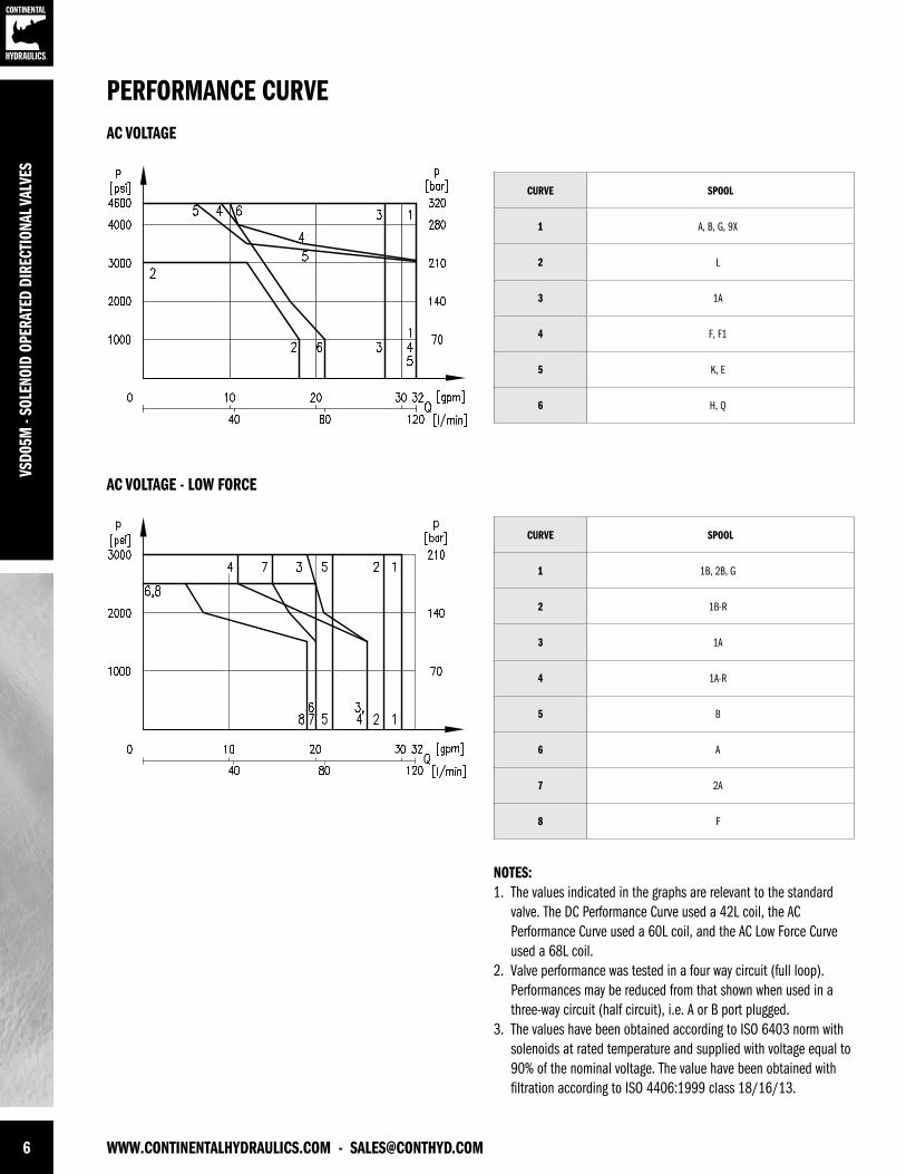
NOTES:1. The values indicated in the graphs are relevant to the standard valve. The DC Performance Curve used a 42L coil, the AC Performance Curve used a 60L coil, and the AC Low Force Curve used a 68L coil. 2. Valve performance was tested in a four way circuit (full loop). Performances may be reduced from that shown when used in a three-way circuit (half circuit), i.e. A or B port plugged.3. The values have been obtained according to ISO 6403 norm with solenoids at rated temperature and supplied with voltage equal to 90% of the nominal voltage. The value have been obtained with filtration according to ISO 4406:1999 class 18/16/13.
PERFORMANCE CURVE
CURVE SPOOL
1 A, B, G, 9X
2 L
3 1A
4 F, F1
5 K, E
6 H, Q
CURVE SPOOL
1 1B, 2B, G
2 1B-R
3 1A
4 1A-R
5 B
6 A
7 2A
8 F
AC VOLTAGE
AC VOLTAGE - LOW FORCE
[email protected] - WWW.CONTINENTALHYDRAULICS.COM 7
VSD05M - SOLENOID OPERATED DIRECTIONAL VALVES
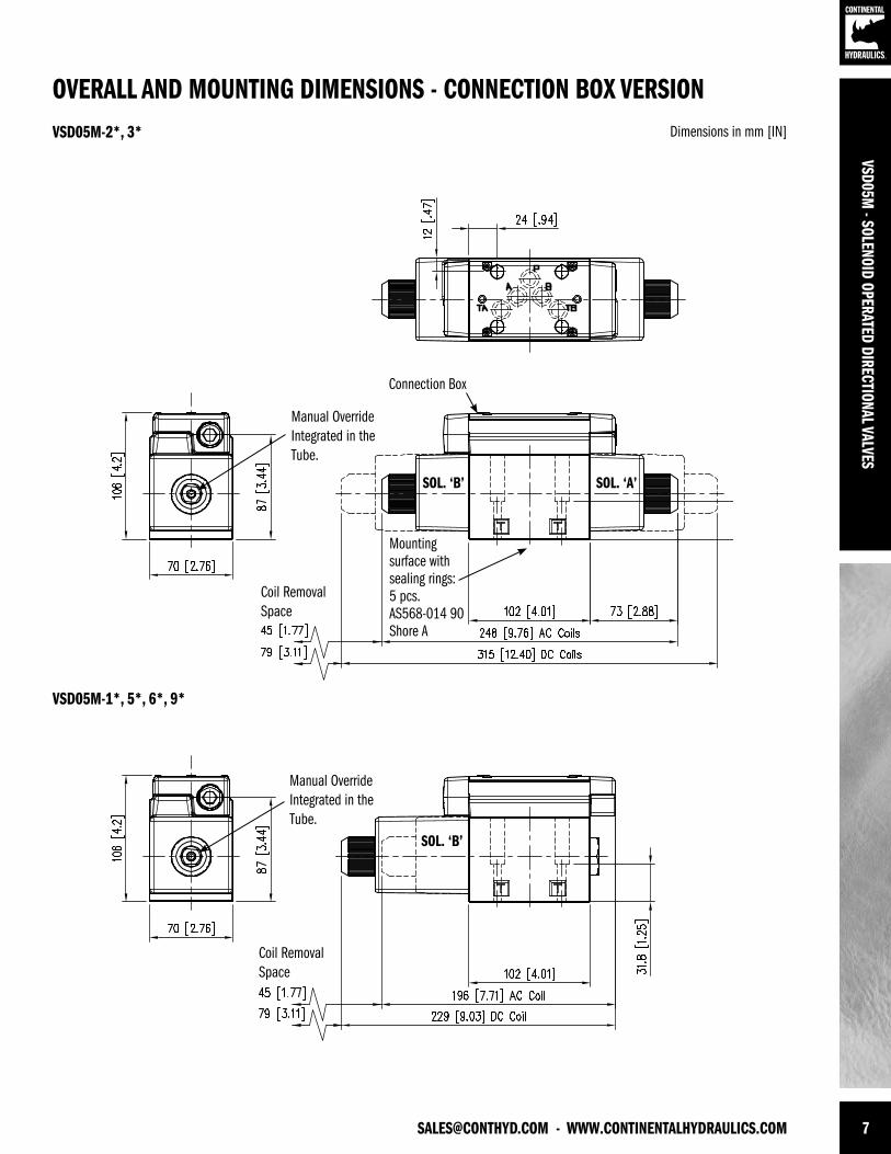
OVERALL AND MOUNTING DIMENSIONS - CONNECTION BOX VERSIONDimensions in mm [IN]VSD05M-2*, 3*
Mounting surface with sealing rings:5 pcs.AS568-014 90 Shore A
Connection Box
Manual OverrideIntegrated in the Tube.
Manual OverrideIntegrated in the Tube.
Coil Removal Space
Coil Removal Space
SOL. ‘A’SOL. ‘B’
SOL. ‘B’
VSD05M-1*, 5*, 6*, 9*
8 WWW.CONTINENTALHYDRAULICS.COM - [email protected]
VSD0
5M -
SOLE
NOID
OPE
RATE
D DI
RECT
IONA
L VAL
VES
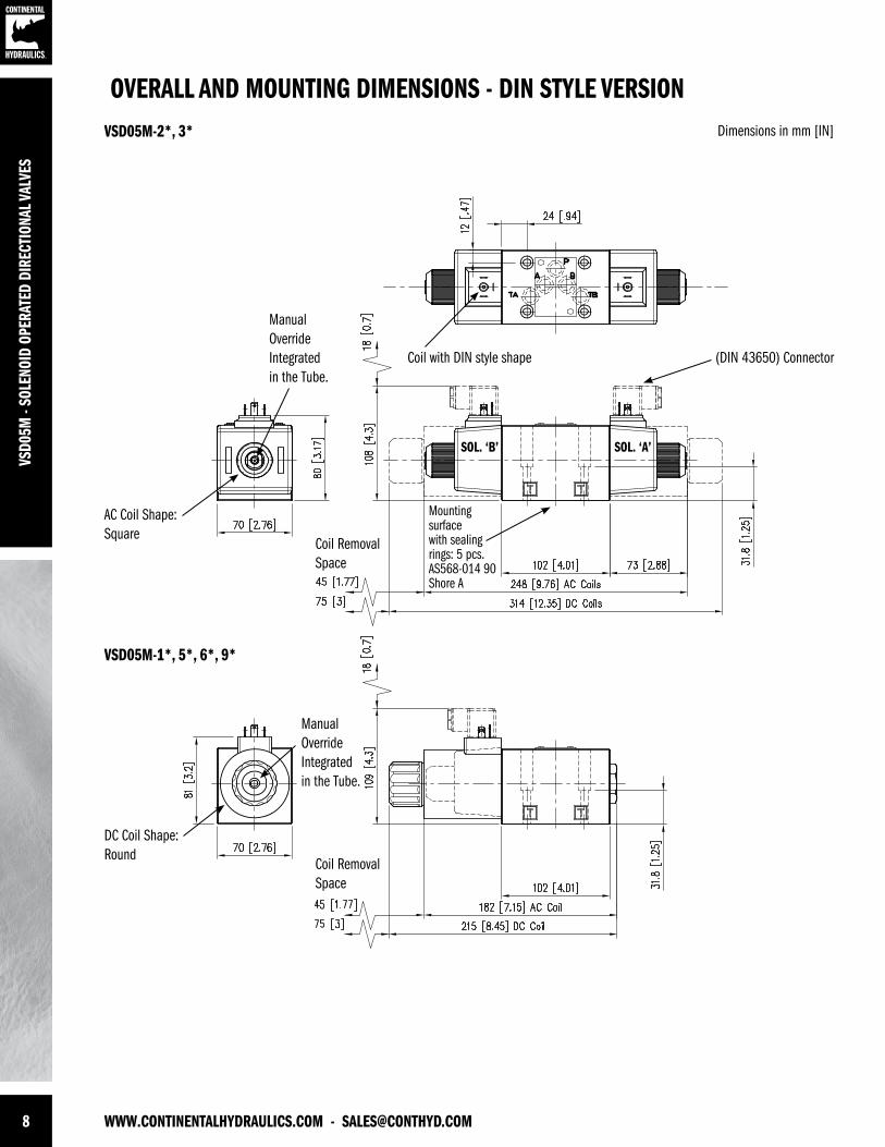
OVERALL AND MOUNTING DIMENSIONS - DIN STYLE VERSIONDimensions in mm [IN]VSD05M-2*, 3*
VSD05M-1*, 5*, 6*, 9*
Mountingsurfacewith sealingrings: 5 pcs.AS568-014 90Shore A
Coil with DIN style shape (DIN 43650) Connector
DC Coil Shape: Round
AC Coil Shape: Square
Coil Removal Space
Coil Removal Space
SOL. ‘A’SOL. ‘B’
Manual OverrideIntegrated in the Tube.
Manual OverrideIntegrated in the Tube.

[email protected] - WWW.CONTINENTALHYDRAULICS.COM 9
VSD05M - SOLENOID OPERATED DIRECTIONAL VALVES
ELECTRICAL CHARACTERISTICSValves are available with an electrical connection box or with DIN 43650 solenoids in both AC andDC voltages. Deutsch DT04 or lead wires are also available in DC voltages only.
CONNECTION BOX OPTIONSTo simplify the connections and prevent wiring mistakes, we offer the option with connection boxes with quick connect pin receptacles, already wired.
Valves are available with receptacles on solenoid side ‘A’ or ‘B’ and several connector styles.
Below are the codes to be included in the box ‘option’ of the ordering code, depending on theversion you choose.
Wiring diagrams below show the standard connections for 3-pin, 4-pin and 5-pin connectors. Thecommercially available mating “female” connector are not included.
CODE PIN SHAPE PORT END NOTES
5A 5Male Mini
A Single and DualSolenoid5H 5 B
3A 3Male Mini
ASingle Solenoid Only
3H 3 B
4A 4
Male Micro
A
For DC Current Only. Different Wiring.See Schematics.
D4A 4 A
4 4 B
D4 4 B
5 PIN RECEPTACLEMale mini receptacles conform to NFPA/T3.5.29 R1 - 2007 used with single or double solenoid valve.
26 mm [1” ] Wrench
3 PIN RECEPTACLEMale mini receptacles conform to NFPA/T3.5.29 R1 - 2007 used with single solenoid valve.
26 mm [1” ] Wrench
4 PIN RECEPTACLEMale micro receptacles (M12x1 thread) used with DC valve only.
23 mm [7/8] Wrench
1 Lead to Solenoid B2 Lead to Solenoid A3 Ground Lead (Green)4 Lead to Solenoid A5 Lead to Solenoid B
1 Ground Lead (Green)2 Lead to Solenoid3 Lead to Solenoid
4A & 41 Brown Lead to Solenoid A2 White No Connection3 Blue Common Lead to Sol. A & B4 Black Lead to Solendoid B
D4A & D41 Brown No Connection2 White Lead to Solenoid A3 Blue Common Lead to Sol. A & B4 Black Lead to Solendoid B
10 WWW.CONTINENTALHYDRAULICS.COM - [email protected]
VSD0
5M -
SOLE
NOID
OPE
RATE
D DI
RECT
IONA
L VAL
VES
SOLENOIDSListed below the types of solenoids available and the numbers to be added in the solenoid box on page 3.
PLUG-IN TERMINAL SOLENOID DIN 43650 This solenoid has three terminal posts. Use bi-polar connectors that meet ISO 4400 / DIN 43650(EN 175301-803). Protection against atmospheric agent: IP 65
CONNECTION BOX SOLENOIDS This is a two pin solenoid which connects to the circuit board. Wiring is done on the terminal stripinside the box.
WASHDOWN OPTION (CODE WD)The wash-down option with the electrical box is designed for an IP65 rating. This option uses a special cover without the mounting bolt access holes and uses silicone sealant to help seal between the coil and core tube.
The DIN, Deutsch and lead wire coils versions of the wash-down option uses silicone sealant to help seal between the coil and core tube.
DIN CONNECTION
CODE
BOX CONNECTION
CODE
VOLTAGE & FREQ.
[VOLT - HERTZ]
VOLTAGE LIMITS
[MIN - MAX]
RESISTANCE±10%[OHM]
INRUSH CURRENT
[A]
HOLDING CURRENT
[A]
HOLDING POWER
[W]
33 60120 - 60110 - 50
108 - 12699 - 116
9.25
6.20.911.1
4543
34 61240 - 60 220 - 50
216 - 252198 - 231
382.93
0.480.53
4543
NOT AVAILABLE 68120 - 60110 - 50
108 - 13299 - 121
16.43.73.8
0.380.41
2221
42 - 24 V DC 21 - 26 12 2 2 48
44 - 12 V DC 10 - 13 3.2 3.75 3.75 45
- 70 24 V DC 21 - 26 13.1 1.8 1.8 44
- 75 12 V DC 10 - 13 3.3 3.6 3.6 44
[email protected] - WWW.CONTINENTALHYDRAULICS.COM 11
VSD05M - SOLENOID OPERATED DIRECTIONAL VALVES
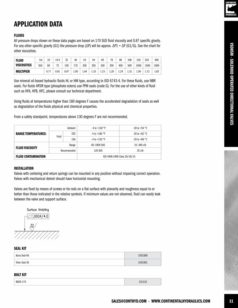
APPLICATION DATAFLUIDS All pressure drops shown on these data pages are based on 170 SUS fluid viscosity and 0.87 specific gravity. For any other specific gravity (G1) the pressure drop (∆P) will be approx. ∆P1 = ∆P (G1/G). See the chart for other viscosities.
Use mineral oil-based hydraulic fluids HL or HM type, according to ISO 6743-4. For these fluids, use NBR seals. For fluids HFDR type (phosphate esters) use FPM seals (code G). For the use of other kinds of fluid such as HFA, HFB, HFC, please consult our technical department.
Using fluids at temperatures higher than 180 degrees F causes the accelerated degradation of seals as well as degradation of the fluids physical and chemical properties.
From a safety standpoint, temperatures above 130 degrees F are not recommended.
FLUIDVISCOSITIES
Cst 10 14.5 32 36 43 54 65 76 86 108 216 324 400
SUS 60 75 150 170 200 250 300 350 400 500 1000 1500 1900
MULTIPIER 0.77 0.81 0.97 1.00 1.04 1.10 1.15 1.20 1.24 1.31 1.56 1.72 1.83
INSTALLATIONValves with centering and return springs can be mounted in any position without impairing correct operation. Valves with mechanical detent should have horizontal mounting.
Valves are fixed by means of screws or tie rods on a flat surface with planarity and roughness equal to or better than those indicated in the relative symbols. If minimum values are not observed, fluid can easily leak between the valve and support surface.
RANGE TEMPERATURES:
Ambient - 4 to +130 °F -20 to +54 °C
FluidSTD - 4 to +180 °F -20 to +82 °C
CSA - 4 to +150 °F -20 to +66 °C
FLUID VISCOSITYRange 60 -1900 SUS 10 - 400 cSt
Recommended 120 SUS 25 cSt
FLUID CONTAMINATION ISO 4406:1999 Class 20/18/15
SEAL KIT
BOLT KIT
Buna Seal Kit 1015300
Viton Seal Sit 1015301
BD05-175 131110
VSD0
5M -
SOLE
NOID
OPE
RATE
D DI
RECT
IONA
L VAL
VES
FORM NO. 1015299. REV. 09/2013. © 2012 CONTINENTAL HYDRAULICS. ALL RIGHTS RESERVED. PRODUCT SPECIFICATIONS AND APPEARANCE ARE SUBJECT TO CHANGE WITHOUT NOTICE.
ABOUT CONTINENTAL HYDRAULICSRugged, durable, high-performance, efcient—the reason Continental Hydraulics’ products are used in some of the most challenging applications across the globe. With a commitment to quality customer
support and innovative engineering, Continental’s pumps, valves, power units, mobile and custom products deliver what the markets demand. Continental has been serving the food production, brick
and block, wood products, automotive and machine tool industries since 1962. Learn how our products survive some of the most harsh environments.
[email protected] WEST 123RD STREET • SAVAGE, MN 55378-1299 / PH: 952.895.6400 / FAX: 952.895.6444 / WWW.CONTINENTALHYDRAULICS.COM
VSD*HL-*-KD2 - HAZARDOUS LOCATION, SOLENOID, DIRECT & PILOT OPERATED VALVES
5505 WEST 123RD STREET • SAVAGE, MN 55378-1299 / PH: 952.895.6400 / WWW.CONTINENTALHYDRAULICS.COM
CONTINENTAL HYDRAULICS
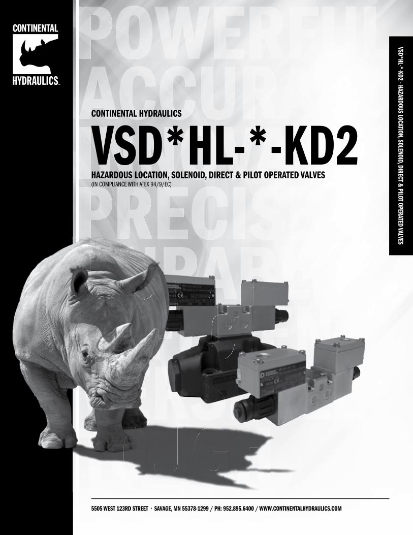
VSD*HL-*-KD2HAZARDOUS LOCATION, SOLENOID, DIRECT & PILOT OPERATED VALVES(IN COMPLIANCE WITH ATEX 94/9/EC)
2 WWW.CONTINENTALHYDRAULICS.COM - [email protected]
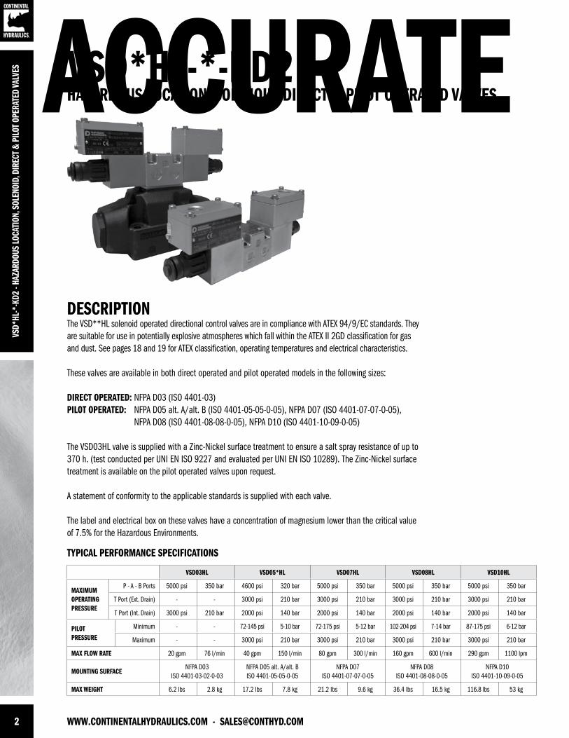
DESCRIPTIONThe VSD**HL solenoid operated directional control valves are in compliance with ATEX 94/9/EC standards. They are suitable for use in potentially explosive atmospheres which fall within the ATEX II 2GD classification for gas and dust. See pages 18 and 19 for ATEX classification, operating temperatures and electrical characteristics.
These valves are available in both direct operated and pilot operated models in the following sizes:
DIRECT OPERATED: NFPA D03 (ISO 4401-03)PILOT OPERATED: NFPA D05 alt. A/alt. B (ISO 4401-05-05-0-05), NFPA D07 (ISO 4401-07-07-0-05), NFPA D08 (ISO 4401-08-08-0-05), NFPA D10 (ISO 4401-10-09-0-05)
The VSD03HL valve is supplied with a Zinc-Nickel surface treatment to ensure a salt spray resistance of up to 370 h. (test conducted per UNI EN ISO 9227 and evaluated per UNI EN ISO 10289). The Zinc-Nickel surface treatment is available on the pilot operated valves upon request.
A statement of conformity to the applicable standards is supplied with each valve.
The label and electrical box on these valves have a concentration of magnesium lower than the critical value of 7.5% for the Hazardous Environments.
ACCURATEVS
D*HL
-*-K
D2 -
HAZA
RDOU
S LO
CATI
ON, S
OLEN
OID,
DIR
ECT &
PIL
OT O
PERA
TED
VALV
ES VSD*HL-*-KD2HAZARDOUS LOCATION, SOLENOID, DIRECT & PILOT OPERATED VALVES
TYPICAL PERFORMANCE SPECIFICATIONS
VSD03HL VSD05*HL VSD07HL VSD08HL VSD10HL
MAXIMUM OPERATINGPRESSURE
P - A - B Ports 5000 psi 350 bar 4600 psi 320 bar 5000 psi 350 bar 5000 psi 350 bar 5000 psi 350 bar
T Port (Ext. Drain) - - 3000 psi 210 bar 3000 psi 210 bar 3000 psi 210 bar 3000 psi 210 bar
T Port (Int. Drain) 3000 psi 210 bar 2000 psi 140 bar 2000 psi 140 bar 2000 psi 140 bar 2000 psi 140 bar
PILOTPRESSURE
Minimum - - 72-145 psi 5-10 bar 72-175 psi 5-12 bar 102-204 psi 7-14 bar 87-175 psi 6-12 bar
Maximum - - 3000 psi 210 bar 3000 psi 210 bar 3000 psi 210 bar 3000 psi 210 bar
MAX FLOW RATE 20 gpm 76 l/min 40 gpm 150 l/min 80 gpm 300 l/min 160 gpm 600 l/min 290 gpm 1100 lpm
MOUNTING SURFACENFPA D03
ISO 4401-03-02-0-03NFPA D05 alt. A/alt. BISO 4401-05-05-0-05
NFPA D07ISO 4401-07-07-0-05
NFPA D08ISO 4401-08-08-0-05
NFPA D10ISO 4401-10-09-0-05
MAX WEIGHT 6.2 lbs 2.8 kg 17.2 lbs 7.8 kg 21.2 lbs 9.6 kg 36.4 lbs 16.5 kg 116.8 lbs 53 kg
[email protected] - WWW.CONTINENTALHYDRAULICS.COM 3
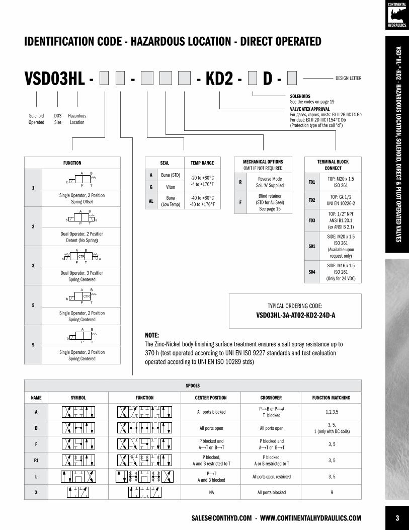
VSD03HL - - KD2 - D --
TYPICAL ORDERING CODE:
VSD03HL-3A-AT02-KD2-24D-A
IDENTIFICATION CODE - HAZARDOUS LOCATION - DIRECT OPERATED
DESIGN LETTER
SolenoidOperated
D03Size
HazardousLocation
VSD*HL-*-KD2 - HAZARDOUS LOCATION, SOLENOID, DIRECT & PILOT OPERATED VALVES
FUNCTION
1Single Operator, 2 Position
Spring Offset
2Dual Operator, 2 Position
Detent (No Spring)
3Dual Operator, 3 Position
Spring Centered
5
Single Operator, 2 PositionSpring Centered
9Single Operator, 2 Position
Spring Centered
NOTE:The Zinc-Nickel body finishing surface treatment ensures a salt spray resistance up to 370 h (test operated according to UNI EN ISO 9227 standards and test evaluation operated according to UNI EN ISO 10289 stds)
SPOOLS
NAME SYMBOL FUNCTION CENTER POSITION CROSSOVER FUNCTION MATCHING
A All ports blockedP→B or P→A
T blocked1,2,3,5
B All ports open All ports open3, 5,
1 (only with DC coils)
FP blocked and A→T or B→T
P blocked and A→T or B→T
3, 5
F1P blocked,
A and B restricted to TP blocked,
A or B restricted to T3, 5
LP→T
A and B blockedAll ports open, restricted 3, 5
X NA All ports blocked 9
SEAL TEMP RANGE
A Buna (STD) -20 to +80°C-4 to +176°FG Viton
ALBuna
(Low Temp)-40 to +80°C-40 to +176°F
MECHANICAL OPTIONSOMIT IF NOT REQUIRED
RReverse Mode
Sol. ‘A’ Supplied
FBlind retainer
(STD for AL Seal) See page 15
TERMINAL BLOCKCONNECT
T01TOP: M20 x 1.5
ISO 261
T02TOP: Gk 1/2
UNI EN 10226-2
T03TOP: 1/2” NPTANSI B1.20.1
(ex ANSI B 2.1)
S01
SIDE: M20 x 1.5ISO 261
(Available upon request only)
S04SIDE: M16 x 1.5
ISO 261(Only for 24 VDC)
SOLENOIDSSee the codes on page 19VALVE ATEX APPROVALFor gases, vapors, mists: EX II 2G IIC T4 GbFor dust: EX II 2D IIIC T154°C Db(Protection type of the coil “d”)
4 WWW.CONTINENTALHYDRAULICS.COM - [email protected]
VSD*
HL-*
-KD2
- HA
ZARD
OUS
LOCA
TION
, SOL
ENOI
D, D
IREC
T & P
ILOT
OPE
RATE
D VA
LVES
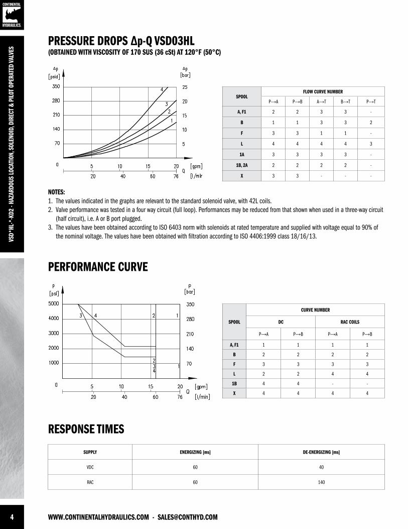
NOTES:1. The values indicated in the graphs are relevant to the standard solenoid valve, with 42L coils. 2. Valve performance was tested in a four way circuit (full loop). Performances may be reduced from that shown when used in a three-way circuit (half circuit), i.e. A or B port plugged.3. The values have been obtained according to ISO 6403 norm with solenoids at rated temperature and supplied with voltage equal to 90% of the nominal voltage. The values have been obtained with filtration according to ISO 4406:1999 class 18/16/13.
SPOOL
CURVE NUMBER
DC RAC COILS
P→A P→B P→A P→B
A, F1 1 1 1 1
B 2 2 2 2
F 3 3 3 3
L 2 2 4 4
1B 4 4 - -
X 4 4 4 4
SPOOLFLOW CURVE NUMBER
P→A P→B A→T B→T P→T
A, F1 2 2 3 3 -
B 1 1 3 3 2
F 3 3 1 1 -
L 4 4 4 4 3
1A 3 3 3 3 -
1B, 2A 2 2 2 2 -
X 3 3 - - -
PERFORMANCE CURVE
RESPONSE TIMES
PRESSURE DROPS ∆p-Q VSD03HL(OBTAINED WITH VISCOSITY OF 170 SUS (36 cSt) AT 120°F (50°C)
SUPPLY ENERGIZING [ms] DE-ENERGIZING [ms]
VDC 60 40
RAC 60 140
[email protected] - WWW.CONTINENTALHYDRAULICS.COM 5
VSD*HL-*-KD2 - HAZARDOUS LOCATION, SOLENOID, DIRECT & PILOT OPERATED VALVES
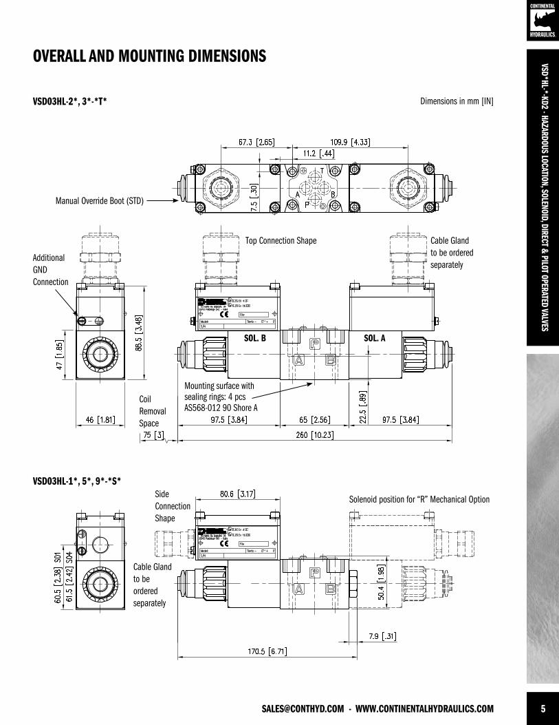
OVERALL AND MOUNTING DIMENSIONS
Dimensions in mm [IN]VSD03HL-2*, 3*-*T*
Manual Override Boot (STD)
AdditionalGNDConnection
Coil Removal Space
Mounting surface with sealing rings: 4 pcs AS568-012 90 Shore A
Top Connection Shape
SideConnection Shape
Solenoid position for “R” Mechanical Option
Cable Glandto be orderedseparately
SOL. ASOL. B
VSD03HL-1*, 5*, 9*-*S*
Cable Glandto beorderedseparately
6 WWW.CONTINENTALHYDRAULICS.COM - [email protected]
VSD*
HL-*
-KD2
- HA
ZARD
OUS
LOCA
TION
, SOL
ENOI
D, D
IREC
T & P
ILOT
OPE
RATE
D VA
LVES
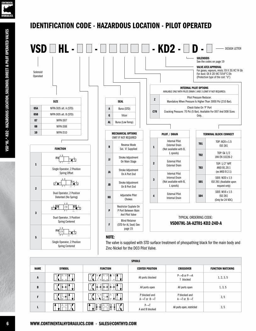
VSD HL - - KD2 - D --
TYPICAL ORDERING CODE:
VSD07HL-3A-A2T01-KD2-24D-A
IDENTIFICATION CODE - HAZARDOUS LOCATION - PILOT OPERATED
DESIGN LETTER
SolenoidOperated
FUNCTION
1Single Operator, 2 Position
Spring Offset
2Dual Operator, 2 Position
Detented (No Spring)
3Dual Operator, 3 Position
Spring Centered
5Single Operator, 2 Position
Spring Centered
NOTE:The valve is supplied with STD surface treatment of phospathing black for the main body and Zinc-Nickel for the D03 Pilot Valve.
SPOOLS
NAME SYMBOL FUNCTION CENTER POSITION CROSSOVER FUNCTION MATCHING
A All ports blockedP→B or P→A
T blocked1, 2, 3, 5
B All ports open All ports open 1, 3, 5
FP blocked and A→T or B→T
P blocked and A→T or B→T
3, 5
LP→T
A and B blockedAll ports open, restricted 3, 5
SEAL
A Buna (STD)
G Viton
AL Buna (Low Temp)
SIZE
05A NFPA D05 alt. A (STD)
05B NFPA D05 alt. B (STD)
07 NFPA D07
08 NFPA D08
10 NFPA D10 TERMINAL BLOCK CONNECT
T01TOP: M20 x 1.5
ISO 261
T02TOP: Gk 1/2
UNI EN 10226-2
T03TOP: 1/2” NPTANSI B1.20.1
(ex ANSI B 2.1)
S01SIDE: M20 x 1.5
ISO 261 (Available upon request only)
S04SIDE: M16 x 1.5
ISO 261(Only for 24 VDC)
SOLENOIDSSee the codes on page 19
VALVE ATEX APPROVALFor gases, vapours, mists: EX II 2G IIC T4 GbFor dust: EX II 2D IIIC T154°C Db(Protection type of the coil: “d”)
MECHANICAL OPTIONSOMIT IF NOT REQUIRED
RReverse Mode
Sol. ‘A’ Supplied
JJStroke Adjustment
On Main Stage
JAStroke Adjustment
On A Port End
JBStroke Adjustment
On B Port End
KKAdjustable Pilot
Chokes
PRestrictor Suplate On P Port Between Main
And Pilot Valve
FBlind Retainer
(STD for AL Seal) See page 15
PILOT / DRAIN
1
Internal Pilot External Drain
(Not available with B, L spools)
2External Pilot External Drain
3
Internal Pilot Internal Drain
(Not available with B, L spools)
4External Pilot Internal Drain
INTERNAL PILOT OPTIONSAVAILABLE ONLY WITH PILOT/DRAIN 1 AND 3 (OMIT IF NOT REQUIRED)
ZPilot Pressure Reducer.
Mandatory When Pressure Is Higher Than 3000 Psi (210 Bar).
C70Check Valve On ‘P’ Port
Cracking Pressure: 70 Psi (5 Bar). Available For D07 And D08 Sizes Only.
[email protected] - WWW.CONTINENTALHYDRAULICS.COM 7
VSD*HL-*-KD2 - HAZARDOUS LOCATION, SOLENOID, DIRECT & PILOT OPERATED VALVES
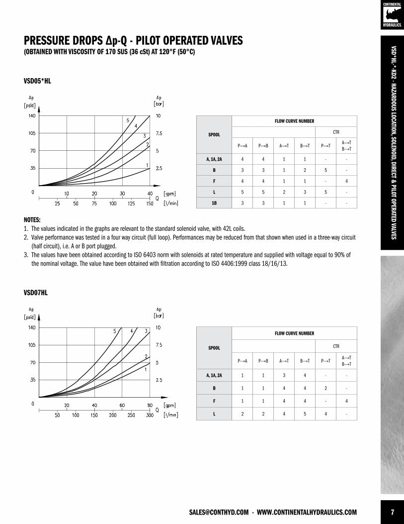
NOTES:1. The values indicated in the graphs are relevant to the standard solenoid valve, with 42L coils. 2. Valve performance was tested in a four way circuit (full loop). Performances may be reduced from that shown when used in a three-way circuit (half circuit), i.e. A or B port plugged.3. The values have been obtained according to ISO 6403 norm with solenoids at rated temperature and supplied with voltage equal to 90% of the nominal voltage. The value have been obtained with filtration according to ISO 4406:1999 class 18/16/13.
SPOOL
FLOW CURVE NUMBER
CTR
P→A P→B A→T B→T P→TA→T B→T
A, 1A, 2A 4 4 1 1 - -
B 3 3 1 2 5 -
F 4 4 1 1 - 4
L 5 5 2 3 5 -
1B 3 3 1 1 - -
SPOOL
FLOW CURVE NUMBER
CTR
P→A P→B A→T B→T P→TA→T B→T
A, 1A, 2A 1 1 3 4 - -
B 1 1 4 4 2 -
F 1 1 4 4 - 4
L 2 2 4 5 4 -
PRESSURE DROPS ∆p-Q - PILOT OPERATED VALVES(OBTAINED WITH VISCOSITY OF 170 SUS (36 cSt) AT 120°F (50°C)
VSD05*HL
VSD07HL
8 WWW.CONTINENTALHYDRAULICS.COM - [email protected]
VSD*
HL-*
-KD2
- HA
ZARD
OUS
LOCA
TION
, SOL
ENOI
D, D
IREC
T & P
ILOT
OPE
RATE
D VA
LVES
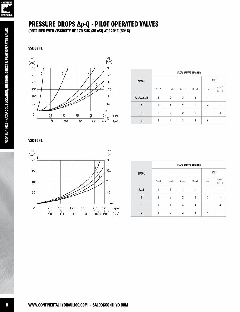
SPOOL
FLOW CURVE NUMBER
CTR
P→A P→B A→T B→T P→TA→T B→T
A, 1A, 2A, 1B 2 2 3 3 - -
B 1 1 2 1 4 -
F 2 2 2 1 - 4
L 4 4 3 5 6 -
SPOOL
FLOW CURVE NUMBER
CTR
P→A P→B A→T B→T P→TA→T B→T
A, 1B 1 1 1 1 - -
B 2 2 2 2 3 -
F 1 1 4 4 - 4
L 2 2 2 2 4 -
PRESSURE DROPS ∆p-Q - PILOT OPERATED VALVES(OBTAINED WITH VISCOSITY OF 170 SUS (36 cSt) AT 120°F (50°C)
VSD08HL
VSD10HL
[email protected] - WWW.CONTINENTALHYDRAULICS.COM 9
VSD*HL-*-KD2 - HAZARDOUS LOCATION, SOLENOID, DIRECT & PILOT OPERATED VALVES
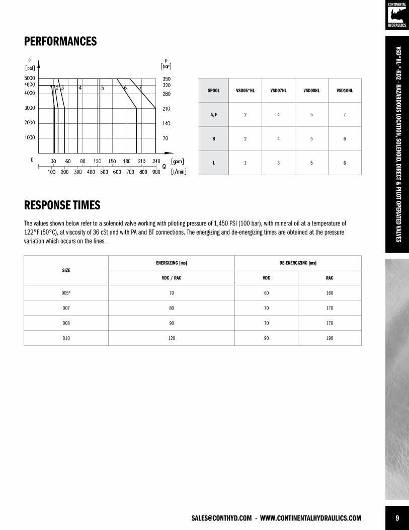
SPOOL VSD05*HL VSD07HL VSD08HL VSD10HL
A, F 2 4 5 7
B 2 4 5 6
L 1 3 5 6
PERFORMANCES
RESPONSE TIMES
SIZEENERGIZING [ms] DE-ENERGIZING [ms]
VDC / RAC VDC RAC
D05* 70 60 160
D07 80 70 170
D08 90 70 170
D10 120 90 190
The values shown below refer to a solenoid valve working with piloting pressure of 1,450 PSI (100 bar), with mineral oil at a temperature of 122°F (50°C), at viscosity of 36 cSt and with PA and BT connections. The energizing and de-energizing times are obtained at the pressure variation which occurs on the lines.
10 WWW.CONTINENTALHYDRAULICS.COM - [email protected]
VSD*
HL-*
-KD2
- HA
ZARD
OUS
LOCA
TION
, SOL
ENOI
D, D
IREC
T & P
ILOT
OPE
RATE
D VA
LVES
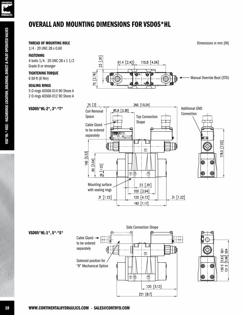
THREAD OF MOUNTING HOLE 1/4 - 20 UNC-2B x 0.60
FASTENING4 bolts 1/4 - 20 UNC-2B x 1 1/2 Grade 8 or stronger
TIGHTENING TORQUE6 lbf-ft (8 Nm)
SEALING RINGS5 O-rings AS568-014 90 Shore A2 O-rings AS568-012 90 Shore A
OVERALL AND MOUNTING DIMENSIONS FOR VSD05*HL
Dimensions in mm [IN]
VSD05*HL-2*, 3*-*T*
VSD05*HL-1*, 5*-*S*
Manual Override Boot (STD)
Additional GNDConnection
Top ConnectionShape
Side Connection Shape
Coil RemovalSpace
Cable Glandto be orderedseparately
Mounting surface with sealing rings
Cable Glandto be orderedseparately
Solenoid position for “R” Mechanical Option
[email protected] - WWW.CONTINENTALHYDRAULICS.COM 11
VSD*HL-*-KD2 - HAZARDOUS LOCATION, SOLENOID, DIRECT & PILOT OPERATED VALVES
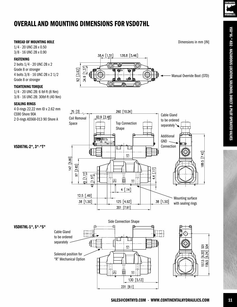
OVERALL AND MOUNTING DIMENSIONS FOR VSD07HL
Dimensions in mm [IN]
VSD07HL-2*, 3*-*T*
VSD07HL-1*, 5*-*S*
Manual Override Boot (STD)
Additional GNDConnection
Top ConnectionShape
Side Connection Shape
Coil RemovalSpace
Cable Glandto be orderedseparately
Cable Glandto be orderedseparately
Solenoid position for “R” Mechanical Option
THREAD OF MOUNTING HOLE 1/4 - 20 UNC-2B x 0.503/8 - 16 UNC-2B x 0.90
FASTENING2 bolts 1/4 - 20 UNC-2B x 2Grade 8 or stronger4 bolts 3/8 - 16 UNC-2B x 2 1/2 Grade 8 or stronger
TIGHTENING TORQUE1/4 - 20 UNC-2B: 6 lbf-ft (8 Nm)3/8 - 16 UNC-2B: 30lbf-ft (40 Nm)
SEALING RINGS4 O-rings 22.22 mm ID x 2.62 mmCS90 Shore 90A2 O-rings AS568-013 90 Shore A
Mounting surface with sealing rings
12 WWW.CONTINENTALHYDRAULICS.COM - [email protected]
VSD*
HL-*
-KD2
- HA
ZARD
OUS
LOCA
TION
, SOL
ENOI
D, D
IREC
T & P
ILOT
OPE
RATE
D VA
LVES
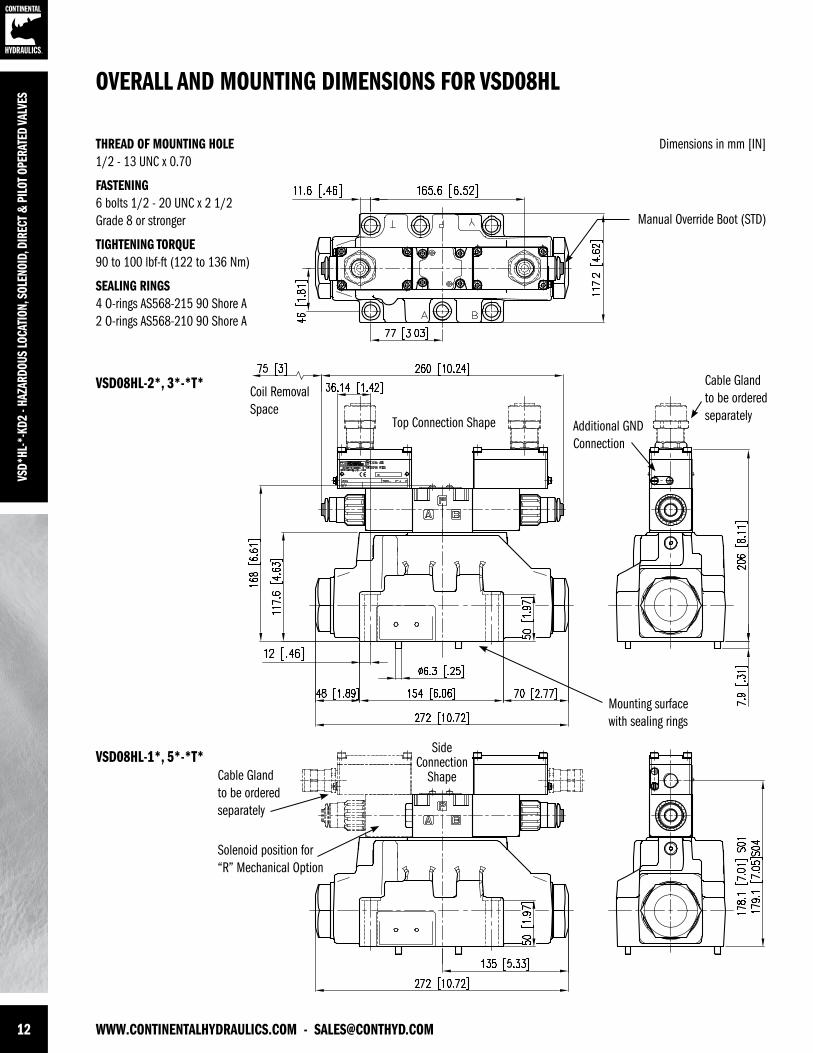
THREAD OF MOUNTING HOLE 1/2 - 13 UNC x 0.70
FASTENING6 bolts 1/2 - 20 UNC x 2 1/2 Grade 8 or stronger
TIGHTENING TORQUE90 to 100 lbf-ft (122 to 136 Nm)
SEALING RINGS4 O-rings AS568-215 90 Shore A2 O-rings AS568-210 90 Shore A
OVERALL AND MOUNTING DIMENSIONS FOR VSD08HL
Dimensions in mm [IN]
VSD08HL-2*, 3*-*T*
VSD08HL-1*, 5*-*T*
Manual Override Boot (STD)
SideConnection
ShapeCable Glandto be orderedseparately
Solenoid position for “R” Mechanical Option
Mounting surface with sealing rings
Additional GNDConnection
Top Connection Shape
Coil RemovalSpace
Cable Glandto be orderedseparately
[email protected] - WWW.CONTINENTALHYDRAULICS.COM 13
VSD*HL-*-KD2 - HAZARDOUS LOCATION, SOLENOID, DIRECT & PILOT OPERATED VALVES
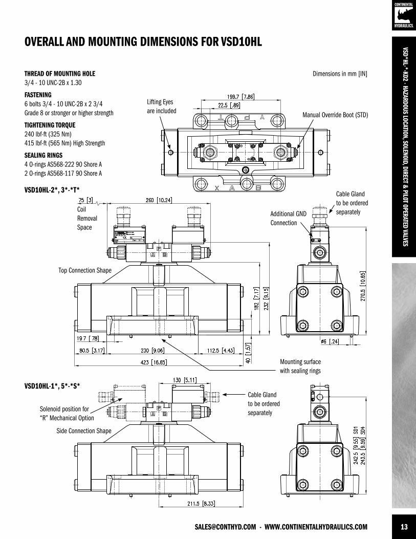
THREAD OF MOUNTING HOLE 3/4 - 10 UNC-2B x 1.30
FASTENING6 bolts 3/4 - 10 UNC-2B x 2 3/4 Grade 8 or stronger or higher strength
TIGHTENING TORQUE240 lbf-ft (325 Nm)415 lbf-ft (565 Nm) High Strength
SEALING RINGS4 O-rings AS568-222 90 Shore A2 O-rings AS568-117 90 Shore A
OVERALL AND MOUNTING DIMENSIONS FOR VSD10HL
Dimensions in mm [IN]
Solenoid position for “R” Mechanical Option
Mounting surface with sealing rings
Top Connection Shape
Side Connection Shape
CoilRemovalSpace
VSD10HL-2*, 3*-*T*
VSD10HL-1*, 5*-*S*
Manual Override Boot (STD)
Lifting Eyesare included
Cable Glandto be orderedseparatelyAdditional GND
Connection
Cable Glandto be orderedseparately
14 WWW.CONTINENTALHYDRAULICS.COM - [email protected]
VSD*
HL-*
-KD2
- HA
ZARD
OUS
LOCA
TION
, SOL
ENOI
D, D
IREC
T & P
ILOT
OPE
RATE
D VA
LVES
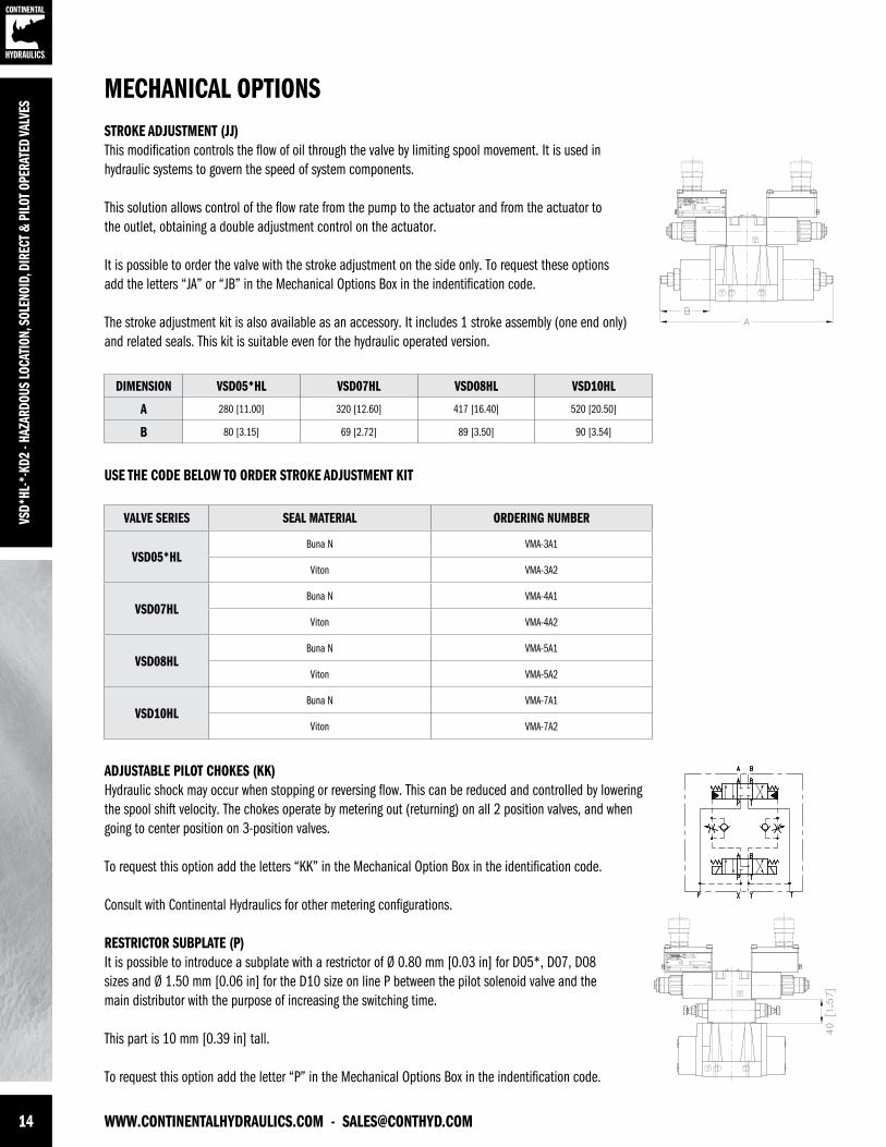
MECHANICAL OPTIONSSTROKE ADJUSTMENT (JJ)This modification controls the flow of oil through the valve by limiting spool movement. It is used in hydraulic systems to govern the speed of system components.
This solution allows control of the flow rate from the pump to the actuator and from the actuator to the outlet, obtaining a double adjustment control on the actuator.
It is possible to order the valve with the stroke adjustment on the side only. To request these options add the letters “JA” or “JB” in the Mechanical Options Box in the indentification code.
The stroke adjustment kit is also available as an accessory. It includes 1 stroke assembly (one end only) and related seals. This kit is suitable even for the hydraulic operated version.
ADJUSTABLE PILOT CHOKES (KK)Hydraulic shock may occur when stopping or reversing flow. This can be reduced and controlled by lowering the spool shift velocity. The chokes operate by metering out (returning) on all 2 position valves, and when going to center position on 3-position valves.
To request this option add the letters “KK” in the Mechanical Option Box in the identification code.
Consult with Continental Hydraulics for other metering configurations.
RESTRICTOR SUBPLATE (P)It is possible to introduce a subplate with a restrictor of Ø 0.80 mm [0.03 in] for D05*, D07, D08 sizes and Ø 1.50 mm [0.06 in] for the D10 size on line P between the pilot solenoid valve and the main distributor with the purpose of increasing the switching time.
This part is 10 mm [0.39 in] tall.
To request this option add the letter “P” in the Mechanical Options Box in the indentification code.
USE THE CODE BELOW TO ORDER STROKE ADJUSTMENT KIT
DIMENSION VSD05*HL VSD07HL VSD08HL VSD10HL
A 280 [11.00] 320 [12.60] 417 [16.40] 520 [20.50]
B 80 [3.15] 69 [2.72] 89 [3.50] 90 [3.54]
VALVE SERIES SEAL MATERIAL ORDERING NUMBER
VSD05*HLBuna N VMA-3A1
Viton VMA-3A2
VSD07HLBuna N VMA-4A1
Viton VMA-4A2
VSD08HLBuna N VMA-5A1
Viton VMA-5A2
VSD10HLBuna N VMA-7A1
Viton VMA-7A2
[email protected] - WWW.CONTINENTALHYDRAULICS.COM 15
VSD*HL-*-KD2 - HAZARDOUS LOCATION, SOLENOID, DIRECT & PILOT OPERATED VALVES
MECHANICAL OPTIONS
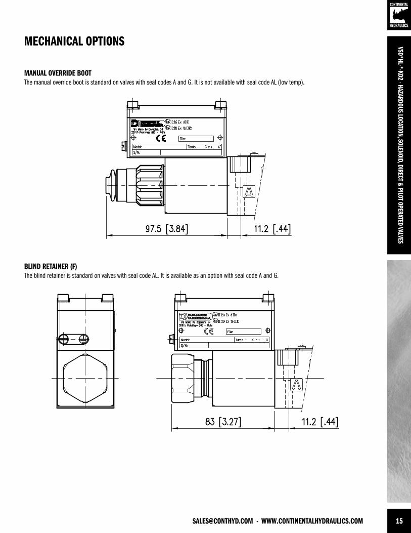
MANUAL OVERRIDE BOOTThe manual override boot is standard on valves with seal codes A and G. It is not available with seal code AL (low temp).
BLIND RETAINER (F)The blind retainer is standard on valves with seal code AL. It is available as an option with seal code A and G.
16 WWW.CONTINENTALHYDRAULICS.COM - [email protected]
VSD*
HL-*
-KD2
- HA
ZARD
OUS
LOCA
TION
, SOL
ENOI
D, D
IREC
T & P
ILOT
OPE
RATE
D VA
LVES
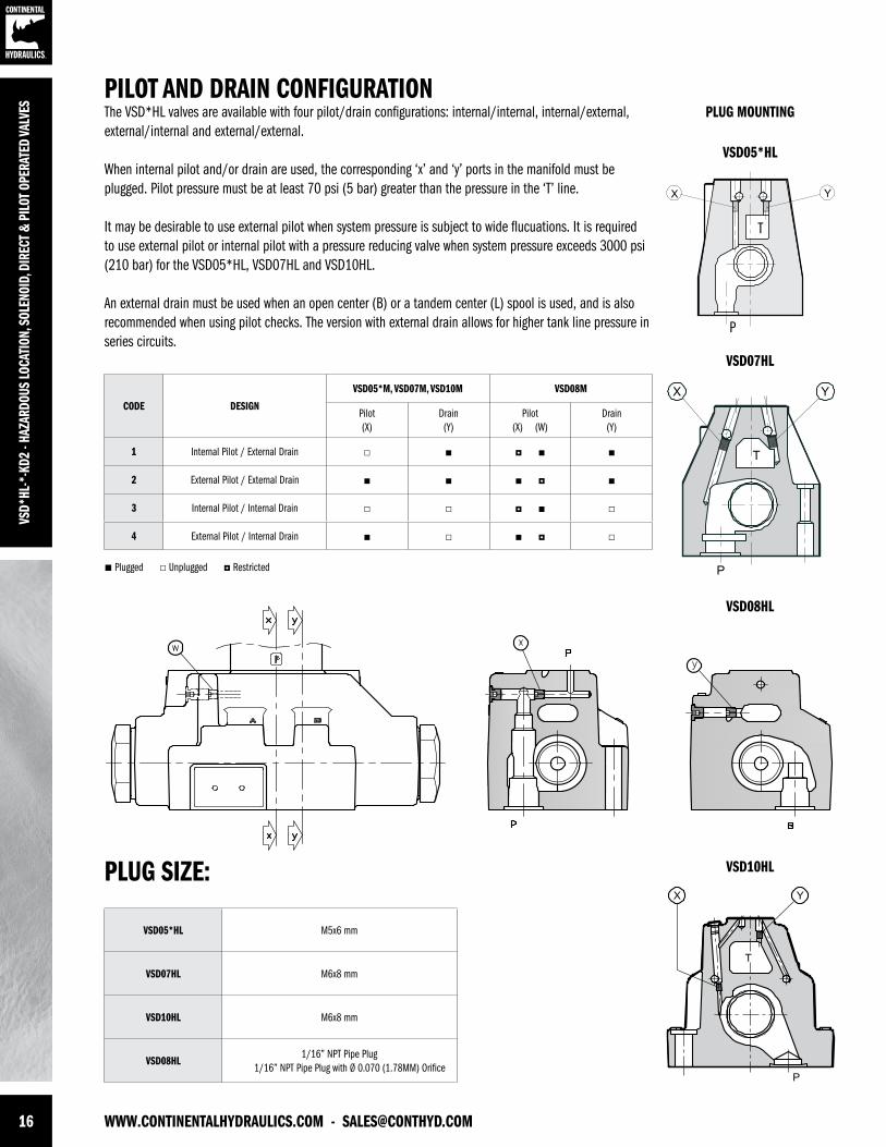
PILOT AND DRAIN CONFIGURATIONThe VSD*HL valves are available with four pilot/drain configurations: internal/internal, internal/external, external/internal and external/external.
When internal pilot and/or drain are used, the corresponding ‘x’ and ‘y’ ports in the manifold must be plugged. Pilot pressure must be at least 70 psi (5 bar) greater than the pressure in the ‘T’ line.
It may be desirable to use external pilot when system pressure is subject to wide flucuations. It is required to use external pilot or internal pilot with a pressure reducing valve when system pressure exceeds 3000 psi (210 bar) for the VSD05*HL, VSD07HL and VSD10HL.
An external drain must be used when an open center (B) or a tandem center (L) spool is used, and is also recommended when using pilot checks. The version with external drain allows for higher tank line pressure in series circuits.
PLUG MOUNTING
VSD05*HL
VSD07HL
PLUG SIZE:
CODE DESIGN
VSD05*M, VSD07M, VSD10M VSD08M
Pilot(X)
Drain(Y)
Pilot(X) (W)
Drain(Y)
1 Internal Pilot / External Drain
2 External Pilot / External Drain
3 Internal Pilot / Internal Drain
4 External Pilot / Internal Drain
VSD05*HL M5x6 mm
VSD07HL M6x8 mm
VSD10HL M6x8 mm
VSD08HL1/16” NPT Pipe Plug
1/16” NPT Pipe Plug with Ø 0.070 (1.78MM) Orifice
T
P
VSD08HL
VSD10HL
Plugged Unplugged Restricted
[email protected] - WWW.CONTINENTALHYDRAULICS.COM 17
VSD*HL-*-KD2 - HAZARDOUS LOCATION, SOLENOID, DIRECT & PILOT OPERATED VALVES
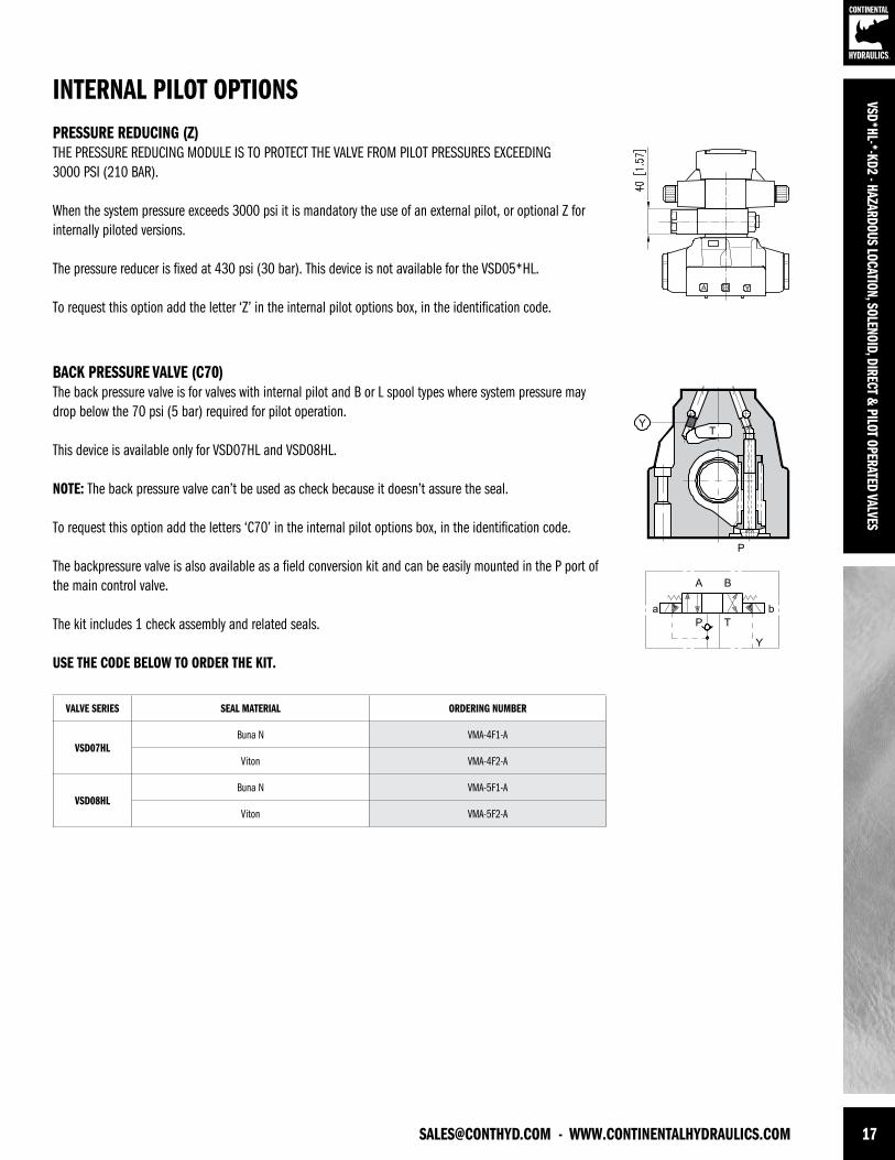
BACK PRESSURE VALVE (C70)The back pressure valve is for valves with internal pilot and B or L spool types where system pressure may drop below the 70 psi (5 bar) required for pilot operation.
This device is available only for VSD07HL and VSD08HL.
NOTE: The back pressure valve can’t be used as check because it doesn’t assure the seal.
To request this option add the letters ‘C70’ in the internal pilot options box, in the identification code.
The backpressure valve is also available as a field conversion kit and can be easily mounted in the P port of the main control valve.
The kit includes 1 check assembly and related seals.
USE THE CODE BELOW TO ORDER THE KIT.
PRESSURE REDUCING (Z)THE PRESSURE REDUCING MODULE IS TO PROTECT THE VALVE FROM PILOT PRESSURES EXCEEDING3000 PSI (210 BAR). When the system pressure exceeds 3000 psi it is mandatory the use of an external pilot, or optional Z for internally piloted versions.
The pressure reducer is fixed at 430 psi (30 bar). This device is not available for the VSD05*HL.
To request this option add the letter ‘Z’ in the internal pilot options box, in the identification code.
INTERNAL PILOT OPTIONS
VALVE SERIES SEAL MATERIAL ORDERING NUMBER
VSD07HLBuna N VMA-4F1-A
Viton VMA-4F2-A
VSD08HLBuna N VMA-5F1-A
Viton VMA-5F2-A
18 WWW.CONTINENTALHYDRAULICS.COM - [email protected]
VSD*
HL-*
-KD2
- HA
ZARD
OUS
LOCA
TION
, SOL
ENOI
D, D
IREC
T & P
ILOT
OPE
RATE
D VA
LVES
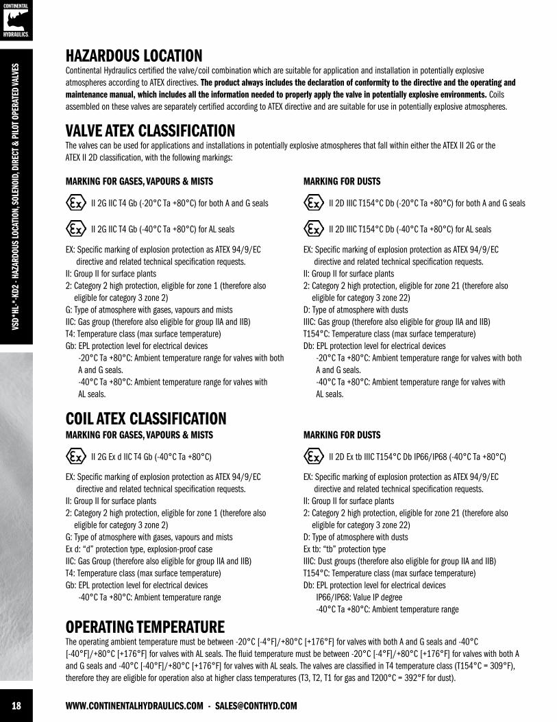
HAZARDOUS LOCATIONContinental Hydraulics certified the valve/coil combination which are suitable for application and installation in potentially explosive atmospheres according to ATEX directives. The product always includes the declaration of conformity to the directive and the operating and maintenance manual, which includes all the information needed to properly apply the valve in potentially explosive environments. Coils assembled on these valves are separately certified according to ATEX directive and are suitable for use in potentially explosive atmospheres.
OPERATING TEMPERATUREThe operating ambient temperature must be between -20°C [-4°F]/+80°C [+176°F] for valves with both A and G seals and -40°C [-40°F]/+80°C [+176°F] for valves with AL seals. The fluid temperature must be between -20°C [-4°F]/+80°C [+176°F] for valves with both A and G seals and -40°C [-40°F]/+80°C [+176°F] for valves with AL seals. The valves are classified in T4 temperature class (T154°C = 309°F), therefore they are eligible for operation also at higher class temperatures (T3, T2, T1 for gas and T200°C = 392°F for dust).
COIL ATEX CLASSIFICATION
EX: Specific marking of explosion protection as ATEX 94/9/EC directive and related technical specification requests.II: Group II for surface plants2: Category 2 high protection, eligible for zone 1 (therefore also eligible for category 3 zone 2)G: Type of atmosphere with gases, vapours and mistsEx d: “d” protection type, explosion-proof caseIIC: Gas Group (therefore also eligible for group IIA and IIB)T4: Temperature class (max surface temperature)Gb: EPL protection level for electrical devices -40°C Ta +80°C: Ambient temperature range
EX: Specific marking of explosion protection as ATEX 94/9/EC directive and related technical specification requests.II: Group II for surface plants2: Category 2 high protection, eligible for zone 21 (therefore also eligible for category 3 zone 22)D: Type of atmosphere with dustsEx tb: “tb” protection typeIIIC: Dust groups (therefore also eligible for group IIA and IIB)T154°C: Temperature class (max surface temperature)Db: EPL protection level for electrical devices IP66/IP68: Value IP degree -40°C Ta +80°C: Ambient temperature range
II 2G Ex d IIC T4 Gb (-40°C Ta +80°C)
MARKING FOR GASES, VAPOURS & MISTS
II 2D Ex tb IIIC T154°C Db IP66/IP68 (-40°C Ta +80°C)
MARKING FOR DUSTS
VALVE ATEX CLASSIFICATIONThe valves can be used for applications and installations in potentially explosive atmospheres that fall within either the ATEX II 2G or the ATEX II 2D classification, with the following markings:
EX: Specific marking of explosion protection as ATEX 94/9/EC directive and related technical specification requests.II: Group II for surface plants2: Category 2 high protection, eligible for zone 1 (therefore also eligible for category 3 zone 2)G: Type of atmosphere with gases, vapours and mistsIIC: Gas group (therefore also eligible for group IIA and IIB)T4: Temperature class (max surface temperature)Gb: EPL protection level for electrical devices -20°C Ta +80°C: Ambient temperature range for valves with both A and G seals. -40°C Ta +80°C: Ambient temperature range for valves with AL seals.
EX: Specific marking of explosion protection as ATEX 94/9/EC directive and related technical specification requests.II: Group II for surface plants2: Category 2 high protection, eligible for zone 21 (therefore also eligible for category 3 zone 22)D: Type of atmosphere with dustsIIIC: Gas group (therefore also eligible for group IIA and IIB)T154°C: Temperature class (max surface temperature)Db: EPL protection level for electrical devices -20°C Ta +80°C: Ambient temperature range for valves with both A and G seals. -40°C Ta +80°C: Ambient temperature range for valves with AL seals.
II 2G IIC T4 Gb (-20°C Ta +80°C) for both A and G seals II 2D IIIC T154°C Db (-20°C Ta +80°C) for both A and G seals
II 2G IIC T4 Gb (-40°C Ta +80°C) for AL seals II 2D IIIC T154°C Db (-40°C Ta +80°C) for AL seals
MARKING FOR GASES, VAPOURS & MISTS MARKING FOR DUSTS
[email protected] - WWW.CONTINENTALHYDRAULICS.COM 19
VSD*HL-*-KD2 - HAZARDOUS LOCATION, SOLENOID, DIRECT & PILOT OPERATED VALVES
VDC COILS
RECTIFIED COILS
SOLENOIDSListed below the types of solenoids available and the numbers to be added in the solenoid box on page 3 or 6.
COILCODE
VOLTAGE[VAC]
FREQUENCY[Hz]
RESISTENCE±5% [OHM]
HOLDINGCURRENT [A]
POWERCONSUMPTION [VA]
PRE-FUSE[A]
MAX VOLTAGEUPON SWITCH OFF [V]
R120120 60
489.60.21 25
0.30 -3110 50 0.19 21
R240240 60
2067.70.10 24
0.15 -3230 50 0.10 22.5
COILCODE
VOLTAGE±5% [VDC]
RESISTENCE±5% [OHM]
HOLDINGCURRENT [A]
POWERCONSUMPTION [VA]
PRE-FUSE[A]
MAX VOLTAGEUPON SWITCH OFF [V]
12 12 7.2 1.7 20 2.5 -49
24 24 28.7 0.83 20 1.25 -49
48 48 115 0.42 20 0.6 -81
110 110 549 0.2 22 0.3 -309
Upstream of each valve, an appropriate fuse (max 3 x In according to IEC 60127) or a protective motor switch with short-circuit and thermal instantaneous tripping, as short-circuit protection, must be connected. The cut-off power of the fuse must correspond or exceed the short-circuit current of the supply source. The fuse or protective motor must be placed outside the dangerous area or they must be protected with an explosion-proof covering.
In order to safeguard the electronic device to which the valve is connected, there is a protection circuit in the coil, that reduces voltage peaks, which can occur when inductances are switched off.
The charts above show the type of fuse recommended according to the nominal voltage of the valve and to the value of the voltage peaks reduction.
Recommended Upstream Fuse
Recommended Upstream Fuse
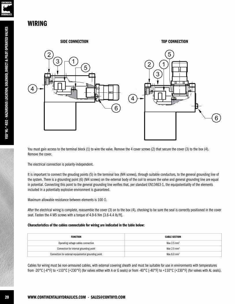
20 WWW.CONTINENTALHYDRAULICS.COM - [email protected]
VSD*
HL-*
-KD2
- HA
ZARD
OUS
LOCA
TION
, SOL
ENOI
D, D
IREC
T & P
ILOT
OPE
RATE
D VA
LVES
WIRING
SIDE CONNECTION TOP CONNECTION
You must gain access to the terminal block (1) to wire the valve. Remove the 4 cover screws (2) that secure the cover (3) to the box (4). Remove the cover.
The electrical connection is polarity-independent.
It is important to connect the grouding points (5) in the terminal box (M4 screws), through suitable conductors, to the general grounding line of the system. There is a grounding point (6) (M4 screws) on the external body of the coil to ensure the valve and general grounding line are equal in potential. Connecting this point to the general grounding line verifies that, per standard EN13463-1, the equipotentiality of the elements included in a potentially explosive environment is guaranteed.
Maximum allowable resistance between elements is 100 Ω.
After the electrical wiring is complete, reassemble the cover (3) on to the box (4), checking to be sure the seal is correctly positioned in the cover seat. Fasten the 4 M5 screws with a torque of 4.9-6 Nm [3.6-4.4 lb/ft].
Characteristics of the cables connectable for wiring are indicated in the table below:
Cables for wiring must be non-armoured cables, with external covering sheath and must be suitable for use in environments with temperatures from -20°C [-4°F] to +110°C [+230°F] (for valves either with A or G seals) or from -40°C [-40°F] to +110°C [+230°F] (for valves with AL seals).
FUNCTION CABLE SECTION
Operating voltage cables connection Max 2.5 mm2
Connection for internal grounding point Max 2.5 mm2
Connection for external equipotential grounding point Max 6.0 mm2
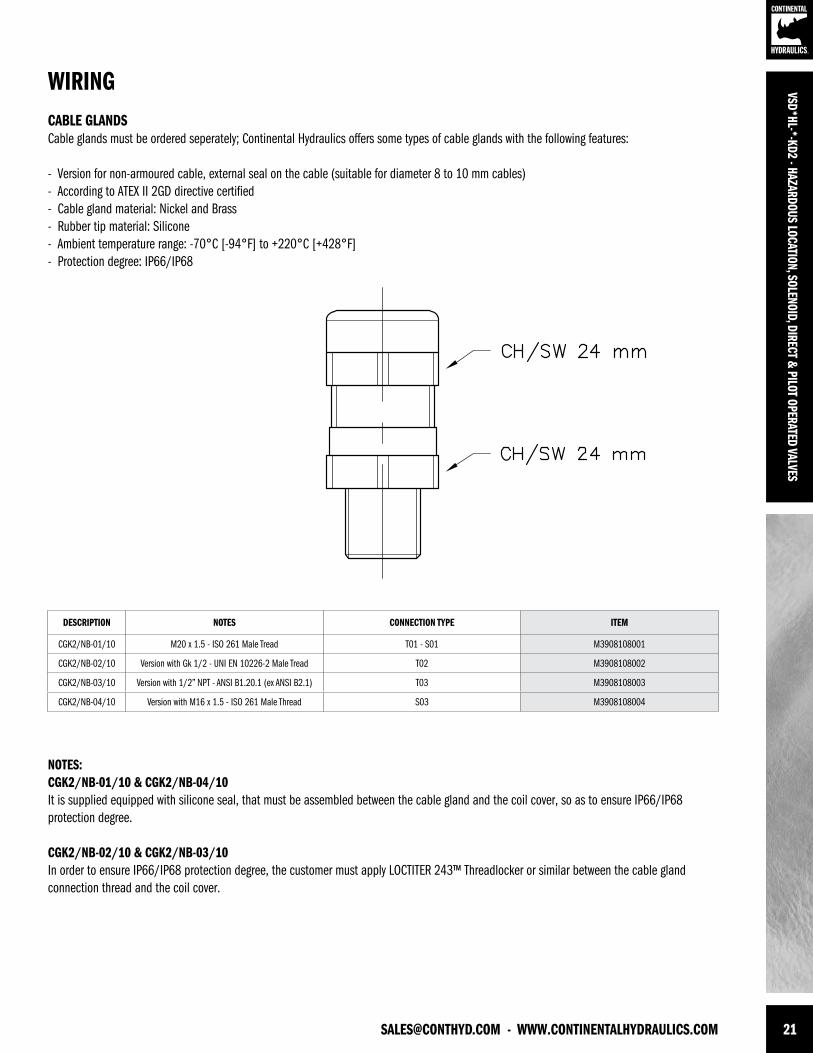
[email protected] - WWW.CONTINENTALHYDRAULICS.COM 21
VSD*HL-*-KD2 - HAZARDOUS LOCATION, SOLENOID, DIRECT & PILOT OPERATED VALVES
NOTES:CGK2/NB-01/10 & CGK2/NB-04/10It is supplied equipped with silicone seal, that must be assembled between the cable gland and the coil cover, so as to ensure IP66/IP68 protection degree.
CGK2/NB-02/10 & CGK2/NB-03/10In order to ensure IP66/IP68 protection degree, the customer must apply LOCTITER 243™ Threadlocker or similar between the cable gland connection thread and the coil cover.
CABLE GLANDSCable glands must be ordered seperately; Continental Hydraulics offers some types of cable glands with the following features: - Version for non-armoured cable, external seal on the cable (suitable for diameter 8 to 10 mm cables)- According to ATEX II 2GD directive certified- Cable gland material: Nickel and Brass- Rubber tip material: Silicone- Ambient temperature range: -70°C [-94°F] to +220°C [+428°F]- Protection degree: IP66/IP68
WIRING
DESCRIPTION NOTES CONNECTION TYPE ITEM
CGK2/NB-01/10 M20 x 1.5 - ISO 261 Male Tread T01 - S01 M3908108001
CGK2/NB-02/10 Version with Gk 1/2 - UNI EN 10226-2 Male Tread T02 M3908108002
CGK2/NB-03/10 Version with 1/2” NPT - ANSI B1.20.1 (ex ANSI B2.1) T03 M3908108003
CGK2/NB-04/10 Version with M16 x 1.5 - ISO 261 Male Thread S03 M3908108004
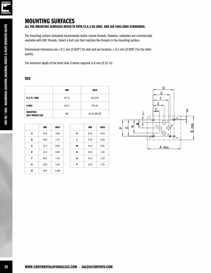
22 WWW.CONTINENTALHYDRAULICS.COM - [email protected]
VSD*
HL-*
-KD2
- HA
ZARD
OUS
LOCA
TION
, SOL
ENOI
D, D
IREC
T & P
ILOT
OPE
RATE
D VA
LVES
MOUNTING SURFACESALL THE MOUNTING SURFACES REFER TO NFPA T3.5.1 R2-2002 AND ISO 4401:2005 STANDARDS.
The mounting surface standards recommends metric coarse threads. However, subplates are commercially available with UNC threads. Select a bolt size that matches the threads in the mounting surface.
Dimensional tolerances are ± 0.1 mm (0.004”) for bolt and pin location; ± 0.2 mm (0.008”) for the other quotes.
The minimum depth of the blind hole G where required is 8 mm (0.31 in).
MM INCH
P, A, B, T MAX Ø 7.0 Ø 0.276
G MAX Ø 4.0 Ø 0.16
MOUNTINGBOLT THREAD SIZE
M5 10-24 UNC 2B
MM INCH
A 51.0 2.00
B 43.0 1.70
C 12.7 0.50
E 21.5 0.85
F 30.2 1.19
G 33.0 1.30
H 40.5 1.594
MM INCH
K 0.75 0.03
L 5.10 0.20
M 15.5 0.61
N 25.9 1.02
O 31.0 1.22
P 31.8 1.25
D03
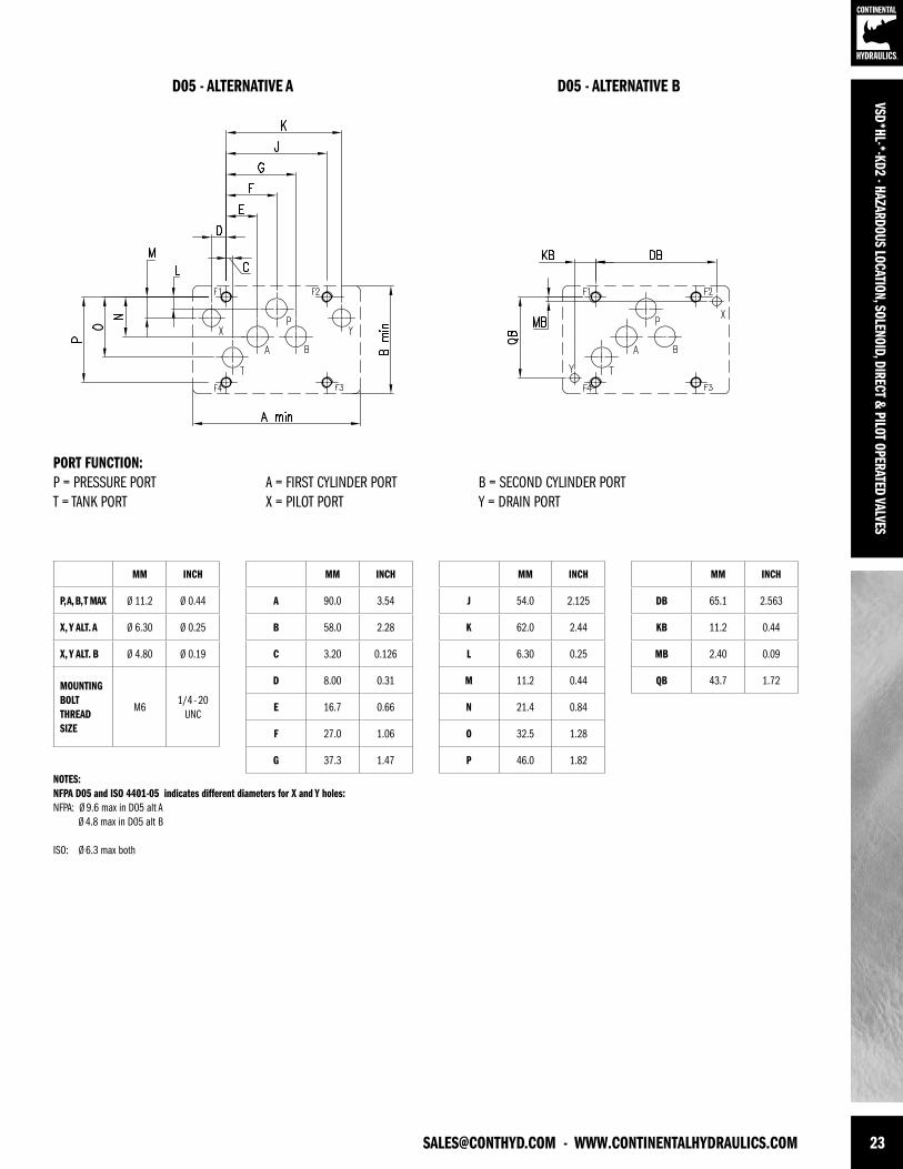
[email protected] - WWW.CONTINENTALHYDRAULICS.COM 23
VSD*HL-*-KD2 - HAZARDOUS LOCATION, SOLENOID, DIRECT & PILOT OPERATED VALVES
PORT FUNCTION:P = PRESSURE PORT A = FIRST CYLINDER PORT B = SECOND CYLINDER PORTT = TANK PORT X = PILOT PORT Y = DRAIN PORT
NOTES:NFPA D05 and ISO 4401-05 indicates different diameters for X and Y holes:NFPA: Ø 9.6 max in D05 alt A Ø 4.8 max in D05 alt B
ISO: Ø 6.3 max both
MM INCH
P, A, B, T MAX Ø 11.2 Ø 0.44
X, Y ALT. A Ø 6.30 Ø 0.25
X, Y ALT. B Ø 4.80 Ø 0.19
MOUNTINGBOLT THREAD SIZE
M61/4 - 20
UNC
MM INCH
A 90.0 3.54
B 58.0 2.28
C 3.20 0.126
D 8.00 0.31
E 16.7 0.66
F 27.0 1.06
G 37.3 1.47
MM INCH
J 54.0 2.125
K 62.0 2.44
L 6.30 0.25
M 11.2 0.44
N 21.4 0.84
O 32.5 1.28
P 46.0 1.82
MM INCH
DB 65.1 2.563
KB 11.2 0.44
MB 2.40 0.09
QB 43.7 1.72
D05 - ALTERNATIVE A D05 - ALTERNATIVE B
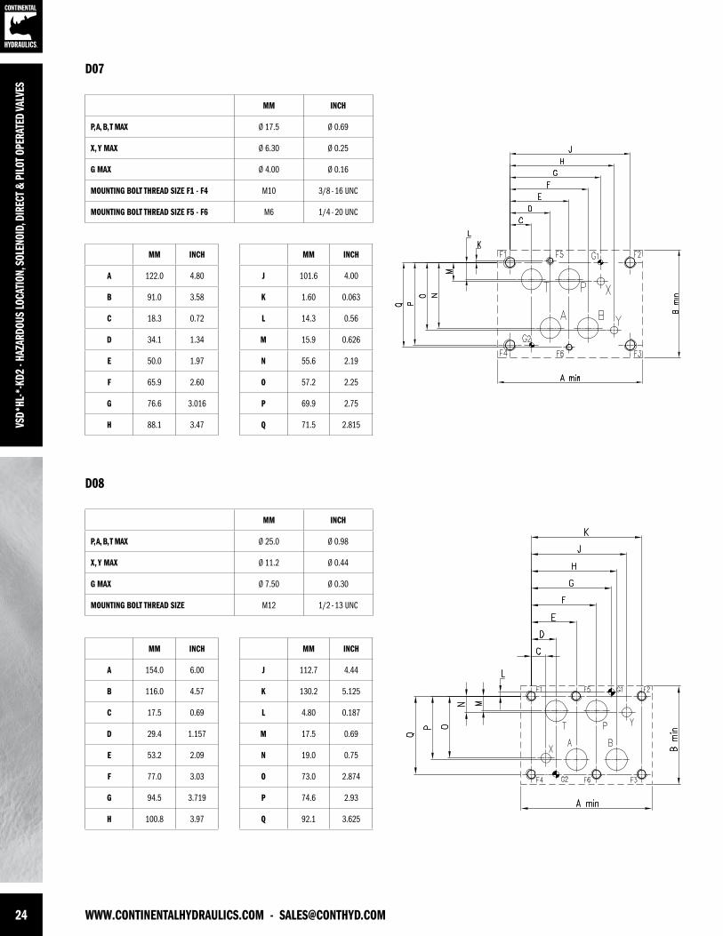
24 WWW.CONTINENTALHYDRAULICS.COM - [email protected]
VSD*
HL-*
-KD2
- HA
ZARD
OUS
LOCA
TION
, SOL
ENOI
D, D
IREC
T & P
ILOT
OPE
RATE
D VA
LVES
MM INCH
P, A, B, T MAX Ø 17.5 Ø 0.69
X, Y MAX Ø 6.30 Ø 0.25
G MAX Ø 4.00 Ø 0.16
MOUNTING BOLT THREAD SIZE F1 - F4 M10 3/8 - 16 UNC
MOUNTING BOLT THREAD SIZE F5 - F6 M6 1/4 - 20 UNC
MM INCH
A 122.0 4.80
B 91.0 3.58
C 18.3 0.72
D 34.1 1.34
E 50.0 1.97
F 65.9 2.60
G 76.6 3.016
H 88.1 3.47
MM INCH
J 101.6 4.00
K 1.60 0.063
L 14.3 0.56
M 15.9 0.626
N 55.6 2.19
O 57.2 2.25
P 69.9 2.75
Q 71.5 2.815
MM INCH
P, A, B, T MAX Ø 25.0 Ø 0.98
X, Y MAX Ø 11.2 Ø 0.44
G MAX Ø 7.50 Ø 0.30
MOUNTING BOLT THREAD SIZE M12 1/2 - 13 UNC
MM INCH
A 154.0 6.00
B 116.0 4.57
C 17.5 0.69
D 29.4 1.157
E 53.2 2.09
F 77.0 3.03
G 94.5 3.719
H 100.8 3.97
MM INCH
J 112.7 4.44
K 130.2 5.125
L 4.80 0.187
M 17.5 0.69
N 19.0 0.75
O 73.0 2.874
P 74.6 2.93
Q 92.1 3.625
D07
D08
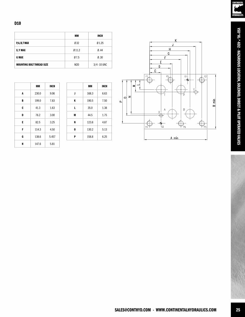
[email protected] - WWW.CONTINENTALHYDRAULICS.COM 25
VSD*HL-*-KD2 - HAZARDOUS LOCATION, SOLENOID, DIRECT & PILOT OPERATED VALVES
MM INCH
P, A, B, T MAX Ø 32 Ø 1.25
X, Y MAX Ø 11.2 Ø .44
G MAX Ø 7.5 Ø .30
MOUNTING BOLT THREAD SIZE M20 3/4 - 10 UNC
MM INCH
A 230.0 9.06
B 199.0 7.83
C 41.3 1.63
D 76.2 3.00
E 82.5 3.25
F 114.3 4.50
G 138.6 5.457
H 147.6 5.81
MM INCH
J 168.3 6.63
K 190.5 7.50
L 35.0 1.38
M 44.5 1.75
N 123.8 4.87
O 130.2 5.13
P 158.8 6.25
D10
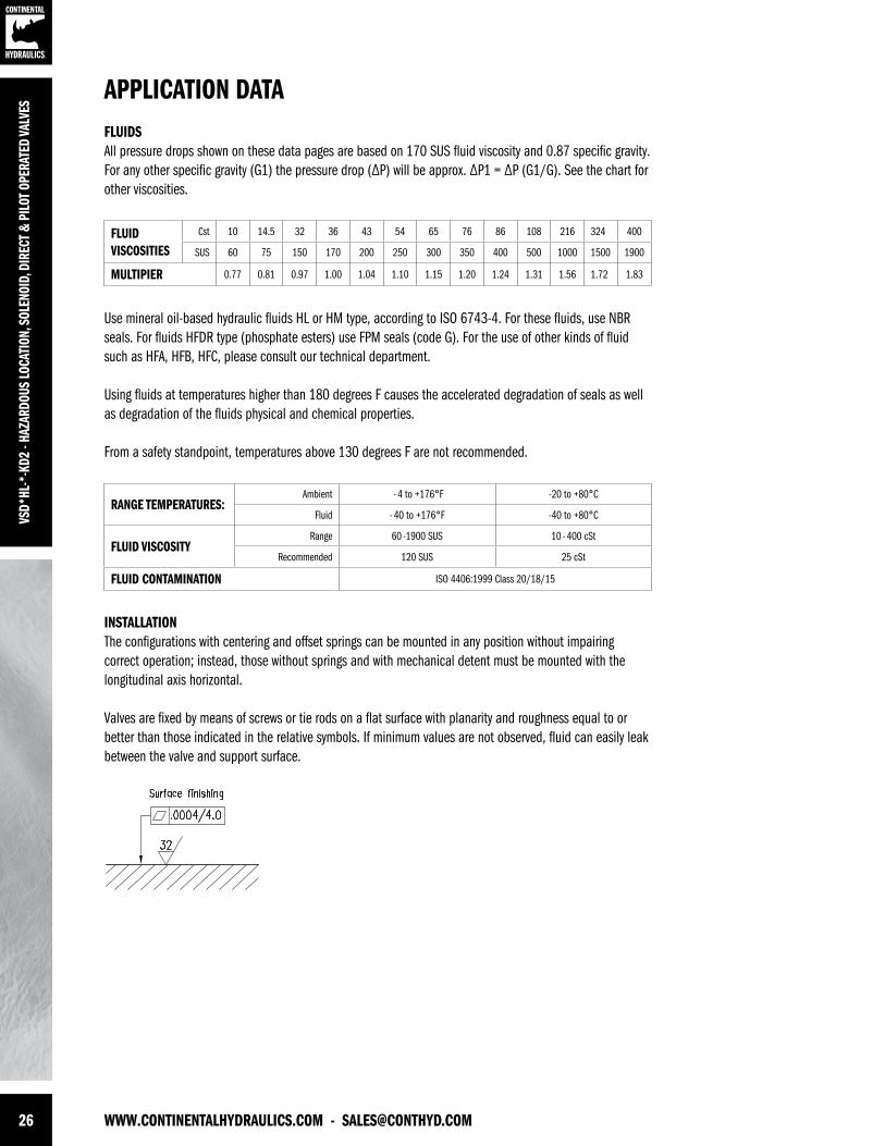
26 WWW.CONTINENTALHYDRAULICS.COM - [email protected]
VSD*
HL-*
-KD2
- HA
ZARD
OUS
LOCA
TION
, SOL
ENOI
D, D
IREC
T & P
ILOT
OPE
RATE
D VA
LVES
APPLICATION DATAFLUIDS All pressure drops shown on these data pages are based on 170 SUS fluid viscosity and 0.87 specific gravity. For any other specific gravity (G1) the pressure drop (∆P) will be approx. ∆P1 = ∆P (G1/G). See the chart for other viscosities.
Use mineral oil-based hydraulic fluids HL or HM type, according to ISO 6743-4. For these fluids, use NBR seals. For fluids HFDR type (phosphate esters) use FPM seals (code G). For the use of other kinds of fluid such as HFA, HFB, HFC, please consult our technical department.
Using fluids at temperatures higher than 180 degrees F causes the accelerated degradation of seals as well as degradation of the fluids physical and chemical properties.
From a safety standpoint, temperatures above 130 degrees F are not recommended.
INSTALLATIONThe configurations with centering and offset springs can be mounted in any position without impairing correct operation; instead, those without springs and with mechanical detent must be mounted with the longitudinal axis horizontal.
Valves are fixed by means of screws or tie rods on a flat surface with planarity and roughness equal to or better than those indicated in the relative symbols. If minimum values are not observed, fluid can easily leak between the valve and support surface.
FLUIDVISCOSITIES
Cst 10 14.5 32 36 43 54 65 76 86 108 216 324 400
SUS 60 75 150 170 200 250 300 350 400 500 1000 1500 1900
MULTIPIER 0.77 0.81 0.97 1.00 1.04 1.10 1.15 1.20 1.24 1.31 1.56 1.72 1.83
RANGE TEMPERATURES: Ambient - 4 to +176°F -20 to +80°C
Fluid - 40 to +176°F -40 to +80°C
FLUID VISCOSITYRange 60 -1900 SUS 10 - 400 cSt
Recommended 120 SUS 25 cSt
FLUID CONTAMINATION ISO 4406:1999 Class 20/18/15
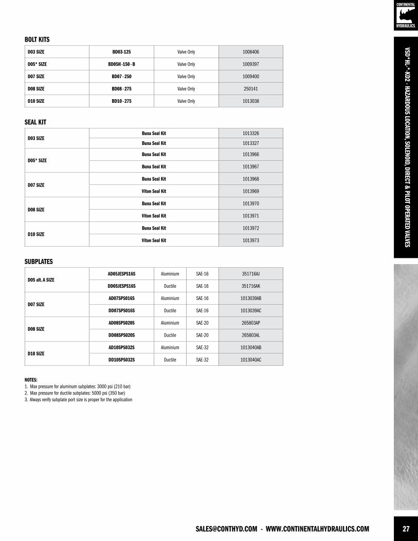
[email protected] - WWW.CONTINENTALHYDRAULICS.COM 27
VSD*HL-*-KD2 - HAZARDOUS LOCATION, SOLENOID, DIRECT & PILOT OPERATED VALVES
SEAL KIT
BOLT KITS
D03 SIZE BD03-125 Valve Only 1008406
D05* SIZE BD05H -150 - B Valve Only 1009397
D07 SIZE BD07 - 250 Valve Only 1009400
D08 SIZE BD08 - 275 Valve Only 250141
D10 SIZE BD10 - 275 Valve Only 1013038
D03 SIZEBuna Seal Kit 1013326
Buna Seal Kit 1013327
D05* SIZEBuna Seal Kit 1013966
Buna Seal Kit 1013967
D07 SIZEBuna Seal Kit 1013968
Viton Seal Kit 1013969
D08 SIZEBuna Seal Kit 1013970
Viton Seal Kit 1013971
D10 SIZEBuna Seal Kit 1013972
Viton Seal Kit 1013973
D05 alt. A SIZEAD05JESPS16S Aluminium SAE-16 351716AJ
DD05JESPS16S Ductile SAE-16 351716AK
D07 SIZEAD07SPS016S Aluminium SAE-16 1013039AB
DD07SPS016S Ductile SAE-16 1013039AC
D08 SIZEAD08SPS020S Aluminium SAE-20 265803AP
DD08SPS020S Ductile SAE-20 265803AL
D10 SIZEAD10SPS032S Aluminium SAE-32 1013040AB
DD10SPS032S Ductile SAE-32 1013040AC
NOTES:1. Max pressure for aluminum subplates: 3000 psi (210 bar) 2. Max pressure for ductile subplates: 5000 psi (350 bar)3. Always verify subplate port size is proper for the application
SUBPLATES
VSD*
HL-*
-KD2
- HA
ZARD
OUS
LOCA
TION
, SOL
ENOI
D, D
IREC
T & P
ILOT
OPE
RATE
D VA
LVES
FORM NO. 1017718. REV. 10/2013. © 2013 CONTINENTAL HYDRAULICS. ALL RIGHTS RESERVED. PRODUCT SPECIFICATIONS AND APPEARANCE ARE SUBJECT TO CHANGE WITHOUT NOTICE.
ABOUT CONTINENTAL HYDRAULICSRugged, durable, high-performance, efcient—the reason Continental Hydraulics’ products are used in some of the most challenging applications across the globe. With a commitment to quality customer
support and innovative engineering, Continental’s pumps, valves, power units, mobile and custom products deliver what the markets demand. Continental has been serving the food production, brick
and block, wood products, automotive and machine tool industries since 1962. Learn how our products survive some of the most harsh environments.
[email protected] WEST 123RD STREET • SAVAGE, MN 55378-1299 / PH: 952.895.6400 / FAX: 952.895.6444 / WWW.CONTINENTALHYDRAULICS.COM
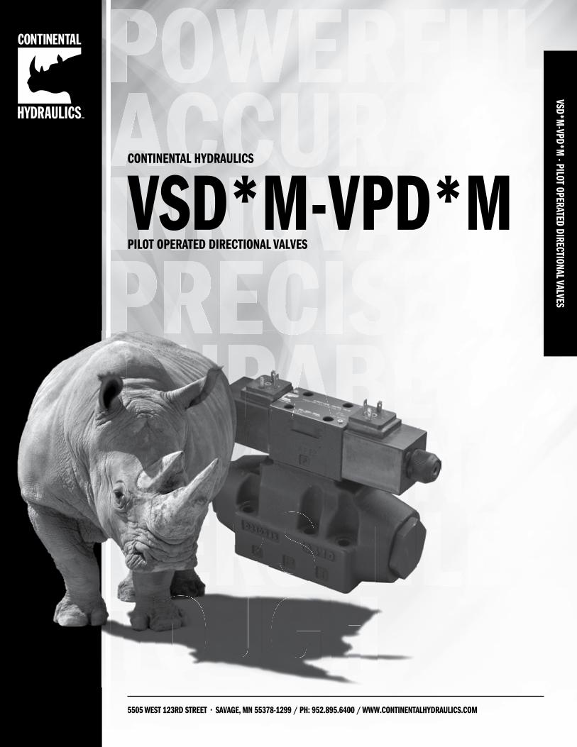
VSD*M-VPD*M
- PILOT OPERATED DIRECTIONAL VALVES
5505 WEST 123RD STREET • SAVAGE, MN 55378-1299 / PH: 952.895.6400 / WWW.CONTINENTALHYDRAULICS.COM
CONTINENTAL HYDRAULICS
PILOT OPERATED DIRECTIONAL VALVESVSD*M-VPD*M
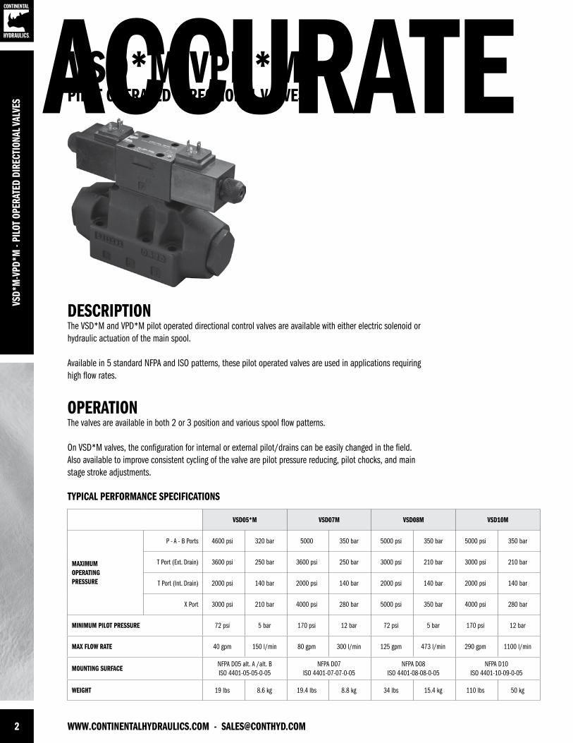
2 WWW.CONTINENTALHYDRAULICS.COM - [email protected]
ACCURATEVS
D*M
-VPD
*M -
PILO
T OP
ERAT
ED D
IREC
TION
AL V
ALVE
S
VSD*M-VPD*MPILOT OPERATED DIRECTIONAL VALVES
DESCRIPTIONThe VSD*M and VPD*M pilot operated directional control valves are available with either electric solenoid or hydraulic actuation of the main spool.
Available in 5 standard NFPA and ISO patterns, these pilot operated valves are used in applications requiring high flow rates.
OPERATIONThe valves are available in both 2 or 3 position and various spool flow patterns.
On VSD*M valves, the configuration for internal or external pilot/drains can be easily changed in the field. Also available to improve consistent cycling of the valve are pilot pressure reducing, pilot chocks, and main stage stroke adjustments.
TYPICAL PERFORMANCE SPECIFICATIONS
VSD05*M VSD07M VSD08M VSD10M
MAXIMUM OPERATINGPRESSURE
P - A - B Ports 4600 psi 320 bar 5000 350 bar 5000 psi 350 bar 5000 psi 350 bar
T Port (Ext. Drain) 3600 psi 250 bar 3600 psi 250 bar 3000 psi 210 bar 3000 psi 210 bar
T Port (Int. Drain) 2000 psi 140 bar 2000 psi 140 bar 2000 psi 140 bar 2000 psi 140 bar
X Port 3000 psi 210 bar 4000 psi 280 bar 5000 psi 350 bar 4000 psi 280 bar
MINIMUM PILOT PRESSURE 72 psi 5 bar 170 psi 12 bar 72 psi 5 bar 170 psi 12 bar
MAX FLOW RATE 40 gpm 150 l/min 80 gpm 300 l/min 125 gpm 473 l/min 290 gpm 1100 l/min
MOUNTING SURFACENFPA D05 alt. A /alt. BISO 4401-05-05-0-05
NFPA D07ISO 4401-07-07-0-05
NFPA D08ISO 4401-08-08-0-05
NFPA D10ISO 4401-10-09-0-05
WEIGHT 19 lbs 8.6 kg 19.4 lbs 8.8 kg 34 lbs 15.4 kg 110 lbs 50 kg
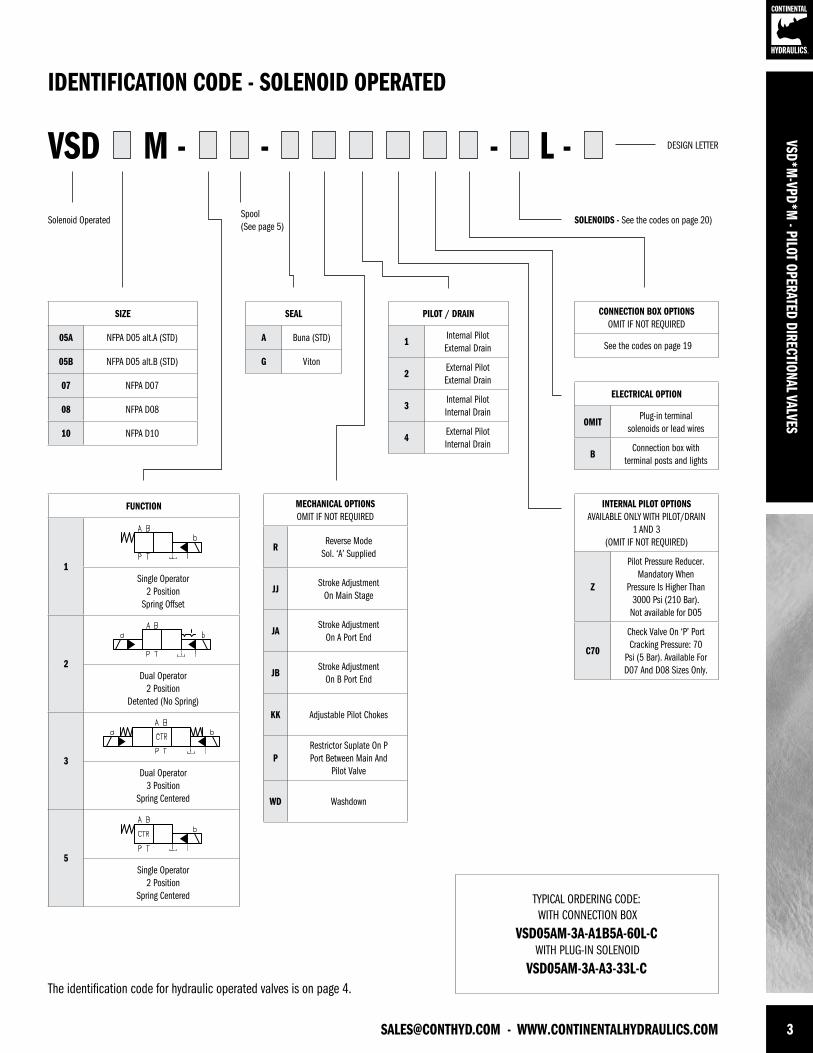
[email protected] - WWW.CONTINENTALHYDRAULICS.COM 3
SEAL
A Buna (STD)
G Viton
PILOT / DRAIN
1Internal Pilot External Drain
2External Pilot External Drain
3Internal Pilot Internal Drain
4External Pilot Internal Drain
SIZE
05A NFPA D05 alt.A (STD)
05B NFPA D05 alt.B (STD)
07 NFPA D07
08 NFPA D08
10 NFPA D10
MECHANICAL OPTIONSOMIT IF NOT REQUIRED
RReverse Mode
Sol. ‘A’ Supplied
JJStroke Adjustment
On Main Stage
JAStroke Adjustment
On A Port End
JBStroke Adjustment
On B Port End
KK Adjustable Pilot Chokes
PRestrictor Suplate On P Port Between Main And
Pilot Valve
WD Washdown
CONNECTION BOX OPTIONSOMIT IF NOT REQUIRED
See the codes on page 19
ELECTRICAL OPTION
OMITPlug-in terminal
solenoids or lead wires
BConnection box with
terminal posts and lights
INTERNAL PILOT OPTIONSAVAILABLE ONLY WITH PILOT/DRAIN
1 AND 3(OMIT IF NOT REQUIRED)
Z
Pilot Pressure Reducer.Mandatory When
Pressure Is Higher Than 3000 Psi (210 Bar).
Not available for D05
C70
Check Valve On ‘P’ PortCracking Pressure: 70
Psi (5 Bar). Available For D07 And D08 Sizes Only.
VSD M - L -- -
TYPICAL ORDERING CODE: WITH CONNECTION BOX
VSD05AM-3A-A1B5A-60L-C WITH PLUG-IN SOLENOID
VSD05AM-3A-A3-33L-C
IDENTIFICATION CODE - SOLENOID OPERATED
DESIGN LETTER
Spool(See page 5)
Solenoid Operated SOLENOIDS - See the codes on page 20)
VSD*M-VPD*M
- PILOT OPERATED DIRECTIONAL VALVES
FUNCTION
1Single Operator
2 PositionSpring Offset
2Dual Operator
2 PositionDetented (No Spring)
3Dual Operator
3 PositionSpring Centered
5Single Operator
2 PositionSpring Centered
The identification code for hydraulic operated valves is on page 4.
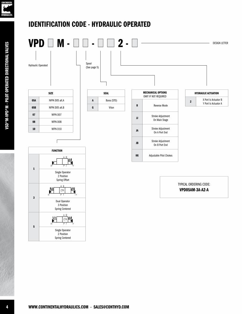
4 WWW.CONTINENTALHYDRAULICS.COM - [email protected]
VSD*
M-V
PD*M
- PI
LOT
OPER
ATED
DIR
ECTI
ONAL
VAL
VES
SEAL
A Buna (STD)
G Viton
HYDRAULIC ACTUATION
2X Port Is Actuator BY Port Is Actuator A
SIZE
05A NFPA D05 alt.A
05B NFPA D05 alt.B
07 NFPA D07
08 NFPA D08
10 NFPA D10
MECHANICAL OPTIONSOMIT IF NOT REQUIRED
R Reverse Mode
JJStroke Adjustment
On Main Stage
JAStroke Adjustment
On A Port End
JBStroke Adjustment
On B Port End
KK Adjustable Pilot Chokes
VPD M - 2 --
IDENTIFICATION CODE - HYDRAULIC OPERATED
DESIGN LETTER
Spool(See page 5)
Hydraulic Operated
FUNCTION
1Single Operator
2 PositionSpring Offset
3Dual Operator
3 PositionSpring Centered
5Single Operator
2 PositionSpring Centered
TYPICAL ORDERING CODE:
VPD05AM-3A-A2-A
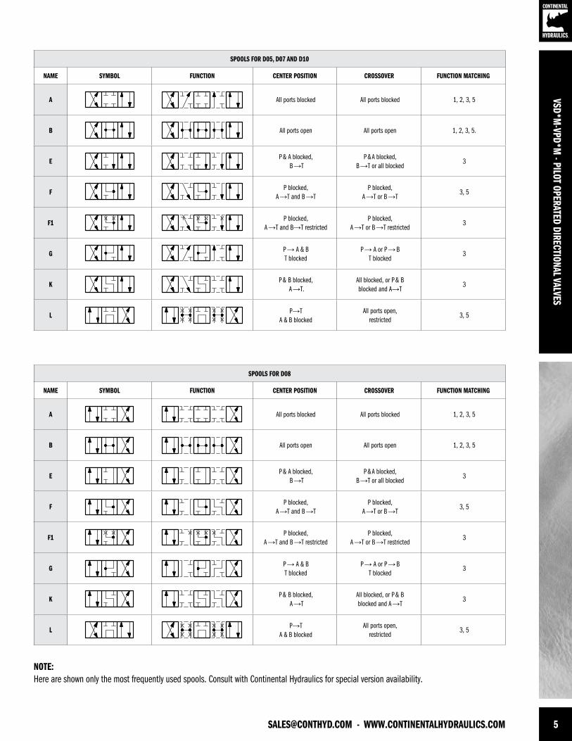
[email protected] - WWW.CONTINENTALHYDRAULICS.COM 5
VSD*M-VPD*M
- PILOT OPERATED DIRECTIONAL VALVES
SPOOLS FOR D05, D07 AND D10
NAME SYMBOL FUNCTION CENTER POSITION CROSSOVER FUNCTION MATCHING
A All ports blocked All ports blocked 1, 2, 3, 5
B All ports open All ports open 1, 2, 3, 5.
EP & A blocked,
B →TP & A blocked,
B →T or all blocked3
FP blocked,
A →T and B →TP blocked,
A →T or B →T3, 5
F1P blocked,
A →T and B→T restrictedP blocked,
A →T or B →T restricted3
GP → A & BT blocked
P → A or P → BT blocked
3
KP & B blocked,
A →T.All blocked, or P & Bblocked and A→T
3
LP→T
A & B blockedAll ports open,
restricted3, 5
SPOOLS FOR D08
NAME SYMBOL FUNCTION CENTER POSITION CROSSOVER FUNCTION MATCHING
A All ports blocked All ports blocked 1, 2, 3, 5
B All ports open All ports open 1, 2, 3, 5
EP & A blocked,
B →TP & A blocked,
B →T or all blocked3
FP blocked,
A →T and B →TP blocked,
A →T or B →T3, 5
F1P blocked,
A →T and B →T restrictedP blocked,
A →T or B →T restricted3
GP → A & BT blocked
P → A or P → BT blocked
3
KP & B blocked,
A →TAll blocked, or P & Bblocked and A →T
3
LP→T
A & B blockedAll ports open,
restricted3, 5
NOTE:Here are shown only the most frequently used spools. Consult with Continental Hydraulics for special version availability.
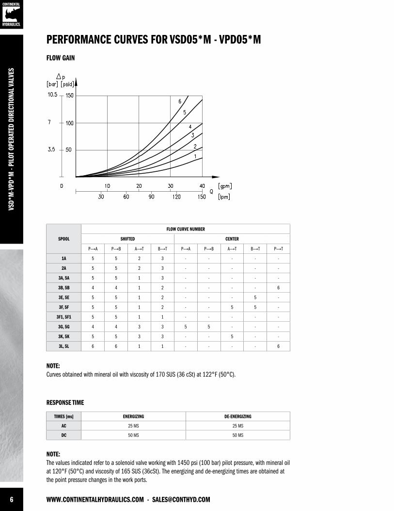
6 WWW.CONTINENTALHYDRAULICS.COM - [email protected]
VSD*
M-V
PD*M
- PI
LOT
OPER
ATED
DIR
ECTI
ONAL
VAL
VES
SPOOL
FLOW CURVE NUMBER
SHIFTED CENTER
P→A P→B A→T B→T P→A P→B A→T B→T P→T
1A 5 5 2 3 - - - - -
2A 5 5 2 3 - - - - -
3A, 5A 5 5 1 3 - - - - -
3B, 5B 4 4 1 2 - - - - 6
3E, 5E 5 5 1 2 - - - 5 -
3F, 5F 5 5 1 2 - - 5 5 -
3F1, 5F1 5 5 1 1 - - - - -
3G, 5G 4 4 3 3 5 5 - - -
3K, 5K 5 5 3 3 - - 5 - -
3L, 5L 6 6 1 1 - - - - 6
NOTE:Curves obtained with mineral oil with viscosity of 170 SUS (36 cSt) at 122°F (50°C).
NOTE:The values indicated refer to a solenoid valve working with 1450 psi (100 bar) pilot pressure, with mineral oil at 120°F (50°C) and viscosity of 165 SUS (36cSt). The energizing and de-energizing times are obtained at the point pressure changes in the work ports.
PERFORMANCE CURVES FOR VSD05*M - VPD05*MFLOW GAIN
RESPONSE TIME
TIMES [ms] ENERGIZING DE-ENERGIZING
AC 25 MS 25 MS
DC 50 MS 50 MS
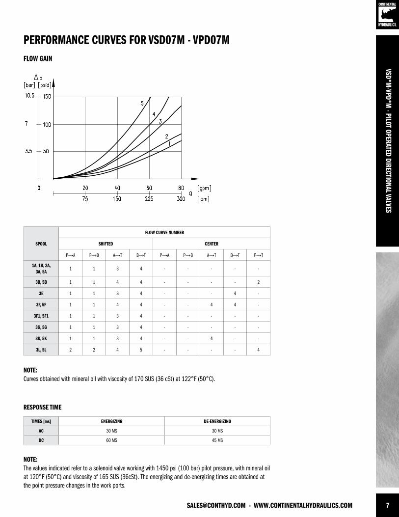
[email protected] - WWW.CONTINENTALHYDRAULICS.COM 7
VSD*M-VPD*M
- PILOT OPERATED DIRECTIONAL VALVES
SPOOL
FLOW CURVE NUMBER
SHIFTED CENTER
P→A P→B A→T B→T P→A P→B A→T B→T P→T
1A, 1B, 2A, 3A, 5A
1 1 3 4 - - - - -
3B, 5B 1 1 4 4 - - - - 2
3E 1 1 3 4 - - - 4 -
3F, 5F 1 1 4 4 - - 4 4 -
3F1, 5F1 1 1 3 4 - - - - -
3G, 5G 1 1 3 4 - - - - -
3K, 5K 1 1 3 4 - - 4 - -
3L, 5L 2 2 4 5 - - - - 4
NOTE:Curves obtained with mineral oil with viscosity of 170 SUS (36 cSt) at 122°F (50°C).
NOTE:The values indicated refer to a solenoid valve working with 1450 psi (100 bar) pilot pressure, with mineral oil at 120°F (50°C) and viscosity of 165 SUS (36cSt). The energizing and de-energizing times are obtained at the point pressure changes in the work ports.
PERFORMANCE CURVES FOR VSD07M - VPD07MFLOW GAIN
RESPONSE TIME
TIMES [ms] ENERGIZING DE-ENERGIZING
AC 30 MS 30 MS
DC 60 MS 45 MS
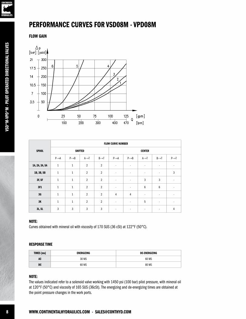
8 WWW.CONTINENTALHYDRAULICS.COM - [email protected]
SPOOL
FLOW CURVE NUMBER
SHIFTED CENTER
P→A P→B A→T B→T P→A P→B A→T B→T P→T
1A, 2A, 3A, 5A 1 1 2 2 - - - - -
1B, 3B, 5B 1 1 2 2 - - - - 3
3F, 5F 1 1 2 2 - - 3 3 -
3F1 1 1 2 2 - - 6 6 -
3G 1 1 2 2 4 4 - - -
3K 1 1 2 2 - - 5 - -
3L, 5L 3 3 3 3 - - - - 4
VSD*
M-V
PD*M
- PI
LOT
OPER
ATED
DIR
ECTI
ONAL
VAL
VES
NOTE:Curves obtained with mineral oil with viscosity of 170 SUS (36 cSt) at 122°F (50°C).
NOTE:The values indicated refer to a solenoid valve working with 1450 psi (100 bar) pilot pressure, with mineral oil at 120°F (50°C) and viscosity of 165 SUS (36cSt). The energizing and de-energizing times are obtained at the point pressure changes in the work ports.
PERFORMANCE CURVES FOR VSD08M - VPD08MFLOW GAIN
RESPONSE TIME
TIMES [ms] ENERGIZING DE-ENERGIZING
AC 30 MS 60 MS
DC 60 MS 80 MS
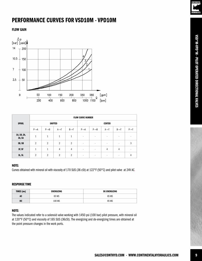
[email protected] - WWW.CONTINENTALHYDRAULICS.COM 9
SPOOL
FLOW CURVE NUMBER
SHIFTED CENTER
P→A P→B A→T B→T P→A P→B A→T B→T P→T
1A, 1B, 2A, 3A, 5A
1 1 1 1 - - - - -
3B, 5B 2 2 2 2 - - - - 3
3F, 5F 1 1 4 4 - - 4 4 -
3L, 5L 2 2 2 2 - - - - 4
VSD*M-VPD*M
- PILOT OPERATED DIRECTIONAL VALVES
NOTE:Curves obtained with mineral oil with viscosity of 170 SUS (36 cSt) at 122°F (50°C) and pilot valve at 24V AC.
NOTE:The values indicated refer to a solenoid valve working with 1450 psi (100 bar) pilot pressure, with mineral oil at 120°F (50°C) and viscosity of 165 SUS (36cSt). The energizing and de-energizing times are obtained at the point pressure changes in the work ports.
PERFORMANCE CURVES FOR VSD10M - VPD10MFLOW GAIN
RESPONSE TIME
TIMES [ms] ENERGIZING DE-ENERGIZING
AC 65 MS 65 MS
DC 100 MS 65 MS
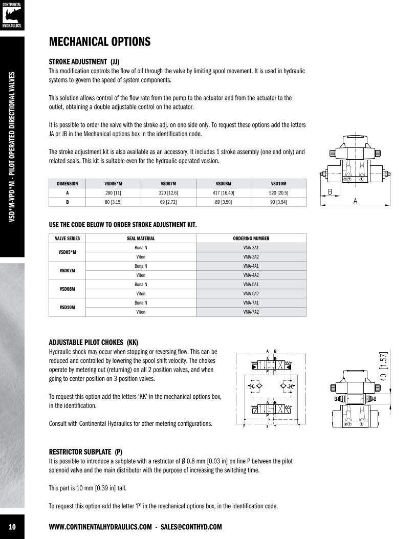
10 WWW.CONTINENTALHYDRAULICS.COM - [email protected]
VSD*
M-V
PD*M
- PI
LOT
OPER
ATED
DIR
ECTI
ONAL
VAL
VES
ADJUSTABLE PILOT CHOKES (KK)Hydraulic shock may occur when stopping or reversing flow. This can bereduced and controlled by lowering the spool shift velocity. The chokesoperate by metering out (returning) on all 2 position valves, and whengoing to center position on 3-position valves.
To request this option add the letters ‘KK’ in the mechanical options box,in the identification.
Consult with Continental Hydraulics for other metering configurations.
RESTRICTOR SUBPLATE (P)It is possible to introduce a subplate with a restrictor of Ø 0.8 mm [0.03 in] on line P between the pilot solenoid valve and the main distributor with the purpose of increasing the switching time.
This part is 10 mm [0.39 in] tall.
To request this option add the letter ‘P’ in the mechanical options box, in the identification code.
STROKE ADJUSTMENT (JJ)This modification controls the flow of oil through the valve by limiting spool movement. It is used in hydraulic systems to govern the speed of system components.
This solution allows control of the flow rate from the pump to the actuator and from the actuator to the outlet, obtaining a double adjustable control on the actuator.
It is possible to order the valve with the stroke adj. on one side only. To request these options add the letters JA or JB in the Mechanical options box in the identification code.
The stroke adjustment kit is also available as an accessory. It includes 1 stroke assembly (one end only) and related seals. This kit is suitable even for the hydraulic operated version.
MECHANICAL OPTIONS
DIMENSION VSD05*M VSD07M VSD08M VSD10M
A 280 [11] 320 [12.6] 417 [16.40] 520 [20.5]
B 80 [3.15] 69 [2.72] 89 [3.50] 90 [3.54]
VALVE SERIES SEAL MATERIAL ORDERING NUMBER
VSD05*MBuna N VMA-3A1
Viton VMA-3A2
VSD07MBuna N VMA-4A1
Viton VMA-4A2
VSD08MBuna N VMA-5A1
Viton VMA-5A2
VSD10MBuna N VMA-7A1
Viton VMA-7A2
USE THE CODE BELOW TO ORDER STROKE ADJUSTMENT KIT.
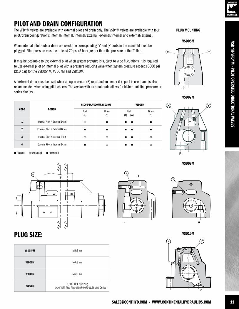
[email protected] - WWW.CONTINENTALHYDRAULICS.COM 11
VSD*M-VPD*M
- PILOT OPERATED DIRECTIONAL VALVES
PILOT AND DRAIN CONFIGURATIONThe VPD*M valves are available with external pilot and drain only. The VSD*M valves are available with four pilot/drain configurations: internal/internal, internal/external, external/internal and external/external.
When internal pilot and/or drain are used, the corresponding ‘x’ and ‘y’ ports in the manifold must be plugged. Pilot pressure must be at least 70 psi (5 bar) greater than the pressure in the ‘T’ line.
It may be desirable to use external pilot when system pressure is subject to wide flucuations. It is required to use external pilot or internal pilot with a pressure reducing valve when system pressure exceeds 3000 psi (210 bar) for the VSD05*M, VSD07M and VSD10M.
An external drain must be used when an open center (B) or a tandem center (L) spool is used, and is also recommended when using pilot checks. The version with external drain allows for higher tank line pressure in series circuits.
PLUG MOUNTING
VSD05M
VSD07M
PLUG SIZE:
CODE DESIGN
VSD05*M, VSD07M, VSD10M VSD08M
Pilot(X)
Drain(Y)
Pilot(X) (W)
Drain(Y)
1 Internal Pilot / External Drain
2 External Pilot / External Drain
3 Internal Pilot / Internal Drain
4 External Pilot / Internal Drain
VSD05*M M5x6 mm
VSD07M M6x8 mm
VSD10M M6x8 mm
VSD08M1/16” NPT Pipe Plug
1/16” NPT Pipe Plug with Ø 0.070 (1.78MM) Orifice
T
P
VSD08M
VSD10M
Plugged Unplugged Restricted
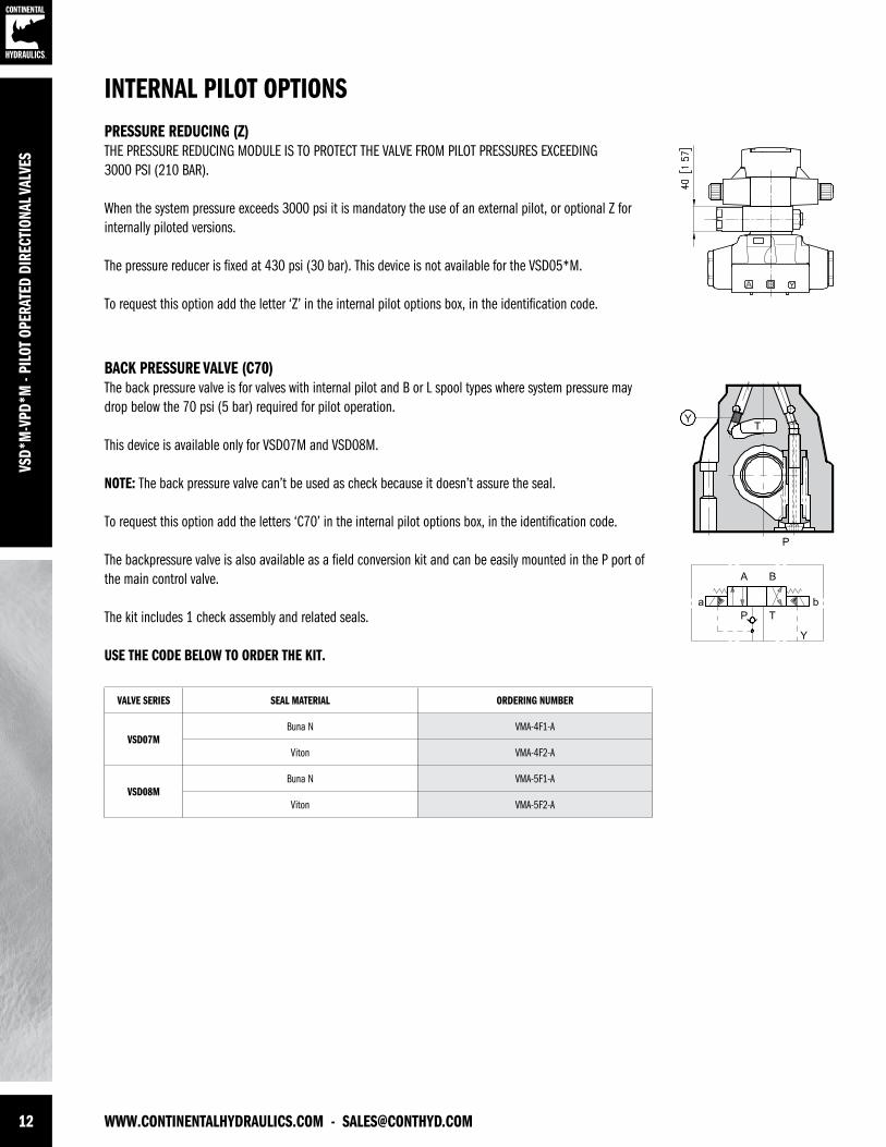
12 WWW.CONTINENTALHYDRAULICS.COM - [email protected]
VSD*
M-V
PD*M
- PI
LOT
OPER
ATED
DIR
ECTI
ONAL
VAL
VES
BACK PRESSURE VALVE (C70)The back pressure valve is for valves with internal pilot and B or L spool types where system pressure may drop below the 70 psi (5 bar) required for pilot operation.
This device is available only for VSD07M and VSD08M.
NOTE: The back pressure valve can’t be used as check because it doesn’t assure the seal.
To request this option add the letters ‘C70’ in the internal pilot options box, in the identification code.
The backpressure valve is also available as a field conversion kit and can be easily mounted in the P port of the main control valve.
The kit includes 1 check assembly and related seals.
USE THE CODE BELOW TO ORDER THE KIT.
PRESSURE REDUCING (Z)THE PRESSURE REDUCING MODULE IS TO PROTECT THE VALVE FROM PILOT PRESSURES EXCEEDING3000 PSI (210 BAR). When the system pressure exceeds 3000 psi it is mandatory the use of an external pilot, or optional Z for internally piloted versions.
The pressure reducer is fixed at 430 psi (30 bar). This device is not available for the VSD05*M.
To request this option add the letter ‘Z’ in the internal pilot options box, in the identification code.
INTERNAL PILOT OPTIONS
VALVE SERIES SEAL MATERIAL ORDERING NUMBER
VSD07MBuna N VMA-4F1-A
Viton VMA-4F2-A
VSD08MBuna N VMA-5F1-A
Viton VMA-5F2-A
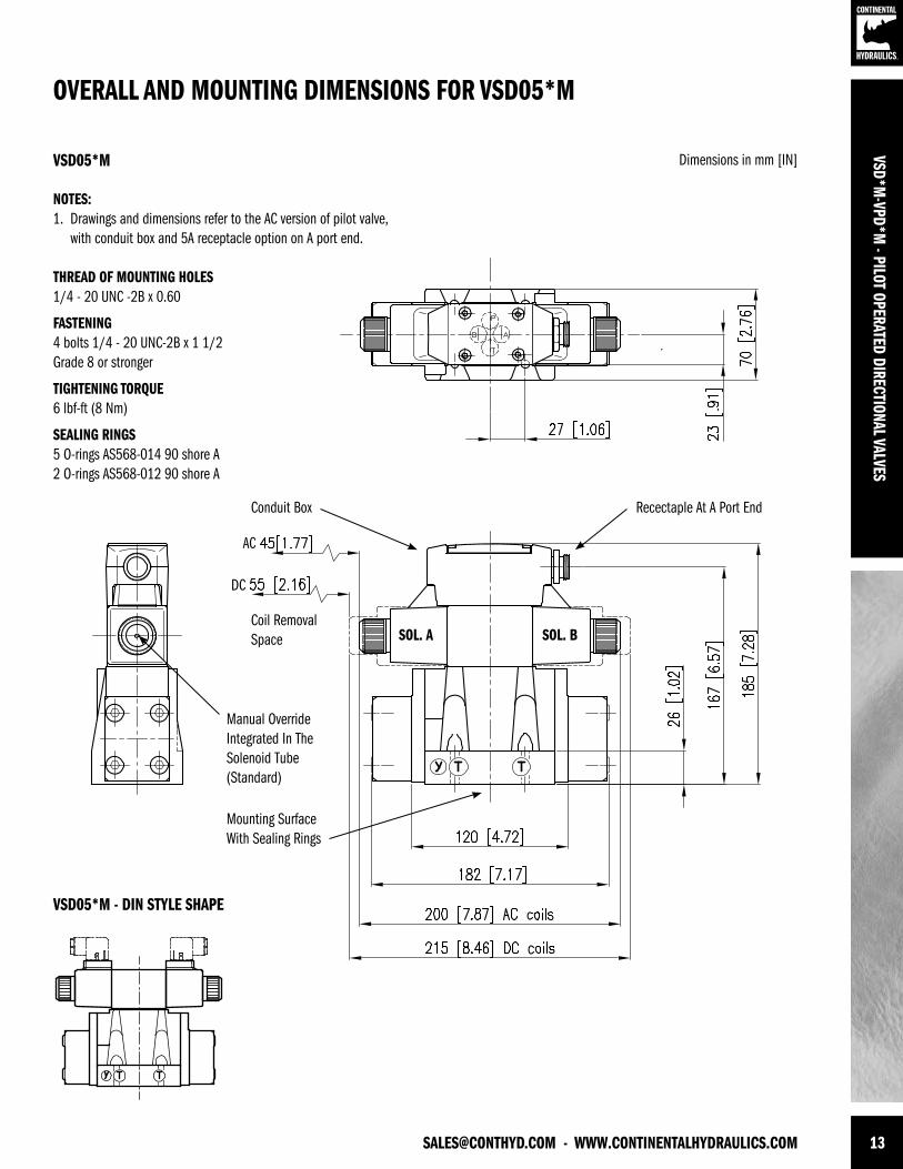
[email protected] - WWW.CONTINENTALHYDRAULICS.COM 13
VSD*M-VPD*M
- PILOT OPERATED DIRECTIONAL VALVES
Manual Override Integrated In TheSolenoid Tube (Standard)
Mounting Surface With Sealing Rings
Recectaple At A Port End
Coil Removal Space SOL. A SOL. B
NOTES:1. Drawings and dimensions refer to the AC version of pilot valve, with conduit box and 5A receptacle option on A port end.
THREAD OF MOUNTING HOLES1/4 - 20 UNC -2B x 0.60
FASTENING4 bolts 1/4 - 20 UNC-2B x 1 1/2 Grade 8 or stronger
TIGHTENING TORQUE6 lbf-ft (8 Nm)
SEALING RINGS5 O-rings AS568-014 90 shore A 2 O-rings AS568-012 90 shore A
OVERALL AND MOUNTING DIMENSIONS FOR VSD05*M
Dimensions in mm [IN]VSD05*M
VSD05*M - DIN STYLE SHAPE
Conduit Box
AC
DC
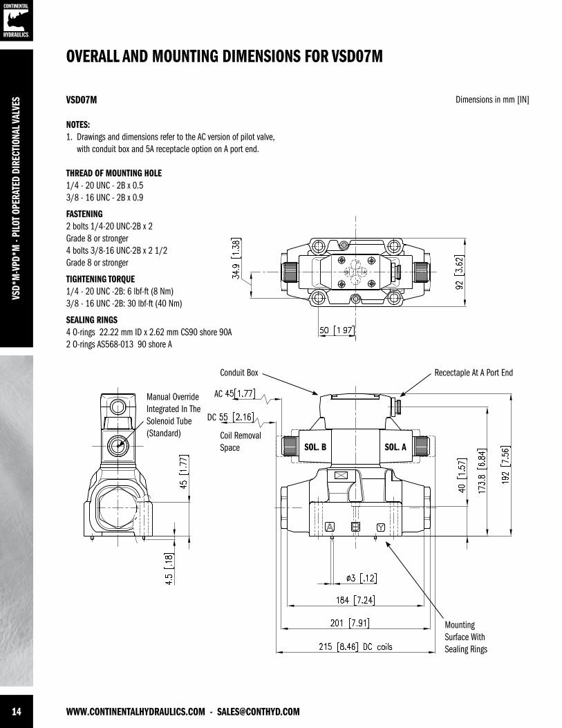
14 WWW.CONTINENTALHYDRAULICS.COM - [email protected]
VSD*
M-V
PD*M
- PI
LOT
OPER
ATED
DIR
ECTI
ONAL
VAL
VES
Manual Override Integrated In TheSolenoid Tube (Standard)
Mounting Surface With Sealing Rings
Coil Removal Space
NOTES:1. Drawings and dimensions refer to the AC version of pilot valve, with conduit box and 5A receptacle option on A port end.
THREAD OF MOUNTING HOLE 1/4 - 20 UNC - 2B x 0.5 3/8 - 16 UNC - 2B x 0.9
FASTENING2 bolts 1/4-20 UNC-2B x 2 Grade 8 or stronger4 bolts 3/8-16 UNC-2B x 2 1/2 Grade 8 or stronger
TIGHTENING TORQUE1/4 - 20 UNC -2B: 6 lbf-ft (8 Nm) 3/8 - 16 UNC -2B: 30 lbf-ft (40 Nm)
SEALING RINGS4 O-rings 22.22 mm ID x 2.62 mm CS90 shore 90A2 O-rings AS568-013 90 shore A
Conduit Box
AC
DC
Recectaple At A Port End
SOL. ASOL. B
OVERALL AND MOUNTING DIMENSIONS FOR VSD07M
Dimensions in mm [IN]VSD07M
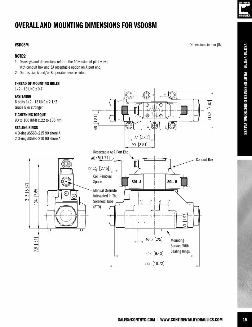
[email protected] - WWW.CONTINENTALHYDRAULICS.COM 15
VSD*M-VPD*M
- PILOT OPERATED DIRECTIONAL VALVES
Mounting Surface With Sealing Rings
Manual Override Integrated In TheSolenoid Tube (STD)
Coil RemovalSpace
NOTES:1. Drawings and dimensions refer to the AC version of pilot valve, with conduit box and 5A receptacle option on A port end.2. On this size A and/or B operator reverse sides.
THREAD OF MOUNTING HOLES 1/2 - 13 UNC x 0.7
FASTENING6 bolts 1/2 - 13 UNC x 2 1/2 Grade 8 or stronger
TIGHTENING TORQUE90 to 100 lbf-ft (122 to 136 Nm)
SEALING RINGS4 O-ring AS568 -215 90 shore A 2 O-ring AS568 -210 90 shore A
Conduit Box
Recectaple At A Port End AC
DC
SOL. A SOL. B
OVERALL AND MOUNTING DIMENSIONS FOR VSD08M
Dimensions in mm [IN]VSD08M
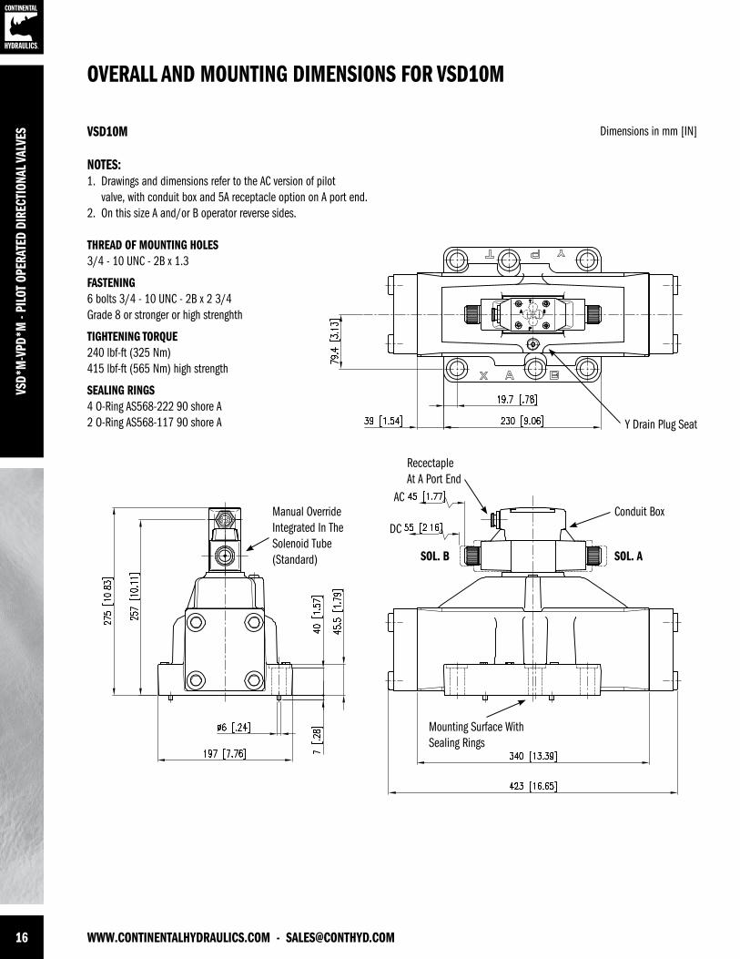
16 WWW.CONTINENTALHYDRAULICS.COM - [email protected]
VSD*
M-V
PD*M
- PI
LOT
OPER
ATED
DIR
ECTI
ONAL
VAL
VES
Mounting Surface With Sealing Rings
Manual Override Integrated In TheSolenoid Tube (Standard)
Y Drain Plug Seat
NOTES:1. Drawings and dimensions refer to the AC version of pilot valve, with conduit box and 5A receptacle option on A port end.2. On this size A and/or B operator reverse sides.
THREAD OF MOUNTING HOLES 3/4 - 10 UNC - 2B x 1.3
FASTENING6 bolts 3/4 - 10 UNC - 2B x 2 3/4 Grade 8 or stronger or high strenghth
TIGHTENING TORQUE240 lbf-ft (325 Nm) 415 lbf-ft (565 Nm) high strength
SEALING RINGS4 O-Ring AS568-222 90 shore A 2 O-Ring AS568-117 90 shore A
Conduit Box
Recectaple At A Port End
AC
DC
SOL. B SOL. A
OVERALL AND MOUNTING DIMENSIONS FOR VSD10M
Dimensions in mm [IN]VSD10M
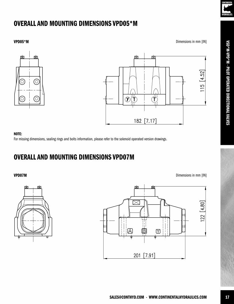
[email protected] - WWW.CONTINENTALHYDRAULICS.COM 17
VSD*M-VPD*M
- PILOT OPERATED DIRECTIONAL VALVES
NOTE:For missing dimensions, sealing rings and bolts information, please refer to the solenoid operated version drawings.
OVERALL AND MOUNTING DIMENSIONS VPD05*M
OVERALL AND MOUNTING DIMENSIONS VPD07M
Dimensions in mm [IN]
Dimensions in mm [IN]
VPD05*M
VPD07M
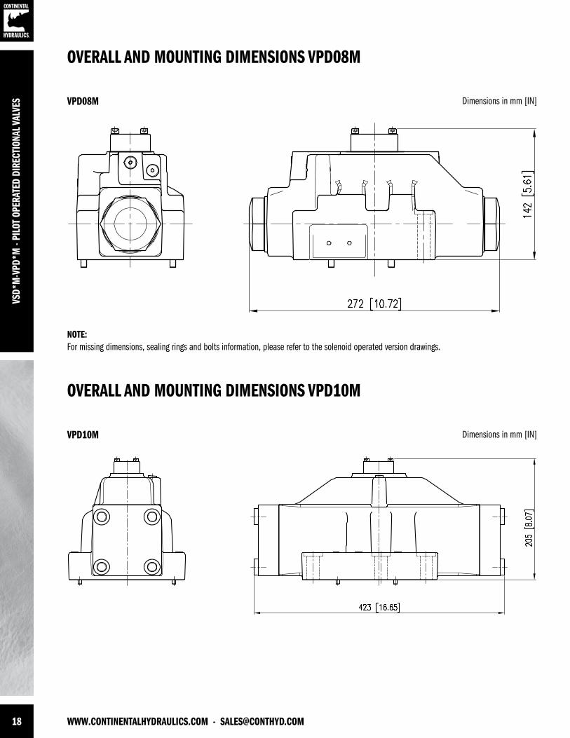
18 WWW.CONTINENTALHYDRAULICS.COM - [email protected]
VSD*
M-V
PD*M
- PI
LOT
OPER
ATED
DIR
ECTI
ONAL
VAL
VES
NOTE:For missing dimensions, sealing rings and bolts information, please refer to the solenoid operated version drawings.
OVERALL AND MOUNTING DIMENSIONS VPD08M
OVERALL AND MOUNTING DIMENSIONS VPD10M
Dimensions in mm [IN]
Dimensions in mm [IN]
VPD08M
VPD10M
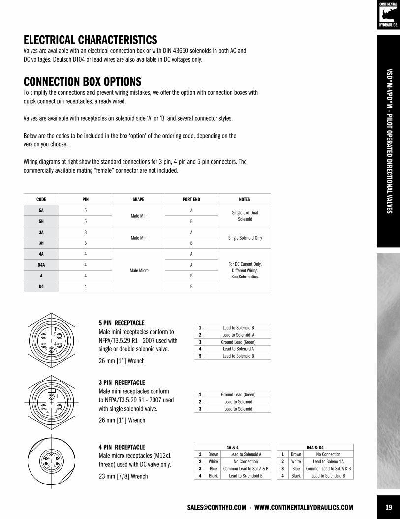
[email protected] - WWW.CONTINENTALHYDRAULICS.COM 19
VSD*M-VPD*M
- PILOT OPERATED DIRECTIONAL VALVES
ELECTRICAL CHARACTERISTICSValves are available with an electrical connection box or with DIN 43650 solenoids in both AC andDC voltages. Deutsch DT04 or lead wires are also available in DC voltages only.
CONNECTION BOX OPTIONSTo simplify the connections and prevent wiring mistakes, we offer the option with connection boxes with quick connect pin receptacles, already wired.
Valves are available with receptacles on solenoid side ‘A’ or ‘B’ and several connector styles.
Below are the codes to be included in the box ‘option’ of the ordering code, depending on theversion you choose.
Wiring diagrams at right show the standard connections for 3-pin, 4-pin and 5-pin connectors. Thecommercially available mating “female” connector are not included.
CODE PIN SHAPE PORT END NOTES
5A 5Male Mini
A Single and DualSolenoid5H 5 B
3A 3Male Mini
ASingle Solenoid Only
3H 3 B
4A 4
Male Micro
A
For DC Current Only. Different Wiring.See Schematics.
D4A 4 A
4 4 B
D4 4 B
5 PIN RECEPTACLEMale mini receptacles conform to NFPA/T3.5.29 R1 - 2007 used with single or double solenoid valve.
26 mm [1” ] Wrench
3 PIN RECEPTACLEMale mini receptacles conform to NFPA/T3.5.29 R1 - 2007 used with single solenoid valve.
26 mm [1” ] Wrench
4 PIN RECEPTACLEMale micro receptacles (M12x1 thread) used with DC valve only.
23 mm [7/8] Wrench
1 Lead to Solenoid B2 Lead to Solenoid A3 Ground Lead (Green)4 Lead to Solenoid A5 Lead to Solenoid B
1 Ground Lead (Green)2 Lead to Solenoid3 Lead to Solenoid
4A & 41 Brown Lead to Solenoid A2 White No Connection3 Blue Common Lead to Sol. A & B4 Black Lead to Solendoid B
D4A & D41 Brown No Connection2 White Lead to Solenoid A3 Blue Common Lead to Sol. A & B4 Black Lead to Solendoid B

20 WWW.CONTINENTALHYDRAULICS.COM - [email protected]
VSD*
M-V
PD*M
- PI
LOT
OPER
ATED
DIR
ECTI
ONAL
VAL
VES
DEUTSCH DT04 MALE
LEAD WIRES
SOLENOIDSListed below the types of solenoids available and the numbers to be added in the solenoid box on page 3.
PLUG-IN TERMINAL SOLENOID DIN 43650 This solenoid has three terminal posts. Use bi-polar connectors that meet ISO 4400 / DIN 43650(EN 175301-803). Protection against atmospheric agent: IP 65
LEAD WIRES6 inch length, protection against atmospheric agent: IP 67
DEUTSCH DT04 MALEProtection against atmospheric agent: IP 69Connectors must be ordered separately.
CONNECTION BOX SOLENOIDS This is a two pin solenoid which connects to the circuit board. Wiring is done on the terminal stripinside the box.
WASHDOWN OPTION (CODE WD)The wash-down option with the electrical box is designed for an IP65 rating. This option uses a special cover without the mounting bolt access holes and uses silicone sealant to help seal between the coil and core tube.
The DIN, Deutsch and lead wire coils versions of the wash-down option uses silicone sealant to help seal between the coil and core tube.
DIN CONNECTION
CODE
LEAD WIRE CONNECTION
CODE
DEUTSCH DT04
CONNECTION CODE
BOX CONNECTION
CODE
VOLTAGE & FREQ.
[VOLT - HERTZ]
VOLTAGE LIMITS
[MIN - MAX]
RESISTANCE±10%[OHM]
INRUSH CURRENT
[A]
HOLDING CURRENT
[A]
HOLDING POWER
[W]
33 Not Available Not Available 60120 - 60110 - 50
108 - 12699 - 116
35.71.351.41
0.460.53
2223
34 Not Available Not Available 61240 - 60 220 - 50
216 - 252198 - 231
146.40.610.71
0.230.26
2223
Not Available Not Available Not Available 68120 - 60110 - 50
108 - 13299 - 121
75.80.720.74
0.220.24
1010
42 24K4 24K7 70 24 V DC 21 - 26 19.2 1.25 1.25 30
44 12K4 12K7 75 12 V DC 10 - 13 4.8 2.5 2.5 30
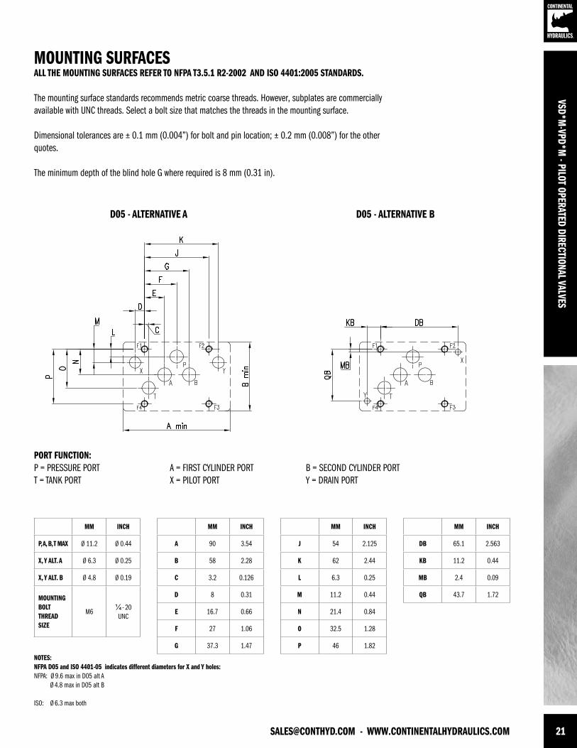
[email protected] - WWW.CONTINENTALHYDRAULICS.COM 21
VSD*M-VPD*M
- PILOT OPERATED DIRECTIONAL VALVES
PORT FUNCTION:P = PRESSURE PORT A = FIRST CYLINDER PORT B = SECOND CYLINDER PORTT = TANK PORT X = PILOT PORT Y = DRAIN PORT
NOTES:NFPA D05 and ISO 4401-05 indicates different diameters for X and Y holes:NFPA: Ø 9.6 max in D05 alt A Ø 4.8 max in D05 alt B
ISO: Ø 6.3 max both
MOUNTING SURFACESALL THE MOUNTING SURFACES REFER TO NFPA T3.5.1 R2-2002 AND ISO 4401:2005 STANDARDS.
The mounting surface standards recommends metric coarse threads. However, subplates are commercially available with UNC threads. Select a bolt size that matches the threads in the mounting surface.
Dimensional tolerances are ± 0.1 mm (0.004”) for bolt and pin location; ± 0.2 mm (0.008”) for the other quotes.
The minimum depth of the blind hole G where required is 8 mm (0.31 in).
MM INCH
P, A, B, T MAX Ø 11.2 Ø 0.44
X, Y ALT. A Ø 6.3 Ø 0.25
X, Y ALT. B Ø 4.8 Ø 0.19
MOUNTINGBOLT THREAD SIZE
M6¼ - 20 UNC
MM INCH
A 90 3.54
B 58 2.28
C 3.2 0.126
D 8 0.31
E 16.7 0.66
F 27 1.06
G 37.3 1.47
MM INCH
J 54 2.125
K 62 2.44
L 6.3 0.25
M 11.2 0.44
N 21.4 0.84
O 32.5 1.28
P 46 1.82
MM INCH
DB 65.1 2.563
KB 11.2 0.44
MB 2.4 0.09
QB 43.7 1.72
D05 - ALTERNATIVE A D05 - ALTERNATIVE B
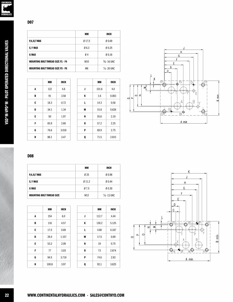
22 WWW.CONTINENTALHYDRAULICS.COM - [email protected]
VSD*
M-V
PD*M
- PI
LOT
OPER
ATED
DIR
ECTI
ONAL
VAL
VES
MM INCH
P, A, B, T MAX Ø 17.5 Ø 0.69
X, Y MAX Ø 6.3 Ø 0.25
G MAX Ø 4 Ø 0.16
MOUNTING BOLT THREAD SIZE F1 - F4 M10 ⅜ - 16 UNC
MOUNTING BOLT THREAD SIZE F5 - F6 M6 ¼ - 20 UNC
MM INCH
A 122 4.8
B 91 3.58
C 18.3 0.72
D 34.1 1.34
E 50 1.97
F 65.9 2.60
G 76.6 3.016
H 88.1 3.47
MM INCH
J 101.6 4.0
K 1.6 0.063
L 14.3 0.56
M 15.9 0.626
N 55.6 2.19
O 57.2 2.25
P 69.9 2.75
Q 71.5 2.815
MM INCH
P, A, B, T MAX Ø 25 Ø 0.98
X, Y MAX Ø 11.2 Ø 0.44
G MAX Ø 7.5 Ø 0.30
MOUNTING BOLT THREAD SIZE M12 ½ - 13 UNC
MM INCH
A 154 6.0
B 116 4.57
C 17.5 0.69
D 29.4 1.157
E 53.2 2.09
F 77 3.03
G 94.5 3.719
H 100.8 3.97
MM INCH
J 112.7 4.44
K 130.2 5.125
L 4.80 0.187
M 17.5 0.69
N 19 0.75
O 73 2.874
P 74.6 2.93
Q 92.1 3.625
D07
D08

[email protected] - WWW.CONTINENTALHYDRAULICS.COM 23
VSD*M-VPD*M
- PILOT OPERATED DIRECTIONAL VALVES
MM INCH
P, A, B, T MAX Ø 32 Ø 1.25
X, Y MAX Ø 11.2 Ø .44
G MAX Ø 7.5 Ø .30
MOUNTING BOLT THREAD SIZE M20 ¾ - 10 UNC
MM INCH
A 230 9.06
B 199 7.83
C 41.3 1.63
D 76.2 3.0
E 82.5 3.25
F 114.3 4.5
G 138.6 5.457
H 147.6 5.81
MM INCH
J 168.3 6.63
K 190.5 7.5
L 35 1.38
M 44.5 1.75
N 123.8 4.87
O 130.2 5.13
P 158.8 6.25
D10
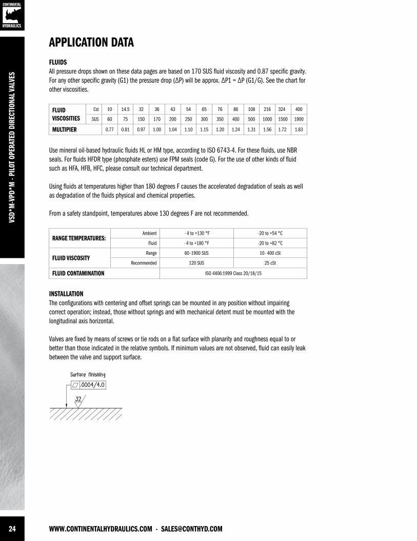
24 WWW.CONTINENTALHYDRAULICS.COM - [email protected]
VSD*
M-V
PD*M
- PI
LOT
OPER
ATED
DIR
ECTI
ONAL
VAL
VES
APPLICATION DATAFLUIDS All pressure drops shown on these data pages are based on 170 SUS fluid viscosity and 0.87 specific gravity. For any other specific gravity (G1) the pressure drop (∆P) will be approx. ∆P1 = ∆P (G1/G). See the chart for other viscosities.
Use mineral oil-based hydraulic fluids HL or HM type, according to ISO 6743-4. For these fluids, use NBR seals. For fluids HFDR type (phosphate esters) use FPM seals (code G). For the use of other kinds of fluid such as HFA, HFB, HFC, please consult our technical department.
Using fluids at temperatures higher than 180 degrees F causes the accelerated degradation of seals as well as degradation of the fluids physical and chemical properties.
From a safety standpoint, temperatures above 130 degrees F are not recommended.
INSTALLATIONThe configurations with centering and offset springs can be mounted in any position without impairing correct operation; instead, those without springs and with mechanical detent must be mounted with the longitudinal axis horizontal.
Valves are fixed by means of screws or tie rods on a flat surface with planarity and roughness equal to or better than those indicated in the relative symbols. If minimum values are not observed, fluid can easily leak between the valve and support surface.
FLUIDVISCOSITIES
Cst 10 14.5 32 36 43 54 65 76 86 108 216 324 400
SUS 60 75 150 170 200 250 300 350 400 500 1000 1500 1900
MULTIPIER 0.77 0.81 0.97 1.00 1.04 1.10 1.15 1.20 1.24 1.31 1.56 1.72 1.83
RANGE TEMPERATURES: Ambient - 4 to +130 °F -20 to +54 °C
Fluid - 4 to +180 °F -20 to +82 °C
FLUID VISCOSITYRange 60 -1900 SUS 10 - 400 cSt
Recommended 120 SUS 25 cSt
FLUID CONTAMINATION ISO 4406:1999 Class 20/18/15
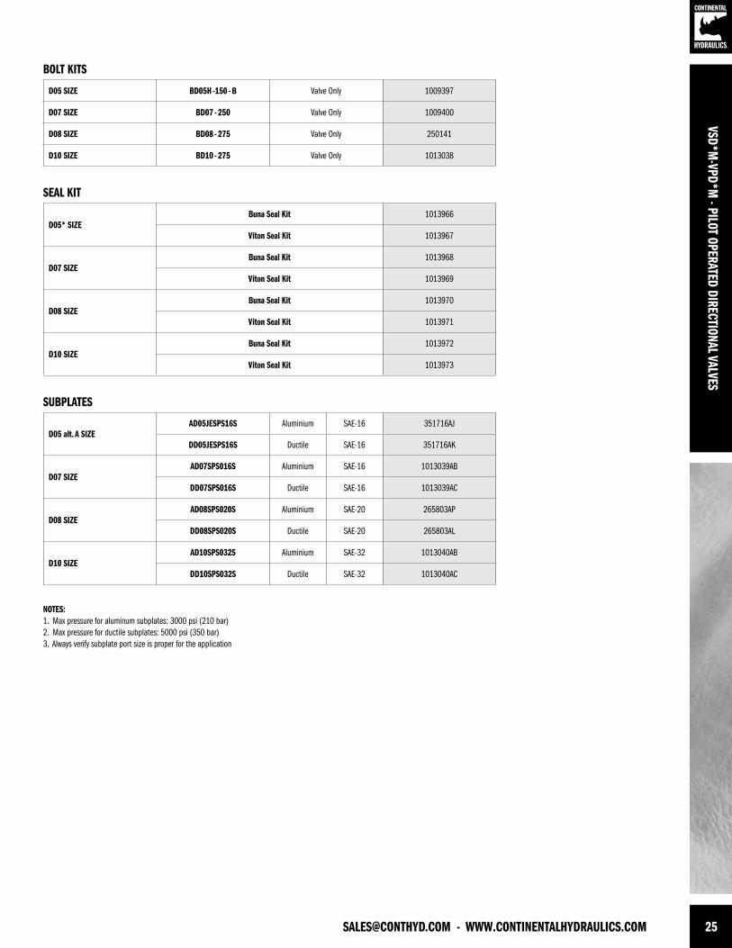
[email protected] - WWW.CONTINENTALHYDRAULICS.COM 25
VSD*M-VPD*M
- PILOT OPERATED DIRECTIONAL VALVES
SUBPLATES
SEAL KIT
BOLT KITS
D05 SIZE BD05H -150 - B Valve Only 1009397
D07 SIZE BD07 - 250 Valve Only 1009400
D08 SIZE BD08 - 275 Valve Only 250141
D10 SIZE BD10 - 275 Valve Only 1013038
D05* SIZEBuna Seal Kit 1013966
Viton Seal Kit 1013967
D07 SIZEBuna Seal Kit 1013968
Viton Seal Kit 1013969
D08 SIZEBuna Seal Kit 1013970
Viton Seal Kit 1013971
D10 SIZEBuna Seal Kit 1013972
Viton Seal Kit 1013973
D05 alt. A SIZEAD05JESPS16S Aluminium SAE-16 351716AJ
DD05JESPS16S Ductile SAE-16 351716AK
D07 SIZEAD07SPS016S Aluminium SAE-16 1013039AB
DD07SPS016S Ductile SAE-16 1013039AC
D08 SIZEAD08SPS020S Aluminium SAE-20 265803AP
DD08SPS020S Ductile SAE-20 265803AL
D10 SIZEAD10SPS032S Aluminium SAE-32 1013040AB
DD10SPS032S Ductile SAE-32 1013040AC
NOTES:1. Max pressure for aluminum subplates: 3000 psi (210 bar) 2. Max pressure for ductile subplates: 5000 psi (350 bar)3. Always verify subplate port size is proper for the application

VSD*
M-V
PD*M
- PI
LOT
OPER
ATED
DIR
ECTI
ONAL
VAL
VES
FORM NO. 1013800. REV. 04/20/2012. © 2012 CONTINENTAL HYDRAULICS. ALL RIGHTS RESERVED. PRODUCT SPECIFICATIONS AND APPEARANCE ARE SUBJECT TO CHANGE WITHOUT NOTICE.
ABOUT CONTINENTAL HYDRAULICSRugged, durable, high-performance, efcient—the reason Continental Hydraulics’ products are used in some of the most challenging applications across the globe. With a commitment to quality customer
support and innovative engineering, Continental’s pumps, valves, power units, mobile and custom products deliver what the markets demand. Continental has been serving the food production, brick
and block, wood products, automotive and machine tool industries since 1962. Learn how our products survive some of the most harsh environments.
[email protected] WEST 123RD STREET • SAVAGE, MN 55378-1299 / PH: 952.895.6400 / FAX: 952.895.6444 / WWW.CONTINENTALHYDRAULICS.COM
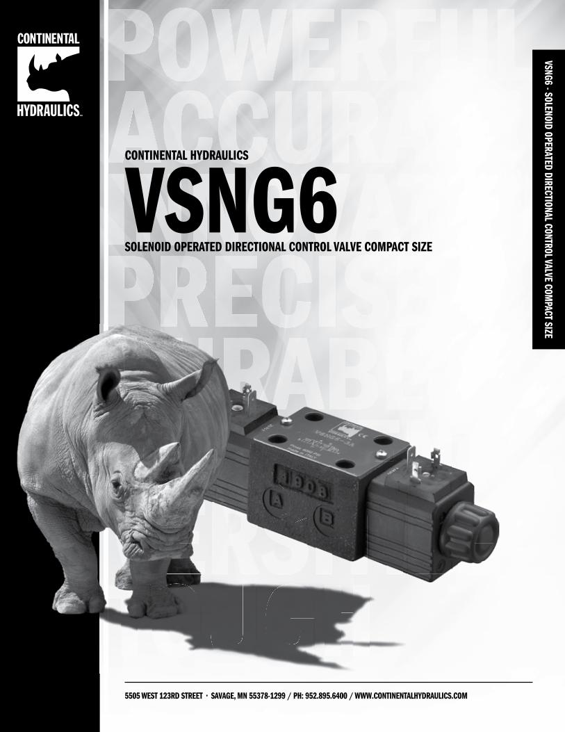
VSNG6 - SOLENOID OPERATED DIRECTIONAL CONTROL VALVE COMPACT SIZE
5505 WEST 123RD STREET • SAVAGE, MN 55378-1299 / PH: 952.895.6400 / WWW.CONTINENTALHYDRAULICS.COM
CONTINENTAL HYDRAULICS
VSNG6SOLENOID OPERATED DIRECTIONAL CONTROL VALVE COMPACT SIZE
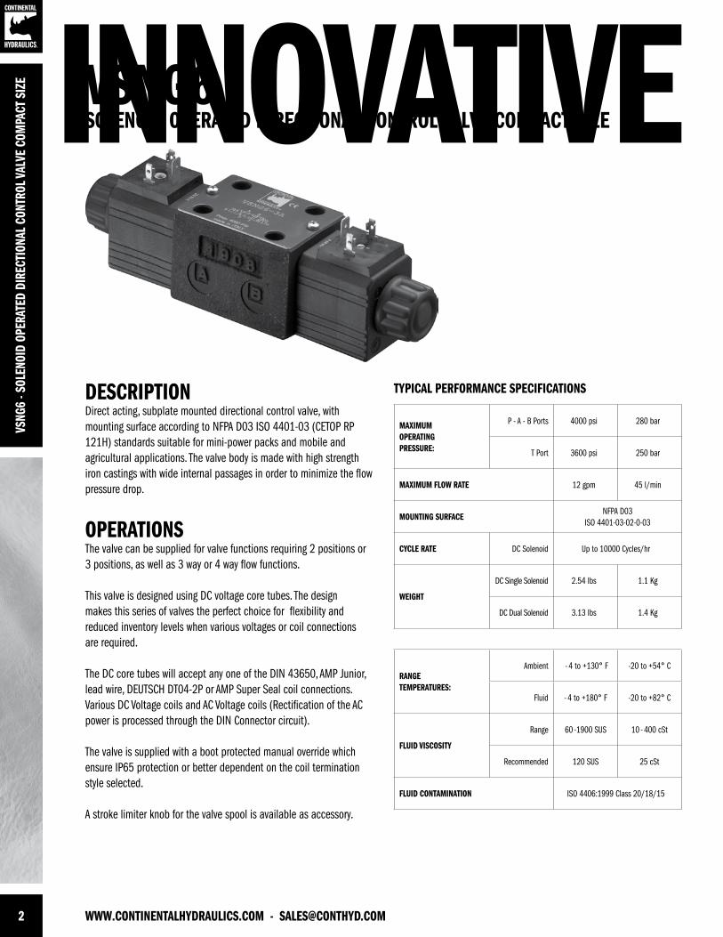
2 WWW.CONTINENTALHYDRAULICS.COM - [email protected]
INNOVATIVEVS
NG6
- SOL
ENOI
D OP
ERAT
ED D
IREC
TION
AL C
ONTR
OL V
ALVE
COM
PACT
SIZ
E VSNG6SOLENOID OPERATED DIRECTIONAL CONTROL VALVE COMPACT SIZE
DESCRIPTIONDirect acting, subplate mounted directional control valve, with mounting surface according to NFPA D03 ISO 4401-03 (CETOP RP 121H) standards suitable for mini-power packs and mobile and agricultural applications. The valve body is made with high strength iron castings with wide internal passages in order to minimize the flow pressure drop.
OPERATIONS The valve can be supplied for valve functions requiring 2 positions or 3 positions, as well as 3 way or 4 way flow functions.
This valve is designed using DC voltage core tubes. The design makes this series of valves the perfect choice for flexibility and reduced inventory levels when various voltages or coil connections are required.
The DC core tubes will accept any one of the DIN 43650, AMP Junior, lead wire, DEUTSCH DT04-2P or AMP Super Seal coil connections. Various DC Voltage coils and AC Voltage coils (Rectification of the AC power is processed through the DIN Connector circuit).
The valve is supplied with a boot protected manual override which ensure IP65 protection or better dependent on the coil termination style selected.
A stroke limiter knob for the valve spool is available as accessory.
TYPICAL PERFORMANCE SPECIFICATIONS
MAXIMUM OPERATINGPRESSURE:
P - A - B Ports 4000 psi 280 bar
T Port 3600 psi 250 bar
MAXIMUM FLOW RATE 12 gpm 45 l/min
MOUNTING SURFACENFPA D03
ISO 4401-03-02-0-03
CYCLE RATE DC Solenoid Up to 10000 Cycles/hr
WEIGHT
DC Single Solenoid 2.54 lbs 1.1 Kg
DC Dual Solenoid 3.13 lbs 1.4 Kg
RANGE TEMPERATURES:
Ambient - 4 to +130° F -20 to +54° C
Fluid - 4 to +180° F -20 to +82° C
FLUID VISCOSITY
Range 60 -1900 SUS 10 - 400 cSt
Recommended 120 SUS 25 cSt
FLUID CONTAMINATION ISO 4406:1999 Class 20/18/15
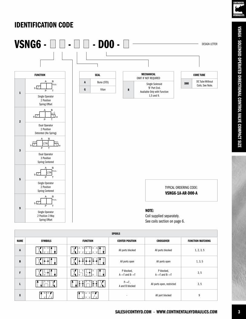
[email protected] - WWW.CONTINENTALHYDRAULICS.COM 3
SPOOLS
NAME SYMBOLS FUNCTION CENTER POSITION CROSSOVER FUNCTION MATCHING
A All ports blocked All ports blocked 1, 2, 3, 5
B All ports open All ports open 1, 3, 5
FP blocked,
A→T and B→TP blocked,
A→T and B→T3, 5
LP→T ,
A and B blockedAll ports open, restricted 3, 5
X - All port blocked 9
FUNCTION
1Single Operator
2 PositionSpring Offset
2Dual Operator
2 PositionDetented (No Spring)
3Dual Operator
3 PositionSpring Centered
5Single Operator
2 PositionSpring Centered
9Single Operator 2 Position 3 Way
Spring Offset
SEAL
A Buna (STD)
G Viton
CORE TUBE
D00DC Tube Without Coils. See Note.
MECHANICALOMIT IF NOT REQUIRED
R
Single Solenoid ‘B’ Port End.
Available Only with Function 1,5 and 9.
VSNG6 - - - D00 -
TYPICAL ORDERING CODE:
VSNG6-1A-AR-D00-A
IDENTIFICATION CODE
DESIGN LETTER
VSNG6 - SOLENOID OPERATED DIRECTIONAL CONTROL VALVE COMPACT SIZE
NOTE:Coil supplied separately.See coils section on page 6.
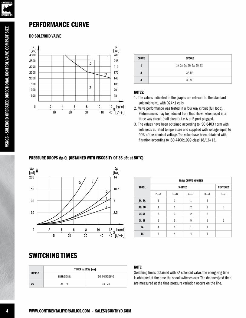
4 WWW.CONTINENTALHYDRAULICS.COM - [email protected]
VSNG
6 - S
OLEN
OID
OPER
ATED
DIR
ECTI
ONAL
CON
TROL
VAL
VE C
OMPA
CT S
IZE
NOTES:1. The values indicated in the graphs are relevant to the standard solenoid valve, with D24K1 coils. 2. Valve performance was tested in a four way circuit (full loop). Performances may be reduced from that shown when used in a three-way circuit (half circuit), i.e. A or B port plugged.3. The values have been obtained according to ISO 6403 norm with solenoids at rated temperature and supplied with voltage equal to 90% of the nominal voltage. The value have been obtained with filtration according to ISO 4406:1999 class 18/16/13.
NOTE:Switching times obtained with 3A solenoid valve. The energizing time is obtained at the time the spool switches over. The de-energized time are measured at the time pressure variation occurs on the line.
CURVE SPOOLS
1 1A, 2A, 3A, 3B, 5A, 5B, 9X
2 3F, 5F
3 3L, 5L
SPOOL
FLOW CURVE NUMBER
SHIFTED CENTERED
P→A P→B A→T B→T P→T
3A, 5A 1 1 1 1
3B, 5B 1 1 2 2 3
3F, 5F 3 3 2 2
3L, 5L 5 5 5 5 5
2A 1 1 1 1
1A 4 4 4 4
PERFORMANCE CURVE
SWITCHING TIMES
DC SOLENOID VALVE
PRESSURE DROPS ∆p-Q (OBTAINED WITH VISCOSITY OF 36 cSt at 50°C)
SUPPLYTIMES (±10%) [ms]
ENERGIZING DE-ENERGIZING
DC 25 - 75 15 - 25
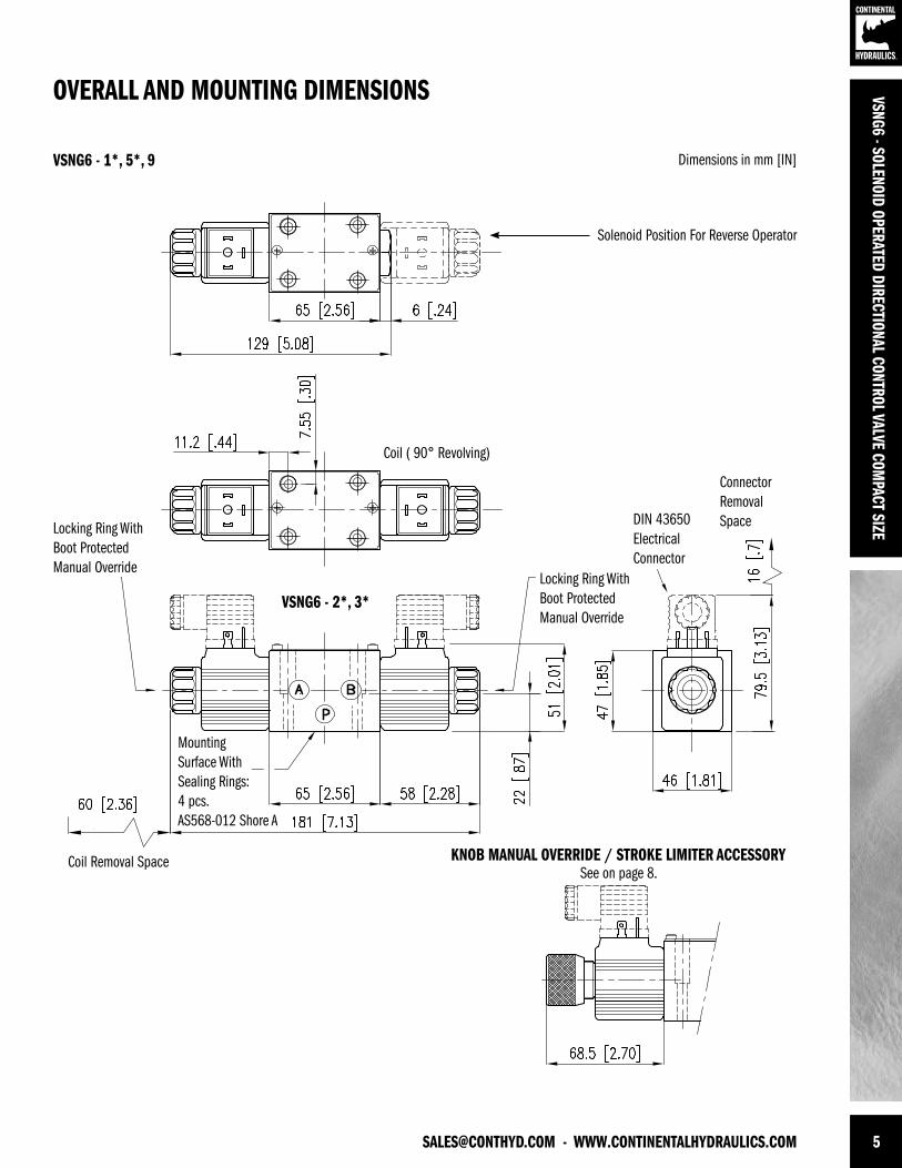
[email protected] - WWW.CONTINENTALHYDRAULICS.COM 5
VSNG6 - SOLENOID OPERATED DIRECTIONAL CONTROL VALVE COMPACT SIZE
KNOB MANUAL OVERRIDE / STROKE LIMITER ACCESSORYSee on page 8.
Solenoid Position For Reverse Operator
Mounting Surface With Sealing Rings:4 pcs.AS568-012 Shore A
Coil Removal Space
ConnectorRemovalSpace
Coil ( 90° Revolving)
Locking Ring With Boot ProtectedManual Override
DIN 43650ElectricalConnector
OVERALL AND MOUNTING DIMENSIONS
Dimensions in mm [IN]VSNG6 - 1*, 5*, 9
VSNG6 - 2*, 3*Locking Ring With Boot ProtectedManual Override
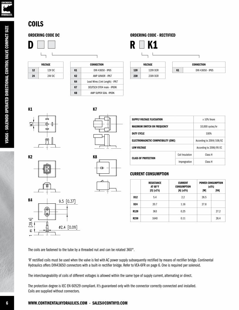
6 WWW.CONTINENTALHYDRAULICS.COM - [email protected]
VSNG
6 - S
OLEN
OID
OPER
ATED
DIR
ECTI
ONAL
CON
TROL
VAL
VE C
OMPA
CT S
IZE
The coils are fastened to the tube by a threaded nut and can be rotated 360°.
‘R’ rectified coils must be used when the valve is fed with AC power supply subsequently rectified by means of rectifier bridge. ContinentalHydraulics offers DIN43650 connectors with a built-in rectifier bridge. Refer to VEA-6FR on page 6. One is required per solenoid.
The interchangeability of coils of different voltages is allowed within the same type of supply current, alternating or direct.
The protection degree is IEC EN 60529 compliant. It’s guaranteed only with the connector correctly connected and installed. Coils are supplied without connectors.
ORDERING CODE DC
CURRENT CONSUMPTION
K1
K2
K4
K7
K8
ORDERING CODE - RECTIFIED
COILS
VOLTAGE
12 12V DC
24 24V DC
VOLTAGE
120 120V DCR
230 230V DCR
CONNECTION
K1 DIN 43650 - IP65
K2 AMP JUNIOR - IP67
K4 Lead Wires (1mt Length) - IP67
K7 DEUTSCH DT04 male - IP69K
K8 AMP SUPER SEAL IP69K
CONNECTION
K1 DIN 43650 - IP65
D R
SUPPLY VOLTAGE FLUCUATION ± 10% Vnom
MAXIMUM SWITCH ON FREQUENCY 10,000 cycles/hr
DUTY CYCLE 100%
ELECTROMAGNETIC COMPATIBILITY (EMC) According to 2004/108/EC
LOW VOLTAGE According to 2006/95 EC
CLASS OF PROTECTIONCoil Insulation Class H
Impregnation Class H
RESISTANCE AT 68°F
[Ω] (±1%)
CURRENT CONSUMPTION
[A] (±5%)
POWER CONSUMPTION(±5%)
[W] [VA]
D12 5.4 2.2 26.5
D24 20.7 1.16 27.8
R120 363 0.25 27.2
R230 1640 0.11 26.4
K1
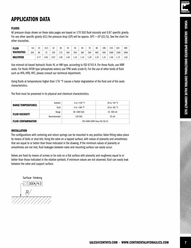
[email protected] - WWW.CONTINENTALHYDRAULICS.COM 7
VSNG6 - SOLENOID OPERATED DIRECTIONAL CONTROL VALVE COMPACT SIZE
APPLICATION DATAFLUIDSAll pressure drops shown on these data pages are based on 170 SUS fluid viscosity and 0.87 specific gravity. For any other specific gravity (G1) the pressure drop (∆P) will be approx. ∆P1 = ∆P (G1/G). See the chart for other viscosities.
Use mineral oil-based hydraulic fluids HL or HM type, according to ISO 6743-4. For these fluids, use NBR seals. For fluids HFDR type (phosphate esters) use FPM seals (code V). For the use of other kinds of fluid such as HFA, HFB, HFC, please consult our technical department.
Using fluids at temperatures higher than 176 °F causes a faster degradation of the fluid and of the seals characteristics.
The fluid must be preserved in its physical and chemical characteristics.
FLUIDVISCOSITIES
Cst 10 14.5 32 36 43 54 65 76 86 108 216 324 400
SUS 60 75 150 170 200 250 300 350 400 500 1000 1500 1900
MULTIPIER 0.77 0.81 0.97 1.00 1.04 1.10 1.15 1.20 1.24 1.31 1.56 1.72 1.83
INSTALLATIONThe configurations with centering and return springs can be mounted in any position. Valve fitting takes place by means of bolts or stud kits, fixing the valve on a lapped surface, with values of planarity and smoothness that are equal to or better than those indicated in the drawing. If the minimum values of planarity orsmoothness are not met, fluid leakages between valve and mounting surface can easily occur.
Valves are fixed by means of screws or tie rods on a flat surface with planarity and roughness equal to or better than those indicated in the relative symbols. If minimum values are not observed, fluid can easily leak between the valve and support surface.
RANGE TEMPERATURES: Ambient - 4 to +130 °F -20 to +54 °C
Fluid - 4 to +180 °F -20 to +82 °C
FLUID VISCOSITYRange 60 -1900 SUS 10 - 400 cSt
Recommended 120 SUS 25 cSt
FLUID CONTAMINATION ISO 4406:1999 Class 20/18/15
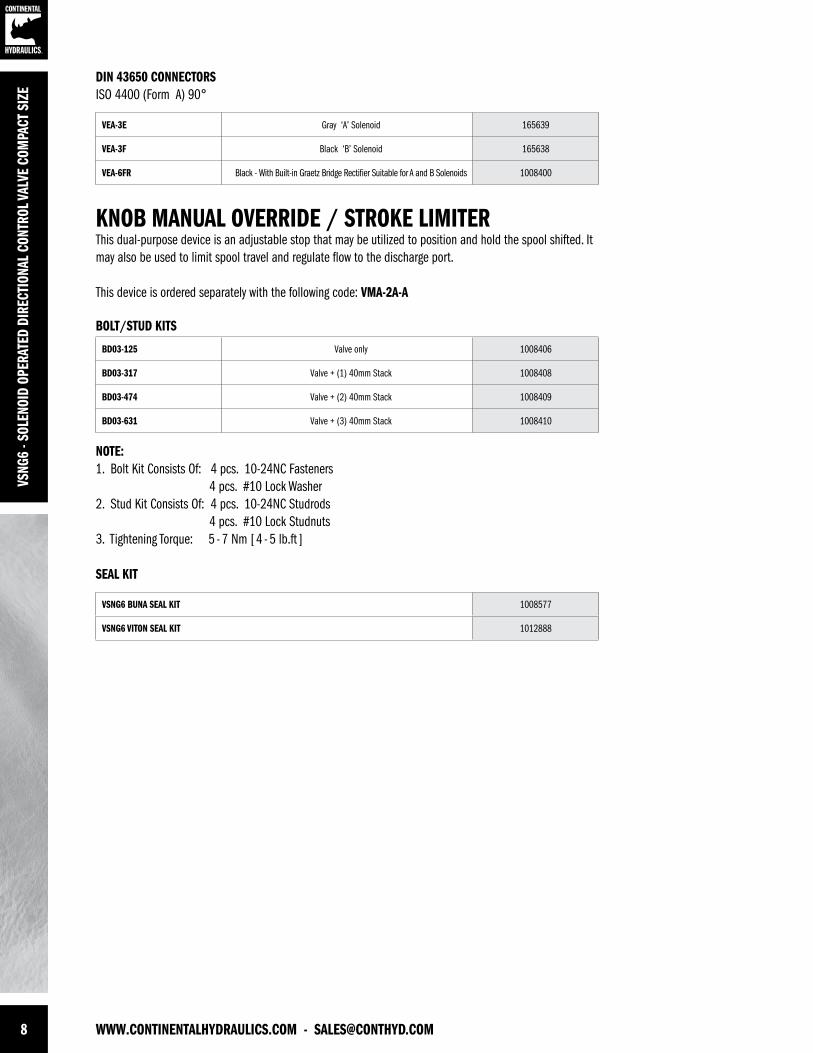
8 WWW.CONTINENTALHYDRAULICS.COM - [email protected]
VSNG
6 - S
OLEN
OID
OPER
ATED
DIR
ECTI
ONAL
CON
TROL
VAL
VE C
OMPA
CT S
IZE
KNOB MANUAL OVERRIDE / STROKE LIMITERThis dual-purpose device is an adjustable stop that may be utilized to position and hold the spool shifted. It may also be used to limit spool travel and regulate flow to the discharge port.
This device is ordered separately with the following code: VMA-2A-A
NOTE:1. Bolt Kit Consists Of: 4 pcs. 10-24NC Fasteners 4 pcs. #10 Lock Washer2. Stud Kit Consists Of: 4 pcs. 10-24NC Studrods 4 pcs. #10 Lock Studnuts3. Tightening Torque: 5 - 7 Nm [ 4 - 5 lb.ft ]
BOLT/STUD KITS
DIN 43650 CONNECTORSISO 4400 (Form A) 90°
SEAL KIT
BD03-125 Valve only 1008406
BD03-317 Valve + (1) 40mm Stack 1008408
BD03-474 Valve + (2) 40mm Stack 1008409
BD03-631 Valve + (3) 40mm Stack 1008410
VEA-3E Gray ‘A’ Solenoid 165639
VEA-3F Black ‘B’ Solenoid 165638
VEA-6FR Black - With Built-in Graetz Bridge Rectifier Suitable for A and B Solenoids 1008400
VSNG6 BUNA SEAL KIT 1008577
VSNG6 VITON SEAL KIT 1012888
[email protected] - WWW.CONTINENTALHYDRAULICS.COM 9
VSNG6 - SOLENOID OPERATED DIRECTIONAL CONTROL VALVE COMPACT SIZE
VSNG
6 - S
OLEN
OID
OPER
ATED
DIR
ECTI
ONAL
CON
TROL
VAL
VE C
OMPA
CT S
IZE
FORM NO. 1008705. REV. 7/2012. © 2011 CONTINENTAL HYDRAULICS. ALL RIGHTS RESERVED. PRODUCT SPECIFICATIONS AND APPEARANCE ARE SUBJECT TO CHANGE WITHOUT NOTICE.
ABOUT CONTINENTAL HYDRAULICSRugged, durable, high-performance, efcient—the reason Continental Hydraulics’ products are used in some of the most challenging applications across the globe. With a commitment to quality customer
support and innovative engineering, Continental’s pumps, valves, power units, mobile and custom products deliver what the markets demand. Continental has been serving the food production, brick
and block, wood products, automotive and machine tool industries since 1962. Learn how our products survive some of the most harsh environments.
[email protected] WEST 123RD STREET • SAVAGE, MN 55378-1299 / PH: 952.895.6400 / FAX: 952.895.6444 / WWW.CONTINENTALHYDRAULICS.COM