Embed Size (px)
Citation preview
48th International Conference on Environmental Systems ICES-2018-227 8-12 July 2018, Albuquerque, New Mexico
Copyright © 2018 MPB Communications Inc.
VMMO Lunar Volatile and Mineralogy Mapping Orbiter
Roman V. Kruzelecky1, Piotr Murzionak, Jonathan Lavoie,
Ian Sinclair and Gregory Schinn
MPB Communications Inc., 151 Hymus Blvd., Pointe Claire, Québec, H9R 1E9
Craig Underwood2, Yang Gao
3, Chris Bridges, Roberto Armellin, Andrea Luccafabris
Surrey Space Centre, University of Surrey, Guildford, UK
Edward Cloutis4
University of Winnipeg, 515 Portage Ave. Winnipeg, Manitoba, R3B 2E9
Johan Leijtens5
Lens Research & Development, s'Gravendijkseweg 41B, 2201CZ Noordwijk
Understanding the lunar near-surface distribution of relevant in-situ useable resources,
such as ilmenite (FeTiO3), and volatiles, such as water/ice, is vital to future sustained lunar
manned bases and commercial activities. Reducing the cost of beyond-LEO space
exploration is also an important consideration. These are addressed by the Volatile and
Mineralogy Mapping Orbiter, VMMO, a highly capable, low-cost 12U Cubesat that is being
designed for operation in a low-eccentricity lunar frozen orbit (LE-LFO) to enable both new
science and supporting technology demonstrations. It comprises the Lunar Volatile and
Mineralogy Mapper, LVMM, and the Compact LunAr Ionizing Radiation Environment,
CLAIRE, payloads, as well as the supporting 12U Cubesat bus. This paper provides an
overview of the VMMO mission concept and the relevant experimental predevelopment of
the associated LVMM payload.
Nomenclature
AOCS = Attitude and Orbit Control System
CLAIRE = Compact LunAr Ionizing Radiation Environment payload
CSA = Canadian Space Agency
ESA = European Space Agency
GSD = Ground Sampling Distance
HSDR = High Speed Data Recorder
ISRU = In-situ Resource Utilization
LE-LFO = Low-eccentricity Lunar Frozen Orbit
LUCE = Lunar Cubesat Explorer
LVMM = Lunar Volatile and Mineralogy Mapper payload
OBC/OBDH = On Board Computer/ On Board Data Handling
PSR = Permanently Shadowed Region
QE = Quantum Efficiency for converting photons into electrons
1U = 10 cm x 10 cm x 10 cm Cubesat unit
SNR = Signal to Noise Ratio
SWIR = Short-wave Infrared
UHF = Ultra High Frequency
UV = Ultraviolet
VIS = Visible spectral range
VMMO = Volatile and Mineralogy Mapping Orbiter
1Senior Research Scientist, Space and Photonics, [email protected]
2, Professor, Department of Electronic and Electrical Engineering, [email protected]
3Professor of Space Autonomous Systems, Head of STAR Lab, Surrey Space Centre, [email protected]
4 Professor, Dept. of Geography, [email protected]
5 President, Lens R&D, [email protected]
International Conference on Environmental Systems
2
I. Introduction
HE Moon, our nearest neighbor, has tremendous science significance as a repository of four billion years of our
solar system’s impact history and the resultant transport and retention of various volatiles and resources such as
water/ice. With its low gravity and proximity to the Earth, the Moon could be used as an intermediate transit point to
facilitate the exploration of more distant asteroids and planets, for both the assembly and refueling of planetary
spacecraft. With a near-vacuum exosphere, the Moon could accommodate various scientific instruments and
telescopes for observing the universe without the atmospheric interferences encountered by terrestrial-based
instruments. It could also accommodate various commercial activities that can benefit from its in-situ resources,
vacuum environment and low gravity.
The identification and mapping of available in-situ lunar resources, such as ilmenite (FeTiO3), implanted H, and
water/ice are crucial to support future potential sustained human presence on the Moon. In particular, there is a
strong interest in resources and volatiles that may have been transported to the Moon through impacts by asteroids
and comets and become trapped in the permanently-shadowed lunar polar regions, as suggested by the experimental
results of NASA's LCROSS1 lunar cold-trap impact mission. However, these regions are very risky to explore by
means of surface operations due to the extreme cold-trap environment with estimated temperatures of 40K or lower.
Prior orbital and landed lunar missions have provided us with a broad overview of lunar surface geology, and
this knowledge has been augmented by returned lunar samples from the prior Apollo and Luna landed sample return
missions and recovered lunar meteorites. The lunar surface is composed of variable amounts of ilmenite (FeTiO3)
and related oxide minerals (e.g., ulvospinel: Fe2TiO4), the more abundant silicate minerals - plagioclase feldspar,
pyroxene, and olivine-, and modified materials such as agglutinates (fused soil aggregates), and nanophase iron
(npFe) (e.g., Taylor2).
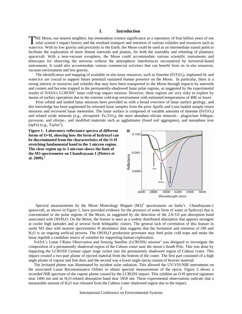
Figure 1. Laboratory reflectance spectra of different
forms of O+H, showing how the form of hydroxyl can
be discriminated from the characteristics of the O-H
stretching fundamental band in the 3 micron region.
The clear region up to 3 microns shows the limit of
the M3 spectrometer on Chandrayaan-1 (Pieters et
al. 2009).3
Spectral measurements by the Moon Mineralogy Mapper (M3)3 spectrometer on India’s Chandrayaan-1
spacecraft, as shown in Figure 1, have provided evidence for the presence of some form of water or hydroxyl that is
concentrated in the polar regions of the Moon, as suggested by the detection of the 2.8-3.0 µm absorption band
associated with OH/H2O. On the Moon, the feature is seen as a widely distributed absorption that appears strongest
at cooler high latitudes and at several fresh feldspathic craters. The general lack of correlation of this feature in
sunlit M3 data with neutron spectrometer H abundance data suggests that the formation and retention of OH and
H2O is an ongoing surficial process. The OH/H2O production processes may feed polar cold traps and make the
lunar regolith a candidate source of volatiles for supporting human exploration.
NASA’s Lunar CRater Observation and Sensing Satellite (LCROSS) mission1
was designed to investigate the
composition of a permanently shadowed region of the Cabeus crater near the moon’s South Pole. This was done by
impacting the LCROSS Centaur upper stage rocket into the permanently shadowed region of Cabeus crater. This
impact created a two-part plume of ejected material from the bottom of the crater. The first part consisted of a high
angle plume of vapour and fine dust, and the second was a lower angle ejecta curtain of heavier material.
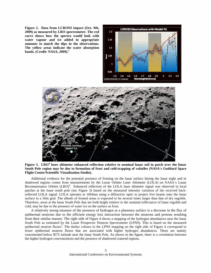
The levitated plume was illuminated by incident solar radiation. This allowed the UV/VIS/NIR instruments on
the associated Lunar Reconnaissance Orbiter to obtain spectral measurements of the ejecta. Figure 2 shows a
recorded NIR spectrum of the vapour plume caused by the LCROSS impact. This exhibits an O-H spectral signature
near 1400 nm and an H2O-related absorption band near 1850 nm. These experimental observations indicate that a
measurable amount of H2O was released from the Cabeus crater shadowed region due to the impact.
T
International Conference on Environmental Systems
3
Figure 2. Data from LCROSS impact (Oct. 9th,
2009) as measured by LRO spectrometer. The red
curve shows how the spectra would look with
water vapour and ice added in appropriate
amounts to match the dips in the observations.
The yellow areas indicate the water absorption
bands. (Credit: NASA, 2009).1
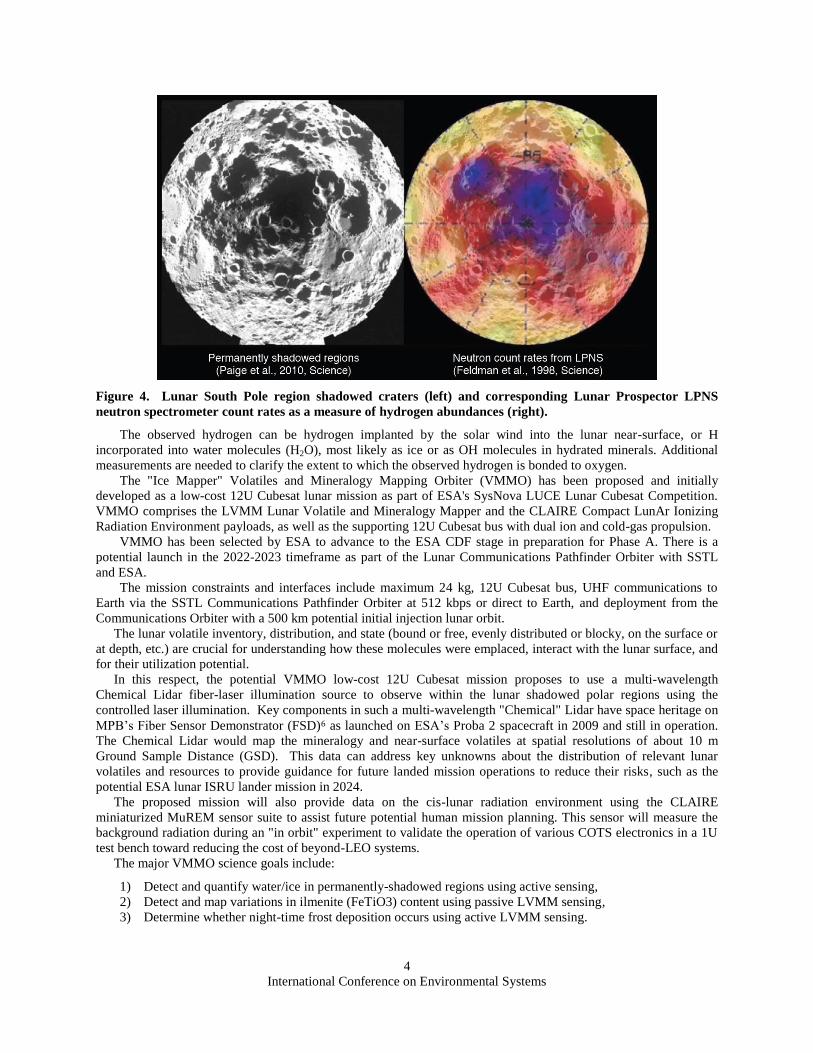
Figure 3. LRO4 laser altimeter enhanced reflection relative to nominal lunar soil in patch over the lunar
South Pole region may be due to formation of frost and cold-trapping of volatiles (NASA's Goddard Space
Flight Center/Scientific Visualization Studio).
Additional evidence for the potential presence of frosting on the lunar surface during the lunar night and in
shadowed regions comes from measurements by the Lunar Orbiter Laser Altimeter (LOLA) on NASA’s Lunar
Reconnaissance Orbiter (LRO)4.
Enhanced reflection of the LOLA laser altimeter signal was observed in local
patches at the lunar south pole (see Figure 3) based on the measured intensity variation of the received back-
reflected LOLA signal. LOLA operates at 1064nm using a diffractive optic to project five beams onto the lunar
surface in a 50m grid. The albedo of frosted areas is expected to be several times larger than that of dry regolith.
Therefore, areas at the lunar South Pole that are both bright relative to the nominal reflectance of lunar regolith and
cold, may be due to the presence of water ice on the surface as frost.
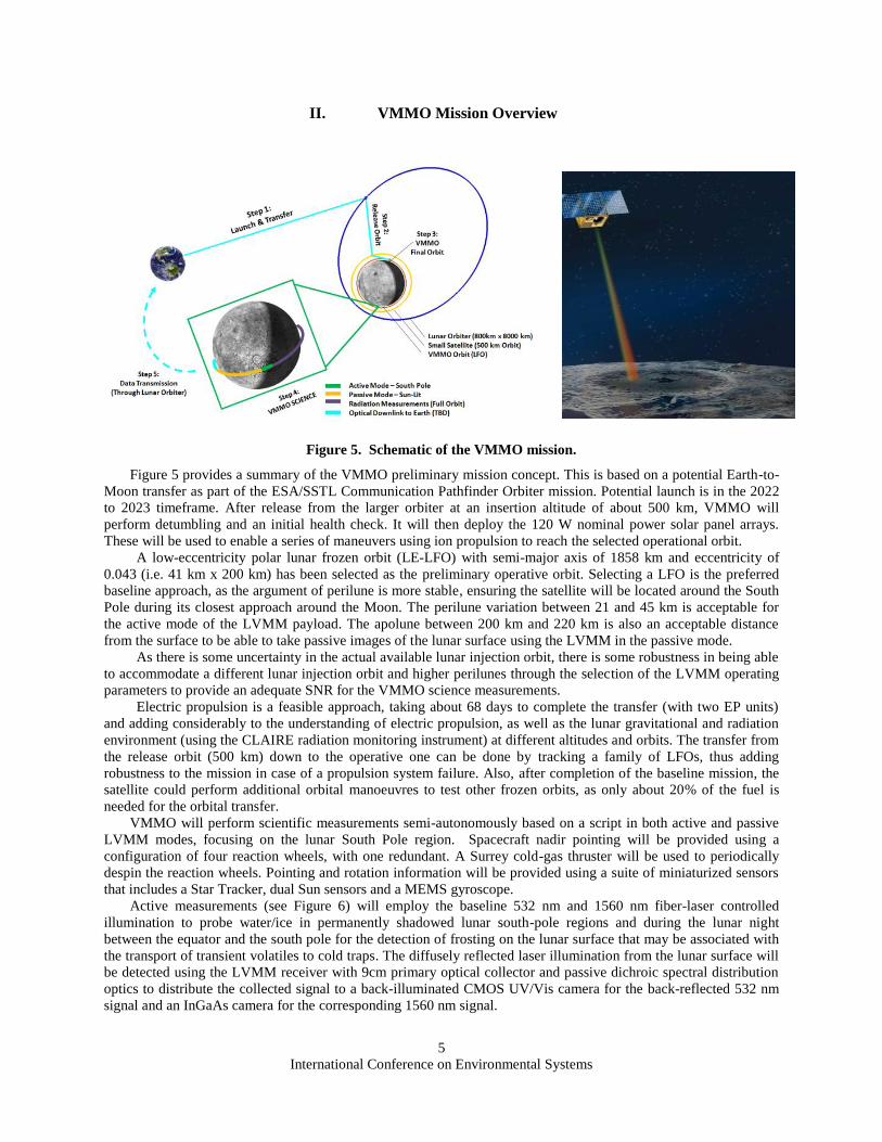
A relatively strong measure of the presence of hydrogen at a planetary surface is a decrease in the flux of
epithermal neutrons due to the efficient energy loss interaction between the neutrons and protons resulting
from their similar masses. The right side of Figure 4 shows a mapping of the hydrogen abundances near the lunar
South Pole as estimated by the Lunar Prospector Neutron Spectrometer (LPNS). This is based on the measured
epithermal neutron fluxes5. The darker colours in the LPNS mapping on the right side of Figure 4 correspond to
lower epithermal neutron fluxes that are associated with higher hydrogen abundances. These are mainly
concentrated below 85oS latitude near the lunar South Pole. As shown in the figure, there is a correlation between
the higher hydrogen concentrations and the presence of shadowed cratered regions.
International Conference on Environmental Systems
4
Figure 4. Lunar South Pole region shadowed craters (left) and corresponding Lunar Prospector LPNS
neutron spectrometer count rates as a measure of hydrogen abundances (right).
The observed hydrogen can be hydrogen implanted by the solar wind into the lunar near-surface, or H
incorporated into water molecules (H2O), most likely as ice or as OH molecules in hydrated minerals. Additional
measurements are needed to clarify the extent to which the observed hydrogen is bonded to oxygen.
The "Ice Mapper" Volatiles and Mineralogy Mapping Orbiter (VMMO) has been proposed and initially
developed as a low-cost 12U Cubesat lunar mission as part of ESA's SysNova LUCE Lunar Cubesat Competition.
VMMO comprises the LVMM Lunar Volatile and Mineralogy Mapper and the CLAIRE Compact LunAr Ionizing
Radiation Environment payloads, as well as the supporting 12U Cubesat bus with dual ion and cold-gas propulsion.
VMMO has been selected by ESA to advance to the ESA CDF stage in preparation for Phase A. There is a
potential launch in the 2022-2023 timeframe as part of the Lunar Communications Pathfinder Orbiter with SSTL
and ESA.
The mission constraints and interfaces include maximum 24 kg, 12U Cubesat bus, UHF communications to
Earth via the SSTL Communications Pathfinder Orbiter at 512 kbps or direct to Earth, and deployment from the
Communications Orbiter with a 500 km potential initial injection lunar orbit.
The lunar volatile inventory, distribution, and state (bound or free, evenly distributed or blocky, on the surface or
at depth, etc.) are crucial for understanding how these molecules were emplaced, interact with the lunar surface, and
for their utilization potential.
In this respect, the potential VMMO low-cost 12U Cubesat mission proposes to use a multi-wavelength
Chemical Lidar fiber-laser illumination source to observe within the lunar shadowed polar regions using the
controlled laser illumination. Key components in such a multi-wavelength "Chemical" Lidar have space heritage on
MPB’s Fiber Sensor Demonstrator (FSD)6 as launched on ESA’s Proba 2 spacecraft in 2009 and still in operation.
The Chemical Lidar would map the mineralogy and near-surface volatiles at spatial resolutions of about 10 m
Ground Sample Distance (GSD). This data can address key unknowns about the distribution of relevant lunar
volatiles and resources to provide guidance for future landed mission operations to reduce their risks, such as the
potential ESA lunar ISRU lander mission in 2024.
The proposed mission will also provide data on the cis-lunar radiation environment using the CLAIRE
miniaturized MuREM sensor suite to assist future potential human mission planning. This sensor will measure the
background radiation during an "in orbit" experiment to validate the operation of various COTS electronics in a 1U
test bench toward reducing the cost of beyond-LEO systems.
The major VMMO science goals include:
1) Detect and quantify water/ice in permanently-shadowed regions using active sensing,
2) Detect and map variations in ilmenite (FeTiO3) content using passive LVMM sensing,
3) Determine whether night-time frost deposition occurs using active LVMM sensing.
International Conference on Environmental Systems
5
II. VMMO Mission Overview
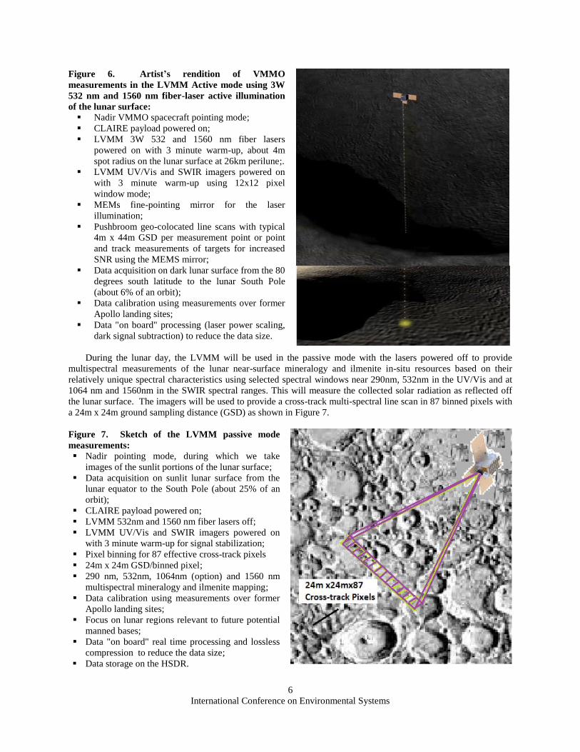
Figure 5. Schematic of the VMMO mission.
Figure 5 provides a summary of the VMMO preliminary mission concept. This is based on a potential Earth-to-
Moon transfer as part of the ESA/SSTL Communication Pathfinder Orbiter mission. Potential launch is in the 2022
to 2023 timeframe. After release from the larger orbiter at an insertion altitude of about 500 km, VMMO will
perform detumbling and an initial health check. It will then deploy the 120 W nominal power solar panel arrays.
These will be used to enable a series of maneuvers using ion propulsion to reach the selected operational orbit.
A low-eccentricity polar lunar frozen orbit (LE-LFO) with semi-major axis of 1858 km and eccentricity of
0.043 (i.e. 41 km x 200 km) has been selected as the preliminary operative orbit. Selecting a LFO is the preferred
baseline approach, as the argument of perilune is more stable, ensuring the satellite will be located around the South
Pole during its closest approach around the Moon. The perilune variation between 21 and 45 km is acceptable for
the active mode of the LVMM payload. The apolune between 200 km and 220 km is also an acceptable distance
from the surface to be able to take passive images of the lunar surface using the LVMM in the passive mode.
As there is some uncertainty in the actual available lunar injection orbit, there is some robustness in being able
to accommodate a different lunar injection orbit and higher perilunes through the selection of the LVMM operating
parameters to provide an adequate SNR for the VMMO science measurements.
Electric propulsion is a feasible approach, taking about 68 days to complete the transfer (with two EP units)
and adding considerably to the understanding of electric propulsion, as well as the lunar gravitational and radiation
environment (using the CLAIRE radiation monitoring instrument) at different altitudes and orbits. The transfer from
the release orbit (500 km) down to the operative one can be done by tracking a family of LFOs, thus adding
robustness to the mission in case of a propulsion system failure. Also, after completion of the baseline mission, the
satellite could perform additional orbital manoeuvres to test other frozen orbits, as only about 20% of the fuel is
needed for the orbital transfer.
VMMO will perform scientific measurements semi-autonomously based on a script in both active and passive
LVMM modes, focusing on the lunar South Pole region. Spacecraft nadir pointing will be provided using a
configuration of four reaction wheels, with one redundant. A Surrey cold-gas thruster will be used to periodically
despin the reaction wheels. Pointing and rotation information will be provided using a suite of miniaturized sensors
that includes a Star Tracker, dual Sun sensors and a MEMS gyroscope.
Active measurements (see Figure 6) will employ the baseline 532 nm and 1560 nm fiber-laser controlled
illumination to probe water/ice in permanently shadowed lunar south-pole regions and during the lunar night
between the equator and the south pole for the detection of frosting on the lunar surface that may be associated with
the transport of transient volatiles to cold traps. The diffusely reflected laser illumination from the lunar surface will
be detected using the LVMM receiver with 9cm primary optical collector and passive dichroic spectral distribution
optics to distribute the collected signal to a back-illuminated CMOS UV/Vis camera for the back-reflected 532 nm
signal and an InGaAs camera for the corresponding 1560 nm signal.
International Conference on Environmental Systems
6
Figure 6. Artist’s rendition of VMMO
measurements in the LVMM Active mode using 3W
532 nm and 1560 nm fiber-laser active illumination
of the lunar surface:
Nadir VMMO spacecraft pointing mode;
CLAIRE payload powered on;
LVMM 3W 532 and 1560 nm fiber lasers
powered on with 3 minute warm-up, about 4m
spot radius on the lunar surface at 26km perilune;.
LVMM UV/Vis and SWIR imagers powered on
with 3 minute warm-up using 12x12 pixel
window mode;
MEMs fine-pointing mirror for the laser
illumination;
Pushbroom geo-colocated line scans with typical
4m x 44m GSD per measurement point or point
and track measurements of targets for increased
SNR using the MEMS mirror;
Data acquisition on dark lunar surface from the 80
degrees south latitude to the lunar South Pole
(about 6% of an orbit);
Data calibration using measurements over former
Apollo landing sites;
Data "on board" processing (laser power scaling,
dark signal subtraction) to reduce the data size.
During the lunar day, the LVMM will be used in the passive mode with the lasers powered off to provide
multispectral measurements of the lunar near-surface mineralogy and ilmenite in-situ resources based on their
relatively unique spectral characteristics using selected spectral windows near 290nm, 532nm in the UV/Vis and at
1064 nm and 1560nm in the SWIR spectral ranges. This will measure the collected solar radiation as reflected off
the lunar surface. The imagers will be used to provide a cross-track multi-spectral line scan in 87 binned pixels with
a 24m x 24m ground sampling distance (GSD) as shown in Figure 7.
Figure 7. Sketch of the LVMM passive mode
measurements:
Nadir pointing mode, during which we take
images of the sunlit portions of the lunar surface;
Data acquisition on sunlit lunar surface from the
lunar equator to the South Pole (about 25% of an
orbit);
CLAIRE payload powered on;
LVMM 532nm and 1560 nm fiber lasers off;
LVMM UV/Vis and SWIR imagers powered on
with 3 minute warm-up for signal stabilization;
Pixel binning for 87 effective cross-track pixels
24m x 24m GSD/binned pixel;
290 nm, 532nm, 1064nm (option) and 1560 nm
multispectral mineralogy and ilmenite mapping;
Data calibration using measurements over former
Apollo landing sites;
Focus on lunar regions relevant to future potential
manned bases;
Data "on board" real time processing and lossless
compression to reduce the data size;
Data storage on the HSDR.
International Conference on Environmental Systems
7
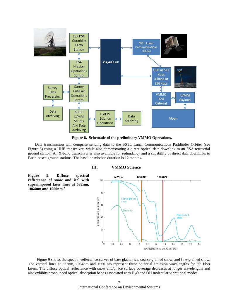
Figure 8. Schematic of the preliminary VMMO Operations.
Data transmission will comprise sending data to the SSTL Lunar Communications Pathfinder Orbiter (see
Figure 8) using a UHF transceiver, while also demonstrating a direct optical data downlink to an ESA terrestrial
ground station. An X-band transceiver is also available for redundancy and a capability of direct data downlinks to
Earth-based ground stations. The baseline mission duration is 12 months.
III. VMMO Science
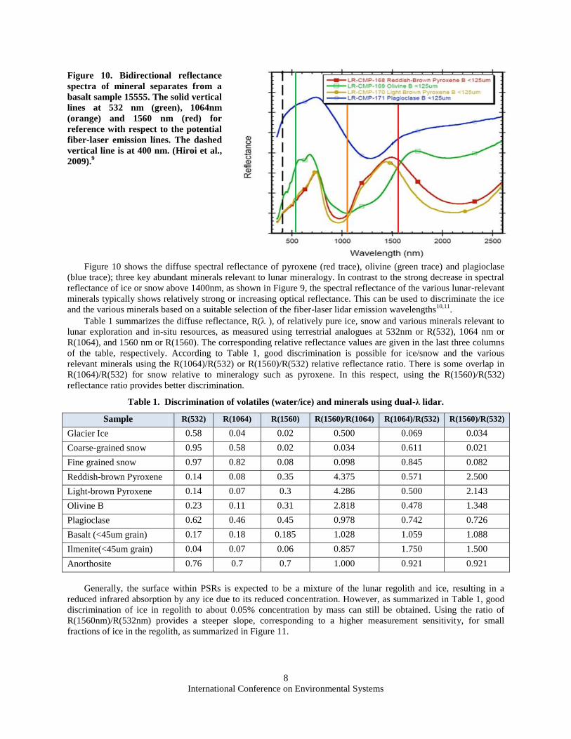
Figure 9. Diffuse spectral
reflectance of snow and ice8
with
superimposed laser lines at 532nm,
1064nm and 1560nm.8
Figure 9 shows the spectral-reflectance curves of bare glacier ice, coarse-grained snow, and fine-grained snow.
The vertical lines at 532nm, 1064nm and 1560 nm represent three potential emission wavelengths for the fiber
lasers. The diffuse optical reflectance with snow and/or ice surface coverage decreases at longer wavelengths and
also exhibits pronounced optical absorption bands associated with H2O and OH molecular vibrational modes.
International Conference on Environmental Systems
8
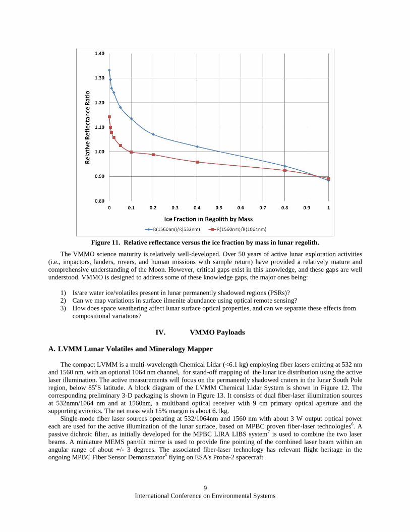
Figure 10. Bidirectional reflectance
spectra of mineral separates from a
basalt sample 15555. The solid vertical
lines at 532 nm (green), 1064nm
(orange) and 1560 nm (red) for
reference with respect to the potential
fiber-laser emission lines. The dashed
vertical line is at 400 nm. (Hiroi et al.,
2009).9
Figure 10 shows the diffuse spectral reflectance of pyroxene (red trace), olivine (green trace) and plagioclase
(blue trace); three key abundant minerals relevant to lunar mineralogy. In contrast to the strong decrease in spectral
reflectance of ice or snow above 1400nm, as shown in Figure 9, the spectral reflectance of the various lunar-relevant
minerals typically shows relatively strong or increasing optical reflectance. This can be used to discriminate the ice
and the various minerals based on a suitable selection of the fiber-laser lidar emission wavelengths10,11
.
Table 1 summarizes the diffuse reflectance, R( ), of relatively pure ice, snow and various minerals relevant to
lunar exploration and in-situ resources, as measured using terrestrial analogues at 532nm or R(532), 1064 nm or
R(1064), and 1560 nm or R(1560). The corresponding relative reflectance values are given in the last three columns
of the table, respectively. According to Table 1, good discrimination is possible for ice/snow and the various
relevant minerals using the R(1064)/R(532) or R(1560)/R(532) relative reflectance ratio. There is some overlap in
R(1064)/R(532) for snow relative to mineralogy such as pyroxene. In this respect, using the R(1560)/R(532)
reflectance ratio provides better discrimination.
Table 1. Discrimination of volatiles (water/ice) and minerals using dual-λ lidar.
Sample R(532) R(1064) R(1560) R(1560)/R(1064) R(1064)/R(532) R(1560)/R(532)
Glacier Ice 0.58 0.04 0.02 0.500 0.069 0.034
Coarse-grained snow 0.95 0.58 0.02 0.034 0.611 0.021
Fine grained snow 0.97 0.82 0.08 0.098 0.845 0.082
Reddish-brown Pyroxene 0.14 0.08 0.35 4.375 0.571 2.500
Light-brown Pyroxene 0.14 0.07 0.3 4.286 0.500 2.143
Olivine B 0.23 0.11 0.31 2.818 0.478 1.348
Plagioclase 0.62 0.46 0.45 0.978 0.742 0.726
Basalt (<45um grain) 0.17 0.18 0.185 1.028 1.059 1.088
Ilmenite(<45um grain) 0.04 0.07 0.06 0.857 1.750 1.500
Anorthosite 0.76 0.7 0.7 1.000 0.921 0.921
Generally, the surface within PSRs is expected to be a mixture of the lunar regolith and ice, resulting in a
reduced infrared absorption by any ice due to its reduced concentration. However, as summarized in Table 1, good
discrimination of ice in regolith to about 0.05% concentration by mass can still be obtained. Using the ratio of
R(1560nm)/R(532nm) provides a steeper slope, corresponding to a higher measurement sensitivity, for small
fractions of ice in the regolith, as summarized in Figure 11.
International Conference on Environmental Systems
9
Figure 11. Relative reflectance versus the ice fraction by mass in lunar regolith.
The VMMO science maturity is relatively well-developed. Over 50 years of active lunar exploration activities
(i.e., impactors, landers, rovers, and human missions with sample return) have provided a relatively mature and
comprehensive understanding of the Moon. However, critical gaps exist in this knowledge, and these gaps are well
understood. VMMO is designed to address some of these knowledge gaps, the major ones being:
1) Is/are water ice/volatiles present in lunar permanently shadowed regions (PSRs)?
2) Can we map variations in surface ilmenite abundance using optical remote sensing?
3) How does space weathering affect lunar surface optical properties, and can we separate these effects from
compositional variations?
IV. VMMO Payloads
A. LVMM Lunar Volatiles and Mineralogy Mapper
The compact LVMM is a multi-wavelength Chemical Lidar (<6.1 kg) employing fiber lasers emitting at 532 nm
and 1560 nm, with an optional 1064 nm channel, for stand-off mapping of the lunar ice distribution using the active
laser illumination. The active measurements will focus on the permanently shadowed craters in the lunar South Pole
region, below 85oS latitude. A block diagram of the LVMM Chemical Lidar System is shown in Figure 12. The
corresponding preliminary 3-D packaging is shown in Figure 13. It consists of dual fiber-laser illumination sources
at 532nmn/1064 nm and at 1560nm, a multiband optical receiver with 9 cm primary optical aperture and the
supporting avionics. The net mass with 15% margin is about 6.1kg.
Single-mode fiber laser sources operating at 532/1064nm and 1560 nm with about 3 W output optical power
each are used for the active illumination of the lunar surface, based on MPBC proven fiber-laser technologies6. A
passive dichroic filter, as initially developed for the MPBC LIRA LIBS system7 is used to combine the two laser
beams. A miniature MEMS pan/tilt mirror is used to provide fine pointing of the combined laser beam within an
angular range of about +/- 3 degrees. The associated fiber-laser technology has relevant flight heritage in the
ongoing MPBC Fiber Sensor Demonstrator6 flying on ESA's Proba-2 spacecraft.
International Conference on Environmental Systems
10
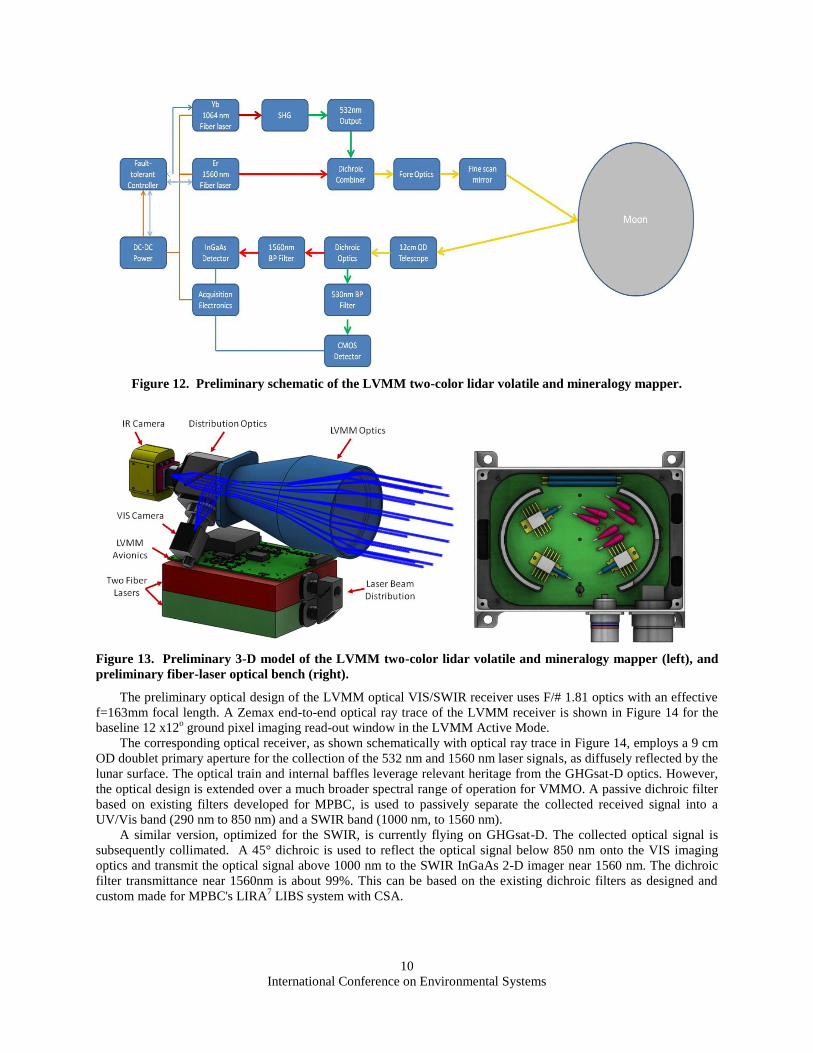
Figure 12. Preliminary schematic of the LVMM two-color lidar volatile and mineralogy mapper.
Figure 13. Preliminary 3-D model of the LVMM two-color lidar volatile and mineralogy mapper (left), and
preliminary fiber-laser optical bench (right).
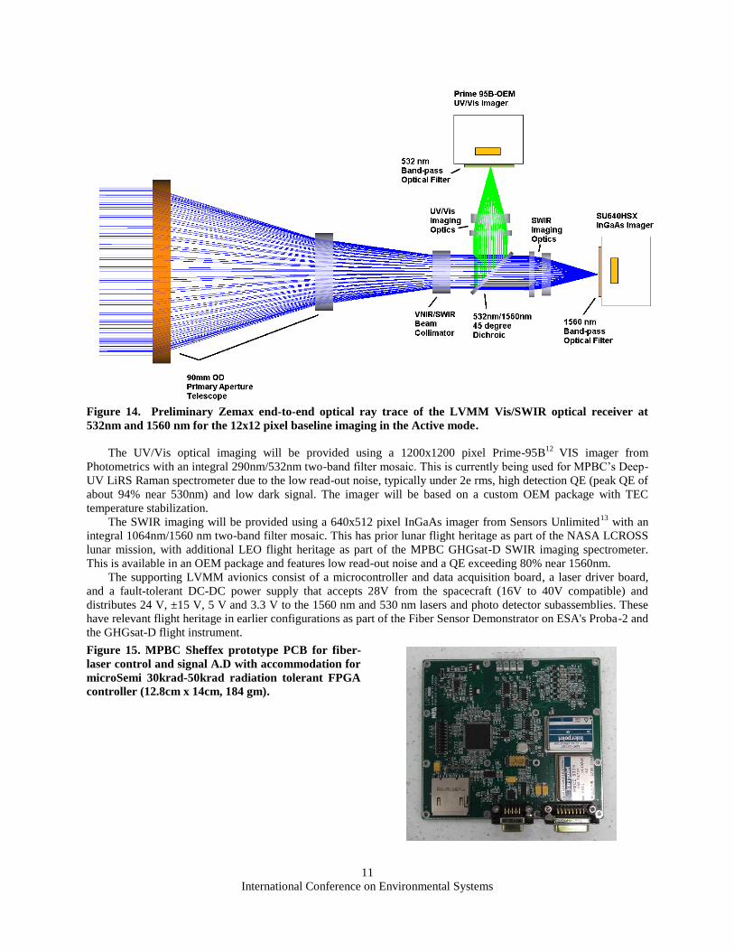
The preliminary optical design of the LVMM optical VIS/SWIR receiver uses F/# 1.81 optics with an effective
f=163mm focal length. A Zemax end-to-end optical ray trace of the LVMM receiver is shown in Figure 14 for the
baseline 12 x12o ground pixel imaging read-out window in the LVMM Active Mode.
The corresponding optical receiver, as shown schematically with optical ray trace in Figure 14, employs a 9 cm
OD doublet primary aperture for the collection of the 532 nm and 1560 nm laser signals, as diffusely reflected by the
lunar surface. The optical train and internal baffles leverage relevant heritage from the GHGsat-D optics. However,
the optical design is extended over a much broader spectral range of operation for VMMO. A passive dichroic filter
based on existing filters developed for MPBC, is used to passively separate the collected received signal into a
UV/Vis band (290 nm to 850 nm) and a SWIR band (1000 nm, to 1560 nm).
A similar version, optimized for the SWIR, is currently flying on GHGsat-D. The collected optical signal is
subsequently collimated. A 45° dichroic is used to reflect the optical signal below 850 nm onto the VIS imaging
optics and transmit the optical signal above 1000 nm to the SWIR InGaAs 2-D imager near 1560 nm. The dichroic
filter transmittance near 1560nm is about 99%. This can be based on the existing dichroic filters as designed and
custom made for MPBC's LIRA7 LIBS system with CSA.
International Conference on Environmental Systems
11
Figure 14. Preliminary Zemax end-to-end optical ray trace of the LVMM Vis/SWIR optical receiver at
532nm and 1560 nm for the 12x12 pixel baseline imaging in the Active mode.
The UV/Vis optical imaging will be provided using a 1200x1200 pixel Prime-95B12
VIS imager from
Photometrics with an integral 290nm/532nm two-band filter mosaic. This is currently being used for MPBC’s Deep-
UV LiRS Raman spectrometer due to the low read-out noise, typically under 2e rms, high detection QE (peak QE of
about 94% near 530nm) and low dark signal. The imager will be based on a custom OEM package with TEC
temperature stabilization.
The SWIR imaging will be provided using a 640x512 pixel InGaAs imager from Sensors Unlimited13
with an
integral 1064nm/1560 nm two-band filter mosaic. This has prior lunar flight heritage as part of the NASA LCROSS
lunar mission, with additional LEO flight heritage as part of the MPBC GHGsat-D SWIR imaging spectrometer.
This is available in an OEM package and features low read-out noise and a QE exceeding 80% near 1560nm.
The supporting LVMM avionics consist of a microcontroller and data acquisition board, a laser driver board,
and a fault-tolerant DC-DC power supply that accepts 28V from the spacecraft (16V to 40V compatible) and
distributes 24 V, ±15 V, 5 V and 3.3 V to the 1560 nm and 530 nm lasers and photo detector subassemblies. These
have relevant flight heritage in earlier configurations as part of the Fiber Sensor Demonstrator on ESA's Proba-2 and
the GHGsat-D flight instrument.
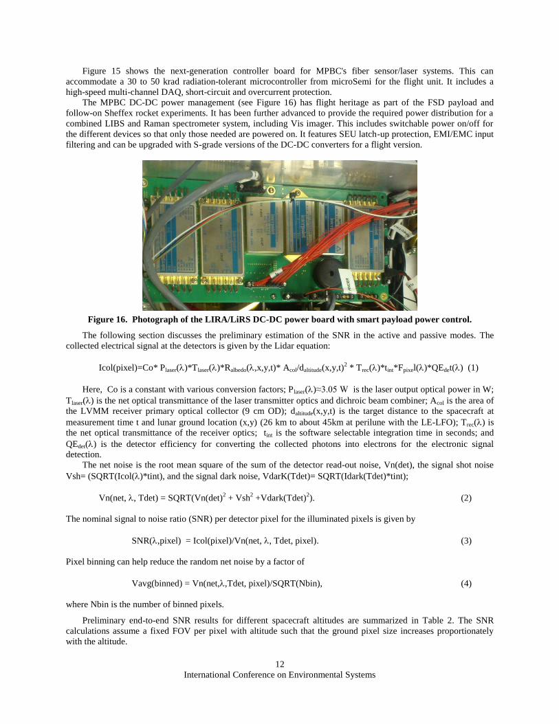
Figure 15. MPBC Sheffex prototype PCB for fiber-
laser control and signal A.D with accommodation for
microSemi 30krad-50krad radiation tolerant FPGA
controller (12.8cm x 14cm, 184 gm).
International Conference on Environmental Systems
12
Figure 15 shows the next-generation controller board for MPBC's fiber sensor/laser systems. This can
accommodate a 30 to 50 krad radiation-tolerant microcontroller from microSemi for the flight unit. It includes a
high-speed multi-channel DAQ, short-circuit and overcurrent protection.
The MPBC DC-DC power management (see Figure 16) has flight heritage as part of the FSD payload and
follow-on Sheffex rocket experiments. It has been further advanced to provide the required power distribution for a
combined LIBS and Raman spectrometer system, including Vis imager. This includes switchable power on/off for
the different devices so that only those needed are powered on. It features SEU latch-up protection, EMI/EMC input
filtering and can be upgraded with S-grade versions of the DC-DC converters for a flight version.
Figure 16. Photograph of the LIRA/LiRS DC-DC power board with smart payload power control.
The following section discusses the preliminary estimation of the SNR in the active and passive modes. The
collected electrical signal at the detectors is given by the Lidar equation:
Icol(pixel)=Co* Plaser()*Tlaser()*Ralbedo(,x,y,t)* Acol/daltitude(x,y,t)2 * Trec()*tint*Fpixel()*QEdet() (1)
Here, Co is a constant with various conversion factors; Plaser()≈3.05 W is the laser output optical power in W;
Tlaser() is the net optical transmittance of the laser transmitter optics and dichroic beam combiner; Acol is the area of
the LVMM receiver primary optical collector (9 cm OD); daltitude(x,y,t) is the target distance to the spacecraft at
measurement time t and lunar ground location (x,y) (26 km to about 45km at perilune with the LE-LFO); Trec() is
the net optical transmittance of the receiver optics; tint is the software selectable integration time in seconds; and
QEdet() is the detector efficiency for converting the collected photons into electrons for the electronic signal
detection.
The net noise is the root mean square of the sum of the detector read-out noise, Vn(det), the signal shot noise
Vsh= (SQRT(Icol()*tint), and the signal dark noise, VdarK(Tdet)= SQRT(Idark(Tdet)*tint);
Vn(net, , Tdet) = SQRT(Vn(det)2 + Vsh
2 +Vdark(Tdet)
2). (2)
The nominal signal to noise ratio (SNR) per detector pixel for the illuminated pixels is given by
SNR(,pixel) = Icol(pixel)/Vn(net, , Tdet, pixel). (3)
Pixel binning can help reduce the random net noise by a factor of
Vavg(binned) = Vn(net,,Tdet, pixel)/SQRT(Nbin), (4)
where Nbin is the number of binned pixels.
Preliminary end-to-end SNR results for different spacecraft altitudes are summarized in Table 2. The SNR
calculations assume a fixed FOV per pixel with altitude such that the ground pixel size increases proportionately
with the altitude.
International Conference on Environmental Systems
13
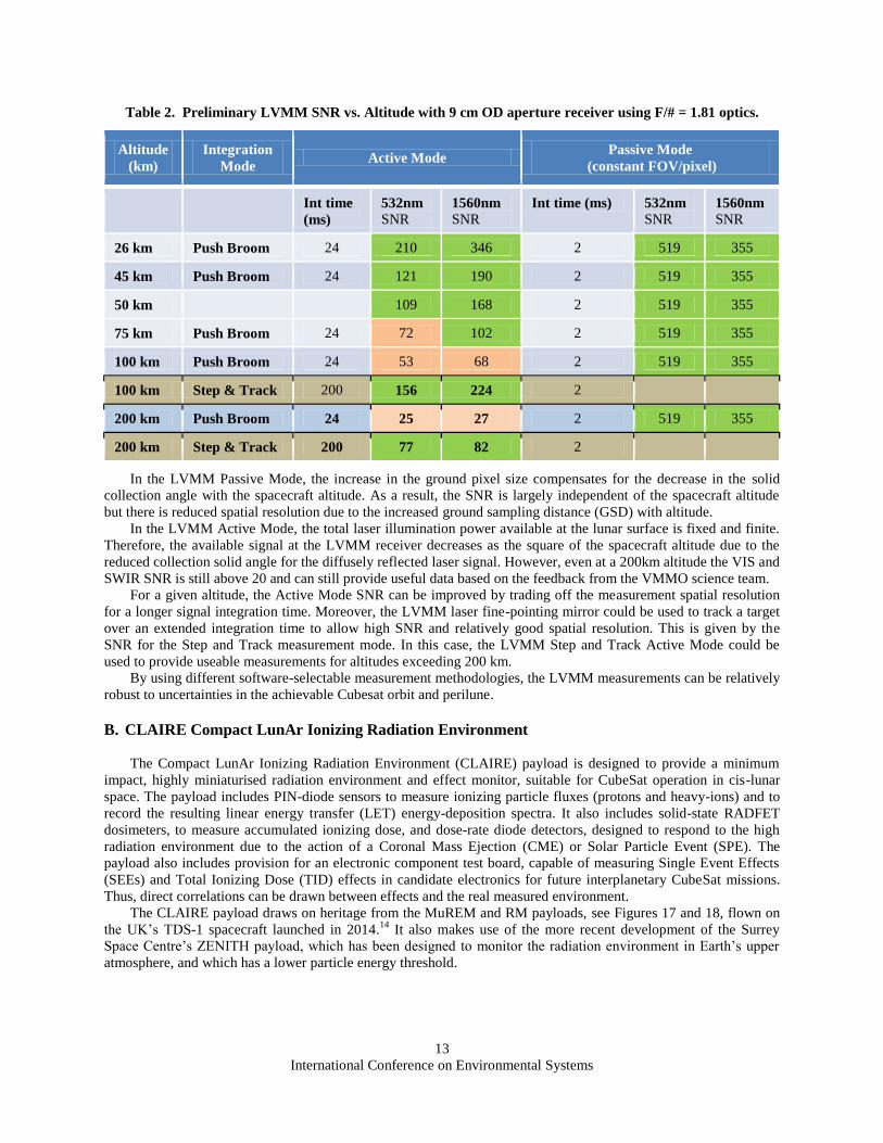
Table 2. Preliminary LVMM SNR vs. Altitude with 9 cm OD aperture receiver using F/# = 1.81 optics.
Altitude
(km)
Integration
Mode Active Mode
Passive Mode
(constant FOV/pixel)
Int time
(ms)
532nm SNR
1560nm SNR
Int time (ms) 532nm SNR
1560nm SNR
26 km Push Broom 24 210 346 2 519 355
45 km Push Broom 24 121 190 2 519 355
50 km 109 168 2 519 355
75 km Push Broom 24 72 102 2 519 355
100 km Push Broom 24 53 68 2 519 355
100 km Step & Track 200 156 224 2
200 km Push Broom 24 25 27 2 519 355
200 km Step & Track 200 77 82 2
In the LVMM Passive Mode, the increase in the ground pixel size compensates for the decrease in the solid
collection angle with the spacecraft altitude. As a result, the SNR is largely independent of the spacecraft altitude
but there is reduced spatial resolution due to the increased ground sampling distance (GSD) with altitude.
In the LVMM Active Mode, the total laser illumination power available at the lunar surface is fixed and finite.
Therefore, the available signal at the LVMM receiver decreases as the square of the spacecraft altitude due to the
reduced collection solid angle for the diffusely reflected laser signal. However, even at a 200km altitude the VIS and
SWIR SNR is still above 20 and can still provide useful data based on the feedback from the VMMO science team.
For a given altitude, the Active Mode SNR can be improved by trading off the measurement spatial resolution
for a longer signal integration time. Moreover, the LVMM laser fine-pointing mirror could be used to track a target
over an extended integration time to allow high SNR and relatively good spatial resolution. This is given by the
SNR for the Step and Track measurement mode. In this case, the LVMM Step and Track Active Mode could be
used to provide useable measurements for altitudes exceeding 200 km.
By using different software-selectable measurement methodologies, the LVMM measurements can be relatively
robust to uncertainties in the achievable Cubesat orbit and perilune.
B. CLAIRE Compact LunAr Ionizing Radiation Environment
The Compact LunAr Ionizing Radiation Environment (CLAIRE) payload is designed to provide a minimum
impact, highly miniaturised radiation environment and effect monitor, suitable for CubeSat operation in cis-lunar
space. The payload includes PIN-diode sensors to measure ionizing particle fluxes (protons and heavy-ions) and to
record the resulting linear energy transfer (LET) energy-deposition spectra. It also includes solid-state RADFET
dosimeters, to measure accumulated ionizing dose, and dose-rate diode detectors, designed to respond to the high
radiation environment due to the action of a Coronal Mass Ejection (CME) or Solar Particle Event (SPE). The
payload also includes provision for an electronic component test board, capable of measuring Single Event Effects
(SEEs) and Total Ionizing Dose (TID) effects in candidate electronics for future interplanetary CubeSat missions.
Thus, direct correlations can be drawn between effects and the real measured environment.
The CLAIRE payload draws on heritage from the MuREM and RM payloads, see Figures 17 and 18, flown on
the UK’s TDS-1 spacecraft launched in 2014.14
It also makes use of the more recent development of the Surrey
Space Centre’s ZENITH payload, which has been designed to monitor the radiation environment in Earth’s upper
atmosphere, and which has a lower particle energy threshold.
International Conference on Environmental Systems
14
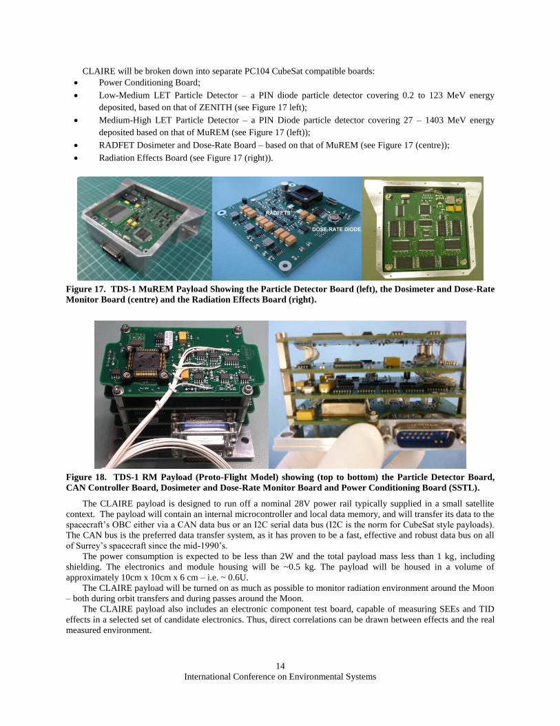
CLAIRE will be broken down into separate PC104 CubeSat compatible boards:
Power Conditioning Board;
Low-Medium LET Particle Detector – a PIN diode particle detector covering 0.2 to 123 MeV energy
deposited, based on that of ZENITH (see Figure 17 left);
Medium-High LET Particle Detector – a PIN Diode particle detector covering 27 – 1403 MeV energy
deposited based on that of MuREM (see Figure 17 (left));
RADFET Dosimeter and Dose-Rate Board – based on that of MuREM (see Figure 17 (centre));
Radiation Effects Board (see Figure 17 (right)).
Figure 17. TDS-1 MuREM Payload Showing the Particle Detector Board (left), the Dosimeter and Dose-Rate
Monitor Board (centre) and the Radiation Effects Board (right).
Figure 18. TDS-1 RM Payload (Proto-Flight Model) showing (top to bottom) the Particle Detector Board,
CAN Controller Board, Dosimeter and Dose-Rate Monitor Board and Power Conditioning Board (SSTL).
The CLAIRE payload is designed to run off a nominal 28V power rail typically supplied in a small satellite
context. The payload will contain an internal microcontroller and local data memory, and will transfer its data to the
spacecraft’s OBC either via a CAN data bus or an I2C serial data bus (I2C is the norm for CubeSat style payloads).
The CAN bus is the preferred data transfer system, as it has proven to be a fast, effective and robust data bus on all
of Surrey’s spacecraft since the mid-1990’s.
The power consumption is expected to be less than 2W and the total payload mass less than 1 kg, including
shielding. The electronics and module housing will be ~0.5 kg. The payload will be housed in a volume of
approximately 10cm x 10cm x 6 cm – i.e. ~ 0.6U.
The CLAIRE payload will be turned on as much as possible to monitor radiation environment around the Moon
– both during orbit transfers and during passes around the Moon.
The CLAIRE payload also includes an electronic component test board, capable of measuring SEEs and TID
effects in a selected set of candidate electronics. Thus, direct correlations can be drawn between effects and the real
measured environment.
International Conference on Environmental Systems
15
V. Preliminary VMMO 12U Cubesat Architecture
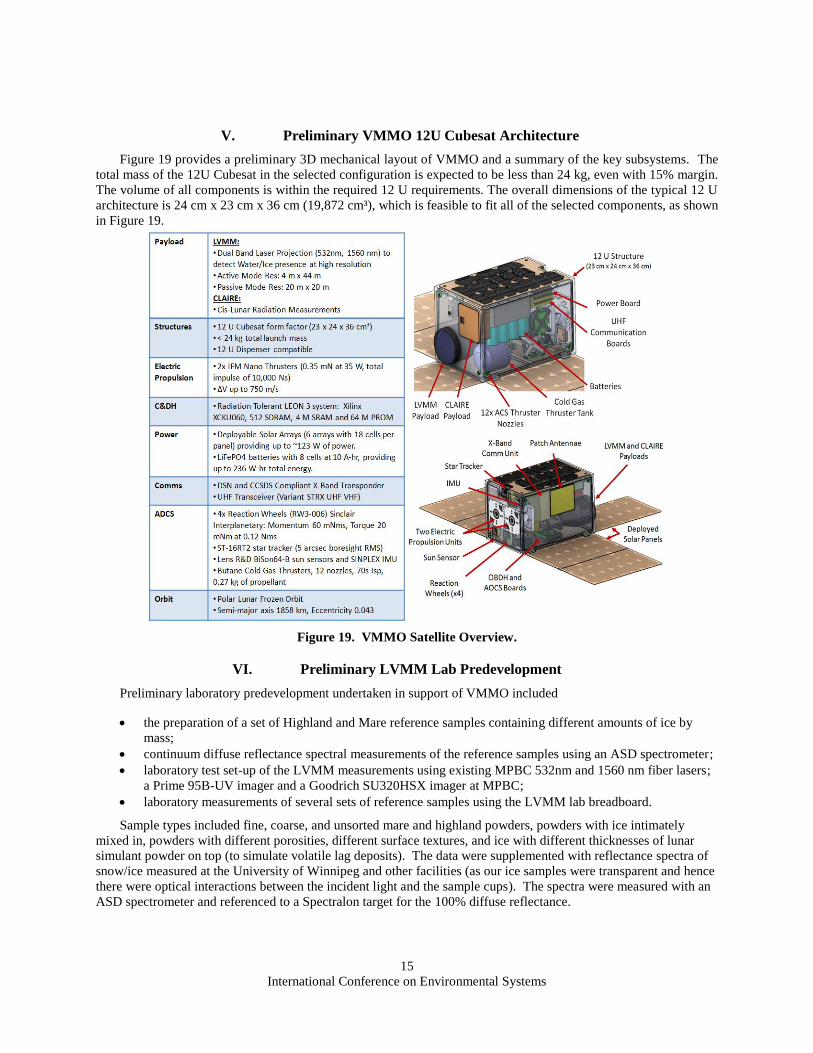
Figure 19 provides a preliminary 3D mechanical layout of VMMO and a summary of the key subsystems. The
total mass of the 12U Cubesat in the selected configuration is expected to be less than 24 kg, even with 15% margin.
The volume of all components is within the required 12 U requirements. The overall dimensions of the typical 12 U
architecture is 24 cm x 23 cm x 36 cm (19,872 cm³), which is feasible to fit all of the selected components, as shown
in Figure 19.
Figure 19. VMMO Satellite Overview.
VI. Preliminary LVMM Lab Predevelopment
Preliminary laboratory predevelopment undertaken in support of VMMO included
the preparation of a set of Highland and Mare reference samples containing different amounts of ice by
mass;
continuum diffuse reflectance spectral measurements of the reference samples using an ASD spectrometer;
laboratory test set-up of the LVMM measurements using existing MPBC 532nm and 1560 nm fiber lasers;
a Prime 95B-UV imager and a Goodrich SU320HSX imager at MPBC;
laboratory measurements of several sets of reference samples using the LVMM lab breadboard.
Sample types included fine, coarse, and unsorted mare and highland powders, powders with ice intimately
mixed in, powders with different porosities, different surface textures, and ice with different thicknesses of lunar
simulant powder on top (to simulate volatile lag deposits). The data were supplemented with reflectance spectra of
snow/ice measured at the University of Winnipeg and other facilities (as our ice samples were transparent and hence
there were optical interactions between the incident light and the sample cups). The spectra were measured with an
ASD spectrometer and referenced to a Spectralon target for the 100% diffuse reflectance.
International Conference on Environmental Systems
16
C. Reference lab spectra
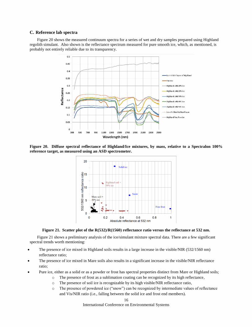
Figure 20 shows the measured continuum spectra for a series of wet and dry samples prepared using Highland
regolith simulant. Also shown is the reflectance spectrum measured for pure smooth ice, which, as mentioned, is
probably not entirely reliable due to its transparency.
Figure 20. Diffuse spectral reflectance of Highland/Ice mixtures, by mass, relative to a Spectralon 100%
reference target, as measured using an ASD spectrometer.
Figure 21. Scatter plot of the R(532)/R(1560) reflectance ratio versus the reflectance at 532 nm.
Figure 21 shows a preliminary analysis of the ice/simulant mixture spectral data. There are a few significant
spectral trends worth mentioning:
The presence of ice mixed in Highland soils results in a large increase in the visible/NIR (532/1560 nm)
reflectance ratio;
The presence of ice mixed in Mare soils also results in a significant increase in the visible/NIR reflectance
ratio;
Pure ice, either as a solid or as a powder or frost has spectral properties distinct from Mare or Highland soils;
o The presence of frost as a sublimation coating can be recognized by its high reflectance,
o The presence of soil ice is recognizable by its high visible/NIR reflectance ratio,
o The presence of powdered ice (“snow”) can be recognized by intermediate values of reflectance
and Vis/NIR ratio (i.e., falling between the solid ice and frost end members).
International Conference on Environmental Systems
17
The spectral changes due to the presence of ice are related to its broad absorption bands near 1500 nm and 1950
nm. The reference spectra in Figure 20 suggest that shifting the 1560 nm LVMM Chemical Lidar channel closer to
1500 nm, i.e., closer to the centre of the strong H2O absorption band, can further improve the measurement
sensitivity for water/ice in the ice/regolith mixtures. In this respect, operation of the Er-doped fiber laser to about
1520nm at the shorter wavelengths is feasible.
D. Water/Ice mapping
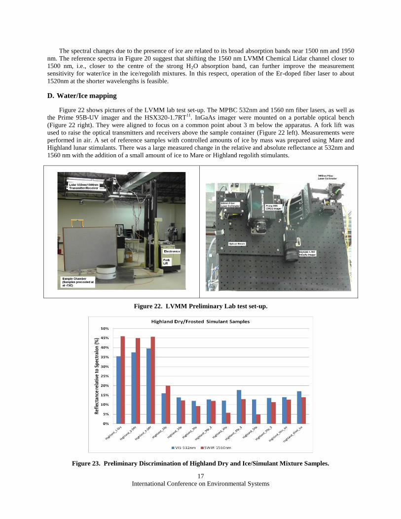
Figure 22 shows pictures of the LVMM lab test set-up. The MPBC 532nm and 1560 nm fiber lasers, as well as
the Prime 95B-UV imager and the HSX320-1.7RT11
. InGaAs imager were mounted on a portable optical bench
(Figure 22 right). They were aligned to focus on a common point about 3 m below the apparatus. A fork lift was
used to raise the optical transmitters and receivers above the sample container (Figure 22 left). Measurements were
performed in air. A set of reference samples with controlled amounts of ice by mass was prepared using Mare and
Highland lunar stimulants. There was a large measured change in the relative and absolute reflectance at 532nm and
1560 nm with the addition of a small amount of ice to Mare or Highland regolith stimulants.
Figure 22. LVMM Preliminary Lab test set-up.
Figure 23. Preliminary Discrimination of Highland Dry and Ice/Simulant Mixture Samples.
International Conference on Environmental Systems
18
Figure 23 summarizes the resulting measured reflectance at 532nm and 1560 nm for a set of Highland dry and
ice/simulant mixtures using the LVMM lab bread board. The following observations can be noted for the
preliminary measurements with wet samples. Ice and frost are spectrally distinct from lunar regolith. The addition of
ice to the regolith causes large and systematic spectral changes. In particular, using the combination of the 532 and
1560 nm spectral regions can provide high-sensitivity to water ice presence in the regolith:
• With increasing ice content:
o 532 nm reflectance increases,
o 1560 nm reflectance decreases,
o 1560/532 nm reflectance ratio decreases.
• Laboratory studies have shown that water/ice detection limit is better than 1%.
• Sample morphology and packing affects the diffuse reflectance.
• Small ice content can produce a large change in the absolute reflectance.
• Need to monitor R(532nm), R(1560nm) and R(532nm)/R(1560nm).
As shown in Table 3, there is a relatively good correlation between the ice fraction in the regolith/ice fraction
and R(1560)/R(532) or R(1520)/R(532). There is also very good differentiation between the Mare and Highland
regolith simulants based on their absolute reflectance at 532 nm and 1560 nm. As noted for the Highland/Ice
mixtures, using R(1520)/R(532) provides a slightly larger variation in the relative reflectance ratios as compared to
R(1560)/R(532).
Table 3. Reference reflectance lab data for Mare/Ice Mixtures at 532 nm, 1064 nm, 1520 nm and 1560 nm.
Mare Simulant 532nm 1064 nm 1520 nm 1560 nm R(1560)/R(532) R(1520)/R(532)
Ice 0.196 0.192 0.119 0.122 0.635 0.607
Ice + thin Mare 0.071 0.079 0.093 0.094 1.190 1.310
Ice + thick Mare 0.029 0.029 0.03 0.03 1.034 1.034
Dry Mare 0.078 0.09 0.118 0.119 1.322 1.513
10% Ice 0.043 0.055 0.066 0.067 1.218 1.535
20% Ice 0.026 0.0289 0.035 0.036 1.246 1.346
30% Ice 0.054 0.055 0.052 0.055 1.000 0.963
40% Ice 0.072 0.069 0.058 0.062 0.899 0.806
50% Ice 0.07 0.065 0.048 0.049 0.754 0.686
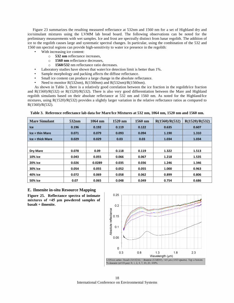
E. Ilmenite in-situ Resource Mapping
Figure 25. Reflectance spectra of intimate
mixtures of <45 μm powdered samples of
basalt + ilmenite.
International Conference on Environmental Systems
19
The University of Winnipeg has studied the spectral characteristics of suites of basalt + ilmenite, one of which
is shown below (Figure 25). These mineral mixtures are being used to assess the wavelength coverage and spectral
resolution necessary to permit detection of ilmenite and constraints to be placed on ilmenite abundances.
The extensive study of the spectroscopic properties of lunar minerals [Cloutis et al. 2008]15
showed that
ilmenite is spectrally distinct from other lunar minerals, provided that both ultraviolet and visible wavelengths are
used for such determinations. Ilmenite exhibits a characteristic blue shift in its spectral reflectance relative to the
other relevant lunar minerals, as shown in Figure 25, with an enhanced reflectance in the UV near 290nm.
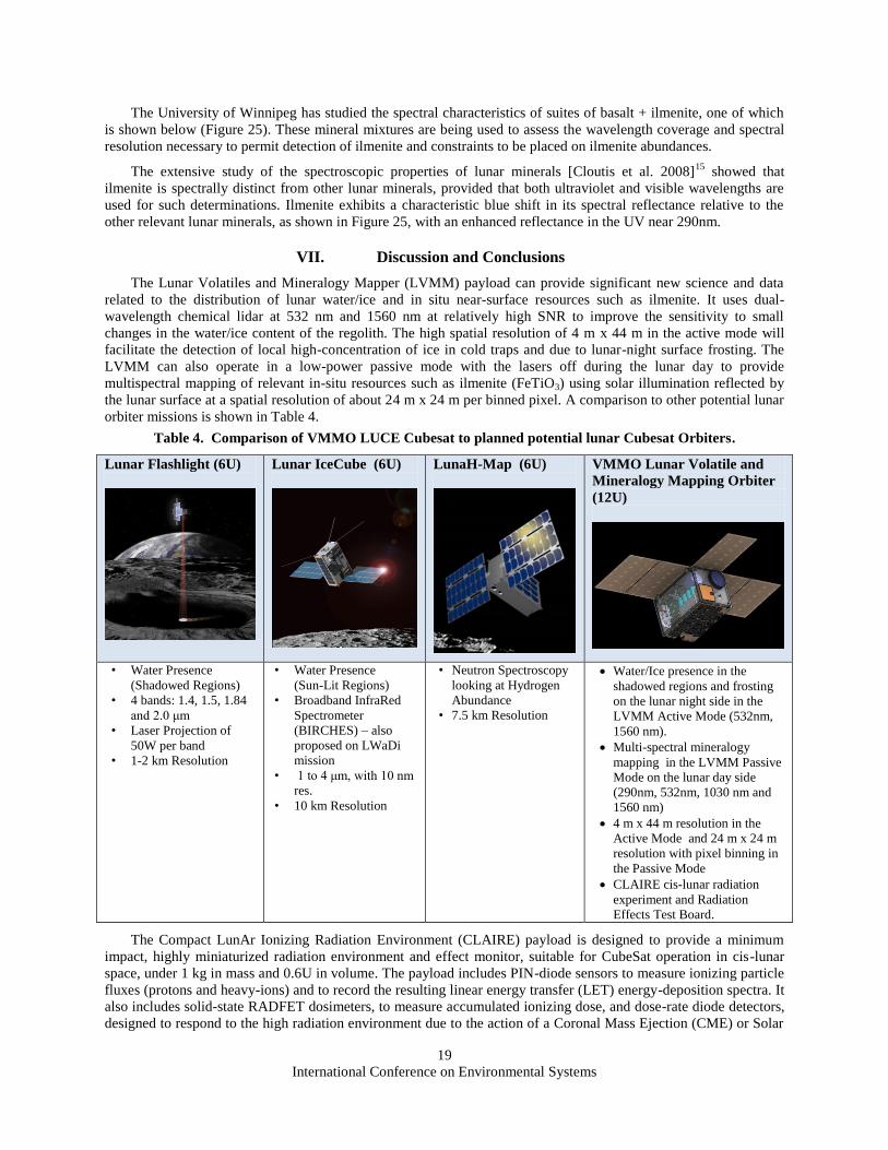
VII. Discussion and Conclusions
The Lunar Volatiles and Mineralogy Mapper (LVMM) payload can provide significant new science and data
related to the distribution of lunar water/ice and in situ near-surface resources such as ilmenite. It uses dual-
wavelength chemical lidar at 532 nm and 1560 nm at relatively high SNR to improve the sensitivity to small
changes in the water/ice content of the regolith. The high spatial resolution of 4 m x 44 m in the active mode will
facilitate the detection of local high-concentration of ice in cold traps and due to lunar-night surface frosting. The
LVMM can also operate in a low-power passive mode with the lasers off during the lunar day to provide
multispectral mapping of relevant in-situ resources such as ilmenite (FeTiO3) using solar illumination reflected by
the lunar surface at a spatial resolution of about 24 m x 24 m per binned pixel. A comparison to other potential lunar
orbiter missions is shown in Table 4.
Table 4. Comparison of VMMO LUCE Cubesat to planned potential lunar Cubesat Orbiters.
Lunar Flashlight (6U)
Lunar IceCube (6U)
LunaH-Map (6U)
VMMO Lunar Volatile and
Mineralogy Mapping Orbiter
(12U)
• Water Presence
(Shadowed Regions)
• 4 bands: 1.4, 1.5, 1.84
and 2.0 μm
• Laser Projection of
50W per band
• 1-2 km Resolution
• Water Presence
(Sun-Lit Regions)
• Broadband InfraRed
Spectrometer
(BIRCHES) – also
proposed on LWaDi
mission
• 1 to 4 μm, with 10 nm
res.
• 10 km Resolution
• Neutron Spectroscopy
looking at Hydrogen
Abundance
• 7.5 km Resolution
Water/Ice presence in the
shadowed regions and frosting
on the lunar night side in the
LVMM Active Mode (532nm,
1560 nm).
Multi-spectral mineralogy
mapping in the LVMM Passive
Mode on the lunar day side
(290nm, 532nm, 1030 nm and
1560 nm)
4 m x 44 m resolution in the
Active Mode and 24 m x 24 m
resolution with pixel binning in
the Passive Mode
CLAIRE cis-lunar radiation
experiment and Radiation
Effects Test Board.
The Compact LunAr Ionizing Radiation Environment (CLAIRE) payload is designed to provide a minimum
impact, highly miniaturized radiation environment and effect monitor, suitable for CubeSat operation in cis-lunar
space, under 1 kg in mass and 0.6U in volume. The payload includes PIN-diode sensors to measure ionizing particle
fluxes (protons and heavy-ions) and to record the resulting linear energy transfer (LET) energy-deposition spectra. It
also includes solid-state RADFET dosimeters, to measure accumulated ionizing dose, and dose-rate diode detectors,
designed to respond to the high radiation environment due to the action of a Coronal Mass Ejection (CME) or Solar
International Conference on Environmental Systems
20
Particle Event (SPE). The CLAIRE payload draws on heritage from the MuREM and RM payloads, flown on the
UK’s TDS-1 spacecraft launched in 2014. It also makes use of the more recent development of the Surrey Space
Centre’s ZENITH payload, designed to monitor the radiation environment in Earth’s upper atmosphere.
The VMMO LUCE Cubesat will also develop and flight qualify in a relevant lunar orbit environment an
altitude and orbit control system (AOCS) for semi-autonomous beyond-LEO spacecraft operations. VMMO will
also validate a hybrid electric/cold-gas propulsion subsystem to enable acquisition of the low-eccentricity frozen
operating lunar orbit and de-spinning of the on-board reaction wheels. Claire will allow the correlation of the
VMMO performance with the cis-lunar radiation environment to advance the TRL for beyond-LEO Cubesats.
The CLAIRE Radiation Effects Test Board will assess the performance of a range of relevant commercial-off-
the-shelf (COTS) electronic devices operating in a real lunar radiation environment by monitoring for single-event-
effects (SEE) and power consumption changes due to total-dose damage. This will allow direct correlations to be
drawn between effects on the selected electronics test bed and the real measured environment.
Acknowledgments
The authors would like to acknowledge the European Space Agency for enabling this mission concept study through
the ESA LUCE Cubesat SysNova Challenge program.
Special thanks to Roger Walker and Johan Vennekens from ESA for their constructive criticisms and questions.
References 1.
https://www.nasa.gov/mission_pages/LCROSS/main/prelim_water_results.html (accessed Nov. , 2017). 2. Taylor, L.A., McKay D.S., Carrier W.D., Carter J.L. and Wieblen P. ‟The nature of lunar soil: Considerations for
simulants,” Space Resources Roundtable VI, abstract # 6024, 2004. 3.Pieters, C. M., Goswami, J. N., Clark, R. N., Annadurai, M., Boardman, J., Buratti, B., and Hibbitts, C., "Character and
spatial distribution of OH/H2O on the surface of the Moon seen by M3 on Chandrayaan-1," Science, 326 (5952), pp. 568-572,
2009. 4.Wilson et al., Lunar Proton Albedo Anomalies: Soil, Surveyors, and Statistics [#2229], LPSC, March, 2015
(Poster), Referenced in Schwadron, N. A., Spence, H. E., Wilson, J. K., Jordan, A. P., Winslow, R., Joyce, C., .and Stubbs, T. J.,.
"LRO/CRaTER Discoveries of the Lunar Radiation Environment and Lunar Regolith Alteration by Radiation,". in Lunar and
Planetary Science Conference, Vol. 46, pp. 2395, 2015. 5. Feldman, W. C., S. Maurice, A. B. Binder, B. L. Barraclough, R. C. Elphic, and D. J. Lawrence. "Fluxes of fast and
epithermal neutrons from Lunar Prospector: Evidence for water ice at the lunar poles."Science 281, no. 5382, pp. 1496-1500,
1998. 6 Haddad, E., Kruzelecky, R.V., Mena, M., Tagzira, K., Rizzi, F., McKenzie, I., Karafolas, N., Hannateau, F., "Optical
Fiber Sensor Systems on Proba-2 after 7 years," ICSO, 2016. 7.Latendresse, V., Kruzelecky, R.V., Murzionak, P., Lavoie, J., Wallach, E., Nakhaei, A., Sinclai, I., and. Jamroz, W.,
"LIRA LIBS for Stand-off Planetary and Asteroid Resource Prospecting," ASCE Earth and Space Conference, Orlando, FL,
2016. 8.U.S. Geological Survey, URL: https://pubs.usgs.gov/pp/p1386a/gallery2-fig77.html.(accessed Nov., 2017). 9.Hiroi, T., Isaacson, P.J., Klima, R.L., , Pieters, C.M.,, Sarbadhikari, A.B., Liu, Y., and Taylor, L.A., "Reproducing
Visible and Near-Infrared Reflectance Spectra of Lunar Rocks directly from their End-Member Spectra: Importance of Ilmenite
in Estimating the Lunar Surface Composition," 40th Lunar and Planetary Science Conference, paper 1723, 2009. 10 Pitcher, C., Kömle, N Leibniz, O., Morales-Calderon, O., Gao, Y., and Richter, L., "Investigation of the properties of icy
lunar polar regolith simulants," Advances in Space Research, Vol. 57, Issue 5, pp. 1197–1208, doi:10.1016/j.asr.2015.12.030,
2016. 11.Pitcher, C. and Gao, Y., “Physical Properties of Icy Materials,” in Outer Solar System: Prospective Energy and Material
Resources, Springer-Verlag, ISBN: 978-3-319-73844-4, doi:10.1007/978-3-319-73845-1, 2018. 12 https://www.photometrics.com/prime-scmos-camera-family.php. 13.www.sensorsinc.com/company/utc-aerospace. 14.Underwood, C., Taylor, B., Dyer, A., Hands, A., Ryden, K., Avison, W., & Bamber, D., "Development of miniaturized
radiation environment monitors for commercial spaceflight: Flight results from the MuREM/RM payloads," in 16th European
Conference on Radiation and Its Effects on Components and Systems (RADECS), pp. 1-8, IEEE, 2016. 15 Cloutis, E.A., "Spectroscopy-based analysis of astromaterials," Planetary Science Research Symposium; Edmonton, AB,
Canada, 2008.