Embed Size (px)
Citation preview

OP
ER
AT
IN
G
IN
ST
RU
CT
IO
NS
V M S 1 0 0V o l u m e M e a s u r e m e n t S y s t e m

Software version Operating Instructions
VMS 100 Volume Measurement System
2 © SICK AG · Division Auto Ident · Germany · All rights reserved 8 009 406/14-02-2002
Software versions described
Software/Tool Function Version
gnu960_VMS100_2-21 Evaluation Software (Firmware) V2.21 20-09-2001
VMS100_setup Commissioning Software V2.11 20-09-2001
Windows ’95TM; Windows ’98TM and Windows NTTM are registered trade marks or trade marks of theMicrosoft Corporation in the USA and other countries.

Operating Instructions Contents
VMS 100
8 009 406/14-02-2002 © SICK AG · Division Auto Ident · Germany · All rights reserved 3
Contents
1 About this document .......................................................................................................... 91.1 Function ................................ ................................ ................................ ................................ .. 91.2 Target group................................ ................................ ................................ ............................ 9
1.2.1 Mounting, electrical installation, device replacement................................ ..................... 91.2.2 Commissioning, maintenance................................ ................................ ....................... 91.2.3 Operation................................ ................................ ................................ ...................... 9
1.3 Depth of information ................................ ................................ ................................ ................ 91.4 Symbology used................................ ................................ ................................ .................... 10
2 For your safet .................................................................................................................. 112.1 Authorised personnel................................ ................................ ................................ ............. 11
2.1.1 Mounting and maintenance................................ ................................ ......................... 112.1.2 Electrical installation and replacement of devices ................................ ....................... 112.1.3 Commissioning, operation and parameter-setting................................ ....................... 11
2.2 Proper use................................ ................................ ................................ ............................. 112.3 General safety information and protective measures ................................ ............................. 122.4 Quick stop and quick start ................................ ................................ ................................ ..... 13
2.4.1 Switching off the VMS 100................................ ................................ .......................... 132.4.2 Switching on the VMS 100 ................................ ................................ .......................... 13
2.5 Environmental friendliness................................ ................................ ................................ ..... 132.5.1 Energy requirement ................................ ................................ ................................ .... 132.5.2 Disposal after final decommissioning................................ ................................ .......... 13
3 Product description.......................................................................................................... 143.1 System components ................................ ................................ ................................ .............. 14
3.1.1 Equipment supplied ................................ ................................ ................................ .... 143.1.2 System requirements................................ ................................ ................................ .. 143.1.3 System view ................................ ................................ ................................ ............... 15
3.2 The operating principle of the VMS 100................................ ................................ ................. 163.3 Indicators and operating elements ................................ ................................ ......................... 19
3.3.1 Operating elements ................................ ................................ ................................ .... 193.3.2 Functions of the LED indicators ................................ ................................ .................. 19
3.4 Requirements and measurement accuracy................................ ................................ ............ 203.5 Overview of commissioning ................................ ................................ ................................ ... 22
4 Mounting............................................................................................................................ 234.1 Overview of the steps involved in mounting ................................ ................................ ........... 234.2 Preparing for mounting ................................ ................................ ................................ .......... 23
4.2.1 Prepare the components for mounting................................ ................................ ........ 234.2.2 Prepare the accessories ................................ ................................ ............................. 234.2.3 Prepare mounting aids................................ ................................ ................................ 234.2.4 Selecting the mounting location ................................ ................................ .................. 234.2.5 Mounting accessories ................................ ................................ ................................ . 24
4.3 Mounting the LMS 200................................ ................................ ................................ ........... 244.4 Mounting the VMC 100 ................................ ................................ ................................ .......... 254.5 Adjusting the LMS 200................................ ................................ ................................ ........... 25

Contents Operating Instructions
VMS 100 Volume Measurement System
4 © SICK AG · Division Auto Ident · Germany · All rights reserved 8 009 406/14-02-2002
4.6 Dismantling the system ................................ ................................ ................................ ..........26
5 Electrical installation ........................................................................................................ 275.1 Overview of the installation steps ................................ ................................ ........................... 275.2 Electrical connections and cables................................ ................................ ........................... 275.3 Pin configuration for the connections................................ ................................ ...................... 28
5.3.1 LMS 200 connections................................ ................................ ................................ ..285.3.2 VMC 100 connections ................................ ................................ ................................ .29
5.4 Carrying out the electrical installation ................................ ................................ ..................... 32
6 Commissioning and parameter-setting........................................................................... 336.1 Starting the VM 100 Commissioning Software ................................ ................................ .....336.2 Setting parameters................................ ................................ ................................ .................33
6.2.1 Setting measurement area parameters ................................ ................................ .......346.2.2 Setting detection zone parameters ................................ ................................ ..............356.2.3 Setting velocity parameters ................................ ................................ ......................... 366.2.4 Setting process control parameters ................................ ................................ .............366.2.5 Setting optional device parameters ................................ ................................ .............376.2.6 Data transfer ................................ ................................ ................................ ...............37
6.3 Output of measurement data on the screen ................................ ................................ ...........376.4 Completion and test measurements ................................ ................................ ....................... 38
7 Maintenance ...................................................................................................................... 397.1 Maintenance during operation................................ ................................ ................................ 397.2 Maintenance ................................ ................................ ................................ .......................... 407.3 Disposal ................................ ................................ ................................ ................................ .40
8 Troubleshooting................................................................................................................ 418.1 Overview of possible faults and problems ................................ ................................ ..............41
8.1.1 Mounting error................................ ................................ ................................ .............418.1.2 Error in the electrical installation................................ ................................ .................. 418.1.3 Parameterisation error................................ ................................ ................................ .418.1.4 Operating difficulties................................ ................................ ................................ ....41
8.2 Monitoring signs of faults and problems ................................ ................................ .................418.3 Identifying faults and remedying them................................ ................................ .................... 418.4 SICK Support ................................ ................................ ................................ ......................... 43
9 Technical data ................................................................................................................... 449.1 Data sheet for the VMS 100 Volume Measurement System................................ ................... 449.2 Dimensional drawings ................................ ................................ ................................ ............45
9.2.1 LMS 200-30106 Laser Measurement System dimensional drawing ............................ 459.2.2 VMC 100-0000 evaluation unit dimensional drawing ................................ ................... 469.2.3 View of Mounting Set for LMS 200-30106 ................................ ................................ ...479.2.4 View of VMC 100-0100 ................................ ................................ ............................... 48
10 Appendix............................................................................................................................ 4910.1 Overview of the Appendix................................ ................................ ................................ .......4910.2 Telegram structure ................................ ................................ ................................ .................49
10.2.1 Telegram format................................ ................................ ................................ ..........4910.2.2 VMC 100 status................................ ................................ ................................ ...........50

Operating Instructions Contents
VMS 100
8 009 406/14-02-2002 © SICK AG · Division Auto Ident · Germany · All rights reserved 5
10.2.3 LMS 200 device status ................................ ................................ ............................... 5010.2.4 Replacing a system or components ................................ ................................ ............ 51
10.3 Available accessories (order details) ................................ ................................ ..................... 5210.3.1 The complete VMS 100 systems ................................ ................................ ................ 5210.3.2 Accessories ................................ ................................ ................................ ................ 5210.3.3 View of the accessories ................................ ................................ .............................. 53
10.4 Supplementary documentation ................................ ................................ .............................. 5310.5 The EU Declaration of Conformity ................................ ................................ ......................... 54
10.5.1 The LMS 200 EU Declaration of Conformity ................................ ............................... 5410.5.2 The VMC 100 EU Declaration of Conformity................................ ............................... 56
10.6 Commissioning log ................................ ................................ ................................ ................ 5810.7 Inde ................................ ................................ ................................ ................................ ..... 59

Tables and figures Operating Instructions
VMS 100 Volume Measurement System
6 © SICK AG · Division Auto Ident · Germany · All rights reserved 8 009 406/14-02-2002
Abbreviations used
HD High density
LED Light emitting diode
LMI Laser Measurement Interface
LMS Laser Measurement System
VMS Volume Measurement System
VMC Volume Measurement Controller
Tables
Table 3-1: VMC 100 LED indicators........................................................................................................................... 19
Table 3-2: LMS 200 LED indicators. .......................................................................................................................... 19
Table 3-3: Minimum and maximum dimensions of rectangular objects..................................................................... 20
Table 3-4: Object gaps typically required................................................................................................................... 20
Table 3-5: Typical accuracy for an object with dimensions > 200 x 200 x 200 mm³ (L x W x H). ............................. 20
Table 3-6: Levels of accuracy for an object with dimensions > 200 x 200 x 200 mm³ (L x W x H). .......................... 21
Table 5-1: LMS 200: pin configuration on the 9-pin D-sub device plug..................................................................... 28
Table 5-2: LMS 200: pin configuration on the 9-pin D-sub device socket. ................................................................ 28
Table 5-3: VMC 100: Configuration of the plug-in terminal strips for VMS 100 functions. ........................................ 30
Table 5-4: VMC 100: Pin configuration for the 9-pin D-sub device socket ("COM" connection). .............................. 31
Table 5-5: LIM 200: "COM" data interface communication parameter values........................................................... 31
Table 5-6: VMC 100: pin configuration for 15-pin D-sub HD device socket ("BUS" connection). ............................. 32
Table 6-1: Setting parameters for maximum detectable object lengths and possible speed ranges. ....................... 36
Table 7-1: LMS 200: LED error indicators on contamination of the front window...................................................... 39
Table 7-2: VMC 100: LED error indicators on contamination of the LMS front window. ........................................... 39
Table 8-1: Troubleshooting table. .............................................................................................................................. 42
Table 9-1: Technical specifications for the VMS 100................................................................................................. 44
Table 10-1: Telegram format at the COM data interface (VMC 100)......................................................................... 49
Table 10-2: Structure of external telegrams............................................................................................................... 50
Table 10-3: Output telegram: meaning of the VMC 100 status. ................................................................................ 50
Table 10-4: Output telegram: meaning of the LMS 200 device status....................................................................... 50
Table 10-5: Order details: the complete VMS 100 system. ....................................................................................... 52
Table 10-6: Order details: optional accessories for operation. .................................................................................. 52
Table 10-7: Order details: optional accessories for commissioning. ......................................................................... 52
Table 10-8: Supplementary documentation. .............................................................................................................. 53

Operating Instructions Tables and figures
VMS 100
8 009 406/14-02-2002 © SICK AG · Division Auto Ident · Germany · All rights reserved 7
Illustrations
Fig. 2-1: Laser warning plates attached to the LMS 200. .......................................................................................... 12
Fig. 3-1: Structure of the VMS 100-0000 with the VMC 100-0000 evaluation unit. ................................................... 15
Fig. 3-2: View inside the VMC 100-0100 evaluation unit. .......................................................................................... 16
Fig. 3-3: The LMS 200-30106. ................................................................................................................................... 16
Fig. 3-4: The LMI 200................................................................................................................................................. 17
Fig. 3-5. Sketch of the VMS 100 with its frame above the transport system............................................................. 17
Fig. 3-6: Schematic diagram of VMS 100 components and peripheral devices. ....................................................... 18
Fig. 3-7: Schematic diagram showing LMS 200 installation above a transport system. ........................................... 21
Fig. 4-1: Dimensional drawing for Mounting Set with LMS 200 ................................................................................. 24
Fig. 4-2: Mounting of the LMS 200 from above the transport system........................................................................ 24
Fig. 4-3: Definition of the LMS 200 angles �� � ��� �� ............................................................................................... 25
Fig. 4-4: View from above the LMS 200 with plumbline and measurement line........................................................ 26
Fig. 5-1: VMC 100: position of the terminal strips and D-sub plug connections on the front panel........................... 29
Fig. 6-2: Sketch of the measurement area and detection zone with the height of the detection line. ....................... 35
Fig. 6-3: Display of measure ent data, an example after a restart........................................................................... 38
Fig. 9-1: Dimensions of the LMS 200-30106 Laser Measurement Syste ............................................................... 45
Fig. 9-2: Dimensions of the VMC 100-0000 evaluation unit ...................................................................................... 46
Fig. 9-3: Structure of Mounting Set no. 2 020 925 ..................................................................................................... 47
Fig. 9-4: Dimensions of the VMC 100-0100 evaluation unit. ..................................................................................... 48
Fig. 10-1: Structure and electrical connection of the heating plate no. 2 019 522..................................................... 53
Fig. 10-2: The EU Declaration of Conformity for the LMS 200, Page 3 (reduced in size)......................................... 54
Fig. 10-3: The EU Declaration of Conformity for the LMS 200, Page 2 (reduced in size). ........................................ 55
Fig. 10-4: The EU Declaration of Conformity for the VMC 100, Page 3 (reduced in size). ....................................... 56
Fig. 10-5: The EU Declaration of Conformity for the VMC 100, Page 2 (reduced in size). ....................................... 57

Tables and figures Operating Instructions
VMS 100 Volume Measurement System
8 © SICK AG · Division Auto Ident · Germany · All rights reserved 8 009 406/14-02-2002

Operating Instructions About this document Chapter 1
VMS 100
8 009 406/14-02-2002 © SICK AG · Division Auto Ident · Germany · All rights reserved 9
1 About this document
1.1 Function
This document provides instructions for commissioning, operating and maintaining the SICK VMS 100Volume Measurement System.
The document contains information on:
• mounting and electrical installation,• commissioning,• operation and configuration (parameter-setting),• maintenance,• replacing system components.
The VMS 100 Volume Measurement System will simply be described as the VMS 100 in this document.
1.2 Target group
The target group of this document are persons carrying out the following activities:
1.2.1 Mounting, electrical installation, device replacement
Specialist personnel such as service technicians or factory electricians
1.2.2 Commissioning, maintenance
Specialist personnel such as technicians or engineers
1.2.3 Operation
Specialist personnel for operation and parameterisation of the transport system
1.3 Depth of information
This document contains all the information necessary for the mounting, electrical installation and commissio-ning of the VMS 100 with the basic operational settings. Step-by-step instructions are provided for all activi-ties.
Configuration (parameter-setting) of the VMS 100 for on-site application is carried out using the VMS 100Commissioning Software. Installation of the software and interaction with the user interface is described inChapter 6 Commissioning and parameter-setting.
The document provides information on the working principle and the technical data of the VMS 100 VolumeMeasurement System. Details on the LMS 200 Laser Measurement System (Type 30106) and the VMC 100evaluation unit (based on the SICK device LMI 200) can be found in the appropriate documentation, seeChapter 10.4 Supplementary documentation.
Further information on Volume Measurement Systems, Laser Measurement Systems and bar-code scannerscan be obtained from SICK AG, Division Auto Ident.

Chapter 1 About this document Operating Instructions
VMS 100 Volume Measurement System
10 © SICK AG · Division Auto Ident · Germany · All rights reserved 8 009 406/14-02-2002
1.4 Symbology used
Some information in this documentation is given particular emphasis to make it easier to find it quickly.
WARNING!Warnings prevent physical injury or serious damage to the VMS 100.
� Always read warnings attentively and follow instructions carefully.
Recommendation A recommendation helps you carry out an activity more efficiently.
Please note Such notes provide information on special features.
Font This style of writing signifies an input or term in the user interface of the VMS 100Commissioning Software.
Reference Italics are used to refer to more detailed information elsewhere.
� You must do something here. This symbol signifies an action comprising a single-stepinstruction. Instructions involving more than one step are signified by the use of succes-sive numbers.
ATTENTION

Ooperating Instructions For your safety Chapter 2
VMS 100
8 009 406/14-02-2002 © SICK AG · Division Auto Ident · Germany · All rights reserved 11
2 For your safety
2.1 Authorised personnel
Sufficiently qualified personnel must mount and operate the VMS 100 to ensure proper and safe function.
The following qualifications are required for the various activities:
2.1.1 Mounting and maintenance
• Practical technical training• Knowledge of current safety regulations for the workplace
2.1.2 Electrical installation and replacement of devices
• Practical training in electrical engineering• Knowledge of the current electrical engineering safety regulations• Knowledge on the operation and use of transport systems
2.1.3 Commissioning, operation and parameter-setting
• Knowledge of the mechanical and electrical engineering parameters of transport systems and the proper-ties of transport systems regarding their operation and use
• Basic knowledge of Windows NTTM/Windows 95• Basic knowledge of data transfer
2.2 Proper use
The VMS 100 Volume Measurement System measures rectangular objects on transport systems. The VMS100 determines the length, width and height of rectangular objects and transfers this information, via a datainterface, to a higher-ranking computer for further processing.
The measurement system is not a device for protecting persons as definded by current machinesafety standards.
The system consists of an LMS 200 Laser Measurement System of type 30106 (enclosure rating IP 65) and aVMC 100 Controller, also known as an evaluation unit (VMC 100-0000: enclosure rating IP 20, VMC 100-0100: enclosure rating IP 65). There is a switchable RS-232/RS-422 interface on the evaluation unit for dataoutput. Devices such as a bar-code scanner or weighing machine can be connected to an RS-485 interface.A shaft encoder and photoelectric switch can be connected to the VMC 100.
All warranty claims against SICK AG are forfeited in the case of any other use, or alterations being made todevices, even as part of their mounting or electrical installation.

Chapter 2 For your safety Operating Instructions
VMS 100 Volume Measurement System
12 © SICK AG · Division Auto Ident · Germany · All rights reserved 8 009 406/14-02-2002
2.3 General safety information and protective measures
� Read the general safety information attentively and follow it carefully during all activities with the VMS100. Similarly, pay attention to the warnings before instructions in the individual chapters of this docu-ment.
Danger of injury through electrical current
The VMC 100 (DC 24 V) can also be connected to the power supply network (AC 230 V50 Hz) via a power supply unit.
� Follow the current safety regulations when working with electrical equipment.
Laser radiation
The LMS 200 operates using a Class 1 infrared laser.
� Follow laser protection regulations according to DIN EN 60825-1 (latest version).
Laser warning plate
The laser warning plate and laser warning symbol (Fig. 2-1) are located on the right-hand side of the LMS 200Laser Measurement System, as seen from the front.
Fig. 2-1: Laser warning plates attached to the LMS 200.
Please note:
If the Laser Measurement System is installed within a machine/casing in such a way that the laserwarning plates are covered up, more warning plates (not supplied) must be attached to themachine/casing next to the laser beam exit window!
ATTEN ION
ATTENTION

Ooperating Instructions For your safety Chapter 2
VMS 100
8 009 406/14-02-2002 © SICK AG · Division Auto Ident · Germany · All rights reserved 13
2.4 Quick stop and quick start
2.4.1 Switching off the VMS 100
� Switch off the VMC 100's power supply.The VMS 100 retains permanently stored parameters in its internal memory. Measurement data are lost.
2.4.2 Switching on the VMS 100
� Switch on the VMC 100's power supply.The VMS 100 restarts operation with the parameters that were most recently saved.
2.5 Environmental friendliness
The VMS 100 is constructed in such a way that it adversely affects the environment as little as possible.
2.5.1 Energy requirement
The VMS 100, with the LMS 200 and VMC 100, has a maximum consumption of approx. 60 W.
2.5.2 Disposal after final decommissioning
Dispose of unusable or irreparable devices in an environmentally friendly manner according to the particularwaste disposal regulations valid in the country of use. The VMS is constructed to allow separation into recy-clable secondary raw materials and special waste (electronic scrap). See Chapter 7.3 Disposal.
SICK AG does not currently take back any unusable or irreparable devices.

Chapter 3 Product description Operating Instructions
VMS 100 Volume Measurement System
14 © SICK AG · Division Auto Ident · Germany · All rights reserved 8 009 406/14-02-2002
3 Product description
3.1 System components
3.1.1 Equipment supplied
The VMS 100 is supplied with:
• one LMS 200-30106 Laser Measurement System,• one Mounting Set for adjusting the LMS 200-30106, two-axis, fine adjustment,• one VMC 100 Volume Measurement Controller with VMS 100 Evaluation Software installed.
VMC 100-0000 with Mounting Set for wall mounting.VMC 100-0100 with switching cabinet incl. power supply unit,
• one Set for the electrical connection of the LMS 200-30106 to the VMC 100,• one diskette with VMS 100 Commissioning Software for a PC under Windows NTTM/Windows 95,• one set of VMS 100 Operating Instructions
Chapter 10.3 Available accessories (order details) provides an overview of the accessories for operation,installation and electrical connection, as well as supplementary documentation.
3.1.2 System requirements
The following are required for commissioning and operating the VMS 100:
• Installation of the LMS 200 typically requires 1300 mm space above the tallest object.• VMC 100-0000 operating voltage DC 24 V ± 15% acc. to IEC 742 (functional low voltage), consumption
ca. 60 W. VMC 100-0100 operating voltage AC 230 V -15%/+10% 50 Hz.• PC with Windows NTTM/Windows 95 operating system and RS-232 interface.• RS-232 data connection cable with two 9-pin D-sub sockets, e.g. order no. 2 016 401.• RS-232 or RS-422 data interface on measurement result destination computer.• Connection module for bus systems available on request.• Transport system: constant transport speed or shaft encoder (resolution min. 1 incr./mm, see Chapter
10.3 Available accessories) and a flat transport surface.
Optional:
• A switch or host telegram to start the measurement process if "limited measurement readiness" is se-lected as the operating mode.
• An auxiliary device (e.g. bar-code scanner) with data output via telegram for joint output of separatelydetermined information.

Operating Instructions Product description Chapter 3
VMS 100
8 009 406/14-02-2002 © SICK AG · Division Auto Ident · Germany · All rights reserved 15
3.1.3 System view
LMS 200 and VMC 100-0000
Fig. 3-1: Structure of the system with the VMC 100-0000 evaluation unit.
Legend:� Laser Measurement
System� Mounting Set� Connection module� LED indicators
�
�
�
�
�
�
LMS 200
VMC 100-0000
��
� Read windo� Electrical connections� "COM" connection (data output)� Connection for optional devices LED indicators

Chapter 3 Product description Operating Instructions
VMS 100 Volume Measurement System
16 © SICK AG · Division Auto Ident · Germany · All rights reserved 8 009 406/14-02-2002
VCM 100-0100
Fig. 3-2: View inside the VMC 100-0100 evaluation unit.
The VMC 100-0000 is integrated inside a switching cabinet (not yet completely wired up in the picture).
3.2 The operating principle of the VMS 100
The VMS 100 Volume Measurement System determines the length, width and height of rectangular objects inany alignment on transport systems without contact and in real time. An optional input and output of sepa-rately determined information (e.g. bar-codes) can take place.
The operating principle of the LMS 200-30106
The Laser Measurement System LMS 200-30106 scans a two-dimensional measurement area without con-tact. The LMS requires no reflectors or position marks. No illumination of objects is necessary as it is an ac-tive system with an infrared laser.
Fig. 3-3: The LMS 200-30106.
Main switch
Connection for customer’sPower supply
VMC 100-0000

Operating Instructions Product description Chapter 3
VMS 100
8 009 406/14-02-2002 © SICK AG · Division Auto Ident · Germany · All rights reserved 17
The LMS operates according to the time-of-flight principle. The distance from the object to the system is de-termined from the time between the transmission of a light pulse and the reception of the light reflected by theobject, as measured by the LMS.
The operating principle of the VMC 100
The VMC 100 Laser Measurement Interface is based on the LMI 200. The LMI 200 is a multifunctionalevaluation unit specially developed for processing LMS data. The LMI 200 can process and transmit, viadigital and analogue interfaces, the process data obtained for various measurement commands. The MST200 Measurement Software Tool is available for the development of customer-specific evaluation software.
Fig. 3-4: The LMI 200.
According to its configuration, the LMI 200 processes data supplied by the LMS 200 Laser MeasurementSystem together with other information. These data are processed in real time and given out at the interfacesas measurement results.
The operating principle of the VMS 100
An LMS 200 Laser Measurement System is installed above the transport system. It scans the surface of thetransport system and the transported objects about every 13.3 ms. The distance data obtained by the LMS200 are transferred to the VMC 100 in real time. The speed of the transported objects is set as a constant orcan be provided using an optional shaft encoder.
Fig. 3-5. Sketch of the VMS 100 with its frame above the transport system.
Object
LMS

Chapter 3 Product description Operating Instructions
VMS 100 Volume Measurement System
18 © SICK AG · Division Auto Ident · Germany · All rights reserved 8 009 406/14-02-2002
The three-dimensional information on the rectangular object is available after the distance data have beendetermined and the speed calculated in. The VMS program calculates the length, width and height of therectangular object from the measurement data. Output of the data takes place at the VMC 100's selectableRS-232/RS-422 interface.
VMS 100 layout
The measurement data is made available at an RS-232/RS-422 interface. Connection to a data transfer sys-tem can take place via gateways or interface converters.A shaft encoder can be connected to the VMC 100. The VMC 100 can receive results from auxiliary devices(e.g. bar-code measurements) via the RS-485 interface and give them out in real time together with the di-mensional data at the RS-232/RS-422 interface of the VMC 100.
Please note:Customers require their own Windows NT/Windows 95 PC with RS-232 interface and a data cable (e.g.2016401) for commissioning and parameter-setting.
The following schematic diagram shows the components of the VMS 100.
Fig. 3-6: Schematic diagram of VMS 100 components and peripheral devices.
E.g. bar-code reader
E.g. scales
VMS 100
optional
Shaft encoder
Host, converterfor bus system, etc.
PC + softwar
Commissionin
LMS 20 VMC 100 + software
RS-485
RS-232/-422
Switch
RS-232

Operating Instructions Product description Chapter 3
VMS 100
8 009 406/14-02-2002 © SICK AG · Division Auto Ident · Germany · All rights reserved 19
3.3 Indicators and operating elements
3.3.1 Operating elements
Parameterisation of the VMS 100 takes place via the supplied VMS 100 Commissioning Software, installedon the PC by the customer. The VMS 100 can be operated with permanent or limited measurement readi-ness:
• With permanent measurement readiness objects are automatically detected and the data recorded. Theobject data is calculated and given out after the end of the object has been reached.- Automatic Mode
• With limited measurement readiness the next object is only automatically detected and the data recordedafter activation. The object data is calculated and given out after the end of the object has been reached;the VMS 100 is then only ready for renewed measurement after reactivation. Activation can be carried outby:- a digital switch (falling flank),- a host telegram (renewed host request only after object measurement completed).
3.3.2 Functions of the LED indicators
Two LED indicators on the VMC 100 provide optical information on the operating state and errors. The LEDindicators are located on the front panel.
LED Indicator VMC 100 state
POWER green switched on (DC 24V supplied)
off switched off (no power supply)
MODE green Measurement Mode active
off Setup Mode
10% green blinking Service Mode
90% green blinking Measurement Mode is being activated
red Software Download Mode (VMC 100 busy)
green/red blinking Warning (e.g. front window contamination entered in error log), Measurement Mode is stillacitve1)
red blinking VMC 100 error (error entered in error log)1)
1) Run VMC 100 Diagnostics with User Software
Table 3-1: VMC 100 LED indicators.
Three LED indicators on the LMS 200 provide optical information on the operating state and errors.
LED Normal op-eration
Initialisation Contaminationwarning
Contaminationerror
Error Fatal error
Green 100% on off off off off
Yellow (1 Hz) off 100% on 50% on / 50% off 90% on / 10% off 10% on / 90% off 50% on / 50% off
Red off 100% on on on on
Table 3-2: LMS 200 LED indicators.

Chapter 3 Product description Operating Instructions
VMS 100 Volume Measurement System
20 © SICK AG · Division Auto Ident · Germany · All rights reserved 8 009 406/14-02-2002
3.4 Requirements and measurement accurac
Object requirements
The VMS 100 is designed for determining the volumes of rectangular objects. Rectangular objects havestraight sides with no curves or projections. The minimum and maximum object dimensions are summarisedin the following table:
Object dimension Minimum value Maximum value
Length along direction of transport 200 mm 1500 mm to 7500 mm
At right angles to direction of transport 200 mm 1500 mm
Height on the transport system 100 mm 1500 mm
Table 3-3: Minimum and maximum dimensions of rectangular objects.
Please note:The maximum value for the dimension along the direction of transport is 1500 mm as standard. How themaximum value can be varied is described in Table 6-1 in 6.2 Setting para eters.
The transport speed must be at least 0.1 m/s and at most 2 m/s. The time periods between objects must typi-cally be: at least 1/10 of the maximum object dimension along the direction of transport. See following table.
Object dimension along the direction of transport Gaps required between objects
< 1000 mm 100 mm
< 1500 mm 150 mm
Table 3-4: Object gaps typically required.
VMS 100 measurement accurac
Typical levels of accuracy are provided in Table 3-5.
Speed Typical accuracy
Speed < 1 m/s ± 15 mm in length, width and height
1 m/s ≤ speed ≤ 2 m/s ± 25 mm in length± 20 mm in width and height
Table 3-5: Typical accuracy for an object with dimensions > 200 x 200 x 200 mm³ (L x W x H).
The following accuracies apply at room temperature, with an object reflectivity of 10% to 1000% and for rec-ommended device structures corresponding to SICK documentation. Restricted ranges for object reflectivityand object dimensions provide higher levels of accuracy. Highly reflective surfaces and other effects canlower accuracy.

Operating Instructions Product description Chapter 3
VMS 100
8 009 406/14-02-2002 © SICK AG · Division Auto Ident · Germany · All rights reserved 21
Speed Accuracy
Speed < 1 m/s ± 30 mm in length, width and height
1 m/s ≤ speed ≤ 2 m/s ± 50 mm in length± 35 mm in width± 30 mm in height
Table 3-6: Levels of accuracy for an object with dimensions > 200 x 200 x 200 mm³ (L x W x H).
Transport system requirements
The typical space requirement for installation of the LMS is about 1300 mm above the tallest object. The dis-tance between the LMS and the upper surface of the tallest object must be at least about 700 mm, while adistance of about 1000 mm is recommended. Central mounting above the middle of the transport system isrecommended, see Fig.3-2. If the objects are fed in at one of the transport system's sides mounting can becarried out asymmetrically above the transport system.
Fig. 3-7: Schematic diagram showing LMS 200 installation above a transport system.
Objects can be moved using any transport system with a flat transporting surface.
Rotation, vibration, rolling motion and slippage of objects on the transport system, or uneven transport sur-faces, can reduce accuracy and have an adverse effect on data capture by the VMS. Curves, induction lines,start-stop sections, rising/falling sections and gaps in the transport system should be a sufficient distancefrom the measurement area for high accuracy and proper data capture.
The LMS 200 must have a clear view of the transport system.
The transport system must either have a constant transport velocity or a shaft encoder signal with a resolutionof at least 1 Incr./mm must be installed, see 10.3 Available accessories (order details).
maximum object height
min. approx. 700 mmrec. approx. 1000 mm
LMS above the middle of the transport system
LMS
Object

Chapter 3 Product description Operating Instructions
VMS 100 Volume Measurement System
22 © SICK AG · Division Auto Ident · Germany · All rights reserved 8 009 406/14-02-2002
LMS 200 mounting requirements
The LMS 200 must be mounted in such a way that it is:
• stable above the transport system (an LMS 200 unit weighs approx. 4.5 kg),• shock-free and vibration-free,• above the transport system.
Fig. 3-2 shows an LMS 200 installation above the transport system with typical distances.
Please note:The Mounting Set is easy to attach to an 8 mm item aluminium profile as it is designed for this profile. Thedimensional drawing in Fig. 4-1 is to be complied with for mounting using other equipment.
3.5 Overview of commissioning
1. Mount the LMS 200 (see 4 Mounting).2. Connect the LMS 200 to the VMC 100 with a data cable (see 5 Electrical installation).3. Connect the LMS 200 to the VMC 100 with a power supply cable (see 5 Electrical installation).4. Connect the power supply to the VMC 100 (see 5 Electrical installation).5. Adjust the LMS 200 (see 4 Mounting).6. Set VMS 100 parameters (see 6 Commissioning and parameter-setting).

Operating Instructions Mounting Chapter 4
VMS 100
8 009 406/14-02-2002 © SICK AG · Division Auto Ident · Germany · All rights reserved 23
4 Mounting
4.1 Overview of the steps involved in mounting
• If necessary: mount the frame in the desired area of the transport system• Attach the LMS Mounting Set to the frame or onto stable equipment• Attach the LMS 200 to the Mounting Set• Mount the VMC 100 evaluation unit
4.2 Preparing for mounting
4.2.1 Prepare the components for mounting
• The LMS 200 Laser Measurement System• The LMS 200 Mounting Set• The VMC 100 evaluation unit
4.2.2 Prepare the accessories
The following accessories will be needed for the Mounting Set and LMS 200-30106:
• Screws for attaching the Mounting Set to the frame or other equipment. The Mounting Set has 8xD6.6drilled holes, see Fig. 4-1.The LMS 200 weighs approx. 4.5 kg
• Four M8x12 screws with washers (supplied) for attaching the LMS 200 to the Mounting Set
4.2.3 Prepare mounting aids
• Plumbline• Spirit level• Measurement tape (up to 3000 mm) or folding metre-rule• Scanfinder• Pencil• Tools, M6 screws
4.2.4 Selecting the mounting location
The VMS 100 is supplied with a power supply cable and data transfer cable that are each 10 m long. Selectan appropriate mounting location for the LMS 200 and VMC 100.

Chapter 4 Mounting Operating Instructions
VMS 100 Volume Measurement System
24 © SICK AG · Division Auto Ident · Germany · All rights reserved 8 009 406/14-02-2002
4.2.5 Mounting accessories
A Mounting Set is supplied for mounting the LMS 200. It can be finely adjusted in two axes.
Fig. 4-1: Dimensional drawing for Mounting Set with LMS 200
Measurements in mm. Total LMS 200 weight is approx. 4.5 kg. The angles are based on Fig. 4-3.
4.3 Mounting the LMS 200
Fig. 4-2 shows the mounting of the LMS 200 from above the transport system. The angles α, β and γ are de-fined in Fig. 4-3.
Fig. 4-2: Mounting of the LMS 200 from above the transport system.
adjusting angle β
adjusting angle α
40
Object A
Object B
Direction of transport
Object CLMS 200
Connection
plug modules

Operating Instructions Mounting Chapter 4
VMS 100
8 009 406/14-02-2002 © SICK AG · Division Auto Ident · Germany · All rights reserved 25
Fig. 4-3: Definition of the LMS 200 angles �� � ��� ��
During preparation ensure that the LMS 200 and the Mounting Set can be mounted horizontally to the trans-���� ����� �� � γ = 0.
��� ��� ������ � ��� ��� �� �������� ���� ��� �������� ����
To align the LMS 200 above the middle of the transport area turn an M6 screw in the middle drilled hole at thebase of the LMS 200 and attach the plumbline to it with the lead touching the transport system. Determine themiddle of the transport area with transported objects on the transport system. Align the LMS 200 until the leadtouches the middle of the transport area.
4.4 Mounting the VMC 100
The VMC 100 must be freely accessible so that the electrical supply and data cables can be connected. TheVMC 100-0000 can be mounted on a standard mounting rail or the supplied bracket can be used. The VMC100-0100 is supplied as a version with a switching cabinet.
4.5 Adjusting the LMS 200
Please note:Electrical installation (5 Electrical installation) must be completed before adjustment.
Spatial alignment of the LMS 200
1. Turn an M6 screw in the middle drilled hole in the base of the LMS 200. Attach the plumbline in such away that it meets the end of the housing.
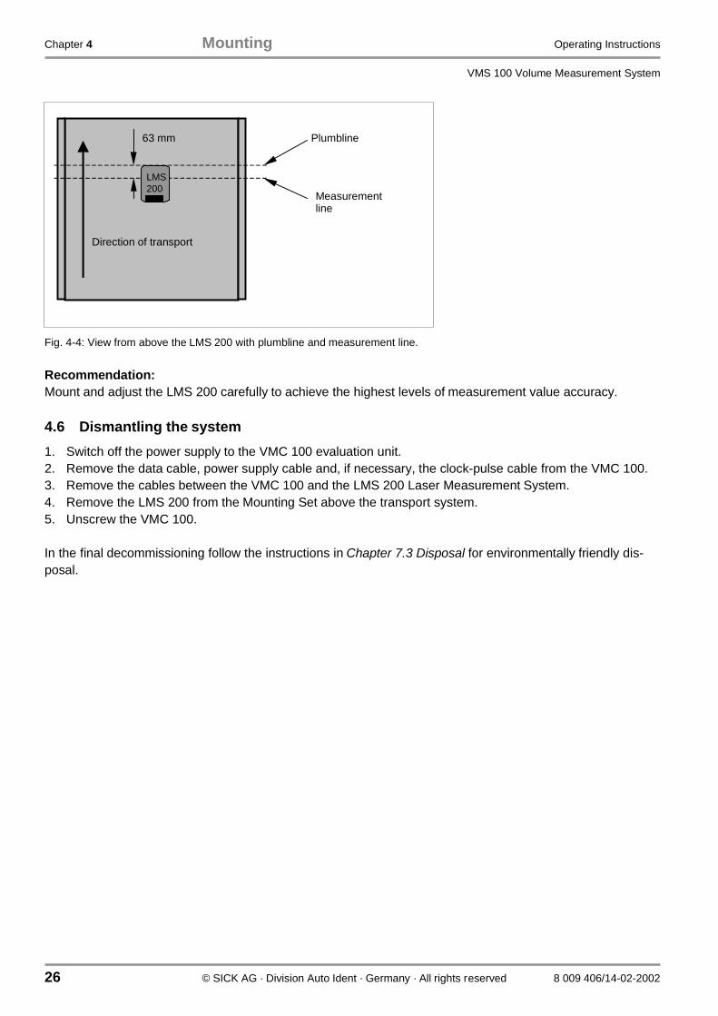
2. Turn the adjustment screw that is perpendicular to the direction of transport until the measurement line ofthe LMS 200 is located below the LMS 200 exactly 6.3 cm from where the plumbline meets the transportsystem in the direction of transport, see Fig. 4-4. Use the switched on Scanfinder to detect the measure-ment line (IR laser light).
3. Turn the adjustment screw that is in the direction of transport until the measurement line is on the trans-port system and perpendicular to the transport direction, see Fig. 4-4. For this purpose, use the switchedon Scanfinder to detect the measurement line (IR laser light) on the left or right side of the transport sys-tem.
α
Direction of transport
Side view
LMS
β
Direction of transport
View from above
LMS
γ
View in direction of transport
LMS
Chapter 4 Mounting Operating Instructions
VMS 100 Volume Measurement System
26 © SICK AG · Division Auto Ident · Germany · All rights reserved 8 009 406/14-02-2002
Fig. 4-4: View from above the LMS 200 with plumbline and measurement line.
Recommendation:Mount and adjust the LMS 200 carefully to achieve the highest levels of measurement value accuracy.
4.6 Dismantling the system
1. Switch off the power supply to the VMC 100 evaluation unit.2. Remove the data cable, power supply cable and, if necessary, the clock-pulse cable from the VMC 100.3. Remove the cables between the VMC 100 and the LMS 200 Laser Measurement System.4. Remove the LMS 200 from the Mounting Set above the transport system.5. Unscrew the VMC 100.
In the final decommissioning follow the instructions in Chapter 7.3 Disposal for environmentally friendly dis-posal.
Direction of transport
Plumbline
Measurementline
63 mm
LMS200

Operating Instructions Electrical installation Chapter 5
VMS 100
8 009 406/14-02-2002 © SICK AG · Division Auto Ident · Germany · All rights reserved 27
5 Electrical installation
5.1 Overview of the installation steps
• Connect the VMC 100 to the LMS 200 (data transfer and power supply)• Connect the VMC 100 with the higher-ranking destination computer (data transfer)• Temporarily: connect the VMC 100 with a PC for commissioning, parameterisation and diagnostics
5.2 Electrical connections and cables
The electrical connection of the VMS 100 consists of interfaces within the system and interfaces to the out-side.
LMS 200:
Via 9-pin D-sub plug connections with plug modules:
• power supply (the "DC 24 V power supply" connection)• a serial data interface (the "RS-422" connection)
VMC 100:
Via plug-in terminal strips and a 9-pin D-sub / 15-pin D-sub HD plug connection on the front panel:
• power supply (the "DC 24 V power IN" connection)• power supply to LMS 200 (the "DC 24 V power OUT" connection)• a data interface to the LMS 200 (the "RS-422 sensor" connection)• four digital switching inputs (the "digital IN" connections)• two inputs for shaft encoder signals (the "shaft encoder IN" connections)• a data interface to higher-ranking destination computer or temporarily to PC (the "COM" connection)• a data interface to connect optional devices (the "BUS" connection)
The LMS 200 is connected to the VMC 100 via two pre-assembled cables each 10 m long.
• cable 1 (power supply):plug module with 9-pin D-sub socket (LMS 200) on 6-pin connector strip nos. 1-6 (VMC 100)
• cable 2 (data transfer):plug module with 9-pin D-sub plug (LMS 200) on 10-pin connector strip nos. 7-16 (VMC 100)

Chapter 5 Electrical installation Operating Instructions
VMS 100 Volume Measurement System
28 © SICK AG · Division Auto Ident · Germany · All rights reserved 8 009 406/14-02-2002
5.3 Pin configuration for the connections
5.3.1 LMS 200 connections
The "DC 24 V power supply" connection
PIN Signal Function Cable colour
1 GND Ground Brow
2 New start - Blue
3 24 V DC Power supply Red
4 n.c. - -
5 OUT C Output C Grey
6 n.c. - -
7 n.c. - -
8 OUT B Output B Turquoise
9 OUT A Output A Orange
Table 5-1: LMS 200: pin configuration on the 9-pin D-sub device plug.
The "RS-422" connection (data interface)
PIN Signal RS-422 Function Cable colour
1 RxD- Receiver - Yello
2 RxD+ Receiver + Green
3 TxD+ Transmitter + White
4 TxD- Transmitter - Brow
5 GND Ground/screen Black
6 n.c. -
7 bridged with PIN 8 Switches to RS-422
8 bridged with PIN 7 Switches to RS-422
9 n.c. -
Table 5-2: LMS 200: pin configuration on the 9-pin D-sub device socket.
51
96
5 1
9 6

Operating Instructions Electrical installation Chapter 5
VMS 100
8 009 406/14-02-2002 © SICK AG · Division Auto Ident · Germany · All rights reserved 29
5.3.2 VMC 100 connections
Fig. 5-1 shows the location of the terminal strips and D-sub plug connections on the front panel.
Fig. 5-1: VMC 100: position of the terminal strips and D-sub plug connections on the front panel.
The VMC 100 is based on the LMI 200 and has the same plug connections.
Terminal strips (functional interfaces)
The terminal strips, with a total of 58 terminals, are organised in seven functional groups.
Terminal VMC 100 connection VMC 100 signal Connected devicesignal
Function
1 POWER DC 24V IN DC +24 V DC +24 V Power supply VMC 100
2 POWER DC 24V IN GND GND Ground
3 POWER DC 24V OUT DC +24 V DC +24 V Power supply to LMS 200
4 POWER DC 24V OUT GND GND Ground
5 POWER DC 24V OUT DC +24 V - -
6 POWER DC 24V OUT GND - -
7 SENSOR RS-422 (1) R+ T+ (pin 3, white) Data transfer to LMS 200
8 SENSOR RS-422 (1) R- T- (pin 4, brown) Data transfer to LMS 200
9 SENSOR RS-422 (1) T- R- (pin 1, yellow) Data transfer to LMS 200
10 SENSOR RS-422 (1) T+ T+ (pin 2, green) Data transfer to LMS 200
11 SENSOR RS-422 (1) GND GND (pin 5) Ground
12 - 16 SENSOR RS-422 (2) - - -
17 - 20 ANALOGUE IN - - -
21 DIGITAL IN 1 (+) - - Photoelectric switch Q
22 DIGITAL IN 1 (ground) - - Ground

Chapter 5 Electrical installation Operating Instructions
VMS 100 Volume Measurement System
30 © SICK AG · Division Auto Ident · Germany · All rights reserved 8 009 406/14-02-2002
Terminal VMC 100 connection VMC 100 signal Connected devicesignal
Function
23 DIGITAL IN 2 (+) - - Photoelectric switch /Q
24 DIGITAL IN 2 (ground) - - -
25 DIGITAL IN 3 (+) DC +24V DC +24V Switch (optional: 'Digital Switch'Mode): measurement readiness onbrief switching (falling flank min. 20ms before object on measurementline) activate, no pallet
26 DIGITAL IN 3 (ground) GND GND Ground
27 DIGITAL IN 4 (+) DC +24V DC +24V Switch (optional: 'Digital Switch'Mode): measurement readiness onbrief switching (falling flank min. 20ms before object on measurementline), pallet height taken into account
28 DIGITAL IN 4 (ground) GND GND Ground
29 INCREMENT IN 1 (0°) IN (+24V) +24V Shaft encoder 0° (optional)
30 INCREMENT IN 1 (90°) IN (+24V) +24V Shaft encoder 90°(optional)
31 INCREMENT IN 1 (ground) GND GND Ground
32 - 34 INCREMENT IN 2 - - -
35 DIGITAL OUT 1 0 V bei AUS,+ 24 V wenn aktiv
0 V bei AUS,+ 24 V wenn aktiv
Measurement readiness indicator(blinking: LMS error)
36 DIGITAL OUT 1 (ground) GND GND Ground
37 - 38 DIGITAL OUT 2 as 35 - 36 as 35 - 36
39 - 40 DIGITAL OUT 3 as 35 - 36 as 35 - 36
41 DIGITAL OUT 4 0 V when OFF,+ 24 V when active
0 V when OFF,+ 24 V when active
Measurement process activeindicator(blinking: LMS error)
42 DIGITAL OUT 4 (ground) GND GND Ground
43 - 44 DIGITAL OUT 5 as 41 - 42 as 41 - 42
45 - 46 DIGITAL OUT 6 as 41 - 42 as 41 - 42
47 DIGITAL OUT 7 0 V when OFF,+ 24 V when active
0 V when OFF,+ 24 V when active
Indicator warning: object too long
48 DIGITAL OUT 7 (ground) GND GND Ground
49 -50 DIGITAL OUT 8 - -
51 -58 ANALOGUE OUT 8 n.c. n.c.
Table 5-3: VMC 100: Configuration of the plug-in terminal strips for VMS 100 functions.

Operating Instructions Electrical installation Chapter 5
VMS 100
8 009 406/14-02-2002 © SICK AG · Division Auto Ident · Germany · All rights reserved 31
"COM" connection (data interface)
VMC 100 RS-232/RS-422 Connected device
PIN RS-232 RS-422 RS-232 RS-422
1 n.c. R- n.c. T-
2 RxD R+ TxD T+
3 TxD T+ RxD R+
4 n.c T- n.c. R-
5 GND GND GND GND
6 n.c. n.c. n.c. n.c.
7 n.c. Bridge to PIN 8 n.c. n.c.
8 n.c. Bridge to PIN 7 n.c. n.c.
9 n.c. n.c. n.c. n.c.
Table 5-4: VMC 100: Pin configuration for the 9-pin D-sub device socket ("COM" connection).
Communication parameter Value
Baud rate 9600 bit/s
Data bits 8
Parity none
Stop bit 1
Table 5-5: LIM 200: "COM" data interface communication parameter values.
Please note:After a configuration of the VMS 100 by means of the VMS 100 Commissioning Software the power supply tothe VMC 100 evaluation unit must be briefly interrupted.After the restart interface parameters are set as shown in Table 5-5.
The "BUS" connection (data interface)
The RS-485 interface allows the input of additional information (e.g. bar-code or weight information) from theappropriate devices.
Please note:The entire external telegram must be received by the VMC 100 while the object is crossing the measurementline.
Table 5-6 shows the pin configuration. A termination resistance of 120 Ohms must be used on the receiver forcable lengths of more than 50 m.
5 1
9 6

Chapter 5 Electrical installation Operating Instructions
VMS 100 Volume Measurement System
32 © SICK AG · Division Auto Ident · Germany · All rights reserved 8 009 406/14-02-2002
VMC 100 Connected device
PIN SignalRS-485
External device: e.g.bar-code scanner
11 R- T-
12 R+ T+
13 T- (R-)
14 T+ (R+)
15 GND GND
Table 5-6: VMC 100: pin configuration for 15-pin D-sub HD device socket ("BUS" connection).
The interface also operates with the communication parameters shown in Table 5-5.
5.4 Carrying out the electrical installation
Data output takes place at the front panel via a 9-pin D-sub RS-232/RS-422 plug connection. The connectionof further devices takes place at the front panel via a 15-pin D-sub RS485 plug connection.
The data and power supply lines between the LMS 200 and VMC 100 are supplied with cabled LMS 200 plugmodules and with VMC 100 plugs for connector strips for connecting the LMS 200 to the VMC 100. Connectthe LMS 200 to VMC 100:
1. Connect data cable plug module to LMS 2002. Wire up the data cable connection strip to the connection strip and plug into the VMC 100 plug connection3. Connect power supply plug module to LMS 2004. Wire up the power supply cable connection strip to the connection strip and plug into the VMC 100 socket
Please note:Only operate the LMS 200 with correctly attached plug modules.Waterproofing is only guaranteed, with the device corresponding to IP65 and with EMC requirements (EMD)according to CE, when the plug modules have been completely mounted onto the scanner. The plug modulesmust be provided with locking screws or PG screws with seals and D-sub device plugs.
5. Connect the VMC 100-0000 according to Table 5-3 (PIN 1 and 2) or VMC 100-0100 to the power supply.
The VMC 100 and LMS 200 commence operation after the power supply has been switched on. The startprocess can take a few minutes. The LMS 200 and VMC 100 are in an operating state when the green LEDson both devices are lit.
Adjustment of the LMS 200 (4.5 Adjusting the LMS 200) can take place after the electrical installation.
1 10
15
6
11
5

Operating Instructions Operation Chapter 6
VMS 100
8 009 406/14-02-2002 © SICK AG · Division Auto Ident · Germany · All rights reserved 33
6 Commissioning and parameter-setting
A PC with the Windows ’95TM or Windows NT TM operating system and an RS-232 interface and an RS-232male/female-crossed data cable (see 10.3 Available accessories (order details)) is required for commissioningand parameter-setting.
6.1 Starting the VMS 100 Commissioning Software
VMS 100 parameters are set using the VMS 100 Commissioning Software. The VMS 100 CommissioningSoftware is started on the PC.
1. Connect PC to the VMC 100 RS-232 COM interface with an RS-232 male/female-crossed data cable.2. Insert the diskette with the VMS 100 Commissioning Software in diskette drive.3. Copy files into their own directory on the PC.4. Select and run the VMS100_Setup file using the Start menu.
The VMS 100 Commissioning Software starts and opens a window labelledVMC 100 User Software for VMS 100.
Recommendation:After commissioning keep the diskette with the VMS 100 Commissioning Software in a safe place to allowsubsequent re-setting of parameters.
6.2 Setting parameters
The VMS 100 can be parameterised after the VMS 100 Commissioning Software has been started.
� Click on the Parameters entry in the sub-menu VMS 100 in the Start menu.The menu window Parameters for the VMS 100 Volume Measurement System appears.The menu window is divided up into six sections and shows a schematic representation of the VMS 100.
In the
• LMS/conveyor position
• Zone of detection• Velocity
• Process
• Peripherics
sections there are fields, some of which have pull-down menus, for entering parameter values.
In the
• Controls section
there are four buttons for operating and checking the menu window and for data exchange from the PC toVMC 100.

Chapter 6 Operation Operating Instructions
VMS 100 Volume Measurement System
34 © SICK AG · Division Auto Ident · Germany · All rights reserved 8 009 406/14-02-2002
Fig. 6-1: VMS 100 Commissioning Software: example of the Parameters for VMS 100 window.
Please note:All parameters in the Parameters for the Volume Measurement System VMS 100 Vx.xx menuwindow must be entered as positive values.
� Close window with Exit.
In order to achieve greater accuracy, it is recommended that parameters are reset if the LMS 200 is replaced.
6.2.1 Setting measurement area parameters
Turn an M6 screw in the middle drilled hole in the base of the LMS 200 and attach the plumbline and let thelead weight touch the transport system. Note the distance to the left and right sides of the transport systemfrom the lead weight, see Fig. 6-2.
The measurement area is defined in the LMS/conveyor position section on the basis of the LMS 200position.
1. Enter the distance to the left edge of the transport area from the lead weight of the LMS 200 in mm in theLeft conveyor (mm) field.

Operating Instructions Operation Chapter 6
VMS 100
8 009 406/14-02-2002 © SICK AG · Division Auto Ident · Germany · All rights reserved 35
2. Enter the distance to the right edge of the transport area from the lead weight of the LMS 200 in mm inthe Right conveyor (mm) field.
3. Enter the height of the LMS 200 above the transport system in the Height LMS/conveyor (mm) field.
Please note:No object other than the object to be measured may be detectable for the LMS 200 in the measurement areaduring Measurement Mode.
Fig. 6-2: Sketch of the measurement area and detection zone with the height of the detection line.
The left/right limits of the measurement are to be entered in the Left/Right conveyor (mm) fields asseen when looking at the bottom of the LMS 200, and similarly for the detection zone.
6.2.2 Setting detection zone parameters
The detection zone is defined in the Zone of Detection section. When ready for measurement a volumemeasurement is started as soon as an object enters the detection zone, see Fig. 6-2. The detection zoneparameters must be at least 50 mm smaller on each side than the values of the measurement area. No ob-jects except the target object may be present in the detection zone.
1. Enter the left limit of the detection zone in mm from the lead weight of the LMS 200 in theLeft (mm) field. This value should not exceed the value in the Left conveyor (mm) field.
2. Enter the right limit of the detection zone in mm from the lead weight of the LMS 200 in theRight (mm) field. This value should not exceed the value in the Right conveyor (mm) field.
3. Enter the height of the detection line above the transport system in the Height Zo (mm) field. Thisswitching limit allows objects with lower heights to be suppressed. The height of the detection line shouldbe at least 50 mm and at most 200 mm.
Height of detection line
Measurement area
Detection zone
LMS
Object
Chapter 6 Operation Operating Instructions
VMS 100 Volume Measurement System
36 © SICK AG · Division Auto Ident · Germany · All rights reserved 8 009 406/14-02-2002
6.2.3 Setting velocity parameters
Speed parameters are set are in the Velocity section.
1. Enter the transport speed in the Conveyor velocity (cm/min) field. The value is required if no shaftencoder is used.
2. Select whether a shaft encoder or a constant speed is to be used in the Incremental encoder field(the Peripherics section).
3. Enter shaft encoder resolution in the 1/1000 mm per increment field. The value is required if a shaftencoder is used. E.g., a 1000 entry means 1 mm/Incr.
6.2.4 Setting process control parameters
Parameters for process control are selected from pull-down menus in the Process section.
• Selection in the Send parcel data field is about whether the data is to be transmitted automatically atthe end of every measurement and calculation (entry: End of parcel) or whether only the values forthe last object are to be sent in response to a host request (entry: Host). A host telegram can call up thelast measurement data repeatedly.
• Selection in the Trigger source field is about whether the start of a measurement should be triggeredautomatically (entry: Automatic), after a brief switching of the VMC 100 (entry: Digital Output), orafter a host request (entry: Host). The Digital Output entry: by switching two different digitalswitches on the VMC 100 decisions can be made on when pallet height is to be taken into account foreach object. The flanks of the switching signal must fall at least 20 ms before the object crosses themeasurement line. The Host entry: the entire telegram must be received by the VMS 100 at least 20 msbefore the object crosses the measurement line.
• A pallet height can be entered in the Spacer height field. The entry is only active with the DigitalOutput setting.
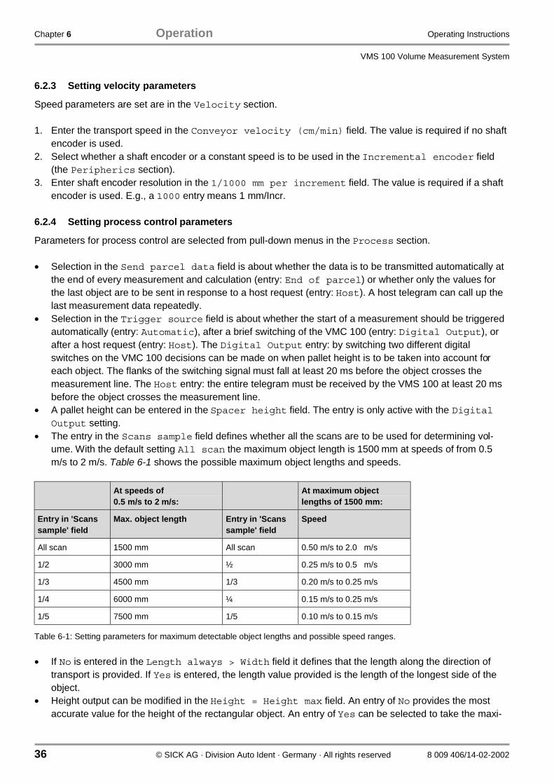
• The entry in the Scans sample field defines whether all the scans are to be used for determining vol-ume. With the default setting All scan the maximum object length is 1500 mm at speeds of from 0.5m/s to 2 m/s. Table 6-1 shows the possible maximum object lengths and speeds.
At speeds of0.5 m/s to 2 m/s:
At maximum objectlengths of 1500 mm:
Entry in 'Scanssample' field
Max. object length Entry in 'Scanssample' field
Speed
All scan 1500 mm All scan 0.50 m/s to 2.0 m/s
1/2 3000 mm ½ 0.25 m/s to 0.5 m/s
1/3 4500 mm 1/3 0.20 m/s to 0.25 m/s
1/4 6000 mm ¼ 0.15 m/s to 0.25 m/s
1/5 7500 mm 1/5 0.10 m/s to 0.15 m/s
Table 6-1: Setting parameters for maximum detectable object lengths and possible speed ranges.
• If No is entered in the Length always > Width field it defines that the length along the direction oftransport is provided. If Yes is entered, the length value provided is the length of the longest side of theobject.
• Height output can be modified in the Height = Height max field. An entry of No provides the mostaccurate value for the height of the rectangular object. An entry of Yes can be selected to take the maxi-

Operating Instructions Operation Chapter 6
VMS 100
8 009 406/14-02-2002 © SICK AG · Division Auto Ident · Germany · All rights reserved 37
mum height value more into account at speeds of less than 0.5 m/s, which can result in the values pro-vided being less accurate.
6.2.5 Setting optional device parameters
The VMS 100 Commissioning Software is informed about the optional connectable devices in the Peripher-ics section.
• If a bar-code reader is connected to the RS-485 interface of the VMC 100 as an auxiliary device it mustbe defined in the Barcode reader field (entry of No if no bar-code reader is connected). The followingtime window is available for receiving bar-code telegrams: the telegram starts no earlier than 20 ms afterthe object has crossed the measurement line, the telegram ends no later than 20 ms after the object hasleft the measurement line.
• The Weighter type field is used to define whether one of the selectable weighing machines is con-nected to the RS-485 interface of the VMC 100 as an auxiliary device (the entry No Weighter is usedwhen no scales are connected). This auxiliary device is contacted after the end of the object. Connectionshould be carried out by SICK Service.
• The Increm. encoder field is used to define whether a shaft encoder is used: No = no shaft encoder,Yes = operation with a shaft encoder.
• The Photocell field can be used to register an optional photoelectric switch at the VMS 100. Such aphotoelectric switch should be installed perpendicular to the direction of transport directly above themeasurement line of the LMS 200.
6.2.6 Data transfer
The handling of parameterisation data is defined in the Controls section.
• The Get values button inserts the parameterisation data available in the VMC 100 into the menu win-dow. Data previously entered in the menu window are deleted.
• The Default values button provides the fixed standard parameterisation data. These provide guide-lines for a standard application. Data previously entered in the menu window are deleted.
• The Send values buttons transmits the data visible in the menu window to the VMC 100. Data previ-ously available in the VMC 100 are deleted.
• The Exit button closes the menu window without triggering any data transfer.
6.3 Output of measurement data on the screen
VMS 100 measurement values can be received on the PC in real time after starting the VMS 100 Commis-sioning Software. This display is useful for testing the parameterisation – the display is not suitable for normalmeasurement operation. Click on the See Values entry in the sub-menu VMS 100 of the File menu. TheVolume Measurement System 100 menu window appears. The menu window shows the measurementdata and two buttons.
Under Volume Measurement there is:
• the Length field showing the length of the object,• the Width field with the width of the object, and• the Height field showing object height.

Chapter 6 Operation Operating Instructions
VMS 100 Volume Measurement System
38 © SICK AG · Division Auto Ident · Germany · All rights reserved 8 009 406/14-02-2002
Furthermore, the results of any optional connectable devices are also displayed if available:
• the Weight field may show the weight of the object,• the Barcode field may show the bar-code on the object. Display is limited to 15 characters.
As regards the buttons:
• The Test Request button transmits a telegram for measurement readiness.• The Exit button closes the window.
Fig. 6-3: Display of measurement data, an example after a restart.
6.4 Completion and test measurements
� Log all the parameters in the commissioning log and save the document somewhere safe.
Customers should select a typical measurement object for the test measurements, selecting the followingproperties:
• typical object surface material• typical object surface colour• typical object size
� Carry out several measurements with the object.Measure the object precisely with a measuring tape or metre-rule and note the values for its length, widthand height, and compare them with the VMS 100 measurement values.
� If necessary, reset the parameters.The output of the object dimension along the direction of transport can be optimised with the parametersConveyor velocity or 1/1000 mm per increment. The LMS/conveyor position parameteraffects the output of the height and the object dimension across the direction of transport of the object. ���� � ��� �� ����!���� �������� !�� � ������� ������ �! ������ ��������� "�� ��� ��� ����� # ��� ��
re-adjusted to optimise object dimension values across the direction of transport.
Recommendation:Parameterise and adjust the VMS 200 carefully to achieve high accuracies.

Operating Instructions Maintenance Chapter 7
VMS 100
8 009 406/14-02-2002 © SICK AG · Division Auto Ident · Germany · All rights reserved 39
7 Maintenance
7.1 Maintenance during operation
To retain maximum performance the LMS 200 Laser Measurement System needs a clean front window(reading window). A weekly front window contamination check is recommended in harsh operating environ-ments (dust, grindings, damp, etc.), in particular. More frequent checks may be required depending on theconditions. Clean the LMS 200 housing every six months to ensure sufficient cooling.
Contamination indicator:
Depending on the degree of front window contamination the LMS 200 provides the following warnings bymeans of the yellow LED (middle) and red LED (left):
LED behaviour Meaning
Yellow LED blinks at rate of 1 Hz,50% on and 50% off
Warning: weak contamination.The LMS 200 can still be used in this condition.
Yellow LED blinks at rate of 1 Hz,90% on and 10% off.The red LED is continuously lit
Contamination error: strong contamination.The LMS 200 is no longer capable of operation.
Table 7-1: LMS 200: LED error indicators on contamination of the front window.
Depending on the degree of front window contamination the VMC 100 also issues the following warning bymeans of the "MODE" LED:
"MODE" LED behaviour Meaning
Green / red blinking Warning (weak contamination).Measurement Mode still active.
Red blinking Error (strong contamination).The VMC 100 is no longer capable of operation.
Table 7-2: VMC 100: LED error indicators on contamination of the LMS front window.
Cleaning the front window of the LMS 200:
Damage to the front window!
The front window is made of plastic. System performance can be reduced as a result ofscratches and streaks on the front window.
� Use mild detergent without any powder.� Avoid scratching and scouring movements.
� Clean the front window at regular intervals, e.g. with an anti-static glass cleaning liquid. Use a soft, non-fluffy cloth for cleaning.
� If necessary also clean the LED indicators of the LMS 200 and the front panel of the VMC 100.
ATTENTION

Chapter 7 Maintenance Operating Instructions
VMS 100 Volume Measurement System
40 © SICK AG · Division Auto Ident · Germany · All rights reserved 8 009 406/14-02-2002
7.2 Maintenance
The VMS 100 operates without the need for maintenance. Any errors that crop up are reported by the systemvia the "MODE" LED on the front panel of the VMC 100 and by the output of the device status, separately forthe LMS 200 and the VMC 100, in the measurement results. See also Table 7-2 and Chapter 3.3.2 Functionsof the LED indicators.
Test measurement:
A test measurement every month is recommended with a typical rectangular reference object with knowndimensions.
� Measure the object several times with the VMS 100 and compare the values received with the knownobject dimensions.
7.3 Disposal
Dispose of unusable or irreparable devices in an environmentally friendly manner after a final decommission-ing:
1. Follow valid local waste disposal regulations.2. Dismantle the housing.3. Dismantle the electronic assemblies.4. Remove the front window (LMS 200) and dispose of it for plastic recycling.5. Remove the chassis and dispose of it for aluminium die cast recycling.6. Dispose of the electronic assemblies as special waste.7. Dispose of cable wiring for metal recycling
SICK AG does not currently accept the return of devices that are unusable or irreparable.

Operating Instructions Troubleshooting Chapter 8
VMS 100
8 009 406/14-02-2002 © SICK AG · Division Auto Ident · Germany · All rights reserved 41
8 Troubleshooting
8.1 Overview of possible faults and problems
8.1.1 Mounting error
• The LMS 200 is not well aligned upon the object on the transport system• The shaft encoder (optional) is wrongly sited
8.1.2 Error in the electrical installation
• VMC 100 data interface (COM connection) wrongly wired• Bad connection between LMS 200 and VMC 100
8.1.3 Parameterisation error
• Functions not adapted to the conditions on site• Trigger source wrongly selected• Technical device limits not taken sufficiently into account
8.1.4 Operating difficulties
• Object gap too small• Device fault (hardware/software)
8.2 Monitoring signs of faults and problems
The VMS 100 monitors itself during operation:
• After switching on the power supply the VMS 100 carries out a self-test before initialisation (loading of theparameter set and initialisation of the device functions) involving the testing of important hardware com-ponents.
• If the VMS 100 discovers a device fault during the self-test or during self-monitoring, the VMC 100 givesout appropriate numerical values in the measurement result output telegram for VMC 100 status and LMS200 device status in a coded form.See Chapter 10.2.2 VMC 100 status and 10.2.3 LMS 200 device status.
• The red and yellow LEDs of the LMS 200 and the "Mode" LED of the VMC 100 signal the system's errorstate.See Chapter 3.3.2 Functions of the LED indicators.
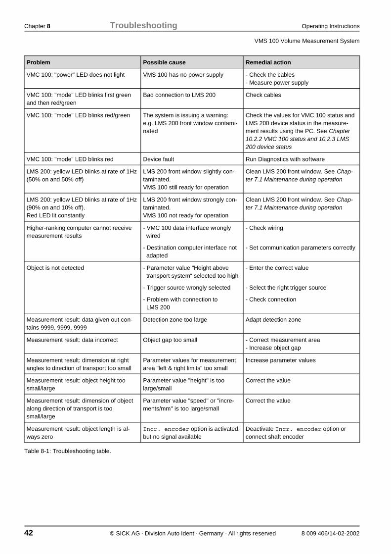
8.3 Identifying faults and remedying them
The following aids are necessary for remedying the faults described in the table below:
• these Operating Instructions• tools• a measuring tape (up to 2000 mm)• a digital measurement device (current / voltage measurements)• a PC with VMS 100 Commissioning Software• RS-232 data connection cable, e.g. order no. 2 016 401
Chapter 8 Troubleshooting Operating Instructions
VMS 100 Volume Measurement System
42 © SICK AG · Division Auto Ident · Germany · All rights reserved 8 009 406/14-02-2002
Problem Possible cause Remedial action
VMC 100: "power" LED does not light VMS 100 has no power supply - Check the cables- Measure power supply
VMC 100: "mode" LED blinks first greenand then red/green
Bad connection to LMS 200 Check cables
VMC 100: "mode" LED blinks red/green The system is issuing a warning:e.g. LMS 200 front window contami-nated
Check the values for VMC 100 status andLMS 200 device status in the measure-ment results using the PC. See Chapter10.2.2 VMC 100 status and 10.2.3 LMS200 device status
VMC 100: "mode" LED blinks red Device fault Run Diagnostics with software
LMS 200: yellow LED blinks at rate of 1Hz(50% on and 50% off)
LMS 200 front window slightly con-taminated.VMS 100 still ready for operation
Clean LMS 200 front window. See Chap-ter 7.1 Maintenance during operation
LMS 200: yellow LED blinks at rate of 1Hz(90% on and 10% off).Red LED lit constantly
LMS 200 front window strongly con-taminated.VMS 100 not ready for operation
Clean LMS 200 front window. See Chap-ter 7.1 Maintenance during operation
Higher-ranking computer cannot receivemeasurement results
- VMC 100 data interface wrongly wired
- Destination computer interface not adapted
- Check wiring
- Set communication parameters correctly
Object is not detected - Parameter value "Height above transport system“ selected too high
- Trigger source wrongly selected
- Problem with connection to LMS 200
- Enter the correct value
- Select the right trigger source
- Check connection
Measurement result: data given out con-tains 9999, 9999, 9999
Detection zone too large Adapt detection zone
Measurement result: data incorrect Object gap too small - Correct measurement area- Increase object gap
Measurement result: dimension at rightangles to direction of transport too small
Parameter values for measurementarea "left & right limits" too small
Increase parameter values
Measurement result: object height toosmall/large
Parameter value "height" is toolarge/small
Correct the value
Measurement result: dimension of objectalong direction of transport is toosmall/large
Parameter value "speed" or "incre-ments/mm" is too large/small
Correct the value
Measurement result: object length is al-ways zero
Incr. encoder option is activated,but no signal available
Deactivate Incr. encoder option orconnect shaft encoder
Table 8-1: Troubleshooting table.

Operating Instructions Troubleshooting Chapter 8
VMS 100
8 009 406/14-02-2002 © SICK AG · Division Auto Ident · Germany · All rights reserved 43
8.4 SICK Support
If a fault cannot be remedied by any of the above-mentioned measures, the VMS 100 may be defective. Thesystem does not contain any components whose functionality can be restored by the user repairing them aftera breakdown.
Please contact your local SICK office or subsidary:
• The telephone and fax numbers are listed on the back page of these Operating Instructions.
� Please do not send in the device without contacting SICK Service.
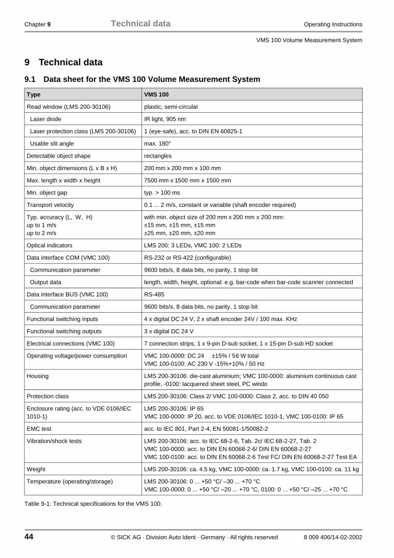
Chapter 9 Technical data Operating Instructions
VMS 100 Volume Measurement System
44 © SICK AG · Division Auto Ident · Germany · All rights reserved 8 009 406/14-02-2002
9 Technical data
9.1 Data sheet for the VMS 100 Volume Measurement System
Type VMS 100
Read window (LMS 200-30106) plastic, semi-circular
Laser diode IR light, 905 nm
Laser protection class (LMS 200-30106) 1 (eye-safe), acc. to DIN EN 60825-1
Usable slit angle max. 180°
Detectable object shape rectangles
Min. object dimensions (L x B x H) 200 mm x 200 mm x 100 mm
Max. length x width x height 7500 mm x 1500 mm x 1500 mm
Min. object gap typ. > 100 ms
Transport velocity 0.1 ... 2 m/s, constant or variable (shaft encoder required)
Typ. accuracy (L, W, H)up to 1 m/sup to 2 m/s
with min. object size of 200 mm x 200 mm x 200 mm:±15 mm, ±15 mm, ±15 mm±25 mm, ±20 mm, ±20 mm
Optical indicators LMS 200: 3 LEDs, VMC 100: 2 LEDs
Data interface COM (VMC 100) RS-232 or RS-422 (configurable)
Communication parameter 9600 bits/s, 8 data bits, no parity, 1 stop bit
Output data length, width, height, optional: e.g. bar-code when bar-code scanner connected
Data interface BUS (VMC 100) RS-485
Communication parameter 9600 bits/s, 8 data bits, no parity, 1 stop bit
Functional switching inputs 4 x digital DC 24 V, 2 x shaft encoder 24V / 100 max. KHz
Functional switching outputs 3 x digital DC 24 V
Electrical connections (VMC 100) 7 connection strips, 1 x 9-pin D-sub socket, 1 x 15-pin D-sub HD socket
Operating voltage/power consumption VMC 100-0000: DC 24 ±15% / 56 W totalVMC 100-0100: AC 230 V -15%+10% / 50 Hz
Housing LMS 200-30106: die-cast aluminium; VMC 100-0000: aluminium continuous castprofile, -0100: lacquered sheet steel, PC windo
Protection class LMS 200-30106: Class 2/ VMC 100-0000: Class 2, acc. to DIN 40 050
Enclosure rating (acc. to VDE 0106/IEC1010-1)
LMS 200-30106: IP 65VMC 100-0000: IP 20, acc. to VDE 0106/IEC 1010-1, VMC 100-0100: IP 65
EMC test acc. to IEC 801, Part 2-4; EN 50081-1/50082-2
Vibration/shock tests LMS 200-30106: acc. to IEC 68-2-6, Tab. 2c/ IEC 68-2-27, Tab. 2VMC 100-0000: acc. to DIN EN 60068-2-6/ DIN EN 60068-2-27VMC 100-0100: acc. to DIN EN 60068-2-6 Test FC/ DIN EN 60068-2-27 Test EA
Weight LMS 200-30106: ca. 4.5 kg, VMC 100-0000: ca. 1.7 kg, VMC 100-0100: ca. 11 kg
Temperature (operating/storage) LMS 200-30106: 0 ... +50 °C/ –30 ... +70 °CVMC 100-0000: 0 ... +50 °C/ –20 ... +70 °C, 0100: 0 ... +50 °C/ –25 ... +70 °C
Table 9-1: Technical specifications for the VMS 100.

Operating Instructions Technical data Chapter 9
VMS 100
8 009 406/14-02-2002 © SICK AG · Division Auto Ident · Germany · All rights reserved 45
9.2 Dimensional drawings
9.2.1 LMS 200-30106 Laser Measurement System dimensional drawing
Fig. 9-1: Dimensions of the LMS 200-30106 Laser Measurement System
All dimensions in mm

Chapter 9 Technical data Operating Instructions
VMS 100 Volume Measurement System
46 © SICK AG · Division Auto Ident · Germany · All rights reserved 8 009 406/14-02-2002
9.2.2 VMC 100-0000 evaluation unit dimensional drawing
Fig. 9-2: Dimensions of the VMC 100-0000 evaluation unit
All dimensions in mm
Mounting SetMounting Set
foot for standardmounting rail
max. 187 (variable distance)

Operating Instructions Technical data Chapter 9
VMS 100
8 009 406/14-02-2002 © SICK AG · Division Auto Ident · Germany · All rights reserved 47
9.2.3 View of Mounting Set for LMS 200-30106
Fig. 9-3: Structure of Mounting Set no. 2 020 925

Chapter 9 Technical data Operating Instructions
VMS 100 Volume Measurement System
48 © SICK AG · Division Auto Ident · Germany · All rights reserved 8 009 406/14-02-2002
9.2.4 View of VMC 100-0100
Fig. 9-4: Dimensions of the VMC 100-0100 evaluation unit.
All dimensions in mm

Operating Instructions Appendix Chapter 10
VMS 100
8 009 406/14-02-2002 © SICK AG · Division Auto Ident · Germany · All rights reserved 49
10 Appendix
10.1 Overview of the Appendix
The appendix contains the following supplements and auxiliary information:
• Telegram structure• System or component replacement• Available accessories (order details)• Information on supplementary documentation• The EU Declaration of Conformity• Index
10.2 Telegram structure
10.2.1 Telegram format
The telegram given out by the VMC 100 as the measurement result via its COM data interface, is composedas follows in Tab. 10-1 from the top downwards:
Description Bytes Meaning
Header 8 Header, beginning with ST
Object length in mm 4 ASCII data
Separator 1 09(hex)
Object width in mm 4 ASCII data
Separator 1 09(hex)
Object height in mm 4 ASCII data
Separator 1 09(hex)
Object weight in kg 4 ASCII data
Separator 1 09(hex)
Bar-code length 2 ASCII data
Separator 1 09(hex)
Bar code n ASCII data
Separator 1 09(hex)
Device status 1 he
VMC 100 status 1 he
Checksum 2 CRC 16
Table 10-1: Telegram format at the COM data interface (VMC 100).
The VMS 100 can receive an external telegram during Measurement Mode and integrate it in the output tele-gram. The entire external telegram must be received by the VMC 100 during the measurement of the object.A measurement is active while an object is on the measurement line.
The structure of a telegram that can be sent from an auxiliary device to the RS-485 interface of the VMS 100,is defined as follows:

Chapter 10 Appendix Operating Instructions
VMS 100 Volume Measurement System
50 © SICK AG · Division Auto Ident · Germany · All rights reserved 8 009 406/14-02-2002
Description Bytes Meaning
Start characters 1 STX
Number of characters in barcode
2 Separator, CL code length, before code(trigger for digital in: flank high)
Bar code Length depending on application
Block check (BCC) Block check, XOR linkage via all preceding characters(hex-ASCII format)
End characters 1 ETX
Table 10-2: Structure of external telegrams.
10.2.2 VMC 100 status
The VMC 100 device status transferred in the telegram has the following meaning:
Code Meaning
0 Normal Measurement Mode
1 Warning: LMS window contaminated
2 Problem LMS 200
3 Problem bar-code scanner
4 Problem weighing machine
Table 10-3: Output telegram: meaning of the VMC 100 status.
10.2.3 LMS 200 device status
In the LMS 200 status byte information is provided bit-wise.
Bit Meaning
0 - 2 Classification:0 = Normal Measurement Mode1 = Information2 = Warning3 = Error4 = Fatal error
3 - 4 Cause:0 = Software VMC 1001 = Software VMS 1002 = LMS 2003 = Not used (reserved)
5 Contamination:0 = None1 = Contamination of LMS windo
6 - 7 Not used (reserved)
Table 10-4: Output telegram: meaning of the LMS 200 device status.

Operating Instructions Appendix Chapter 10
VMS 100
8 009 406/14-02-2002 © SICK AG · Division Auto Ident · Germany · All rights reserved 51
Triggering measurement readiness with a telegram from the host:
If the system is in "Limited measurement readiness" mode (Request) measurement readiness is activated bythe following telegram to the VMC 100: 02 00 08 00 7D 74 08 06 C0 01 00 07 8F 56See also the Test Request button in Fig. 6-3 in Chapter 6.3 Output of measurement data on the screen.The telegram shown above is sent to the VMC 100 by pressing this button.
Request for measurement values with telegram from host
The measurement values of the VMS 100 can be requested with the following telegram:02 00 08 00 7D 74 08 06 C0 01 00 02 8A 56. The telegram can be sent to the VMS 100 several times forrepeated requests.
10.2.4 Replacing a system or components
Proceed as follows if the system or individual components need replacement:
LMS 200:
1. Switch off VMC 100 power supply.2. Loosen and remove the plug modules of both connection cables on the LMS 200.3. Loosen and remove the Mounting Set screws on the LMS 200 and remove the device.4. Mount and connect the replacement device appropriately.5. Switch on the VMC 100 power supply.6. Connect PC to the VMC 100 "COM" connection via the data cable and start up PC.7. Start the VMS 100 Commissioning Software and completely reset the system parameters as described in
Chapter 6.This ensures that a high level of measurement accuracy is also achieved with the new LMS 200.
VMC 100:
1. Note all the parameters with the help of the Commissioning Software.2. Switch off the VMC 100 power supply.3. Remove all connection cables on the VMC 100.4. Disassemble the VMC 100. Unscrew the VMC 100-0000 with its wall bracket from the base or unclip the
VMC 100-0000 from the mounting rail. Or remove the VMC 100-0100 from the attachment equipment.5. If necessary remove the VMC 100 from the wall bracket.6. Mount the new device. First screw the new VMC 100-0000 onto the wall bracket and then together with it
onto the base, or snap the device onto the mounting rail. Or mount the VMC-0100 onto the attachmentequipment.
7. Re-attach all the connection cables to the VMC 100.8. Switch on the VMC 100 power supply.9. Connect the PC to the VMC 100 COM connection via the data cable and start the PC up.10. Start the VMS 100 Commissioning Software and enter the parameters that were noted before with the
parameterisation software or completely reset the system parameters as described in Chapter 6.
See Chapter 7.3 Disposal for disposal of unusable or irreparable devices.

Chapter 10 Appendix Operating Instructions
VMS 100 Volume Measurement System
52 © SICK AG · Division Auto Ident · Germany · All rights reserved 8 009 406/14-02-2002
10.3 Available accessories (order details)
10.3.1 The complete VMS 100 systems
Order no. Description
1 022 987 The complete VMS 100-0000 system, consisting of:
- 1 LMS 200-30106 Laser Measurement System
- 1 Connection Set 2 for the LMS 200:2 cables for electrical supply and data transfer, each 10 m long,with one connection plug module each for the LMS 200
- 1 Mounting Set, two-axis, fine adjustment
- 1 VMC 100-0000 evaluation unit with installed VMS 100 Evaluation Software, for clip-on mounting rail, witha mounting set for wall mounting
- 1 diskette (3½ inch) with VMS 100 Commissioning Software for Windows-NT/Windows 95
Table 10-5: Order details: the complete VMS 100 system.
Also available on request as a device version, with VMC 100-0100 in an IP 65 protective cabinet with powersupply. 10.3.2 Accessories
Optional accessories for operation:
Order no. Description
On request Photoelectric switch
On request Shaft encoder, resolution min. 1 mm
On request Bar-code scanner
On request Power supply unit
On request Adapter for connection to Bus systems
2 019 522 Heating plate for LMS 200 for operation between –12°C ...+50°C, though no LMS operation outdoors230 VAC ± 10 %, 30 W (cyclic, thermostat-controlled), IP 65
Table 10-6: Order details: optional accessories for operation.
Accessories for commissioning:
Order no. Description
2 016 401 Data cable for connection of PC/Laptop to VMC 100, with 2 x 9-pin D-sub plugs, length 3 m (RS-232male/female-crossed)
6 020 756 Scan finder
Table 10-7: Order details: optional accessories for commissioning.
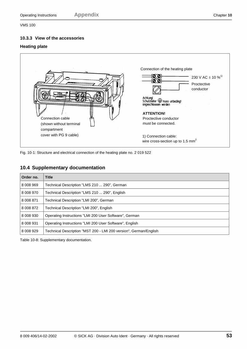
Operating Instructions Appendix Chapter 10
VMS 100
8 009 406/14-02-2002 © SICK AG · Division Auto Ident · Germany · All rights reserved 53
10.3.3 View of the accessories
Heating plate
Fig. 10-1: Structure and electrical connection of the heating plate no. 2 019 522
10.4 Supplementary documentation
Order no. Title
8 008 969 Technical Description "LMS 210 ... 290", German
8 008 970 Technical Description "LMS 210 ... 290", English
8 008 871 Technical Description "LMI 200", German
8 008 872 Technical Description "LMI 200", English
8 008 930 Operating Instructions "LMI 200 User Software", German
8 008 931 Operating Instructions "LMI 200 User Software", English
8 008 929 Technical Description "MST 200 - LMI 200 version“, German/English
Table 10-8: Supplementary documentation.
Connection of the heating plate
Connection cable
(shown without terminal
compartment
cover with PG 9 cable)
ATTENTION!Proctective conductormust be connected.
230 V AC ± 10 %1)
Proctectiveconductor
1) Connection cable:wire cross-section up to 1.5 mm2

Chapter 10 Appendix Operating Instructions
VMS 100 Volume Measurement System
54 © SICK AG · Division Auto Ident · Germany · All rights reserved 8 009 406/14-02-2002
10.5 The EU Declaration of Conformit
10.5.1 The LMS 200 EU Declaration of Conformit
Fig. 10-2: The EU Declaration of Conformity for the LMS 200, Page 3 (reduced in size).

Operating Instructions Appendix Chapter 10
VMS 100
8 009 406/14-02-2002 © SICK AG · Division Auto Ident · Germany · All rights reserved 55
Fig. 10-3: The EU Declaration of Conformity for the LMS 200, Page 2 (reduced in size).
SICK AG Telefon (0 7641) 469-0 Aufsichtsratsvorsitzender: Sitz: Waldkirch i.Br.Nimburger Str. 11 Telefax (0 76 41) 469-149 Dr. Horst Skoludek HandelsregisterD-79276 Reute Vorstand: Emmendingen HRB 355 W
Volker Reiche (Vors.)Anne-Kathrin DeutrichDieter Fischer
The EC Declaration of Conformity No. 9055675 is valid for the following types of the product family LMS:
Type Id.-No.
LMS200-30106 1015850
LMS210-20201 1013859
LMS210-20202 1013856
LMS210-20204 1013860
LMS210-30206 1017812
LMS211-20201 1013853
LMS211-20202 1013854
LMS211-20204 1013855
LMS211-30206 1018023
LMS220-20203 1013865
LMS220-30106 1015945
LMS220-30206 1017811
LMS221-20203 1015833
LMS221-30206 1018022
LMS290-S01 1016024
LMS291-S01 1016078
LMS209-S02 1016414
LMS299-S03 1016829
LMS200-S04 1016828
LMS290-S05 1018027
LMS291-S05 1018028
LMS219-S06 1018761
LMS229-S06 1018764
LMS211-S07 1018966
LMS221-S07 1018965
end of list -
Mat.-No.: 9 055 675Page 2
Update no.: K438

Chapter 10 Appendix Operating Instructions
VMS 100 Volume Measurement System
56 © SICK AG · Division Auto Ident · Germany · All rights reserved 8 009 406/14-02-2002
10.5.2 The VMC 100 EU Declaration of Conformit
Fig. 10-4: The EU Declaration of Conformity for the VMC 100, Page 3 (reduced in size).
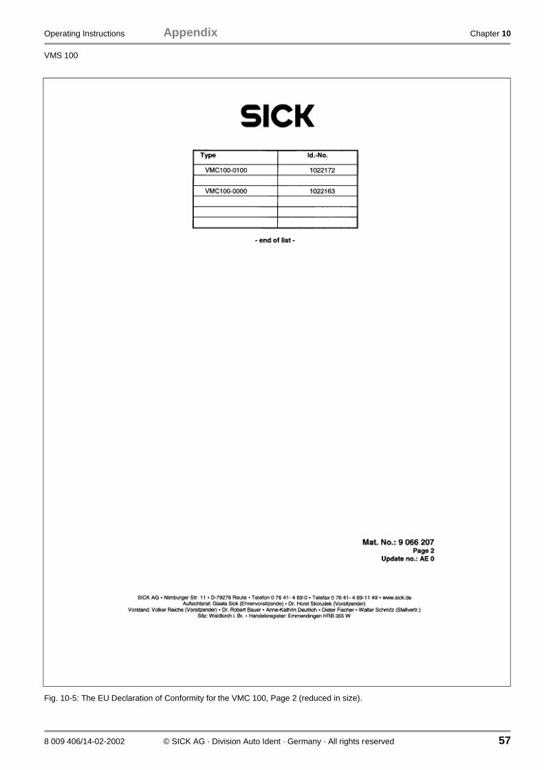
Operating Instructions Appendix Chapter 10
VMS 100
8 009 406/14-02-2002 © SICK AG · Division Auto Ident · Germany · All rights reserved 57
Fig. 10-5: The EU Declaration of Conformity for the VMC 100, Page 2 (reduced in size).
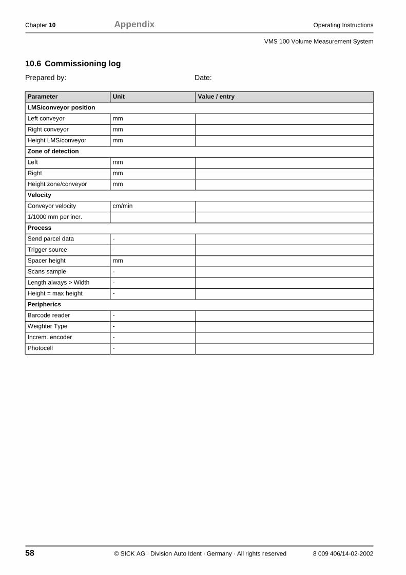
Chapter 10 Appendix Operating Instructions
VMS 100 Volume Measurement System
58 © SICK AG · Division Auto Ident · Germany · All rights reserved 8 009 406/14-02-2002
10.6 Commissioning log
Prepared by: Date:
Parameter Unit Value / entry
LMS/conveyor position
Left conveyor mm
Right conveyor mm
Height LMS/conveyor mm
Zone of detection
Left mm
Right mm
Height zone/conveyor mm
Velocity
Conveyor velocity cm/min
1/1000 mm per incr.
Process
Send parcel data -
Trigger source -
Spacer height mm
Scans sample -
Length always > Width -
Height = max height -
Peripherics
Barcode reader -
Weighter Type -
Increm. encoder -
Photocell -
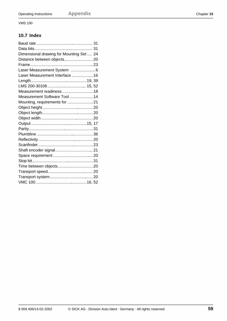
Operating Instructions Appendix Chapter 10
VMS 100
8 009 406/14-02-2002 © SICK AG · Division Auto Ident · Germany · All rights reserved 59
10.7 Index
Baud rate .................................................. 31Data bits.................................................... 31Dimensional drawing for Mounting Set .... 24Distance between objects..........................20Frame.........................................................23Laser Measurement System ......................6Laser Measurement Interface ...................16Length..................................................19, 39LMS 200-30106 ................................... 15, 52Measurement readiness............................18Measurement Software Tool .....................14Mounting, requirements for .......................21Object height..............................................20Object length..............................................20Object width ...............................................20Output ..................................................15, 17Parity..........................................................31Plumbline ...................................................36Reflectivity .................................................20Scanfinder..................................................23Shaft encoder signal.................................. 21Space requirement .................................... 20Stop bit.......................................................31Time between objects................................20Transport speed......................................... 20Transport system....................................... 20VMC 100..............................................16, 52

SICK AG · Division Auto Ident · Nimburger Straße 11 · 79276 Reute · Germany · www.sick.de8 0
09
40
6/1
4-0
2-2
00
2 · 5
M/T
R <
Win
W9
7/P
M 6
.0>
· S
MD
· P
rinte
d in G
erm
any
· A
ftE3
30
5sw
A u s t r a l i aPhone +61 3 9497 4100
(0 08) 33 48 02–toll free
Fax +61 3 9497 1187
A u s t r i aPhone +43 22 36/62 28 8-0
Fax +43 22 36/62 28 85
B e l g i u m / L u x e m b o u r gPhone +32 24 66 55 66
Fax +32 24 63 31 04
Laser Measurement Systems:
Phone +32 9 2240 394
Fax +32 9 2235 645
B r a z i lPhone +55 11 5561 2683
Fax +55 11 5535 4153
C h i n aPhone +85 2 2763 6966
Fax +85 2 2763 6311
C z e c h R e p u b l i cPhone +42 02-579 11 850
+42 02-578 10 561
Fax +42 02-578 10 559
D e n m a r kPhone +45 45 82 64 00
Fax +45 45 82 64 01
F i n l a n dPhone +358 9-728 85 00
Fax +358 9-72 88 50 55
F r a n c ePhone +33 1 64 62 35 00
Fax +33 1 64 62 35 77
G e r m a n yPhone (+49 2 11) 53 01-0
Fax (+49 2 11) 53 01-1 00
G r e a t B r i t a i nPhone +44 17 27-83 11 21
Fax +44 17 27-85 67 67
I t a l yPhone +39 02-92 14 20 62
Fax +39 02-92 14 20 67
J a p a nPhone +81 3 3358 1341
Fax +81 3 3358 0586
N e t h e r l a n d sPhone +31 30 229 25 44
Fax +31 30 229 39 94
Laser Measurement Systems:
Phone +31 73 599 50 44
Fax +31 73 599 47 18
N o r w a yPhone +47 67 56 7500
Fax +47 67 56 6100
P o l a n dPhone +48 22 837 40 50
Fax +48 22 837 43 88
S i n g a p o r ePhone +65 744 3732
Fax +65 841 7747
S p a i nPhone +34 93 4 80 31 00
Fax +34 93 4 73 44 69
S w e d e nPhone +46 8-680 64 50
Fax +46 8-710 18 75
S w i t z e r l a n dPhone +41 41 61 92 93 9
Fax +41 41 61 92 92 1
T a i w a nPhone +886 2 2365-6292
Fax +886 2 2368-7397
U S APhone +1(952) 941-6780
Fax +1(952) 941-9287
Representatives and agencies in all major industrial countries.