Embed Size (px)
Citation preview

VMware Cloud FoundationArchitecture and Deployment Guide
VMware Cloud Foundation 3.0
You can find the most up-to-date technical documentation on the VMware website at:
https://docs.vmware.com/
If you have comments about this documentation, submit your feedback to
VMware, Inc.3401 Hillview Ave.Palo Alto, CA 94304www.vmware.com
Copyright © 2015 - 2018 VMware, Inc. All rights reserved. Copyright and trademark information.
VMware Cloud Foundation Architecture and Deployment Guide
VMware, Inc. 2
Contents
About the VMware Cloud Foundation Architecture and Deployment Guide 4
1 About VMware Cloud Foundation 5Cloud Foundation Components 6
SDDC Manager 6
VMware vSphere 6
VMware vSAN 6
NSX for vSphere 6
vRealize Suite 7
Simplified Resource Provisioning with Workload Domains 7
Automated Software Bring-Up 8
Automated Lifecycle Management 8
2 Cloud Foundation Architecture 9Standard Architecture Model 9
Consolidated Architecture Model 10
3 Preparing your Environment for Cloud Foundation 11
4 Deploying Cloud Foundation 12Deploy Cloud Foundation Builder VM 13
Download and Complete Deployment Parameter Sheet 15
About the Deployment Parameter Sheet 15
Generate JSON File 23
Initiate the Cloud Foundation Bring-Up Process 24
5 Troubleshooting Cloud Foundation Deployment 27SoS Tool Options for Cloud Builder 27
Bring-Up Log Files 31
6 Cloud Foundation Glossary 32
VMware, Inc. 3

About the VMware Cloud FoundationArchitecture and Deployment Guide
The VMware Cloud Foundation Architecture and Deployment Guide provides a high-level overview of theVMware Cloud Foundation product and its architecture. This document also describes the deploymentprocess for Cloud Foundation.
Intended AudienceThe VMware Cloud Foundation Architecture and Deployment Guide is intended for data center cloudadministrators who deploy a Cloud Foundation system in their organization's data center. The informationin this guide is written for experienced data center cloud administrators who are familiar with:
n Concepts of virtualization and software-defined data centers
n Networking and concepts such as uplinks, NICs, and IP networks
n Hardware components such as top-of-rack (ToR) switches, inter-rack switches, servers with directattached storage, cables, and power supplies
n Methods for setting up physical racks in your data center
n Using the VMware vSphere® Web Client™ to work with virtual machines
Related PublicationsThe VMware Cloud Foundation Planning and Preparation Guide provides detailed information about thesoftware, tools, and external services that are required for Cloud Foundation.
The VMware Cloud Foundation Operations and Administration Guide contains detailed information abouthow to administer and operate a Cloud Foundation system in your data center.
Your Cloud Foundation system includes various VMware software products and components. You canfind the documentation for those VMware software products at docs.vmware.com.
Cloud Foundation GlossaryThe Cloud Foundation Glossary defines terms specific to Cloud Foundation.
VMware, Inc. 4
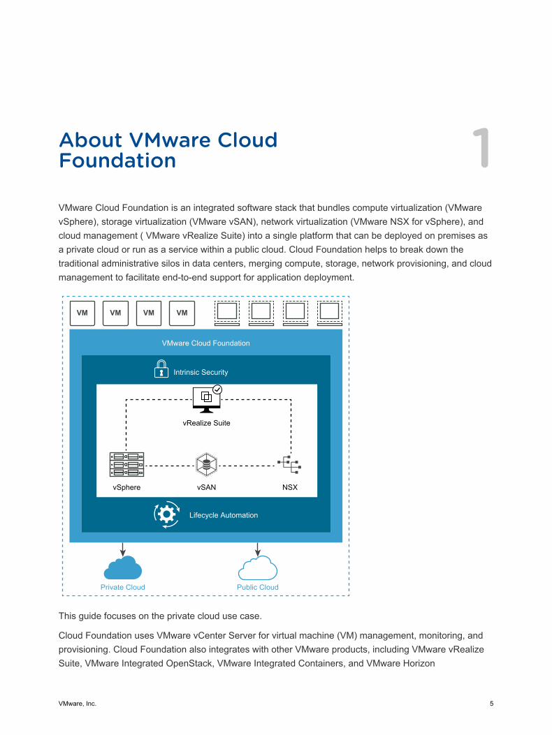
About VMware CloudFoundation 1VMware Cloud Foundation is an integrated software stack that bundles compute virtualization (VMwarevSphere), storage virtualization (VMware vSAN), network virtualization (VMware NSX for vSphere), andcloud management ( VMware vRealize Suite) into a single platform that can be deployed on premises asa private cloud or run as a service within a public cloud. Cloud Foundation helps to break down thetraditional administrative silos in data centers, merging compute, storage, network provisioning, and cloudmanagement to facilitate end-to-end support for application deployment.
VM VM VM VM
VMware Cloud Foundation
Intrinsic Security
Lifecycle Automation
Private Cloud Public Cloud
vRealize Suite
vSphere vSAN NSX
This guide focuses on the private cloud use case.
Cloud Foundation uses VMware vCenter Server for virtual machine (VM) management, monitoring, andprovisioning. Cloud Foundation also integrates with other VMware products, including VMware vRealizeSuite, VMware Integrated OpenStack, VMware Integrated Containers, and VMware Horizon
VMware, Inc. 5
To manage the logical infrastructure in the private cloud, Cloud Foundation augments the VMwarevirtualization and management components with a new component, SDDC Manager. SDDC Managerautomates the bring up, configuration, provisioning, and lifecycle management of the entire SDDC stack.From this interface, the IT administrator can provision new private cloud resources, monitor changes tothe logical infrastructure, and manage life cycle and other operational activities.
Cloud Foundation enables data center cloud administrators to provision an application environment in arapid, repeatable, automated way versus the traditional manual process.
This chapter includes the following topics:
n Cloud Foundation Components
n Simplified Resource Provisioning with Workload Domains
n Automated Software Bring-Up
n Automated Lifecycle Management
Cloud Foundation ComponentsCloud Foundation delivers a natively integrated software-defined data center stack that includes the coreinfrastructure virtualization, vSphere, vSAN and NSX.
SDDC ManagerSDDC Manager automates the entire system lifecycle (from initial bring-up, to configuration andprovisioning, to upgrades and patching), and simplifies day-to-day management and operations.
VMware vSphereVMware vSphere uses virtualization to transform individual data centers into aggregated computinginfrastructures that include CPU, storage, and networking resources. VMware vSphere manages theseinfrastructures as a unified operating environment and provides you with the tools to administer the datacenters that participate in that environment.
The two core components of vSphere are ESXi and vCenter Server. ESXi is the virtualization platformwhere you create and run virtual machines and virtual appliances. vCenter Server is the service throughwhich you manage multiple hosts connected in a network and pool host resources.
VMware vSANVMware vSAN™ aggregates local or direct-attached data storage devices to create a single storage poolshared across all hosts in the vSAN cluster. vSAN eliminates the need for external shared storage, andsimplifies storage configuration and virtual machine provisioning. Built in policies allow for flexibility indata availability.
NSX for vSphereNSX for vSphere provides networking and security functionality for your vSphere environment whichallows networks and network services to be abstracted from the physical infrastructure. The ability to
VMware Cloud Foundation Architecture and Deployment Guide
VMware, Inc. 6
manage the network through software allows for rapid changes and increased security policies to beimplemented.
vRealize SuiteCloud Foundation is integrated with the vRealize Suite of products.
vRealize Log InsightLog Insight delivers heterogeneous and highly scalable log management with intuitive and actionabledashboards, sophisticated analytics, and broad third-party extensibility. It provides deep operationalvisibility and faster troubleshooting across physical, virtual and cloud environments.
Log Insight is installed by default for the management domain. You can add licenses to enable Log Insightfor VI workload domains.
vRealize AutomationvRealize Automation is a cloud automation tool that accelerates the delivery of IT services throughautomation and pre-defined policies, providing high level of agility and flexibility for developers, whileenabling IT teams to maintain frictionless governance and control. This is an optional component.
vRealize Operations ManagervRealize Operations Manager delivers intelligent operations management with application-to-storagevisibility across physical, virtual, and cloud infrastructures. Using policy-based automation, operationsteams automate key processes and improve IT efficiency. This is an optional component.
Simplified Resource Provisioning with Workload DomainsCloud Foundation introduces a new abstraction, workload domains, for creating logical pools acrosscompute, storage, and networking. A workload domain consists of one or more vSphere clusters,provisioned automatically by SDDC Manager.
There are two types of workload domains - the management domain and VI workload domains.
The management domain is created during the bring-up process. It contains the Cloud Foundationmanagement components. This includes an instance of vCenter Server and required NSX components(NSX Manager and three NSX Controller VM) for the management domain. All vRealize Suitecomponents, such as vRealize Log Insight, vRealize Operations Manager and vRealize Automation, areinstalled in the management domain.
Cloud Foundation implements Virtual Infrastructure (VI) workload domains for user workloads. A VIworkload domain can consist of one or more vSphere clusters. Each cluster starts with a minimum ofthree hosts and can scale up to the vSphere and vSAN maximums. SDDC manager automates creationof the workload domain and the underlying vSphere cluster(s). Each cluster is assigned user specifiedvSphere HA policy and vSAN failures to tolerate (FTT) values along with full network configuration bySDDC Manager during the workload domain creation. SDDC Manager also deploys three NSX controllerVMs for each VI workload domain. These controller VMs communicate with a dedicated NSX Managerdeployed in the management domain.
VMware Cloud Foundation Architecture and Deployment Guide
VMware, Inc. 7
For each VI workload domain created, an additional vCenter Server instance and NSX Manager instanceis deployed in the management domain to manage that VI workload domain.
Automated Software Bring-UpYou prepare your environment for Cloud Foundation by installing a baseline ESXi image on vSANReadyNodes. After the hosts are physically racked and cabled, Cloud Foundation uses the physicalnetwork details you provide (such as DNS, IP address pool, and so on) to automate the bring-up andconfiguration of the software stack. During bring-up, the management domain is created on the four hostsyou specified. When the bring-up process completes, you have a functional management domain and canstart provisioning VI workload domains.
Automated Lifecycle ManagementSDDC Manager automates upgrade and patch management for the SDDC software stack.
VMware provides update bundles for the entire SDDC stack, ensuring compatibility of all patches withinstalled components in your Cloud Foundation environment. You can apply an update to themanagement domain or VI workload domains independent of the other workload domains. This makesthe process non-disruptive to tenant VMs.
VMware Cloud Foundation Architecture and Deployment Guide
VMware, Inc. 8
Cloud Foundation Architecture 2Cloud Foundation supports two architecture models - standard and consolidated.
This chapter includes the following topics:
n Standard Architecture Model
n Consolidated Architecture Model
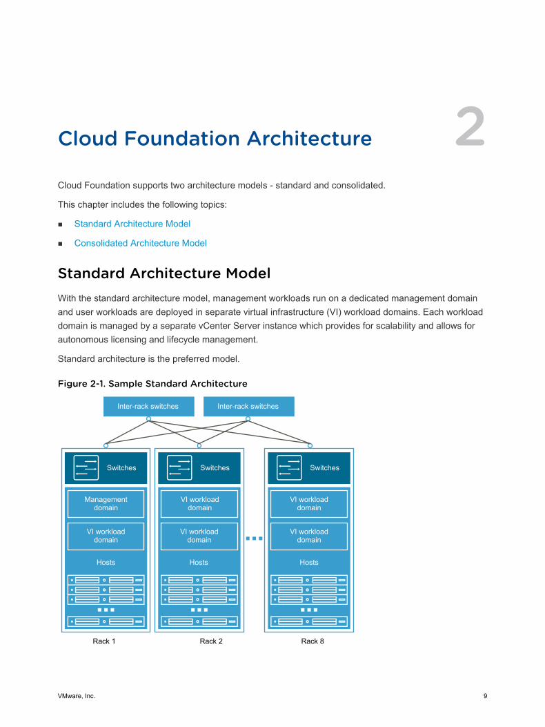
Standard Architecture ModelWith the standard architecture model, management workloads run on a dedicated management domainand user workloads are deployed in separate virtual infrastructure (VI) workload domains. Each workloaddomain is managed by a separate vCenter Server instance which provides for scalability and allows forautonomous licensing and lifecycle management.
Standard architecture is the preferred model.
Figure 2-1. Sample Standard Architecture
Switches
Hosts Hosts
Managementdomain
VI workloaddomain
VI workloaddomain
VI workloaddomain
Hosts
VI workloaddomain
VI workloaddomain
Rack 1 Rack 2 Rack 8
Switches Switches
Inter-rack switches Inter-rack switches
VMware, Inc. 9
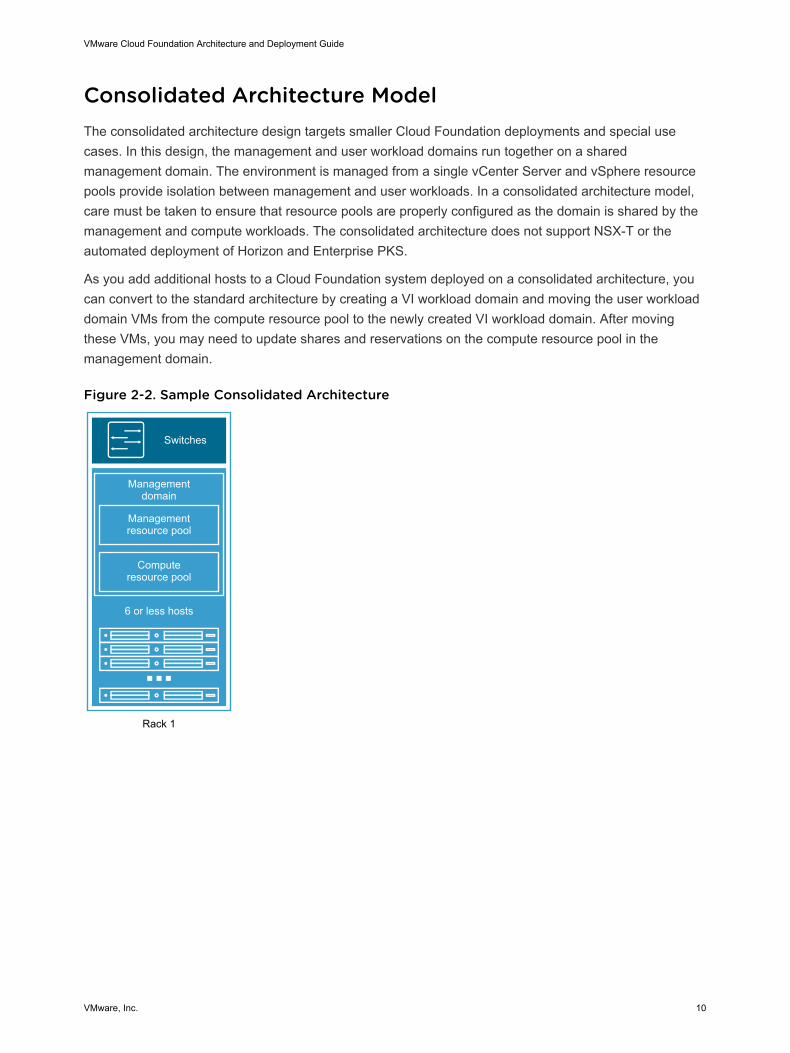
Consolidated Architecture ModelThe consolidated architecture design targets smaller Cloud Foundation deployments and special usecases. In this design, the management and user workload domains run together on a sharedmanagement domain. The environment is managed from a single vCenter Server and vSphere resourcepools provide isolation between management and user workloads. In a consolidated architecture model,care must be taken to ensure that resource pools are properly configured as the domain is shared by themanagement and compute workloads. The consolidated architecture does not support NSX-T or theautomated deployment of Horizon and Enterprise PKS.
As you add additional hosts to a Cloud Foundation system deployed on a consolidated architecture, youcan convert to the standard architecture by creating a VI workload domain and moving the user workloaddomain VMs from the compute resource pool to the newly created VI workload domain. After movingthese VMs, you may need to update shares and reservations on the compute resource pool in themanagement domain.
Figure 2-2. Sample Consolidated Architecture
Switches
6 or less hosts
Computeresource pool
Managementresource pool
Managementdomain
Rack 1
VMware Cloud Foundation Architecture and Deployment Guide
VMware, Inc. 10

Preparing your Environment forCloud Foundation 3You must prepare your environment for deploying Cloud Foundation. See the VMware Cloud FoundationPlanning and Preparation Guide.
VMware, Inc. 11
Deploying Cloud Foundation 4You begin the Cloud Foundation deployment process by deploying the Cloud Foundation Builder VM. Youthen download the deployment parameters sheet from the Cloud Foundation Builder VM. Complete thedeployment parameters spreadsheet to define your network information, host details, and other requiredinformation. This spreadsheet is then converted to a Javascript Object Notation (JSON) file and uploadedto the Cloud Foundation Builder VM. The provided information is validated, and the automated phase ofthe deployment process begins.
Prerequisites
You must prepare your environment for deploying Cloud Foundation. See the VMware Cloud FoundationPlanning and Preparation Guide.
Procedure
1 Deploy Cloud Foundation Builder VM
The Cloud Foundation Builder VM is a one-time use VM which deploys and configures themanagement domain and transfers inventory and control to SDDC Manager. During the deploymentprocess, the Cloud Foundation Builder VM validates network information you provided in thedeployment parameter spreadsheet such as DNS, network (VLANS, IPs, MTUs), and credentials.After the management domain is up and the SDDC Manager is running, the Cloud FoundationBuilder VM must be powered off and archived.
2 Download and Complete Deployment Parameter Sheet
The deployment parameter spreadsheet provides a mechanism to specify the required deploymentinformation specific to your environment. This includes information about your networks, hosts,license keys, and other information. The spreadsheet is downloaded from the Cloud FoundationBuilder VM. The completed spreadsheet is then converted to a JSON file. The deploymentparameter spreadsheet can be reused to deploy multiple Cloud Foundation instances of the sameversion.
3 Generate JSON File
The completed deployment parameter worksheet is converted to a JSON file format which is usedduring the Cloud Foundation deployment process.
4 Initiate the Cloud Foundation Bring-Up Process
During bring-up, the management domain is created on the ESXi hosts specified in the deploymentconfiguration spreadsheet. The Cloud Foundation software components are automatically deployed,configured, and licensed using the information provided.
VMware, Inc. 12
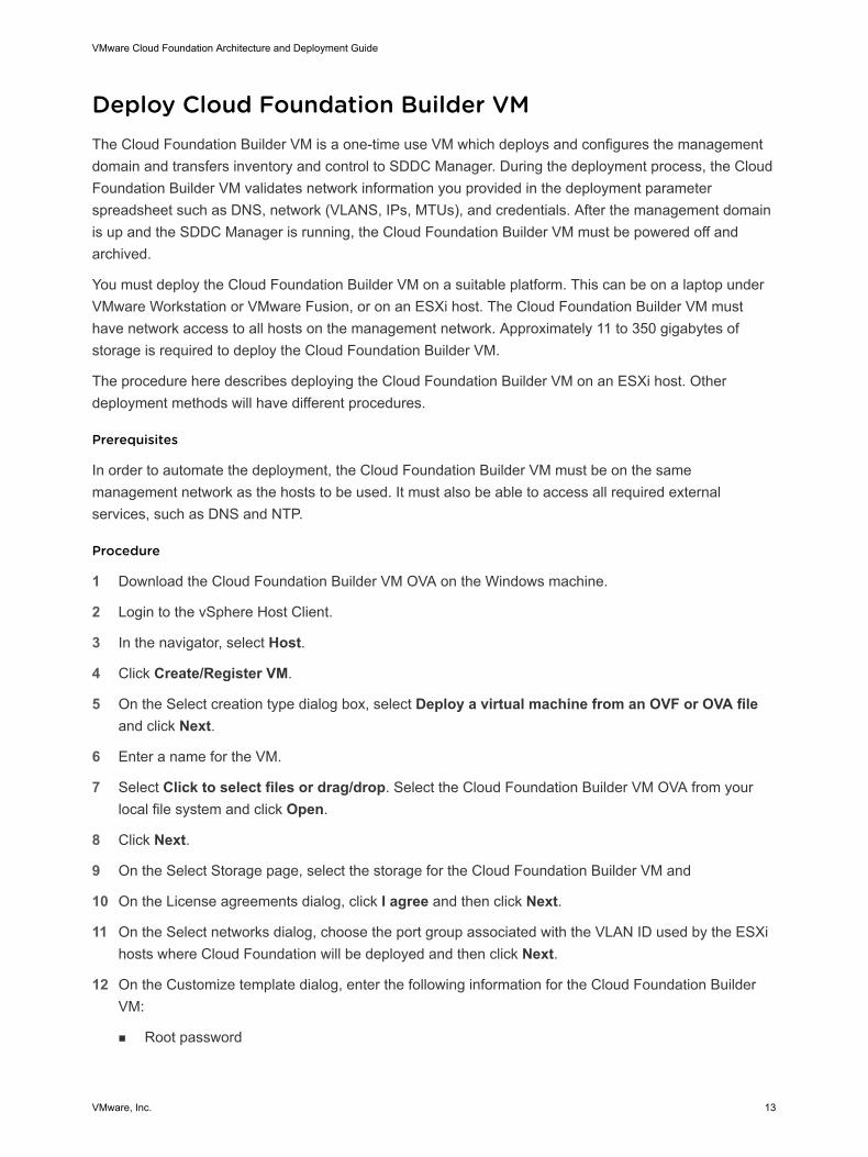
Deploy Cloud Foundation Builder VMThe Cloud Foundation Builder VM is a one-time use VM which deploys and configures the managementdomain and transfers inventory and control to SDDC Manager. During the deployment process, the CloudFoundation Builder VM validates network information you provided in the deployment parameterspreadsheet such as DNS, network (VLANS, IPs, MTUs), and credentials. After the management domainis up and the SDDC Manager is running, the Cloud Foundation Builder VM must be powered off andarchived.
You must deploy the Cloud Foundation Builder VM on a suitable platform. This can be on a laptop underVMware Workstation or VMware Fusion, or on an ESXi host. The Cloud Foundation Builder VM musthave network access to all hosts on the management network. Approximately 11 to 350 gigabytes ofstorage is required to deploy the Cloud Foundation Builder VM.
The procedure here describes deploying the Cloud Foundation Builder VM on an ESXi host. Otherdeployment methods will have different procedures.
Prerequisites
In order to automate the deployment, the Cloud Foundation Builder VM must be on the samemanagement network as the hosts to be used. It must also be able to access all required externalservices, such as DNS and NTP.
Procedure
1 Download the Cloud Foundation Builder VM OVA on the Windows machine.
2 Login to the vSphere Host Client.
3 In the navigator, select Host.
4 Click Create/Register VM.
5 On the Select creation type dialog box, select Deploy a virtual machine from an OVF or OVA fileand click Next.
6 Enter a name for the VM.
7 Select Click to select files or drag/drop. Select the Cloud Foundation Builder VM OVA from yourlocal file system and click Open.
8 Click Next.
9 On the Select Storage page, select the storage for the Cloud Foundation Builder VM and
10 On the License agreements dialog, click I agree and then click Next.
11 On the Select networks dialog, choose the port group associated with the VLAN ID used by the ESXihosts where Cloud Foundation will be deployed and then click Next.
12 On the Customize template dialog, enter the following information for the Cloud Foundation BuilderVM:
n Root password
VMware Cloud Foundation Architecture and Deployment Guide
VMware, Inc. 13
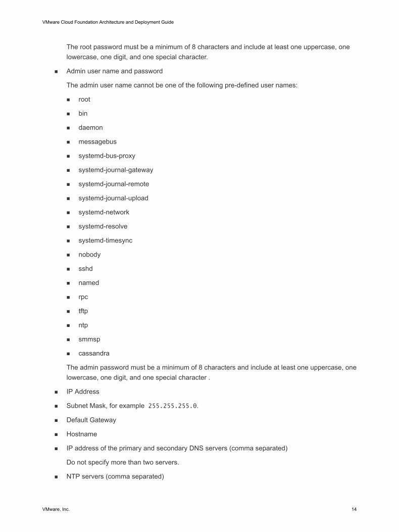
The root password must be a minimum of 8 characters and include at least one uppercase, onelowercase, one digit, and one special character.
n Admin user name and password
The admin user name cannot be one of the following pre-defined user names:
n root
n bin
n daemon
n messagebus
n systemd-bus-proxy
n systemd-journal-gateway
n systemd-journal-remote
n systemd-journal-upload
n systemd-network
n systemd-resolve
n systemd-timesync
n nobody
n sshd
n named
n rpc
n tftp
n ntp
n smmsp
n cassandra
The admin password must be a minimum of 8 characters and include at least one uppercase, onelowercase, one digit, and one special character .
n IP Address
n Subnet Mask, for example 255.255.255.0.
n Default Gateway
n Hostname
n IP address of the primary and secondary DNS servers (comma separated)
Do not specify more than two servers.
n NTP servers (comma separated)
VMware Cloud Foundation Architecture and Deployment Guide
VMware, Inc. 14

13 Review the deployment details and click Finish.
14 After the Cloud Foundation Builder VM is deployed, SSH in to the VM with the admin credentialsprovided in step 12.
15 Ensure that you can ping the ESXi hosts.
16 Verify that the Cloud Foundation Builder VM has access to the required external services, such asDNS and NTP by performing forward and reverse DNS lookups for each host and the specified NTPservers.
Download and Complete Deployment Parameter SheetThe deployment parameter spreadsheet provides a mechanism to specify the required deploymentinformation specific to your environment. This includes information about your networks, hosts, licensekeys, and other information. The spreadsheet is downloaded from the Cloud Foundation Builder VM. Thecompleted spreadsheet is then converted to a JSON file. The deployment parameter spreadsheet can bereused to deploy multiple Cloud Foundation instances of the same version.
Procedure
1 In a web browser on the Windows machine that is connected to the Cloud Foundation Builder VM,navigate to https://Cloud_Builder_VM_IP:8008.
The VMware Cloud Foundation page appears.
2 Enter the admin credentials you provided when you deployed the Cloud Foundation Builder VM andthen click Log In.
3 Confirm that your environment meets each criteria in the pre-bring-up checklist and select the checkboxes. Fix any issues before proceeding.
4 Click Next.
5 Read the End-User License Agreement and accept it. Click Next.
6 Click Download Deployment Parameter Sheet.
7 Complete the worksheet. See About the Deployment Parameter Sheet.
About the Deployment Parameter SheetThe deployment parameter Excel sheet contains tabs categorizing the information required for deployingCloud Foundation. The information provided is used to create the management domain.
The fields in yellow contain sample values that you can overwrite as appropriate. If a cell turns red, therequired information is missing, or validation has failed. All other information (including default values) arefor your reference only. Modifying any of these fields can lead to deployment errors.
Prerequisites Checklist TabThis tab is a summary of infrastructure configuration requirements that need to be satisfied beforedeploying Cloud Foundation.
VMware Cloud Foundation Architecture and Deployment Guide
VMware, Inc. 15
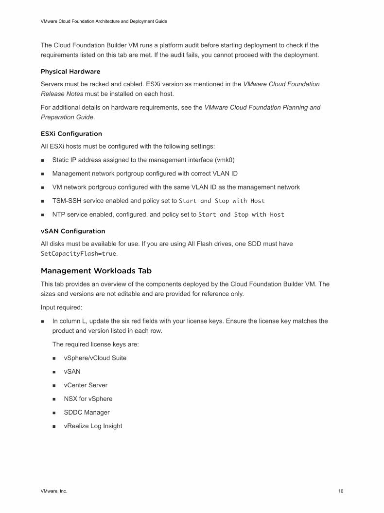
The Cloud Foundation Builder VM runs a platform audit before starting deployment to check if therequirements listed on this tab are met. If the audit fails, you cannot proceed with the deployment.
Physical Hardware
Servers must be racked and cabled. ESXi version as mentioned in the VMware Cloud FoundationRelease Notes must be installed on each host.
For additional details on hardware requirements, see the VMware Cloud Foundation Planning andPreparation Guide.
ESXi Configuration
All ESXi hosts must be configured with the following settings:
n Static IP address assigned to the management interface (vmk0)
n Management network portgroup configured with correct VLAN ID
n VM network portgroup configured with the same VLAN ID as the management network
n TSM-SSH service enabled and policy set to Start and Stop with Host
n NTP service enabled, configured, and policy set to Start and Stop with Host
vSAN Configuration
All disks must be available for use. If you are using All Flash drives, one SDD must haveSetCapacityFlash=true.
Management Workloads TabThis tab provides an overview of the components deployed by the Cloud Foundation Builder VM. Thesizes and versions are not editable and are provided for reference only.
Input required:
n In column L, update the six red fields with your license keys. Ensure the license key matches theproduct and version listed in each row.
The required license keys are:
n vSphere/vCloud Suite
n vSAN
n vCenter Server
n NSX for vSphere
n SDDC Manager
n vRealize Log Insight
VMware Cloud Foundation Architecture and Deployment Guide
VMware, Inc. 16
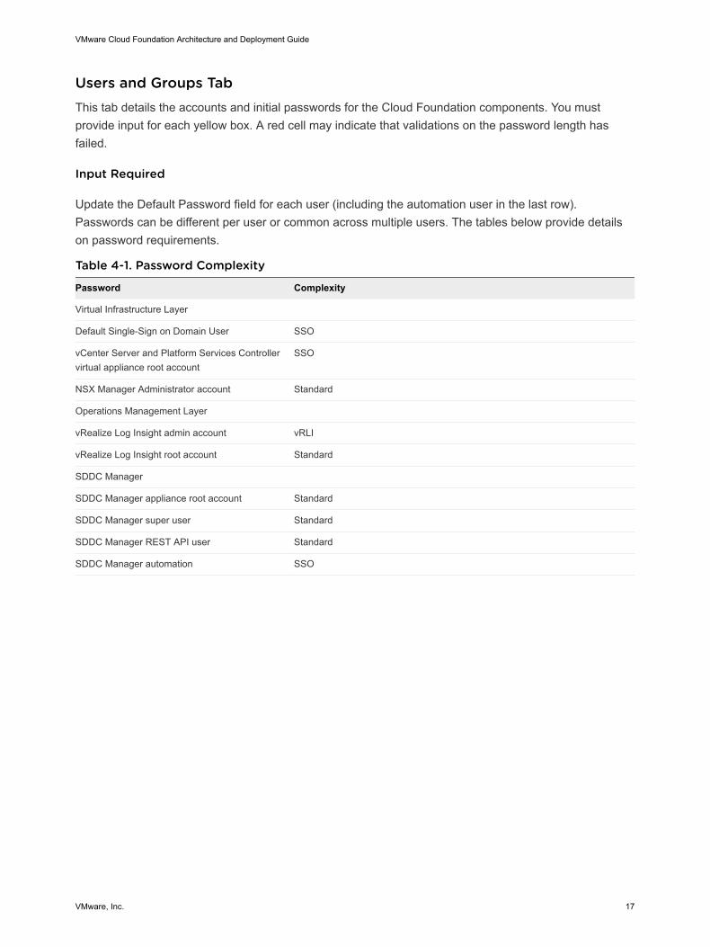
Users and Groups TabThis tab details the accounts and initial passwords for the Cloud Foundation components. You mustprovide input for each yellow box. A red cell may indicate that validations on the password length hasfailed.
Input Required
Update the Default Password field for each user (including the automation user in the last row).Passwords can be different per user or common across multiple users. The tables below provide detailson password requirements.
Table 4-1. Password Complexity
Password Complexity
Virtual Infrastructure Layer
Default Single-Sign on Domain User SSO
vCenter Server and Platform Services Controllervirtual appliance root account
SSO
NSX Manager Administrator account Standard
Operations Management Layer
vRealize Log Insight admin account vRLI
vRealize Log Insight root account Standard
SDDC Manager
SDDC Manager appliance root account Standard
SDDC Manager super user Standard
SDDC Manager REST API user Standard
SDDC Manager automation SSO
VMware Cloud Foundation Architecture and Deployment Guide
VMware, Inc. 17
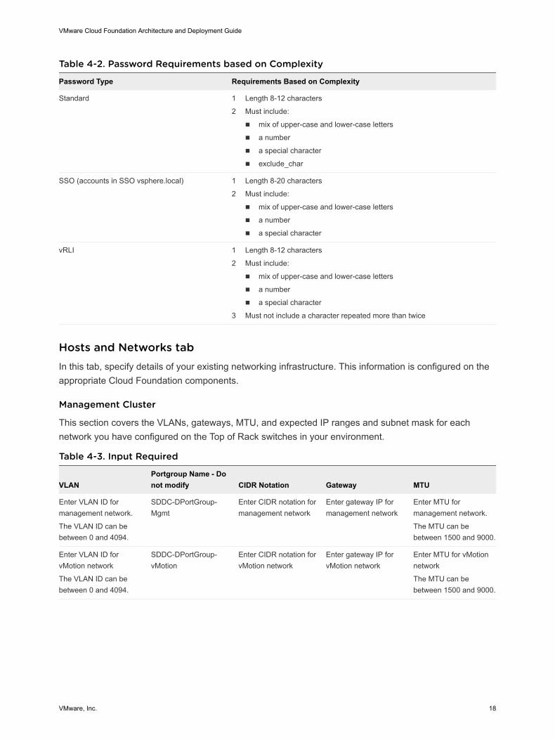
Table 4-2. Password Requirements based on Complexity
Password Type Requirements Based on Complexity
Standard 1 Length 8-12 characters
2 Must include:
n mix of upper-case and lower-case letters
n a number
n a special character
n exclude_char
SSO (accounts in SSO vsphere.local) 1 Length 8-20 characters
2 Must include:
n mix of upper-case and lower-case letters
n a number
n a special character
vRLI 1 Length 8-12 characters
2 Must include:
n mix of upper-case and lower-case letters
n a number
n a special character
3 Must not include a character repeated more than twice
Hosts and Networks tabIn this tab, specify details of your existing networking infrastructure. This information is configured on theappropriate Cloud Foundation components.
Management Cluster
This section covers the VLANs, gateways, MTU, and expected IP ranges and subnet mask for eachnetwork you have configured on the Top of Rack switches in your environment.
Table 4-3. Input Required
VLANPortgroup Name - Donot modify CIDR Notation Gateway MTU
Enter VLAN ID formanagement network.
The VLAN ID can bebetween 0 and 4094.
SDDC-DPortGroup-Mgmt
Enter CIDR notation formanagement network
Enter gateway IP formanagement network
Enter MTU formanagement network.
The MTU can bebetween 1500 and 9000.
Enter VLAN ID forvMotion network
The VLAN ID can bebetween 0 and 4094.
SDDC-DPortGroup-vMotion
Enter CIDR notation forvMotion network
Enter gateway IP forvMotion network
Enter MTU for vMotionnetwork
The MTU can bebetween 1500 and 9000.
VMware Cloud Foundation Architecture and Deployment Guide
VMware, Inc. 18
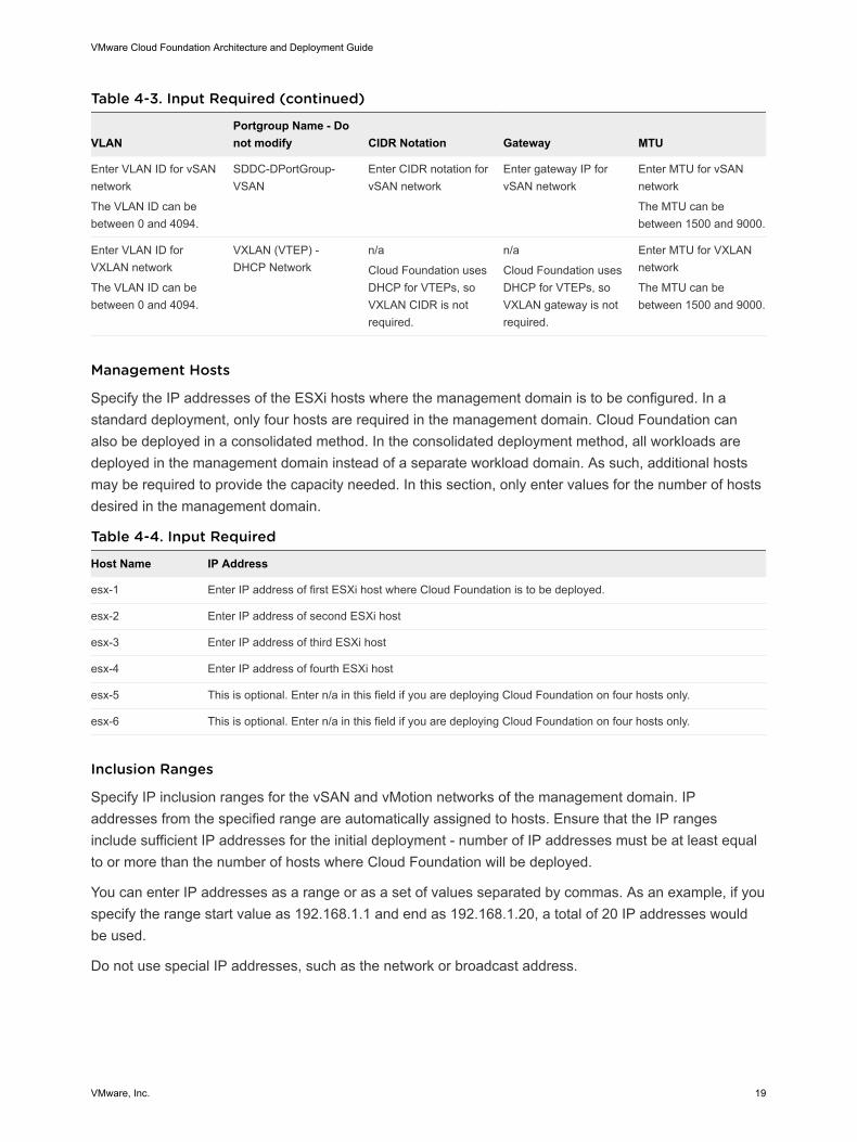
Table 4-3. Input Required (continued)
VLANPortgroup Name - Donot modify CIDR Notation Gateway MTU
Enter VLAN ID for vSANnetwork
The VLAN ID can bebetween 0 and 4094.
SDDC-DPortGroup-VSAN
Enter CIDR notation forvSAN network
Enter gateway IP forvSAN network
Enter MTU for vSANnetwork
The MTU can bebetween 1500 and 9000.
Enter VLAN ID forVXLAN network
The VLAN ID can bebetween 0 and 4094.
VXLAN (VTEP) -DHCP Network
n/a
Cloud Foundation usesDHCP for VTEPs, soVXLAN CIDR is notrequired.
n/a
Cloud Foundation usesDHCP for VTEPs, soVXLAN gateway is notrequired.
Enter MTU for VXLANnetwork
The MTU can bebetween 1500 and 9000.
Management Hosts
Specify the IP addresses of the ESXi hosts where the management domain is to be configured. In astandard deployment, only four hosts are required in the management domain. Cloud Foundation canalso be deployed in a consolidated method. In the consolidated deployment method, all workloads aredeployed in the management domain instead of a separate workload domain. As such, additional hostsmay be required to provide the capacity needed. In this section, only enter values for the number of hostsdesired in the management domain.
Table 4-4. Input Required
Host Name IP Address
esx-1 Enter IP address of first ESXi host where Cloud Foundation is to be deployed.
esx-2 Enter IP address of second ESXi host
esx-3 Enter IP address of third ESXi host
esx-4 Enter IP address of fourth ESXi host
esx-5 This is optional. Enter n/a in this field if you are deploying Cloud Foundation on four hosts only.
esx-6 This is optional. Enter n/a in this field if you are deploying Cloud Foundation on four hosts only.
Inclusion Ranges
Specify IP inclusion ranges for the vSAN and vMotion networks of the management domain. IPaddresses from the specified range are automatically assigned to hosts. Ensure that the IP rangesinclude sufficient IP addresses for the initial deployment - number of IP addresses must be at least equalto or more than the number of hosts where Cloud Foundation will be deployed.
You can enter IP addresses as a range or as a set of values separated by commas. As an example, if youspecify the range start value as 192.168.1.1 and end as 192.168.1.20, a total of 20 IP addresses wouldbe used.
Do not use special IP addresses, such as the network or broadcast address.
VMware Cloud Foundation Architecture and Deployment Guide
VMware, Inc. 19
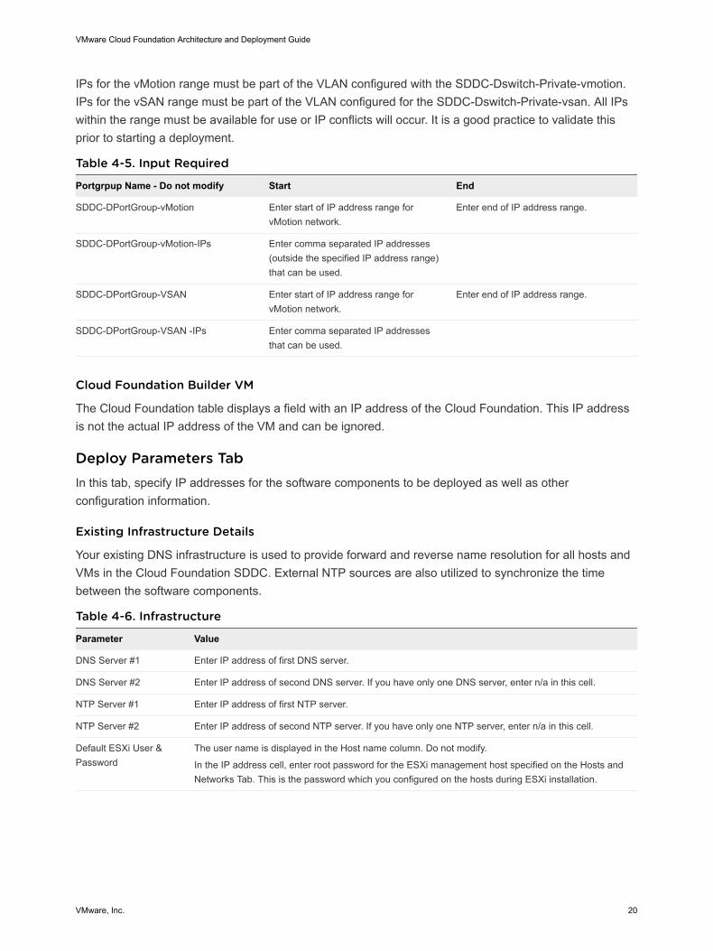
IPs for the vMotion range must be part of the VLAN configured with the SDDC-Dswitch-Private-vmotion.IPs for the vSAN range must be part of the VLAN configured for the SDDC-Dswitch-Private-vsan. All IPswithin the range must be available for use or IP conflicts will occur. It is a good practice to validate thisprior to starting a deployment.
Table 4-5. Input Required
Portgrpup Name - Do not modify Start End
SDDC-DPortGroup-vMotion Enter start of IP address range forvMotion network.
Enter end of IP address range.
SDDC-DPortGroup-vMotion-IPs Enter comma separated IP addresses(outside the specified IP address range)that can be used.
SDDC-DPortGroup-VSAN Enter start of IP address range forvMotion network.
Enter end of IP address range.
SDDC-DPortGroup-VSAN -IPs Enter comma separated IP addressesthat can be used.
Cloud Foundation Builder VM
The Cloud Foundation table displays a field with an IP address of the Cloud Foundation. This IP addressis not the actual IP address of the VM and can be ignored.
Deploy Parameters TabIn this tab, specify IP addresses for the software components to be deployed as well as otherconfiguration information.
Existing Infrastructure Details
Your existing DNS infrastructure is used to provide forward and reverse name resolution for all hosts andVMs in the Cloud Foundation SDDC. External NTP sources are also utilized to synchronize the timebetween the software components.
Table 4-6. Infrastructure
Parameter Value
DNS Server #1 Enter IP address of first DNS server.
DNS Server #2 Enter IP address of second DNS server. If you have only one DNS server, enter n/a in this cell.
NTP Server #1 Enter IP address of first NTP server.
NTP Server #2 Enter IP address of second NTP server. If you have only one NTP server, enter n/a in this cell.
Default ESXi User &Password
The user name is displayed in the Host name column. Do not modify.
In the IP address cell, enter root password for the ESXi management host specified on the Hosts andNetworks Tab. This is the password which you configured on the hosts during ESXi installation.
VMware Cloud Foundation Architecture and Deployment Guide
VMware, Inc. 20
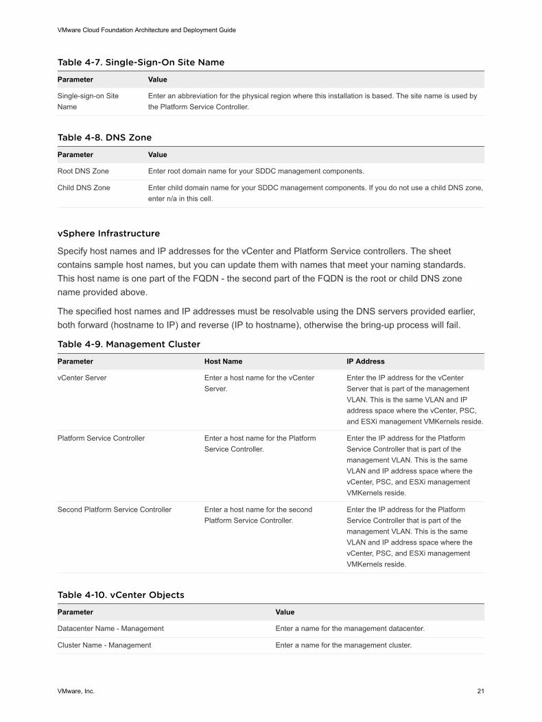
Table 4-7. Single-Sign-On Site Name
Parameter Value
Single-sign-on SiteName
Enter an abbreviation for the physical region where this installation is based. The site name is used bythe Platform Service Controller.
Table 4-8. DNS Zone
Parameter Value
Root DNS Zone Enter root domain name for your SDDC management components.
Child DNS Zone Enter child domain name for your SDDC management components. If you do not use a child DNS zone,enter n/a in this cell.
vSphere Infrastructure
Specify host names and IP addresses for the vCenter and Platform Service controllers. The sheetcontains sample host names, but you can update them with names that meet your naming standards.This host name is one part of the FQDN - the second part of the FQDN is the root or child DNS zonename provided above.
The specified host names and IP addresses must be resolvable using the DNS servers provided earlier,both forward (hostname to IP) and reverse (IP to hostname), otherwise the bring-up process will fail.
Table 4-9. Management Cluster
Parameter Host Name IP Address
vCenter Server Enter a host name for the vCenterServer.
Enter the IP address for the vCenterServer that is part of the managementVLAN. This is the same VLAN and IPaddress space where the vCenter, PSC,and ESXi management VMKernels reside.
Platform Service Controller Enter a host name for the PlatformService Controller.
Enter the IP address for the PlatformService Controller that is part of themanagement VLAN. This is the sameVLAN and IP address space where thevCenter, PSC, and ESXi managementVMKernels reside.
Second Platform Service Controller Enter a host name for the secondPlatform Service Controller.
Enter the IP address for the PlatformService Controller that is part of themanagement VLAN. This is the sameVLAN and IP address space where thevCenter, PSC, and ESXi managementVMKernels reside.
Table 4-10. vCenter Objects
Parameter Value
Datacenter Name - Management Enter a name for the management datacenter.
Cluster Name - Management Enter a name for the management cluster.
VMware Cloud Foundation Architecture and Deployment Guide
VMware, Inc. 21

Table 4-10. vCenter Objects (continued)
Parameter Value
vSphere Distributed Switch - Management Enter a name for the management vSphere distributed name.
Default vSS Portgroup Name Do not change the default value VM Network.
In the Virtual Networking - ESXi Hosts section below, the default settings are appropriate for servers withtwo physical NICs. Modify these values as appropriate if you have a different number of physical NICs.
Table 4-11. Virtual Networking - ESXi Hosts
Parameter Value
Physical NIC to Assign to vDS - Management Select the physical NIC to assign to the management vDS.
VMKernel Adaptor for Management Select the vmkernel adaptor to assign to the managementnetwork.
vSphere Standard Switch - Management Do not modify.
vmnic Allocated to vSS - Management Select the physical NIC to assign to the management vSS.
NSX
Enter IP addresses and host names for NSX installation.
Table 4-12. Management Cluster
Parameter Value
NSX Manager Enter the host name and IP address for the NSX Manager.
The host name can match your naming standards but must beregistered in DNS with both forward and reverse resolutionmatching the specified IP.
The IP address must be part of the management VLAN. This isthe same VLAN and IP address space where the vCenter, PSC,and ESXi management VMKernels reside.
NSX Controller IP Pool Start Address In IP Address, enter the starting IP address of the IP addressrange. Each IP in the range, including the starting and ending IPaddress, must be unused in your environment.
NSX Controller IP Pool End Address In IP Address, enter the end IP address of the IP address range.Each IP in the range, including the starting and ending IPaddress, must be unused in your environment.
Table 4-13. Management - Segment IDs and Multicast Ranges
Parameter Value
NSX Segment ID Range Default values for the segment ID range.
The segment ID range is used for NSX virtual wires. These arenot exposed outside of the NSX environment. Only modify thesevalues if the default range is being used in another NSXdeployment within your environment.
VMware Cloud Foundation Architecture and Deployment Guide
VMware, Inc. 22
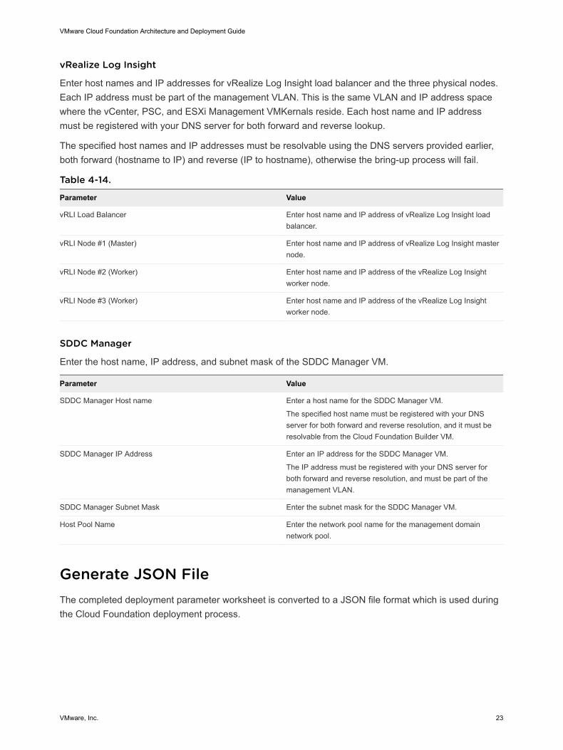
vRealize Log Insight
Enter host names and IP addresses for vRealize Log Insight load balancer and the three physical nodes.Each IP address must be part of the management VLAN. This is the same VLAN and IP address spacewhere the vCenter, PSC, and ESXi Management VMKernals reside. Each host name and IP addressmust be registered with your DNS server for both forward and reverse lookup.
The specified host names and IP addresses must be resolvable using the DNS servers provided earlier,both forward (hostname to IP) and reverse (IP to hostname), otherwise the bring-up process will fail.
Table 4-14.
Parameter Value
vRLI Load Balancer Enter host name and IP address of vRealize Log Insight loadbalancer.
vRLI Node #1 (Master) Enter host name and IP address of vRealize Log Insight masternode.
vRLI Node #2 (Worker) Enter host name and IP address of the vRealize Log Insightworker node.
vRLI Node #3 (Worker) Enter host name and IP address of the vRealize Log Insightworker node.
SDDC Manager
Enter the host name, IP address, and subnet mask of the SDDC Manager VM.
Parameter Value
SDDC Manager Host name Enter a host name for the SDDC Manager VM.
The specified host name must be registered with your DNSserver for both forward and reverse resolution, and it must beresolvable from the Cloud Foundation Builder VM.
SDDC Manager IP Address Enter an IP address for the SDDC Manager VM.
The IP address must be registered with your DNS server forboth forward and reverse resolution, and must be part of themanagement VLAN.
SDDC Manager Subnet Mask Enter the subnet mask for the SDDC Manager VM.
Host Pool Name Enter the network pool name for the management domainnetwork pool.
Generate JSON FileThe completed deployment parameter worksheet is converted to a JSON file format which is used duringthe Cloud Foundation deployment process.
VMware Cloud Foundation Architecture and Deployment Guide
VMware, Inc. 23
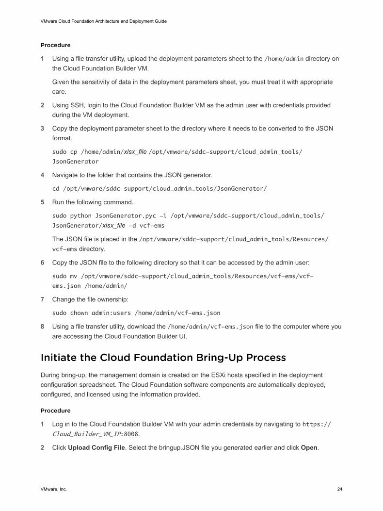
Procedure
1 Using a file transfer utility, upload the deployment parameters sheet to the /home/admin directory onthe Cloud Foundation Builder VM.
Given the sensitivity of data in the deployment parameters sheet, you must treat it with appropriatecare.
2 Using SSH, login to the Cloud Foundation Builder VM as the admin user with credentials providedduring the VM deployment.
3 Copy the deployment parameter sheet to the directory where it needs to be converted to the JSONformat.
sudo cp /home/admin/xlsx_file /opt/vmware/sddc-support/cloud_admin_tools/JsonGenerator
4 Navigate to the folder that contains the JSON generator.
cd /opt/vmware/sddc-support/cloud_admin_tools/JsonGenerator/
5 Run the following command.
sudo python JsonGenerator.pyc -i /opt/vmware/sddc-support/cloud_admin_tools/
JsonGenerator/xlsx_file -d vcf-ems
The JSON file is placed in the /opt/vmware/sddc-support/cloud_admin_tools/Resources/vcf-ems directory.
6 Copy the JSON file to the following directory so that it can be accessed by the admin user:
sudo mv /opt/vmware/sddc-support/cloud_admin_tools/Resources/vcf-ems/vcf-
ems.json /home/admin/
7 Change the file ownership:
sudo chown admin:users /home/admin/vcf-ems.json
8 Using a file transfer utility, download the /home/admin/vcf-ems.json file to the computer where youare accessing the Cloud Foundation Builder UI.
Initiate the Cloud Foundation Bring-Up ProcessDuring bring-up, the management domain is created on the ESXi hosts specified in the deploymentconfiguration spreadsheet. The Cloud Foundation software components are automatically deployed,configured, and licensed using the information provided.
Procedure
1 Log in to the Cloud Foundation Builder VM with your admin credentials by navigating to https://Cloud_Builder_VM_IP:8008.
2 Click Upload Config File. Select the bringup.JSON file you generated earlier and click Open.
VMware Cloud Foundation Architecture and Deployment Guide
VMware, Inc. 24
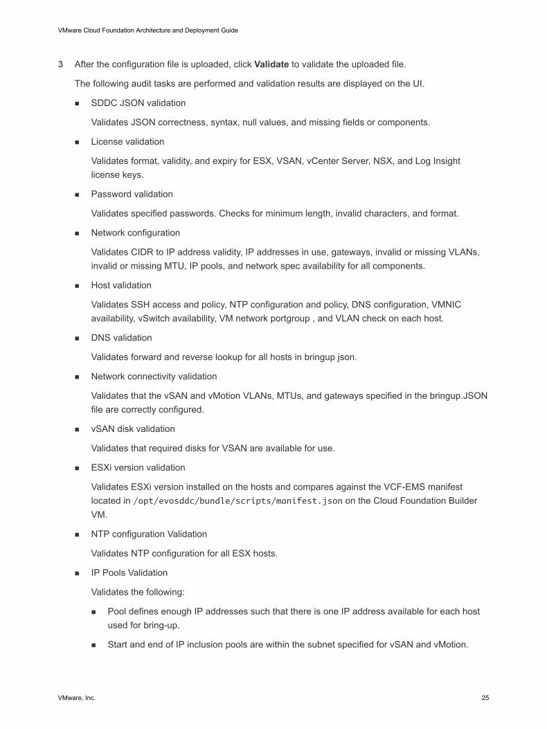
3 After the configuration file is uploaded, click Validate to validate the uploaded file.
The following audit tasks are performed and validation results are displayed on the UI.
n SDDC JSON validation
Validates JSON correctness, syntax, null values, and missing fields or components.
n License validation
Validates format, validity, and expiry for ESX, VSAN, vCenter Server, NSX, and Log Insightlicense keys.
n Password validation
Validates specified passwords. Checks for minimum length, invalid characters, and format.
n Network configuration
Validates CIDR to IP address validity, IP addresses in use, gateways, invalid or missing VLANs,invalid or missing MTU, IP pools, and network spec availability for all components.
n Host validation
Validates SSH access and policy, NTP configuration and policy, DNS configuration, VMNICavailability, vSwitch availability, VM network portgroup , and VLAN check on each host.
n DNS validation
Validates forward and reverse lookup for all hosts in bringup json.
n Network connectivity validation
Validates that the vSAN and vMotion VLANs, MTUs, and gateways specified in the bringup.JSONfile are correctly configured.
n vSAN disk validation
Validates that required disks for VSAN are available for use.
n ESXi version validation
Validates ESXi version installed on the hosts and compares against the VCF-EMS manifestlocated in /opt/evosddc/bundle/scripts/manifest.json on the Cloud Foundation BuilderVM.
n NTP configuration Validation
Validates NTP configuration for all ESX hosts.
n IP Pools Validation
Validates the following:
n Pool defines enough IP addresses such that there is one IP address available for each hostused for bring-up.
n Start and end of IP inclusion pools are within the subnet specified for vSAN and vMotion.
VMware Cloud Foundation Architecture and Deployment Guide
VMware, Inc. 25
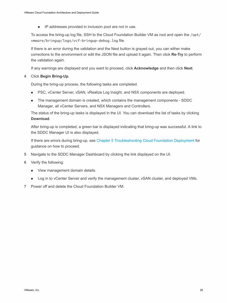
n IP addresses provided in inclusion pool are not in use.
To access the bring-up log file, SSH to the Cloud Foundation Builder VM as root and open the /opt/vmware/bringup/logs/vcf-bringup-debug.log file.
If there is an error during the validation and the Next button is grayed out, you can either makecorrections to the environment or edit the JSON file and upload it again. Then click Re-Try to performthe validation again.
If any warnings are displayed and you want to proceed, click Acknowledge and then click Next.
4 Click Begin Bring-Up.
During the bring-up process, the following tasks are completed.
n PSC, vCenter Server, vSAN, vRealize Log Insight, and NSX components are deployed.
n The management domain is created, which contains the management components - SDDCManager, all vCenter Servers, and NSX Managers and Controllers.
The status of the bring-up tasks is displayed in the UI. You can download the list of tasks by clickingDownload.
After bring-up is completed, a green bar is displayed indicating that bring-up was successful. A link tothe SDDC Manager UI is also displayed.
If there are errors during bring-up, see Chapter 5 Troubleshooting Cloud Foundation Deployment forguidance on how to proceed.
5 Navigate to the SDDC Manager Dashboard by clicking the link displayed on the UI.
6 Verify the following:
n View management domain details.
n Log in to vCenter Server and verify the management cluster, vSAN cluster, and deployed VMs.
7 Power off and delete the Cloud Foundation Builder VM.
VMware Cloud Foundation Architecture and Deployment Guide
VMware, Inc. 26
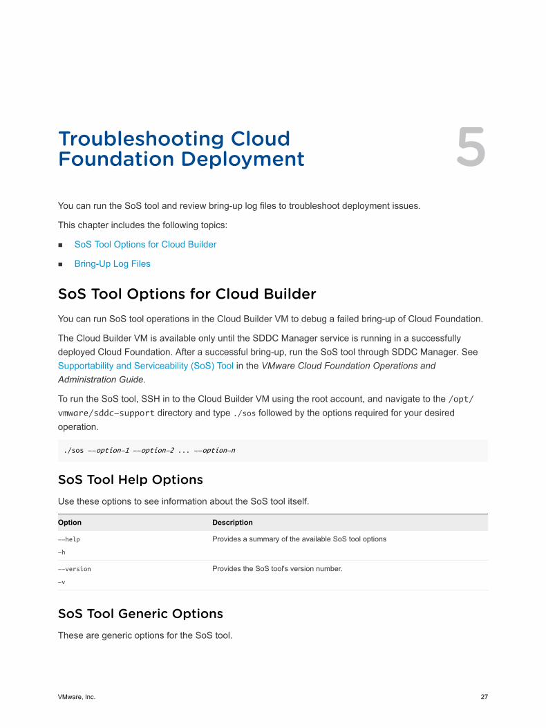
Troubleshooting CloudFoundation Deployment 5You can run the SoS tool and review bring-up log files to troubleshoot deployment issues.
This chapter includes the following topics:
n SoS Tool Options for Cloud Builder
n Bring-Up Log Files
SoS Tool Options for Cloud BuilderYou can run SoS tool operations in the Cloud Builder VM to debug a failed bring-up of Cloud Foundation.
The Cloud Builder VM is available only until the SDDC Manager service is running in a successfullydeployed Cloud Foundation. After a successful bring-up, run the SoS tool through SDDC Manager. SeeSupportability and Serviceability (SoS) Tool in the VMware Cloud Foundation Operations andAdministration Guide.
To run the SoS tool, SSH in to the Cloud Builder VM using the root account, and navigate to the /opt/vmware/sddc-support directory and type ./sos followed by the options required for your desiredoperation.
./sos --option-1 --option-2 ... --option-n
SoS Tool Help OptionsUse these options to see information about the SoS tool itself.
Option Description
--help
-h
Provides a summary of the available SoS tool options
--version
-v
Provides the SoS tool's version number.
SoS Tool Generic OptionsThese are generic options for the SoS tool.
VMware, Inc. 27

Option Description
--configure-sftp Configures SFTP for logs.
--debug-mode Runs the SoS tool in debug mode.
--force Allows SoS operations from theCloud Foundation Builder VM after bring-up.
Note It is recommended that you do not use this option.
--history Displays the last twenty SoS operations performed.
--log-dir LOGDIR Specifies the directory to store the logs.
--log-folder LOGFOLDER Specifies the name of the log directory.
--setup-json SETUP_JSON Custom setup-json file for log collection.
SoS prepares the inventory automatically based on the environment where it isrunning. If you want to collect logs for a pre-defined set of components, you cancreate a setup.json file and pass the file as input to SoS. A sample JSON file isavailable on the Cloud Builder VM in the /opt/vmware/sddc-support/ directory.
--zip Creates a zipped tar file for the output.
SoS Tool Options for JSON Generator
Option Description
--jsongenerator Invokes the JSON generator utility.
--jsongenerator-input
JSON_GENERATOR_INPUT
Specify the input file to be used by the JSON generator utility.
--jsongenerator-design
JSON_GENERATOR_DESIGN
Specify the design file for the SDDC architecture.
--jsongenerator-logs JSONGENERATORLOGS Set the directory to be used for logs. Optional.
SoS Tool Options for Platform Audit
Option Description
--platformaudit Invokes the platform audit operation.
--platformaudit-input FILE Specify the input file to be used by the platform audit utility.
--platformaudit-tree Displays a list of available audit tests.
--platformaudit-modules
MODULE1,MODULE2,MODULE3
Specify the specific audit tests to run. If specifying multiple tests, separate themodules with commas.
--platformaudit-dependency Execute audit tests with dependencies.
--platformaudit-reason Outputs reasons for failed or skipped tests.
--platformaudit-output OUTPUT Saves the output to the specified file.
SoS Tool Options for Health CheckThese SoS commands are used for checking the health status of various components or services,including connectivity, compute, and storage.
VMware Cloud Foundation Architecture and Deployment Guide
VMware, Inc. 28
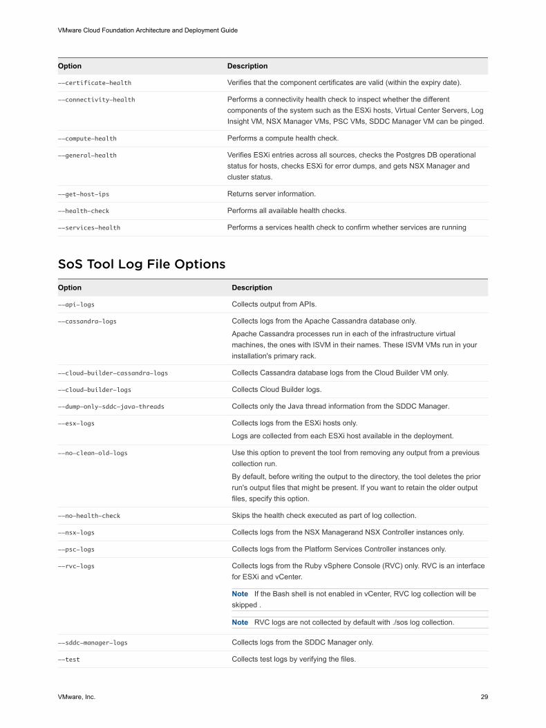
Option Description
--certificate-health Verifies that the component certificates are valid (within the expiry date).
--connectivity-health Performs a connectivity health check to inspect whether the differentcomponents of the system such as the ESXi hosts, Virtual Center Servers, LogInsight VM, NSX Manager VMs, PSC VMs, SDDC Manager VM can be pinged.
--compute-health Performs a compute health check.
--general-health Verifies ESXi entries across all sources, checks the Postgres DB operationalstatus for hosts, checks ESXi for error dumps, and gets NSX Manager andcluster status.
--get-host-ips Returns server information.
--health-check Performs all available health checks.
--services-health Performs a services health check to confirm whether services are running
SoS Tool Log File Options
Option Description
--api-logs Collects output from APIs.
--cassandra-logs Collects logs from the Apache Cassandra database only.
Apache Cassandra processes run in each of the infrastructure virtualmachines, the ones with ISVM in their names. These ISVM VMs run in yourinstallation's primary rack.
--cloud-builder-cassandra-logs Collects Cassandra database logs from the Cloud Builder VM only.
--cloud-builder-logs Collects Cloud Builder logs.
--dump-only-sddc-java-threads Collects only the Java thread information from the SDDC Manager.
--esx-logs Collects logs from the ESXi hosts only.
Logs are collected from each ESXi host available in the deployment.
--no-clean-old-logs Use this option to prevent the tool from removing any output from a previouscollection run.
By default, before writing the output to the directory, the tool deletes the priorrun's output files that might be present. If you want to retain the older outputfiles, specify this option.
--no-health-check Skips the health check executed as part of log collection.
--nsx-logs Collects logs from the NSX Managerand NSX Controller instances only.
--psc-logs Collects logs from the Platform Services Controller instances only.
--rvc-logs Collects logs from the Ruby vSphere Console (RVC) only. RVC is an interfacefor ESXi and vCenter.
Note If the Bash shell is not enabled in vCenter, RVC log collection will beskipped .
Note RVC logs are not collected by default with ./sos log collection.
--sddc-manager-logs Collects logs from the SDDC Manager only.
--test Collects test logs by verifying the files.
VMware Cloud Foundation Architecture and Deployment Guide
VMware, Inc. 29

Option Description
--vc-logs Collects logs from the vCenter Server instances only.
Logs are collected from each vCenter server available in the deployment.
--vm-screenshots Collects screen shots from all VMs.
Sample OutputThe following text is a sample output from an --ntp-health operation.
root@cloud-builder [ /opt/vmware/sddc-support ]# ./sos --ntp-health --skip-known-host --force
Welcome to Supportability and Serviceability(SoS) utility!
User passed --force flag, Running SOS from Cloud Builder VM, although Bringup is completed
and SDDC Manager is available. Please expect failures with SoS operations.
Health Check : /var/log/vmware/vcf/sddc-support/healthcheck-2018-08-24-10-49-05-7911
Health Check log : /var/log/vmware/vcf/sddc-support/healthcheck-2018-08-24-10-49-05-7911/sos.log
SDDC Manager : sddc-manager.vrack.vsphere.local
NTP : GREEN
+-----+-----------------------------------------+------------+-------+
| SL# | Area | Title | State |
+-----+-----------------------------------------+------------+-------+
| 1 | ESXi : esxi-1.vrack.vsphere.local | ESX Time | GREEN |
| 2 | ESXi : esxi-2.vrack.vsphere.local | ESX Time | GREEN |
| 3 | ESXi : esxi-3.vrack.vsphere.local | ESX Time | GREEN |
| 4 | ESXi : esxi-4.vrack.vsphere.local | ESX Time | GREEN |
| 5 | PSC : psc-1.vrack.vsphere.local | NTP Status | GREEN |
| 6 | PSC : psc-2.vrack.vsphere.local | NTP Status | GREEN |
| 7 | vCenter : vcenter-1.vrack.vsphere.local | NTP Status | GREEN |
+-----+-----------------------------------------+------------+-------+
Legend:
GREEN - No attention required, health status is NORMAL
YELLOW - May require attention, health status is WARNING
RED - Requires immediate attention, health status is CRITICAL
Health Check completed successfully for : [NTP-CHECK]
The following text is sample output from a --vm-screenshots log collection operation.
root@cloud-builder [ /opt/vmware/sddc-support ]# ./sos --vm-screenshots
--skip-known-host --force
Welcome to Supportability and Serviceability(SoS) utility!
User passed --force flag, Running SOS from Cloud Builder VM, although Bringup is completed
and SDDC Manager is available. Please expect failures with SoS operations.
Logs : /var/log/vmware/vcf/sddc-support/sos-2018-08-24-10-50-20-8013
Log file : /var/log/vmware/vcf/sddc-support/sos-2018-08-24-10-50-20-8013/sos.log
Log Collection completed successfully for : [VMS_SCREENSHOT]
VMware Cloud Foundation Architecture and Deployment Guide
VMware, Inc. 30
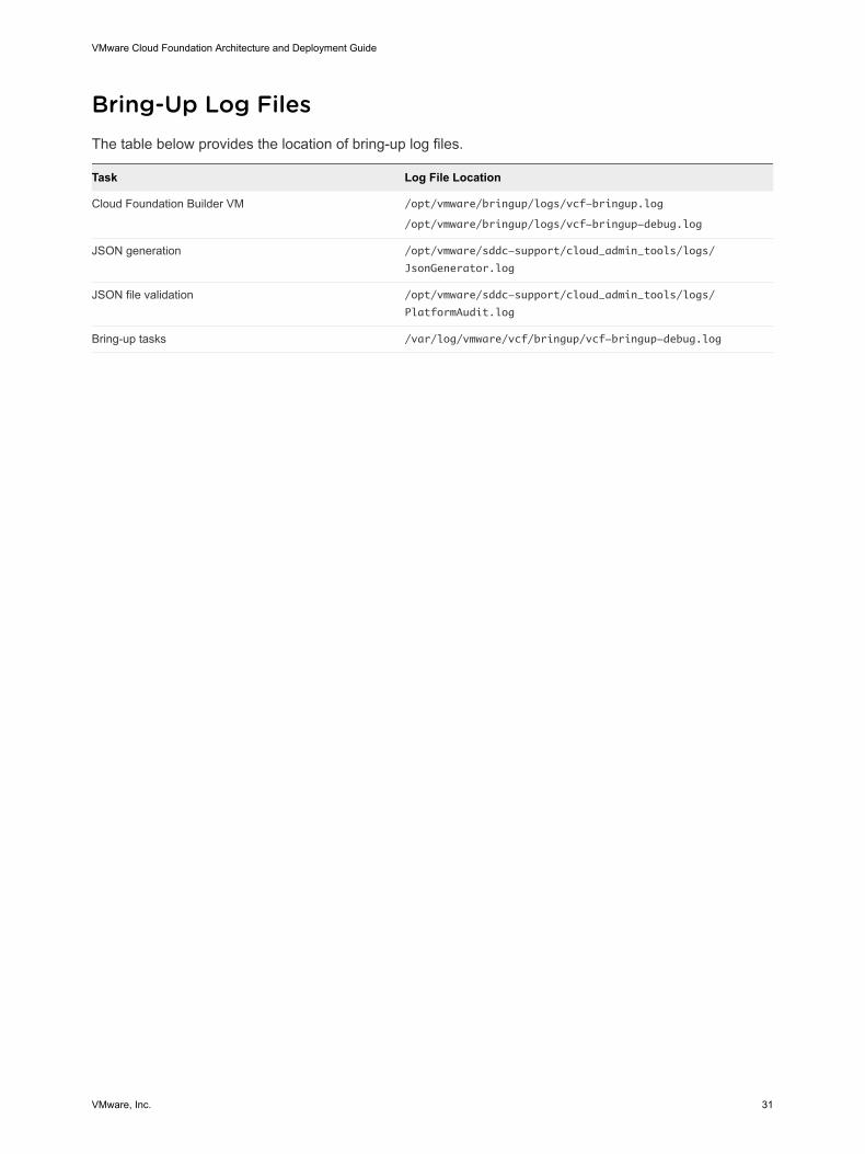
Bring-Up Log FilesThe table below provides the location of bring-up log files.
Task Log File Location
Cloud Foundation Builder VM /opt/vmware/bringup/logs/vcf-bringup.log
/opt/vmware/bringup/logs/vcf-bringup-debug.log
JSON generation /opt/vmware/sddc-support/cloud_admin_tools/logs/
JsonGenerator.log
JSON file validation /opt/vmware/sddc-support/cloud_admin_tools/logs/
PlatformAudit.log
Bring-up tasks /var/log/vmware/vcf/bringup/vcf-bringup-debug.log
VMware Cloud Foundation Architecture and Deployment Guide
VMware, Inc. 31
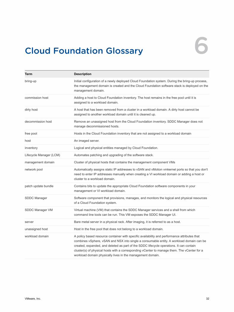
Cloud Foundation Glossary 6Term Description
bring-up Initial configuration of a newly deployed Cloud Foundation system. During the bring-up process,the management domain is created and the Cloud Foundation software stack is deployed on themanagement domain.
commission host Adding a host to Cloud Foundation inventory. The host remains in the free pool until it isassigned to a workload domain.
dirty host A host that has been removed from a cluster in a workload domain. A dirty host cannot beassigned to another workload domain until it is cleaned up.
decommission host Remove an unassigned host from the Cloud Foundation inventory. SDDC Manager does notmanage decommissioned hosts.
free pool Hosts in the Cloud Foundation inventory that are not assigned to a workload domain
host An imaged server.
inventory Logical and physical entities managed by Cloud Foundation.
Lifecycle Manager (LCM) Automates patching and upgrading of the software stack.
management domain Cluster of physical hosts that contains the management component VMs
network pool Automatically assigns static IP addresses to vSAN and vMotion vmkernel ports so that you don'tneed to enter IP addresses manually when creating a VI workload domain or adding a host orcluster to a workload domain.
patch update bundle Contains bits to update the appropriate Cloud Foundation software components in yourmanagement or VI workload domain.
SDDC Manager Software component that provisions, manages, and monitors the logical and physical resourcesof a Cloud Foundation system.
SDDC Manager VM Virtual machine (VM) that contains the SDDC Manager services and a shell from whichcommand line tools can be run. This VM exposes the SDDC Manager UI.
server Bare metal server in a physical rack. After imaging, it is referred to as a host.
unassigned host Host in the free pool that does not belong to a workload domain.
workload domain A policy based resource container with specific availability and performance attributes thatcombines vSphere, vSAN and NSX into single a consumable entity. A workload domain can becreated, expanded, and deleted as part of the SDDC lifecycle operations. It can containcluster(s) of physical hosts with a corresponding vCenter to manage them. The vCenter for aworkload domain physically lives in the management domain.
VMware, Inc. 32