Embed Size (px)
Citation preview
VMware Smart AssuranceIP Manager ConceptsGuide
VMware Smart Assurance 10.1.0

You can find the most up-to-date technical documentation on the VMware website at:
https://docs.vmware.com/
If you have comments about this documentation, submit your feedback to
VMware, Inc.3401 Hillview Ave.Palo Alto, CA 94304www.vmware.com
Copyright © 2019 VMware, Inc. All rights reserved. Copyright and trademark information.
VMware Smart Assurance IP Manager Concepts Guide
VMware, Inc. 2
Contents
1 Preface 14Purpose 14
Audience 14
VMware Smart Assurance IP Manager installation directory 14
VMware Smart Assurance IP Manager products 15
IP Manager documentation 15
Related documentation 15
Conventions used in this document 16
Typographical conventions 16
Where to get help 17
Your comments 17
2 Overview 18
3 Global Manager overview 20IC Domain Configuration objects 22
4 Configuration 23User configuration parameters 23
About commands to modify configuration parameters 24
Configuration Scanner tool 25
IP Configuration Manager 25
Assigning an IP domain manager to the IP-Configuration Manager 26
Load settings into the IP-Configuration Manager 26
Considerations when attaching to the IP-Configuration Manager 26
Push settings from the IP-Configuration Manager to IP domain managers 27
Control transfer of settings to IP domain managers 28
Edit the IP Manager's attribute, ICIM_Manager::ICIM-Manager::ServiceName, and set it to a valueother than the IP-Configuration Manager's name. This temporarily disables automatic downloadof the settings. When ready to have the IP-Configuration Manager push the settings, change theService Name attribute back to an empty value or to the IP-Configuration Manager's name. Toinitiate transfer of settings, click Push Settings.Discovery settings from the IP-ConfigurationManager to IP domain managers 29
Policy Management 29
Managed and Unmanaged IP domain managers 35
Configuration Options 35
Secure connections 36
IP versioning 36
Conventions for specifying an IPv6 address with port number 37
VMware, Inc. 3
Conventions for specifying an IPv6 address in a class instance name 38
IPv4-only features 38
Understanding interface-matching filters 39
Interface-matching filters in the tpmgr-param.conf file 41
Other interface-limiting parameter types in the tpmgr-param.conf file 41
Understanding groups and settings 42
How managed objects are assigned to groups 42
Default groups and settings 44
Matching criteria 44
Prioritized lists of groups 44
Understanding ICMP and SNMP polling 44
ICMP and SNMP polling and analysis 45
Understanding polling groups and settings 45
Polling settings for IP availability monitoring 45
Default polling groups 46
Polling setting for optimization 47
Understanding ICMP and SNMP polling and thresholds 48
ICMP and SNMP polling, thresholds, and analysis 48
Understanding threshold groups and settings 49
Understanding device access groups and settings 49
Polling settings for IP performance monitoring 49
Environment Polling setting 49
Environment Polling - External Poller 50
File System Polling setting 50
Performance Polling - Ports and Interfaces setting 50
Performance Polling - Processor and Memory setting 50
Thresholds tab 50
File Systems 51
Interface Groups 54
Port Groups - Access Ports 54
Port Groups - Trunk Ports 55
System Resource Groups 56
System VLAN Tag Groups 56
Thresholds for temperature and voltage sensors 57
Creating separate thresholds for voltage and temperature sensors 57
Threshold behavior for temperature sensors 58
Threshold settings 59
VLAN Impact Propagation Groups 59
Threshold settings for IP availability monitoring 60
Threshold settings for IP performance monitoring 60
Understanding the IP tagging feature 61
VMware Smart Assurance IP Manager Concepts Guide
VMware, Inc. 4
IP tagging scenario 63
Why modeling overlapping IP addresses is important 63
Overlapping IP addresses versus management IP addresses 64
Managed IP objects versus unmanaged IP objects 64
Automatic and user-defined IP tagging 65
IP tag naming scheme 65
Shadow IP and IPNetwork objects 68
Understanding tagging filter groups and settings 69
Audit logging 70
Raw audit log output 70
Final audit log output 71
Adapter behavior after shutdown 72
Configuring the Audit Log Adapter 72
ICMP and SNMP polling overview 73
ICMP poller 73
SNMP poller 74
Just-in-time polling 75
Request-consolidation polling 75
ICMP and SNMP polling coordination 75
Federal Information Processing Standard (FIPS) 140 76
5 Discovery 77Discovery process overview 79
Network system support 80
Fully tested devices 80
Routing-device types 81
Light discovery 81
Topology import 83
CLI device-access object import 83
ICMP, SNMP, ASNMP, and IPv6 support 84
Support for HSRP and VRRP groups 84
Support for NAS gateways 84
Support for NIC teaming 85
Support for IPSec and IKE tunnels 85
Support for overlapping IP addresses 85
Support for SNMP v3 auto discovery 85
Support for Wireless LAN 86
Wireless LAN short discovery 86
Wireless license 87
Support for Virtual Port Channel 89
Enabling vPC discovery 89
VMware Smart Assurance IP Manager Concepts Guide
VMware, Inc. 5

Viewing vPC information 90
Link Aggregation and EtherChannel discovery 90
91
Support for Virtual Data Context 91
Enabling VDC discovery 92
Viewing VDC information 92
DASL integration 92
CLI interface 93
Virtual bridging 95
Incremental reconfigure 95
Default IP route 96
Asynchronous SNMP (ASNMP) 96
Link Layer Discovery Protocol (LLDP) 97
Frame structure 97
Transmission and reception 98
Implementation 98
MIB OIDs 99
Installation impact 99
Connectivity relationship 100
Impact on discovery 100
Post-processing impact 100
Field certification and validation of connections 100
Supported devices 100
Unique VLAN naming 101
OID Info Tool 102
ESX Server Certification 102
Attributes for ESX Host 102
Supported ESX versions 103
Pre-requisites 103
Supported functionality 103
Unsupported functionality 104
Cisco Nexus 1000V implementation 105
105
Cisco Nexus 1000v certification 105
Relationship between Nexus 1000v, VMs and ESX server 105
Autodiscovery of VMs connected to the Cisco Nexus 1000V 106
Attributes for Cisco Nexus 1000v 106
Events and Exceptions 106
Viewing Nexus vSwitch consolidated map 106
Cisco Unified Computing System Certification 108
Supported features 110
VMware Smart Assurance IP Manager Concepts Guide
VMware, Inc. 6
Managing Virtual Machines present on Blade Server of UCS 111
Discovery and monitoring 111
Relationships 112
Attributes and events 113
Discovery and monitoring 113
Cisco UCS performance monitoring 113
Faults and Exceptions 114
Fabric Interconnect performance monitoring 114
UCS Map 116
Viewing maps 116
Root cause analysis for external switch Down 119
AggregateLink representation in the Map console 119
Discovery and the VPN-Tagging Server 121
About seed files 121
Seed file template 122
Seed file dual use 122
Seed file format 122
Seed-entry system identifiers 122
Notation and syntax 123
Specifying a port 123
Specifying a community string 123
Mandatory keyword options for SNMPv1 or v2c 124
Mandatory keyword options for SNMPv3 124
Seed file examples 124
Seed file example for v1/v2c candidate systems 124
Seed file example for v3 candidate systems 125
Which systems to put in a seed file 126
Seed file sources 126
Autodiscovery seed systems 127
SNMPv3 systems 127
Multiple seed entries for multiple IP-address systems 127
Discovery methods 127
Manual discovery 128
Autodiscovery 128
Discovery phases 129
Phase 1: Perform initial polling of the candidate system 130
Phase 2: Determine the destination of the candidate system 132
Phase 3: Probe the system added to the topology 134
Phase 4: Post-process the discovery information 146
Autodiscovery data sources 148
Topology MIBs data source 148
VMware Smart Assurance IP Manager Concepts Guide
VMware, Inc. 7

IP address table MIB data source 149
ARP table MIB data source 149
Discovery of NIC teaming 149
NIC teaming 149
Discovery MIBs 150
Vendor support 151
Redundancy group creation 151
Discovery and short discovery of IPSec tunnels 151
Monitoring IPSec tunnels 151
Rediscovering IPSec tunnels 152
Analyzing IPSec tunnels 154
Discovery and the local name resolution service 155
SM_IP_VERSIONS environment variable 155
DiscoveryAddrPref parameter 155
Hostname resolution and IP address checking 156
How discovery names a system 156
TM_USEAUTONAME option for automatic name resolution 157
TM_USESEEDNAME option for seed-file name resolution 157
Configuring automatic name resolution 157
Preparing for manual discovery 158
Select autodiscovery data sources 159
Initiating manual or autodiscovery 160
Using the Add Agent command to initiate discovery 160
Stopping autodiscovery 161
Initiating postprocessing 161
About discovery filters 161
Inclusive-type filtering 162
Manual accept mode and system limit 162
IPv4 and SNMPv1/v2c support 162
Discovery filter fields 162
Core fields 163
Extended options 163
Discovery filter considerations 165
Discovery filter matching 165
First-level filter matching 166
Second-level filter matching 166
Examples of discovery filters 167
Filtering a range of IP addresses 167
Filtering by system type, name, and description 167
Filtering with manual accept mode 168
Filtering by system OID 168
VMware Smart Assurance IP Manager Concepts Guide
VMware, Inc. 8
Discovery results 169
Successful discovery 169
Unsuccessful discovery 169
Unsuccessful rediscovery 169
Discovery error scenarios and results 169
Discovery errors 171
System hostname does not resolve to an IP address 171
UNIX name resolution sources 171
SNMP agent violates SNMP protocol 172
System does not support SNMP 172
Incorrect read community string 173
Insufficient number of volume licenses 173
DiscoveryError notifications 174
SNMP request times out 174
SNMP agent loops 175
System Down 176
Qualified access address not found 176
System previously discovered fails authentication 176
Pending Devices list 176
Information provided by the Pending Devices list 178
Managing systems on the Pending Devices list 179
Fine-tuning parameter settings in discovery.conf 179
About certifying managed devices 180
Syntax of device entries in oid2type_Field.conf 180
Device entry examples 181
Device entry field descriptions 182
Device entries for oid2type_Field.conf 183
Submit certification request to VMware 183
Discovery hook scripts 184
When discovery hook scripts run 184
How discovery hook scripts identify systems for processing 184
Discovery hook scripts and ICMPSNMP and ICMPONLY systems 184
Automatic and manual discovery 185
Discovery methods 185
Full discovery 185
Pending discovery 186
Discovery considerations 186
Scheduling automatic discovery 186
Read community strings 187
About managing and unmanaging topology objects 187
Types of objects that can be managed or unmanaged 187
VMware Smart Assurance IP Manager Concepts Guide
VMware, Inc. 9
Rules that govern manage and unmanage operations 188
Methods to control the management state of objects 189
Persistent management state 189
Incremental reconfigure 190
Handling duplicate IP address errors 190
How to prevent a duplicate IP address error 191
Redundancy groups 191
HSRP groups 192
VRRP groups 192
ICMP 192
ICMP IP version support 192
ICMP operation 193
SNMP 193
SNMP key components 193
SNMP basic operations 194
SNMP versions 194
SNMP version support 195
SNMP IP version support 196
About ICMP and SNMP polling parameters 196
6 Availability Manager 197Network notifications 197
Viewing network notifications 197
Network topology 198
Network topology in maps 201
Network topology map pop-up menus 201
Network topology map graphical representations 201
Network topology map types 201
Physical Connectivity map 202
IP Network Connectivity map 203
IP Network Membership map 203
VLAN Connectivity map 203
VLAN Membership map 203
Group maps 204
Network containment 204
Opening a network containment dialog box 204
Root-cause problems, exceptions, and events 205
Trap analysis 205
Thresholds associated with unstable analysis 206
Example of unstable analysis 206
Unstable notifications for backup or dial-on-demand interfaces 207
VMware Smart Assurance IP Manager Concepts Guide
VMware, Inc. 10
Redundancy groups 208
Card redundancy groups 209
System redundancy groups 209
Network adapter redundancy groups 210
NIC teaming functionality 211
HSRPGroups 213
VRRP Groups 213
7 Performance Manager and Server Performance Manager 215About IP Performance Manager 215
Performance monitoring 215
Performance analysis 216
Performance notifications 216
Before you start 217
SNMP traps processed 217
SNMP traps processed for discovery 218
SNMP traps processed for analysis 218
DisplayName and Name attributes 218
Naming convention for network objects 218
8 NAS 219Introduction to network-attached storage 219
Overview of the IP Availability Manager Extension for NAS 219
VMware Celerra devices 220
NetApp Filer 222
The VMware Smart Assurance IP NAS solution 222
Monitoring 223
Analysis 223
Notifications 223
Impacts 224
NAS IP discovery 224
ICMP and SNMP probes 224
HTTPS/XML discovery probe 224
Discovery in the domain manager 224
NAS post processing 225
Celerra devices for NAS Extension functionality 225
Control Station and Data Mover IP addresses 225
Control Station usernames and passwords 226
Scenarios 226
Scenario 1: External IP network cable linking to NAS device fails 226
Scenario 2: Connectivity loss on the Control Station external interface 227
VMware Smart Assurance IP Manager Concepts Guide
VMware, Inc. 11
Scenario 3: Network Server fails due to a power supply failure 228
NAS notifications 229
NAS topology map 229
NAS device topology map graphical representations 229
NAS device map types 230
NAS containment 233
9 Terminology 234System and device 235
Modeled topology 235
Object 236
Domain Manager 236
Satellite Domain Manager 236
Device connection 237
Discovery 237
Map Console 238
NASChassis Element 238
Edge (Map Console display component) 238
IP Availability Manager 238
IP Performance Manager 239
Event 239
Icon (Map Console display component) 239
IP Manager 239
Global Manager 239
Notification 240
Notification Log 240
Repository 240
Global Console 240
Impact Analysis 240
Logical link 240
Partition 241
Managed Element 241
Root-Cause Analysis 241
Topology Browser 242
Adapter 242
FileServer Element 242
Certification 242
Certification Matrix 242
Codebook 242
Correlation Model 242
Correlator 243
VMware Smart Assurance IP Manager Concepts Guide
VMware, Inc. 12

Broker 243
Containment 243
ICMP 243
ICMP operation 244
SNMP 244
SNMP key components 244
SNMP basic operations 244
SNMP versions 245
SNMPv1, SNMPv2c, and SNMPv3 security 245
NASChassis 245
FileServer 246
Comparable terms 246
Wildcard patterns 247
VMware Smart Assurance IP Manager Concepts Guide
VMware, Inc. 13
Preface 1As part of an effort to improve its product lines, VMware periodically releases revisions of its software andhardware. Therefore, some functions described in this document might not be supported by all versions ofthe software or hardware currently in use. The product release notes provide the most up-to-dateinformation on product features.
Contact your VMware technical support professional if a product does not function properly or does notfunction as described in this document.
Note This document was accurate at publication time. Go to VMware Support (docs.vmware.com)
This chapter includes the following topics:
n Purpose
n Audience
n VMware Smart Assurance IP Manager installation directory
n VMware Smart Assurance IP Manager products
n IP Manager documentation
n Related documentation
n Conventions used in this document
n Where to get help
n Your comments
Purpose
This document is part of the VMware Smart Assurance IP Manager documentation set. It providesconceptual information on IP Manager products.
Audience
This document is intended for IT managers and system administrators.
VMware Smart Assurance IP Manager installationdirectory
VMware, Inc. 14
In this document, the term BASEDIR represents the location where VMware Smart Assurance software isinstalled.
n For UNIX, this location is: /opt/InCharge/<productsuite>.
On UNIX operating systems, IP Manager is, by default, installed to: /opt/InCharge/IP/smarts. Thislocation is referred to as BASEDIR/smarts.
Optionally, you can specify the root of BASEDIR to be something different, but you cannot change the<productsuite> location under the root directory.
The VMware Smart Assurance System Administration Guide provides more information about thedirectory structure of VMware Smart Assurance software.
VMware Smart Assurance IP Manager products
The VMware Smart Assurance IP Manager includes the following products:
n VMware Smart Assurance IP Availability Manager
n VMware Smart Assurance IP Performance Manager
n VMware Smart Assurance IP Availability Manager Extension for NAS
IP Manager documentation
The following documents are relevant to users of the IP Manager product. Electronic versions of theupdated manuals are available at VMware Online Support: docs.vmware.com
n VMware Smart Assurance IP Manager Release Notes
n VMware Smart Assurance Open Source License and Copyright Information
n VMware Smart Assurance Installation Guide for SAM, IP, ESM, MPLS, and NPM Managers
n VMware Smart Assurance IP Manager Deployment Guide
n VMware Smart Assurance IP Manager Concepts Guide
n VMware Smart Assurance IP Manager User Guide
n VMware Smart Assurance IP Manager Reference Guide
n VMware Smart Assurance Topology Split Manager User Guide
n VMware Smart Assurance IP Manager Troubleshooting Guide
n VMware Important Notice
n VMware Smart Assurance IP Manager Certification Matrix
Related documentation
VMware Smart Assurance IP Manager Concepts Guide
VMware, Inc. 15
The following VMware Smart Assurance publications provide additional information:
n VMware Smart Assurance System Administration Guide
n VMware Smart Assurance Common Information Model (ICIM) 1.11 Reference for Non-ServiceAssurance Manager Products
n VMware Smart Assurance Common Information Model (ICIM) Reference for Service AssuranceManager
n Smarts Foundation EMC Data Access API (EDAA) Programmer Guide
n VMware Smart Assurance ASL Reference Guide
n VMware Smart Assurance Perl Reference Guide
n VMware Smart Assurance MODEL Reference Guide
n VMware Smart Assurance Dynamic Modeling Tutorial
Conventions used in this document
VMware uses the following conventions for special notices:
Note NOTICE is used to address practices not related to personal injury.
A note presents information that is important, but not hazard-related.
An important notice contains information essential to software or hardware operation.
Typographical conventions
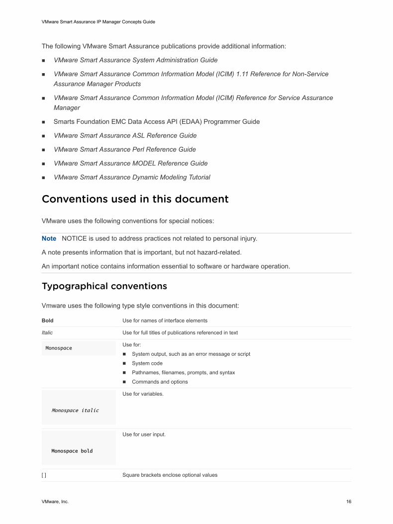
Vmware uses the following type style conventions in this document:
Bold Use for names of interface elements
Italic Use for full titles of publications referenced in text
MonospaceUse for:
n System output, such as an error message or script
n System code
n Pathnames, filenames, prompts, and syntax
n Commands and options
Monospace italic
Use for variables.
Monospace bold
Use for user input.
[ ] Square brackets enclose optional values
VMware Smart Assurance IP Manager Concepts Guide
VMware, Inc. 16
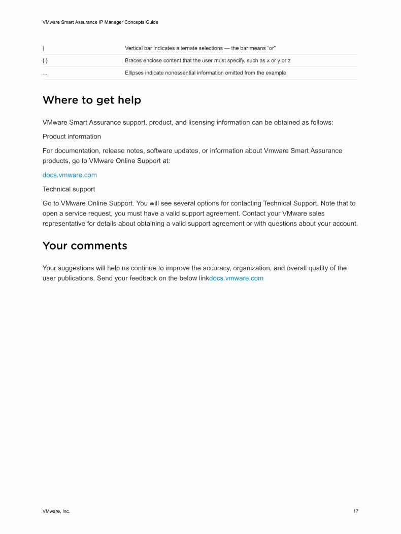
| Vertical bar indicates alternate selections — the bar means “or”
{ } Braces enclose content that the user must specify, such as x or y or z
... Ellipses indicate nonessential information omitted from the example
Where to get help
VMware Smart Assurance support, product, and licensing information can be obtained as follows:
Product information
For documentation, release notes, software updates, or information about Vmware Smart Assuranceproducts, go to VMware Online Support at:
docs.vmware.com
Technical support
Go to VMware Online Support. You will see several options for contacting Technical Support. Note that toopen a service request, you must have a valid support agreement. Contact your VMware salesrepresentative for details about obtaining a valid support agreement or with questions about your account.
Your comments
Your suggestions will help us continue to improve the accuracy, organization, and overall quality of theuser publications. Send your feedback on the below linkdocs.vmware.com
VMware Smart Assurance IP Manager Concepts Guide
VMware, Inc. 17
Overview 2IP networks are comprised of thousands of interconnected devices. Any outage can cause a flood ofalarms on the console, leaving operators with the task of trying to distinguish root-cause problems fromtheir symptoms. To provide the actionable information needed to sustain service, management solutionsmust automate the following functions:
n Discovery - Determine what elements exist in the environment.
n Modeling - Combine the results of discovery with data from other sources to map where the elementsare located, how they are related, and how each element’s behavior correlates with related elements.
n Root-cause and impact analysis - Provide the actionable intelligence necessary to sustain service byrevealing what precisely are the problems that need to be fixed and what is the impact of theseproblems on the business.
Most management solutions today are event-based and rely on rules to provide intelligence for a setof events that occurs. Rules writing means that for every possible event or combination of events thatmight occur in a complex distributed network, you need to create a rule that accounts for thatcondition. The problems with this approach are obvious—there’s no built-in analysis, the solutioncan’t scale with the constant change so characteristic of today’s networks, and it’s very expensive,time consuming and labor intensive, because the rules-writing never ends.
VMware Smart Assurance takes a different approach since it relies on two key technologies:
n The VMware Smart Assurance Common Information Model
n The patented Codebook Correlation Technology
The VMware Smart Assurance Common Information Model is based on the DMTF standard and isextended to include many classes and relationships. It is a conceptual and structural view of systemsthat applies object-oriented concepts to systems management. It provides a unified representationand classification of logical and physical entities that describes their state, behavior and relationships.
The model uses generic objects, such as Switch, Host, Application or Service Offering, to representIT infrastructure devices and their authentic problems. The model is basically a library of genericphysical and logical objects that includes attributes, relationships it can participate in with otherobjects, authentic problems, characteristic symptoms of problems it can cause, and how the problemspropagate to related objects. These generic objects represent a wealth of knowledge about that typeof object and its behavior. By associating business objects, such as services and customers, withapplications at the edge of the network, VMware Smart Assurance can automatically correlate ITproblems to business impacts.
VMware, Inc. 18
Object and relationship instances discovered in the environment are instantiated with the library ofgeneric objects to automatically become part of a real-time inventory of, or repository for, themanaged environment.
The Codebook is layered over the model to monitor the environment, look for combinations ofsymptoms that indicate service-affecting problems, and deliver the actionable intelligence needed toprioritize corrective action on the problems that matter most. Problem signatures, which are a set ofsymptoms that create a unique identifier for a problem, are derived from the library and repository.These signatures are stored in the Codebook.
VMware Smart Assurance IP Manager provides powerful discovery, modeling, root-cause, and impactanalysis capabilities across the IP network, including network-attached storage. The product suite isdistributed on a CD/DVD-ROM and available for download from vmware online support. It is installed,by default, to the /IP subdirectory under the InCharge root directory. The VMware Smart AssuranceInstallation Guide for SAM, IP, ESM, MPLS, and NPM Managers provides the procedure to installservices manually for the underlying servers used in the IP Management Suite.
VMware Smart Assurance IP Manager represents the following VMware Smart Assurance DomainManagers:
n VMware Smart Assurance IP Availability Manager
n VMware Smart Assurance IP Performance Manager
n VMware Smart Assurance IP Server Performance Manager
n VMware Smart Assurance IP Availability Manager Extension for NAS
n VMware Smart Assurance IP Configuration Manager
A Domain Manager is a service assurance application that is associated with a particular type ofinformation technology domain, such as networks, systems, applications, or application services. ForIP Manager, the domain is IP network transport. Each Domain Manager is autonomous in the sensethat it:
n Maintains its own data models, repository, and problem signatures.
n Monitors and analyzes the discovered objects in its own domain.
The IP Availability Manager and IP Performance Manager are examples of VMware Smart AssuranceDomain Managers. You can choose to start IP Availability Manager (AM) only, IP PerformanceManager (PM) only or a combination of both IP Availability Manager and IP Performance Manager(AM-PM). The configurations and licenses that are applied to an IP Manager at startup determinewhich discovery and analysis will run.
VMware Smart Assurance IP Manager Concepts Guide
VMware, Inc. 19
Global Manager overview 3The Global Manager is part of the VMware Smart Assurance Service Assurance Manager. Most of theconfiguration tasks for setting up the Global Manager in an IP Manager deployment are accomplished byusing the Global Manager Administration Console view of the Global Console. Global ManagerAdministration Console interaction with the Global Manager summarizes the Global ManagerAdministration Console interaction with the Global Manager.
VMware, Inc. 20
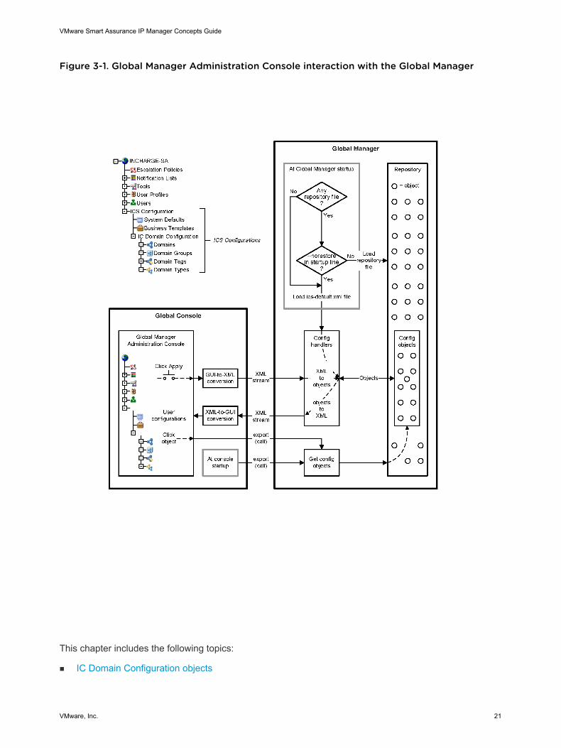
Figure 3-1. Global Manager Administration Console interaction with the Global Manager
This chapter includes the following topics:
n IC Domain Configuration objects
VMware Smart Assurance IP Manager Concepts Guide
VMware, Inc. 21
IC Domain Configuration objects
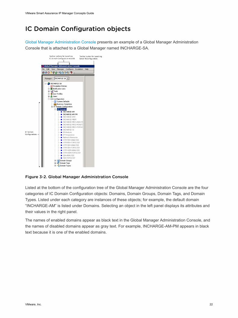
Global Manager Administration Console presents an example of a Global Manager AdministrationConsole that is attached to a Global Manager named INCHARGE-SA.
Figure 3-2. Global Manager Administration Console
Listed at the bottom of the configuration tree of the Global Manager Administration Console are the fourcategories of IC Domain Configuration objects: Domains, Domain Groups, Domain Tags, and DomainTypes. Listed under each category are instances of these objects; for example, the default domain“INCHARGE-AM” is listed under Domains. Selecting an object in the left panel displays its attributes andtheir values in the right panel.
The names of enabled domains appear as black text in the Global Manager Administration Console, andthe names of disabled domains appear as gray text. For example, INCHARGE-AM-PM appears in blacktext because it is one of the enabled domains.
VMware Smart Assurance IP Manager Concepts Guide
VMware, Inc. 22
Configuration 4This chapter includes the following topics:
n User configuration parameters
n Configuration Scanner tool
n IP Configuration Manager
n Conventions for specifying an IPv6 address with port number
n Conventions for specifying an IPv6 address in a class instance name
n IPv4-only features
n Understanding interface-matching filters
n Understanding groups and settings
n Understanding ICMP and SNMP polling
n Understanding polling groups and settings
n Default polling groups
n Understanding ICMP and SNMP polling and thresholds
n Understanding threshold groups and settings
n Understanding device access groups and settings
n Polling settings for IP performance monitoring
n Thresholds tab
n Threshold settings for IP availability monitoring
n Threshold settings for IP performance monitoring
n Understanding the IP tagging feature
n Understanding tagging filter groups and settings
n Audit logging
n ICMP and SNMP polling overview
n Federal Information Processing Standard (FIPS) 140
User configuration parameters
VMware, Inc. 23
As with most VMware Smart Assurance configuration files, the user configuration files for the IP Managerare used to set attributes for certain objects within a server’s environment when the server starts up. Theparameters and their values in a configuration file become the attributes and their values for the createdobjects.
For the discovery.conf file, as an example, the associated object is an instance of theICF_TopologyManager class and is named ICF-TopologyManager.
The VMware Smart Assurance IP Manager User Guide provides information on how to modify userconfiguration parameters.
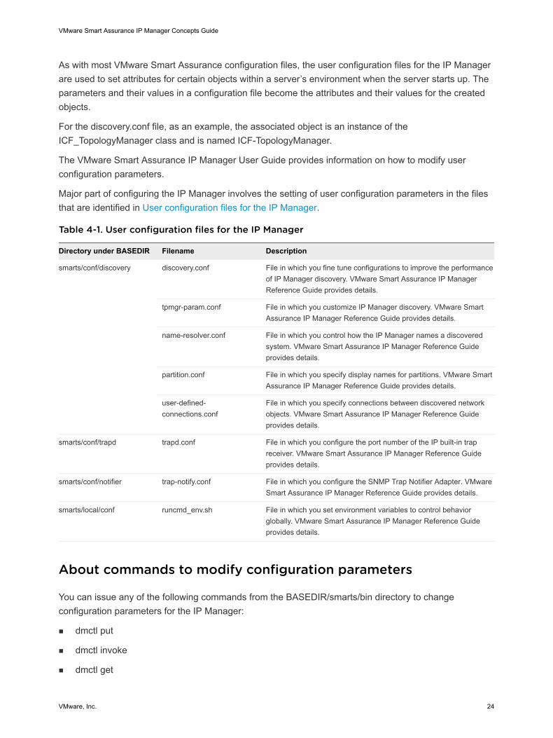
Major part of configuring the IP Manager involves the setting of user configuration parameters in the filesthat are identified in User configuration files for the IP Manager.
Table 4-1. User configuration files for the IP Manager
Directory under BASEDIR Filename Description
smarts/conf/discovery discovery.conf File in which you fine tune configurations to improve the performanceof IP Manager discovery. VMware Smart Assurance IP ManagerReference Guide provides details.
tpmgr-param.conf File in which you customize IP Manager discovery. VMware SmartAssurance IP Manager Reference Guide provides details.
name-resolver.conf File in which you control how the IP Manager names a discoveredsystem. VMware Smart Assurance IP Manager Reference Guideprovides details.
partition.conf File in which you specify display names for partitions. VMware SmartAssurance IP Manager Reference Guide provides details.
user-defined-connections.conf
File in which you specify connections between discovered networkobjects. VMware Smart Assurance IP Manager Reference Guideprovides details.
smarts/conf/trapd trapd.conf File in which you configure the port number of the IP built-in trapreceiver. VMware Smart Assurance IP Manager Reference Guideprovides details.
smarts/conf/notifier trap-notify.conf File in which you configure the SNMP Trap Notifier Adapter. VMwareSmart Assurance IP Manager Reference Guide provides details.
smarts/local/conf runcmd_env.sh File in which you set environment variables to control behaviorglobally. VMware Smart Assurance IP Manager Reference Guideprovides details.
About commands to modify configuration parameters
You can issue any of the following commands from the BASEDIR/smarts/bin directory to changeconfiguration parameters for the IP Manager:
n dmctl put
n dmctl invoke
n dmctl get
VMware Smart Assurance IP Manager Concepts Guide
VMware, Inc. 24
n sm_tpmgr
The dmctl utility is described in the HTML pages that are located in the BASEDIR/smarts/doc/html/usage directory of any Domain Manager installation area. The VMware Smart Assurance IP ManagerReference Guide provides additional syntax information and also the parameters to enable andcontrol the ConfigChange event.
Configuration Scanner tool
The Configuration Scanner tool scans for configuration changes in your current installation. It scans forcustomizations with regard to the following:
n Polling and threshold settings: The tool presents the non-default values and settings, that is, thetool generates a list of polling settings and threshold parameters that have changed from their defaultvalues, along with details of all the groups they are associated with. The output also includes taggingsettings. In case of CLI settings, the tool collects and displays the username and the associatedmatching criteria.
n Configuration files: The tool generates a list of files that have changed from the default installation.The tool scans the files in the SM_SITEMOD and base installation and does a two-way differenceanalysis to figure out what files have changed, and displays the list of files, flagged appropriately asmodified or added. For discovery.conf, name-resolver.conf, and tpmgr-param.conf files, the toolparses through the content and presents the difference at an attribute->value pair level. TheclientConnect.conf, serverConnect.conf, brokerConnect.conf, .imk.dat files, and the l10n classes andPerl directories are excluded from the scan.
Note The tool ignores service pack and hotfix files that are not modified by you.
The VMware Smart Assurance Installation Guide for SAM, IP, ESM, MPLS, and NPM Managers andthe VMware Smart Assurance IP Manager User Guide provide more information on this tool.
IP Configuration Manager
The IP-Configuration Manager is an optional component and provides a method for applying a consistentset of polling and threshold settings, IP tagging settings, and CLI device-access credentials to all IPdomain managers.
When the IP-Configuration Manager is not used, configure each IP domain manager with the polling andthreshold settings applicable to each.
The default deployment of the IP Manager has only one IP-Configuration Manager to which any numberof IP domain managers can be assigned. This works best when you deploy multiple IP domain managerswith similar groups and settings.
VMware Smart Assurance IP Manager Concepts Guide
VMware, Inc. 25
Use the IP-Configuration Manager feature to maintain a centralized copy of the settings by attaching thePolling and Thresholds Console to the IP-Configuration Manager and pushing settings directly to those IPManagers which are "configuration-enabled". The topic, Assigning an IP domain manager to the IP-Configuration Manager explains how to designate an IP Manager as configuration-enabled.
The “IP Configuration Manager” section in the VMware Smart Assurance IP Manager User Guide providemore information on the IP Configuration Manager.
Assigning an IP domain manager to the IP-Configuration Manager
An IP domain manager is “configuration-enabled” or under the control of the IP-Configuration Managerwhen these conditions are met:
n The IP Manager is a target of the IP-Configuration Manager (that is, an IC_Domain instance iscreated for the IP domain manager in IP-Configuration Manager)
n The attribute “IsConfEnabled” of the related IC_Domain instance in IP-Configuration Manager is setto True. For example,
IC_Domain::<IP_DM_Name>::IsConfEnabled=True
n The IP domain manager attribute ICIM_Manager::ICIM-Manager::ServiceName is not empty or is setequal to IP-Configuration Manager's name attribute.
Load settings into the IP-Configuration Manager
You can import settings from a running IP domain manager into the IP-Configuration Manager. Thesm_settings.pl script can be used to export the settings from the running IP domain manager andimported into the IP-Configuration Manager. The VMware Smart Assurance IP Manager User Guideprovides information on how to export the settings from a running IP domain manager and also on how toimport the settings into the IP-Configuration Manager.
Considerations when attaching to the IP-Configuration Manager
The Polling and Thresholds Console may be attached either to individual IP domain managers or to theIP-Configuration Manager. The procedures for updating groups and settings are the same for eithermanager; however, there are some special considerations when creating a master set of policies to bemanaged by the IP-Configuration Manager.
By default, both new and changed settings are pushed automatically to all configuration-enabled IPdomain managers that are connected to the IP-Configuration Manager. In addition, device access settings(CLI credentials) are also pushed to the IP domain managers.
If some settings apply to some IP domain managers but not others, you need to plan your configurationcarefully before connecting IP domain managers to the IP-Configuration Manager; otherwise, you mayoverwrite unique policy settings with the master set of policies in the IP-Configuration Manager.
VMware Smart Assurance IP Manager Concepts Guide
VMware, Inc. 26
Settings are pushed from the IP-Configuration Manager whenever the IP Managers are connected or re-connected, or when the Push Settings action is invoked. This means that no settings should be definedlocally to any IP Manager that is configured by using an IP-Configuration Manager.
Note If you want to customize settings before applying them, you should start IP-Configuration Managerfirst, customize settings, and then start target IP Managers. Control transfer of settings to IP domainmanagers section provides more information.
The default groups and settings in the Polling and Thresholds Console attached to the IP-ConfigurationManager are applied to all configuration-enabled IP Managers. When needed, however, custom groupsand settings may be created by copying an existing group, renaming it, and editing the settings.
The Copy Configuration function (available when you right-click one of the default groups in the left panelof the Polling and Thresholds Console) automatically moves the copied setting group immediately aboveits source setting group. The settings in the copied setting group will have a higher priority than those inthe source setting group and any attempt to move a copied setting group below its source setting groupwill be rejected. This ensures that custom settings will not be overwritten with settings from the lower-levelsource group.
The group's settings are assigned to one or more IP Managers in the Helper box appearing at the top ofthe right panel in each Polling and Thresholds screen. For default settings groups, an asterisk appears inthis field indicating that the groups and settings will be applied to all configuration-enabled componentservers. For newly created groups, you must enter a value in the Helper box. If no value is entered, thesettings will not be pushed to any target domain managers.
You may specify matching criteria by using a glob pattern, and wildcards to list a unique set of IP domainmanagers that will use the custom groups and settings. Custom settings are pushed only to thosedomains that are specified in the matching criteria.
A master set of device access credentials, also referred to as command line interface (CLI) credentials,and IP tagging settings can be configured from the Polling and Thresholds Console as well. Aftermodification, click the Apply button in the right panel to update the settings in the IP-ConfigurationManager and then click Push Settings to implement the new settings in all configuration-enabledservers.
Note New or changed configuration settings will be pushed automatically to all configuration-enabled IPdomain managers only upon connect or reconnect. Once connected, you need to manually push settingsby clicking the Push Settings button in the Polling and Thresholds Console. Disable the automaticupdate process until you are ready to push the master settings to the IP Managers.
Push settings from the IP-Configuration Manager to IP domainmanagers
When the Polling and Thresholds Console is attached to the IP-Configuration Manager, all changes arepushed to all IP Managers under control of that IP-Configuration Manager.
VMware Smart Assurance IP Manager Concepts Guide
VMware, Inc. 27
The following conditions affect when settings are pushed to the IP domain managers:
n Settings are automatically pushed to the IP Managers by connecting or reconnecting either the IP-Configuration Manager or IP Manager server, or by clicking the Push Settings button in the Pollingand Thresholds Console. The Push Settings option is also available from the Group menu in thisconsole.
n The Push Settings button is also available in the Domain Administration Console and from theTopology menu in this console. Only changed and new settings will be pushed and applied.
n When the attribute IsConfEnabled is set to False, the corresponding IP Manager is excluded and nosettings will be pushed to it. Alternatively, remove the IC_Domain instance of the IP Manager toprevent settings from being pushed.
n If the attribute RemoveExtraFromTarget is set to True, then settings that exist only in the target IPManager (that is, settings do not exist in the IP-Configuration Manager) will be removed.
Control transfer of settings to IP domain managers
There are several ways to control the transfer of settings to the configuration-enabled IP domainmanagers. Choose one of the following methods to disable the automatic transfer of settings to the IPManagers:
n Do not start IP Manager servers before settings are ready to be pushed. Complete the configurationof settings in the Polling and Threshold Console attached to the IP-Configuration Manager beforestarting the IP Manager servers.
n If the IP-Configuration Manager is running, but the IP domain managers are not, then access thePolling and Thresholds Console attached to the IP-Configuration Manager. Add the target IP Managernames to the IP-Configuration Manager, then edit the master groups and settings in the Polling andThresholds Console prior to starting the IP Manager servers. If any custom groups or settings arerequired, set those up before starting the IP Managers. The “Add target IP domain managers throughthe Global Console” section in the VMware Smart Assurance IP Manager User Guide provides moreinformation.
n Attach the Polling and Thresholds Console and edit the master groups and settings. When ready tohave the IP-Configuration Manager push the settings, change the IsConfEnabled attribute back toTRUE for each target manager you want configuration-enabled. Edit the attribute value from thedomain manager Administration Console. The “Add target IP domain managers through the GlobalConsole” section in the VMware Smart Assurance IP Manager User Guide provides more information.
n If both IP-Configuration Manager and the target IP Managers are running, then use the Polling andThresholds Console attached to the IP-Configuration Manager to set the attribute, IsConfEnabled toFALSE for each target IP Manager. This temporarily disables automatic download of the settings.When ready to have the IP-Configuration Manager push the settings, change the IsConfEnabledattribute back to TRUE for each target IP Manager. To initiate transfer of settings, click the PushSettings icon.
VMware Smart Assurance IP Manager Concepts Guide
VMware, Inc. 28
Edit the IP Manager's attribute, ICIM_Manager::ICIM-Manager::ServiceName, and set it to a value other than the IP-Configuration Manager's name. This temporarily disablesautomatic download of the settings. When ready to have the IP-Configuration Manager push the settings, change the ServiceName attribute back to an empty value or to the IP-ConfigurationManager's name. To initiate transfer of settings, click PushSettings.Discovery settings from the IP-Configuration Manager toIP domain managers
Topology parameters and discovery filters can be configured in IP-Configuration Manager and applied toIP domain managers using the ApplyDiscoverySettings attribute. This feature is not enabled by defaultin IP-Configuration Manager.
n The ApplyDiscoverySettings attribute of each IP domain manager under IC-Domain,controls thetransfer of discovery filters and topology parameters. This attribute must be set to TRUE for discoverysettings to be applied to a target IP domain manager.
Policy Management
In an IP deployment, one or more IP domain managers discover topology objects and monitor their statusby polling them at regular intervals. The frequency of polling is determined by the polling and thresholdsettings that are configured for each IP domain manager. The IP domain manager monitors managedobjects but not unmanaged objects. An unmanaged object is not polled or rediscovered by the IP domainmanager.
The IsManaged attribute value of an object determines whether an object is managed or unmanaged. Amanaged object is an object whose IsManaged attribute is TRUE. An unmanaged object is an objectwhose IsManaged attribute is FALSE. In most cases, an object's management state is more accuratelydetermined after postprocessing.
By default,
n All interfaces are managed.
n All ports that have connections are managed.
Types of objects that can be managed or unmanaged
Management state can be set for the following types of objects:
n Systems, such as routers, switches, and hosts
n Physical packages, such as cards
n Network adapters, such as ports and interfaces
n Protocol endpoints, such as IP interfaces and STP nodes
n Management agents, such as SNMP agents
VMware Smart Assurance IP Manager Concepts Guide
VMware, Inc. 29
n Logical devices, such as processors, temperature and voltage sensors, and filesystems
n Redundancy groups, such as redundancy groups that represent two or more cards or two or morenetwork connections
Except for systems (devices) and redundancy groups, the objects in the preceding bullet list arecontainment objects, which are internal components of systems.
The ability to unmanage IP interfaces enables you to develop flexible management policies. Whenyou unmanage an IP interface, the underlying physical interface continues to be managed becausethe status of the IP interface is determined by using ICMP, and the status of the physical interface isdetermined by using SNMP.
You can unmanage the IP interfaces on systems where ICMP pings are not allowed, for example, of afirewall. When you unmanage these IP interfaces, the IP domain manager no longer polls themthrough ICMP. More important, however, is that the IP domain manager still manages the underlyingphysical interfaces through SNMP.
Enabling policy management
The Policy Management feature enables an administrator to centrally manage/unmanage objects fromthe IP Configuration Manager.
The policy management feature is controlled by the flag, IsUserCustomizationEnabled of theCM_Configuration class. This is defined in the icf-c/bootend.conf file. This flag has to be changed toTRUE before starting the IP-Configuration Manager server to enable the Custom Policy Groups.
CM_Configuration::CM-Configuration
{
IsUserCustomizationEnabled = TRUE
}
If you start an IP Configuration Manager server without an RPS, modify icf-c/bootend.conf and changeIsUserCustomizationEnabled =True
./sm_edit ../conf/icf-c/bootend.conf
If you start an IP Configuration Manager server with an RPS, perform the following two steps:
Step 1:
./sm_edit ../conf/icf-c/bootend.conf
and change IsUserCustomizationEnabled =True
Step 2:
./dmctl -s IP-CM invoke ICF_PolicyManager::ICF-PolicyManager loadSettings <BASE-DIR>/conf/icf-c/settings_custom.conf, where “IP-CM” is the name of the IP Configuration Manager server.
If you want to enable Policy Management in the running IP Configuration Manager server, execute thefollowing three steps:
Step 1:
VMware Smart Assurance IP Manager Concepts Guide
VMware, Inc. 30
./dmctl -s IP-CM put CM_Configuration::CM-Configuration::IsUserCustomizationEnabled TRUE, where“IP-CM” is the name of the IP Configuration Manager server.
Step 2:
./sm_edit ../conf/icf-c/bootend.conf
and change IsUserCustomizationEnabled =True
Step 3:
./dmctl -s IP-CM invoke ICF_PolicyManager::ICF-PolicyManager loadSettings <BASE-DIR>/conf/icf-c/settings_custom.conf, where “IP-CM” is the name of the IP Configuration Manager server.
The following additional groups will be displayed in the Polling and Threshold Console once the CustomPolicy groups have been loaded.
n Managed FileSystems
n Managed Interfaces
n Managed Logical Devices
n Managed Port
n Managed RedundancyGroups
n Managed STPNodes
n Unmanaged FileSystems
n Unmanaged Interfaces
n Unmanaged Logical Devices
n Unmanaged Port
n Unmanaged RedundancyGroups
n Unmanaged STPNodes
Viewing policy groups in the Polling and Threshold Console
Once the policy management feature is enabled, the following managed and unmanaged policy groupsare added to the Polling tab of the Polling and Thresholds Console that is attached to the IP-ConfigurationManager:
n Managed FileSystems
n Managed Interfaces
n Managed Logical Devices
n Managed Port
n Managed RedundancyGroups
n Managed STPNodes
VMware Smart Assurance IP Manager Concepts Guide
VMware, Inc. 31
n Unmanaged FileSystems
n Unmanaged Interfaces
n Unmanaged Logical Devices
n Unmanaged Port
n Unmanaged RedundancyGroups
n Unmanaged STPNodes
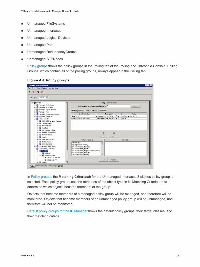
Policy groupsshows the policy groups in the Polling tab of the Polling and Threshold Console. PollingGroups, which contain all of the polling groups, always appear in the Polling tab.
Figure 4-1. Policy groups
In Policy groups, the Matching Criteriatab for the Unmanaged Interfaces Switches policy group isselected. Each policy group uses the attributes of the object type in its Matching Criteria tab todetermine which objects become members of the group.
Objects that become members of a managed policy group will be managed, and therefore will bemonitored. Objects that become members of an unmanaged policy group will be unmanaged, andtherefore will not be monitored.
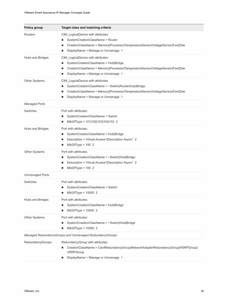
Default policy groups for the IP Managershows the default policy groups, their target classes, andtheir matching criteria.
VMware Smart Assurance IP Manager Concepts Guide
VMware, Inc. 32
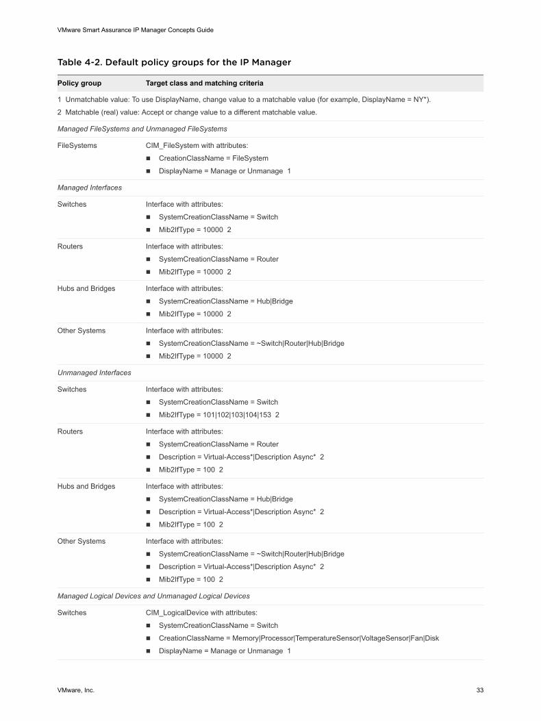
Table 4-2. Default policy groups for the IP Manager
Policy group Target class and matching criteria
1 Unmatchable value: To use DisplayName, change value to a matchable value (for example, DisplayName = NY*).
2 Matchable (real) value: Accept or change value to a different matchable value.
Managed FileSystems and Unmanaged FileSystems
FileSystems CIM_FileSystem with attributes:
n CreationClassName = FileSystem
n DisplayName = Manage or Unmanage 1
Managed Interfaces
Switches Interface with attributes:
n SystemCreationClassName = Switch
n Mib2IfType = 10000 2
Routers Interface with attributes:
n SystemCreationClassName = Router
n Mib2IfType = 10000 2
Hubs and Bridges Interface with attributes:
n SystemCreationClassName = Hub|Bridge
n Mib2IfType = 10000 2
Other Systems Interface with attributes:
n SystemCreationClassName = ~Switch|Router|Hub|Bridge
n Mib2IfType = 10000 2
Unmanaged Interfaces
Switches Interface with attributes:
n SystemCreationClassName = Switch
n Mib2IfType = 101|102|103|104|153 2
Routers Interface with attributes:
n SystemCreationClassName = Router
n Description = Virtual-Access*|Description Async* 2
n Mib2IfType = 100 2
Hubs and Bridges Interface with attributes:
n SystemCreationClassName = Hub|Bridge
n Description = Virtual-Access*|Description Async* 2
n Mib2IfType = 100 2
Other Systems Interface with attributes:
n SystemCreationClassName = ~Switch|Router|Hub|Bridge
n Description = Virtual-Access*|Description Async* 2
n Mib2IfType = 100 2
Managed Logical Devices and Unmanaged Logical Devices
Switches CIM_LogicalDevice with attributes:
n SystemCreationClassName = Switch
n CreationClassName = Memory|Processor|TemperatureSensor|VoltageSensor|Fan|Disk
n DisplayName = Manage or Unmanage 1
VMware Smart Assurance IP Manager Concepts Guide
VMware, Inc. 33
Policy group Target class and matching criteria
Routers CIM_LogicalDevice with attributes:
n SystemCreationClassName = Router
n CreationClassName = Memory|Processor|TemperatureSensor|VoltageSensor|Fan|Disk
n DisplayName = Manage or Unmanage 1
Hubs and Bridges CIM_LogicalDevice with attributes:
n SystemCreationClassName = Hub|Bridge
n CreationClassName = Memory|Processor|TemperatureSensor|VoltageSensor|Fan|Disk
n DisplayName = Manage or Unmanage 1
Other Systems CIM_LogicalDevice with attributes:
n SystemCreationClassName = ~Switch|Router|Hub|Bridge
n CreationClassName = Memory|Processor|TemperatureSensor|VoltageSensor|Fan|Disk
n DisplayName = Manage or Unmanage 1
Managed Ports
Switches Port with attributes:
n SystemCreationClassName = Switch
n Mib2IfType = 101|102|103|104|153 2
Hubs and Bridges Port with attributes:
n SystemCreationClassName = Hub|Bridge
n Description = Virtual-Access*|Description Async* 2
n Mib2IfType = 100 2
Other Systems Port with attributes:
n SystemCreationClassName = ~Switch|Hub|Bridge
n Description = Virtual-Access*|Description Async* 2
n Mib2IfType = 100 2
Unmanaged Ports
Switches Port with attributes:
n SystemCreationClassName = Switch
n Mib2IfType = 10000 2
Hubs and Bridges Port with attributes:
n SystemCreationClassName = Hub|Bridge
n Mib2IfType = 10000 2
Other Systems Port with attributes:
n SystemCreationClassName = ~Switch|Hub|Bridge
n Mib2IfType = 10000 2
Managed RedundancyGroups and Unmanaged RedundancyGroups
RedundancyGroups RedundancyGroup with attributes:
n CreationClassName = CardRedundancyGroup|NetworkAdapterRedundancyGroup|HSRPGroup|VRRPGroup
n DisplayName = Manage or Unmanage 1
VMware Smart Assurance IP Manager Concepts Guide
VMware, Inc. 34
Policy group Target class and matching criteria
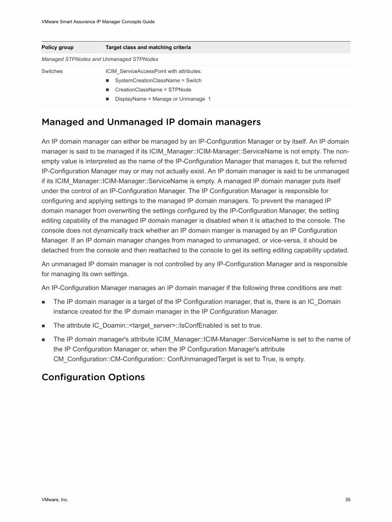
Managed STPNodes and Unmanaged STPNodes
Switches ICIM_ServiceAccessPoint with attributes:
n SystemCreationClassName = Switch
n CreationClassName = STPNode
n DisplayName = Manage or Unmanage 1
Managed and Unmanaged IP domain managers
An IP domain manager can either be managed by an IP-Configuration Manager or by itself. An IP domainmanager is said to be managed if its ICIM_Manager::ICIM-Manager::ServiceName is not empty. The non-empty value is interpreted as the name of the IP-Configuration Manager that manages it, but the referredIP-Configuration Manager may or may not actually exist. An IP domain manager is said to be unmanagedif its ICIM_Manager::ICIM-Manager::ServiceName is empty. A managed IP domain manager puts itselfunder the control of an IP-Configuration Manager. The IP Configuration Manager is responsible forconfiguring and applying settings to the managed IP domain managers. To prevent the managed IPdomain manager from overwriting the settings configured by the IP-Configuration Manager, the settingediting capability of the managed IP domain manager is disabled when it is attached to the console. Theconsole does not dynamically track whether an IP domain manger is managed by an IP ConfigurationManager. If an IP domain manager changes from managed to unmanaged, or vice-versa, it should bedetached from the console and then reattached to the console to get its setting editing capability updated.
An unmanaged IP domain manager is not controlled by any IP-Configuration Manager and is responsiblefor managing its own settings.
An IP-Configuration Manager manages an IP domain manager if the following three conditions are met:
n The IP domain manager is a target of the IP Configuration manager, that is, there is an IC_Domaininstance created for the IP domain manager in the IP Configuration Manager.
n The attribute IC_Doamin::<target_server>::IsConfEnabled is set to true.
n The IP domain manager's attribute ICIM_Manager::ICIM-Manager::ServiceName is set to the name ofthe IP Configuration Manager or, when the IP Configuration Manager's attributeCM_Configuration::CM-Configuration:: ConfUnmanagedTarget is set to True, is empty.
Configuration Options
VMware Smart Assurance IP Manager Concepts Guide
VMware, Inc. 35
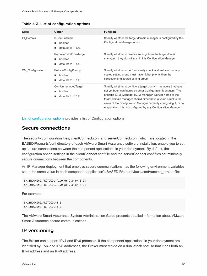
Table 4-3. List of configuration options
Class Option Function
IC_Domain IsConfEnabled
n boolean
n defaults to TRUE
Specify whether the target domain manager is configured by thisConfiguration Manager or not.
RemoveExtraFromTarget
n boolean
n defaults to TRUE
Specify whether to remove settings from the target domainmanager if they do not exist in this Configuration Manager.
CM_Configuration EnforceConfigPriority
n boolean
n defaults to TRUE
Specify whether to perform sanity check and enforce that anycopied setting group must have higher priority than thecorresponding source setting group.
ConfUnmanagedTarget
n boolean
n defaults to TRUE
Specify whether to configure target domain managers that havenot yet been configured by other Configuration Managers. Theattribute ICIM_Manager::ICIM-Manager::ServiceName of thetarget domain manager should either have a value equal to thename of the Configuration Manager currently configuring it, or beempty when it is not configured by any Configuration Manager.
List of configuration options provides a list of Configuration options.
Secure connections
The security configuration files, clientConnect.conf and serverConnect.conf, which are located in theBASEDIR/smarts/conf directory of each VMware Smart Assurance software installation, enable you to setup secure connections between the component applications in your deployment. By default, theconfiguration option settings in the clientConnect.conf file and the serverConnect.conf files set minimallysecure connections between the components.
An IP Manager deployment that employs secure communications has the following environment variablesset to the same value in each component application’s BASEDIR/smarts/local/conf/runcmd_env.sh file:
SM_INCOMING_PROTOCOL=[1,0 or 2,0 or 3,0]
SM_OUTGOING_PROTOCOL=[1,0 or 2,0 or 3,0]
For example:
SM_INCOMING_PROTOCOL=2,0
SM_OUTGOING_PROTOCOL=2,0
The VMware Smart Assurance System Administration Guide presents detailed information about VMwareSmart Assurance secure communications.
IP versioning
The Broker can support IPv4 and IPv6 protocols. If the component applications in your deployment areidentified by IPv4 and IPv6 addresses, the Broker must reside on a dual-stack host so that it has both anIPv4 address and an IPv6 address.
VMware Smart Assurance IP Manager Concepts Guide
VMware, Inc. 36
If all component applications in your deployment use the same IP protocol version, the Broker mustreside on a host with an IP address that accepts that protocol version. For example, if all componentapplications in your deployment support the IPv6 protocol, the Broker must reside on a host with an IPv6address. That host may be dual-stack or IPv6-only.
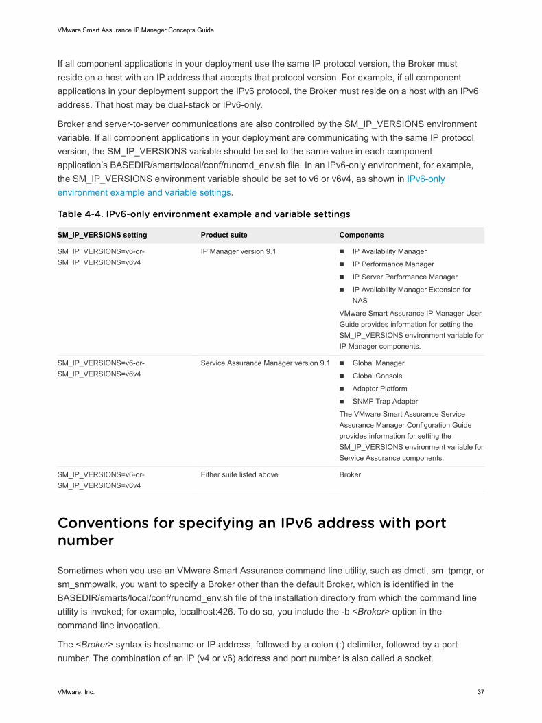
Broker and server-to-server communications are also controlled by the SM_IP_VERSIONS environmentvariable. If all component applications in your deployment are communicating with the same IP protocolversion, the SM_IP_VERSIONS variable should be set to the same value in each componentapplication’s BASEDIR/smarts/local/conf/runcmd_env.sh file. In an IPv6-only environment, for example,the SM_IP_VERSIONS environment variable should be set to v6 or v6v4, as shown in IPv6-onlyenvironment example and variable settings.
Table 4-4. IPv6-only environment example and variable settings
SM_IP_VERSIONS setting Product suite Components
SM_IP_VERSIONS=v6-or-SM_IP_VERSIONS=v6v4
IP Manager version 9.1 n IP Availability Manager
n IP Performance Manager
n IP Server Performance Manager
n IP Availability Manager Extension forNAS
VMware Smart Assurance IP Manager UserGuide provides information for setting theSM_IP_VERSIONS environment variable forIP Manager components.
SM_IP_VERSIONS=v6-or-SM_IP_VERSIONS=v6v4
Service Assurance Manager version 9.1 n Global Manager
n Global Console
n Adapter Platform
n SNMP Trap Adapter
The VMware Smart Assurance ServiceAssurance Manager Configuration Guideprovides information for setting theSM_IP_VERSIONS environment variable forService Assurance components.
SM_IP_VERSIONS=v6-or-SM_IP_VERSIONS=v6v4
Either suite listed above Broker
Conventions for specifying an IPv6 address with portnumber
Sometimes when you use an VMware Smart Assurance command line utility, such as dmctl, sm_tpmgr, orsm_snmpwalk, you want to specify a Broker other than the default Broker, which is identified in theBASEDIR/smarts/local/conf/runcmd_env.sh file of the installation directory from which the command lineutility is invoked; for example, localhost:426. To do so, you include the -b <Broker> option in thecommand line invocation.
The <Broker> syntax is hostname or IP address, followed by a colon (:) delimiter, followed by a portnumber. The combination of an IP (v4 or v6) address and port number is also called a socket.
VMware Smart Assurance IP Manager Concepts Guide
VMware, Inc. 37
“Conventions for specifying an IPv6 address with port number” section in Chapter 8, IPv6 AddressConventions, in the VMware Smart Assurance IP Manager Reference Guide provides information on thesyntax.
Conventions for specifying an IPv6 address in a classinstance name
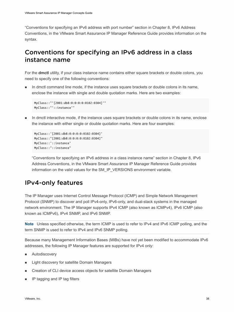
For the dmctl utility, if your class instance name contains either square brackets or double colons, youneed to specify one of the following conventions:
n In dmctl command line mode, if the instance uses square brackets or double colons in its name,enclose the instance with single and double quotation marks. Here are two examples:
MyClass::”’[2001:db8:0:0:0:0:0102:0304]’”
MyClass::”’::instance’”
n In dmctl interactive mode, if the instance uses square brackets or double colons in its name, enclosethe instance with either single or double quotation marks. Here are four examples:
MyClass::’[2001:db8:0:0:0:0:0102:0304]’
MyClass::”[2001:db8:0:0:0:0:0102:0304]”
MyClass::’::instance’
MyClass::”::instance”
“Conventions for specifying an IPv6 address in a class instance name” section in Chapter 8, IPv6Address Conventions, in the VMware Smart Assurance IP Manager Reference Guide providesinformation on the valid values for the SM_IP_VERSIONS environment variable.
IPv4-only features
The IP Manager uses Internet Control Message Protocol (ICMP) and Simple Network ManagementProtocol (SNMP) to discover and poll IPv4-only, IPv6-only, and dual-stack systems in the managednetwork environment. The IP Manager supports IPv4 ICMP (also known as ICMPv4), IPv6 ICMP (alsoknown as ICMPv6), IPv4 SNMP, and IPv6 SNMP.
Note Unless specified otherwise, the term ICMP is used to refer to IPv4 and IPv6 ICMP polling, and theterm SNMP is used to refer to IPv4 and IPv6 SNMP polling.
Because many Management Information Bases (MIBs) have not yet been modified to accommodate IPv6addresses, the following IP Manager features are supported for IPv4 only:
n Autodiscovery
n Light discovery for satellite Domain Managers
n Creation of CLI device access objects for satellite Domain Managers
n IP tagging and IP tag filters
VMware Smart Assurance IP Manager Concepts Guide
VMware, Inc. 38
n IPSec tunnel discovery
n Virtual router discovery
n Hot Standby Router Protocol (HSRP) and Virtual Router Redundancy Protocol (VRRP) discovery,monitoring, and analysis.
Understanding interface-matching filters
There are several reasons for wanting to exclude device-access interfaces from the discovered topology,foremost of which is to limit the interfaces that are discovered for access devices. An access device is anetwork device that contains interfaces (also known as access ports) that provide connections for endusers or node devices, such as routers or servers. Devices that are certified as access devices areidentified in the VMware Smart Assurance IP Certification Matrix.
To exclude interfaces for a discovered device, create an interface-matching filters for the device and addsthe filters to the tpmgr-param.conf file. The filters are based on the following interface table (ifTable)objects of the device’s MIB:
n ifIndex
n ifDescr
n ifType
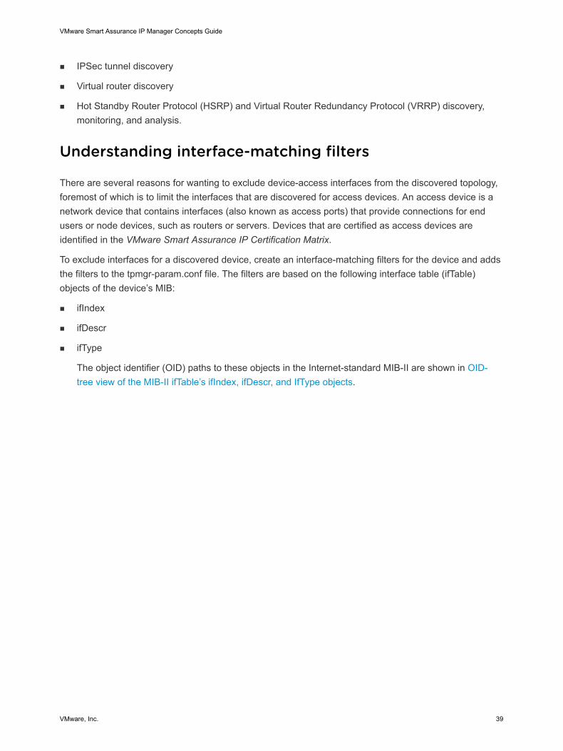
The object identifier (OID) paths to these objects in the Internet-standard MIB-II are shown in OID-tree view of the MIB-II ifTable’s ifIndex, ifDescr, and IfType objects.
VMware Smart Assurance IP Manager Concepts Guide
VMware, Inc. 39
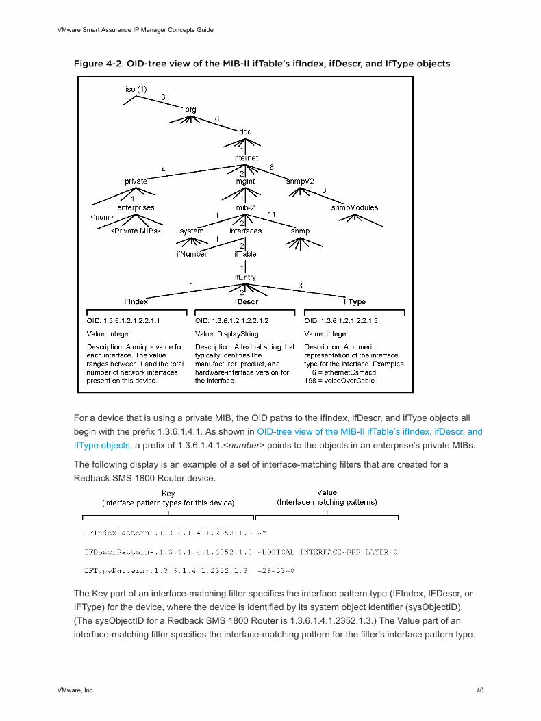
Figure 4-2. OID-tree view of the MIB-II ifTable’s ifIndex, ifDescr, and IfType objects
For a device that is using a private MIB, the OID paths to the ifIndex, ifDescr, and ifType objects allbegin with the prefix 1.3.6.1.4.1. As shown in OID-tree view of the MIB-II ifTable’s ifIndex, ifDescr, andIfType objects, a prefix of 1.3.6.1.4.1.<number> points to the objects in an enterprise’s private MIBs.
The following display is an example of a set of interface-matching filters that are created for aRedback SMS 1800 Router device.
The Key part of an interface-matching filter specifies the interface pattern type (IFIndex, IFDescr, orIFType) for the device, where the device is identified by its system object identifier (sysObjectID).(The sysObjectID for a Redback SMS 1800 Router is 1.3.6.1.4.1.2352.1.3.) The Value part of aninterface-matching filter specifies the interface-matching pattern for the filter’s interface pattern type.
VMware Smart Assurance IP Manager Concepts Guide
VMware, Inc. 40
Any interface retrieved from the target device that matches any interface-matching pattern for anyinterface pattern type for the device is included in the discovered topology. Conversely, any interfaceretrieved from the target device that does not match any of the interface-matching patterns isexcluded from the discovered topology.
As indicated in the example, a set of interface-matching filters for a device consists of three differentinterface pattern types:
n IFIndexPattern pertains to the ifIndex MIB object type.
n IFDescrPattern pertains to the ifDescr MIB object type.
n IFTypePattern pertains to the ifType MIB object type.
The default value (interface-matching pattern) for IFIndexPattern is “~*”, the default value forIFDescrPattern is “~*”, and the default value for IFTypePattern is “*”. As examples:
n IFIndexPattern-.1.3.6.1.4.1.164.6.1.3.183 ~*
n IFDescrPattern-.1.3.6.1.4.1.164.6.1.3.183 ~*
n IFTypePattern-.1.3.6.1.4.1.164.6.1.3.183 *
The “*” wildcard pattern matches anything, and the “~*” wildcard pattern matches nothing because ofthe leading tilde. Refer Chapter 9 Terminology for more information on wildcard syntax.
Each pattern type and its value is considered an interface-matching filter.
The interface-matching filters for a device are inclusive, meaning that if an interface that is retrievedfrom the target device matches just one of the matching patterns that are specified for IFIndexPattern,IFDescrPattern, or IFTypePattern, the interface will be included in the discovered topology. So, bydefault, because of the “*” in the IFTypePattern, all of the interfaces that are retrieved from the targetdevice are included in the topology.
Interface-matching filters in the tpmgr-param.conf file
Use the interface-matching filters in the tpmgr-param.conf configuration file as a starting point to configureinterface-matching filters for access devices. The tpmgr-param.conf file contains the IFTypePattern andIFDescrPattern interface-matching filters. These filters are listed in a table in the VMware SmartAssurance IP Manager Reference Guide. Modify any of these filters or add your own filters to the file.
Other interface-limiting parameter types in the tpmgr-param.conffile
The tpmgr-param.conf file also contains other interface-limiting parameter types, most of which are listedin a table in the VMware Smart Assurance IP Manager Reference Guide. The table includes an example,the default value, and the definition of each parameter type. Several parameter types in the table areinterface-matching filters that are also based on the ifIndex, ifDescr, and ifType objects. However, theyhave slightly different interface-matching pattern names and employ slightly different syntax than thestandard interface-matching filters previously discussed.
VMware Smart Assurance IP Manager Concepts Guide
VMware, Inc. 41

The VMware Smart Assurance IP Manager User Guide provides information on configuring interfacematching filters.
Understanding groups and settings
A group contains one or more settings, and a setting contains one or more parameters. Managed objects(systems discovered in the managed environment) become members of a group based on the matchingcriteria defined for the group.
How managed objects are assigned to groups
A managed object may be a member of one and only one group within a particular group category. Whenthe IP Manager performs discovery, it automatically assigns each managed object to one or more groupsbased on:
n The matching criteria defined for a group.
n The priority of a group, which determines membership when an object meets the matching criteria formore than one group within a particular group category.
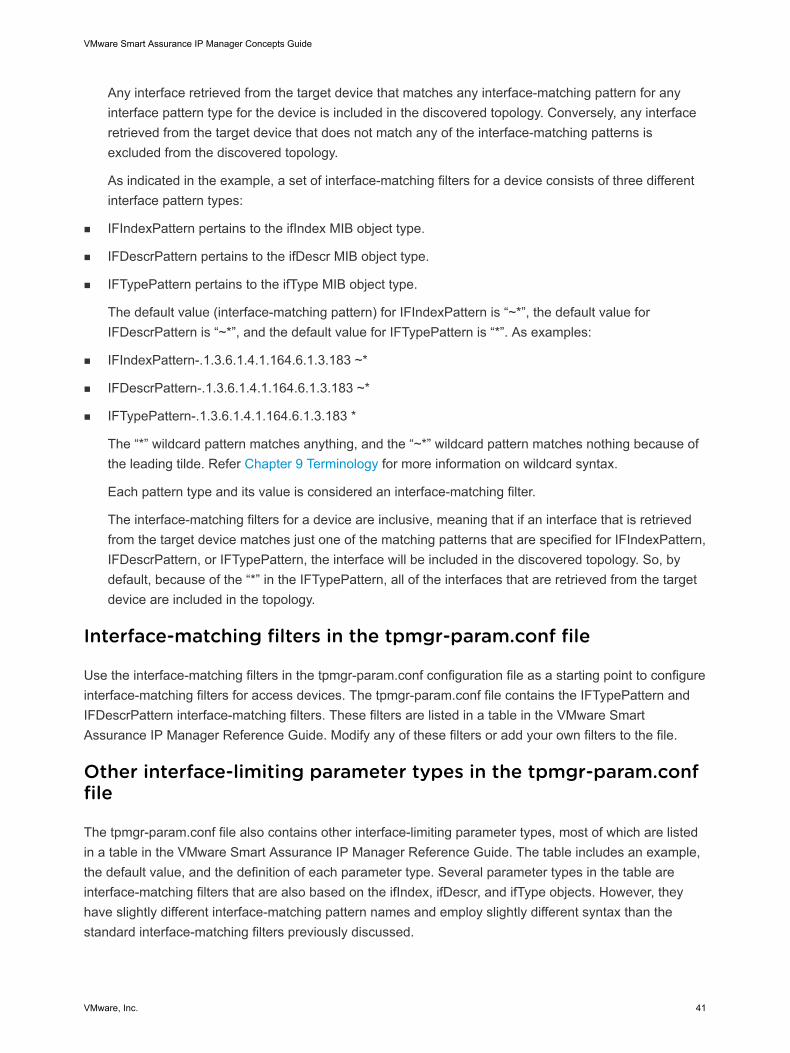
Relating managed objects to groups and settings illustrates the relationships between managedobjects, groups, and settings.
VMware Smart Assurance IP Manager Concepts Guide
VMware, Inc. 42
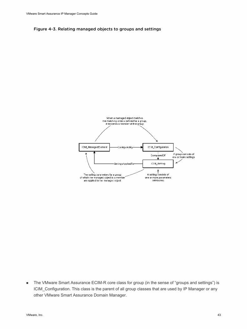
Figure 4-3. Relating managed objects to groups and settings
n The VMware Smart Assurance ECIM-R core class for group (in the sense of “groups and settings”) isICIM_Configuration. This class is the parent of all group classes that are used by IP Manager or anyother VMware Smart Assurance Domain Manager.
VMware Smart Assurance IP Manager Concepts Guide
VMware, Inc. 43
n The ECIM-R core class for setting is ICIM_Setting. This class is the parent of all setting classes thatare used by IP Manager or any other VMware Smart Assurance Domain Manager.
n The ECIM-R core class for managed object is ICIM_ManagedElement. This class is the parent of allmanaged object classes used by IP Manager or any other VMware Smart Assurance DomainManager.
Default groups and settings
The Polling, Thresholds, Device Access, and Tagging tabs of the Polling and Thresholds Console showthe default polling groups, the default threshold groups, the default device access groups, and the defaultIP tagging filter groups shipped with the IP Manager software.
The tabs also identify the matching criteria defined for each group, the default settings that are associatedwith each group, and the default parameter values that are associated with each setting. The VMwareSmart Assurance IP Manager Reference Guide provides information on all these settings.
Matching criteria
The matching criteria for a group are the attribute values defined for the target class that is associatedwith the group. For polling and threshold groups, the target class is Port, Interface, orUnitaryComputerSystem (such as a Switch, Router, Hub, or Bridge). For device access and IP taggingfilter groups, the target class is UnitaryComputerSystem.
Any managed object that meets the matching criteria for a group becomes a member of the group. Whena managed object becomes a member of a group, all parameter values that are defined for the group areapplied to the managed object.
Prioritized lists of groups
Within each group category (polling groups, threshold groups, device access groups, and IP tagging filtergroups), groups can be arranged in a high-to-low priority. A managed object is compared against thehighest priority group first and becomes a member of the first group for which there is a criteria match.
A managed object may become a member of different groups in different group categories, but amanaged object may only be a member of one group within a particular group category.
The VMware Smart Assurance IP Manager User Guide provides information on working with groups andsettings and the VMware Smart Assurance IP Manager Reference Guide provides information on Pollingsettings, Threshold settings, default polling groups, their target classes, matching criteria and their defaultsettings.
Understanding ICMP and SNMP polling
VMware Smart Assurance IP Manager Concepts Guide
VMware, Inc. 44
The IP Availability Manager and IP Performance Manager uses the Internet Control Message Protocol(ICMP) and Simple Network Management Protocol (SNMP) polling to monitor the IP network. The resultsof this polling are then compared to threshold values that define acceptable and unacceptable levels ofconnectivity or performance. The thresholds, in conjunction with traps, are used to diagnose the failed ordegraded objects that interrupt network connectivity or adversely affect network performance.
The monitoring of the network is controlled by ICMP and SNMP polling-related and threshold-relatedsettings that are created for the IP Availability Manager through the Polling and Thresholds Console.
This discussion focuses on the polling-related settings. Threshold related settings are described in theVMware Smart Assurance IP Manager User Guide.
ICMP and SNMP polling and analysis
The IP Manager and monitors the health of the IP network by periodically sending ICMP polls and SNMPpolls to the discovered network devices. The results of the polling are compared to threshold values thatdefine acceptable and unacceptable levels of connectivity or performance.
The polled data and the thresholds, in conjunction with received traps, are used by the IP AvailabilityManager to detect the failed or degraded objects that adversely affect network performance. In addition,the polled data, thresholds, and received traps are used by the IP Availability Manager to collect ordetermine status updates, which are imported by the IP Manager to diagnose the failed or degradedobjects that interrupt network connectivity.
The VMware Smart Assurance IP Manager User Guide provides a description of ICMP and SNMP pollingfor correlation analysis.
The VMware Smart Assurance IP Manager Reference Guide describe the events that are diagnosed bythe IP Managers.
Understanding polling groups and settings
Using the Polling and Thresholds Console, you can customize ICMP and SNMP polling for the IPAvailability Manager and IP Performance Manager by modifying default polling groups, or by creating newpolling groups. The polling groups periodically poll the managed IP devices to collect availability andperformance data.
The IP Availability Manager and IP Performance Manager uses the settings in a polling group to assignpolling parameters to a particular group of managed devices. From a polling and threshold perspective, asetting is a collection of parameters that are common to a particular type of analysis; for example,connectivity polling or environment polling.
Polling settings for IP availability monitoring
Through the polling settings for IP availability monitoring, you control the ICMP and SNMP connectivitypolling of the managed network objects in your network. The polled information serves as input to IPAvailability Manager‘s availability analysis of switches, routers, hubs, bridges, and other systems.
VMware Smart Assurance IP Manager Concepts Guide
VMware, Inc. 45
The IP Availability Manager provides the following polling settings for IP availability monitoring:
n Connectivity Polling
n Connectivity Polling - External Poller
n Connectivity Polling for IPv6 Addresses
n Connectivity Polling for IPv6 Addresses - External Poller
n Default IP_Route Connectivity Polling
The “Connectivity Polling” and “Connectivity Polling - External Poller” settings are mutually exclusive,which means that only one or the other (but not both) can be applied to a polling group at any giventime. The “Connectivity Polling for IPv6 Addresses” and “Connectivity Polling for IPv6 Addresses -External Poller” settings are also mutually exclusive.
The VMware Smart Assurance IP Manager Reference Guide provides information on connectivitypolling setting parameters and external poller settings.
Default IP_Route Connectivity Polling setting
The Default IP_Route Connectivity Polling setting determines the polling intervals that are used by the IPAvailability Manager to monitor default routes. The IP Availability Manager monitors the default routes byprobing the SNMP ipRouteTable (.1.3.6.1.2.1.4.21.0.0.0.0) on certain router devices.
Routers in an organization generally point the default route to the router that has a connection to anetwork service provider. By doing so, packets with destinations that are outside of the organization’s IPaddress space will be forwarded to that service provider. The default route address in IPv4 is 0.0.0.0/0.
The lack of a default route on a router is a good indication that an organization’s service provider ishaving connectivity issues.
When default-route polling fails, the IP Availability Manager generates a MissingDefaultRoute event.Specifically, the IPRoute object that is created as part of the Default IP_Route Connectivity Polling setting,itself, generates the MissingDefaultRoute event.
The VMware Smart Assurance IP Manager Reference Guide provides information on the DefaultIP_Route Connectivity Polling setting parameters.
Default polling groups
The IP Manager provides a polling category named “Polling Groups,” which contains the following defaultpolling groups:
n ComputeFabric
n MediaGateways
n 5620 SAM Managed Systems
n Proxy Devices
n Switches
VMware Smart Assurance IP Manager Concepts Guide
VMware, Inc. 46
n Routers
n Hubs and Bridges
n WirelessControllers
n WirelessAccessPoints
n WirelessClients
n Other Systems
Polling setting for optimization
Through the Cleanup Unused Monitoring Instances setting, you control the removal of instrumentationobjects that no longer have an associated managed object to monitor. This situation occurs when youremove a setting from a polling group.
For example, when you apply a setting such as Connectivity Polling to a polling group, the IP Managercreates the corresponding instrumentation objects. If you subsequently remove the Connectivity Pollingsetting from the polling group, the IP Manager responds in one of two ways:
n With theCleanup Unused Monitoring Instances setting applied to the polling group, the IP Managerremoves the corresponding instrumentation objects from memory.
n With the Cleanup Unused Monitoring Instances setting not applied to the polling group, the IPManager does not remove the corresponding instrumentation objects from memory.
By default, the Cleanup Unused Monitoring Instances setting is applied to the following pollinggroups:
n Switches
n Routers
n Hubs and Bridges
n Other Systems
“Default polling groups for the IP Manager” table in the VMware Smart Assurance IP ManagerReference Guide, provides the default polling groups, their target classes and matching criteria, andtheir default settings.
Settings affected by the Cleanup Unused Monitoring Instances setting lists the settings that areaffected by the Cleanup Unused Monitoring Instances setting.
Table 4-5. Settings affected by the Cleanup Unused Monitoring Instances setting
Polling setting Instrumentation objects created for these classes
Connectivity Polling n Card
n Interface
n Port
n EVCEndPoint
Connectivity Polling for IPv6 Addresses n IPv6
VMware Smart Assurance IP Manager Concepts Guide
VMware, Inc. 47
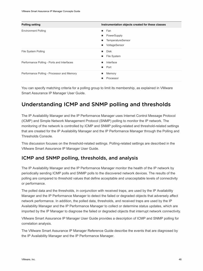
Polling setting Instrumentation objects created for these classes
Environment Polling n Fan
n PowerSupply
n TemperatureSensor
n VoltageSensor
File System Polling n Disk
n File System
Performance Polling - Ports and Interfaces n Interface
n Port
Performance Polling - Processor and Memory n Memory
n Processor
You can specify matching criteria for a polling group to limit its membership, as explained in VMwareSmart Assurance IP Manager User Guide.
Understanding ICMP and SNMP polling and thresholds
The IP Availability Manager and the IP Performance Manager uses Internet Control Message Protocol(ICMP) and Simple Network Management Protocol (SNMP) polling to monitor the IP network. Themonitoring of the network is controlled by ICMP and SNMP polling-related and threshold-related settingsthat are created for the IP Availability Manager and the IP Performance Manager through the Polling andThresholds Console.
This discussion focuses on the threshold-related settings. Polling-related settings are described in theVMware Smart Assurance IP Manager User Guide.
ICMP and SNMP polling, thresholds, and analysis
The IP Availability Manager and the IP Performance Manager monitor the health of the IP network byperiodically sending ICMP polls and SNMP polls to the discovered network devices. The results of thepolling are compared to threshold values that define acceptable and unacceptable levels of connectivityor performance.
The polled data and the thresholds, in conjunction with received traps, are used by the IP AvailabilityManager and the IP Performance Manager to detect the failed or degraded objects that adversely affectnetwork performance. In addition, the polled data, thresholds, and received traps are used by the IPAvailability Manager and the IP Performance Manager to collect or determine status updates, which areimported by the IP Manager to diagnose the failed or degraded objects that interrupt network connectivity.
VMware Smart Assurance IP Manager User Guide provides a description of ICMP and SNMP polling forcorrelation analysis.
The VMware Smart Assurance IP Manager Reference Guide describe the events that are diagnosed bythe IP Availability Manager and the IP Performance Manager.
VMware Smart Assurance IP Manager Concepts Guide
VMware, Inc. 48
Understanding threshold groups and settings
Using the Polling and Thresholds Console, you can customize ICMP and SNMP polling thresholds for theIP Availability Manager and the IP Performance Manager by modifying default threshold groups, or bycreating new threshold groups.
The IP Availability Manager and the IP Performance Manager use the settings in a threshold group toassign threshold parameters to a particular group of managed devices, interfaces, or ports. From a pollingand threshold perspective, a setting is a collection of parameters that are common to a particular type ofanalysis; for example, connectivity polling or environment polling.
Understanding device access groups and settings
Because the IP Manager is a component of many VMware Smart Assurance deployments, the IPAvailability Manager has been selected as the central repository for storing the device access credentialsfor other Domain Managers — such as command line interface (CLI) login credentials required byNetwork Protocol Manager for EIGRP and Network Protocol Manager for IS-IS to perform CLI discoveryand, optionally, CLI polling. The satellite Domain Managers import the device access credentials as wellas initial topology from IP Availability Manager when they add IP Availability Manager as a source.
Polling settings for IP performance monitoring
Through the polling settings for IP performance monitoring, you control the ICMP and SNMP performancepolling of the managed network objects in your network. The polled information serves as input to IPPerformance Manager‘s fault and performance analysis of interfaces and ports, processors and memory,disks and file systems, fans and power supplies, and voltage and temperature sensors.
The IP Performance Manager provides the following polling settings for IP performance monitoring:
n Environment Polling
n Environment Polling - External Poller
n File System Polling
n Performance Polling - Ports and Interfaces
n Performance Polling - Processor and Memory
The “Environment Polling” and “Environment Polling - External Poller” settings are mutually exclusive,which means that only one or the other (but not both) can be applied to a polling group at any giventime.
Environment Polling setting
The Environment Polling setting configures the polling intervals that are used to monitor systemcomponents such as the fan, memory, power supply, temperature sensor, and voltage sensor objects.
VMware Smart Assurance IP Manager Concepts Guide
VMware, Inc. 49
The VMware Smart Assurance IP Manager Reference Guide provides information on the EnvironmentPolling setting parameters.
Environment Polling - External Poller
The Environment Polling - External Poller setting serves two purposes:
n Provides a means of testing the system-component instrumentation and analysis functionality of theIP Performance Manager.
n Provides a means for the IP Performance Manager to import system-component status updates froman VMware Smart Assurance adapter, such as the Adapter for Alcatel-Lucent 5620 SAM EMS.
The VMware Smart Assurance IP Manager Reference Guide provides information on theEnvironment Polling - External Poller setting parameters.
File System Polling setting
The File System Polling setting configures the polling intervals that are used to monitor a host system’sfile system. This setting is a valid choice only for the Other Systems polling group.
The VMware Smart Assurance IP Manager Reference Guide provides information on the File SystemPolling setting parameters.
Performance Polling - Ports and Interfaces setting
The Performance Polling - Ports and Interfaces setting configures the polling intervals that are used tomonitor the performance of managed ports and interfaces.
The VMware Smart Assurance IP Manager Reference Guide provides information on the PerformancePolling - Ports and Interfaces setting parameters.
Performance Polling - Processor and Memory setting
The Performance Polling - Processor and Memory setting configures the polling intervals that are used tomonitor a system’s processor and associated memory objects.
The VMware Smart Assurance IP Manager Reference Guide provides information on the PerformancePolling - Processor and Memory setting parameters.
Thresholds tab
The IP Manager provides the following categories of threshold groups, each of which contains defaultthreshold groups:
n File Systems
n Interface Groups
n Port Groups - Access Ports
VMware Smart Assurance IP Manager Concepts Guide
VMware, Inc. 50
n Port Groups - Trunk Ports
n System Resource Groups
n System VLAN Tag Groups
n TemperatureSensor
n VoltageSensor
n VLAN Impact Propagation Groups
The “VLAN Impact Propagation Groups” category does not automatically appear. You must issue acertain command for the VLAN Impact Propagation Groups category to appear.
File Systems
File system is treated as a logical network object. The File System Management functionality allows youto define and configure thresholds for file system space utilization.
In the earlier version, a single threshold value is set for all file systems using the System Resource group.The disadvantage is that each file system cannot be monitored individually.
The following enhancements are added:
n Ability to define thresholds for each file system instance
n Ability to define thresholds using the current wildcard mechanism. Wildcards are enabled to be usedto define inclusion and/or exclusion lists of either servers or file systems.
n Ability to change default thresholds per file system
n Ability to manage and unmanage file systems
Define thresholds for individual file system instances
You can now configure thresholds for individual file system instances. A default group called File Systemis available.
The utilization thresholds can be configured for each file system instance. As a result, a host with multiplefile systems can have different thresholds defined individually for each file system instance. Each filesystem instance is monitored individually.
VMware Smart Assurance IP Manager Concepts Guide
VMware, Inc. 51
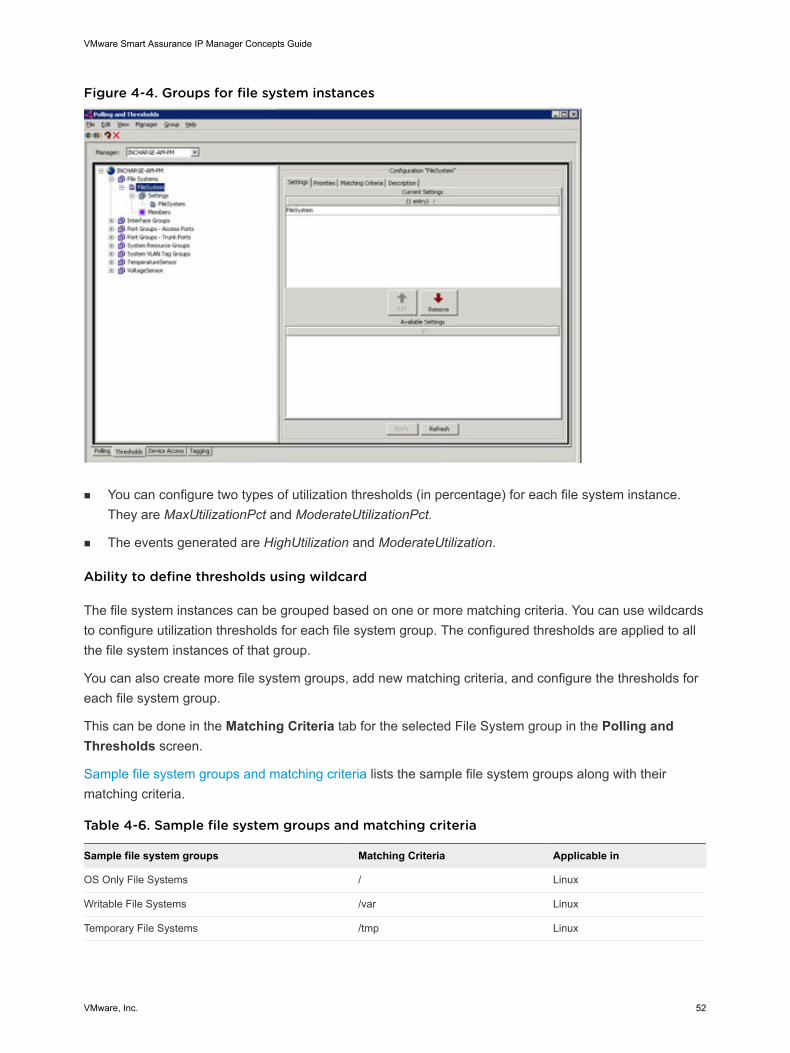
Figure 4-4. Groups for file system instances
n You can configure two types of utilization thresholds (in percentage) for each file system instance.They are MaxUtilizationPct and ModerateUtilizationPct.
n The events generated are HighUtilization and ModerateUtilization.
Ability to define thresholds using wildcard
The file system instances can be grouped based on one or more matching criteria. You can use wildcardsto configure utilization thresholds for each file system group. The configured thresholds are applied to allthe file system instances of that group.
You can also create more file system groups, add new matching criteria, and configure the thresholds foreach file system group.
This can be done in the Matching Criteria tab for the selected File System group in the Polling andThresholds screen.
Sample file system groups and matching criteria lists the sample file system groups along with theirmatching criteria.
Table 4-6. Sample file system groups and matching criteria
Sample file system groups Matching Criteria Applicable in
OS Only File Systems / Linux
Writable File Systems /var Linux
Temporary File Systems /tmp Linux
VMware Smart Assurance IP Manager Concepts Guide
VMware, Inc. 52
Sample file system groups Matching Criteria Applicable in
Non Critical File Systems User defined
Unclassified File Systems User defined
Events and thresholds for file systems
The VMware Smart Assurance IP Manager Reference Guide provides the events and thresholds for filesystems along with their description.
The thresholds defined in the System Resource Group serve as the default and may be overwritten byvalues in one of the new File System groups. If a file system instance belongs to a particular File Systemgroup, it inherits the group’s threshold settings. In case it does not belong to any group, the thresholds inthe System Resource group that the device belongs to will apply.
When new file system groups are created, they do not have any matching criteria and are empty. You canadd new matching criteria and configure the thresholds for each file system group. This can be done inthe Matching Criteria tab for the selected file system group in the Polling and Thresholds window.
Each file system group is placed in the order of priority in the Polling and Thresholds window. You canchange the priority from the Priority tab. The matching of the file system instances begin from the highestpriority group and continues in the order of priority. A file system instance that matches a group is notconsidered for matching with the remaining groups.Sample file system groups and matching criteria
The VMware Smart Assurance IP Manager Reference Guide lists sample file system groups, theirdescription, and their matching criteria. You can use those as a guide to create file system groupsmanually.Managing or unmanaging file systems
You can manage or unmanage an individual file system instance. When a file system is renderedmanaged, that file system instance is monitored. On the other hand, when a file system instance isrendered unmanaged, that file system instance is not monitored.
The VMware Smart Assurance IP Manager User Guide provides information on how to manage andunmanage file systems.
Attribute of file system describes the attribute for a file system instance.
Table 4-7. Attribute of file system
Attribute Description Allowed values
IsManaged Determines if a file system instance should be monitored by themanagement system. An unmanaged object does not have anyassociated instrumentation. This attribute is read-only.
Boolean: True or False
Default: True
Migration impacts
“Migrate data from older IP deployments” section in Chapter 4, Performing Migration, in the VMwareSmart Assurance Installation Guide for SAM, IP, ESM, MPLS, and NPM Managers provides moreinformation about migrating settings.
VMware Smart Assurance IP Manager Concepts Guide
VMware, Inc. 53
Interface Groups
Threshold groups for interfaces are used to configure parameters for interface analysis. Thresholds aredetermined by the interface’s media type (for example, Ethernet or ATM) and its role (primary, backup, ordial-on-demand).
The VMware Smart Assurance IP Manager Reference Guide provides information on the default interfacethreshold groups, their target classes and matching criteria, and their default settings. The target class forall interface threshold groups is Interface.
n The default group-to-setting mappings in the table are the mappings that users would typically use.The settings that are available to an interface threshold group are as follows:
n Backup Interface Support
n Dial-on-Demand Interface Support
n Disable Fault Analysis for Interface/Port
n Disable Performance Analysis for Interface/Port
n Ethernet Interface/Port Performance
n Generic Interface/Port Performance
n Interface/Port Flapping
n The “Other Interfaces” threshold group has the lowest priority. Managed interfaces that do not matchthe criteria for the other interface threshold groups become members of the Other Interfacesthreshold group.
n Only discovered objects that match the type and attribute values in the “Target class and matchingcriteria” column for a particular group can become members of that group.
n By default, all discovered objects that match the type and attribute values in the "Target class andmatching criteria" column for a particular group become members of that group.
You can specify matching criteria for a threshold group to limit its membership.
Port Groups - Access Ports
Threshold groups for access ports are used to configure parameters for access port analysis. Thresholdsare determined by the access port’s media type; for example, Ethernet or ATM.
An access port is a port that provides a connection for end users or node devices, such as routers orservers. An access port becomes managed if it has a connection or is explicitly managed.
VMware Smart Assurance IP Manager Concepts Guide
VMware, Inc. 54
The VMware Smart Assurance IP Manager Reference Guide provides information on the default accessport threshold groups, their target classes and matching criteria, and their default settings. The targetclass for all access port threshold groups is Port.
n The default group-to-setting mappings in the table are the mappings that users would typically use.The settings that are available to an access port threshold group are as follows:
n Disable Fault Analysis for Interface/Port
n Disable Performance Analysis for Interface/Port
n Ethernet Interface/Port Performance
n Generic Interface/Port Performance
n Interface/Port Flapping
n The “Other Ports” threshold group has the lowest priority. Managed access ports that do not matchthe criteria for the other access port threshold groups become members of the Other Ports thresholdgroup.
Port Groups - Trunk Ports
Threshold groups for trunk ports are used to configure parameters for trunk port analysis. Thresholds aredetermined by the trunk port’s media type; for example, Ethernet or ATM.
A trunk port is any port that connects to another port or interface on a device that participates in the Layer2 bridging protocol. By default, all trunk ports are managed, which means that by default all trunk portscan be associated with trunk port threshold groups.
Because trunk ports are inherently more critical than access ports, trunk port threshold groups typicallyhave lower thresholds than access port threshold groups for utilization, errors, and so on. That is, thethresholds for trunk port threshold groups are more stringent than the thresholds for access port thresholdgroups.
The VMware Smart Assurance IP Manager Reference Guide provides information on the default trunkport threshold groups, their target classes and matching criteria, and their default settings. The targetclass for all trunk port threshold groups is Port.
n The default group-to-setting mappings in the table are the mappings that users would typically use.The settings that are available to a trunk port threshold group are as follows:
n Disable Fault Analysis for Interface/Port
n Disable Performance Analysis for Interface/Port
n Ethernet Interface/Port Performance
n Generic Interface/Port Performance
n Interface/Port Flapping
n The “Other Ports” threshold group has the lowest priority. Managed trunk ports that do not match thecriteria for the other trunk port threshold groups become members of the Other Ports threshold group.
VMware Smart Assurance IP Manager Concepts Guide
VMware, Inc. 55
System Resource Groups
Threshold groups for system resources are used to configure parameters for system analysis. Thesensitivity of the system thresholds is determined by the role of the system.
The VMware Smart Assurance IP Manager Reference Guide provides information on the default systemresource threshold groups, their target classes and matching criteria, and their default settings. The targetclass for all system resource threshold groups is UnitaryComputerSystem.
n The default group-to-setting mappings in the table are the mappings that users would typically use.The settings that are available to a system resource threshold group are as follows:
n Cisco Fast and NvRam Memory
n Connectivity
n Environment
n File System
n Interface Management Policy
n Juniper Environment
n Processor and Memory
n VLAN Tagging Policy
n The “Other Systems” group has the lowest priority. Managed systems that do not match the criteriafor the other system resource threshold groups become members of the Other Systems group. Forexample, managed host systems become members of the Other Systems group.
System VLAN Tag Groups
Threshold groups for VLAN tagging are used to ensure that systems are assigned to their appropriateVLAN. These groups are described in the VMware Smart Assurance IP Manager User Guide, under“Performing tasks in the Thresholds tab”.
The VMware Smart Assurance IP Manager Reference Guide provides information on the default systemVLAN tag groups, their target classes and matching criteria, and their default settings. The target class forall system VLAN tag groups is UnitaryComputerSystem.
n Even though the following settings are available to a system VLAN tag group, only the “VLAN TaggingPolicy” setting is valid:
n Cisco Fast and NvRam Memory
n Connectivity
n Environment
n File System
n Interface Management Policy
n Juniper Environment
VMware Smart Assurance IP Manager Concepts Guide
VMware, Inc. 56

n Processor and Memory
n VLAN Tagging Policy
n The “Other Systems” group has the lowest priority. Managed systems that do not match the criteriafor the Switches system VLAN tag group become members of the Other Systems group. Forexample, managed host systems become members of the Other Systems group.
Thresholds for temperature and voltage sensors
Voltage and Temperature thresholds are set to generate alarms when the actual values in the devicescross the defined threshold values.
Two types of values can be set for voltage threshold, that is, high and low voltage threshold. Only onethreshold can be set for the temperature sensor, that is, the high temperature threshold. Accordingly, twotypes of alarms can be generated for voltage sensors, and only one alarm can be generated for thetemperature sensor.
You can configure separate thresholds for different voltage and temperature sensors in the same device.
Note The threshold values set at the Instance level take precedence over those set at the Device Type(System Resource Group) level. When no values are specified at Instance level, Device level thresholdvalues prevail. Additionally, if the value for the parameter, UseMIBThresholds is set to TRUE, the MIBvalues will take precedence over the threshold values set at IP for alarm generation.
By default, the following are available:
n Groups called TemperatureSensor and VoltageSensor. These groups are empty and do not matchany temperature or voltage sensors.
n The thresholds defined in the System Resource Group serve as the default and may be overwrittenby values in one of the new groups.
If a temperature sensor or voltage sensor belongs to a particular group, it inherits the group’sthreshold setting. In case it does not belong to any group, the thresholds in the System Resourcegroup will apply.
Creating separate thresholds for voltage and temperature sensors
To create separate thresholds for different voltage and temperature sensors (or a group of sensors), youmust create groups by using appropriate matching criteria.
VMware Smart Assurance IP Manager Concepts Guide
VMware, Inc. 57
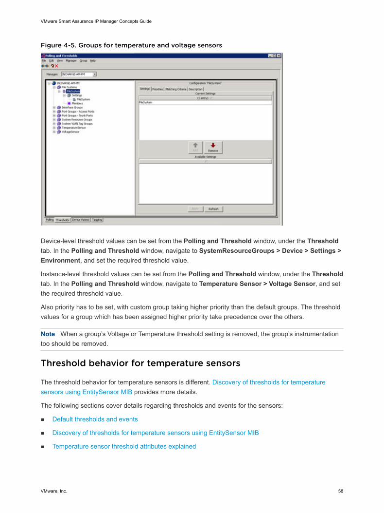
Figure 4-5. Groups for temperature and voltage sensors
Device-level threshold values can be set from the Polling and Threshold window, under the Thresholdtab. In the Polling and Threshold window, navigate to SystemResourceGroups > Device > Settings >Environment, and set the required threshold value.
Instance-level threshold values can be set from the Polling and Threshold window, under the Thresholdtab. In the Polling and Threshold window, navigate to Temperature Sensor > Voltage Sensor, and setthe required threshold value.
Also priority has to be set, with custom group taking higher priority than the default groups. The thresholdvalues for a group which has been assigned higher priority take precedence over the others.
Note When a group’s Voltage or Temperature threshold setting is removed, the group’s instrumentationtoo should be removed.
Threshold behavior for temperature sensors
The threshold behavior for temperature sensors is different. Discovery of thresholds for temperaturesensors using EntitySensor MIB provides more details.
The following sections cover details regarding thresholds and events for the sensors:
n Default thresholds and events
n Discovery of thresholds for temperature sensors using EntitySensor MIB
n Temperature sensor threshold attributes explained
VMware Smart Assurance IP Manager Concepts Guide
VMware, Inc. 58
Threshold settings
Default thresholds and events
The table “Events and thresholds for temperature and voltage sensors” in the VMware Smart AssuranceIP Manager Reference Guide provides information on the default threshold setting and events generatedfor temperature and voltage sensors.
Discovery of thresholds for temperature sensors using EntitySensor MIB
Temperature sensor thresholds can be set during discovery for devices that are certified in the IPManager using EntitySensor MIB for Environment. To verify if threshold values are discovered from theMIB, you must enable MetaClass and verify the Instrumentation Class(TemperatureSensor_Fault_CiscoEntityFRU) of the specific temperature sensor object.
There are two possibilities for setting the threshold value of the temperature sensors:
n If the threshold values returned by the agent are greater than 0, discovery reads in the thresholdvalues from the EntitySensor MIB and automatically sets the thresholds in the instrumentation objectto the values from the agent.
n If the device agent does not return a positive value for the threshold reading, then the threshold valuefalls back to the default setting defined in either the TemperatureSensor group or in the SystemResource group.
Temperature sensor threshold attributes explained
The following attributes are explained in the VMware Smart Assurance IP Manager Reference Guide:
n MajorAlarmThreshold
n MibEntSensorThreshold
n CurrentValue
n RelativeTemperatureThreshold
n TemperatureHighThreshold
n HighThreshold
VLAN Impact Propagation Groups
Threshold groups for VLAN impact propagation are used to prevent device impact propagation in certain(user-specified) VLANs, such as management VLANs and default VLANs. These groups are described inthe VMware Smart Assurance IP Manager User Guide, under “Performing tasks in the Thresholds tab”.The default VLAN impact propagation groups do not automatically appear. You must issue a certaincommand for the default VLAN impact propagation groups to appear.
VMware Smart Assurance IP Manager Concepts Guide
VMware, Inc. 59
The VMware Smart Assurance IP Manager Reference Guide provides information on the default VLANimpact propagation groups, their target classes and matching criteria, and their default settings. Thetarget class for all VLAN impact propagation groups is VLAN.
n The only setting that is available to a VLAN impact propagation group is “Problem Impact propagationpolicy over VLANs.” The VMware Smart Assurance IP Manager Reference Guide providesinformation on the “Problem Impact propagation policy over VLANs” setting parameters
n The Other VLANs group has the lowest priority. VLANs that do not match the criteria for the VLANsgroup become members of the Other VLANs group.
Threshold settings for IP availability monitoring
Through the threshold settings for IP availability monitoring, you control the ICMP and SNMP connectivitypolling thresholds of the managed network objects in your network. The polled information serves as inputto IP Availability Manager‘s availability analysis of switches, routers, hubs, bridges, and other systems.
The IP Manager provides the following threshold settings for IP availability monitoring:
n Backup Interface Support
n Connectivity
n Dial-on-Demand Interface Support
n Interface/Port Flapping
The VMware Smart Assurance IP Manager Reference Guide provides more information on thethreshold settings for IP availability monitoring.
Threshold settings for IP performance monitoring
Through the threshold settings for IP performance monitoring, you control the ICMP and SNMPperformance polling thresholds of the managed network objects in your network. The polled informationserves as input to IP Performance Manager‘s fault and performance analysis of interfaces and ports,processors and memory, disks and file systems, fans and power supplies, and voltage and temperaturesensors.
The IP Manager provides the following threshold settings for IP performance monitoring:
n Ethernet Interface/Port Performance
n Generic Interface/Port Performance
n Cisco Fast and NvRam Memory
n Environment
n File System
n Juniper Environment
n Processor and Memory
VMware Smart Assurance IP Manager Concepts Guide
VMware, Inc. 60
The VMware Smart Assurance IP Manager Reference Guide provides more information on thethreshold settings for IP performance monitoring.
Understanding the IP tagging feature
In a networked environment, the same IP addresses can be reused across multiple systems (devices)running in separate networks. These IP addresses, known as overlapping IP addresses, are prominent inMPLS VPN environments and in networks centrally managed by Managed Service Providers, whereprivate IP networks of customers often deploy identically numbered IP address spaces. Example of anoverlapping IP in an MPLS VPN network is an example of an overlapping IP address in an MPLS VPNnetwork.
VMware Smart Assurance IP Manager Concepts Guide
VMware, Inc. 61
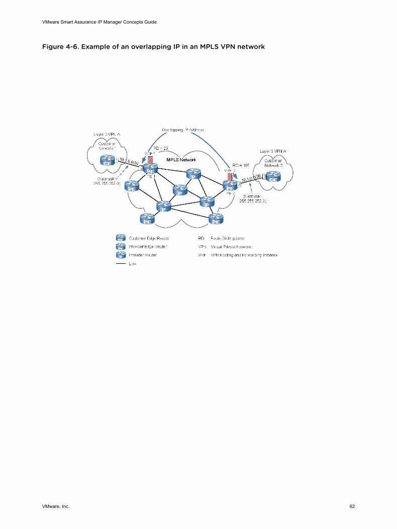
Figure 4-6. Example of an overlapping IP in an MPLS VPN network
VMware Smart Assurance IP Manager Concepts Guide
VMware, Inc. 62
Overlapping IP addresses do not create problems across different networks; however, when a service-assurance application for a centrally managed network attempts to discover the overlapping IPaddresses, IP address identity problems arise. For example, without the IP tagging feature, the IPManager will respond as follows when it discovers an overlapping IP address:
n Create a DuplicateIP notification and a DuplicateIP object.
n Discard the most recently received overlapping address.
n Remove the initially received overlapping address from its repository.
With the IP tagging feature, the IP Manager is able to distinguish between overlapping addressesbelonging to different customers by adding a distinguishing tag to their names.
That is, instead of using the standard naming scheme of “IP-<IP address>” to name an overlapping IPaddress instance, the IP Manager uses the “IP-<IP address>/<tag>” naming scheme to name theinstance.
IP tagging scenario
Consider the following scenario:
n In the managed network environment, two switches (SW1, SW2) in one customer network and twoswitches (SW3, SW4) in another customer network are using the same IP address space.
n Without creating an IP tag group for at least one of the customer networks, the IP Manager willdiscard the overlapping IP addresses collected from the four switches.
n By creating an IP tag group for at least one of the customer networks, the IP Manager will assign onename to the IP addresses collected from SW1 and SW2, and assign a different name to the IPaddresses collected from SW3 and SW4.
n For example, if you create an IP tag group having a “York” tag and matching criteria that allow SW1and SW2 to become members of the group, the IP Manager will assign the name IP-<IP address>/York to the IP addresses collected from SW1 and SW2, and assign the name IP-<IP address> to theIP addresses collected from SW3 and SW4.
With the IP tagging feature, create an IP tag filter for each group of systems that is using anoverlapping address space. Included in each filter is a user-specified tag value and a range ofoverlapping IP addresses.
Why modeling overlapping IP addresses is important
Through the IP tag filters, the IP Manager is able to create IP objects in the modeled topology thatrepresent the overlapping IP addresses that are used by locally distinct groups of systems. This capabilityleads to better modeling of the managed network environment, which in turn leads to more accuratecorrelation analysis results.
VMware Smart Assurance IP Manager Concepts Guide
VMware, Inc. 63
An overlapping IP address is often on a client-side physical interface of a router or switch managed by aManaged Service Provider (MSP). The MSP wants to discover the router and all of its interfaces and IPaddresses, but does not want to (and often cannot) discover the client equipment accessible through theoverlapping IP address. The inclusion of the overlapping IP addresses in the modeled topology allows theMSP to observe the status of the client equipment that is associated with the overlapping IP addresses,which enables the MSP to respond immediately to customer outages.
The IP Manager monitors the status of the overlapping IP addresses by periodically sending ICMP andSNMP requests to the systems on which the overlapping IP addresses were discovered.
Overlapping IP addresses versus management IP addresses
An overlapping IP address is typically an address on an edge system’s physical interface, not the address— known as a management IP address — bound to the edge system’s SNMP agent. (An edge system isa system at the edge of the managed network environment.) An overlapping IP address is typicallyunreachable in the sense that no routes exist between the host running the IP Manager and theoverlapping IP address.
Note A management IP address is the address that the IP Manager uses to discover information abouta system and to monitor the system after it is discovered.
Managed IP objects versus unmanaged IP objects
Even for a pair of overlapping IP addresses that are reachable by the IP Manager, the IP Manager will notbe able to monitor them because it will not be able to determine which of the systems bound to those IPaddresses is responding to the ICMP or SNMP polls. If one of the overlapping IP address is reachableand the other is not, managing the reachable one and unmanaging the unreachable one would makesense.
The “Unmanage admin down” feature addresses this scenario where a duplicate IP in the network comesin picture due to network configuration change. In such a situation, one interface related to the duplicateIP may be set as “administratively down,” as it is not participating in the network. Once the interface isdown, the IP related to this particular interface is not discovered, while the other IP remains as it is. The“EnableUnmanageAdminDown” in the tpmgr-param.conf file enables or disables this functionality.
Note The “Unmanage admin down” and the “IP tagging” features are mutually exclusive. To utilize the"Unmanage admin down" functionality, it is required that the IP tagging for that specific set of IPs isremoved and then the "unmanage admin down" feature is enabled.
By default, an IP tag filter sets all IP objects created for overlapping IP addresses to “unmanaged,” andsets all IP objects created for management IP addresses to “managed.” A managed object is monitoredby using ICMP and SNMP — unless different access mode is specified — to determine the object’s statusand connectivity. An unmanaged object is not polled or rediscovered but remains present in the modeledtopology.
The VMware Smart Assurance IP Manager User Guide provides more information about managed andunmanaged objects.
VMware Smart Assurance IP Manager Concepts Guide
VMware, Inc. 64
Automatic and user-defined IP tagging
The IP tagging feature provides two levels of IP tagging:
n Automatic
n User-defined
By default, no IP tagging occurs. After you edit the BASEDIR/smarts/conf/discovery/tpmgr-param.conf file and change the DisableOverlappingIP value to FALSE, automatic IP tagging isavailable.
Automatic tagging
Automatic IP tagging works as enumerated below:
1 For every MPLS-related VRF IP address collected for a discovered system, the IP Manager createsan IP object and tags its name with the route distinguisher (RD) tag value that is associated with theVRF to which the VRF IP address belongs. The IP Manager obtains the RD tag by reading the vendorVPN MIB on the discovered system.
2 The IP Manager tags the name of the IP object with a route distinguisher value regardless of whetherthe VRF IP is — or is not — an overlapping IP address.
The IP Manager also creates a corresponding IPNetwork object and tags it with the same value thatis used to tag the IP objects. The IP objects have a ConnectedVia relationship with the IPNetworkobject.
Note Automatic IP tagging is also known as VRF IP tagging.
User-defined tagging
User-defined IP tagging occurs when you create an IP tag filter group in IP Availability Manager or IPPerformance Manager based on specific deployment and specifies a tag value and an overlapping IPaddress range for the group. The user-specified tag may be applied to both non-VRF overlapping IPaddresses and VRF IP addresses, where a non-VRF overlapping IP address is defined as an overlappingIP address that is not part of an MPLS Layer 3 VPN. In addition, users can configure an IP tag filter groupto double-tag the name of the objects created for discovered VRF IP addresses, or to replace the routedistinguisher tag in the name of these objects with the user-specified tag.
For every IP address that falls within the overlapping IP address range of an IP tag filter group, the IPManager creates an IP object and tags its name with the user-specified value. The IP Manager alsocreates a corresponding IPNetwork object and tags it with the same value that is used to tag the IPobjects. (The IP objects have a ConnectedVia relationship with the IPNetwork object.)
IP tag naming scheme
VMware Smart Assurance IP Manager Concepts Guide
VMware, Inc. 65
The tagged name of a IP or IPNetwork object is defined in the object’s Name and DisplayName attributes.The tagged name that is specified in the DisplayName attribute is the name of the object displayed in theGlobal Console, while the tagged name that is specified in the Name attribute is the name of the object asknown in the IP Manager’s repository.
In the tagged naming examples that follow, IP address 10.1.0.2 in Figure 18, “Example of an overlappingIP in an MPLS VPN network,” is the overlapping IP address.
Naming scheme for automatic tagging
The naming scheme for automatic tagging is based on the route distinguisher (RD) tags obtained fromthe vendor VPN MIB on the discovered system.
Note The following discussion assumes DisableOverlappingIP = FALSE.
IP objects representing VRF IP addresses appear in the topology as:
Name: IP-<IP address>/<RD tag>
DisplayName: <RD tag>:<IP address> [<system containing this IP>]
Examples:
Name: IP-10.1.0.2/29
DisplayName: 29:10.1.0.2 [PE 1]
Name: IP-10.1.0.2/107
DisplayName: 107:10.1.0.2 [PE 2]
Corresponding tagged IPNetwork objects appear in the topology as:
Name: IPNET-<IP network>/<RD tag>
DisplayName: <RD tag>:<IP network>
Examples:
Name: IPNET-10.1.0.0/29
DisplayName: 29:10.1.0.0
Name: IPNET-10.1.0.0/107
DisplayName: 107:10.1.0.0
Naming scheme for user-defined tagging
The naming scheme for user-defined tagging is based on user-specified tags in user-created IP tag filters.The tagged naming examples included in this section are based on the following two IP tag filter groups:
n Router-PE1 containing:
n Matching criteria that allows only router PE 1 to become a member of the Router-PE1 group
n User-specified tag = cust1
VMware Smart Assurance IP Manager Concepts Guide
VMware, Inc. 66
n Overlapping IP address range = 10.1.0.2
n Route distinguisher = enabled (default)
n Router-PE2 containing:
n Matching criteria that allows only router PE 2 to become a member of the Router-PE2 group
n User-specified tag = cust2
n Overlapping IP address range = 10.1.0.2
n Route distinguisher = enabled (default)
Note The following discussion assumes DisableOverlappingIP = FALSE
Tagged IP objects representing non-VRF IP overlapping addresses appear in the topology as:
Name: IP-<IP address>/<user-specified tag>
DisplayName: <user-specified tag>:<IP address> [<system containing this IP>]
Corresponding tagged IPNetwork object:
Name: IPNET-<IP network>/<user-specified tag>
DisplayName: <user-specified tag>:<IP network>
Tagged IP objects representing VRF IP addresses appear in the topology as:
Name: IP-<IP address>/<user-specified tag>-<RD tag>
DisplayName: <user-specified tag>-<RD tag>:<IP address> [<system containing this IP>]
Examples:
Name: IP-10.1.0.2/cust1-29
DisplayName: cust1-29:10.1.0.2 [PE 1]
Name: IP-10.1.0.2/cust2-107
DisplayName: cust2-107:10.1.0.2 [PE 2]
Corresponding tagged IPNetwork object:
Name: IPNET-<IP network>/<user-specified tag>-<RD tag>
DisplayName: <user-specified tag>-<RD tag>:<IP network>
Examples:
Name: IPNET-10.1.0.0/cust1-29
DisplayName: cust1-29:10.1.0.0
Name: IPNET-10.1.0.0/cust2-107
DisplayName: cust2-107:10.1.0.0
VMware Smart Assurance IP Manager Concepts Guide
VMware, Inc. 67
The preceding examples demonstrate the double-tagging capability. Because IP address 10.1.0.2is a VRF IP and because the route distinguisher parameter is enabled in the Router-PE1 andRouter-PE2 IP tag filter groups, the IP objects created for IP address 10.1.0.2 are double-tagged.
By disabling the route distinguisher parameter in the filter groups and invoking a rediscovery ofthe topology, the IP objects for IP address 10.1.0.2 will receive a single tag:
Name: IP-10.1.0.2/cust1
DisplayName: cust1:10.1.0.2 [PE 1]
Name: IP-10.1.0.2/cust2
DisplayName: cust2:10.1.0.2 [PE 2]
By disabling the route distinguisher parameter in just one of the groups, say Router-PE1, andperforming a rediscovery of the topology, the IP objects for IP address 10.1.0.2 will be named asfollows:
Name: IP-10.1.0.2/cust1
DisplayName: cust1:10.1.0.2 [PE 1]
Name: IP-10.1.0.2/cust2-107
DisplayName: cust2-107:10.1.0.2 [PE 2]
Shadow IP and IPNetwork objects
When the EnableShadowIP parameter is set to TRUE (the default) in the BASEDIR/smarts/conf/discovery/tpmgr-param.conf file, the IP Manager creates a shadow IP object for each tagged,nonoverlapping, non-VRF IP object that it creates, and creates a shadow IPNetwork object for theIPNetwork object to which the IP object is ConnectedVia. Earlier versions of satellite Domain Managerswill import the shadow objects, rather than their tagged counterparts, when importing topology from the IPManager (specifically, from IP Availability Manager).
Shadow object rationale
Even though you will not intentionally tag a nonoverlapping, non-VRF IP address, it can still happen. (Forexample, the IP address might just happen to fall within the overlapping IP address range that is specifiedfor an IP tag filter group.) The creation of a shadow IP object for this IP address, which earlier versions ofsatellite Domain Managers will import, ensures that the Domain Managers become aware of this IPaddress.
The IP Manager does not create shadow IP objects for tagged, overlapping, non-VRF IP addressesbecause earlier versions of satellite Domain Managers expect to import overlapping non-VRF IPaddresses as DuplicateIP objects. Because DuplicateIP objects are not useful to the Domain Managers,the absence of shadow IP objects for tagged, overlapping, non-VRF IP addresses ensures that theDomain Managers do not become aware of these IP addresses.
So, from the perspective of earlier versions of satellite Domain Managers, the only shadow IP objects thatmake sense are the ones for tagged, nonoverlapping, non-VRF IP addresses.
VMware Smart Assurance IP Manager Concepts Guide
VMware, Inc. 68
Shadow object naming schemes
Shadow IP object names comply with the following naming scheme:
Name: IP-<IP address>
Display name: [Shadow]:<IP address> [<system containing this IP>]
where <IP address> is the IP address of the tagged, non-VRF IP object that the shadow IP object isshadowing.
Shadow IPNetwork object names comply with the following naming scheme:
Name: IPNET-<IP network>
Display name: [Shadow]:<IP network>
where <IP network> is the IP network of the tagged, non-VRF IPNetwork object that the shadowIPNetwork object is shadowing.
Shadow object unique characteristics
A shadow IP object is associated with its tagged IP object counterpart by using the ShadowOfrelationship. Similarly, a shadow IPNetwork object is associated with its tagged IPNetwork objectcounterpart by using the ShadowOf relationship. All shadow objects have an attribute named IsShadowthat is set to TRUE.
A shadow IP object has a ConnectedVia relationship to a shadow IPNetwork object, and a shadowIPNetwork object has ConnectedTo relationships to its shadow IP objects.
Note As the shadow IP objects are unmanaged, the IP Manager does not include them in its correlationanalysis.
Shadow object use by earlier versions of satellite Domain Managers
Since the shadow IP object has the same interface and system layering information as its tagged IPobject counterpart, earlier versions of satellite Domain Managers can use Shadow IP objects in the sameway that they used untagged IP objects: To create the correct connections and to determine the hoststhat are hosting the IPs.
Understanding tagging filter groups and settings
The tagging filter groups and settings provide a means to create an IP tag filter and specify a unique tagfor each group of systems that are using the same but locally distinct IP addresses. Because the tagsenable the IP Manager to distinguish between overlapping addresses belonging to different customers,the IP Manager is able to represent the customer-related overlapping IP addresses in the modeledtopology.
VMware Smart Assurance IP Manager Concepts Guide
VMware, Inc. 69
Each discovered system that meets the defined matching criteria for an IP tag filter group is subjected toa second line of filtering defined by the parameters defined in the group’s setting, including a user-specified tag and a range of overlapping IP addresses. In this way, different filtering values can be appliedto different groups of systems.
Audit logging
Audit logging relates to the VMware Smart Assurancearchitecture of an VMware Smart AssuranceGlobalManager Administration Console (Global Console) interacting with VMware Smart Assuranceanalysisservers such as IP Availability Managerand Performance Manager (IP AM/PM).
Audit logging is enabled on the analysis servers when a modification is made to the server using theGlobal Console. Chapter 5, Audit Logging, in the VMware Smart Assurance IP Manager UserGuideprovides information on the audit logging format, how to configure audit logging, how to start theaudit log adapter, and the list of user actions captured in audit logs.
In raw format, the audit log output on each server contains specific remote API calls made from theGlobal Console to the server. The raw output is then processed by the VMware Smart AssuranceAuditLog Adapter which parses the output to provide more easily readable and understandable audit loginformation.
Raw audit log output shows the creation of raw audit log information. The Global Consoles connect toVMware Smart Assuranceanalysis servers, such as IP AM or PM. These servers print information to a filenamed <server_name>_audit.logfor all remote API calls sent from the Global Console to the server. Eachserver maintains one log file regardless of the number of connected Global Consoles. You must run oneAudit Log Adapter per server and the Audit Log Adapter must be run on the same host as the serverwhose audit log it will parse.
Raw audit log output
The raw audit log information includes the details of the VMware Smart Assurance remote API calls madefrom the Global Console to the server, such as the name of the VMware Smart Assurance user whoinvoked the call and the time of the invocation. These API calls include calls that interact with the remoteobject repository in each VMware Smart Assurance server (for example, the API names may be put,insert, and invokeOperation).
The raw audit log output is written to a file named <server_name>_audit.log in the BASEDIR/<productsuite>/smarts/local/logs directory. For example, the raw audit log for an VMware SmartAssurance IP AM server would be INCHARGE-AM_audit.log which would be located in the BASEDIR /IP/smarts/local/logs directory. The raw audit log file automatically rolls to a new file when the size of the logfile exceeds 1 MG. The size at which the log file will roll is configurable via theSM_AUDIT_CLIENT_LENGTH environment variable. You may set this environmental variable by addingit to the runcmd_env.sh file.
In some cases, information in the raw audit log may not correspond to expected higher level functions. Inthese cases, the raw audit log information is the same as that printed in the final audit log file.
VMware Smart Assurance IP Manager Concepts Guide
VMware, Inc. 70
Some of the configuration functions available from the VMware Smart Assurance Global Console areaggregated into XML source data passed from the Global Console to the server. The XML data maycontain one or more changes related to different types of configurable entities. In these cases, theVMware Smart Assurance Audit Log Adapter does not interpret the XML data to determine the specificchanges made, but instead indicates that one of the set of configurable entities has changed andprovides the specific XML data. The final audit log output will indicate that one of these has changed withthe pertinent XML source data providing the changed information.
Final audit log output
The raw audit log information often is not easily understandable. Therefore, the VMware SmartAssurance Audit Log Adapter is invoked to process and modify the raw audit log data to make it moreuser-friendly in the form of a final audit log. The adapter interprets specific remote API calls, and createsaudit log messages that describe the higher level functions being invoked by the user. For example, anoperation which may be invoked by the user may be the creation of a new discovery filter. The remoteAPI calls to modify discovery filters would be invokeOperation ICF_TopologyManager ICF-TopologyManager applyXMLFilters. The VMware Smart Assurance Audit Log Adapter interprets thisinvokeOperation call and creates a new audit log message in the final audit log file which more clearlystates "Modify Discovery Filters”.
The final audit log output includes the following fields:
n Date, time and time zone (that is, the local time zone of the server)
n Time in seconds from epoch
n VMware Smart Assurance user login name, VMware Smart Assurance system user name and clientID. Final Audit Output Sample provides an example of a complete final audit log entry.
n Action type—indicates the type of action performed, such as "Add Discovery Filter" or "InvokeOperation xxx"
n Object class related to action
n Object instance related to action
n Text—includes additional information relevant to the actions, such as a property name, an eventname, or arguments to the action
The format of both the raw and final output files are the same. The fields are separated by tabs, whichallows for easy export to Excel spreadsheets.
For comparison, a sample of raw audit output versus final audit output is provided below in thefollowing figures. Note that in the raw audit log output in Raw Audit Output Sample, all of the actionsrelating to creating a topology subgroup in the entries with a time in seconds from epoch of1143150029 and 1143150044 have been modified into clearer and more concise entries in the final
VMware Smart Assurance IP Manager Concepts Guide
VMware, Inc. 71
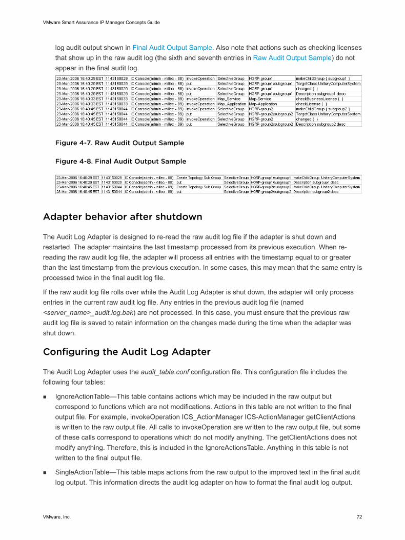
log audit output shown in Final Audit Output Sample. Also note that actions such as checking licensesthat show up in the raw audit log (the sixth and seventh entries in Raw Audit Output Sample) do notappear in the final audit log.
Figure 4-7. Raw Audit Output Sample
Figure 4-8. Final Audit Output Sample
Adapter behavior after shutdown
The Audit Log Adapter is designed to re-read the raw audit log file if the adapter is shut down andrestarted. The adapter maintains the last timestamp processed from its previous execution. When re-reading the raw audit log file, the adapter will process all entries with the timestamp equal to or greaterthan the last timestamp from the previous execution. In some cases, this may mean that the same entry isprocessed twice in the final audit log file.
If the raw audit log file rolls over while the Audit Log Adapter is shut down, the adapter will only processentries in the current raw audit log file. Any entries in the previous audit log file (named<server_name>_audit.log.bak) are not processed. In this case, you must ensure that the previous rawaudit log file is saved to retain information on the changes made during the time when the adapter wasshut down.
Configuring the Audit Log Adapter
The Audit Log Adapter uses the audit_table.conf configuration file. This configuration file includes thefollowing four tables:
n IgnoreActionTable—This table contains actions which may be included in the raw output butcorrespond to functions which are not modifications. Actions in this table are not written to the finaloutput file. For example, invokeOperation ICS_ActionManager ICS-ActionManager getClientActionsis written to the raw output file. All calls to invokeOperation are written to the raw output file, but someof these calls correspond to operations which do not modify anything. The getClientActions does notmodify anything. Therefore, this is included in the IgnoreActionsTable. Anything in this table is notwritten to the final output file.
n SingleActionTable—This table maps actions from the raw output to the improved text in the final auditlog output. This information directs the audit log adapter on how to format the final audit log output.
VMware Smart Assurance IP Manager Concepts Guide
VMware, Inc. 72
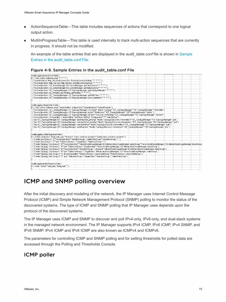
n ActionSequenceTable—This table includes sequences of actions that correspond to one logicaloutput action.
n MultiInProgressTable—This table is used internally to track multi-action sequences that are currentlyin progress. It should not be modified.
An example of the table entries that are displayed in the audit_table.conf file is shown in SampleEntries in the audit_table.conf File.
Figure 4-9. Sample Entries in the audit_table.conf File
ICMP and SNMP polling overview
After the initial discovery and modeling of the network, the IP Manager uses Internet Control MessageProtocol (ICMP) and Simple Network Management Protocol (SNMP) polling to monitor the status of thediscovered systems. The type of ICMP and SNMP polling that IP Manager uses depends upon theprotocol of the discovered systems.
The IP Manager uses ICMP and SNMP to discover and poll IPv4-only, IPv6-only, and dual-stack systemsin the managed network environment. The IP Manager supports IPv4 ICMP, IPv6 ICMP, IPv4 SNMP, andIPv6 SNMP. IPv4 ICMP and IPv6 ICMP are also known as ICMPv4 and ICMPv6.
The parameters for controlling ICMP and SNMP polling and for setting thresholds for polled data areaccessed through the Polling and Thresholds Console.
ICMP poller
VMware Smart Assurance IP Manager Concepts Guide
VMware, Inc. 73
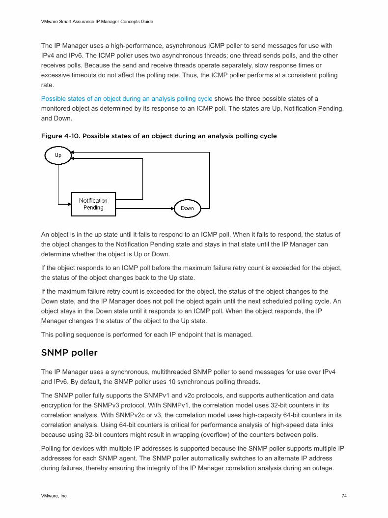
The IP Manager uses a high-performance, asynchronous ICMP poller to send messages for use withIPv4 and IPv6. The ICMP poller uses two asynchronous threads; one thread sends polls, and the otherreceives polls. Because the send and receive threads operate separately, slow response times orexcessive timeouts do not affect the polling rate. Thus, the ICMP poller performs at a consistent pollingrate.
Possible states of an object during an analysis polling cycle shows the three possible states of amonitored object as determined by its response to an ICMP poll. The states are Up, Notification Pending,and Down.
Figure 4-10. Possible states of an object during an analysis polling cycle
An object is in the up state until it fails to respond to an ICMP poll. When it fails to respond, the status ofthe object changes to the Notification Pending state and stays in that state until the IP Manager candetermine whether the object is Up or Down.
If the object responds to an ICMP poll before the maximum failure retry count is exceeded for the object,the status of the object changes back to the Up state.
If the maximum failure retry count is exceeded for the object, the status of the object changes to theDown state, and the IP Manager does not poll the object again until the next scheduled polling cycle. Anobject stays in the Down state until it responds to an ICMP poll. When the object responds, the IPManager changes the status of the object to the Up state.
This polling sequence is performed for each IP endpoint that is managed.
SNMP poller
The IP Manager uses a synchronous, multithreaded SNMP poller to send messages for use over IPv4and IPv6. By default, the SNMP poller uses 10 synchronous polling threads.
The SNMP poller fully supports the SNMPv1 and v2c protocols, and supports authentication and dataencryption for the SNMPv3 protocol. With SNMPv1, the correlation model uses 32-bit counters in itscorrelation analysis. With SNMPv2c or v3, the correlation model uses high-capacity 64-bit counters in itscorrelation analysis. Using 64-bit counters is critical for performance analysis of high-speed data linksbecause using 32-bit counters might result in wrapping (overflow) of the counters between polls.
Polling for devices with multiple IP addresses is supported because the SNMP poller supports multiple IPaddresses for each SNMP agent. The SNMP poller automatically switches to an alternate IP addressduring failures, thereby ensuring the integrity of the IP Manager correlation analysis during an outage.
VMware Smart Assurance IP Manager Concepts Guide
VMware, Inc. 74
Just-in-time polling
The SNMP poller’s MIB variable poll list is driven by a Just-In-Time polling algorithm, which ensures thatonly those MIB variables needed for correlation are polled. For example, if a port monitored forperformance data is disabled, or goes down, the SNMP poller automatically removes the relevant MIBvariables from the poll list. If the port is reenabled, or comes back up, the variables are automatically putback onto the MIB poll list.
Request-consolidation polling
Issuing a single SNMP GET request that requests 10 variables is more efficient than issuing 10 GETrequests each requesting a single variable. The SNMP poller consolidates as many variables as possibleinto a single SNMP GET request. The consolidation is not restricted to variables from the same SNMPtable. Polling consolidation continually adapts to changes in the MIB variable poll list.
Upon encountering a nonfatal error during polling consolidation, the SNMP poller responds differently toan SNMPv1 agent than to an SNMPv2c or v3 agent for the following reason: Where an SNMPv1 agentstops processing a request upon encountering an error, an SNMPv2c or v3 agent continues processing arequest upon encountering an error. An SNMPv2c or v3 agent handles errors on a per-OID basis.
If a nonfatal error is encountered by an SNMPv1 agent during a GET request seeking multiple variables,the SNMP poller suspends the polling of the affected variable. It suspends polling to prevent reducedperformance of the SNMPv1 agent, since continuous polling of the affected variable would require theresending of the remainder of the request after receiving the error. The SNMP poller continues to poll theunaffected variables. (An example of an affected variable is one that has become unavailable due to aconfiguration change.) This behavior enables the SNMP poller to operate efficiently with an SNMPv1agent during unexpected changes to a device’s configuration.
In contrast, if a nonfatal error is encountered by an SNMPv2c or v3 agent during a GET request seekingmultiple variables, the SNMP poller continues the polling of the affected variable as well as the unaffectedvariables.
ICMP and SNMP polling coordination
The IP Manager links its ICMP and SNMP pollers so that the SNMP poller does not send requests to anySNMP agent address that the ICMP poller determines to be unreachable. IP addresses that areunresponsive to ICMP polls are added to a “do not poll” list, which the SNMP poller checks beforesending SNMP requests.
The checking process is as follows:
n If an SNMP agent address is on the “do not poll” list, the SNMP poller does not send a request to thataddress.
n If an SNMP agent has multiple IP addresses, the SNMP poller checks for each address in the “do notpoll” list.
n For an address that does not appear in the list, the SNMP poller sends a request to that address.
VMware Smart Assurance IP Manager Concepts Guide
VMware, Inc. 75
n If all addresses for an agent are on the list, the SNMP poller deems the agent as unreachableand temporarily suspends sending SNMP requests to that agent.
As soon as an agent’s IP address becomes responsive, as determined by the ICMP poller, theaddress is removed from the list, and SNMP polling resumes.
Federal Information Processing Standard (FIPS) 140
The Federal Information Processing Standard (FIPS) Publication 140-2 is a U.S. government computersecurity standard governing cryptographic modules and is required for any software purchased by the USgovernment and US military.
Open-source derived cryptographic algorithms implemented in DMT's C/C++ code base were removedand replaced with RSA's BSAFE Micro Edition Suite (MES).
RSA’s BSAFE MES is a library that implements algorithms and provides both FIPS-validated and non-FIPS implementations of the cryptographic algorithms. The non-FIPS implementations are used bydefault. When placed in FIPS 140 mode, DMT causes MES to use the FIPS 140 validatedimplementations.
FIPS 140 mode allows you to use only SNMPv1, SNMPv2c, and SNMPv3 except MD5 and DESauthentication protocols. If you run SNMPv1 or SNMPv2c, then FIPS 140 mode has no impact. If you areusing encryption, then you must use a certified encryption library and only certain encryption routines.
When you discover an SNMPv3 device, you need to select the option “V3” in the “Add Agent” window.The “Authentication Protocol” option lists only SHA and not MD5 and the “Privacy Protocol” option listsonly AES and not DES. This is because MD5 and DES are not supported in FIPS 140 mode. If youdiscover SNMPv3 devices with MD5 and DES protocol as seed, discovery fails and the devices go to thePending List and display as “Invalid” or “Unsupported SNMP V3 protocol”. ASL error exception messagesare also observed in the IP server logs.
“Support for FIPS 140-2 in IP 9.1” section in Chapter 3, Installing IP Manager, in the VMware SmartAssurance Installation Guide for SAM, IP, ESM, MPLS, and NPM Managers, provides more informationabout the FIPS 140 mode implementation.
VMware Smart Assurance IP Manager Concepts Guide
VMware, Inc. 76
Discovery 5This chapter includes the following topics:
n Discovery process overview
n Network system support
n Light discovery
n ICMP, SNMP, ASNMP, and IPv6 support
n Support for HSRP and VRRP groups
n Support for NAS gateways
n Support for NIC teaming
n Support for IPSec and IKE tunnels
n Support for overlapping IP addresses
n Support for SNMP v3 auto discovery
n Support for Wireless LAN
n Support for Virtual Port Channel
n Link Aggregation and EtherChannel discovery
n Support for Virtual Data Context
n DASL integration
n Virtual bridging
n Incremental reconfigure
n Default IP route
n Asynchronous SNMP (ASNMP)
n Link Layer Discovery Protocol (LLDP)
n Unique VLAN naming
n OID Info Tool
n ESX Server Certification
n Cisco Nexus 1000V implementation
n Cisco Unified Computing System Certification
VMware, Inc. 77

n AggregateLink representation in the Map console
n Discovery and the VPN-Tagging Server
n About seed files
n Seed file format
n Seed file examples
n Which systems to put in a seed file
n Discovery methods
n Discovery phases
n Autodiscovery data sources
n Discovery of NIC teaming
n Discovery and short discovery of IPSec tunnels
n Discovery and the local name resolution service
n Hostname resolution and IP address checking
n How discovery names a system
n Configuring automatic name resolution
n Preparing for manual discovery
n Initiating manual or autodiscovery
n Initiating postprocessing
n About discovery filters
n Discovery filter fields
n Discovery filter considerations
n Discovery filter matching
n Examples of discovery filters
n Discovery results
n Discovery error scenarios and results
n Discovery errors
n DiscoveryError notifications
n Pending Devices list
n About certifying managed devices
n Discovery hook scripts
n Automatic and manual discovery
n Discovery methods
VMware Smart Assurance IP Manager Concepts Guide
VMware, Inc. 78
n Discovery considerations
n Scheduling automatic discovery
n Read community strings
n About managing and unmanaging topology objects
n Handling duplicate IP address errors
n Redundancy groups
n ICMP
n SNMP
n About ICMP and SNMP polling parameters
Discovery process overview
During per-device discovery, the IP Manager sends ICMP and SNMP polls to the network devices todiscover the network topology. The IP Manager uses VMware Smart Assurance object classes to create adata-model representation of the discovered topology. The data model includes representations of themanaged network devices and their internal components.
During postprocessing, the IP Manager uses VMware Smart Assurance object classes to createrepresentations of the physical and logical connections between the managed network devices. The IPManager also establishes device relationships.
The data model that is supported by the IP Manager is described in the VMware Smart Assurance IPManager Reference Guide
Note Throughout this chapter and the chapters that follow, the terms “system” and “device” are usedinterchangeably. Usually, “system” is used.
The configurations and licenses that are applied to an IP Manager at startup determine which discoveryand analysis will run. By default, discovery and analysis for both IP Availability Manager and IPPerformance Manager will run.
“Components of a typical IP Manager deployment” on page 36 identifies the elements of a typical IPManager deployment and shows the flow of information among the elements.
The IP Manager discovers Layer 2 (data link) and Layer 3 (network) connectivity in multivendor, switched,and routed networks. Layer 2 network systems use machine addresses to transmit packets from networknode to network node, and Layer 3 network systems use network addresses to route data to differentLANs and WANs. The IP Manager discovers the network systems by sending them ICMP and SNMPpolls.
In addition, depending on the configuration, IP Availability Manager also sends network topology to theVMware Smart Assurance Service Assurance Manager Adapter Platform (Adapter Platform) and tosatellite Domain Managers.
VMware Smart Assurance IP Manager Concepts Guide
VMware, Inc. 79
Running separate instances of IP Availability Manager and IP Performance Manager is necessary if thetwo applications are running on different hosts. When running on the same host, a more commonconfiguration would be IP Availability Manager and IP Performance Manager running as a single process.
After building a data model of the discovered network topology, IP Availability Manager, IP PerformanceManager, and IP Server Performance Manager use SNMP polling to monitor the topology. The results ofthis polling, in conjunction with the received SNMP traps, are used by:
n IP Availability Manager to diagnose the failed network objects that interrupt network connectivity.
n IP Performance Manager and IP Server Performance Manager to diagnose emerging problems in theservice delivery infrastructure.
IP Availability Manager, IP Performance Manager, and IP Server Performance Manager export theirtopology data and analysis results (events) to the VMware Smart Assurance Service AssuranceManager (Global Manager).
Whenever discovery completes, the IP Manager prints a report to its log file identifying the number ofnetwork objects that are created during the discovery. Naming of the log depends on the locale andencoding set by the user and is controlled by the SM_LOCALE and SM_ENCODING environmentvariables. The log file is named <IP Manager instance name>_<locale>_<character encoding>.log(for example, INCHARGE-AM_en_US_UTF-8.log) and is located in the BASEDIR/smarts/local/logsdirectory in the IP Manager installation area.
Network system support
The IP Manager discovers and models the following types of network systems:
n Bridges
n Hosts
n Hubs
n Nodes
n Probes
n Routers
n Switches
n Terminal servers
The VMware Smart Assurance IP Manager Reference Guide provides information about the classesthat are used by the IP Manager to model these systems.
Fully tested devices
VMware Smart Assurance IP Manager Concepts Guide
VMware, Inc. 80
The IP Manager supports the discovery, monitoring, and analysis of IP networks in many vendor-specificenvironments. The VMware Smart Assurance IP Certification Matrix identifies the devices that have beenfully tested for this release of IP Manager. This document is found on VMware Online Support at:docs.vmware.com.
Routing-device types
The following routing-device types are supported by the IP Manager:
n Physical routers
n Virtual routers
n Route switch modules (RSMs)
n Route switch feature cards (RSFCs)
n Multilayer switch feature cards (MSFCs)
Virtual routers are implemented within physical routers or switches.
RSMs, RSFCs, and MSFCs are routing-device type cards in Layer 3 (network) switches. The cardsperform routing between virtual LANs (VLANs).
Layer 3 switch devices that house routing-device type cards are called hybrids.
Light discovery
In addition to performing its traditional discovery of network objects, the IP Manager, as shown inExporting topology collection sets to satellite Domain Managers, can be configured to create topologycollection sets from the discovered network objects, one set for each of the satellite Domain Managersthat are supported by the IP Manager. The creation of topology collection sets is known as “IP Managerlight discovery” or simply “light discovery.”
VMware Smart Assurance IP Manager Concepts Guide
VMware, Inc. 81
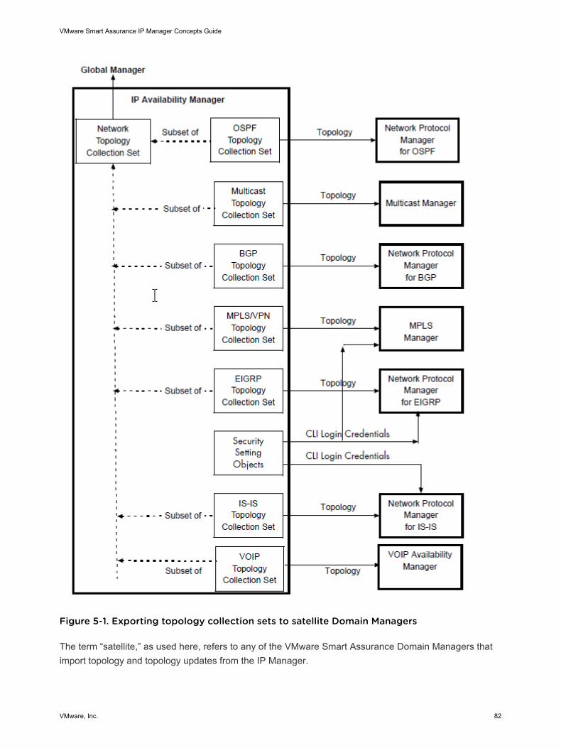
Figure 5-1. Exporting topology collection sets to satellite Domain Managers
The term “satellite,” as used here, refers to any of the VMware Smart Assurance Domain Managers thatimport topology and topology updates from the IP Manager.
VMware Smart Assurance IP Manager Concepts Guide
VMware, Inc. 82
Topology import
From the IP Manager, a satellite Domain Manager not only receives its initial topology and subsequenttopology updates, but it also receives Layer 1 (physical) and Layer 2 (data link) status updates that arerelevant to the imported topology. As an example of the types of objects that are imported from the IPManager, Network Protocol Manager for EIGRP imports router and switch objects along with the followingobjects that are associated with the routers or switches:
n Card
n Interface
n NetworkConnection
n Cable
n TrunkCable
n IP
n DuplicateIP
n IPNetwork
n SNMPAgent
n VRAgent
Note The indentations in the bullet list indicate class hierarchy. The VMware Smart AssuranceIP Manager Reference Guide provides descriptions of these object types.
Although all satellite Domain Managers import topology and topology updates from the IPManager, not all import topology collection sets. That is, some satellite Domain Managers use ameans other than light discovery to import topology and topology updates from the IP Manager.The individual configuration guides for the satellite Domain Managers state which DomainManagers import topology collection sets.
By default, light discovery is disabled.
The VMware Smart Assurance IP Manager User Guide provides instructions on configuring theIP Manager to create topology collection sets.
CLI device-access object import
Network Protocol Manager for EIGRP, Network Protocol Manager for IS-IS, and Multiprotocol LabelSwitching (MPLS Manager) also import one or more of the following types of CLI device-access objectsfrom the IP Manager:
n Configuration
n ICF_Criteria
n SelectiveConfiguration
VMware Smart Assurance IP Manager Concepts Guide
VMware, Inc. 83
n CLI_AccessSetting
n ICF_ConfigurationSelector
The CLI device-access objects carry the login credentials and other criteria that are needed by asatellite Domain Manager to access devices in the managed network for the purpose of invoking CLIcommands from the devices.
The VMware Smart Assurance IP Manager User Guide provides information about creating CLIdevice-access objects.
ICMP, SNMP, ASNMP, and IPv6 support
The IP Manager uses Internet Control Message Protocol (ICMP) and Simple Network ManagementProtocol (SNMP) to discover IPv4-only, IPv6-only, and dual-stack systems in the managed networkenvironment. A dual-stack system is configured with both IPv4 (32-bit) and IPv6 (128-bit) addresses.
The IP Manager supports IPv4 ICMP (also known as ICMPv4), IPv6 ICMP (also known as ICMPv6), IPv4SNMP, and IPv6 SNMP. Because many Management Information Bases (MIBs) have not yet beenmodified to accommodate IPv6 addresses, certain IP Manager features are not available to IPv6.
Note Starting from IP 8.1.1, IPv6 addresses on a device that are link-local (FE80::), site-local (FEC0::),multicast (FF00::), or loopback (::1) do not get discovered and are not added to the topology. Forexample, a valid link-local IPv6 address FE80:0:0:0:20F:35FF:FEC1:2400, will not be discovered.
The IP Manager also supports SNMPv1, v2c, and v3.
The VMware Smart Assurance IP Manager User Guide provides information about ICMP, SNMP, andAsynchronous SNMP (ASNMP). Unless specified otherwise, the term ICMP is used to refer to IPv4 andIPv6 ICMP polling, and the term SNMP is used to refer to IPv4 and IPv6 SNMP polling.
Support for HSRP and VRRP groups
The IP Manager is able to discover and monitor redundancy groups of routers that are involved in HotStandby Router Protocol (HSRP) or Virtual Router Redundancy Protocol (VRRP) groups. It discoversHSRP groups, HSRP router endpoints, VRRP groups, and VRRP router endpoints, and represents themas instances of the HSRPGroup, HSRPEndpoint, VRRPGroup, and VRRPEndpoint classes, respectively.
The VMware Smart Assurance IP Manager Reference Guide provides descriptions of these object types.
Support for NAS gateways
The IP Manager discovers and monitors VMware Celerra network-attached storage (NAS) gateways andNAS connectivity problems. It discovers NAS chassis, Control Stations, and Data Movers, and representsthem as instances of the NASChassis, Host, and FileServer classes, respectively.
VMware Smart Assurance IP Manager Concepts Guide
VMware, Inc. 84
In IP 9.2, once the Control Station is discovered, by default, it will automatically move the File serversattached to it to the Pending List.
Note Monitoring of File System of File Servers and DataMovers are not supported.
The VMware Smart Assurance IP Manager Reference Guide provides descriptions of these object types.
Support for NIC teaming
The IP Manager discovers and monitors network interface card (NIC) teaming between hosts andswitches. NIC teaming is the grouping of two or more physical NICs into a single logical NIC, for thepurpose of achieving network fault tolerance or network traffic load balancing or both. NIC teaming isdescribed in Discovery of NIC teaming.
Note Setting up NIC teaming is device and vendor specific. Vendor specific documentation on how toset it up in a customer environment with different vendors is not provided in the manuals. For any deviceor vendor specific setup information, it is recommended to refer to the relevant vendor specificdocumentation.
Support for IPSec and IKE tunnels
The IP Manager is able to discover and monitor IPSec tunnels and Internet Key Exchange (IKE) tunnelsbetween IPSec-enabled routers on IPv4 networks. IPSec is a standardized framework for securing IPcommunications at the network layer, and IKE is a standardized key exchange protocol that is used to setup IPSec tunnels. Tunnel discovery is described in Discovery and short discovery of IPSec tunnels.
Support for overlapping IP addresses
The IP Manager is able to discover and create tagged IP objects for overlapping IPv4 addresses, whichare IP addresses that are reused and configured across multiple network devices in the same managednetwork environment.
The VMware Smart Assurance IP Manager User Guide describes the IP tagging feature and providesinstructions on configuring IP tagging and creating IP tag filters. The VMware Smart Assurance IPManager Reference Guide identifies the configuration parameters that control IP tagging.
Support for SNMP v3 auto discovery
IP Manager has been enhanced to support auto discovery of devices in an IP network using SNMP v3polling mechanism. With the support for SNMP v3 polling mechanism, you can discover and monitorthose devices in the network that supports SNMP v3. This has been facilitated by the following changesin the IP Domain Manager Administration Console user interface:
n Enhancement to Discovery Filters tab
VMware Smart Assurance IP Manager Concepts Guide
VMware, Inc. 85
n Enhancement to Topology tab
n Supported Encryption Standards
The VMware Smart Assurance IP Manager User Guide provides more information on the aboveenhancements including supported encryption standards.
Support for Wireless LAN
IP supports discovery and monitoring a wireless LAN. As part of wireless LAN discovery and monitoring,IP discovers Wireless Controllers, WirelessAccessPoints, Wireless Clients and Authentication server. Anauthentication server provides authentication service for different network elements such as WirelessClients.
The VMware Smart Assurance IP Manager Reference Guide provides more information on topologyclasses and root-case analysis scenarios for Wireless LAN.
The Wireless certification is currently supported for two vendors, namely Cisco and Aruba. Thecertification of the two vendors can be found in the following conf files:
n oid2Type_Cisco.conf in <BASEDIR>\IP\smarts\conf\discovery
n oid2Type_Aruba.conf in <BASEDIR>\IP\smarts\conf\discovery
Note IP server does not generate any alert if the status of the authentication server is UNKNOWN.So, if the WirelessController is Down, the related authentication server status is UNKNOWN.Therefore, to get the proper status of the authentication server, rediscover any other runningWirelessContoller that is serviced by the same authentication server.
Wireless LAN short discovery
Short discovery handles wireless topology changes, which typically occur during WirelessClientmovement. In addition, it dynamically detects Rogue Wireless Access Points.
Wireless LAN settings lists the flags that determine the settings for Wireless LAN discovery.
VMware Smart Assurance IP Manager Concepts Guide
VMware, Inc. 86
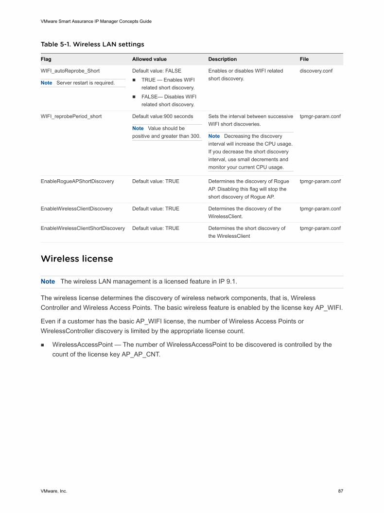
Table 5-1. Wireless LAN settings
Flag Allowed value Description File
WIFI_autoReprobe_Short
Note Server restart is required.
Default value: FALSE
n TRUE — Enables WIFIrelated short discovery.
n FALSE— Disables WIFIrelated short discovery.
Enables or disables WIFI relatedshort discovery.
discovery.conf
WIFI_reprobePeriod_short Default value:900 seconds
Note Value should bepositive and greater than 300.
Sets the interval between successiveWIFI short discoveries.
Note Decreasing the discoveryinterval will increase the CPU usage.If you decrease the short discoveryinterval, use small decrements andmonitor your current CPU usage.
tpmgr-param.conf
EnableRogueAPShortDiscovery Default value: TRUE Determines the discovery of RogueAP. Disabling this flag will stop theshort discovery of Rogue AP.
tpmgr-param.conf
EnableWirelessClientDiscovery Default value: TRUE Determines the discovery of theWirelessClient.
tpmgr-param.conf
EnableWirelessClientShortDiscovery Default value: TRUE Determines the short discovery ofthe WirelessClient
tpmgr-param.conf
Wireless license
Note The wireless LAN management is a licensed feature in IP 9.1.
The wireless license determines the discovery of wireless network components, that is, WirelessController and Wireless Access Points. The basic wireless feature is enabled by the license key AP_WIFI.
Even if a customer has the basic AP_WIFI license, the number of Wireless Access Points orWirelessController discovery is limited by the appropriate license count.
n WirelessAccessPoint — The number of WirelessAccessPoint to be discovered is controlled by thecount of the license key AP_AP_CNT.
VMware Smart Assurance IP Manager Concepts Guide
VMware, Inc. 87
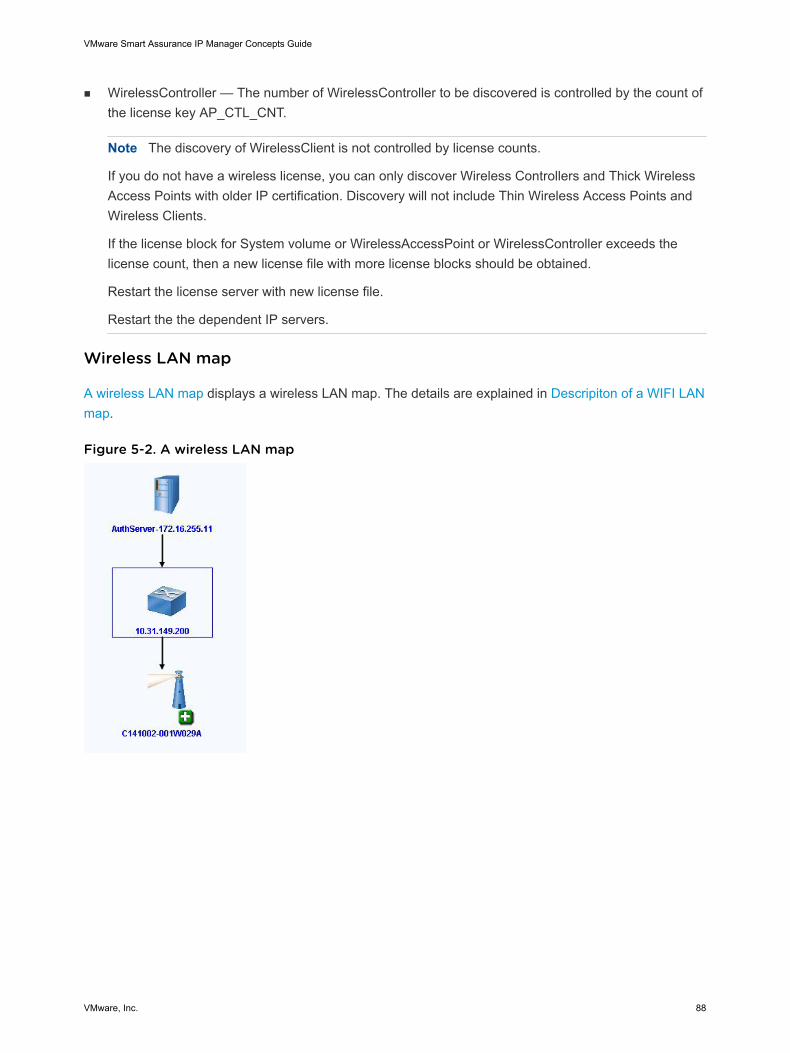
n WirelessController — The number of WirelessController to be discovered is controlled by the count ofthe license key AP_CTL_CNT.
Note The discovery of WirelessClient is not controlled by license counts.
If you do not have a wireless license, you can only discover Wireless Controllers and Thick WirelessAccess Points with older IP certification. Discovery will not include Thin Wireless Access Points andWireless Clients.
If the license block for System volume or WirelessAccessPoint or WirelessController exceeds thelicense count, then a new license file with more license blocks should be obtained.
Restart the license server with new license file.
Restart the the dependent IP servers.
Wireless LAN map
A wireless LAN map displays a wireless LAN map. The details are explained in Descripiton of a WIFI LANmap.
Figure 5-2. A wireless LAN map
VMware Smart Assurance IP Manager Concepts Guide
VMware, Inc. 88
Table 5-2. Descripiton of a WIFI LAN map
Icons Representation Relationships
WirelessAccessPoint n ControlledBy relationship with WirelessController
n Hosts relationship with WirelessClients
Note Click on the + icon to view the WirelessClients that are hosted by thisWirelessAccessPoint.
WirelessController n Controls relationship with WirelessAccessPoint
n HostsStations relationship with WirelessClient
AuthenticationServer AuthenticationServiceTo relationship with the WirelessController.
Support for Virtual Port Channel
IP 9.1 supports Virtual Port Channel (vPC) management on Cisco Nexus 5000 switches. A Virtual PortChannel is formed by the logical aggregation of ethernet switch ports that belong to two differentswitches.
The Virtual Port Channel is represented as vAggregatePort in IP topology.
Note IP 9.1 supports vPC on Cisco Nexus 5000 switches through CLI discovery. Provide read-onlycredentials of the Cisco Nexus 5000 switch in CLI Access Group with matching criteria in Polling andThreshold console > Device Access.
The vAggregatePort class is defined by the following relationships:
n LayeredOver/Underlying relationship with Switches.
n ComposedOf/PartOf relationship with underlying AggregatePorts (vPC member ports).
n Uses/UsedBy relationship with AggregatePorts participating in peer link.
Enabling vPC discovery
The flag EnableVPCDiscovery controls vPC discovery. By default, vPC discovery is enabled in IP 9.1.
To disable vPC discovery, set the value of the flag EnableVPCDiscovery in <BASEDIR>/conf/tpmgr-param.conf file.
EnableVPCDiscovery= FALSE
For information on the events and root-cause analysis of vAggregatePort, refer to VMware SmartAssurance IP Manager Reference Guide.
VMware Smart Assurance IP Manager Concepts Guide
VMware, Inc. 89
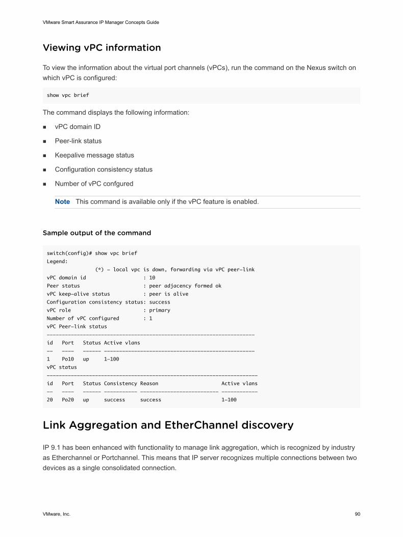
Viewing vPC information
To view the information about the virtual port channels (vPCs), run the command on the Nexus switch onwhich vPC is configured:
show vpc brief
The command displays the following information:
n vPC domain ID
n Peer-link status
n Keepalive message status
n Configuration consistency status
n Number of vPC confgured
Note This command is available only if the vPC feature is enabled.
Sample output of the command
switch(config)# show vpc brief
Legend:
(*) - local vpc is down, forwarding via vPC peer-link
vPC domain id : 10
Peer status : peer adjacency formed ok
vPC keep-alive status : peer is alive
Configuration consistency status: success
vPC role : primary
Number of vPC configured : 1
vPC Peer-link status
---------------------------------------------------------------------
id Port Status Active vlans
-- ---- ------ --------------------------------------------------
1 Po10 up 1-100
vPC status
----------------------------------------------------------------------
id Port Status Consistency Reason Active vlans
-- ---- ------ ----------- -------------------------- ------------
20 Po20 up success success 1-100
Link Aggregation and EtherChannel discovery
IP 9.1 has been enhanced with functionality to manage link aggregation, which is recognized by industryas Etherchannel or Portchannel. This means that IP server recognizes multiple connections between twodevices as a single consolidated connection.
VMware Smart Assurance IP Manager Concepts Guide
VMware, Inc. 90
Link Aggregation allows one or more ports to be aggregated together to form a Link Aggregation Group(LAG), such that a MAC Client can treat the Link Aggregation Group as if it were a single link.
Note Link Aggregation Group (LAG) discovery is supported on Cisco Nexus 5000 switches through CLIdiscovery. LAG can be formed using LACP / PAGP (Cisco proprietary) signalling protocol. Both LACP andPAGP protocols are supported by IP.
This feature allows:
n Detection of failure of logical groups. When there is a signal failure or a failure in all of the discreteconnections, then a single Down problem is reported on the LAG.
n Discovery of peer port connectivity and Logical Group connectivity in Cisco devices.
Note This is true even when the neighbor discovery protocol is not enabled.
n Detection of traffic load imbalance among ports that participate in an aggregation. Generates theevent UnbalancedAdapterUtilization for AggregatePort when traffic load is relatively imbalanced.
n Chapter 1 in VMware Smart Assurance IP Manager Reference Guide provides more information onhow the this event is calculated.
Representation of Etherchannel
The discovered etherchannel connections are represented by the following classes:
n AggregatePort — This class represents the etherchannel adapter in IP Availability Manager. It isdefined as the logical grouping of network adapters.
n AggregateLink — This class represents the logical links between AggregatePorts. During postprocessing, all the AggregatePorts instances are retrieved from the discovered topology. If theconstituents ports of the AggregatePort are connected and the peer ports of those constituent portsare associated with AggregatePort, then AggregateLink is created between those two AggregatePort.
The VMware Smart Assurance IP Manager Reference Guide and the VMware Smart Assurance IPManager Release Notes provide more information.
Identifying AggregationPorts through CLI
You can identify AggregatePorts and figure out ports that are part of an aggregation by running the CLIcommand:
show port-channel summary
Chapter 3 in VMware Smart Assurance IP Manager User Guide provides more information.
Support for Virtual Data Context
VMware Smart Assurance IP Manager Concepts Guide
VMware, Inc. 91
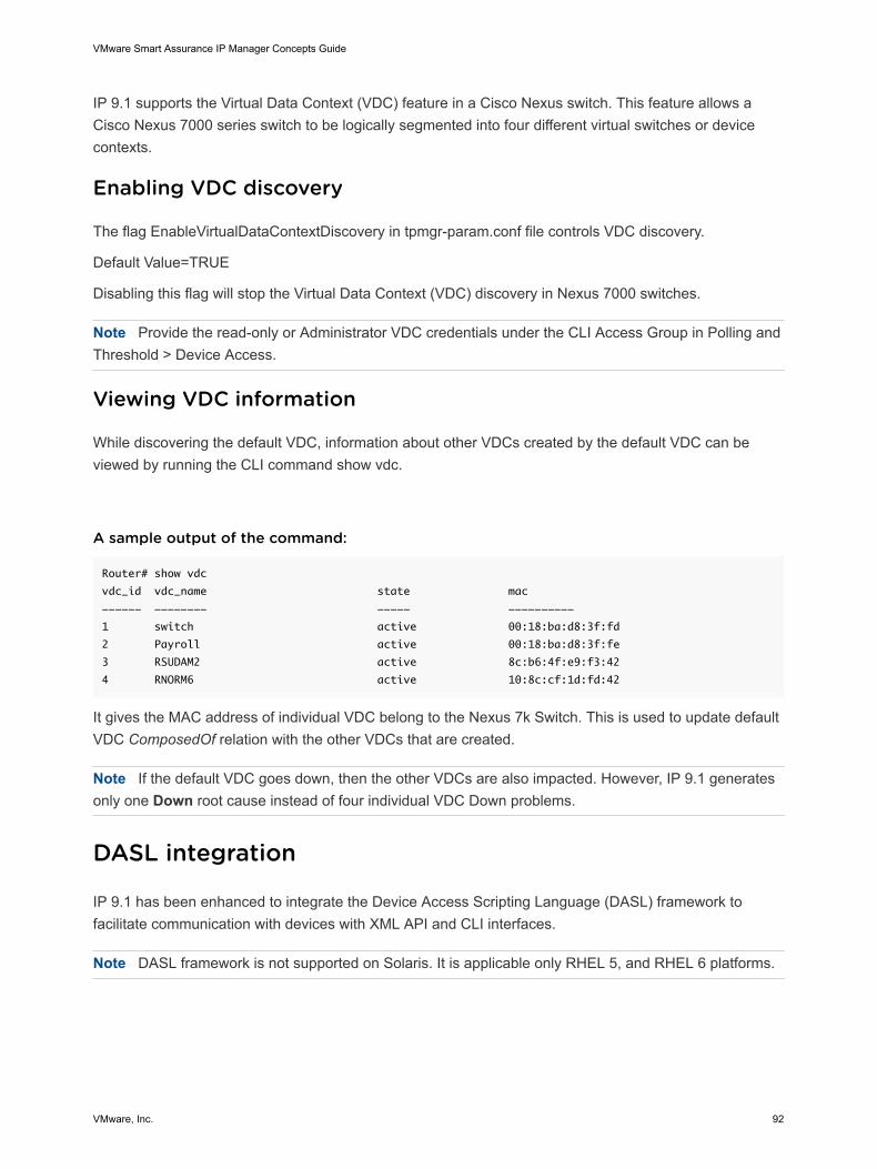
IP 9.1 supports the Virtual Data Context (VDC) feature in a Cisco Nexus switch. This feature allows aCisco Nexus 7000 series switch to be logically segmented into four different virtual switches or devicecontexts.
Enabling VDC discovery
The flag EnableVirtualDataContextDiscovery in tpmgr-param.conf file controls VDC discovery.
Default Value=TRUE
Disabling this flag will stop the Virtual Data Context (VDC) discovery in Nexus 7000 switches.
Note Provide the read-only or Administrator VDC credentials under the CLI Access Group in Polling andThreshold > Device Access.
Viewing VDC information
While discovering the default VDC, information about other VDCs created by the default VDC can beviewed by running the CLI command show vdc.
A sample output of the command:
Router# show vdc
vdc_id vdc_name state mac
------ -------- ----- ----------
1 switch active 00:18:ba:d8:3f:fd
2 Payroll active 00:18:ba:d8:3f:fe
3 RSUDAM2 active 8c:b6:4f:e9:f3:42
4 RNORM6 active 10:8c:cf:1d:fd:42
It gives the MAC address of individual VDC belong to the Nexus 7k Switch. This is used to update defaultVDC ComposedOf relation with the other VDCs that are created.
Note If the default VDC goes down, then the other VDCs are also impacted. However, IP 9.1 generatesonly one Down root cause instead of four individual VDC Down problems.
DASL integration
IP 9.1 has been enhanced to integrate the Device Access Scripting Language (DASL) framework tofacilitate communication with devices with XML API and CLI interfaces.
Note DASL framework is not supported on Solaris. It is applicable only RHEL 5, and RHEL 6 platforms.
VMware Smart Assurance IP Manager Concepts Guide
VMware, Inc. 92
DASL is used for creating device-independent access methods. DASL framework integration allows IP toprovide multiple-vendor support quickly and easily. It is designed to encapsulate all device-specificinformation in a highly modifiable manner, allowing the main products to remain device-independent. Theaccess methods include:
n Telnet
n SSH
n HTTP
n HTTPS
CLI interface
The CLI framework provides IP server the capability to communicate with devices with CLI interfaces. Forall communications with the corresponding devices, it uses Telnet or SSH. The devices could be anyUnitaryComputerSystem with Telnet or SSH enabled. The commands are executed on the devices as lineby line text, and the response processed as required in the IP server. The framework provides anexcellent means of session caching as it improves performance by avoiding the building up of connectionevery time.
Prerequisites:
n The devices should be certified.
n Configure device access credential in the group CLI Access Group in IP Domain ManagerAdministrator > Polling and Threshold > Device Access tab as shown in #unique_153/unique_153_Connect_42__IP_CONCEPTS_DISCOVERY_10487.
New features using CLI
DASL CLI is used for LAG discovery on Nexus 5000, Nexus 6000, and Nexus 7000 switches. It is alsoused for VPC discovery on Nexus 5000 and VDC discovery on Nexus 7000.
Note In the 9.1 release, DASL CLI is used only for discovery and not for monitoring.
XML interface
The XML framework of DASL provides IP Server the capability to communicate with and manage deviceswhich expose XML interfaces. XML data are exchanged between the IP server and the correspondingdevices using HTTP/HTTPS and by executing GET/POST commands.
Note In the 9.1 release, only the XML framework is available and is not used for implementing anyfeature.
Prerequisites:
n The device should be certified.
n An XML driver should be associated with it.
VMware Smart Assurance IP Manager Concepts Guide
VMware, Inc. 93
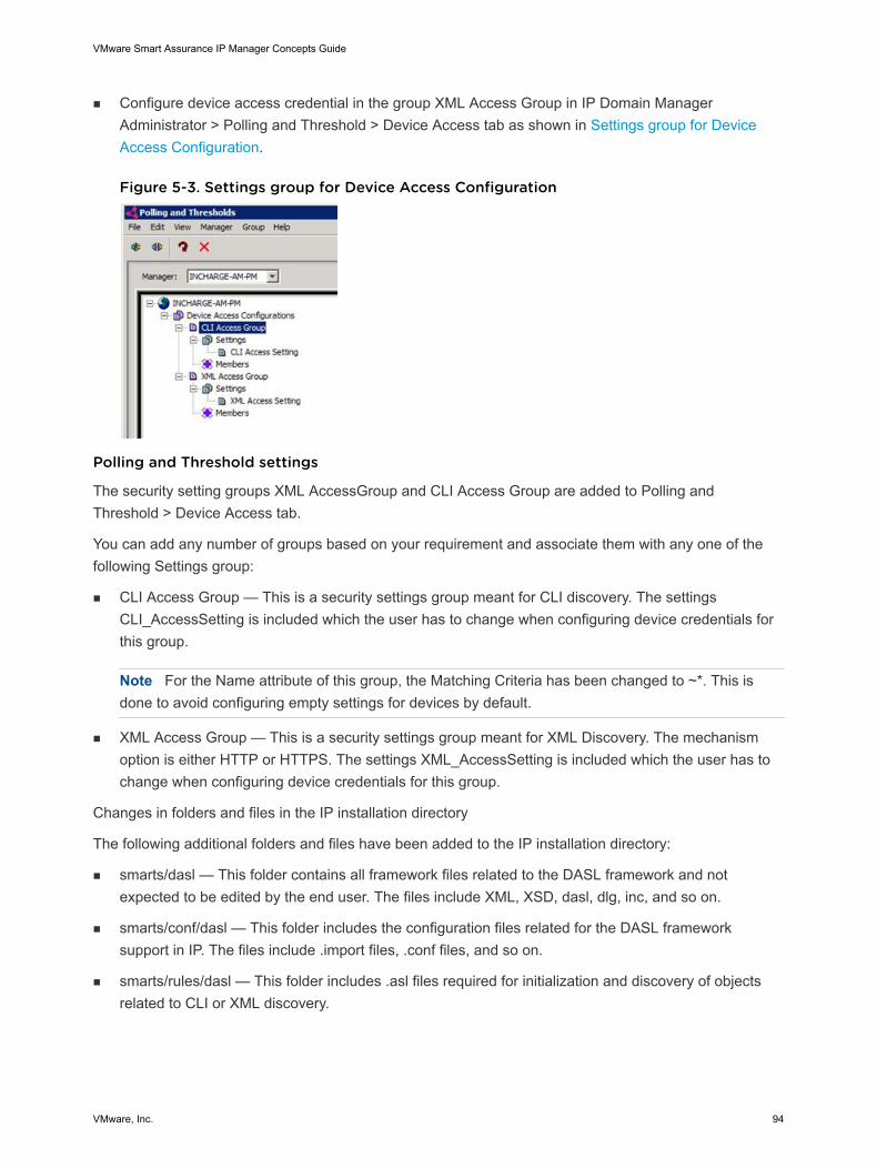
n Configure device access credential in the group XML Access Group in IP Domain ManagerAdministrator > Polling and Threshold > Device Access tab as shown in Settings group for DeviceAccess Configuration.
Figure 5-3. Settings group for Device Access Configuration
Polling and Threshold settings
The security setting groups XML AccessGroup and CLI Access Group are added to Polling andThreshold > Device Access tab.
You can add any number of groups based on your requirement and associate them with any one of thefollowing Settings group:
n CLI Access Group — This is a security settings group meant for CLI discovery. The settingsCLI_AccessSetting is included which the user has to change when configuring device credentials forthis group.
Note For the Name attribute of this group, the Matching Criteria has been changed to ~*. This isdone to avoid configuring empty settings for devices by default.
n XML Access Group — This is a security settings group meant for XML Discovery. The mechanismoption is either HTTP or HTTPS. The settings XML_AccessSetting is included which the user has tochange when configuring device credentials for this group.
Changes in folders and files in the IP installation directory
The following additional folders and files have been added to the IP installation directory:
n smarts/dasl — This folder contains all framework files related to the DASL framework and notexpected to be edited by the end user. The files include XML, XSD, dasl, dlg, inc, and so on.
n smarts/conf/dasl — This folder includes the configuration files related for the DASL frameworksupport in IP. The files include .import files, .conf files, and so on.
n smarts/rules/dasl — This folder includes .asl files required for initialization and discovery of objectsrelated to CLI or XML discovery.
VMware Smart Assurance IP Manager Concepts Guide
VMware, Inc. 94
n smarts/local/logs/dasl — This folder contains all the logs related to the DASL framework. There willbe one log for each server started, that is, one DASL log for each server started.
Note DASL folders <BASEDIR>/smarts/dasl/logs and <BASEDIR>/smarts/dasl/local/logs/dasl arecreated as part of the installation even though DASL is not supported on Solaris.
Virtual bridging
In earlier releases, the bridges relationship was between MACs and the switch port. The port bridgesMAC relationship is made regardless of the type of the MAC, physical or virtual. This resulted in aconnection creation issue for the Hosts with ESX Server installed connected to a switch and routers withHSRP/VRRP configured connected to the switch.
In this release, Port instead of Bridges forms a new relationship called VirtualBridges with virtual MACs.During discovery, if a switch port is associated with a MAC address that matches the VirtualMACPatternconfigured in the tpmgr_param.conf file, a VirtualBridges relationship is created for the switch port. TheVirtualBridges relation is also formed for Systemless MAC irrespective of the VirtualMACPattern.
Systemless MAC will have virtualbridges relationship with the port. The default VirtualMACPattern has theVMware specific MACs, VRRP, and HSRP MACs. By removing the VirtualMACPattern from the tpmgr-param.conf file, the Bridges relationship gets established.
The VMware Smart Assurance IP Manager User Guide provides more information on VirtualMACs.
Incremental reconfigure
After the initial discovery was completed, instead of a bulk reconfigure or if new devices were added tothe topology, instead of a full reconfiguration, an incremental reconfigure happens only for newly addeddevices, which is faster.
The VMware Smart Assurance IP Manager User Guide provides information on how to enableincremental reconfigure.
Incremental Reconfigure Log Messages
Incremental Reconfigure log messages with DebugReconfigure set to TRUE in tpmgr-param.conf
Discovered 100 devices
[December 16, 2010 2:44:37 PM GMT+05:30 +569ms] t@1319967040 ProbeCompletedRunner
ASL_MSG-*-ASLP-icf-r/iprm-reconfigure.asl: iprm-reconfigure.asl minNumberOfUCS from tpmgr-param.conf
= 10
[December 16, 2010 2:44:37 PM GMT+05:30 +569ms] t@1319967040 ProbeCompletedRunner
ASL_MSG-*-ASLP-icf-r/iprm-reconfigure.asl: iprm-reconfigure.asl Triggering BULKreconfigure
[December 16, 2010 2:44:37 PM GMT+05:30 +571ms] t@1317865792
ICF_MSG-*-ICF_RECONFIGURESTART-PolicyManager: reconfigure started
[December 16, 2010 2:45:56 PM GMT+05:30 +039ms] t@1317865792
ICF_MSG-*-ICF_RECONFIGUREFINISH-PolicyManager: reconfigure finished
====
Added one device incrementally
VMware Smart Assurance IP Manager Concepts Guide
VMware, Inc. 95
ASL_MSG-*-ASLP-icf-r/iprm-reconfigure.asl: iprm-reconfigure.asl Triggering incremental reconfigure
[December 16, 2010 3:08:52 PM GMT+05:30 +400ms] t@1319967040 ProbeCompletedRunner
ASL_MSG-*-ASLP-icf-r/iprm-reconfigure.asl: Configuring KD014014014001.au-net.ne.jp
[December 16, 2010 3:08:52 PM GMT+05:30 +404ms] t@1319967040 ProbeCompletedRunner
ASL_MSG-*-ASLP-icf-r/iprm-device-reconfigure.asl: ===== Reconfiguring Router::KD014014014001.au-
net.ne.jp =========
Default IP route
Default IP routes are advertised by border routers to its peers. So this allows peers to use the advertisedrouter as a next hop for destinations which are not listed in the routing table. This feature allows routerswhich are not able to maintain a huge list of routing entries in their routing table to use the default traffic tothe advertised border router. You do not have to configure the static routes on the routers which are notable to maintain the routing table entries.
The IP Manager monitors the default route entry on the border router, that is, the border routers are polledto check only the default route entry and not the entire routing table, and when the default route entry ismissing, the IP Manager generates an event known as MissingDefaultRoute. This reduces the amount ofSNMP request processing that the router has to perform.
The OID which is used for this feature is ipRouteDest-1.3.6.1.2.1.4.21.1.1. Normally the default IP route is0.0.0.0 which gets advertised using the update message by either the border router speaker to all itspeers. The update message also contains the next hop attribute which is the IP address of the borderrouter. That is how the peers know about the border router speaker.
Asynchronous SNMP (ASNMP)
Currently, SNMP discoveries are executed through get() and getBulk() calls for low volume exchanges,but it is inefficient when large volumes of data are fetched or when communicating with remote devices.The ASNMP feature allows you to process responses more quickly by packing more requests in oneSNMP packet and by handling the code in a faster language. ASNMP is faster than Synchronous SNMPsince requests are fired without waiting for a response.
In earlier releases, for any ASNMP request failure, the IP Manager displayed the following error messagein the “Description” field of the pending list (AD_PendingData):
SNMP request timed out or had an error
From IP 8.x onwards, by default, ASNMP_Control (Asynchronous SNMP requests) was used. Theconfigurable parameter DoNotUseASNMPPattern in the tpmgr-param.conf file allows you to disableasynchronous requests only for specific devices by SysOID. Add the list of sysOID entries for which youcan see one of the following or both the error messages in the “Description” field of the pending list(AD_PendingData) when an ASNMP error occurs during discovery:
"ASNM-E-ASNMP_SEND_RECEIVE_ERROR-ASNMP request failure: Error when sending or
receiving SNMP data for Host '<IP address of the device>' (Maybe bad credentials)."
VMware Smart Assurance IP Manager Concepts Guide
VMware, Inc. 96
"ASNM-E-ASNMP_SNMP_ERROR-ASNMP request failure: Error <Error Code>:
<Error Message> when receiving SNMP Packet from '<IP address of the device, port<port number>"
By looking into the error messages, you will know that the errors are related to ASNMP. These are usuallycaused by the device's inability to process ASNMP requests. Turning ASNMP off for these devices mayresolve the issue. Add the sysOID entries separated by “|”, for example:
DoNotUseASNMPPattern .1.3.6.1.4.1.9.5.50|.1.3.6.1.4.9.5.44
The VMware Smart Assurance IP Manager User Guide and the VMware Smart Assurance IP ManagerReference Guide provides information on how to enable ASNMP and on the flag which configures themaximum number of OIDs per packet that can be sent using ASNMP.
Link Layer Discovery Protocol (LLDP)
The Link Layer Discovery Protocol (LLDP) is a neighbor discovery protocol used by network devices toadvertise their identity, capabilities, and interconnections on an IEEE 802 LAN network. LLDP is vendor-neutral. The protocol defines a standard way for Ethernet devices to advertise information aboutthemselves to their network neighbors, and store the information they discover from other devices.
LLDP operates above the MAC service layer and can be used in any networking device that implementsa MAC service. Information gathered with LLDP is stored in the device in a standard managementinformation database (MIB) and can be queried with the Simple Network Management Protocol (SNMP).For example, a LAN switch and a router advertise chassis/port IDs and system descriptions to each other.The devices store the information they learn about each other in local MIB databases accessible throughSNMP. The network management system retrieves the data stored by each device and builds a networktopology map.
Frame structure
LLDP supports a set of attributes that it uses to discover neighboring devices. These attributes containtype, length, and value descriptions and are referred to as TLVs. LLDP frames are sent by each device oneach port at a fixed frequency. A frame contains a Link Layer Discovery Protocol Data Unit (LLDPDU)which is a set of type-length-value (TLV) structures. LLDP supported devices use TLVs to send to andreceive information from their immediate neighbors.
The LLDP frame starts with the following mandatory TLVs:
n Chassis ID
n Port ID
n Time to live (TTL)
The LLDP frame ends with a special TLV named “End of LLDPDU”. Refer the IEEE 802.1ABspecification for a description of all the TLV types.
Information that may be retrieved includes:
n System name and description
VMware Smart Assurance IP Manager Concepts Guide
VMware, Inc. 97
n Port name and description
n VLAN ID
n IP management address
n System capabilities (switching, routing, and so on)
n MAC/PHY information
n Link aggregation
Transmission and reception
The transmission and reception of LLDPDUs are enabled when LLDP is enabled on a port. The LLDPagent operates in any of the following modes:
n Transmit-only mode
n Receive-only mode
n Transmit-and-receive mode
When LLDP transmission is enabled, the LLDP agent advertises information to neighbors at regular,user-configured intervals. When LLDP reception is enabled on a port, the LLDP agent receivesadvertised information from remote neighboring devices and stores this data in the remote systems’MIB.
Note On Cisco devices, if both LLDP and Cisco Discovery Protocol (CDP) are enabled, LLDP will begiven priority and connections will be created using LLDP. If LLDP is enabled on a device, and CDP isenabled on a different device, connection is created only as a bridge.
It is important for both endpoints to support LLDP (meaning LLDP enabled) but at least one endpointshould have LLDP MIB support. The other endpoint should have basic MIB support to figure out theport and interface.
Implementation
LLDP Implementation lists various connection scenarios when LLDP is enabled or disabled between twodevices A and B.
VMware Smart Assurance IP Manager Concepts Guide
VMware, Inc. 98
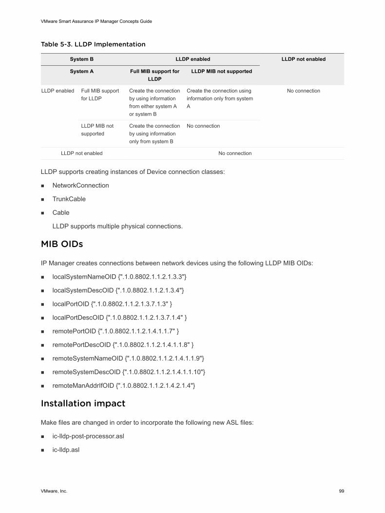
Table 5-3. LLDP Implementation
System B LLDP enabled LLDP not enabled
System A Full MIB support forLLDP
LLDP MIB not supported
LLDP enabled Full MIB supportfor LLDP
Create the connectionby using informationfrom either system Aor system B
Create the connection usinginformation only from systemA
No connection
LLDP MIB notsupported
Create the connectionby using informationonly from system B
No connection
LLDP not enabled No connection
LLDP supports creating instances of Device connection classes:
n NetworkConnection
n TrunkCable
n Cable
LLDP supports multiple physical connections.
MIB OIDs
IP Manager creates connections between network devices using the following LLDP MIB OIDs:
n localSystemNameOID {".1.0.8802.1.1.2.1.3.3"}
n localSystemDescOID {".1.0.8802.1.1.2.1.3.4"}
n localPortOID {".1.0.8802.1.1.2.1.3.7.1.3" }
n localPortDescOID {".1.0.8802.1.1.2.1.3.7.1.4" }
n remotePortOID {".1.0.8802.1.1.2.1.4.1.1.7" }
n remotePortDescOID {".1.0.8802.1.1.2.1.4.1.1.8" }
n remoteSystemNameOID {".1.0.8802.1.1.2.1.4.1.1.9"}
n remoteSystemDescOID {".1.0.8802.1.1.2.1.4.1.1.10"}
n remoteManAddrIfOID {".1.0.8802.1.1.2.1.4.2.1.4"}
Installation impact
Make files are changed in order to incorporate the following new ASL files:
n ic-lldp-post-processor.asl
n ic-lldp.asl
VMware Smart Assurance IP Manager Concepts Guide
VMware, Inc. 99
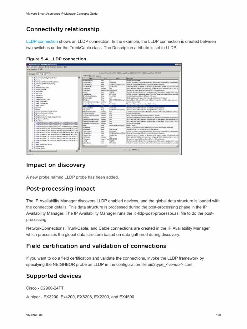
Connectivity relationship
LLDP connection shows an LLDP connection. In the example, the LLDP connection is created betweentwo switches under the TrunkCable class. The Description attribute is set to LLDP.
Figure 5-4. LLDP connection
Impact on discovery
A new probe named LLDP probe has been added.
Post-processing impact
The IP Availability Manager discovers LLDP enabled devices, and the global data structure is loaded withthe connection details. This data structure is processed during the post-processing phase in the IPAvailability Manager. The IP Availability Manager runs the ic-lldp-post-processor.asl file to do the post-processing.
NetworkConnections, TrunkCable, and Cable connections are created in the IP Availability Managerwhich processes the global data structure based on data gathered during discovery.
Field certification and validation of connections
If you want to do a field certification and validate the connections, invoke the LLDP framework byspecifying the NEIGHBOR probe as LLDP in the configuration file oid2type_<vendor>.conf.
Supported devices
Cisco - C2960-24TT
Juniper - EX3200, Ex4200, EX8208, EX2200, and EX4500
VMware Smart Assurance IP Manager Concepts Guide
VMware, Inc. 100
Force10 - E600
Huawei Quidway Switches
Unique VLAN naming
The collection of bridges in a local area network (LAN) can be depicted as a graph whose nodes arebridges and LAN segments (or cables), and whose edges are the interfaces connecting the bridges to thesegments. To break loops in the LAN while maintaining access to all LAN segments, the bridgescollectively compute a spanning tree.
For all switches in a network to agree on a loop-free topology, a common frame of reference must exist touse as a guide. This reference point is called the Root Bridge. An election process among all connectedswitches chooses the Root Bridge. Each switch has a unique Bridge ID.
When a switch first powers up, it assumes that it is the Root Bridge itself. Every switch begins by sendingout Bridge Protocol Data Units (BPDUs) with a Root Bridge ID equal to its own Bridge ID and a SenderBridge ID that is its own Bridge ID. The Sender Bridge ID simply tells other switches who is the actualsender of the BPDU message. After a Root Bridge is decided on, configuration BPDUs are sent only bythe Root Bridge. All other bridges must forward or relay the BPDUs, adding their own Sender Bridge IDsto the message.
In earlier releases, IP Manager created VLANs using VLAN IDs. This resulted in duplication of VLANobjects when multiple domains were configured with the same VLAN ID. VLANs were represented asVLAN-<VLAN ID>, for example, VLAN-1003. So the user could not discover all VLAN objects since thetopology did not have all the VLAN objects because of VLAN ID duplication.
In this release, IP Manager creates unique VLANs from the Root Bridge ID and VLAN ID, that is, VLAN-<Root Bridge ID>-<VLANID>.
Each VLAN has a different Root Bridge ID because the participating members may be different. From theBRIDGE-MIB, dot1dStpDesignatedRoot (Root Bridge ID) is derived. The dot1dStpDesignatedRoot (OID:1.3.6.1.2.1.17.2.5) is a combination of dot1dStpPriority (1.3.6.1.2.1.17.2.2 - Value of the write-able portionof the Bridge ID) and dot1dBaseBridgeAddress (The MAC address used by this bridge when it must bereferred to in a unique fashion. When concatenated with dot1dStpPriority, a unique BridgeIdentifier isformed which is used in the Spanning Tree Protocol). The combined representation of Root Bridge ID andVLANID in this release is: VLAN-<Root Bridge ID>-<VLANID>.
Depending on the device types, there could be other ID added to the VLAN name, for example:
Alcatel-PR driver - Device name is added after "VLAN" class name:
VLAN-196.36.122.235-00-E0-B1-62-C8-3B-1
VLAN-196.36.122.235-00-E0-B1-62-C8-3B-2
Alcatel-Omni driver - The "Alcatel-Omni" driver is added after the VLAN class name:
VLAN-Alcatel-Omni-00-D0-95-4E-A2-81-1
VMware Smart Assurance IP Manager Concepts Guide
VMware, Inc. 101
A new parameter “STPVLANNamingEnabled” is added in the discovery.conf file. STP based VLANunique naming discovery is enabled by incorporating the root bride ID as part of the VLAN name.
Default Value = TRUE
STPVLANNamingEnabled = TRUE
It is set to TRUE (by default) to enable VLAN unique naming by incorporating STP root bridge ID as partof the VLAN name during IP Manager discovery. If it is set to FALSE, the STP root bridge ID will not beincluded in the VLAN name.
Note Here the Root Bridge ID is formed by using only dot1dBaseBridgeAddress (MAC address). Thedot1dStpPriority part from dot1dStpDesignatedRoot is not used.
If the Root Bridge ID changes due to network configuration changes, then the SVLAN name needs to bechanged too. Any change to the SVLAN name will reflect after performing a "Rediscover All".
For Cisco devices supporting CISCO-VTP-MIB, the combined representation of Root Bridge ID andVLANID is: VLAN-<Root Bridge ID>-<VLANID>[VTP name], for example, VLAN-00-19-AA-CE-1B-00-10[VSAN_NEW].
OID Info Tool
The OID Info tool enables you to view the list of OIDs that are used to discover and monitor devices suchas Host, Router, Switch, and so on. The OID information helps identify faults in the configuration of theSNMP agent of the device. The OID Info tool displays the list of OIDs and their SNMP values for a device.It fetches the value of the OIDs from the device and compares the SNMP values against the values in thetopology.
The OID Info tool is introduced in the IP Manager and SAM Console versions from the 9.2 release and isnot available in older versions. The OIDs can be viewed through the command line or through the OIDInfo option in the Domain Manager Administration Console.
The VMware Smart Assurance IP Manager User Guide provides more information on the OID Info tool.
ESX Server Certification
The VMware ESX server has been certified as a host. The interface monitoring of an ESX server is doneusing VMware SNMP agent.
The ESX server certification allows:
n Connection establishment between an ESX host, which could be a standard virtual switch (vSS) or avirtual distributed switch (vDS) and a physical switch. This is done using Cisco Discovery Protocol.
n Impact propagation of the physical switch failure on VMs and ESX.
Attributes for ESX Host
VMware Smart Assurance IP Manager Concepts Guide
VMware, Inc. 102
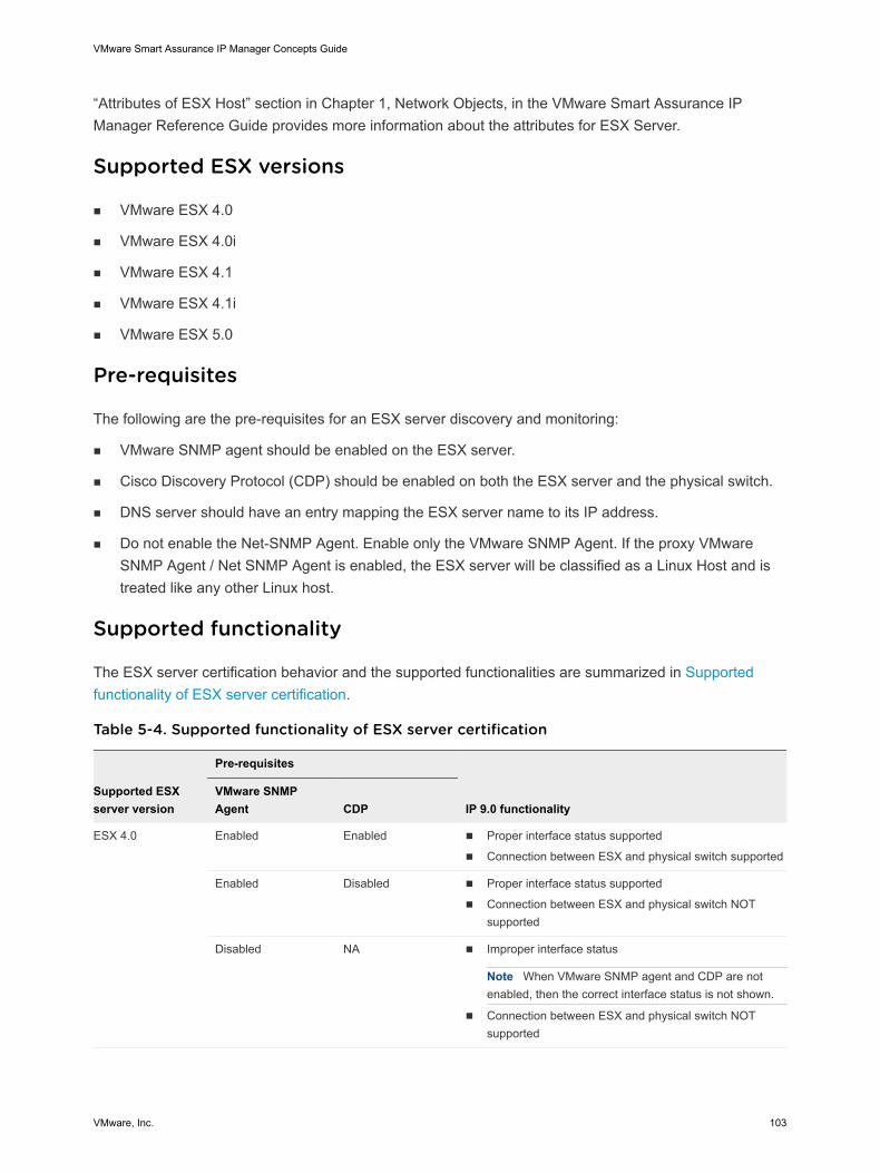
“Attributes of ESX Host” section in Chapter 1, Network Objects, in the VMware Smart Assurance IPManager Reference Guide provides more information about the attributes for ESX Server.
Supported ESX versions
n VMware ESX 4.0
n VMware ESX 4.0i
n VMware ESX 4.1
n VMware ESX 4.1i
n VMware ESX 5.0
Pre-requisites
The following are the pre-requisites for an ESX server discovery and monitoring:
n VMware SNMP agent should be enabled on the ESX server.
n Cisco Discovery Protocol (CDP) should be enabled on both the ESX server and the physical switch.
n DNS server should have an entry mapping the ESX server name to its IP address.
n Do not enable the Net-SNMP Agent. Enable only the VMware SNMP Agent. If the proxy VMwareSNMP Agent / Net SNMP Agent is enabled, the ESX server will be classified as a Linux Host and istreated like any other Linux host.
Supported functionality
The ESX server certification behavior and the supported functionalities are summarized in Supportedfunctionality of ESX server certification.
Table 5-4. Supported functionality of ESX server certification
Supported ESXserver version
Pre-requisites
IP 9.0 functionalityVMware SNMPAgent CDP
ESX 4.0 Enabled Enabled n Proper interface status supported
n Connection between ESX and physical switch supported
Enabled Disabled n Proper interface status supported
n Connection between ESX and physical switch NOTsupported
Disabled NA n Improper interface status
Note When VMware SNMP agent and CDP are notenabled, then the correct interface status is not shown.
n Connection between ESX and physical switch NOTsupported
VMware Smart Assurance IP Manager Concepts Guide
VMware, Inc. 103
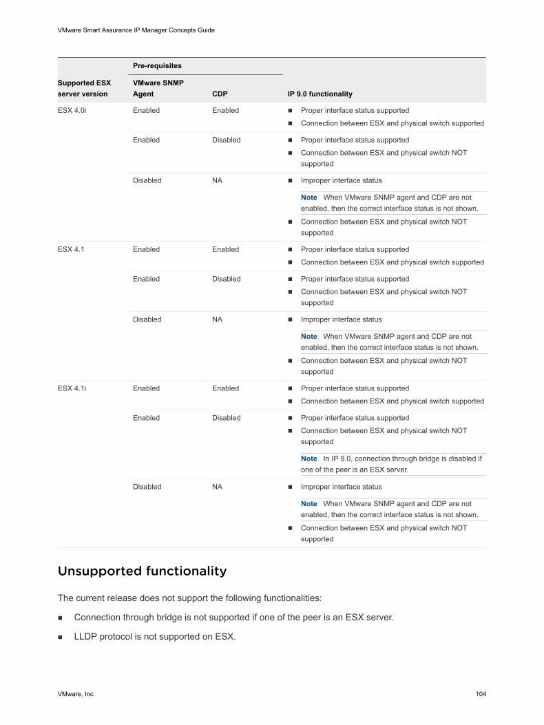
Supported ESXserver version
Pre-requisites
IP 9.0 functionalityVMware SNMPAgent CDP
ESX 4.0i Enabled Enabled n Proper interface status supported
n Connection between ESX and physical switch supported
Enabled Disabled n Proper interface status supported
n Connection between ESX and physical switch NOTsupported
Disabled NA n Improper interface status
Note When VMware SNMP agent and CDP are notenabled, then the correct interface status is not shown.
n Connection between ESX and physical switch NOTsupported
ESX 4.1 Enabled Enabled n Proper interface status supported
n Connection between ESX and physical switch supported
Enabled Disabled n Proper interface status supported
n Connection between ESX and physical switch NOTsupported
Disabled NA n Improper interface status
Note When VMware SNMP agent and CDP are notenabled, then the correct interface status is not shown.
n Connection between ESX and physical switch NOTsupported
ESX 4.1i Enabled Enabled n Proper interface status supported
n Connection between ESX and physical switch supported
Enabled Disabled n Proper interface status supported
n Connection between ESX and physical switch NOTsupported
Note In IP 9.0, connection through bridge is disabled ifone of the peer is an ESX server.
Disabled NA n Improper interface status
Note When VMware SNMP agent and CDP are notenabled, then the correct interface status is not shown.
n Connection between ESX and physical switch NOTsupported
Unsupported functionality
The current release does not support the following functionalities:
n Connection through bridge is not supported if one of the peer is an ESX server.
n LLDP protocol is not supported on ESX.
VMware Smart Assurance IP Manager Concepts Guide
VMware, Inc. 104
n NetSNMP agent features such as Host Resource Monitoring (Memory, Processor and so on) andProcess Monitoring in EISM.
Cisco Nexus 1000V implementation
The Nexus 1000V switch allows the connection between a physical switch and an ESX host by usingCDP (Cisco Discovery Protocol) data. The Nexus 1000V switch is installed on an ESX host.
The main features of the Nexus 1000V implementation in IP:
n It shows the impact of a physical switch failure on the VMs that are connected to the Nexus 1000Vswitch.
n It allows the creation of cable connection between a physical switch and an ESX server, that hoststhe Nexus 1000V switch.
Requirements
The following are the requirements for the Nexus 1000V implementation:
n The physical switch should be a Cisco switch.
n CDP (Cisco Discovery Protocol) should be enabled on the physical switch and Nexus 1000V.
n SNMP should be enabled on Nexus 1000V
n The discovery of the ESX host and the Nexus 1000V switch is required, to allow the discovery of theCDP cable connection.
Note If the ESX host is not discovered, then the CDP cable connection cannot be discovered.
To create connections between a physical switch and an ESX server, Cisco Discovery Protocol (CDP)should be enabled on both the physical switch and the vSwitch (Standard vSwitch, DistributedvSwitch and Nexus 1000 vSwitch) installed on the ESX server. CDP should be running in both Listenand Advertize mode. If CDP is not enabled in both Listen and Advertize mode, then the connectionsbetween the physical switch and the ESX server will not be created.
The ESX hostname should have an entry in DNS server mapping to ESX IP address.
Cisco Nexus 1000v certification
The Cisco Nexus 1000V switch, with system ObjectID .1.3.6.1.4.1.9.12.3.1.3.840, has been recertified asvSwitch. Earlier, it was certified as a switch.
Relationship between Nexus 1000v, VMs and ESX server
VMware Smart Assurance IP Manager Concepts Guide
VMware, Inc. 105
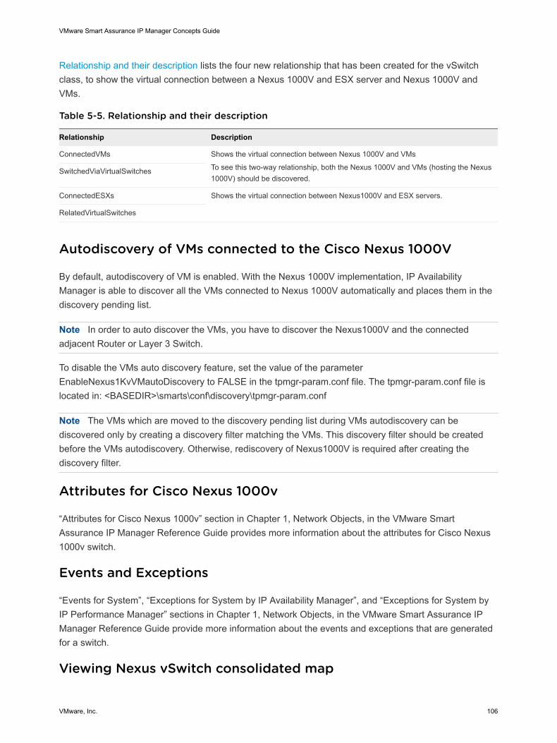
Relationship and their description lists the four new relationship that has been created for the vSwitchclass, to show the virtual connection between a Nexus 1000V and ESX server and Nexus 1000V andVMs.
Table 5-5. Relationship and their description
Relationship Description
ConnectedVMs Shows the virtual connection between Nexus 1000V and VMs
To see this two-way relationship, both the Nexus 1000V and VMs (hosting the Nexus1000V) should be discovered.
SwitchedViaVirtualSwitches
ConnectedESXs Shows the virtual connection between Nexus1000V and ESX servers.
RelatedVirtualSwitches
Autodiscovery of VMs connected to the Cisco Nexus 1000V
By default, autodiscovery of VM is enabled. With the Nexus 1000V implementation, IP AvailabilityManager is able to discover all the VMs connected to Nexus 1000V automatically and places them in thediscovery pending list.
Note In order to auto discover the VMs, you have to discover the Nexus1000V and the connectedadjacent Router or Layer 3 Switch.
To disable the VMs auto discovery feature, set the value of the parameterEnableNexus1KvVMautoDiscovery to FALSE in the tpmgr-param.conf file. The tpmgr-param.conf file islocated in: <BASEDIR>\smarts\conf\discovery\tpmgr-param.conf
Note The VMs which are moved to the discovery pending list during VMs autodiscovery can bediscovered only by creating a discovery filter matching the VMs. This discovery filter should be createdbefore the VMs autodiscovery. Otherwise, rediscovery of Nexus1000V is required after creating thediscovery filter.
Attributes for Cisco Nexus 1000v
“Attributes for Cisco Nexus 1000v” section in Chapter 1, Network Objects, in the VMware SmartAssurance IP Manager Reference Guide provides more information about the attributes for Cisco Nexus1000v switch.
Events and Exceptions
“Events for System”, “Exceptions for System by IP Availability Manager”, and “Exceptions for System byIP Performance Manager” sections in Chapter 1, Network Objects, in the VMware Smart Assurance IPManager Reference Guide provide more information about the events and exceptions that are generatedfor a switch.
Viewing Nexus vSwitch consolidated map
VMware Smart Assurance IP Manager Concepts Guide
VMware, Inc. 106
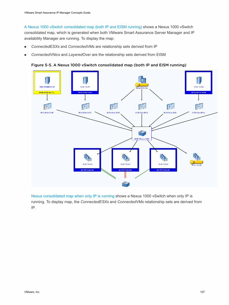
A Nexus 1000 vSwitch consolidated map (both IP and EISM running) shows a Nexus 1000 vSwitchconsolidated map, which is generated when both VMware Smart Assurance Server Manager and IPavailability Manager are running. To display the map:
n ConnectedESXs and ConnectedVMs are relationship sets derived from IP
n ConnectedVNics and LayeredOver are the relationship sets derived from EISM
Figure 5-5. A Nexus 1000 vSwitch consolidated map (both IP and EISM running)
Nexus consolidated map when only IP is running shows a Nexus 1000 vSwitch when only IP isrunning. To display map, the ConnectedESXs and ConnectedVMs relationship sets are derived fromIP.
VMware Smart Assurance IP Manager Concepts Guide
VMware, Inc. 107
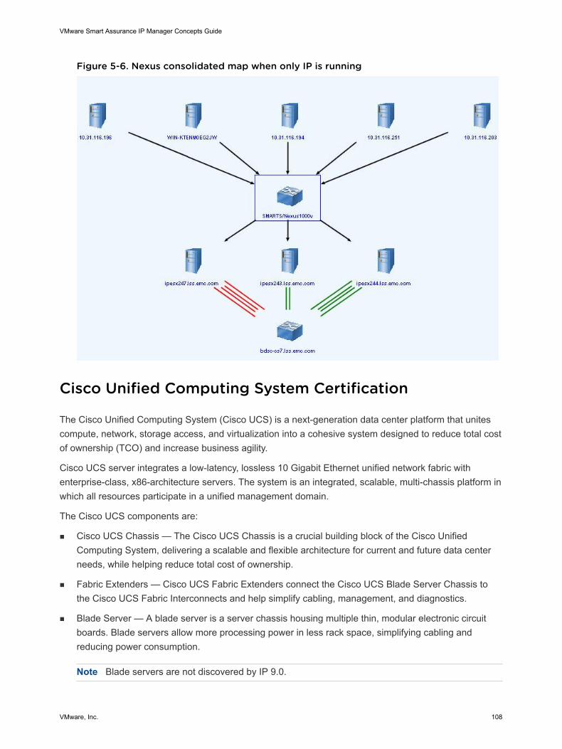
Figure 5-6. Nexus consolidated map when only IP is running
Cisco Unified Computing System Certification
The Cisco Unified Computing System (Cisco UCS) is a next-generation data center platform that unitescompute, network, storage access, and virtualization into a cohesive system designed to reduce total costof ownership (TCO) and increase business agility.
Cisco UCS server integrates a low-latency, lossless 10 Gigabit Ethernet unified network fabric withenterprise-class, x86-architecture servers. The system is an integrated, scalable, multi-chassis platform inwhich all resources participate in a unified management domain.
The Cisco UCS components are:
n Cisco UCS Chassis — The Cisco UCS Chassis is a crucial building block of the Cisco UnifiedComputing System, delivering a scalable and flexible architecture for current and future data centerneeds, while helping reduce total cost of ownership.
n Fabric Extenders — Cisco UCS Fabric Extenders connect the Cisco UCS Blade Server Chassis tothe Cisco UCS Fabric Interconnects and help simplify cabling, management, and diagnostics.
n Blade Server — A blade server is a server chassis housing multiple thin, modular electronic circuitboards. Blade servers allow more processing power in less rack space, simplifying cabling andreducing power consumption.
Note Blade servers are not discovered by IP 9.0.
VMware Smart Assurance IP Manager Concepts Guide
VMware, Inc. 108
n Fabric Interconnect — Fabric Interconnect is a core part of the Cisco UCS that provides both networkconnectivity and management capabilities to all attached blades and chassis.
The Cisco UCS server portfolio consists of:
n Blade Server platform
n B-Series and the C-Series Rack Mount platform
Note IP 9.0 supports UCS Manager version 1.4 only.
The object ID is used to certify the device as Switch or ComputeFabric based on the Cisco NexusOperating System version.
If the IOS version is 1.4, all Cisco USC related components are discovered.
If the IOS version is 1.3 or below, then only Switch discovery happens.
The components to support Cisco UCS certification are:
n ComputeFabric — Represents the Cisco UCS equipment. It is a platform which converges Compute,Network, Storage Access and Virutalization into an enclosed system to provide a highly flexibleinfrastructure in order to optimize application environments. It is composed of:
n Cisco UCS Chassis (represented as BladeEnclosureManager)
n Fabric Interconnect (represented as Switch)
n BladeEnclosureManager — Represents all the Cisco UCS chassis components. It is aUnitaryComputerSystem that packages the following physical components:
n Cards (Fabric Extenders)
n PowerSupply
n Fan
n TemperatureSensor
n VoltageSensor
n Fabric Extenders — Fabric Extenders are elements that can be plugged into the Cisco UCS Chassis.The Fabric Extender is represented as Card in the IP topology. The card has a PartOf/ComposedOfrelationship with BladeEnclosureManager.
n Fabric Interconnect — The Fabric Interconnect is represented as Switch in the IP topology. When twoFabric Interconnect switches of an UCS are discovered, trunk cable connections are created betweenthe Fabric Interconnect port and BladeEnclosureManager port.
n For Fabric Interconnect port connected to the BladeEnclosureManager, IP Availability Managersets the PortType as ACCESS.
Note IP Availability Manager sets this port as an ACCESS port because the peer port does notbelong to the switch, but belongs to the BladeEnclosureManager.
VMware Smart Assurance IP Manager Concepts Guide
VMware, Inc. 109
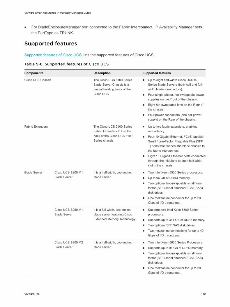
n For BladeEnclosureManager port connected to the Fabric Interconnect, IP Availability Manager setsthe PortType as TRUNK.
Supported features
Supported features of Cisco UCS lists the supported features of Cisco UCS.
Table 5-6. Supported features of Cisco UCS
Components Description Supported features
Cisco UCS Chassis The Cisco UCS 5100 SeriesBlade Server Chassis is acrucial building block of theCisco UCS.
n Up to eight half-width Cisco UCS B-Series Blade Servers (both half and full-width blade form factors).
n Four single-phase, hot-swappable powersupplies on the Front of the chassis.
n Eight hot-swappable fans on the Rear ofthe chassis.
n Four power connectors (one per powersupply) on the Rear of the chassis.
Fabric Extenders The Cisco UCS 2100 SeriesFabric Extenders fit into theback of the Cisco UCS 5100Series chassis.
n Up to two fabric extenders, enablingredundancy.
n Four 10 Gigabit Ethernet, FCoE-capable,Small Form-Factor Pluggable Plus (SFP+) ports that connect the blade chassis tothe fabric interconnect.
n Eight 10 Gigabit Ethernet ports connectedthrough the midplane to each half-widthslot in the chassis.
Blade Server Cisco UCS B200 M1Blade Server
It is a half-width, two-socketblade server.
n Two Intel Xeon 5500 Series processors.
n Up to 96 GB of DDR3 memory.
n Two optional hot-swappable small formfactor (SFF) serial attached SCSI (SAS)disk drives.
n One mezzanine connector for up to 20Gbps of I/O throughput.
Cisco UCS B250 M1Blade Server
It is a full-width, two-socketblade server featuring CiscoExtended Memory Technology.
n Supports two Intel Xeon 5500 Seriesprocessors.
n Supports up to 384 GB of DDR3 memory.
n Two optional SFF SAS disk drives.
n Two mezzanine connections for up to 40Gbps of I/O throughput.
Cisco UCS B200 M2Blade Server
It is a half-width, two-socketblade server.
n Two Intel Xeon 5600 Series Processors
n Supports up to 96 GB of DDR3 memory
n Two optional hot-swappable small formfactor (SFF) serial attached SCSI (SAS)disk drives
n One mezzanine connector for up to 20Gbps of I/O throughput.
VMware Smart Assurance IP Manager Concepts Guide
VMware, Inc. 110
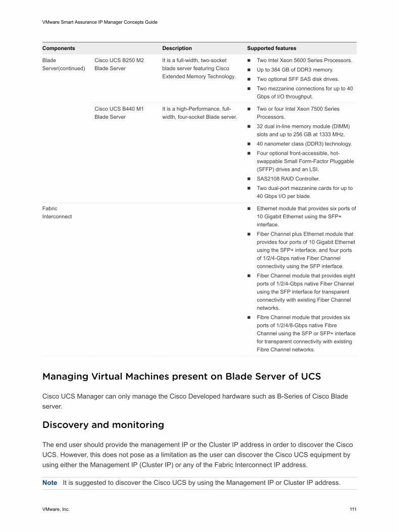
Components Description Supported features
BladeServer(continued)
Cisco UCS B250 M2Blade Server
It is a full-width, two-socketblade server featuring CiscoExtended Memory Technology.
n Two Intel Xeon 5600 Series Processors.
n Up to 384 GB of DDR3 memory.
n Two optional SFF SAS disk drives.
n Two mezzanine connections for up to 40Gbps of I/O throughput.
Cisco UCS B440 M1Blade Server
It is a high-Performance, full-width, four-socket Blade server.
n Two or four Intel Xeon 7500 SeriesProcessors.
n 32 dual in-line memory module (DIMM)slots and up to 256 GB at 1333 MHz.
n 40 nanometer class (DDR3) technology.
n Four optional front-accessible, hot-swappable Small Form-Factor Pluggable(SFFP) drives and an LSI.
n SAS2108 RAID Controller.
n Two dual-port mezzanine cards for up to40 Gbps I/O per blade.
FabricInterconnect
n Ethernet module that provides six ports of10 Gigabit Ethernet using the SFP+interface.
n Fiber Channel plus Ethernet module thatprovides four ports of 10 Gigabit Ethernetusing the SFP+ interface, and four portsof 1/2/4-Gbps native Fiber Channelconnectivity using the SFP interface.
n Fiber Channel module that provides eightports of 1/2/4-Gbps native Fiber Channelusing the SFP interface for transparentconnectivity with existing Fiber Channelnetworks.
n Fibre Channel module that provides sixports of 1/2/4/8-Gbps native FibreChannel using the SFP or SFP+ interfacefor transparent connectivity with existingFibre Channel networks.
Managing Virtual Machines present on Blade Server of UCS
Cisco UCS Manager can only manage the Cisco Developed hardware such as B-Series of Cisco Bladeserver.
Discovery and monitoring
The end user should provide the management IP or the Cluster IP address in order to discover the CiscoUCS. However, this does not pose as a limitation as the user can discover the Cisco UCS equipment byusing either the Management IP (Cluster IP) or any of the Fabric Interconnect IP address.
Note It is suggested to discover the Cisco UCS by using the Management IP or Cluster IP address.
VMware Smart Assurance IP Manager Concepts Guide
VMware, Inc. 111
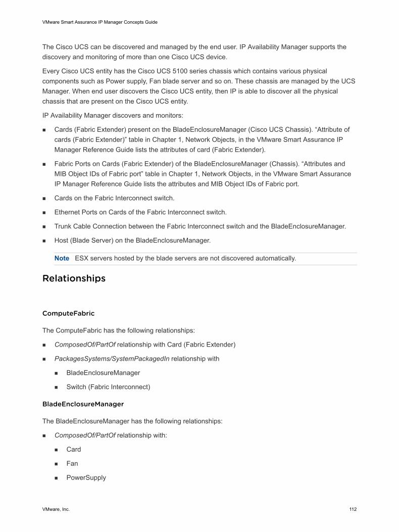
The Cisco UCS can be discovered and managed by the end user. IP Availability Manager supports thediscovery and monitoring of more than one Cisco UCS device.
Every Cisco UCS entity has the Cisco UCS 5100 series chassis which contains various physicalcomponents such as Power supply, Fan blade server and so on. These chassis are managed by the UCSManager. When end user discovers the Cisco UCS entity, then IP is able to discover all the physicalchassis that are present on the Cisco UCS entity.
IP Availability Manager discovers and monitors:
n Cards (Fabric Extender) present on the BladeEnclosureManager (Cisco UCS Chassis). “Attribute ofcards (Fabric Extender)” table in Chapter 1, Network Objects, in the VMware Smart Assurance IPManager Reference Guide lists the attributes of card (Fabric Extender).
n Fabric Ports on Cards (Fabric Extender) of the BladeEnclosureManager (Chassis). “Attributes andMIB Object IDs of Fabric port” table in Chapter 1, Network Objects, in the VMware Smart AssuranceIP Manager Reference Guide lists the attributes and MIB Object IDs of Fabric port.
n Cards on the Fabric Interconnect switch.
n Ethernet Ports on Cards of the Fabric Interconnect switch.
n Trunk Cable Connection between the Fabric Interconnect switch and the BladeEnclosureManager.
n Host (Blade Server) on the BladeEnclosureManager.
Note ESX servers hosted by the blade servers are not discovered automatically.
Relationships
ComputeFabric
The ComputeFabric has the following relationships:
n ComposedOf/PartOf relationship with Card (Fabric Extender)
n PackagesSystems/SystemPackagedIn relationship with
n BladeEnclosureManager
n Switch (Fabric Interconnect)
BladeEnclosureManager
The BladeEnclosureManager has the following relationships:
n ComposedOf/PartOf relationship with:
n Card
n Fan
n PowerSupply
VMware Smart Assurance IP Manager Concepts Guide
VMware, Inc. 112
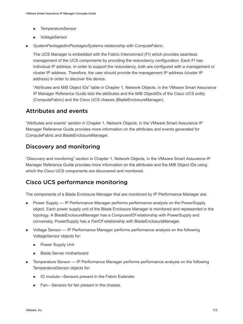
n TemperatureSensor
n VoltageSensor
n SystemPackagedIn/PackagesSystems relationship with ComputeFabric.
The UCS Manager is embedded with the Fabric Interconnect (FI) which provides seamlessmanagement of the UCS components by providing the redundancy configuration. Each FI hasindividual IP address. In order to support the redundancy, both are configured with a management orcluster IP address. Therefore, the user should provide the management IP address (cluster IPaddress) in order to discover the device.
“Attributes and MIB Object IDs” table in Chapter 1, Network Objects, in the VMware Smart AssuranceIP Manager Reference Guide lists the attributes and the MIB ObjectIDs of the Cisco UCS entity(ComputeFabric) and the Cisco UCS chassis (BladeEnclosureManager).
Attributes and events
“Attributes and events” section in Chapter 1, Network Objects, in the VMware Smart Assurance IPManager Reference Guide provides more information on the attributes and events generated forComputeFabric and BladeEnclosureManager.
Discovery and monitoring
“Discovery and monitoring” section in Chapter 1, Network Objects, in the VMware Smart Assurance IPManager Reference Guide provides more information on the attributes and the MIB Object IDs usingwhich the Cisco UCS components are discovered and monitored.
Cisco UCS performance monitoring
The components of a Blade Enclosure Manager that are monitored by IP Performance Manager are:
n Power Supply — IP Performance Manager performs performance analysis on the PowerSupplyobject. Each power supply unit of the Blade Enclosure Manager is monitored and represented in thetopology. A BladeEnclosureManager has a ComposedOf relationship with PowerSupply andconversely, PowerSupply has a PartOf relationship with BladeEnclosureManager.
n Voltage Sensor — IP Performance Manager performs performance analysis on the followingVoltageSensor objects for:
n Power Supply Unit
n Blade Server motherboard
n Temperature Sensor — IP Performance Manager performs performance analysis on the followingTemperatureSensor objects for:
n IO module—Sensors present in the Fabric Extender.
n Fan—Sensors for fan present in the chassis.
VMware Smart Assurance IP Manager Concepts Guide
VMware, Inc. 113
n Motherboard Temperature counters for:
• Motherboard Front Temperature
• Motherboard Rear Temperature
• Motherboard Rear Temperature Left
• Motherboard Rear Temperature Right
n Power supply in the chassis
n Fan—IP Performance Manager performs performance analysis of the Fan. Each Fan unit of theBladeEnclosureManager is monitored and represented in the topology. The relationships of aBladeEnclosureManager with fan are:
n ComposedOf relationship with Fan
n Conversely, PartOf relationship with BladeEnclosureManager
All the thresholds settings are configured in the Polling and Thresholds console.
Faults and Exceptions
“Faults and Exceptions” section in Chapter 1, Network Objects, in the VMware Smart Assurance IPManager Reference Guide provides more information on the Faults and Exceptions of Blade EnclosureManager.
Fabric Interconnect performance monitoring
IP Performance Manager discovers and monitors the following components of a Fabric Interconnectswitch:
n Temperature sensors
n Voltage sensors
n Power supply
n Fan
n Memory
The user can discover the components present in the Fabric Interconnect switch using the MIBObject IDs that are listed in the respective tables in the following sections:
n Discovery and monitoring of temperature sensors
n Discovery and monitoring of Voltage sensor
n Discovery and monitoring of Power supply
n Discovery and monitoring of Fan
VMware Smart Assurance IP Manager Concepts Guide
VMware, Inc. 114
n Discovery and monitoring of Memory
Note The discovery and monitoring of the Fabric Interconnect CPU is not supported as there is noinformation about it in the Cisco UCS MIB.
Discovery and monitoring of temperature sensors
The temperature sensors present in a Fabric Interconnect are used to discover and monitor a FabricInterconnect. The various temperature sensors are:
n Fabric Interconnect’s Fan Inlet1
n Fabric Interconnect’s Fan Inlet2
n Fabric Interconnect’s Fan Inlet 3
n Fabric Interconnect’s Fan Inlet 4
n Fabric Interconnect’s Motherboard Outlet 1
n Fabric Interconnect’s Motherboard Outlet 2
n Fabric Interconnect’s Power Supply Inlet 1
n Fabric Interconnect’s Power Supply Inlet 2
“MIB Object ID of temperature sensor used for discovery” table in Chapter 1, Network Objects, in theVMware Smart Assurance IP Manager Reference Guide lists the MIB Object IDs used for discoveryof temperature sensor in a Fabric Interconnect.
Discovery and monitoring of Voltage sensor
“MIB Object IDs used for discovery and monitoring of voltage sensor” table in Chapter 1, NetworkObjects, in the VMware Smart Assurance IP Manager Reference Guide lists the MIB Object IDs used fordiscovery and monitoring of voltage sensor in a Fabric Interconnect.
Discovery and monitoring of Power supply
“MIB Object IDs used for discovery and monitoring of Power Supply in Fabric Interconnect” table inChapter 1, Network Objects, in the VMware Smart Assurance IP Manager Reference Guide lists the MIBObject IDs used for discovery and monitoring of power supply present in a Fabric Interconnect.
Discovery and monitoring of Fan
“MIB Object IDs used for discovery of fan in Fabric Interconnect” table in Chapter 1, Network Objects, inthe VMware Smart Assurance IP Manager Reference Guide lists the MIB Object IDs used for discoveryand monitoring of fan instances in a Fabric Interconnect.
Discovery and monitoring of Memory
VMware Smart Assurance IP Manager Concepts Guide
VMware, Inc. 115
“MIB Object IDs for discovery and monitoring of memory instances in Fabric Interconnect” table inChapter 1, Network Objects, in the VMware Smart Assurance IP Manager Reference Guide lists the MIBObject IDs used for discovery and monitoring of memory instance in a Fabric Interconnect.
UCS Map
You can view the details about ComputeFabric, BladeEnclosureManager and all related connections inthe following format:
n Global Manager Administration Console
n Notification Log
n Topology Browser
n Containment view
n Maps
Viewing maps
The physical representation of a ComputeFabric is represented by the option Show Map. The map showsrelationships among topology elements, indicating the status of each element. In a map display, a node isa graphical representation of an element, and an edge is a graphical representation of a relationship orconnection between elements.
Viewing the ComputeFabric connectivity map
VMware Smart Assurance IP Manager Concepts Guide
VMware, Inc. 116
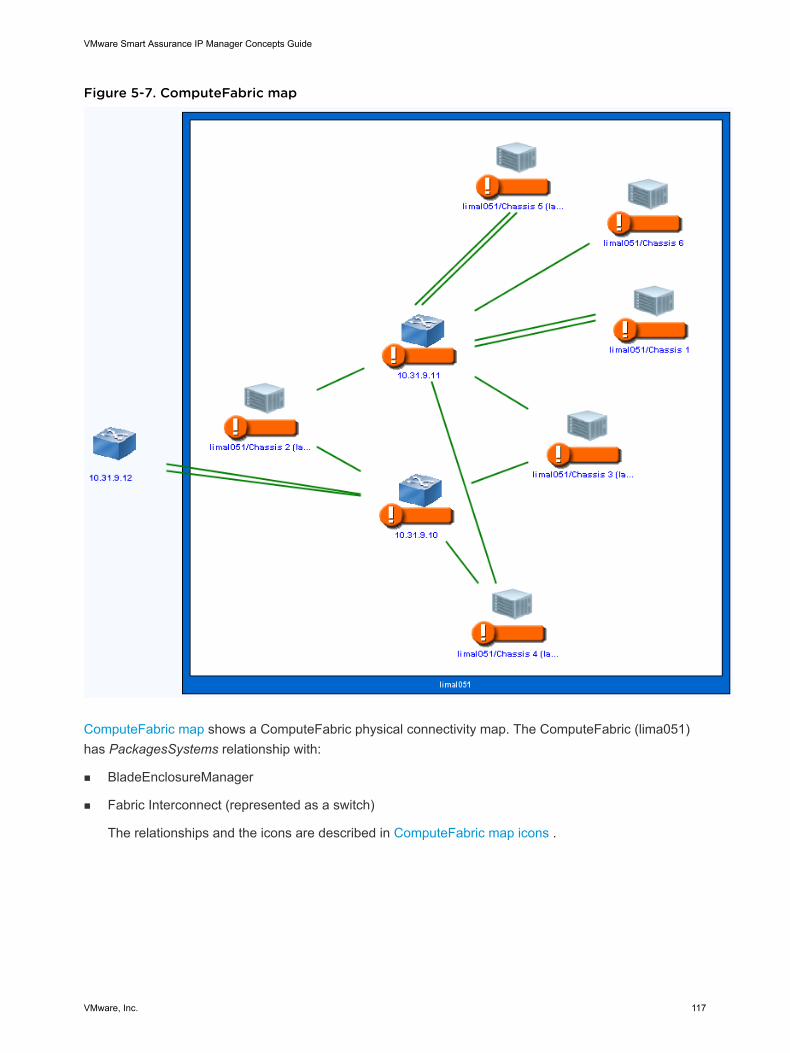
Figure 5-7. ComputeFabric map
ComputeFabric map shows a ComputeFabric physical connectivity map. The ComputeFabric (lima051)has PackagesSystems relationship with:
n BladeEnclosureManager
n Fabric Interconnect (represented as a switch)
The relationships and the icons are described in ComputeFabric map icons .
VMware Smart Assurance IP Manager Concepts Guide
VMware, Inc. 117
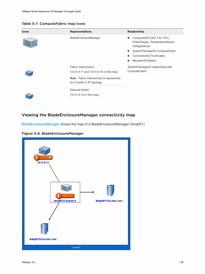
Table 5-7. ComputeFabric map icons
Icons Representations Relationship
BladeEnclosureManager n ComposedOf Card, Fan, Port,PowerSupply, TemperatureSensor,VoltageSensor
n SystemPackagedIn ComputeFabric
n ConnectedVia TrunkCable
n MemberOf Partition
Fabric Interconnect
(10.31.9.11 and 10.31.9.10 in this map)
Note Fabric Interconnect is representedas a Switch in IP topology.
SystemPackagedIn relationship withComputeFabric.
External Switch
(10.31.9.12 in this map)
Viewing the BladeEnclosureManager connectivity map
BladeEnclosureManager shows the map of a BladeEnclosureManager (lima051)
Figure 5-8. BladeEnclosureManager
VMware Smart Assurance IP Manager Concepts Guide
VMware, Inc. 118
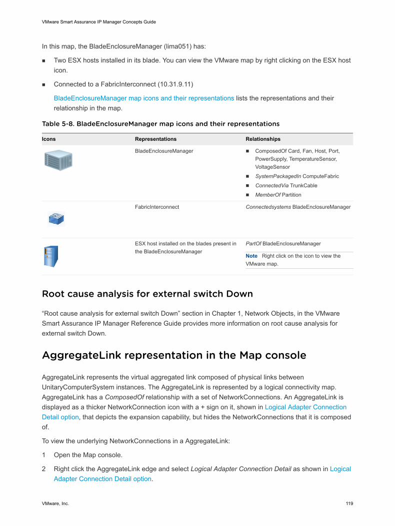
In this map, the BladeEnclosureManager (lima051) has:
n Two ESX hosts installed in its blade. You can view the VMware map by right clicking on the ESX hosticon.
n Connected to a FabricInterconnect (10.31.9.11)
BladeEnclosureManager map icons and their representations lists the representations and theirrelationship in the map.
Table 5-8. BladeEnclosureManager map icons and their representations
Icons Representations Relationships
BladeEnclosureManager n ComposedOf Card, Fan, Host, Port,PowerSupply, TemperatureSensor,VoltageSensor
n SystemPackagedIn ComputeFabric
n ConnectedVia TrunkCable
n MemberOf Partition
FabricInterconnect Connectedsystems BladeEnclosureManager
ESX host installed on the blades present inthe BladeEnclosureManager
PartOf BladeEnclosureManager
Note Right click on the icon to view theVMware map.
Root cause analysis for external switch Down
“Root cause analysis for external switch Down” section in Chapter 1, Network Objects, in the VMwareSmart Assurance IP Manager Reference Guide provides more information on root cause analysis forexternal switch Down.
AggregateLink representation in the Map console
AggregateLink represents the virtual aggregated link composed of physical links betweenUnitaryComputerSystem instances. The AggregateLink is represented by a logical connectivity map.AggregateLink has a ComposedOf relationship with a set of NetworkConnections. An AggregateLink isdisplayed as a thicker NetworkConnection icon with a + sign on it, shown in Logical Adapter ConnectionDetail option, that depicts the expansion capability, but hides the NetworkConnections that it is composedof.
To view the underlying NetworkConnections in a AggregateLink:
1 Open the Map console.
2 Right click the AggregateLink edge and select Logical Adapter Connection Detail as shown in LogicalAdapter Connection Detail option.
VMware Smart Assurance IP Manager Concepts Guide
VMware, Inc. 119
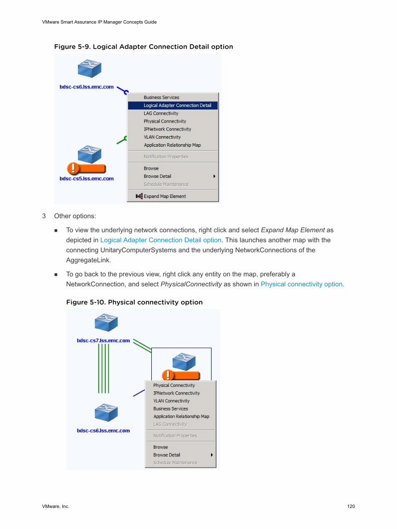
Figure 5-9. Logical Adapter Connection Detail option
3 Other options:
n To view the underlying network connections, right click and select Expand Map Element asdepicted in Logical Adapter Connection Detail option. This launches another map with theconnecting UnitaryComputerSystems and the underlying NetworkConnections of theAggregateLink.
n To go back to the previous view, right click any entity on the map, preferably aNetworkConnection, and select PhysicalConnectivity as shown in Physical connectivity option.
Figure 5-10. Physical connectivity option
VMware Smart Assurance IP Manager Concepts Guide
VMware, Inc. 120
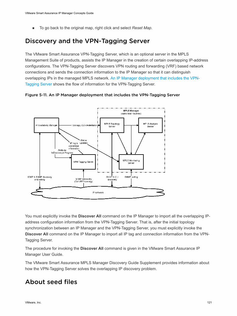
n To go back to the original map, right click and select Reset Map.
Discovery and the VPN-Tagging Server
The VMware Smart Assurance VPN-Tagging Server, which is an optional server in the MPLSManagement Suite of products, assists the IP Manager in the creation of certain overlapping IP-addressconfigurations. The VPN-Tagging Server discovers VPN routing and forwarding (VRF) based networkconnections and sends the connection information to the IP Manager so that it can distinguishoverlapping IPs in the managed MPLS network. An IP Manager deployment that includes the VPN-Tagging Server shows the flow of information for the VPN-Tagging Server.
Figure 5-11. An IP Manager deployment that includes the VPN-Tagging Server
You must explicitly invoke the Discover All command on the IP Manager to import all the overlapping IP-address configuration information from the VPN-Tagging Server. That is, after the initial topologysynchronization between an IP Manager and the VPN-Tagging Server, you must explicitly invoke theDiscover All command on the IP Manager to import all IP tag and connection information from the VPN-Tagging Server.
The procedure for invoking the Discover All command is given in the VMware Smart Assurance IPManager User Guide.
The VMware Smart Assurance MPLS Manager Discovery Guide Supplement provides information abouthow the VPN-Tagging Server solves the overlapping IP discovery problem.
About seed files
VMware Smart Assurance IP Manager Concepts Guide
VMware, Inc. 121
Preparing a seed file is one of two ways to manually add systems to the IP Manager topology. The otherway is by using the Add Agent command, which is described in Using the Add Agent command to initiatediscovery. When autodiscovery is enabled, importing a seed file or adding a candidate system by usingthe Add Agent command initiates the autodiscovery process.
In a seed file, you specify top-level network systems such as switches, routers, hubs, bridges, and hoststhat are to be discovered and monitored by the IP Manager. Then, when you import the seed file, the IPManager discovers the internal structure of these systems.
For example, in the case of a router, you provide the hostname or IP address of one interface, and the IPManager discovers the rest of the interfaces. In the case of a switch, you provide the hostname or IPaddress of the switch’s SNMP agent, and the IP Manager determines the switch’s configuration and howthe switch connects to other systems that are listed in the topology.
Seed files can be used to discover SNMPv1, v2c, or v3 systems in IPv4 or IPv6 networks.
“Seed file related tasks” section in Chapter 3, Discovery, in the VMware Smart Assurance IP ManagerUser Guide, provides more information about tasks related to seed files.
Seed file template
The seed file must be stored on the host on which the IP Manager runs. By default, the IP Managerexpects to find the seed file in the BASEDIR/smarts/local/conf directory. A template seed file namedseedfile is provided in the BASEDIR/smarts/conf directory.
Seed file dual use
The seed entries in the seed file are read by the IP Manager’s topology manager and trap manager atstartup. The topology manager uses the entries and their credentials to contact the seed systems duringdiscovery. The trap manager uses the entries and their credentials to verify and decrypt SNMPv3 trapmessages that are received from SNMPv3-capable seed systems once they are discovered.
Seed file format
A seed file consists of one or more seed entries, each of which represents a discovery candidate system.Each seed entry begins with the hostname or IP address for the candidate system, followed by options forthe system.
Seed-entry system identifiers
For a seed entry that begins with a hostname, you can specify the hostname with or without an explicit IPversion suffix (:v6v4, :v4v6, :v6, or :v4). Here is an example hostname that includes a v4 suffix: Core-ROUTER-1:v4.
If you do not include an explicit IP version suffix, the SM_IP_VERSIONS environment variable controlshow the local name resolution service resolves the hostname to a corresponding IP address. By default,SM_IP_VERSIONS is set to v6v4.
VMware Smart Assurance IP Manager Concepts Guide
VMware, Inc. 122
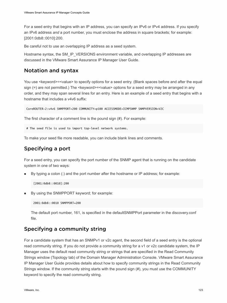
For a seed entry that begins with an IP address, you can specify an IPv6 or IPv4 address. If you specifyan IPv6 address and a port number, you must enclose the address in square brackets; for example:[2001:0db8::0010]:200.
Be careful not to use an overlapping IP address as a seed system.
Hostname syntax, the SM_IP_VERSIONS environment variable, and overlapping IP addresses arediscussed in the VMware Smart Assurance IP Manager User Guide.
Notation and syntax
You use <keyword>=<value> to specify options for a seed entry. (Blank spaces before and after the equalsign (=) are not permitted.) The <keyword>=<value> options for a seed entry may be arranged in anyorder, and they may span several lines for an entry. Here is an example of a seed entry that begins with ahostname that includes a v4v6 suffix:
CoreROUTER-2:v4v6 SNMPPORT=200 COMMUNITY=p100 ACCESSMODE=ICMPSNMP SNMPVERSION=V2C
The first character of a comment line is the pound sign (#). For example:
# The seed file is used to import top-level network systems.
To make your seed file more readable, you can include blank lines and comments.
Specifying a port
For a seed entry, you can specify the port number of the SNMP agent that is running on the candidatesystem in one of two ways:
n By typing a colon (:) and the port number after the hostname or IP address; for example:
[2001:0db8::0010]:200
n By using the SNMPPORT keyword; for example:
2001:0db8::0010 SNMPPORT=200
The default port number, 161, is specified in the defaultSNMPPort parameter in the discovery.conffile.
Specifying a community string
For a candidate system that has an SNMPv1 or v2c agent, the second field of a seed entry is the optionalread community string. If you do not provide a community string for a v1 or v2c candidate system, the IPManager uses the default read community string or strings that are specified in the Read CommunityStrings window (Topology tab) of the Domain Manager Administration Console. VMware Smart AssuranceIP Manager User Guide provides details about how to specify community strings in the Read CommunityStrings window. If the community string starts with the pound sign (#), you must use the COMMUNITYkeyword to specify the read community string.
VMware Smart Assurance IP Manager Concepts Guide
VMware, Inc. 123
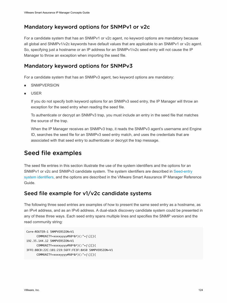
Mandatory keyword options for SNMPv1 or v2c
For a candidate system that has an SNMPv1 or v2c agent, no keyword options are mandatory becauseall global and SNMPv1/v2c keywords have default values that are applicable to an SNMPv1 or v2c agent.So, specifying just a hostname or an IP address for an SNMPv1/v2c seed entry will not cause the IPManager to throw an exception when importing the seed file.
Mandatory keyword options for SNMPv3
For a candidate system that has an SNMPv3 agent, two keyword options are mandatory:
n SNMPVERSION
n USER
If you do not specify both keyword options for an SNMPv3 seed entry, the IP Manager will throw anexception for the seed entry when reading the seed file.
To authenticate or decrypt an SNMPv3 trap, you must include an entry in the seed file that matchesthe source of the trap.
When the IP Manager receives an SNMPv3 trap, it reads the SNMPv3 agent’s username and EngineID, searches the seed file for an SNMPv3 seed entry match, and uses the credentials that areassociated with that seed entry to authenticate or decrypt the trap message.
Seed file examples
The seed file entries in this section illustrate the use of the system identifiers and the options for anSNMPv1 or v2c and SNMPv3 candidate system. The system identifiers are described in Seed-entrysystem identifiers, and the options are described in the VMware Smart Assurance IP Manager ReferenceGuide.
Seed file example for v1/v2c candidate systems
The following three seed entries are examples of how to present the same seed entry as a hostname, asan IPv4 address, and as an IPv6 address. A dual-stack discovery candidate system could be presented inany of these three ways. Each seed entry spans multiple lines and specifies the SNMP version and theread community string:
Core-ROUTER-1 SNMPVERSION=V1
COMMUNITY=xxxxyyyy#%@*&^)(:"=|\][}{
192.35.144.12 SNMPVERSION=V1
COMMUNITY=xxxxyyyy#%@*&^)(:"=|\][}{
3FFE:80C0:22C:101:219:56FF:FE3F:8A50 SNMPVERSION=V1
COMMUNITY=xxxxyyyy#%@*&^)(:"=|\][}{
VMware Smart Assurance IP Manager Concepts Guide
VMware, Inc. 124
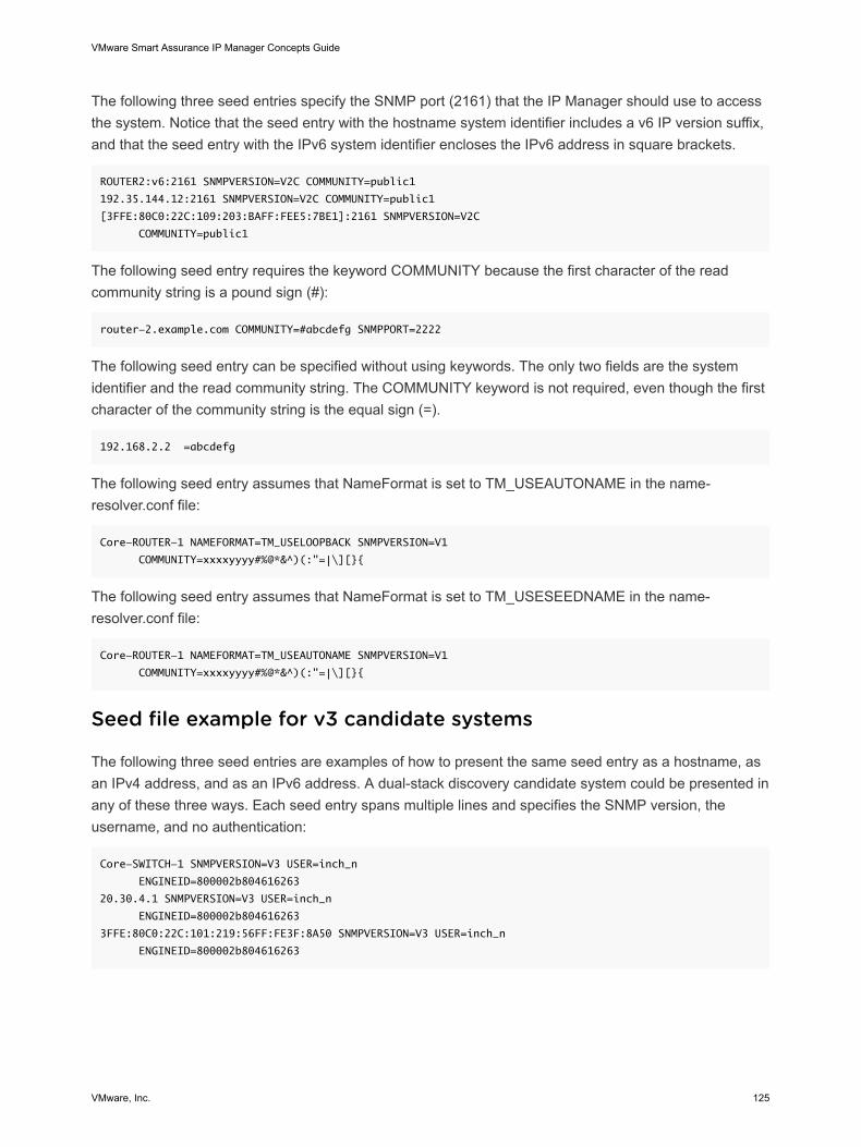
The following three seed entries specify the SNMP port (2161) that the IP Manager should use to accessthe system. Notice that the seed entry with the hostname system identifier includes a v6 IP version suffix,and that the seed entry with the IPv6 system identifier encloses the IPv6 address in square brackets.
ROUTER2:v6:2161 SNMPVERSION=V2C COMMUNITY=public1
192.35.144.12:2161 SNMPVERSION=V2C COMMUNITY=public1
[3FFE:80C0:22C:109:203:BAFF:FEE5:7BE1]:2161 SNMPVERSION=V2C
COMMUNITY=public1
The following seed entry requires the keyword COMMUNITY because the first character of the readcommunity string is a pound sign (#):
router-2.example.com COMMUNITY=#abcdefg SNMPPORT=2222
The following seed entry can be specified without using keywords. The only two fields are the systemidentifier and the read community string. The COMMUNITY keyword is not required, even though the firstcharacter of the community string is the equal sign (=).
192.168.2.2 =abcdefg
The following seed entry assumes that NameFormat is set to TM_USEAUTONAME in the name-resolver.conf file:
Core-ROUTER-1 NAMEFORMAT=TM_USELOOPBACK SNMPVERSION=V1
COMMUNITY=xxxxyyyy#%@*&^)(:"=|\][}{
The following seed entry assumes that NameFormat is set to TM_USESEEDNAME in the name-resolver.conf file:
Core-ROUTER-1 NAMEFORMAT=TM_USEAUTONAME SNMPVERSION=V1
COMMUNITY=xxxxyyyy#%@*&^)(:"=|\][}{
Seed file example for v3 candidate systems
The following three seed entries are examples of how to present the same seed entry as a hostname, asan IPv4 address, and as an IPv6 address. A dual-stack discovery candidate system could be presented inany of these three ways. Each seed entry spans multiple lines and specifies the SNMP version, theusername, and no authentication:
Core-SWITCH-1 SNMPVERSION=V3 USER=inch_n
ENGINEID=800002b804616263
20.30.4.1 SNMPVERSION=V3 USER=inch_n
ENGINEID=800002b804616263
3FFE:80C0:22C:101:219:56FF:FE3F:8A50 SNMPVERSION=V3 USER=inch_n
ENGINEID=800002b804616263
VMware Smart Assurance IP Manager Concepts Guide
VMware, Inc. 125
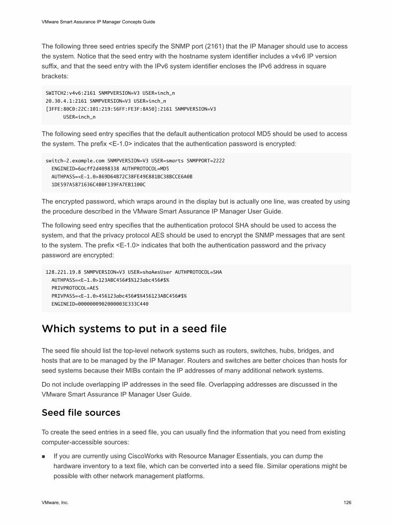
The following three seed entries specify the SNMP port (2161) that the IP Manager should use to accessthe system. Notice that the seed entry with the hostname system identifier includes a v4v6 IP versionsuffix, and that the seed entry with the IPv6 system identifier encloses the IPv6 address in squarebrackets:
SWITCH2:v4v6:2161 SNMPVERSION=V3 USER=inch_n
20.30.4.1:2161 SNMPVERSION=V3 USER=inch_n
[3FFE:80C0:22C:101:219:56FF:FE3F:8A50]:2161 SNMPVERSION=V3
USER=inch_n
The following seed entry specifies that the default authentication protocol MD5 should be used to accessthe system. The prefix <E-1.0> indicates that the authentication password is encrypted:
switch-2.example.com SNMPVERSION=V3 USER=smarts SNMPPORT=2222
ENGINEID=6acff2d4098338 AUTHPROTOCOL=MD5
AUTHPASS=<E-1.0>869D64B72C38FE49E881BC38BCCE6A0B
1DE597A5871636C4B0F139FA7EB1100C
The encrypted password, which wraps around in the display but is actually one line, was created by usingthe procedure described in the VMware Smart Assurance IP Manager User Guide.
The following seed entry specifies that the authentication protocol SHA should be used to access thesystem, and that the privacy protocol AES should be used to encrypt the SNMP messages that are sentto the system. The prefix <E-1.0> indicates that both the authentication password and the privacypassword are encrypted:
128.221.19.8 SNMPVERSION=V3 USER=shaAesUser AUTHPROTOCOL=SHA
AUTHPASS=<E-1.0>123ABC456#$%123abc456#$%
PRIVPROTOCOL=AES
PRIVPASS=<E-1.0>456123abc456#$%456123ABC456#$%
ENGINEID=0000000902000003E333C440
Which systems to put in a seed file
The seed file should list the top-level network systems such as routers, switches, hubs, bridges, andhosts that are to be managed by the IP Manager. Routers and switches are better choices than hosts forseed systems because their MIBs contain the IP addresses of many additional network systems.
Do not include overlapping IP addresses in the seed file. Overlapping addresses are discussed in theVMware Smart Assurance IP Manager User Guide.
Seed file sources
To create the seed entries in a seed file, you can usually find the information that you need from existingcomputer-accessible sources:
n If you are currently using CiscoWorks with Resource Manager Essentials, you can dump thehardware inventory to a text file, which can be converted into a seed file. Similar operations might bepossible with other network management platforms.
VMware Smart Assurance IP Manager Concepts Guide
VMware, Inc. 126
n If you store backup router or switch configuration files at a central location, you can construct a seedfile from them.
n Domain name resolution files, such as hosts.txt or zone files, are often a useful source. Note that, atsites where multiple administrative authorities select different read community strings, the hosts thatare listed in a given zone file often share an administrative authority and hence a read communitystring. Terminal Access Controller Access Control System (TACACS) configuration files might beuseful for similar reasons.
n Large sites usually maintain hardware inventories in a database, or at least in some computer-readable form. These inventories often contain the network information that you need to create theseed file.
n Some sites run network sniffer tools to keep track of active IP addresses. The lists of addresses thatthey generate can form the basis for a seed file.
Autodiscovery seed systems
If you plan on using autodiscovery, consider including a system that is enabled with Cisco DiscoveryProtocol (CDP), Extreme Discovery Protocol (EDP), or Foundry Discovery Protocol (FDP) in the seed filewhen possible to improve autodiscovery coverage. The discovery process is able to probe CDP, EDP,FDP, and other tables to take advantage of the abundance of topology information that they hold.
SNMPv3 systems
Autodiscovery cannot be used to discover systems that use SNMPv3 agents. To discover SNMPv3systems, add them to the seed file.
Multiple seed entries for multiple IP-address systems
After you have identified which systems to include in the seed file, you might want to include multipleseed entries for systems that have multiple IP addresses. Routers, for example, have multiple IPaddresses.
The discovery process will realize that the multiple IP addresses actually belong to a single system.Accordingly, the IP Manager will be able to reach the system by using an alternative address if theprimary address is inaccessible, due to a failure, during the initial probe of the system.
After a system is discovered and all its IP addresses are known, the IP Manager will automatically try upto 10 different IP addresses to route around failures and reach the system.
Discovery methods
#unique_235/unique_235_Connect_42__IP_CONCEPTS_DISCOVERY_95824 shows the discoverymethods and process for adding systems to the topology that is modeled by the IP Manager. Thediscovery methods are:
n Manual discovery
VMware Smart Assurance IP Manager Concepts Guide
VMware, Inc. 127
n Autodiscovery
The VMware Smart Assurance IP Manager User Guide provides information on how to configure theIP Manager and the Global Manager for discovery.
Manual discovery
With manual discovery, shown in #unique_236/unique_236_Connect_42__IP_CONCEPTS_DISCOVERY_95824, the IP Manager discovers a set ofsystems that are specified in a seed file, or discovers an individual system that is specified in an AddAgent command. This method is useful in networks where the topology information is available from awell-maintained database.
Using this method with a comprehensive seed file is the quickest method for discovering a networkbecause all systems are discovered by using the system hostnames or IP addresses that are already inthe seed file. VMware Smart Assurance IP Manager User Guide provides instructions on creating a seedfile.
Autodiscovery
With autodiscovery, shown in Discovery process, the IP Manager takes IPv4 addresses that are obtainedfrom discovered systems to find additional discovery candidate systems. The initial IP addresses that areavailable to autodiscovery correspond to the neighboring systems of the systems that are discoveredthrough manual discovery. The autodiscovery method is useful when topology information is incompleteor unavailable, or when manual updates cannot be maintained.
Autodiscovery requires creating discovery filters, which are described in VMware Smart Assurance IPManager User Guide. For systems that match a discovery filter and are added to the modeled topology,they too are probed for IP addresses of their neighbors. The autodiscovery cycle continues until no morenew IP addresses match the discovery filters. The discovery filters, which are configurable, ensure thatthe IP Manager sweeps only the networks that the customer systems are configured to access.
VMware Smart Assurance IP Manager Concepts Guide
VMware, Inc. 128
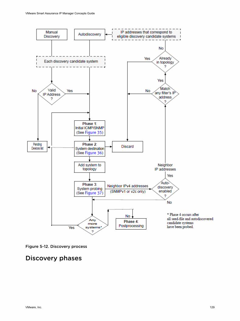
Figure 5-12. Discovery process
Discovery phases
VMware Smart Assurance IP Manager Concepts Guide
VMware, Inc. 129
The discovery is divided into four phases, shown in #unique_238/unique_238_Connect_42__IP_CONCEPTS_DISCOVERY_95824, that are performed sequentially foreach discovery candidate system:
1 Perform initial polling of the candidate system
2 Determine the destination of the candidate system: add to topology, place on Pending Devices list, ordiscard
3 Probe the system that is added to the topology
4 Post-process the discovery information
Note The VMware Smart Assurance IP Manager User Guide provides information on how toprepare for and initiate discovery.
Phase 1: Perform initial polling of the candidate system
Discovery for each discovery candidate system begins with a hostname or an IP address, which isprovided by the user or automatically discovered. The discovery process resolves the hostname to one ormore IP addresses through the local name resolution service. An IP address may be IPv4 or IPv6.
During the first phase of the discovery process, shown in Phase 1: Initial polling of a candidate system,the discovery process sends an ICMP request to determine if the discovery candidate system isreachable, and then sends an SNMP request to identify the system.
VMware Smart Assurance IP Manager Concepts Guide
VMware, Inc. 130
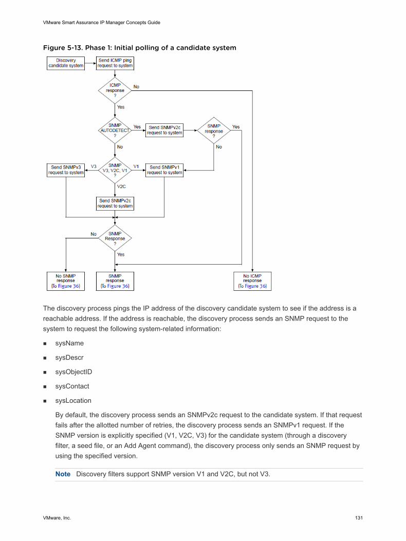
Figure 5-13. Phase 1: Initial polling of a candidate system
The discovery process pings the IP address of the discovery candidate system to see if the address is areachable address. If the address is reachable, the discovery process sends an SNMP request to thesystem to request the following system-related information:
n sysName
n sysDescr
n sysObjectID
n sysContact
n sysLocation
By default, the discovery process sends an SNMPv2c request to the candidate system. If that requestfails after the allotted number of retries, the discovery process sends an SNMPv1 request. If theSNMP version is explicitly specified (V1, V2C, V3) for the candidate system (through a discoveryfilter, a seed file, or an Add Agent command), the discovery process only sends an SNMP request byusing the specified version.
Note Discovery filters support SNMP version V1 and V2C, but not V3.
VMware Smart Assurance IP Manager Concepts Guide
VMware, Inc. 131
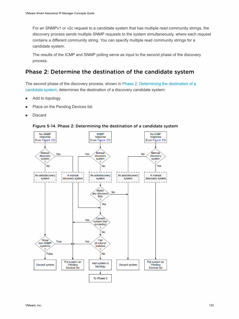
For an SNMPv1 or v2c request to a candidate system that has multiple read community strings, thediscovery process sends multiple SNMP requests to the system simultaneously, where each requestcontains a different community string. You can specify multiple read community strings for acandidate system.
The results of the ICMP and SNMP polling serve as input to the second phase of the discoveryprocess.
Phase 2: Determine the destination of the candidate system
The second phase of the discovery process, shown in Phase 2: Determining the destination of acandidate system, determines the destination of a discovery candidate system:
n Add to topology
n Place on the Pending Devices list
n Discard
Figure 5-14. Phase 2: Determining the destination of a candidate system
VMware Smart Assurance IP Manager Concepts Guide
VMware, Inc. 132
As shown in Phase 2: Determining the destination of a candidate system, the destination of thecandidate system depends on many factors, including:
n Whether the candidate system is an autodiscovery or manual candidate system
n Whether the system passes ICMP or SNMP polling
n Whether the system matches a discovery filter
n Whether the current system limit is exceeded
n Whether any volume licenses are available
n Whether ShowPendingNONSNMP in the BASEDIR/smarts/conf/discovery/discovery.conf file is set toTRUE
Factors that affect the destination of a candidate system summarizes how these factors determine thedestination of a candidate system when sufficient volume licenses are available.
Table 5-9. Factors that affect the destination of a candidate system
Candidatesystem
Initial polling Matchfilter
Current systemlimit exceeded 1
ShowPendingNONSNMP DestinationICMP SNMP
Autodiscovery Passed Passed Yes No Not applicable Topology
Yes Not applicable Pending Deviceslist
No Not applicable Not applicable Discard
Failed Notapplicable
Not applicable TRUE Pending Deviceslist
FALSE (default) Discard
Failed Notapplicable
Notapplicable
Not applicable Not applicable Discard
ManualDiscovery
Passed Passed Notapplicable
No Not applicable Topology
Yes Not applicable Pending Deviceslist
Failed Notapplicable
Not applicable Not applicable Pending Deviceslist
Failed Notapplicable
Notapplicable
Not applicable Not applicable Pending Deviceslist
1 50 by default. The VMware Smart Assurance IP Manager User Guide provides information on how to change the default.
The “Match filter” column in the table pertains to the matching of discovery-filter criteria other than “IPaddress.” An autodiscovery candidate system is subjected to two levels of discovery-filter matching:initially, a matching of IP address, and then a matching of other criteria after the candidate system passesICMP or SNMP polling. The two levels of discovery-filter matching are described in VMware SmartAssurance IP Manager User Guide.
VMware Smart Assurance IP Manager Concepts Guide
VMware, Inc. 133
If a candidate system cannot be discovered and is not discarded, the IP Manager places the system onthe Pending Devices list. The Pending Devices list is described in Pending Devices list.
Phase 3: Probe the system added to the topology
During the third phase of the discovery process, shown in Phase 3: Probing the system added to thetopology (Sheet 1 of 2), each system that is destined for the topology is probed to gather additionalinformation about the system, which includes the system’s components (such as cards, ports, interfaces,and so on), IP addresses, VLAN membership, environment sensors, system resources (such as memory,CPU, and so on), IP networks, netmasks, and neighboring systems. The IP Manager uses thisinformation to create the topology for the system.
VMware Smart Assurance IP Manager Concepts Guide
VMware, Inc. 134
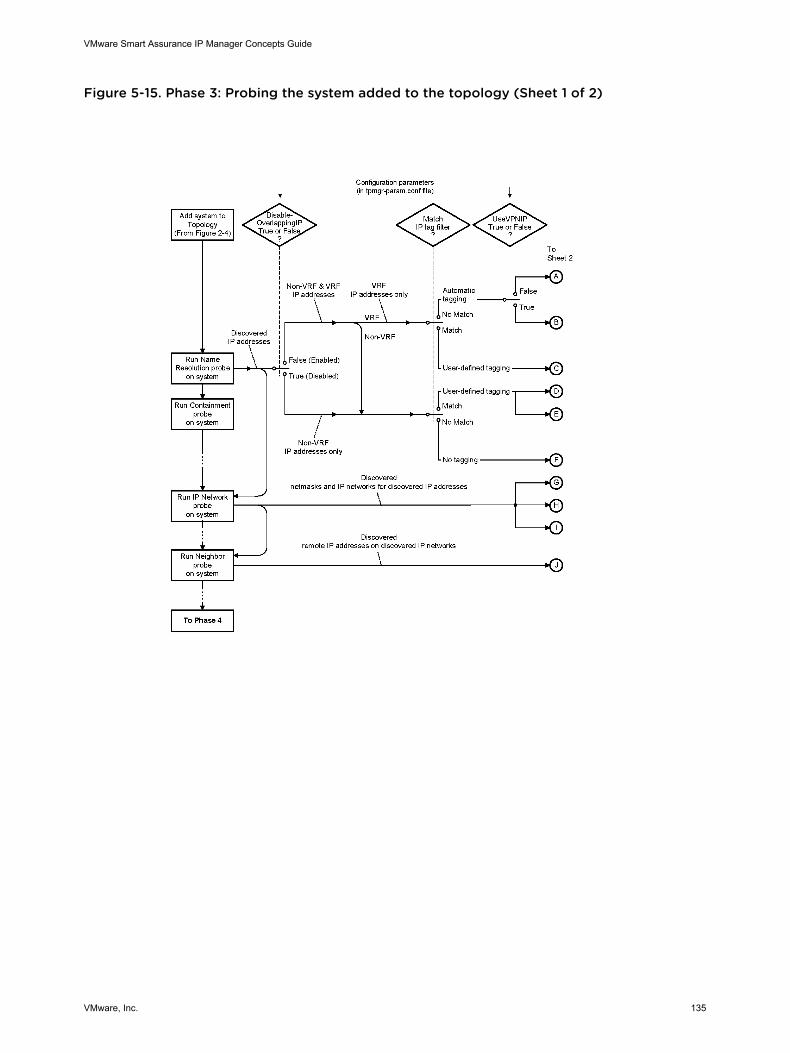
Figure 5-15. Phase 3: Probing the system added to the topology (Sheet 1 of 2)
VMware Smart Assurance IP Manager Concepts Guide
VMware, Inc. 135
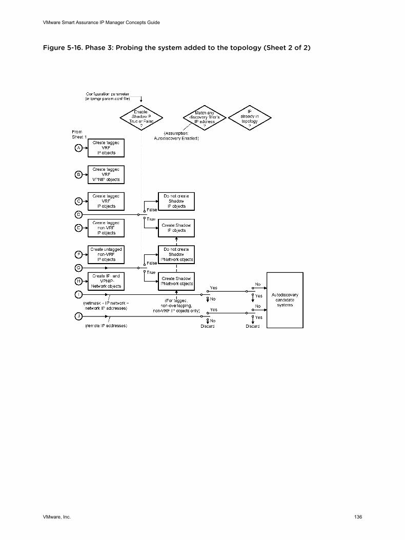
Figure 5-16. Phase 3: Probing the system added to the topology (Sheet 2 of 2)
VMware Smart Assurance IP Manager Concepts Guide
VMware, Inc. 136
Among other things, the network IP addresses that are formed from the discovered IP networks andnetmasks serve as input to the autodiscovery process. Autodiscovery, if enabled, will compare each ofthese IP addresses against one or more discovery filters and add each IP address that matches a filter tothe discovery queue. Discovery filters are described in the VMware Smart Assurance IP Manager UserGuide
Note Autodiscovery is available for IPv4 systems that have SNMPv1 or v2c agents.
The discovery process uniquely identifies the system within the topology and determines the system’slevel of certification. These tasks are accomplished by using the sysName, sysDescr, and sysObjectIDinformation retrieved from the initial SNMP poll.
oid2type configuration files
The discovery process matches the sysObjectID to an OID in the oid2type configuration files to identify:
n System’s type (Host, Router, Switch, and so on), vendor, model, and certification level.
n Which discovery drivers to use to probe the system.
n Which instrumentation classes to use to monitor the system.
The discovery process searches for the drivers in the .import files, which are located in the BASEDIR/smarts/conf/discovery directory as the oid2type files.
Certification
Certification is a process by which VMware, Inc. ensures that the devices that are managed by the IPManager are properly represented in the modeled topology, and that the devices are correctly monitoredfor connectivity and performance analysis. Devices are specific models of systems.
The certification process consists of three major parts:
n Discovery of the device, including the device’s components (such as cards, ports) and endpoints(such as IP addresses, MAC addresses)
n Building of Layer 2 (data link) and Layer 3 (network) connectivity
n Verification of operational status of the device and its components
The VMware Smart Assurance IP Certification Matrix identifies the vendor-specific models that aresupported by the IP Manager.
Certification levels
A device may have one of three certification levels:
n CERTIFIED — VMware, Inc. has successfully tested a simulation of the device by using standard andproprietary MIBs that are supplied by the vendor.
The IP Manager discovers the device by using standard MIB-II data and proprietary MIBs.
VMware Smart Assurance IP Manager Concepts Guide
VMware, Inc. 137
n TEMPLATE — VMware, Inc. assumes that the device supports some standard and proprietary MIBs,but VMware, Inc. has not tested the device.
The IP Manager recognizes the object ID (OID), but has no information about the MIBs that thisdevice supports.
All field-certified devices are assigned a TEMPLATE certification level.
n GENERIC — VMware, Inc. does not have the OID for the device.
The IP Manager does not recognize the OID and responds by classifying the certification level of thedevice as GENERIC, adding the device to the Node class, and analyzing the device by using MIB-IIdata.
Note A certification level named VALIDATED still appears in the oid2type configuration files but is nolonger used. VALIDATED has essentially the same meaning as CERTIFIED.
Standard and proprietary MIBs
The IP Manager uses proprietary MIBs in addition to standard MIBs because standard MIBs do notalways contain the information that is needed by the IP Manager to discover and manage certain objects.Standard MIBs, for example, do not represent the processor or memory objects that are necessary forperformance analysis. In these cases, proprietary MIBs offer more detailed information.
Note Proprietary MIBs are also known as enterprise, vendor-specific, or private MIBs. Standard MIBsare also known as generic MIBs.
Discovery probes and drivers
The probing of topology is accomplished by using the discovery drivers that are identified in thefollowing .import files:
BASEDIR/smarts/conf/discovery/DISCOVERY_<vendor>.import
BASEDIR/smarts/conf/discovery/DISCOVERY_CUSTOM.import
The main drivers are identified in the DISCOVERY_<vendor>.import files, and the custom drivers, alsoknown as discovery hook scripts, are identified in the DISCOVERY_CUSTOM.import files. VMware SmartAssurance IP Manager User Guide provides information about the custom drivers. By default, the customdrivers are not configured and therefore do not run.
The discovery process calls the discovery probes that are listed in Discovery probes, in the order that theprobes are listed. Each probe will call one or more discovery drivers.
VMware Smart Assurance IP Manager Concepts Guide
VMware, Inc. 138
Table 5-10. Discovery probes
Probe name 1 Applicable to these systems Available to these IP Manager products
1 Not all probes are listed in this table.
2 Performance probes and Host Resources probes are also known as Health probes.
3 Requires a feature license to enable the Performance probe.
4 Requires a feature license to enable the Host Resources probe.
Name Resolution All systems All IP Manager products
Containment All systems All IP Manager products
VLAN Bridges, switches All IP Manager products
Bridge Bridges, switches All IP Manager products
HSRP Routers All IP Manager products
VRRP Routers All IP Manager products
IP Network All systems All IP Manager products
Virtual Router Routers, switches All IP Manager products
Neighbor All systems All IP Manager products
Performance 2 All systems IP Availability and Performance Managerrunning as a single process,
IP Performance Manager 3,IP ServerPerformance Manager 3
Host Resources 2 All systems IP Server Performance Manager 4
The actual probes and associated discovery drivers that run for a specific device are specified in theoid2type configuration files. A specific device is identified by a unique OID. If a probe is not specified for aspecific device, the IP Manager skips the probe.
The probes operate in series, one immediately following the other. In the event that one of the discoveryprobes is unable to complete, the discovery process does not stop. Instead, discovery proceeds with thenext probe. Events that can prevent a discovery probe from completing are discussed in Discovery errorscenarios and results.
Name Resolution probe
The Name Resolution probe calls multiple drivers, including:
n A driver that gathers IPv4 and IPv6 addresses and other MIB-II data for the system.
n A driver that gathers VPN routing and forwarding (VRF) IP addresses and route distinguisher tagsfrom individual vendor MIBs on the system.
n A driver that provides a unique name for the system, as described in How discovery names a system.
The Name Resolution probe discovers almost all of the IP and IPv6 addresses that are available forthe system, including the VRF IP addresses if the DisableOverlappingIP configuration parameter isset to FALSE. Matrix of IP-related objects created by the Name Resolution probe summarizes the IP-related objects that are created by the Name Resolution probe.
VMware Smart Assurance IP Manager Concepts Guide
VMware, Inc. 139
Table 5-11. Matrix of IP-related objects created by the Name Resolution probe
Configuration parameters in tpmgr-param.conf file
VRF IP addresses discovered? Shadow IP objects created?DisableOverlappingIP EnableShadowIP
1 Shadow IP objects are created only for tagged, non-overlapping, non-VRF IP objects.
VRF IP addresses
TRUE (default) Don’t care No Not applicable
FALSE Don’t care Yes No
Non-VRF IP addresses
Don’t care TRUE (default) Not applicable Yes 1
Don’t care FALSE Not applicable No
IP object tagging
All VRF and non-VRF IP objects that are created by the Name Resolution probe are subject to user-defined IP tagging assuming that the DisableOverlappingIP parameter is set to FALSE. The VMwareSmart Assurance IP Manager User Guide provides instructions on creating IP tag filter groups andexplains the naming scheme for applying tags to IP objects.
The IP objects have a Tag attribute. For a tagged IP object, the Name Resolution probe sets the Tagattribute to the object’s tag value. For an untagged IP object, the Name Resolution probe leaves the Tagattribute empty.
Shadow IP object creation
When the EnableShadowIP parameter is set to TRUE (default), the Name Resolution probe creates ashadow IP object for each tagged, non-overlapping, non-VRF IP object. The probe uses the followingnaming scheme to name the shadow IP object:
IP-<IP address>
(Display name: [Shadow]:<IP address> [<system containing this IP>])
where <IP address> is the IP address of the IP object that the shadow IP object is shadowing.
The Name Resolution probe sets the IsShadow attribute of the shadow IP object to TRUE, to identify theobject as a shadow IP object. The probe also creates a ShadowOf relationship between the shadow IPobject and the IP object that is being shadowed.
Refer the VMware Smart Assurance IP Manager User Guide for more information on shadow IP objects.
Duplicate IP object creation
If no IP tagging is in effect and the Name Resolution probe finds an IP address that is already in themodeled topology, the probe responds as follows:
n Discards the overlapping IP address
n Removes the initially received overlapping IP address from the topology
VMware Smart Assurance IP Manager Concepts Guide
VMware, Inc. 140
n Creates a DuplicateIP object
For a similar scenario in an IPv6 network, the Name Resolution probe will discard the overlappingIPv6 address, remove the initially received overlapping IPv6 address from the topology, and create aDuplicateIPv6 object.
IP address and MIB information distribution
All IP address and MIB information that is gathered by the Name Resolution probe for the discoveredsystem is made available to all other discovery probes, including the IP Network probe.
Containment probe
The Containment probe discovers the components of a system, including ports, interfaces, MACendpoints, and any cards or modules. It queries the following MIB variables:
n ifType
n ifDescr
n ifSpeed
n ifMtu
n ifPhysAddress
n ifAlias
n ifName
n Other variables
If the Containment probe has access to vendor-specific MIBs, it queries additional variables to gatheradditional information, such as:
n Duplex mode (full-duplex, half-duplex) of ports and interfaces.
n Data link connection identifiers (DLCIs) for Frame Relay virtual connections.
n NIC-teaming ports and interfaces for teamed connections, as described in Discovery of NIC teaming.
n IPSec and Internet Key Exchange (IKE) interfaces for IPSec and IKE tunnels, as described in Supportfor IPSec and IKE tunnels.
n Virtual and real IP address and port information for load balancer virtual connections.
For bridges or switches, the Containment probe might also query the dot1dBasePortIfIndex MIBvariable.
VLAN probe
The VLAN probe collects VLAN information for a discovered bridge or switch, including VLAN identifiers,VLAN trunks, VLAN trunk ports, and VLAN port memberships. It uses vendor-specific MIB information.
The VLAN probe creates VLAN objects and Port or Interface object VLAN members, and uses the PartOf/ComposedOf relationship to associate the VLAN objects with their VLAN members.
VMware Smart Assurance IP Manager Concepts Guide
VMware, Inc. 141
All VLAN objects that are created by the VLAN probe are subject to user-defined VLAN tagging, whichensures that bridges and switches are assigned to the appropriate VLAN. The VMware Smart AssuranceIP Manager User Guide provides instructions on creating VLAN tag groups, and explains the namingscheme for applying tags to VLAN objects.
Bridge probe
The Bridge probe collects bridge-forwarding tables and Spanning Tree Protocol (STP) information for adiscovered bridge or switch. Discovery uses this information to create MAC objects, and to build thebridging relationships between MAC endpoints and ports. The Bridge probe uses standard and vendor-specific MIB information.
One Bridge probe is run for each VLAN that is discovered on a bridge or switch, to gather the bridge-forwarding and STP information for the VLAN.
HSRP probe
The HSRP probe collects information from a redundancy group of routers that are involved in an HSRPgroup. The routers use the proprietary Cisco Hot Standby Router Protocol to communicate with oneanother. The HSRP probe discovers the group number, the virtual IP address, and the virtual MACaddress for an HSRP group; the priority number and status for each router endpoint that is participating inthe group; and the currently active router in the group. The HSRP probe uses vendor-specific MIBinformation.
The HSRP probe creates HSRPGroup objects and HSRPEndpoint objects.
VRRP probe
The VRRP probe collects information from a redundancy group of routers that are involved in a VRRPgroup. The routers use the industry standard Virtual Router Redundancy Protocol to communicate withone another. The VRRP probe discovers the group number, the virtual IP address, and the virtual MACaddress for a VRRP group; the priority number and status for each router endpoint that is participating inthe group; and the currently active router in the group. The VRRP probe uses standard MIB informationand creates VRRPGroup objects and VRRPEndpoint objects.
IP Network probe
For an IPv4 system, the IP Network probe examines the system’s IP address table (ipAddrTable) tocombine the IP addresses and the netmask for each interface on the system to create IPNetwork objects,and to build the connected relationships between IP endpoints and IP networks.
For an IPv6 system, the IP Network probe examines the system’s IP address table to create IPv6Networkobjects, and to build the connected relationships between IPv6 endpoints and IPv6 networks.
For a dual-stack system, the IP Network probe examines the system’s IP address table to createIPNetwork and IPv6Network objects, to build the connected relationships between IP endpoints and IPnetworks, and to build the connected relationships between IPv6 endpoints and IPv6 networks.
The IP Network probe uses standard MIB-II information to discover IP addresses.
VMware Smart Assurance IP Manager Concepts Guide
VMware, Inc. 142
The IP Manager attempts to discover and monitor IPv6 addresses on devices that implement andpopulate either of the following MIBs:
n IPV6-MIB (.1.3.6.1.2.1.55)
or
n CISCO-IETF-IP-MIB (.1.3.6.1.4.1.9.10.86)
For devices that are implementing other MIBs, the IP Manager discovers and monitors only IPv4addresses.
IPNetwork object tagging
All VRF and non-VRF IPNetwork objects that are created by the IP Network probe are subject to user-defined IP tagging assuming that the DisableOverlappingIP parameter is set to FALSE. The VMwareSmart Assurance IP Manager User Guide provides instructions on creating IP tag filter groups andexplains the naming scheme for applying tags to IP objects and IPNetwork objects.
The IPNetwork objects have a Tag attribute. For a tagged IPNetwork object, the IP Network probe setsthe Tag attribute to the object’s tag value. For an untagged IPNetwork object, the IP Network probe leavesthe Tag attribute empty.
Shadow IPNetwork object creation
When the EnableShadowIP parameter is set to TRUE (default), the IP Network probe creates a shadowIPNetwork object for each IPNetwork object to which a tagged, non-overlapping, non-VRF IP object is“ConnectedVia.” The probe uses the following naming scheme to name the shadow IPNetwork object:
IPNET-<IP network>
(Display name: [Shadow]:<IP network>)
where <IP network> is the IP network of the IPNetwork object that the shadow IPNetwork object isshadowing.
The Name Resolution probe sets the IsShadow attribute of the shadow IPNetwork object to TRUE toidentify the object as a shadow IPNetwork object. The probe also creates a ShadowOf relationshipbetween the shadow IPNetwork object and the IPNetwork object that is being shadowed.
Autodiscovery IP address formation
The IP Network probe also combines each discovered IP network with its netmask to form network IPaddresses, for input to the autodiscovery process. For example, consider the IP network 192.168.71.0that has a netmask of 255.255.255.0. The IP Network will create network IP addresses in the range192.168.71.<1-254> for this IP network and netmask. Any network IP address that matches a discoveryfilter and is not already in the modeled topology becomes an autodiscovery candidate system.
Virtual Router probe
VMware Smart Assurance IP Manager Concepts Guide
VMware, Inc. 143
The Virtual Router probe discovers the virtual routers in an IPv4 physical router or switch that containsvirtual routers. The Virtual Router probe discovers the following additional information: the physical cardon which the virtual router resides, if such information is available, and the virtual router’s interfaces andtheir associated physical ports. The Virtual Router probe uses vendor-specific MIB information.
The Virtual Router probe creates a Router object for the physical router and for each virtual router, andcreates a Switch object for the physical switch. The probe uses the ComposedOfVRs relationship toassociate the virtual-router objects with the physical-router or physical-switch object.
Neighbor probe
The Neighbor probe collects information about a system’s neighbors. It reads Cisco Discovery Protocol(CDP) tables, Extreme Discovery Protocol (EDP) tables, Foundry Discovery Protocol (FDP) tables, andother tables to discover remote addresses on the already discovered networks, and to discover ATMinformation. The Neighbor Probe uses vendor-specific MIBs.
The Neighbor probe passes the remote IP addresses to the autodiscovery process, which adds the IPaddresses to its list of potential discovery candidate systems. The probe does not create IP objects forthe remote IP addresses.
The discovery process checks to see if any of the remote IP addresses correspond to IP objects that arealready in the repository. The discovery process will use this information during the final phase ofdiscovery to create cable, trunk cable, and network connections.
Performance probe
The Performance probe collects performance-related information for system objects such as ports,interfaces, processors, memory, fans, power supplies, voltage sensors, and temperature sensors. ThePerformance probe uses standard and vendor-specific MIB information.
The Performance probe creates Processor, Memory, Fan, PowerSupply, VoltageSensor, andTemperatureSensor objects, and monitors statistics for the objects. For Port and Interface objects, whichare created by the Containment probe, the performance monitoring might be the utilization that is basedon the octets that are received and transmitted. For Memory objects, the performance monitoring mightbe the total amount of available memory, the total number of overrun buffers, and so on.
Host Resources probe
The Host Resources probe collects additional performance-related information for system objects. Itcollects metrics about host disks and file systems, as well as additional information about host processorsand memory. The Host Resources probe uses standard and vendor-specific MIB information.
The Host Resources probe creates Disk and File System objects, and monitors statistics for the objects. Italso monitors additional statistics for the Processor and Memory objects that are created by thePerformance probe.
Discovered SNMP agent
VMware Smart Assurance IP Manager Concepts Guide
VMware, Inc. 144
In addition to discovering the system, the discovery process also discovers the system’s SNMP agent andadds it to the modeled topology. The discovery process sets the following attributes for the SNMPAgentobject:
n Sets the AgentAddress attribute to the IP address that is used by the initial ICMP poll to reach thesystem.
n Sets the AgentAddressList attribute to a list of IP addresses that are discovered on the system.Included in the list is the IP address that is set for the AgentAddress attribute.
The order of addresses in the list is controlled by the DiscoveryAddrPref and AccessAddressFormatparameters in the discovery.conf file. The DiscoveryAddrPref parameter places the preferred versionof addresses (IPv6 or IPv4) at the beginning of the list. And within a list of IPv6 or IPv4 addresses, theAccessAddressFormat parameter places the preferred types of addresses (loopback, Ethernet, andso on) at the beginning of the list.
n Sets the PortNumber attribute (161 by default) to the port number that is used by the first SNMP pollto successfully communicate with the SNMP agent.
n Sets the SNMPVersion attribute (AUTODETECT by default) to the version that is used by the firstSNMP poll to successfully communicate with the SNMP agent.
n SNMPv1 or v2c only: Sets the ReadCommunity attribute (public by default) to the read communitystring that is used by the first SNMP poll to successfully communicate with the SNMPv1 or v2c agent.
n SNMPv3 only: Sets the attributes that are shown in Values used in SNMP polling to the values thatare used by the first SNMP poll to successfully communicate with the SNMPv3 agent.
Table 5-12. Values used in SNMP polling
Attribute Description
1 Retrieved from the SNMP polling of this SNMPv3 agent.
User Name of user that is included in the SNMP request that is sent to this SNMPv3 agent.
AuthPass Password that is used as the basis for the following: The creation of the localized authentication key thatis used with the selected authentication protocol and this SNMPv3 agent. The password is required ifthe authentication protocol is MD5 or SHA.
The password may be encrypted (recommended) or appear as plain text.
AuthProtocol Protocol that is used to authenticate the SNMP request that is sent to this SNMPv3 agent: MD5, SHA,or NONE (default).
PrivPass Password that is used as the basis for the following: The creation of the localized encryption key that isused with the selected privacy protocol and this SNMPv3 agent. The password is required if the privacyprotocol is DES or AES.
The password may be encrypted (recommended) or appear as plain text.
PrivProtocol Protocol that is used to encrypt the SNMP request that is sent to this SNMPv3 agent: DES, AES, orNONE (default).
EngineID Identifier that uniquely identifies the SNMP engine of this SNMPv3 agent; for example,800002b804616263.
VMware Smart Assurance IP Manager Concepts Guide
VMware, Inc. 145
Attribute Description
EngineBoots 1 Number of times that the SNMP engine of this SNMPv3 agent has initialized or reinitialized since its lastconfiguration.
EngineBootTime 1 Date and time that the SNMP engine of this SNMPv3 agent last initialized or reinitialized.
n Sets the sysName, sysDescr, sysObjectID, sysContact, and sysLocation attributes to the sysName,sysDescr, sysObjectID, sysContact, and sysLocation values that are retrieved from the first SNMPpoll to successfully communicate with the SNMP agent.
n Sets many other SNMP agent attributes in accordance to the values that are found by the discoveryprobes.
Discovered VR agents
For a physical router or switch that contains virtual routers, the discovery process also discovers the VRagents for the virtual routers. Because VRAgent is a subclass of SNMPAgent, the attributes of a VR agentare the same as the attributes of an SNMP agent with the following exception: The VR agent has anadditional attribute called RouterID.
Discovered topology collection sets
For satellite Domain Managers, the discovery process also discovers and creates the topology collectionsets that are described in the VMware Smart Assurance IP Manager Reference Guide. By default, thecreation of Domain Manager topology collection sets is disabled.
Phase 4: Post-process the discovery information
After an IP Manager probes all seed-file and autodiscovered candidate systems, it performspostprocessing. Postprocessing tasks include the reconciliation of system data objects and the clean upof chassis, SNMPAgent, IP, IPv6, and DuplicateIP objects. The message “Postprocessing topology ...”displayed in the Discovery Status section of an IP Manager’s Discovery Progress window indicates whenpostprocessing tasks are in progress.
The postprocessing code in the IP Manager creates Layer 2 (data link) and Layer 3 (network) connectivitybetween the systems in the topology. The code bases the connectivity on IP networks, standardprotocols, and vendor-specific discovery protocols.
The postprocessing functions that are performed by the IP Manager include:
n Mapping IP, IPv6, and MAC endpoints in the Address Resolution Protocol (ARP) cache to theappropriate systems. For non-SNMP systems, create IP, IPv6, and MAC endpoints and layer themover a physical interface. Because non-SNMP systems are discovered, the postprocessing codecreates an artificial physical interface for each IP (v4 or v6) address that is associated with thesystem.
n Removing MAC endpoints that do not belong to any systems in the topology. Any MAC endpoint thatis bridged by a port but is not hosted by any system is removed.
VMware Smart Assurance IP Manager Concepts Guide
VMware, Inc. 146
n Managing ports. Any port that is BridgedVia a MAC is set to managed.
n Converting IP objects to DuplicateIP objects. Any IP object that is discovered is converted to aDuplicateIP object.
n Converting IPv6 objects to DuplicateIPv6 objects. Any IPv6 object that is discovered is converted to aDuplicateIPv6 object.
n Resolving duplicate devices, as explained in VMware Smart Assurance IP Manager User Guide.
n Creating connections by using the collected bridge-forwarding information: create cables betweenports and interfaces, create trunk cables between ports, and remove MAC endpoints that are bridgedby access ports from the BridgedVia relationships of other ports.
n Creating trunk cables by using the collected Spanning Tree Protocol (STP) information.
n Creating network connections to represent WAN, or logical, connections.
n Creating any user-defined connections that are specified in the user-defined-connections.conf file.
n Creating partitions and naming them in accordance to the names that are specified in the user-defined partition.conf file.
n Creating redundancy group objects by combining group-member objects.
n Setting the DisplayNames for the discovered objects.
The user-defined-connections.conf and partition.conf files are located in the BASEDIR/smarts/conf/discovery directory. The VMware Smart Assurance IP Manager Reference Guide describes theconfiguration parameters in these files and provides instructions on modifying the parameters.
More about the managing of ports
All ports that are imported are unmanaged.
The IP Manager sets a port to managed if the port has a connection. The port may be a trunk port or anaccess port. The IP Manager imports only those ports that are managed.
Furthermore, the IP Manager imports only managed objects and performs correlation and root-causeanalysis on managed objects only. Managed and unmanaged objects are described in the VMware SmartAssurance IP Manager User Guide.
More about the conversion of IP objects to DuplicateIP objects
If multiple instances of the same IP address exist within the IP Manager domain, and when the IPManager imports and merges the topologies, it replaces the multiple IP objects with a single DuplicateIPobject. For a similar scenario in an IPv6 network, the IP Manager replaces the multiple IPv6 objects with asingle DuplicateIPv6 object.
Information on how to handle DuplicateIP address notifications are described in the VMware SmartAssurance IP Manager User Guide.
More about the creation of redundancy groups
VMware Smart Assurance IP Manager Concepts Guide
VMware, Inc. 147
A redundancy group is a logical object that contains two or more objects that participate in a redundantconfiguration. Examples of redundancy groups are CardRedundancyGroup, HSRPGroup, VRRPGroup,and SystemRedundancyGroup.
IP Manager automatically creates CardRedundancyGroups during discovery for Cisco devices thatsupport the CISCO-STACK-MIB. Each such group consists of two cards. You can view the cardredundancy groups and their members by using the Domain Manager Administration Console. Inaddition, you can create redundancy groups for cards that do not support the CISCO-STACK-MIB.
Redundancy groups for network adapters, network connections, and systems must be manually createdby using the dmctl utility or an Adapter Scripting Language (ASL). Network adapter, network connection,and system redundancy groups can be viewed through the Domain Manager Administration Console orthe Topology Browser view of the Global Console.
During discovery, IP Manager automatically creates HSRPGroups for Cisco devices that support theCISCO-HSRP-MIB and are configured in an HSRPGroup. Each such group is composed of two or morerouters and their interfaces. Also during discovery of the VRRP enabled routers, IP Manager creates anew redundancy group called VRRPGroup.
The VMware Smart Assurance IP Manager Reference Guide describes the redundancy group classesthat can be instantiated by the IP Manager.
IP 8.1.1 discovers and monitors routers in VRRP configurations. Devices supported are Nortel devices, alldevices which implement RFC 3768, Juniper ERX 700, 1400, 310, 320, and Nortel Alteon ACEdirector 4.VRRP discovery is enabled by default in IP 8.1.1 in the discovery.conf file (VRRPEnabled = TRUE).
The VMware Smart Assurance IP Manager User Guide provides more information on creation ofredundancy groups.
Autodiscovery data sources
The Name Resolution, IP Network, and Neighbor probes contact the autodiscovery data sources togather the topology and IP address table (ipAddrTable) MIBs of the seed systems to determine what othersystems are known to the seed systems. As these systems are discovered by autodiscovery, they too areprobed for candidate systems.
The autodiscovery process uses three different sources of information to discover candidate systems:
n Topology MIB
n IP address table MIB
n ARP table MIB
By default, autodiscovery uses the topology and IP address table MIBs of the discovered systems(initially, of the discovered seed systems) because the MIBs are very reliable sources for topologyinformation. The procedure for adding the ARP table MIB as a data source is presented in theVMware Smart Assurance IP Manager User Guide.
Topology MIBs data source
VMware Smart Assurance IP Manager Concepts Guide
VMware, Inc. 148

Topology MIBs are an important data source for discovering neighboring systems. When the topologyMIB data source is enabled, autodiscovery uses the IP addresses from these sources to discover relatedsystems. Examples of topology MIB data sources include the following:
n IP addresses stored in the Cisco Discovery Protocol (CDP) table
n IP addresses stored in the MIB-II atmInterfaceConfTable table
In some cases, however, a system is not discovered for each IP address, if, for example, there is noroute to the network from the host on which the IP Manager is running. This situation can occur whensecurity restrictions are designed to prevent access between two separate networks.
IP address table MIB data source
The MIB-II IP address table lists all the IP interfaces of the system that is being discovered, as well as thesubnet masks associated with these IP networks. By using this information, autodiscovery derives all ofthe possible IP addresses within each subnet. The Name Resolution probe pings each of theseaddresses to find candidate systems for subsequent SNMP probing.
ARP table MIB data source
The MIB-II ARP table provides a mapping of IP addresses to MAC addresses for any neighboring systemthat has recently communicated with the system with this MIB. However, because the ARP MIB ispopulated only when the system resolves the addresses of neighboring systems that are connected witha broadcast network protocol such as Ethernet, the ARP MIB is not appropriate for use in WANs, whichtypically use a non-broadcast protocol.
Discovery of NIC teaming
The IP Manager discovers and monitors network interface card (NIC) teaming between hosts andswitches. NIC teaming provides network access redundancy and allows for rapid convergence when afailure occurs.
Note Setting up NIC teaming is device and vendor specific. Vendor specific documentation on how toset it up in a customer environment with different vendors is not provided here. For any device or vendorspecific setup information, refer the relevant vendor specific documentation.
NIC teaming
NIC teaming is the grouping of two or more physical network interface cards (NICs) into a single logicalNIC, for the purpose of achieving either or both of the following ends:
n Network fault tolerance
High availability is maximized by binding two or more physical NICs to a logical NIC. If a NIC fails, thenetwork connection continues through another NIC.
n Network traffic load balancing
VMware Smart Assurance IP Manager Concepts Guide
VMware, Inc. 149
Balancing the network traffic load on a server enhances the functionality of the server and thenetwork. The traffic is distributed amongst the members of a NIC team so that the traffic is routed onall of the teamed connections.
While NIC teaming is possible for a number of different media types, the primary focus of the NICteaming feature in IP Manager is Ethernet-media devices. In addition, for load balancing, the followingconditions are assumed:
n The teamed connections terminate on the same remote device.
n The remote device is configured with an EtherChannel or an equivalent port-trunking protocol.
A teamed NIC can have as many as eight NICs.
In the IP Manager, NIC teaming support is applicable specifically to device specific discovery andoccurs at three different points which are IP Availability Manager initialization, oid2Type configuration,and Discovery probes.
In a team of two or more NICs, the secondary NIC assumes the primary or active role, if the primaryNIC fails. Failover will not occur unless the primary NIC is specified. The NIC with the highestsupported speed is chosen as the primary NIC. If more than one NIC runs at the highest supportedspeed, the last of these NICs added to the team becomes the primary. The NIC teaming functionalityprovides network access redundancy monitoring.
NIC teaming discovery is enabled by default in the tpmgr-param.conf file(EnableTeamedNICDiscovery =TRUE). Discovery of Interfaces on Hosts is impacted due to supportfor NIC teaming discovery (for devices having OID .1.3.6.1.4.1.311.1.1.3.1.*).
Upon discovery of the device (host) that is configured for NIC teaming, a redundancy groupNetworkAdapterRedundancyGroup is created in the IP Manager. If theNetworkAdapterRedundancyGroup (NARG) is not created, either the EnableTeamedNICDiscoveryflag is set to FALSE or the Host may be of a different vendor type other than Broadcom, Intel, or HP.
Note The VMware Smart Assurance IP Manager Reference Guide provides more information onNIC teaming including attributes, root cause problems, and events for theNetworkAdapterRedundancyGroup.
Discovery MIBs
By probing the standard MIB-II tables on a host that employs a teamed NIC, the IP Manager discoversthe logical NIC, but does not discover the physical NIC information that it needs to create the Layer 2connectivity between the host and the neighboring switch or switches. To collect the physical NICinformation, the IP Manager probes the enterprise MIBs on the host.
The collected physical NIC information contains the burned-in MAC (BIM) for each of the teamed-NICaccess ports. A BIM uniquely identifies a teamed-NIC access port. As an aside, a teamed-NIC accessport is not uniquely identified in the MIB-II tables; instead, in the MIB-II tables, all of the teamed-NICaccess ports are identified by the same logical MAC address.
VMware Smart Assurance IP Manager Concepts Guide
VMware, Inc. 150
By using the collected physical NIC information, the IP Manager creates an instance of theNetworkAdapterRedundancyGroup to represent the logical grouping of the physical NICs. Doing soenables the IP Manager to create the Layer 2 cable connections between the host and the neighboringswitch or switches.
Vendor support
The NIC teaming feature in IP Manager supports the following vendors:
n Broadcom
n Intel
n Compaq/HP
Although a mixture of vendors (for example, Broadcom and Intel) can be involved in a teamed NIC,only single-vendor teamed NICs have been tested for IP Manager 8.1.1.
Redundancy group creation
Upon discovering a device that is configured for NIC teaming, the IP Manager creates an instance of theNetworkAdapterRedundancyGroup. A NetworkAdapterRedundancyGroup instance consists of two ormore ports or interfaces that participate in NIC teaming.
NetworkAdapterRedundancyGroup has a ComposedOf relationship with Interface, where the Interfaceclass is used to represent both teamed-NIC ports and interfaces. Interface has a PartOf relationship withNetworkAdapterRedundancyGroup.
The VMware Smart Assurance IP Manager Reference Guide provides more information about theNetworkAdapterRedundancyGroup, including its attributes and the events that the IP Manager generatesfor a NetworkAdapterRedundancyGroup.
Discovery and short discovery of IPSec tunnels
The IP Manager discovers IPSec tunnels and Internet Key Exchange (IKE) tunnels between IPSec-enabled routers on IPv4 networks. It uses Router, Interface, and IP object types to model the tunnels.
During a full discovery, the IP Manager reads the Routing Table of IPSec-enabled routers to discover theterminating subinterfaces (WAN endpoints) of IPSec tunnels and IKE tunnels. The IP Manager layers thesubinterfaces over the underlying physical interfaces and creates the network connections between thelocal and remote subinterfaces to form the IPSec and IKE tunnels.
By default, the IP Manager is not enabled to discover IPSec tunnels.
Refer the VMware Smart Assurance IP Manager User Guide on how to enable IPSec tunnel discoveryand also on how to modify parameters in the tpmgr-param.conf, discovery.conf, and the runcmd_env.shfiles.
Monitoring IPSec tunnels
VMware Smart Assurance IP Manager Concepts Guide
VMware, Inc. 151
The IP Manager monitors the tunnels by monitoring the IsDownOrFlapping attribute of the WAN Interfaceobjects that are associated with the tunnels. The WAN Interface objects represent the terminatingsubinterfaces of the tunnels.
Rediscovering IPSec tunnels
When the IP Manager detects a change in the IsDownOrFlapping attribute of a WAN interface that isassociated with a tunnel, it places the host router on the short discovery queue for a short discovery forthe following reason:
IPSec and IKE tunnels are dynamic in the sense that they can be rerouted to other WAN interfaces whenan interface fails. Therefore, when the IP Manager detects a change in the IsDownOrFlapping attribute, ithas no way of knowing whether the relationship between the tunnel and the associated WAN interface, asknown to the IP Manager, is still valid.
By updating the dynamic indices of the interfaces on the host router, the IP Manager is able to recreatethe tunnel association with the WAN interface.
Short discovery process
The short discovery process runs in parallel with the full discovery process and has its own discoveryqueue and its own timer interval. Short discovery process shows how the short discovery process works.
VMware Smart Assurance IP Manager Concepts Guide
VMware, Inc. 152
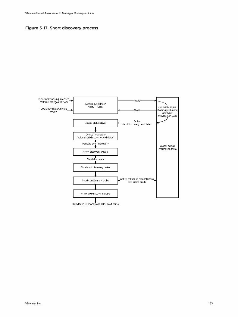
Figure 5-17. Short discovery process
VMware Smart Assurance IP Manager Concepts Guide
VMware, Inc. 153
IsDownOrFlapping interface attribute changes and OperationallyDown card events serve as input to theshort discovery process. Periodically, the device node table is scanned for short discovery candidates,and any candidates that are found in the table are placed on the short discovery queue. The shortdiscovery probes contact the candidates to update the dynamic indices of their interfaces and their cardsfor monitoring purposes.
Only the IsDownOrFlapping interface attribute changes pertain to IPSec tunnels and IPSec-enabledrouters. The OperationallyDown card events pertain to cards that reside in switches.
Short discovery characteristics
Short discovery has the following characteristics:
n The device node table in #unique_286/unique_286_Connect_42__IP_CONCEPTS_DISCOVERY_27007 is consulted frequently (every 900seconds, or 15 minutes, by default).
n Short discovery has its own short discovery threads, just as full discovery has its own discoverythreads. By default, the number of short discovery threads is 7.
n Short discovery is performed only on routers or switches that are already in the topology. Shortdiscovery of IPSec tunnels is performed on routers, and short discovery of cards is performed onswitches.
n Short discovery changes only the attributes of already discovered router or switch objects.
n Short discovery does not perform postprocessing or codebook recomputation.
Note The VMware Smart Assurance IP Manager User Guide provides information on how to enableshort discovery, change the short discovery interval, or the number of short discovery threads.
Analyzing IPSec tunnels
Here is a summary of how IPSec tunnels are discovered and monitored:
n The IP Manager discovers the WAN subinterface endpoints of the tunnels and layers them over theunderlying physical interfaces.
n The IP Manager monitors the tunnels by monitoring the IsDownOrFlapping attribute of thesubinterface endpoints that are associated with the tunnels and then creates the network connectionsbetween the local and remote subinterface endpoints to form the IPSec tunnels.
“Network adapters and device connections” on page 32 provides information about physicalinterfaces, subinterfaces, network connections, and WANs.
The IP Manager then uses the discovered physical interfaces, subinterfaces, and networkconnections, in conjunction with the subinterface statuses that are obtained from the monitoring of theIsDownOrFlapping attribute, to diagnose IPSec tunnel failures. For each physical interface, anddepending on the symptoms, the IP Manager diagnoses one or moreNetworkConnection::DownOrFlapping impact events, and diagnoses either an Interface::Downproblem or one or more NetworkConnection::Down problems:
VMware Smart Assurance IP Manager Concepts Guide
VMware, Inc. 154
n Interface::Down, if the physical interface is operationally down, which explains why all of thesubinterfaces that are layered over the physical interface have failed, along with any peer interfacesof those subinterfaces. “Interface” in “Interface::Down” represents the physical interface.
n NetworkConnection::Down, if the physical interface is operationally up, for each network connectionfailure at the subinterface level.
Network connections at the subinterface level represent WAN circuits that are carrying IPSec tunnels.
As a precondition for IPSec tunnel analysis, add the following line to the BASEDIR/smarts/conf/localruncmd_env.sh file:
SM_LOGICALCONNECTIONDOWN=DISABLED
The procedure and reason for completing this task are given in the VMware Smart Assurance IPManager User Guide. The Interface::Down problem, NetworkConnection::Down problem, andNetworkConnection::DownOrFlapping impact events are described in the VMware Smart AssuranceIP Manager Reference Guide.
Discovery and the local name resolution service
The discovery process uses the name resolution service that is provided by the local operating system totranslate hostnames to IP addresses, and to translate IP addresses to hostnames. On a UNIX system, aname resolution service might be Domain Name System (DNS), NIS or NIS+, or a hosts file. Importantinformation about name resolution services is presented in System hostname does not resolve to an IPaddress.
SM_IP_VERSIONS environment variable
If a discovery candidate system is presented as a hostname without an explicit IP version suffix(:v6v4, :v4v6, :v6, or :v4), the SM_IP_VERSIONS environment variable controls how the local nameresolution service resolves the hostname to a corresponding IP address. By default, SM_IP_VERSIONSis set to v6v4. For v6v4, the name resolution service resolves a hostname to an IPv6 address, or if thatresolution fails, to an IPv4 address.
The hostname syntax and the SM_IP_VERSIONS environment variable are described in the VMwareSmart Assurance IP Manager Reference Guide.
DiscoveryAddrPref parameter
The DiscoveryAddrPref parameter controls the order of addresses in the list of IP addresses that arefound on a discovered system, where the preferred addresses (IPv6 or IPv4) are first in the list. Bydefault, DiscoveryAddrPref is set to IPV6FIRST_IPV4NEXT. For IPV6FIRST_IPV4NEXT, IPv6 addresses(if any) are first in the list, followed by IPv4 addresses.
The DiscoveryAddrPref parameter influences how the local name resolution service names a discoveredsystem, as explained in Configuring automatic name resolution. When IPv6 is the preferred address, theglobal unicast address and the addresses that begin with 3FFE:* take precedence.
VMware Smart Assurance IP Manager Concepts Guide
VMware, Inc. 155
The DiscoveryAddrPref parameter is in the discovery.conf file and is described in the VMware SmartAssurance IP Manager Reference Guide.
Hostname resolution and IP address checking
The discovery process uses the name resolution service that is provided by the local operating system totranslate hostnames to IP addresses, and to translate IP addresses to hostnames. On a UNIX system, aname resolution service might be Domain Name System (DNS), NIS or NIS+, or a hosts file.
The discovery of a candidate system starts with a hostname, which is provided by the user, or an IPaddress, which is provided by the user or is automatically discovered. If the system is identified by ahostname, the discovery process calls the local name resolution service to resolve the hostname to oneor more IP addresses. If the hostname does not resolve, the discovery process places the system, whichis identified by its hostname, on the Pending Devices list of the IP Manager.
Note The Pending Devices list is described in Pending Devices list.
If the candidate system is identified by a user-provided IP address, the discovery process checks whetherthe IP address conforms with the IP address format. If the IP address does not conform, the discoveryprocess places the system, which is identified by its invalid IP address, on the Pending Devices list.
If the candidate system is identified by an automatically discovered IP address, the discovery processchecks whether the IP address matches an IP address of any discovery filter. If the IP address does notmatch the IP address of any discovery filter, the discovery process discards the IP address.
How discovery names a system
When a system is discovered, the Name Resolution probe runs a script to determine a name for thesystem. The goal is to:
n Provide a unique name for the system.
n Use a consistent naming convention to ensure that the system is assigned the same name, if, forexample, the system is discovered by using a different IP address.
n Update the name during a rediscovery if the name of the system has changed.
The name that is assigned to a system is determined by the setting of the NameFormat parameter inthe name-resolver.conf file, which is located in the BASEDIR/smarts/conf/discovery directory. Theassigned name becomes the value of the system’s Name attribute.
Note The values of a system’s Name attribute and DisplayName attribute may be different,depending on the setting of the DisplayNameFormat parameter in the discovery.conf file. TheVMware Smart Assurance IP Manager Reference Guide describes the configuration parameters inthe discovery.conf file and provides instructions on modifying the parameters.
The NameFormat parameter has two options:
VMware Smart Assurance IP Manager Concepts Guide
VMware, Inc. 156
n TM_USEAUTONAME (default)
n TM_USESEEDNAME
The options control how the Name Resolution probe assigns a name to a discovered system.
TM_USEAUTONAME option for automatic name resolution
When NameFormat is set to TM_USEAUTONAME, the Name Resolution probe makes calls to the localname resolution service and runs a script that resolves a name automatically by considering the followingnaming sources:
n Loopback IP address
n MIB-II sysName
n Public IP address
n Private IP address
n SNMP agent address
By default, the naming sources are considered in the order shown. You can change this order tocreate your own prioritized list of naming sources.
The procedure for configuring the TM_USEAUTONAME option is described in the VMware SmartAssurance IP Manager User Guide.
TM_USESEEDNAME option for seed-file name resolution
When the NameFormat is set to TM_USESEEDNAME, the Name Resolution probe uses the followingkeyword and value that are defined for individual systems in the IP Manager’s seed file to name thesystems:
SEEDNAME=<user-specified name>
Note Seed files are also described in the VMware Smart Assurance IP Manager User Guide.
If the SEEDNAME keyword is not defined for a system, the Name Resolution probe uses the originalseed name, which is the hostname or IP address by which the system was introduced to the discoveryprocess, to name the system. For an autodiscovered system, the seed name is the first non-private IPaddress on the system. The TM_USESEEDNAME option is useful when the topology information isprovided by an external source.
The procedure for configuring the TM_USESEEDNAME option is described in the VMware SmartAssurance IP Manager User Guide.
Configuring automatic name resolution
VMware Smart Assurance IP Manager Concepts Guide
VMware, Inc. 157
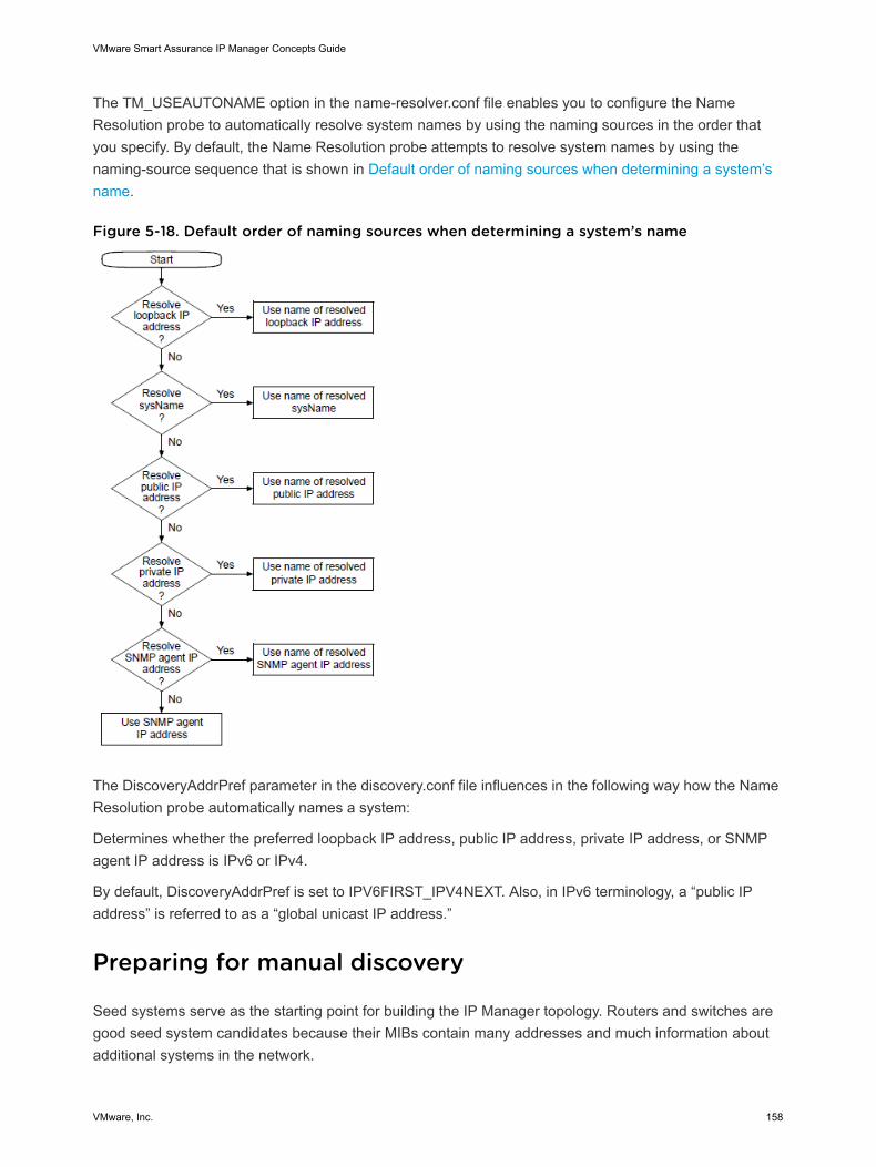
The TM_USEAUTONAME option in the name-resolver.conf file enables you to configure the NameResolution probe to automatically resolve system names by using the naming sources in the order thatyou specify. By default, the Name Resolution probe attempts to resolve system names by using thenaming-source sequence that is shown in Default order of naming sources when determining a system’sname.
Figure 5-18. Default order of naming sources when determining a system’s name
The DiscoveryAddrPref parameter in the discovery.conf file influences in the following way how the NameResolution probe automatically names a system:
Determines whether the preferred loopback IP address, public IP address, private IP address, or SNMPagent IP address is IPv6 or IPv4.
By default, DiscoveryAddrPref is set to IPV6FIRST_IPV4NEXT. Also, in IPv6 terminology, a “public IPaddress” is referred to as a “global unicast IP address.”
Preparing for manual discovery
Seed systems serve as the starting point for building the IP Manager topology. Routers and switches aregood seed system candidates because their MIBs contain many addresses and much information aboutadditional systems in the network.
VMware Smart Assurance IP Manager Concepts Guide
VMware, Inc. 158
By using manual discovery without autodiscovery, the IP Manager will discover just the seed systems.The seed systems are presented to the IP Manager as entries in a seed file, rather than being presentedindividually by using the Add Agent command. A comprehensive seed file can only be created if thenetwork topology information is complete and accessible. The VMware Smart Assurance IP ManagerUser Guide provides information on the Add Agent command.
Note The Federal Information Processing Standard (FIPS) Publication 140-2 is a U.S. governmentcomputer security standard governing cryptographic modules and is required for any software purchasedby the US government and US military. FIPS 140 mode allows you to use only SNMPv1, SNMPv2c, andSNMPv3 except MD5 and DES authentication protocols. If you run SNMPv1 or SNMPv2c, then FIPS 140mode has no impact. If you are using encryption, then you must use a certified encryption library and onlycertain encryption routines. When you discover an SNMPv3 device, you need to select the option “V3” inthe “Add Agent” window. The “Authentication Protocol” option lists only SHA and not MD5 and the“Privacy Protocol” option lists only AES and not DES. This is because MD5 and DES are not supported inFIPS 140 mode. When you discover SNMPv3 devices with MD5 and DES protocol as seed, the devicesgo to the Pending List and display as “Invalid” or “Unsupported SNMP V3 protocol”.
“Support for FIPS 140-2 in IP 9.0” section in the VMware Smart Assurance Installation Guide for SAM, IP,ESM, MPLS, and NPM Managers and the VMware Smart Assurance IP Manager Release Notes providemore information on the FIPS 140 mode implementation.
In situations where the network topology information is incomplete, unavailable, or constantly changing,manual discovery is combined with autodiscovery. The seed file can be much smaller because the seedsystems that are specified for manual discovery also serve as a starting point for autodiscovery.Autodiscovery automatically discovers the managed network from the seed systems.
For manual discovery, or manual discovery that is combined with autodiscovery, you create a seed file byediting the BASEDIR/smarts/conf/seedfile template in the IP Manager installation area. The VMwareSmart Assurance IP Manager User Guide provides the procedure for creating seed files.
Manual discovery can be used to discover SNMPv1, v2c, or v3 systems in IPv4 or IPv6 networks.
Select autodiscovery data sources
The IP Manager probes the topology and IP address table MIBs of the seed systems to find IPv4addresses of additional systems. Those IP addresses become candidate systems for the autodiscoveryprocess.
The autodiscovery process can use three different data sources of information to discover candidatesystems:
n Topology MIB
n IP address table MIB
n ARP table MIB
VMware Smart Assurance IP Manager Concepts Guide
VMware, Inc. 159
The data sources are described in Autodiscovery data sources. By default, discovery uses thetopology and IP address table MIBs of the discovered systems (initially, of the discovered seedsystems) because these MIBs are very reliable sources for topology information.
Considerations when selecting autodiscovery data sources
Here are some things to consider when selecting which data sources are to be used for autodiscovery:
n Topology MIBs
If you disable the topology MIB data source, autodiscovery may not be able to find all the systems inthe managed network.
n IP address table MIB
By default, the IP Manager pings the addresses in networks with an 8-bit host address (254 hosts), toprevent the indiscriminate pinging of large numbers of addresses. If necessary, you can change thedefault 8-bit host address setting to a larger value by editing the MaximumHostBits parameter in thediscovery.conf file. The VMware Smart Assurance IP Manager Reference Guide describes theconfiguration parameters in the discovery.conf file and provides instructions on modifying theparameters.
Depending on your network configuration, it can take the IP Manager a long time to ping the entire listof addresses when the MaximumHostsBits is set to a large value, such as 16 bits (more than 65,000addresses). With a value of 24 bits, for example, it could take the IP Manager up to several hours toping all the available addresses.
n ARP table MIB
By default, this data source is not enabled because autodiscovery does not typically gain many IPaddresses by using the ARP table MIB. In addition, autodiscovery does not read the ARP table MIB inhosts.
Initiating manual or autodiscovery
The IP Manager provides two options for initiating a manual discovery. Both options are initiated throughthe Domain Manager Administration Console:
n Option 1: Import a seed file that lists one or more seed systems to be added to the topology. Thisoption is best for adding a set of systems.
n Option 2: Add seed systems to the topology one at a time by using the Add Agent command. Thisoption is best for adding a small number of systems.
When autodiscovery is enabled, use either option to initiate the autodiscovery process. Whenenabled and initiated, autodiscovery will occur whenever either a full discovery occurs or a system onthe Pending Devices list is successfully discovered.
Using the Add Agent command to initiate discovery
VMware Smart Assurance IP Manager Concepts Guide
VMware, Inc. 160
The Add Agent command is used to enter individual seed systems. You can specify a seed system as ahostname or as an IP address:
n For a hostname, you can specify a hostname with or without an explicit IP version suffix(:v6v4, :v4v6, :v6, or :v4).
Here is an example hostname entry that includes a v4 suffix: Core-ROUTER-1:v4.
If you do not include an explicit IP version suffix, the SM_IP_VERSIONS environment variablecontrols how the local name resolution service resolves the hostname to a corresponding IP address.By default, SM_IP_VERSIONS is set to v6v4.
n For an IP address, you can specify an IPv6 or IPv4 address.
If you specify an IPv6 address, enclose the address in square brackets; for example:[2001:0db8::0010].
Here is an example IPv6 address entry that includes a port number: [2001:0db8::0010]:200.
Be careful not to add an overlapping IP address as a seed system.
Hostname syntax, the SM_IP_VERSIONS environment variable, and overlapping IP addresses arediscussed in the VMware Smart Assurance IP Manager User Guide.
Stopping autodiscovery
You can stop the autodiscovery process from the Discovery Progress window. (If the Discovery Progresswindow is not open, select Topology > Show Discovery Progress in the Domain Manager AdministrationConsole to open the window.) In the Discovery Progress window, click Stop Auto Discovery to stopautodiscovery.
Clicking the Stop Auto Discovery button stops the finding of candidate systems for autodiscovery duringPhase 3 of the discovery process. However, any systems already in the discovery queue continue to beprocessed, and the progress of this processing appears in the Discovery Progress window.
Stopping autodiscovery also disables future autodiscovery action until autodiscovery is re-enabled. TheVMware Smart Assurance IP Manager User Guide provides information on how to re-enableautodiscovery.
Initiating postprocessing
Postprocessing uses the data collected during discovery probing to create the connectivity betweensystems. The information collected from various probes is processed to create the connections betweensystems in the topology.
Phase 4: Post-process the discovery information provides more information on postprocessing.
About discovery filters
VMware Smart Assurance IP Manager Concepts Guide
VMware, Inc. 161
The purpose of discovery filters is to control or limit which systems are added to the discovery processduring autodiscovery. Appropriate discovery filtering ensures that autodiscovery is efficient.
You use discovery filters to ensure that certain network-accessible systems that are not intended formanagement by the IP Manager are not discovered. For example, an Internet service provider (ISP)might want to discover a router and its interfaces, but not the systems that are connected to the router onthe ISP’s client side. Configuring the appropriate discovery filters will enforce this discovery restriction.
Seed systems in a seed file, or seed systems that are specified by using the Add Agent command, arenot subject to the discovery filters. Only the systems that are found by the autodiscovery’s probing of theseed systems are subject to the discovery filters.
The VMware Smart Assurance IP Manager User Guide provides information on all the tasks related to thecreation of discovery filters.
Inclusive-type filtering
Discovery filters are inclusive-type filters, which mean that an autodiscovery candidate system mustmatch an IP address of a discovery filter before it is eligible for discovery. Thus, you must create at leastone discovery filter to use autodiscovery.
To prevent specific systems from being discovered, you can use the ipExcludeList parameter in theBASEDIR/smarts/conf/discovery/discovery.conf file to create exclude-type filters. The ability to createexclude-type filters simplifies the creation of the discovery filters.
Manual accept mode and system limit
You can set a manual accept mode option for a discovery filter to redirect any discovered systems thatmatch the filter to the IP Manager’s Pending Devices list. That way, you can view the systems on thePending Devices list and then select which of them should be added to the modeled topology. Theprocedure to specify the manual accept mode option is described in the VMware Smart Assurance IPManager User Guide.
In addition, you can set a system limit option for a discovery filter to limit how many discovered systemsthat match the filter are added to the topology. The procedure to specify the system limit option isdescribed in the VMware Smart Assurance IP Manager User Guide.
IPv4 and SNMPv1/v2c support
Autodiscovery and discovery filters are applicable to the discovery of SNMPv1 or v2c systems in IPv4networks. Manual discovery and seed files are applicable to the discovery of SNMPv1, v2c, or v3 systemsin IPv4 or IPv6 networks.
Discovery filter fields
VMware Smart Assurance IP Manager Concepts Guide
VMware, Inc. 162
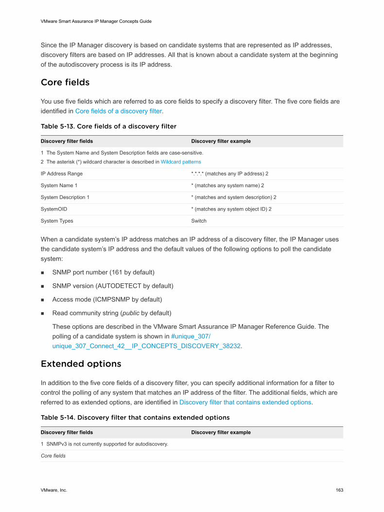
Since the IP Manager discovery is based on candidate systems that are represented as IP addresses,discovery filters are based on IP addresses. All that is known about a candidate system at the beginningof the autodiscovery process is its IP address.
Core fields
You use five fields which are referred to as core fields to specify a discovery filter. The five core fields areidentified in Core fields of a discovery filter.
Table 5-13. Core fields of a discovery filter
Discovery filter fields Discovery filter example
1 The System Name and System Description fields are case-sensitive.
2 The asterisk (*) wildcard character is described in Wildcard patterns
IP Address Range *.*.*.* (matches any IP address) 2
System Name 1 * (matches any system name) 2
System Description 1 * (matches and system description) 2
SystemOID * (matches any system object ID) 2
System Types Switch
When a candidate system’s IP address matches an IP address of a discovery filter, the IP Manager usesthe candidate system’s IP address and the default values of the following options to poll the candidatesystem:
n SNMP port number (161 by default)
n SNMP version (AUTODETECT by default)
n Access mode (ICMPSNMP by default)
n Read community string (public by default)
These options are described in the VMware Smart Assurance IP Manager Reference Guide. Thepolling of a candidate system is shown in #unique_307/unique_307_Connect_42__IP_CONCEPTS_DISCOVERY_38232.
Extended options
In addition to the five core fields of a discovery filter, you can specify additional information for a filter tocontrol the polling of any system that matches an IP address of the filter. The additional fields, which arereferred to as extended options, are identified in Discovery filter that contains extended options.
Table 5-14. Discovery filter that contains extended options
Discovery filter fields Discovery filter example
1 SNMPv3 is not currently supported for autodiscovery.
Core fields
VMware Smart Assurance IP Manager Concepts Guide
VMware, Inc. 163
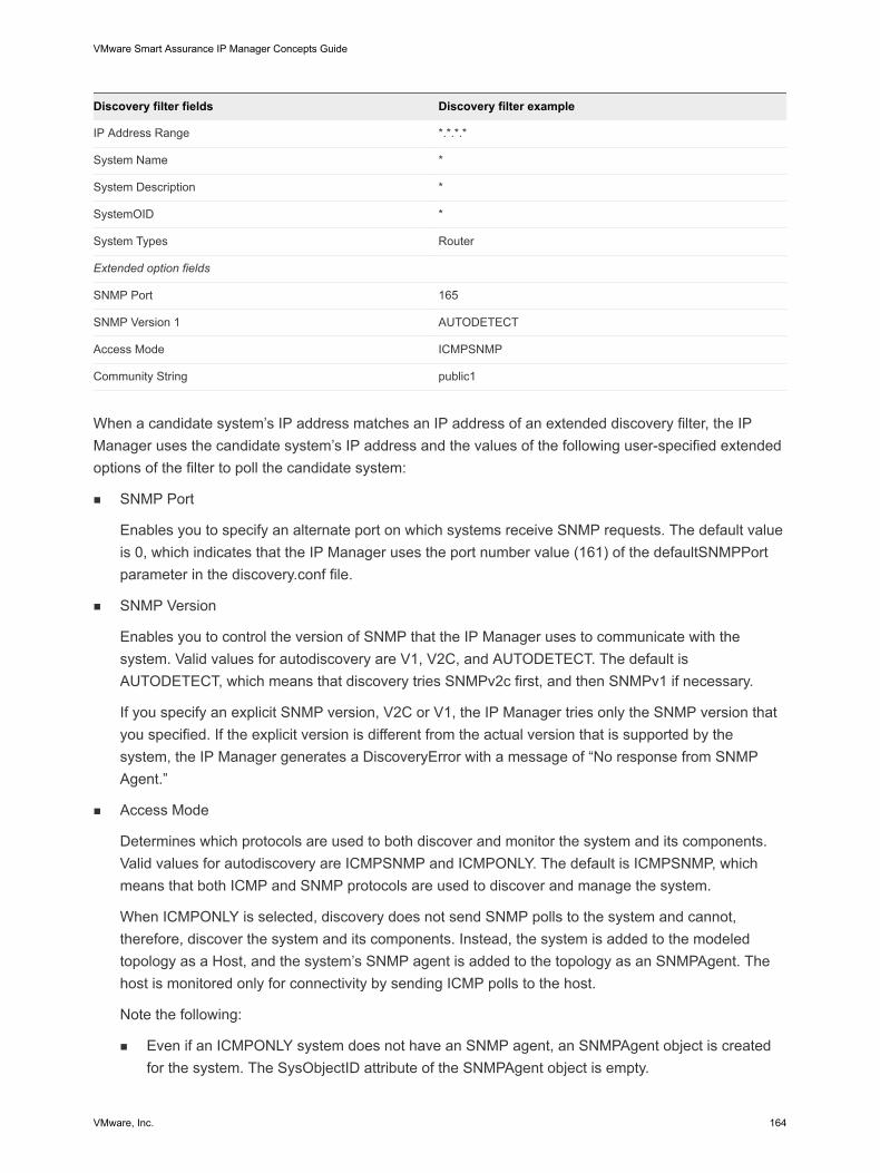
Discovery filter fields Discovery filter example
IP Address Range *.*.*.*
System Name *
System Description *
SystemOID *
System Types Router
Extended option fields
SNMP Port 165
SNMP Version 1 AUTODETECT
Access Mode ICMPSNMP
Community String public1
When a candidate system’s IP address matches an IP address of an extended discovery filter, the IPManager uses the candidate system’s IP address and the values of the following user-specified extendedoptions of the filter to poll the candidate system:
n SNMP Port
Enables you to specify an alternate port on which systems receive SNMP requests. The default valueis 0, which indicates that the IP Manager uses the port number value (161) of the defaultSNMPPortparameter in the discovery.conf file.
n SNMP Version
Enables you to control the version of SNMP that the IP Manager uses to communicate with thesystem. Valid values for autodiscovery are V1, V2C, and AUTODETECT. The default isAUTODETECT, which means that discovery tries SNMPv2c first, and then SNMPv1 if necessary.
If you specify an explicit SNMP version, V2C or V1, the IP Manager tries only the SNMP version thatyou specified. If the explicit version is different from the actual version that is supported by thesystem, the IP Manager generates a DiscoveryError with a message of “No response from SNMPAgent.”
n Access Mode
Determines which protocols are used to both discover and monitor the system and its components.Valid values for autodiscovery are ICMPSNMP and ICMPONLY. The default is ICMPSNMP, whichmeans that both ICMP and SNMP protocols are used to discover and manage the system.
When ICMPONLY is selected, discovery does not send SNMP polls to the system and cannot,therefore, discover the system and its components. Instead, the system is added to the modeledtopology as a Host, and the system’s SNMP agent is added to the topology as an SNMPAgent. Thehost is monitored only for connectivity by sending ICMP polls to the host.
Note the following:
n Even if an ICMPONLY system does not have an SNMP agent, an SNMPAgent object is createdfor the system. The SysObjectID attribute of the SNMPAgent object is empty.
VMware Smart Assurance IP Manager Concepts Guide
VMware, Inc. 164
n When an ICMPONLY system has multiple IP (v4 or v6) addresses that resolve to the same name,all IP addresses are retained. You must manually delete any IP address that no longer belongs tothe ICMPONLY system.
n An additional Access Mode option, SNMPONLY, is available to a system that is imported from aseed file, or is added to the topology by using the Add Agent command.
n Community String
Enables you to specify one or more read community strings that should be used to contact systemsthat match this filter. If no community strings are specified, autodiscovery uses the default readcommunity string. Read community strings provides information about default community strings.
Discovery filter considerations
Discovery filters are inclusive-type filters, which mean that if you do not create any filters, no candidatesystems are accepted. A system is accepted only if it matches a filter.
Consider the following points before creating discovery filters:
n When creating a filter, you must specify a value for each of its five core fields. The procedure forcreating a discovery filter is given in the VMware Smart Assurance IP Manager User Guide.
n You can create multiple filters and arrange them in a high-to-low priority. A candidate system iscompared against the highest priority filter first.
n A candidate system is subjected to two levels of filter matching, as described in Discovery filtermatching.
n When a candidate system matches all five core fields of a filter and passes any additionalautodiscovery safeguards, the system bypasses any lower priority discovery filters and becomes anobject in the topology.
n To exclude a specific candidate system, specify the system in the ipExcludeList in the discovery.conffile.
n Seed systems, as listed in a seed file or entered through the Add Agent command, are not subject tothe discovery filters.
For systems that match a discovery filter and are added to the topology, they too are probed for the IPaddresses of their neighboring systems. The autodiscovery cycle continues until no more new IPaddresses match the discovery filters.
Discovery filter matching
A candidate system is subjected to two levels of filter matching:
n First-level filter matching
Matching of IP address in the first core field of a filter, to determine whether the system is eligible fordiscovery.
VMware Smart Assurance IP Manager Concepts Guide
VMware, Inc. 165
n Second-level filter matching
Matching of other criteria in the remaining four core fields of a filter after the candidate system passesICMP and SNMP polling, to determine whether the system should be added to the modeled topology.
First-level filter matching
If a candidate system does not match the IP address of any discovery filter, the IP Manager discards thesystem.
For a candidate system that matches the IP address of a discovery filter, the IP Manager uses the SNMPport, SNMP version, access mode, and read community string values that are associated with the filter topoll the candidate system. For a non-extended filter, the polling values are identified in Core fields. For anextended filter, the polling values are identified in Extended options.
If the polling of the candidate system fails, the IP Manager either discards the system or places thesystem on the Pending Devices list. If the ICMP polling fails after the allotted number of ICMP retries, theIP Manager discards the candidate system. If the SNMP polling fails after the allotted number of SNMPretries, the IP Manager responds in one of two ways, depending on the value of theShowPendingNONSNMP parameter in the discovery.conf file:
n If ShowPendingNONSNMP is FALSE (default), the IP Manager discards the candidate system.
n If ShowPendingNONSNMP is TRUE, the IP Manager places the candidate system on the PendingDevices list.
The ShowPendingNONSNMP parameter is described in the VMware Smart Assurance IP ManagerReference Guide.
Second-level filter matching
If the polling of the candidate system is successful, the IP Manager reads the SNMP response to learnthe system name (sysName), system description (sysDescr), system OID (sysObjectID), and othersystem-related information of the candidate system.
The IP Manager then performs the following tasks to determine whether the candidate system matchesthe filter:
n Compares the retrieved system description against the System Description field in the filter.
n Compares the retrieved system OID against the SystemOID field in the filter.
n Maps the retrieved system OID to an OID in the oid2type files to identify the system’s type, and thencompares that type against the “System Types” field in the filter.
n Passes the candidate system’s IP address to the local name resolution service to resolve the addressto a name, and then compares that name against the “System Name” field in the filter.
The filter matching is shown in Phase 2: Determine the destination of the candidate system.
VMware Smart Assurance IP Manager Concepts Guide
VMware, Inc. 166
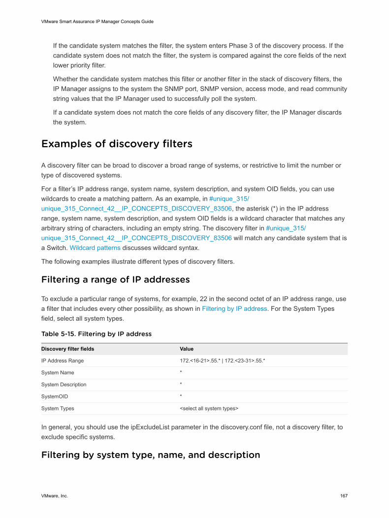
If the candidate system matches the filter, the system enters Phase 3 of the discovery process. If thecandidate system does not match the filter, the system is compared against the core fields of the nextlower priority filter.
Whether the candidate system matches this filter or another filter in the stack of discovery filters, theIP Manager assigns to the system the SNMP port, SNMP version, access mode, and read communitystring values that the IP Manager used to successfully poll the system.
If a candidate system does not match the core fields of any discovery filter, the IP Manager discardsthe system.
Examples of discovery filters
A discovery filter can be broad to discover a broad range of systems, or restrictive to limit the number ortype of discovered systems.
For a filter’s IP address range, system name, system description, and system OID fields, you can usewildcards to create a matching pattern. As an example, in #unique_315/unique_315_Connect_42__IP_CONCEPTS_DISCOVERY_83506, the asterisk (*) in the IP addressrange, system name, system description, and system OID fields is a wildcard character that matches anyarbitrary string of characters, including an empty string. The discovery filter in #unique_315/unique_315_Connect_42__IP_CONCEPTS_DISCOVERY_83506 will match any candidate system that isa Switch. Wildcard patterns discusses wildcard syntax.
The following examples illustrate different types of discovery filters.
Filtering a range of IP addresses
To exclude a particular range of systems, for example, 22 in the second octet of an IP address range, usea filter that includes every other possibility, as shown in Filtering by IP address. For the System Typesfield, select all system types.
Table 5-15. Filtering by IP address
Discovery filter fields Value
IP Address Range 172.<16-21>.55.* | 172.<23-31>.55.*
System Name *
System Description *
SystemOID *
System Types <select all system types>
In general, you should use the ipExcludeList parameter in the discovery.conf file, not a discovery filter, toexclude specific systems.
Filtering by system type, name, and description
VMware Smart Assurance IP Manager Concepts Guide
VMware, Inc. 167
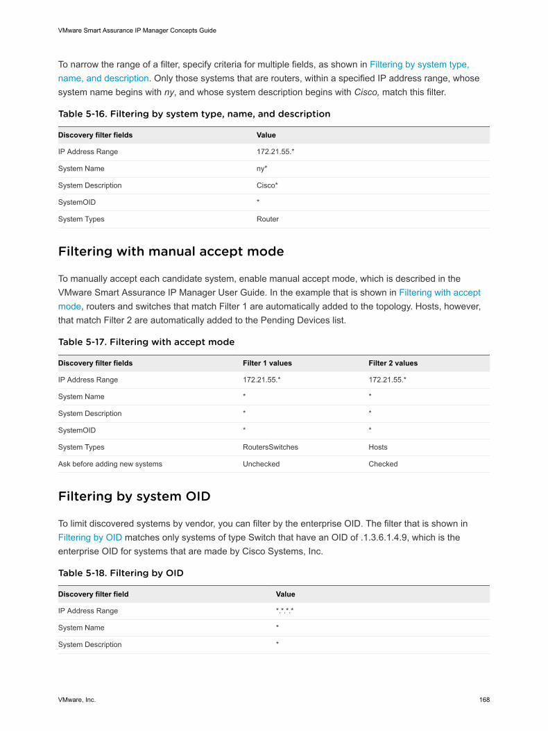
To narrow the range of a filter, specify criteria for multiple fields, as shown in Filtering by system type,name, and description. Only those systems that are routers, within a specified IP address range, whosesystem name begins with ny, and whose system description begins with Cisco, match this filter.
Table 5-16. Filtering by system type, name, and description
Discovery filter fields Value
IP Address Range 172.21.55.*
System Name ny*
System Description Cisco*
SystemOID *
System Types Router
Filtering with manual accept mode
To manually accept each candidate system, enable manual accept mode, which is described in theVMware Smart Assurance IP Manager User Guide. In the example that is shown in Filtering with acceptmode, routers and switches that match Filter 1 are automatically added to the topology. Hosts, however,that match Filter 2 are automatically added to the Pending Devices list.
Table 5-17. Filtering with accept mode
Discovery filter fields Filter 1 values Filter 2 values
IP Address Range 172.21.55.* 172.21.55.*
System Name * *
System Description * *
SystemOID * *
System Types RoutersSwitches Hosts
Ask before adding new systems Unchecked Checked
Filtering by system OID
To limit discovered systems by vendor, you can filter by the enterprise OID. The filter that is shown inFiltering by OID matches only systems of type Switch that have an OID of .1.3.6.1.4.9, which is theenterprise OID for systems that are made by Cisco Systems, Inc.
Table 5-18. Filtering by OID
Discovery filter field Value
IP Address Range *.*.*.*
System Name *
System Description *
VMware Smart Assurance IP Manager Concepts Guide
VMware, Inc. 168
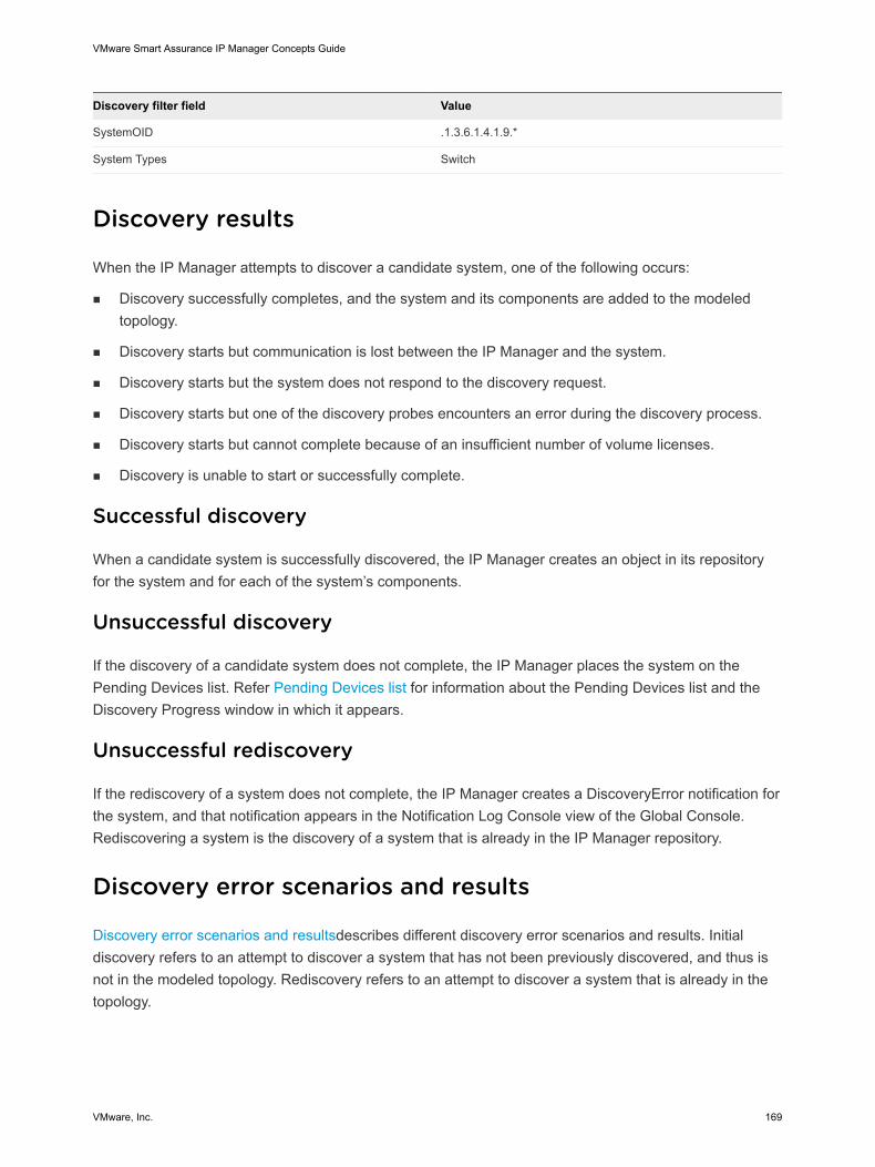
Discovery filter field Value
SystemOID .1.3.6.1.4.1.9.*
System Types Switch
Discovery results
When the IP Manager attempts to discover a candidate system, one of the following occurs:
n Discovery successfully completes, and the system and its components are added to the modeledtopology.
n Discovery starts but communication is lost between the IP Manager and the system.
n Discovery starts but the system does not respond to the discovery request.
n Discovery starts but one of the discovery probes encounters an error during the discovery process.
n Discovery starts but cannot complete because of an insufficient number of volume licenses.
n Discovery is unable to start or successfully complete.
Successful discovery
When a candidate system is successfully discovered, the IP Manager creates an object in its repositoryfor the system and for each of the system’s components.
Unsuccessful discovery
If the discovery of a candidate system does not complete, the IP Manager places the system on thePending Devices list. Refer Pending Devices list for information about the Pending Devices list and theDiscovery Progress window in which it appears.
Unsuccessful rediscovery
If the rediscovery of a system does not complete, the IP Manager creates a DiscoveryError notification forthe system, and that notification appears in the Notification Log Console view of the Global Console.Rediscovering a system is the discovery of a system that is already in the IP Manager repository.
Discovery error scenarios and results
Discovery error scenarios and resultsdescribes different discovery error scenarios and results. Initialdiscovery refers to an attempt to discover a system that has not been previously discovered, and thus isnot in the modeled topology. Rediscovery refers to an attempt to discover a system that is already in thetopology.
VMware Smart Assurance IP Manager Concepts Guide
VMware, Inc. 169
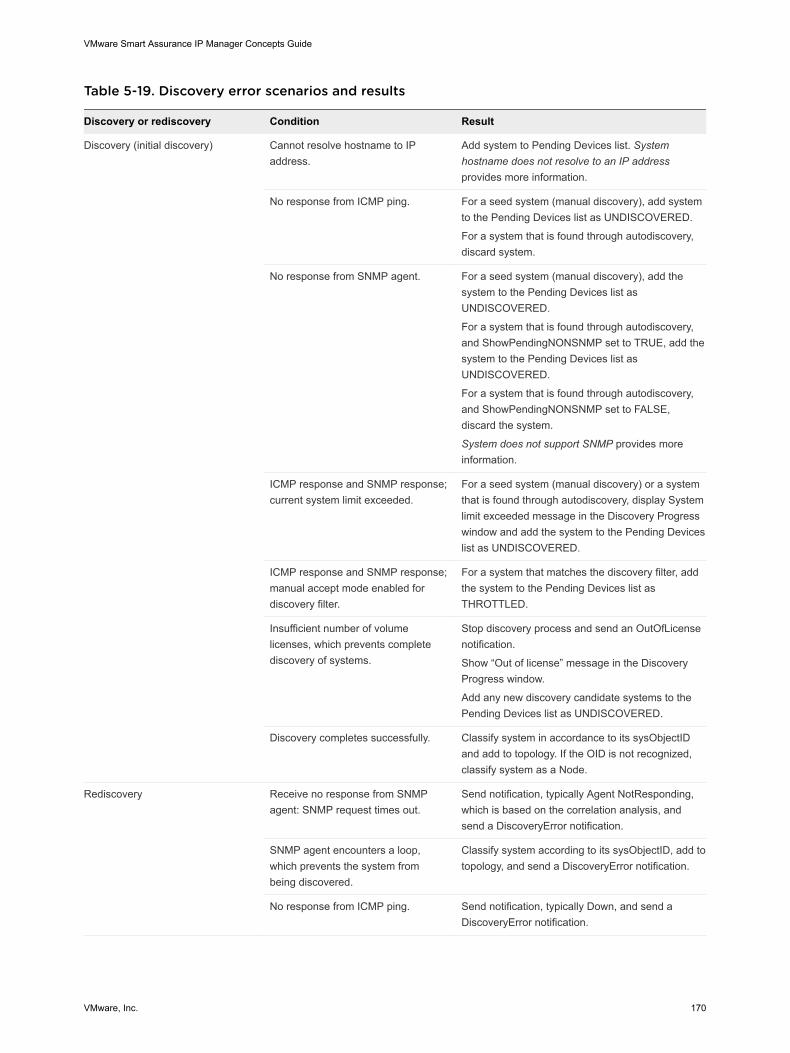
Table 5-19. Discovery error scenarios and results
Discovery or rediscovery Condition Result
Discovery (initial discovery) Cannot resolve hostname to IPaddress.
Add system to Pending Devices list. Systemhostname does not resolve to an IP addressprovides more information.
No response from ICMP ping. For a seed system (manual discovery), add systemto the Pending Devices list as UNDISCOVERED.
For a system that is found through autodiscovery,discard system.
No response from SNMP agent. For a seed system (manual discovery), add thesystem to the Pending Devices list asUNDISCOVERED.
For a system that is found through autodiscovery,and ShowPendingNONSNMP set to TRUE, add thesystem to the Pending Devices list asUNDISCOVERED.
For a system that is found through autodiscovery,and ShowPendingNONSNMP set to FALSE,discard the system.
System does not support SNMP provides moreinformation.
ICMP response and SNMP response;current system limit exceeded.
For a seed system (manual discovery) or a systemthat is found through autodiscovery, display Systemlimit exceeded message in the Discovery Progresswindow and add the system to the Pending Deviceslist as UNDISCOVERED.
ICMP response and SNMP response;manual accept mode enabled fordiscovery filter.
For a system that matches the discovery filter, addthe system to the Pending Devices list asTHROTTLED.
Insufficient number of volumelicenses, which prevents completediscovery of systems.
Stop discovery process and send an OutOfLicensenotification.
Show “Out of license” message in the DiscoveryProgress window.
Add any new discovery candidate systems to thePending Devices list as UNDISCOVERED.
Discovery completes successfully. Classify system in accordance to its sysObjectIDand add to topology. If the OID is not recognized,classify system as a Node.
Rediscovery Receive no response from SNMPagent: SNMP request times out.
Send notification, typically Agent NotResponding,which is based on the correlation analysis, andsend a DiscoveryError notification.
SNMP agent encounters a loop,which prevents the system frombeing discovered.
Classify system according to its sysObjectID, add totopology, and send a DiscoveryError notification.
No response from ICMP ping. Send notification, typically Down, and send aDiscoveryError notification.
VMware Smart Assurance IP Manager Concepts Guide
VMware, Inc. 170
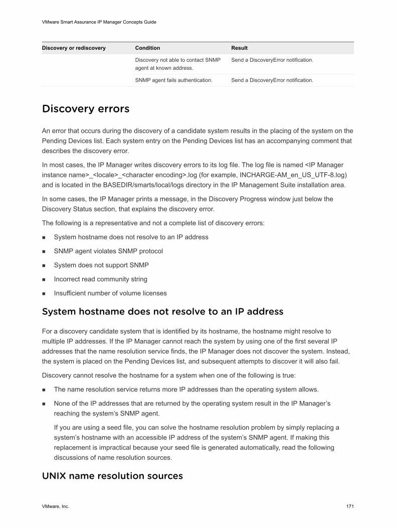
Discovery or rediscovery Condition Result
Discovery not able to contact SNMPagent at known address.
Send a DiscoveryError notification.
SNMP agent fails authentication. Send a DiscoveryError notification.
Discovery errors
An error that occurs during the discovery of a candidate system results in the placing of the system on thePending Devices list. Each system entry on the Pending Devices list has an accompanying comment thatdescribes the discovery error.
In most cases, the IP Manager writes discovery errors to its log file. The log file is named <IP Managerinstance name>_<locale>_<character encoding>.log (for example, INCHARGE-AM_en_US_UTF-8.log)and is located in the BASEDIR/smarts/local/logs directory in the IP Management Suite installation area.
In some cases, the IP Manager prints a message, in the Discovery Progress window just below theDiscovery Status section, that explains the discovery error.
The following is a representative and not a complete list of discovery errors:
n System hostname does not resolve to an IP address
n SNMP agent violates SNMP protocol
n System does not support SNMP
n Incorrect read community string
n Insufficient number of volume licenses
System hostname does not resolve to an IP address
For a discovery candidate system that is identified by its hostname, the hostname might resolve tomultiple IP addresses. If the IP Manager cannot reach the system by using one of the first several IPaddresses that the name resolution service finds, the IP Manager does not discover the system. Instead,the system is placed on the Pending Devices list, and subsequent attempts to discover it will also fail.
Discovery cannot resolve the hostname for a system when one of the following is true:
n The name resolution service returns more IP addresses than the operating system allows.
n None of the IP addresses that are returned by the operating system result in the IP Manager’sreaching the system’s SNMP agent.
If you are using a seed file, you can solve the hostname resolution problem by simply replacing asystem’s hostname with an accessible IP address of the system’s SNMP agent. If making thisreplacement is impractical because your seed file is generated automatically, read the followingdiscussions of name resolution sources.
UNIX name resolution sources
VMware Smart Assurance IP Manager Concepts Guide
VMware, Inc. 171
All supported UNIX systems return up to 35 addresses for a given name. To avoid the name resolutionproblem, you must configure your system so that at least one usable IP address is among the 35addresses that are returned.
UNIX systems translate names by using one of three sources: DNS, NIS or NIS+, or a hosts file. Thesources that are supported on a given system are specified by a host configuration file.
Note The IP Manager relies on the host operating system for name resolution. If a system is notconfigured for DNS, then there is no way to make the IP Manager use DNS other than making the systemthat the domain is running on use DNS.
The most controllable source is the hosts file, /etc/hosts. All UNIX implementations that VMwareCorporation personnel have tested will return up to the first 35 translations in order of appearance in thefile.
DNS translations are more difficult to control. First, the translations are often updated automatically.Second, the translations are sorted automatically, based on both internally defined and externallyspecified criteria.
VMware Corporation personnel have not been able to determine with certainty how translations that aremade through NIS or NIS+ are ordered.
SNMP agent violates SNMP protocol
The IP Manager implementation of the SNMP protocol is strict in that the implementation only sends orreceives SNMP messages that conform to the SNMP standard. Unfortunately, not all SNMPimplementations are as strict. The result is that the IP Manager might receive non-conforming SNMPmessages. In some cases, the IP Manager can successfully interpret and handle non-conformingmessages.
One such case is when an SNMP agent returns the values of an SNMP request in the wrong order. Forexample, the IP Manager requests the values for var1, var2, and var3, and the SNMP agent returns var1,var3, and var2.
The IP Manager writes a message to its log file:
SWFE-W-Agent violates lexicographic ordering in response to GET_NEXT: Agent:172.16.1.94, First OID:
.1.3.6.1.2.1.17.4.3.1.2.0.48.171.12.15.223
Although this problem does not hinder discovery, you might want to contact the system vendor to see if afix is available for the vendor’s implementation of the SNMP protocol.
By default, the IP Manager is configured to accept additional non-conforming SNMP messages because,in the BASEDIR/smarts/local/conf/runcmd_env.sh file, the value of the SM_SNMP_BUG_COMPATIBLEenvironment variable is set to TRUE. The VMware Smart Assurance System Administration Guideprovides information about environment variables.
System does not support SNMP
VMware Smart Assurance IP Manager Concepts Guide
VMware, Inc. 172
Certain systems, such as desktop computers or printers, do not usually support SNMP. The discoveryprocess assumes that a system supports SNMP. If a system does not support SNMP, the system is eithernot discovered or is placed on the Pending Devices list with a description that the SNMP request failed.
By default, systems that are found by autodiscovery and that do not support SNMP are removed from thediscovery queue. Systems that are imported from a seed file, or added through the Add Agent command,that do not support SNMP are always added to the Pending Devices list.
If you want to include autodiscovered, non-SNMP systems in the modeled topology, set the value of theShowPendingNONSNMP parameter to TRUE in the discovery.conf file.
When the value of ShowPendingNONSNMP is set to TRUE, candidate systems that do not supportSNMP are placed on the Pending Devices list. Managing systems on the Pending Devices list providesinformation about managing systems on the Pending Devices list.
When autodiscovery is enabled, setting ShowPendingNONSNMP to TRUE can result in a large numberof non-SNMP systems in the Pending Devices list.
Incorrect read community string
For errors that concern an incorrect read community string, you should examine the read communitystring and correct the string if necessary. In the Notification Log Console, you can determine whichcommunity string is being used by double-clicking the notification and viewing the Details tab in theNotification Properties dialog box:
For manual discovery, a read community string can be specified in the seed file or in the Add Agent dialogbox for each seed system, or one or more read community strings can be specified in the Topology tab ofthe Domain Manager Administration Console. “Adding and removing read community strings” onpage 152 provides information about how to change community strings.
For autodiscovery, one or more read community strings can be specified in a discovery filter or in theTopology tab of the Domain Manager Administration Console.
For Cisco devices, do not configure the community string with a “@” character.
After correcting the read community string, add the system to the topology with the Add Agent command.You do not have to restart autodiscovery or re-import the entire seed file just to discover this one system.
Insufficient number of volume licenses
A license file for the IP Management Suite may contain three types of licensing:
n Application licensing
n Feature licensing
n Volume licensing
Volume licensing requires a license for each discovered system.
VMware Smart Assurance IP Manager Concepts Guide
VMware, Inc. 173
Each IP Manager in the IP Manager deployment will retrieve blocks of volume licenses from thelicense server as needed when discovering systems. If an IP Manager discovers more systems thanit is licensed to discover, it will generate the OutOfLicense notification to indicate that no more volumelicenses are available and that no additional systems will be discovered.
When the OutOfLicense is notified, the IP Manager will complete the discovery of any system and itscomponents in the midst of being discovered, which includes all virtual routers that are configured fora router or a switch that implements virtual routers. When a router or switch that is implementingvirtual routers is discovered, the chassis-based router/switch is counted as a system, and each virtualrouter is counted as a system. Any new discovery candidate systems are added to the PendingDevices list in the UNDISCOVERED state, and the message “Out of license” appears below theDiscovery Status section of the Discovery Progress window.
If you receive an OutOfLicense notification, request for a new license file that has a greater number ofvolume licenses. The VMware Smart Assurance Installation Guide for SAM, IP, ESM, MPLS, andNPM Managers provides the procedure to install a license file and the VMware Smart AssuranceSystem Administration Guide provides more information about license management.
DiscoveryError notifications
Discovery errors are generated for systems that support SNMP. When an error is encountered during therediscovery of such a system, the IP Manager notifies a DiscoveryError. If the AccessMode for a systemis ICMPONLY and the system is not reachable by ICMP during discovery, the IP Manager does not notifya DiscoveryError.
To obtain more information about a DiscoveryError notification, attach the Global Console to the GlobalManager and double-click the notification in the Notification Log Console view to open the NotificationProperties dialog box. Select the Details tab to see the DiscoveryErrorInfo attribute. A Details tab appearsfor the IP Manager that notified the event.
The following is a list of errors that result in a DiscoveryError notification:
n SNMP request times out
n SNMP agent loops
n System Down
n Qualified access address not found
n System previously discovered fails authentication
n Explanation modes differ
SNMP request times out
A common error is that an SNMP request times out before it completes. There are a number of reasonswhy this error might occur:
n The system might be busy and therefore drops SNMP packets.
VMware Smart Assurance IP Manager Concepts Guide
VMware, Inc. 174
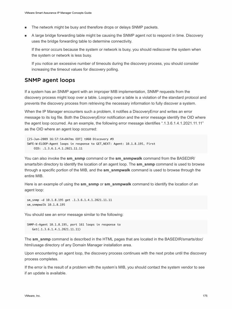
n The network might be busy and therefore drops or delays SNMP packets.
n A large bridge forwarding table might be causing the SNMP agent not to respond in time. Discoveryuses the bridge forwarding table to determine connectivity.
If the error occurs because the system or network is busy, you should rediscover the system whenthe system or network is less busy.
If you notice an excessive number of timeouts during the discovery process, you should considerincreasing the timeout values for discovery polling.
SNMP agent loops
If a system has an SNMP agent with an improper MIB implementation, SNMP requests from thediscovery process might loop over a table. Looping over a table is a violation of the standard protocol andprevents the discovery process from retrieving the necessary information to fully discover a system.
When the IP Manager encounters such a problem, it notifies a DiscoveryError and writes an errormessage to its log file. Both the DiscoveryError notification and the error message identify the OID wherethe agent loop occurred. As an example, the following error message identifies “.1.3.6.1.4.1.2021.11.11”as the OID where an agent loop occurred:
[25-Jun-2009 16:57:54+047ms EDT] t@60 Discovery #9
SWFE-W-ELOOP-Agent loops in response to GET_NEXT: Agent: 10.1.8.195, First
OID: .1.3.6.1.4.1.2021.11.11
You can also invoke the sm_snmp command or the sm_snmpwalk command from the BASEDIR/smarts/bin directory to identify the location of an agent loop. The sm_snmp command is used to browsethrough a specific portion of the MIB, and the sm_snmpwalk command is used to browse through theentire MIB.
Here is an example of using the sm_snmp or sm_snmpwalk command to identify the location of anagent loop:
sm_snmp -d 10.1.8.195 get .1.3.6.1.4.1.2021.11.11
sm_snmpwalk 10.1.8.195
You should see an error message similar to the following:
SNMP-E-Agent 10.1.8.195, port 161 loops in response to
Get(.1.3.6.1.4.1.2021.11.11)
The sm_snmp command is described in the HTML pages that are located in the BASEDIR/smarts/doc/html/usage directory of any Domain Manager installation area.
Upon encountering an agent loop, the discovery process continues with the next probe until the discoveryprocess completes.
If the error is the result of a problem with the system’s MIB, you should contact the system vendor to seeif an update is available.
VMware Smart Assurance IP Manager Concepts Guide
VMware, Inc. 175
System Down
In some cases, discovery fails because the system is Down (unreachable). When this situation occurs,the IP Manager notifies a DiscoveryError and lists the DiscoveryError as an impact of the Down problem.The value of the DiscoveryErrorInfo attribute is “No response from Ping.”
Qualified access address not found
This error occurs during rediscovery of a system when no IP address object exists in the topology for anSNMP agent, or each IP address that is associated with the SNMP agent is one of the following:
n An unmanaged IP address
n An IP address within the range of the ipExcludeList parameter in the discovery.conf file
n An IP address that is associated with an interface that is either in BACKUP or ONDEMAND mode
Because the IP Manager has no valid IP address to access the SNMP agent, it notifies aDiscoveryError.
System previously discovered fails authentication
If, during a rediscovery, the SNMP agent of a system fails authentication, the IP Manager notifies aDiscoveryError. In the Notification Log Console, you can determine the reason for the error by double-clicking the DiscoveryError notification and viewing the Details tab in the Notification Properties dialogbox. Alternatively, in the Topology Browser Console, you can determine the reason for the error bydouble-clicking the name of the failed system and viewing the Attributes tab in the system’s propertiesdialog box.
For an SNMPv1 or v2c agent, the most likely reason for this error is that the read community string for theagent has changed. Incorrect read community string provides information about errors that concern anincorrect read community string.
For an SNMPv3 agent, the most likely reason for this error is that the authentication password,authentication protocol, or username for the agent has changed. “ Seed file format provides informationabout SNMPv3 options.
Pending Devices list
The Pending Devices list, which appears in the Discovery Progress window, lists systems that are waitingto be discovered by the IP Manager. The IP Manager attempts to discover the systems on the PendingDevices list during the next pending discovery interval, or when a pending discovery is manually invoked.The VMware Smart Assurance IP Manager User Guideprovides information about the pending discoveryinterval and pending discovery.
To view the Pending Devices list, attach the Domain Manager Administration Console to the IP Managerand select Topology >Show Discovery Progress.
VMware Smart Assurance IP Manager Concepts Guide
VMware, Inc. 176
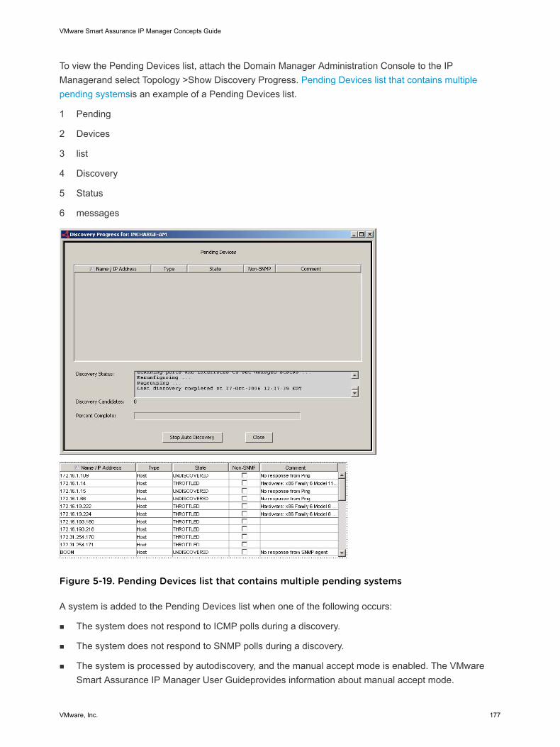
To view the Pending Devices list, attach the Domain Manager Administration Console to the IPManagerand select Topology >Show Discovery Progress. Pending Devices list that contains multiplepending systemsis an example of a Pending Devices list.
1 Pending
2 Devices
3 list
4 Discovery
5 Status
6 messages
Figure 5-19. Pending Devices list that contains multiple pending systems
A system is added to the Pending Devices list when one of the following occurs:
n The system does not respond to ICMP polls during a discovery.
n The system does not respond to SNMP polls during a discovery.
n The system is processed by autodiscovery, and the manual accept mode is enabled. The VMwareSmart Assurance IP Manager User Guideprovides information about manual accept mode.
VMware Smart Assurance IP Manager Concepts Guide
VMware, Inc. 177
n The number of discovered systems exceeds the current system limit. The VMware Smart AssuranceIP Manager User Guideprovides information about setting the current system limit.
n The number of discovered systems exceeds the number of volume licenses that are available to theIP Manager. Insufficient number of volume licenses provides information about volume licenses andthe OutOfLicense notification.
n The system does not support SNMP, which means that the system responded to ICMP polls but thediscovery process could not contact an SNMP agent for the system.
n The IP Manager receives an SNMP trap that indicates that the configuration of the system might havechanged. A system is placed on the Pending Devices list when one of the following traps is received:
n coldStart (RFC 1215 MIB)
n warmStart (RFC 1215 MIB)
n a3ComSysModuleCardInsertEvent (3COM CB9000-MIB)
n cefcFRUInserted (CISCO-ENTITY-FRU-CONTROL-MIB)
n cefcFRURemoved (CISCO-ENTITY-FRU-CONTROL-MIB)
n ciscoConfigManEvent (CISCO-CONFIG-MAN-MIB)
n sysConfigChangeTrap (CISCO-STACK-MIB)
Information provided by the Pending Devices list
The Pending Devices list contains five columns that provide the following information for each system:
n Hostname or IP address of the system that could not be discovered.
n Type, which is one of the system types
n State is either UNDISCOVERED or THROTTLED, as described in Discovery states.
n Non-SNMP is a checkbox for indicating that the system does not support SNMP.
n Comment describes why the system is on the Pending Devices list, or contains the system’sSysDescr value of the system if the current system limit has been exceeded.
Discovery states describes the discovery states and the actions you can take to resolve the situation.
VMware Smart Assurance IP Manager Concepts Guide
VMware, Inc. 178
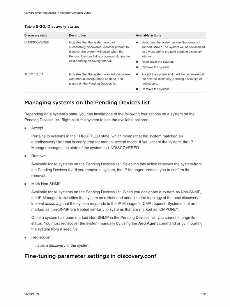
Table 5-20. Discovery states
Discovery state Description Available actions
UNDISCOVERED Indicates that the system was notsuccessfully discovered. Another attempt todiscover the system will occur when thePending Devices list is processed during thenext pending discovery interval.
n Designate the system as one that does notsupport SNMP. The system will be reclassifiedas a Host during the next pending discoveryinterval.
n Rediscover the system.
n Remove the system.
THROTTLED Indicates that the system was autodiscoveredwith manual accept mode enabled, andplaced on the Pending Devices list.
n Accept the system and it will be discovered atthe next full discovery, pending discovery, orrediscovery.
n Remove the system.
Managing systems on the Pending Devices list
Depending on a system’s state, you can invoke one of the following four actions on a system on thePending Devices list. Right-click the system to see the available actions:
n Accept
Pertains to systems in the THROTTLED state, which means that the system matched anautodiscovery filter that is configured for manual accept mode. If you accept the system, the IPManager changes the state of the system to UNDISCOVERED.
n Remove
Available for all systems on the Pending Devices list. Selecting this action removes the system fromthe Pending Devices list. If you remove a system, the IP Manager prompts you to confirm theremoval.
n Mark Non-SNMP
Available for all systems on the Pending Devices list. When you designate a system as Non-SNMP,the IP Manager reclassifies the system as a Host and adds it to the topology at the next discoveryinterval assuming that the system responds to the IP Manager’s ICMP request. Systems that aremarked as non-SNMP are treated similarly to systems that are marked as ICMPONLY.
Once a system has been marked Non-SNMP in the Pending Devices list, you cannot change itsstatus. You must rediscover the system manually by using the Add Agent command or by importingthe system from a seed file.
n Rediscover
Initiates a discovery of the system.
Fine-tuning parameter settings in discovery.conf
VMware Smart Assurance IP Manager Concepts Guide
VMware, Inc. 179
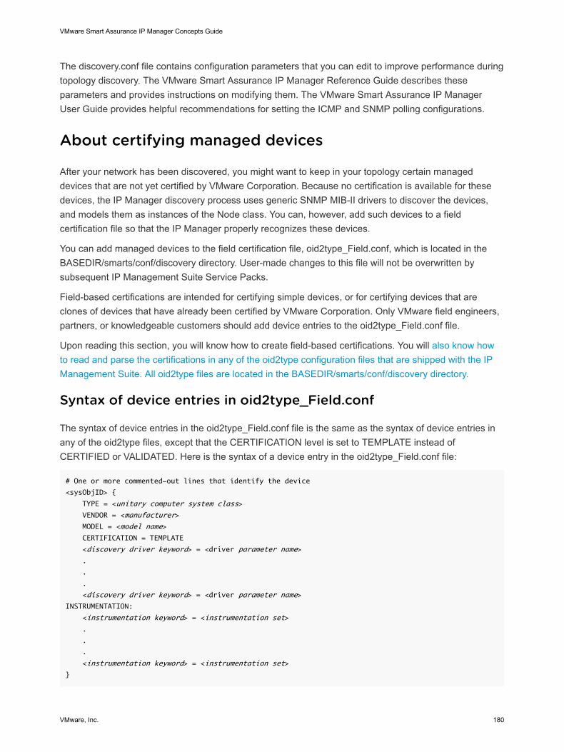
The discovery.conf file contains configuration parameters that you can edit to improve performance duringtopology discovery. The VMware Smart Assurance IP Manager Reference Guide describes theseparameters and provides instructions on modifying them. The VMware Smart Assurance IP ManagerUser Guide provides helpful recommendations for setting the ICMP and SNMP polling configurations.
About certifying managed devices
After your network has been discovered, you might want to keep in your topology certain manageddevices that are not yet certified by VMware Corporation. Because no certification is available for thesedevices, the IP Manager discovery process uses generic SNMP MIB-II drivers to discover the devices,and models them as instances of the Node class. You can, however, add such devices to a fieldcertification file so that the IP Manager properly recognizes these devices.
You can add managed devices to the field certification file, oid2type_Field.conf, which is located in theBASEDIR/smarts/conf/discovery directory. User-made changes to this file will not be overwritten bysubsequent IP Management Suite Service Packs.
Field-based certifications are intended for certifying simple devices, or for certifying devices that areclones of devices that have already been certified by VMware Corporation. Only VMware field engineers,partners, or knowledgeable customers should add device entries to the oid2type_Field.conf file.
Upon reading this section, you will know how to create field-based certifications. You will also know howto read and parse the certifications in any of the oid2type configuration files that are shipped with the IPManagement Suite. All oid2type files are located in the BASEDIR/smarts/conf/discovery directory.
Syntax of device entries in oid2type_Field.conf
The syntax of device entries in the oid2type_Field.conf file is the same as the syntax of device entries inany of the oid2type files, except that the CERTIFICATION level is set to TEMPLATE instead ofCERTIFIED or VALIDATED. Here is the syntax of a device entry in the oid2type_Field.conf file:
# One or more commented-out lines that identify the device
<sysObjID> {
TYPE = <unitary computer system class>
VENDOR = <manufacturer>
MODEL = <model name>
CERTIFICATION = TEMPLATE
<discovery driver keyword> = <driver parameter name>
.
.
.
<discovery driver keyword> = <driver parameter name>
INSTRUMENTATION:
<instrumentation keyword> = <instrumentation set>
.
.
.
<instrumentation keyword> = <instrumentation set>
}
VMware Smart Assurance IP Manager Concepts Guide
VMware, Inc. 180
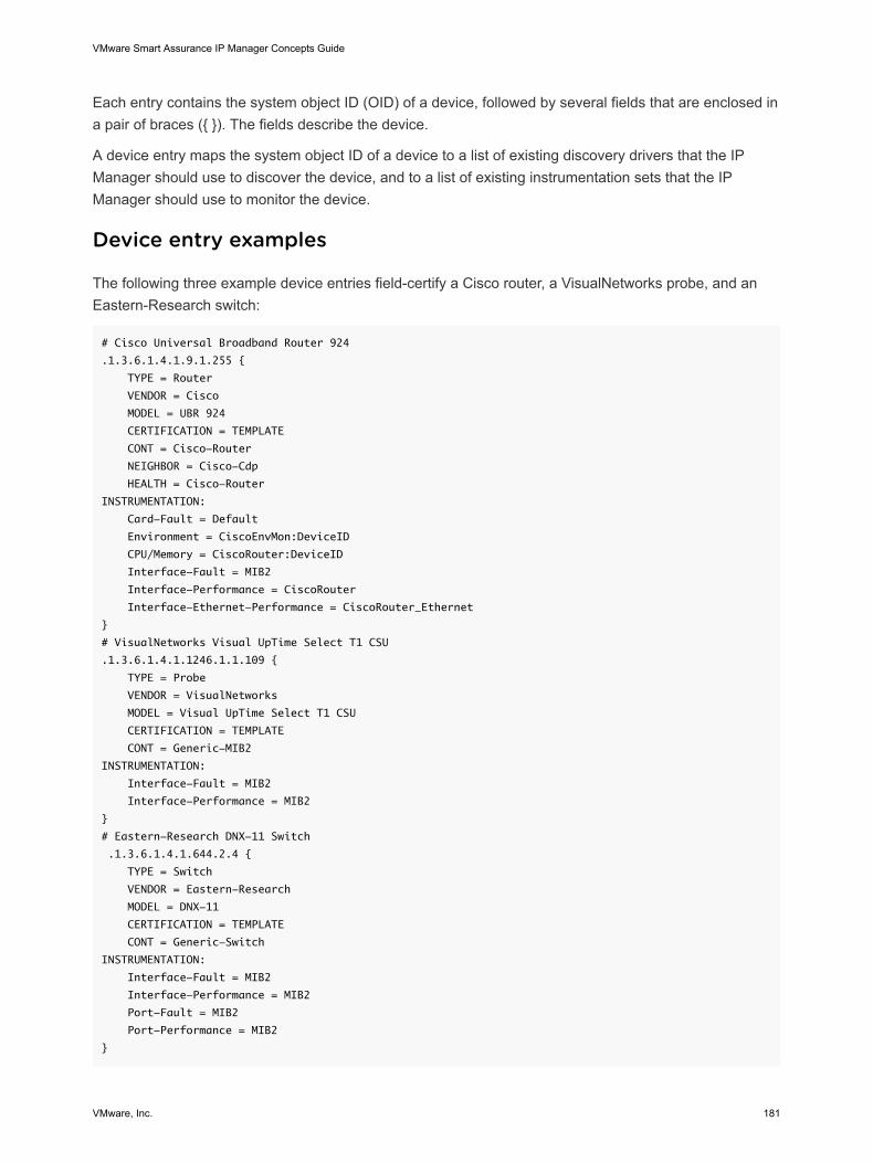
Each entry contains the system object ID (OID) of a device, followed by several fields that are enclosed ina pair of braces ({ }). The fields describe the device.
A device entry maps the system object ID of a device to a list of existing discovery drivers that the IPManager should use to discover the device, and to a list of existing instrumentation sets that the IPManager should use to monitor the device.
Device entry examples
The following three example device entries field-certify a Cisco router, a VisualNetworks probe, and anEastern-Research switch:
# Cisco Universal Broadband Router 924
.1.3.6.1.4.1.9.1.255 {
TYPE = Router
VENDOR = Cisco
MODEL = UBR 924
CERTIFICATION = TEMPLATE
CONT = Cisco-Router
NEIGHBOR = Cisco-Cdp
HEALTH = Cisco-Router
INSTRUMENTATION:
Card-Fault = Default
Environment = CiscoEnvMon:DeviceID
CPU/Memory = CiscoRouter:DeviceID
Interface-Fault = MIB2
Interface-Performance = CiscoRouter
Interface-Ethernet-Performance = CiscoRouter_Ethernet
}
# VisualNetworks Visual UpTime Select T1 CSU
.1.3.6.1.4.1.1246.1.1.109 {
TYPE = Probe
VENDOR = VisualNetworks
MODEL = Visual UpTime Select T1 CSU
CERTIFICATION = TEMPLATE
CONT = Generic-MIB2
INSTRUMENTATION:
Interface-Fault = MIB2
Interface-Performance = MIB2
}
# Eastern-Research DNX-11 Switch
.1.3.6.1.4.1.644.2.4 {
TYPE = Switch
VENDOR = Eastern-Research
MODEL = DNX-11
CERTIFICATION = TEMPLATE
CONT = Generic-Switch
INSTRUMENTATION:
Interface-Fault = MIB2
Interface-Performance = MIB2
Port-Fault = MIB2
Port-Performance = MIB2
}
VMware Smart Assurance IP Manager Concepts Guide
VMware, Inc. 181
Device entry field descriptions
Chapter 5, Discovery, in the VMware Smart Assurance IP Manager Reference Guide describes thedevice entry fields for a field-based certification.
Note the following about device entry field descriptions in oid2type_Field.conf:
n The discovery driver keywords are listed in the ic-oid2type.asl file, which is located in the BASEDIR/smarts/rules/discovery directory.
n For each discovery driver keyword in a device entry, the IP Manager searches the ic-oid2type.asl fileto find the prefix value that is needed to identify the name of the appropriate discovery driver. Thenaming format for a discovery driver is:
<prefix>-<param-name>-Driver
The driver class is either GA_Driver or GA_CompoundDriver.
n Once the appropriate discovery driver is identified, the IP Manager finds the discovery driver inthe .import files, which are located with the oid2type files in the BASEDIR/smarts/conf/discoverydirectory.
The discovery drivers that are associated with the discovery driver keywords are described in detail in“Phase 3: Probe the system added to the topology” on page 38.
The discovery drivers that are associated with the ADNR and DSCVDATA keywords work together togather MIB-II-like interface and IP data within a device’s vendor-specific MIBs. The gathered data isused to determine whether the target device is a “match” to another device.
Although a “VRRP” keyword exists to point to vendor-specific VRRP drivers, no comparable keyword,say “HSRP,” exists to point to vendor-specific HSRP drivers. Reason: HSRP is a Cisco-proprietaryprotocol that runs only on Cisco devices. The HSRP driver, named Cisco-HSRPGroup-Driver, isdefined in the DISCOVERY_CISCO.import file.
Many of the discovery driver and instrumentation keywords have MIB-II counterparts that can beuseful in field certifications. Here are some examples:
n CONT = Generic-MIB2
n HOSTRESRCS = MIB2
n Interface-Fault = MIB2
n Interface-Performance = MIB2
n Interface-Ethernet-Performance = MIB2
n Port-Fault = MIB2
n Port-Performance = MIB2
n Port-Ethernet-Performance = MIB2
For a device entry that specifies MIB-II discovery and instrumentation, the IP Manager will usegeneric SNMP MIB-II drivers and instrumentation to discover and monitor the device.
VMware Smart Assurance IP Manager Concepts Guide
VMware, Inc. 182
Device entries for oid2type_Field.conf
Field certification is useful when a new device uses the same discovery drivers and instrumentation as anexisting VMware-certified device. For example, when the new device, say a Cisco 2503, is a variant of anVMware-certified device, say Cisco 2502.
You accomplish a field certification by fully or partially reusing the discovery driver parameters andinstrumentation parameters for an existing VMware-tested certification. Typically, you use a trial-and-errorapproach to find the most suitable combination of driver and instrumentation parameters for the devicethat you want to certify.
Except for very simple devices, you should consult with VMware Customer Support when creating deviceentries in the oid2type_Field.conf file.
“Adding device entries to oid2type_Field.conf” section in Chapter 3, Discovery, in the VMware SmartAssurance IP Manager User Guide, provides information on how to add device entries to theoid2type_Field.conf file.
Discovery driver parameters
For field certification of a new device, you specify the discovery driver parameters that will enable the IPManager to properly represent the device in its modeled topology.
If, for example, you want to discover a new Cisco router, look in the oid2type.conf or oid2type_Cisco.conffile for a Cisco router that is a variant of the new Cisco router, and then use the discovery drivers for thatrouter to discover the new router.
Also, here is some information about discovery drivers that you might find helpful when specifyingdiscovery drivers for a new device:
n A discovery driver is either a GA_Driver or a GA_CompoundDriver and is defined in a .import file. AGA_CompoundDriver lists a series of GA_CompoundDrivers or GA_Drivers or both that the IPManager will run in the order that the drivers are specified. A GA_Driver specifies a ruleset andpossibly a front end.
n At startup, the IP Manager loads into memory all of the drivers in the .import files and all of thecertifications in the oid2type files. For this reason, a GA_CompoundDriver can refer to a driver that islocated in a different .import file.
Instrumentation parameters
For field certification of a new device, you also specify the instrumentation parameters that will enable theIP Manager to correctly monitor the device for connectivity and performance analysis.
If, for example, you want to monitor the CPU on a new Cisco router, look in the oid2type.conf oroid2type_Cisco.conf file for a Cisco router that is a variant of the new Cisco router, and then use the CPU/memory instrumentation for that router to monitor the CPU on the new router.
Submit certification request to VMware
VMware Smart Assurance IP Manager Concepts Guide
VMware, Inc. 183
Ultimately, for a field-certified device, you should submit a device certification request to VMwareCorporation so that the device will be certified in future releases of the IP Management Suite. VMwareCorporation will use specialized tools to make the certification more accurate, and will apply standardquality assurance testing to the certification.
To submit a device certification request, go to the VMware online support website at support.vmware.comand select Support. On the Support page, you will see several options, including one for making a servicerequest.
To open a service request, you must have a valid support agreement. Contact your VMware salesrepresentative for details about obtaining a valid support agreement or with questions about your account.
Discovery hook scripts
In addition to the steps that are performed automatically during the discovery process, you can usediscovery hook scripts to specify additional steps to occur at various stages of the discovery. Forexample, you could use a postprocessing script to manage or unmanage IP objects during thepostprocessing phase of the discovery. The discovery hook scripts are written in the VMware SmartAssurance proprietary Adapter Scripting Language (ASL).
When discovery hook scripts run
The discovery hook scripts are identified in the DISCOVERY_CUSTOM.import and POST-DISCOVERY_CUSTOM.import files, which are located in the BASEDIR/smarts/conf/discovery directory inthe IP Manager installation area.
Each time the IP Manager performs a discovery cycle, it runs the main discovery drivers plus thediscovery hook scripts that are identified in the DISCOVERY_CUSTOM.import file. The discovery may bean initial discovery, a full discovery, or a pending discovery.
By default, running the discovery hook scripts has no effect on the discovery process because the scriptsare just template files, which mean that you must open the scripts with an editor and add the code thatperforms the actual processing.
How discovery hook scripts identify systems for processing
The VMware Smart Assurance IP Manager Reference Guide shows how the custom-end-system.aslscript identifies systems for processing. The discovery process automatically assigns the following valueto the AgentName variable:
Name of SNMP agent that is hosted by the system that is currently being discovered
The custom-end-system.asl script uses the value of AgentName to obtain the name of the system byinvoking the getSystem() operation on the SNMP agent object.
The custom-start-system.asl script uses the same method to identify systems for processing.
Discovery hook scripts and ICMPSNMP and ICMPONLY systems
VMware Smart Assurance IP Manager Concepts Guide
VMware, Inc. 184
If during the initial polling phase a system is assigned an ICMPSNMP access mode, the discoveryprocess calls the custom-end-system.asl script. In contrast, if during the initial polling phase a system isassigned an ICMPONLY access mode, the discovery process does not call the custom-end-system.aslscript. For an ICMPONLY system, the discovery process schedules the system for postprocessing rightafter the initial polling phase because additional probing is not applied to an ICMPONLY system.
Thus, any custom code that you add to the custom-end-system.asl script is applied to ICMPSNMPsystems but not ICMPONLY systems. If you want to customize the discovery of both ICMPSNMP andICMPONLY systems, you should add your custom code to the custom-start-post.asl script, the custom-end-post.asl script, or both.
Discovery methods describes the discovery process and identifies the topology that is discovered by theIP Manager.
“Modifying discovery hook scripts” section in Chapter 3, Discovery, in the VMware Smart Assurance IPManager User Guide, provides information on how to edit a discovery hook script to add the ASLconvenience patterns, the parsing rules, and the processing rules that perform the actual processing.
Automatic and manual discovery
Automatic discovery is scheduled under the control of an ICF-TopologyManager program that is runningin the IP Manager. The ICF-TopologyManager controls all aspects of discovery, including the schedulingof automatic discovery and the execution of manually invoked discovery requests.
After the initial discovery by an IP Manager, you can schedule automatic discovery at a regular intervaland manually invoke discovery at any time. You perform these tasks through a Domain ManagerAdministration Console that is attached to the IP Manager, or from the command line by using the dmctlutility.
Discovery methods
For both automatic and manual discovery, the following two methods of discovery are available:
n Full discovery
n Pending discovery
Manual rediscovery of individual systems is also available.
Full discovery
During the initial full discovery, the IP Manager populates its repository with the topology that isdiscovered in the managed network environment. During any subsequent full discovery, the IP Managerattempts to rediscover the topology in its repository.
VMware Smart Assurance IP Manager Concepts Guide
VMware, Inc. 185
Rediscovering the topology reveals any changes in the configuration or connectivity of the managedsystems and keeps the topology current. For example, if a card is added to a switch, the IP Managermust rediscover the switch so that it can add the new card to the topology. And if new systems have beenadded to the network and autodiscovery is enabled, the IP Manager will discover the new systems duringthe rediscovery.
Pending discovery
During a pending discovery, the IP Manager attempts to discover the systems on the Pending Deviceslist. The Pending Devices list contains the names of the systems that could not be discovered by the IPManager.
You can view the Pending Devices list at any time by selecting Topology > Show Discovery Progress fromthe Domain Manager Administration Console. Pending Devices list describes the various aspects of thePending Devices list.
Discovery considerations
Initiating a full discovery for a large topology can take a considerable amount of time, ranging from 1 hourto 2 or more hours, depending on the actual size of the topology. Keep this in mind when scheduling fulldiscovery for the IP Manager.
Also, consider scheduling automatic full discovery during off hours (5:00 in the morning, for example). TheVMware Smart Assurance IP Manager Deployment Guide recommends scheduling full discovery at leastweekly and pending discovery at least daily. Typically, the duration of a pending discovery is much shorterthan the duration of a full discovery.
Running the discovery more often will provide a more accurate network topology, but will also cost morein terms of network and system resources.
Scheduling automatic discovery
You can schedule full discovery and pending discovery intervals:
n Scheduling a full discovery interval determines how often the IP Manager attempts to rediscover theexisting systems in its repository.
n Scheduling a pending discovery interval determines how often the IP Manager attempts to discoverthe systems on the Pending Devices list.
By default, the full discovery interval is enabled and set to 1 day, and the pending discovery interval isenabled and set to 6 hours. The parameters that control scheduled discovery are located on theTopology tab page of the Domain Manager Administration Console.
The full discovery interval should not be set to less than 60 minutes, and the pending discoveryinterval should not be set to less than 5 minutes. Violating either of these restrictions will result in theprinting of an exception by the Domain Manager Administration Console. For example:
VMware Smart Assurance IP Manager Concepts Guide
VMware, Inc. 186
Apply changes failed: Invalid full discovery interval
The VMware Smart Assurance IP Manager User Guide provides information on how to configure thefull and pending discovery intervals.
Read community strings
You can specify the read community strings that are used by discovery in several different places:
n Discovery filter
n Seed file
n Add Agent command
If read community strings are specified for a discovery filter, the IP Manager uses those communitystrings when polling the systems that match the discovery filter. The VMware Smart Assurance IPManager User Guide provides information about specifying read community strings for a discoveryfilter.
If no read community string is specified in a discovery filter, or no community string is specified in theseed file or through the Add Agent command, or the specified community string is not correct, the IPManager selects a community string in the following manner:
n Tries the community strings that appear in the Read Community Strings window (Topology tab) of theDomain Manager Administration Console.
n If no community strings appear in the Read Community Strings window, reads the default readcommunity string in the discovery.conf file.
n If no read community strings are found for a system, places the system on the Pending Devices listduring an initial discovery attempt, or notifies a DiscoveryError during a rediscovery attempt.
Initial discovery and rediscovery errors are discussed in Discovery error scenarios and results.
About managing and unmanaging topology objects
The IP Manager monitors managed objects but not unmanaged objects. The IP Manager uses ICMP andSNMP, unless a different access mode is specified, to monitor a managed object for the purpose ofdetermining the object’s status and connectivity. An unmanaged object is not polled or rediscovered bythe IP Manager, but remains present in the modeled topology.
A managed object is an object whose IsManaged attribute has a value of TRUE. IsManaged is a Booleanattribute: TRUE when an object is managed, and FALSE when an object is unmanaged.
The Manage and Unmanage commands enable you to control whether an object is managed.Unmanaging a system might be useful when, for example, a switch or a card is taken offline formaintenance.
Types of objects that can be managed or unmanaged
VMware Smart Assurance IP Manager Concepts Guide
VMware, Inc. 187
You can set the management state for the following types of objects:
n Systems such as routers, switches, and hosts
n Physical packages such as cards
n Network adapters such as ports and interfaces
n Protocol endpoints such as IP interfaces and STP nodes
n Management agents such as SNMP agents
n Logical devices such as fans, processors, temperature and voltage sensors, and file systems
n Redundancy groups such as redundancy groups that represent two or more cards or two or morenetwork connections
The ability to unmanage IP interfaces enables you to develop flexible management policies. Whenyou unmanage an IP interface, the underlying physical interface continues to be managed becausethe status of the IP interface is determined by using ICMP, and the status of the physical interface isdetermined by using SNMP.
You can unmanage the IP interfaces on systems where ICMP pings are not allowed because, forexample, of a firewall. When you unmanage these IP interfaces, the IP Manager no longer polls themthrough ICMP. More important, however, is that the IP Manager still manages the underlying physicalinterfaces through SNMP.
Rules that govern manage and unmanage operations
The Manage and Unmanage commands are recursive. When you unmanage an object, all themanagement agent services and other objects that are functionally dependent on that object becomeunmanaged. For example, if you unmanage a switch, all of the ports and cards that belong to the switchare unmanaged.
The following list of rules determines whether an object can be managed or unmanaged and explains therecursive nature of the Manage and Unmanage commands:
n When you unmanage a system, a management agent service that is hosted by or is a part of thatsystem also becomes unmanaged. For example, a system, such as a router, hosts an SNMP agentservice. If you unmanage a router that hosts an SNMP agent service, the SNMP agent service is alsounmanaged.
n When you unmanage a system, any logical device that is a part of that system also becomesunmanaged. Logical devices include objects such as fans, temperature and voltage sensors,processors, and file systems. Ports and interfaces also become unmanaged. If you unmanage asystem, such as a router, the interfaces and sensors that are part of that router are not managed, norcan they be managed while the parent object is unmanaged. Likewise, if you manage a system, all ofits components are managed except those that are explicitly unmanaged.
n When you add a logical device or service to an unmanaged system, that logical device or serviceautomatically becomes unmanaged. For example, if an interface is added to an unmanaged host, thenew interface is also unmanaged.
VMware Smart Assurance IP Manager Concepts Guide
VMware, Inc. 188
n When you unmanage a service, the protocol endpoint that is associated with that service becomesunmanaged.
n When you unmanage a logical device or a protocol endpoint, any other protocol endpoint that islayered over that logical device or protocol endpoint becomes unmanaged. For example, if youunmanage an interface, the subinterfaces or IP addresses that are layered over that interface arealso unmanaged.
n When you unmanage a card, the managed state of any sub-cards, network adapters that are realizedby the card, or systems that are packaged by the card remain managed. As such, monitoring andanalysis of these items continue.
Methods to control the management state of objects
You can use any of the following methods to control the management state of objects:
n Set the management state of individual objects by attaching the Global Console to the IP Managerand by using the Manage and Unmanage commands.
The VMware Smart Assurance IP Manager User Guide provides information on how to set themanagement state of an object.
n Use the discovery hook scripts that are provided with the IP Manager to set the management state forIPs, devices, interfaces, ports, and other objects.
For example, if there are groups of IP addresses that are not normally reachable by using ICMPpolling, specify the IP ranges or matching criteria in the custom-end-post.asl file to ensure that the IPManager will set the management state of these IP addresses to unmanaged. The IP Manager willnot ping IP addresses that are unmanaged.
The VMware Smart Assurance IP Manager User Guide provides information on how to use discoveryhook scripts.
n Use the Interface Management Policy that is provided with the IP Manager to set the managementstate for interfaces.
The Interface Management Policy, which is accessible through a Polling and Thresholds Console,enables you to set a system-level policy to unmanage interfaces. By default, this policy is not active.
The VMware Smart Assurance IP Manager User Guide describes the Interface Management Policyand provides instructions on changing its setting.
n Create IP tag filter groups to not only tag specific IP addresses on a discovered system, but to alsoset those IP addresses to managed or unmanaged when the system is discovered.
The VMware Smart Assurance IP Manager User Guide describes the IP tagging feature and providesinstructions on creating IP tag filter groups.
Persistent management state
VMware Smart Assurance IP Manager Concepts Guide
VMware, Inc. 189
The IP Manager retains the management state of ports, interfaces, IP addresses, and SNMP agents inthe following situations:
n After a system has been recertified
n If the name format has been changed, as described in How discovery names a system
If the DNS configuration has been changed
Incremental reconfigure
If new devices are added to the topology, a full reconfiguration happens which is time consuming. Anincremental reconfigure happens only for the devices added, and is faster.
To enable incremental reconfigure, set ThresholdOfChangedUCSForIncReconfig 10 in the tpmgr-param.conf file. The value of this flag controls the maximum number of devices for which incrementalreconfigure will run. For example, if the value is 10, incremental reconfigure will run if the number of thelast discovered device is less then 10, otherwise a bulk reconfigure will run.
By default, ThresholdOfChangedUCSForIncReconfig is set to 10 in tpmgr-param.conf. This means thatfor a discovery containing less than 10 systems, the reconfigure started and reconfigure finishedmessages will not be logged in the domain log. However, reconfigure will still take place. In order toobserve the incremental reconfigure messages, set DebugReconfigure TRUE in tpmgr-param.conf.
To make the required change in tpmgr-param.conf, type:
<BASEDIR>/IP/smarts/bin/sm_edit conf/discovery/tpmgr-param.conf
To restart the IP domain or reload tpmgr-param.conf for the change to take affect, type:
<BASEDIR>/IP/smarts/bin/sm_tpmgr -s <IP 8.1.X domain> --load-conf=tpmgr-param.conf
To verify the ThresholdOfChangedUCSForIncReconfig setting, type:
<BASEDIR>/IP/smarts/bin/dmctl -s <IP 8.1.X domain> invoke ICF_TopologyManager::ICF-TopologyManager findParameter ThresholdOfChangedUCSForIncReconfig
To make the necessary change without restarting the IP domain, type:
<BASEDIR>/IP/smarts/bin/dmctl -s <IP 8.1.X domain> invoke ICF_TopologyManager::ICF-TopologyManager insertParameter ThresholdOfChangedUCSForIncReconfig <value>
To verify the debug setting, type:
<BASEDIR>/IP/smarts/bin/dmctl -s <IP 8.1.X domain> invoke ICF_TopologyManager::ICF-TopologyManager findParameter DebugReconfigure
To make the necessary change without restarting the IP domain, type:
<BASEDIR>/IP/smarts/bin/dmctl -s <IP 8.1.X domain> invoke ICF_TopologyManager::ICF-TopologyManager insertParameter DebugReconfigure TRUE
Handling duplicate IP address errors
VMware Smart Assurance IP Manager Concepts Guide
VMware, Inc. 190
In a networked environment, the same IP addresses can be reused across multiple systems that arerunning in separate networks. These IP addresses are known as overlapping or duplicate IP addresses.Overlapping IP addresses do not create problems across different networks; however, when a serviceassurance application for a centrally managed network attempts to discover the overlapping IPaddresses, IP address identity problems arise.
By default, and assuming that IP tagging is not in effect, the IP Manager will respond as follows when itdiscovers an overlapping IP address:
n Classifies the IP address as a DuplicateIP.
n Suspends IP-related analysis for the address.
n Creates a DuplicateIP object.
n Generates a DuplicateIP notification.
With the IP tagging feature, the IP Manager is able to distinguish between overlapping addressesbelonging to different customers by adding a distinguishing tag to their names. That is, instead ofusing the standard naming scheme of “IP-<IP address>” to name an overlapping IP address instance,the IP Manager uses the “IP-<IP address>/<tag>” naming scheme to name the instance.
For a similar scenario in an IPv6 network, the IP Manager classifies the IPv6 address as aDuplicateIP, suspends IPv6-related analysis for the address, creates a DuplicateIPv6 object, andgenerates a DuplicateIPv6 notification.
By default, the IP Manager does not poll an address that is associated with a DuplicateIP orDuplicateIPv6 object. The reason is that the IP Manager has no way to determine which of thesystems that are bound to that address is responding to the ICMP or SNMP polls.
How to prevent a duplicate IP address error
As an alternative to using the IP tagging feature to correct a duplicate IP address problem, considersetting the EnableUnmanageAdminDown parameter to TRUE in the tpmgr-param.conf file to prevent theproblem from occurring. When EnableUnmanageAdminDown = TRUE, the IP Manager will not discoverany IP address that is associated with an administratively down interface.
This discovery behavior allows for a situation in which two devices are sharing a management IP addressfor the following reason:
The currently active device is to be replaced by the administratively down device.
In this situation, the IP Manager will discover and create an IP object for the currently active device, butwill not discover an IP object for the administratively down device. Thus, no DuplicateIP object is created,and the IP Manager can use the IP object to poll the currently active device. When the replacementdevice becomes active, and the currently active device becomes administratively down, the polling willcontinue.
Redundancy groups
VMware Smart Assurance IP Manager Concepts Guide
VMware, Inc. 191
A redundancy group is a logical entity that contains two or more objects that participate in a redundantconfiguration. For example, a remote site that is accessed through two routers may be modeled as aredundancy group that contains the two routers. If one router fails, the redundancy is at risk. If both fail, allcapability is lost.
ECIM-R supports redundancy groups of cards, network adapters, network connections, protocolendpoints, and unitary computer systems.
The VMware Smart Assurance IP Manager User Guide provides information about creating redundancygroups.
HSRP groups
An HSRP group is a redundancy group of routers that use a proprietary protocol from Cisco called HotStandby Routing Protocol. The group provides router backup in the event of a router system failure or aninterface failure.
In an HSRP group, several routers that are connected to the same segment of an Ethernet, FDDI, ortoken-ring network work together to present the appearance of a single virtual router on the LAN.Because the routers share the same IP and MAC addresses, the hosts on the LAN are able to continueforwarding packets to a consistent IP and MAC address in the event of a router failure. The process oftransferring the routing responsibilities from one router to another is transparent to the user.
The VMware Smart Assurance IP Manager User Guide provides information about creating HSRPgroups.
VRRP groups
A VRRP group is identical to an HSRP group except that the VRRP group uses an industry standardprotocol called Virtual Router Redundancy Protocol.
The VMware Smart Assurance IP Manager User Guide provides information about creating VRRPgroups.
ICMP
Internet Control Message Protocol is tightly integrated with IP. ICMP messages, which are delivered in IPpackets, are used for out-of-band messages that are related to network operation. Some of ICMP’sfunctions are to announce network errors, to announce network congestion, to announce timeouts, and toassist in troubleshooting network problems.
ICMP supports an Echo function that sends a packet on a round-trip between two hosts. Ping, which is acommon network management tool that is based on the Echo function, transmits a series of packets tomeasure average round-trip times and to compute loss percentages. Ping is central to the IP ManagerICMP polling.
ICMP IP version support
VMware Smart Assurance IP Manager Concepts Guide
VMware, Inc. 192
The IP Manager supports both IPv4 ICMP polling and IPv6 ICMP polling. An IPv4 ICMP poller sendsICMP messages for use with IP version 4. An IPv6 ICMP poller sends ICMP messages for use with IPversion 6.
All IP Manager products support IPv4 and IPv6 ICMP polling.
ICMP operation
The IP Manager uses ICMP polling for two purposes:
n To determine whether a system is reachable
n To monitor a system after the system has been discovered
SNMP
The Simple Network Management Protocol is used by network management applications for discovery,fault management, and performance management. SNMP is an application-layer protocol that exchangesmanagement information between a network management application, such as the IP Manager, and oneor more managed network objects, called agents.
SNMP, itself, does not provide network management. What SNMP does provide is a framework, orinfrastructure, on which network management applications can be built.
SNMP key components
SNMP-managed network illustrates the SNMP key components: management station, agent,management information base, and SNMP protocol.
1 Agent
2 SNMP Agent
3 MIB
4 SNMP Agent
5 MIB
6 SNMP Agent
7 MIB
8 Agent
9 Agent
10 IP Network
11 MIB
12 Management
13 Applications
VMware Smart Assurance IP Manager Concepts Guide
VMware, Inc. 193
14 SNMP Manager
15 Management Station
16 SNMP
17 SNMP
18 SNMP
19 SNMP
Figure 5-20. SNMP-managed network
Each SNMP agent or SNMP manager maintains a MIB. An agent MIB contains information about thenetwork system managed by the SNMP agent, and about the agent itself. A manager MIB containsnetwork management information that is extracted by the SNMP manager from each agent MIB.
SNMP basic operations
SNMP includes the following basic operations:
n GET
Enables the SNMP manager to retrieve (read) the value of MIB objects at the SNMP agent.
n SET
Enables the SNMP manager to set (write) the value of MIB objects at the SNMP agent.
n NOTIFY
Enables an SNMP agent to asynchronously notify the SNMP manager of significant but unsolicitedevents (traps).
n INFORM
Enables an SNMP manager to asynchronously send an alert (similar to a trap) to another SNMPmanager.
SNMP versions
Currently, there are three versions of the SNMP protocol: v1, v2c, and v3. SNMPv1 and v2c offerrudimentary authentication and authorization schemes, whereas SNMPv3 offers robust authenticationand authorization schemes plus data privacy.
SNMPv1 security
VMware Smart Assurance IP Manager Concepts Guide
VMware, Inc. 194
SNMPv1 security consists of a pairing of an SNMP agent with some arbitrary set of SNMP managers toform an SNMP community. Each SNMP community is given a name called the community name orcommunity string for the community. Common community names are public (read-only), private (read-write), and trap. The permissions (read-only, read-write) for a community name indicate the read-writepermissions of an SNMP manager when using that community name to access an agent’s MIB.Community names can be thought of as passwords to SNMPv1 agents.
SNMPv2c security
Like SNMPv1, SNMPv2c uses the notion of communities to establish trust between SNMP managers andSNMP agents. Unlike SNMPv1, SNMPv2c uses an updated version of the structure of managementinformation (SMI), which extends the MIB object tree, allows several new data types, and makes anumber of other changes. SNMPv2c is more efficient than SNMPv1 and has better error-handlingcapabilities.
SNMPv3 security
SNMPv3 provides integrity, authenticity, data privacy, and access control for SNMP messages exchangedbetween an SNMP manager and the managed SNMP agents. Unlike the community-based administrativemodel of SNMPv1 and V2C, SNMPv3 unambiguously identifies the source and destination of each SNMPmessage. And instead of using community names to establish trust between SNMP managers and SNMPagents, SNMPv3 uses the following security-related services to establish trust:
n Authentication
The source includes information in each sent message that identifies the source as authentic, andperforms the required functions to ensure message integrity. A typical authentication scheme requiresthat the source and destination parties share the same authentication key.
n Privacy
Messages are encrypted to achieve privacy. The encryption is done in such a way that only theintended destination can perform the decryption. A typical privacy scheme requires that the sourceand destination parties share the same privacy key.
n Access control
Both the source and destination play a part in access control. Each destination may have a distinctaccess policy for each potential source, which gives an administrator considerable flexibility in settingup an SNMP management system and assigning various levels of authorization to different users.
SNMP version support
The IP Manager fully supports SNMPv1 and v2c. It also provides the following support for SNMPv3:
n Supports SNMPv3 authentication, data encryption, and access control
n Supports manual discovery but not autodiscovery of candidate systems having SNMPv3 agents
n Authenticates and decrypts SNMPv3 traps
VMware Smart Assurance IP Manager Concepts Guide
VMware, Inc. 195
As further clarification of autodiscovery support, the IP Manager supports the autodiscovery ofSNMPv1 or v2c systems in IPv4 networks.
SNMP IP version support
The IP Manager supports both IPv4 SNMP polling and IPv6 SNMP polling. An IPv4 SNMP poller sendsSNMP messages for use with IP version 4. An IPv6 SNMP poller sends SNMP messages for use with IPversion 6.
All IP Manager products support IPv4 and IPv6 SNMP polling.
About ICMP and SNMP polling parameters
The parameters for controlling IP Manager ICMP and SNMP polling during discovery are contained in thediscovery.conf file and described in the VMware Smart Assurance IP Manager Reference Guide. Theguide also describes the parameters for controlling ICMP and SNMP polling for correlation analysis whichare accessed through the Polling and Thresholds Console.
VMware Smart Assurance IP Manager Concepts Guide
VMware, Inc. 196
Availability Manager 6This chapter includes the following topics:
n Network notifications
n Network topology
n Network containment
n Root-cause problems, exceptions, and events
n Trap analysis
n Redundancy groups
Network notifications
IP Performance Manager and the IP Availability Manager pass the results of its analysis in the form ofnotifications to the Global Manager. The Global Manager, in turn, passes the notifications to the GlobalConsole, where they are presented in a tabular form in the Notification Log Console.
Each notification consists of a set of attributes that describe properties of the notification, such as Class,Name, Event, Source, and Impact. The value in the Name attribute is the display name of the notification;VMware Smart Assurance IP Manager Reference Guide describes the naming formats used to createnetwork object names. The numeric value for the Impact attribute indicates the effect of this notification onother objects in the managed network; the larger the numeric value, the larger the effect.
The severity of a notification is reflected by its color, where red indicates the highest severity level.
Viewing network notifications
You can view the notifications through the Global Console in two basic ways:
n As tabular entries in a Notification Log Console view
Included with the Notification Log Console view (or any other view where you can see notifications) isa Notification Properties dialog box for viewing detailed information about an individual notification.
n As color-coded severity bar icons in a Map Console view
In a map, a color-coded severity bar icon appears underneath nodes (graphical representations oftopology objects) that are affected by abnormal conditions denoted in notifications.
VMware, Inc. 197
Depending on the type of event and information available for display, the Notification Propertiesdialog box displays up to seven tabs. The tabs are: General, Audit Log, Codebook, Impact, Details,Caused By, and Aggregates.
Note You view the details for a network notification by clicking the Details tab in the NotificationProperties dialog box. The Details tab identifies the Domain Manager source of the notification andthe notification’s attributes and corresponding values. If a notification has multiple sources, oneDetails tab appears for each source.
The VMware Smart Assurance IP Manager User Guide provides additional information on theNotification Properties dialog box.
Network topology
VMware Smart Assurance IP Manager Concepts Guide
VMware, Inc. 198

The Global Manager imports instances of the following topology object types from IP Availability Manager.The imported topology includes systems, physical packages, device connections, logical links,collections, redundancy groups, and duplicate IPs (DuplicateIP and DuplicateIPv6 objects)—the duplicateIPs are not shown in the list that follows:
VMware Smart Assurance IP Manager Concepts Guide
VMware, Inc. 199
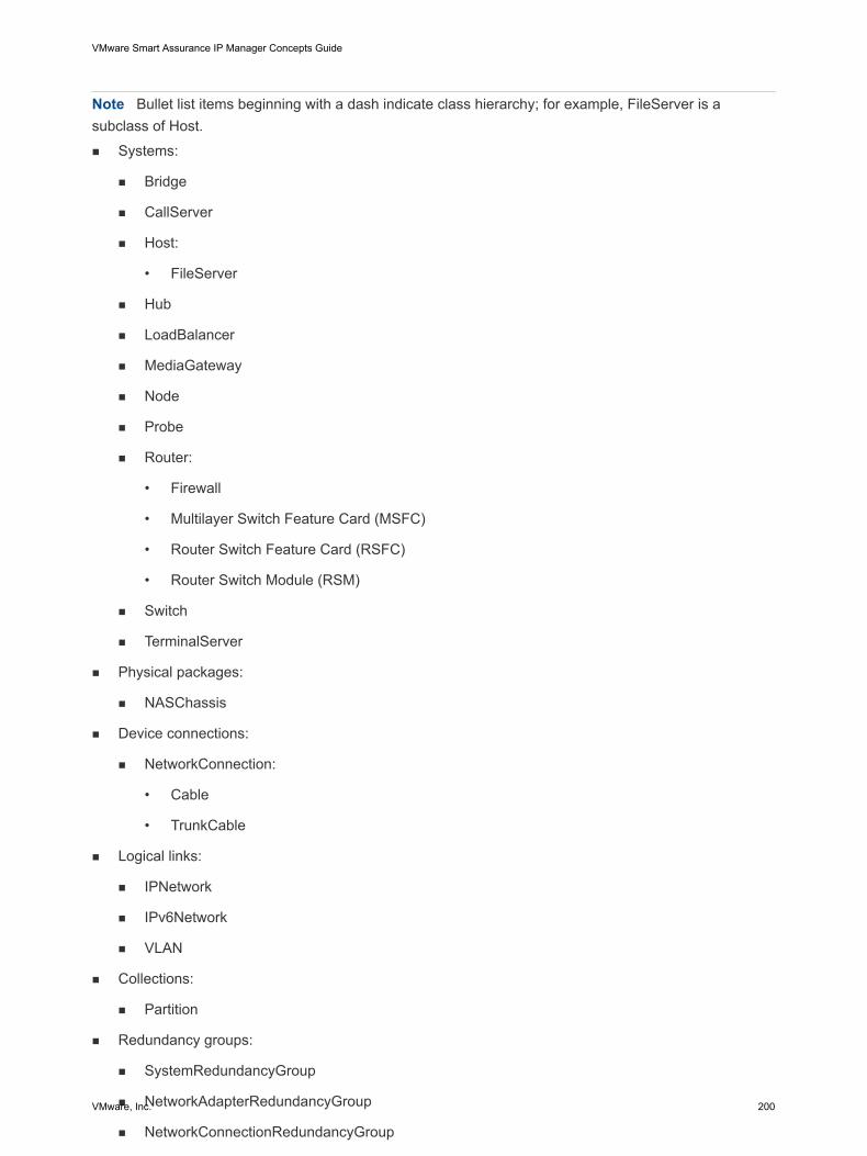
Note Bullet list items beginning with a dash indicate class hierarchy; for example, FileServer is asubclass of Host.n Systems:
n Bridge
n CallServer
n Host:
• FileServer
n Hub
n LoadBalancer
n MediaGateway
n Node
n Probe
n Router:
• Firewall
• Multilayer Switch Feature Card (MSFC)
• Router Switch Feature Card (RSFC)
• Router Switch Module (RSM)
n Switch
n TerminalServer
n Physical packages:
n NASChassis
n Device connections:
n NetworkConnection:
• Cable
• TrunkCable
n Logical links:
n IPNetwork
n IPv6Network
n VLAN
n Collections:
n Partition
n Redundancy groups:
n SystemRedundancyGroup
n NetworkAdapterRedundancyGroup
n NetworkConnectionRedundancyGroup
n HSRPGroup
n VRRPGroup
VMware Smart Assurance IP Manager Concepts Guide
VMware, Inc. 200
The Global Manager combines this topology with the topologies received from the other DomainManagers connected to the Global Manager. In some cases, depending on the other Domain Managers,combining means migrating certain object types imported from IP Availability Manager with certain objecttypes imported from the other Domain Managers.
Network topology in maps
The Global Console presents the topology information in a variety of dynamically updated formats thatshow the status of the network objects and their many relationships. One of those formats is the topologymap, which is a graphical representation of the topology.
Network topology map pop-up menus
Two types of pop-up menus are available in a network topology map:
n Right-click a selected node in a map
Opens a pop-up menu that enables you to select any of the map types available to the selected node(for example, Physical Connectivity, VLAN Connectivity, Group Membership), to display notificationproperties (if any) for the selected node, and so on.
For a node marked with a + (plus) sign, the Expand Node menu option allows you to expand the nodeto see all nodes that are physically or logically connected to the node.
n Right-click an open space in a map
Opens a pop-up menu that enables you to display a circular layout of the map, to manually positionnodes in the map, and so on. The Reset map menu option enables you to reset changes made to themap or to return to the saved map display.
In the topology tree of a Map Console, a pop-up menu is also available when you right-click an object.This menu enables you to select any of the map types available to the selected object, to displaynotification properties (if any) for the selected object, and so on.
The VMware Smart Assurance Service Assurance Manager Operator Guide provides detaileddescriptions of map menus and pop-up menus available for the Map Console.
Network topology map graphical representations
Network topology maps contain objects that may include IP networks, VLANs, routers, switches, hosts,and various types of connections such as cables and trunk cables. In a map display, a node is a graphicalrepresentation of a topology object, and an edge is a graphical representation of a relationship orconnection between objects.
Note that your system administrator may replace the standard map icons with other map icons that arepreferred by your organization. In that case, use Map > Map Legend to see the definitions of your mapicons.
Network topology map types
VMware Smart Assurance IP Manager Concepts Guide
VMware, Inc. 201
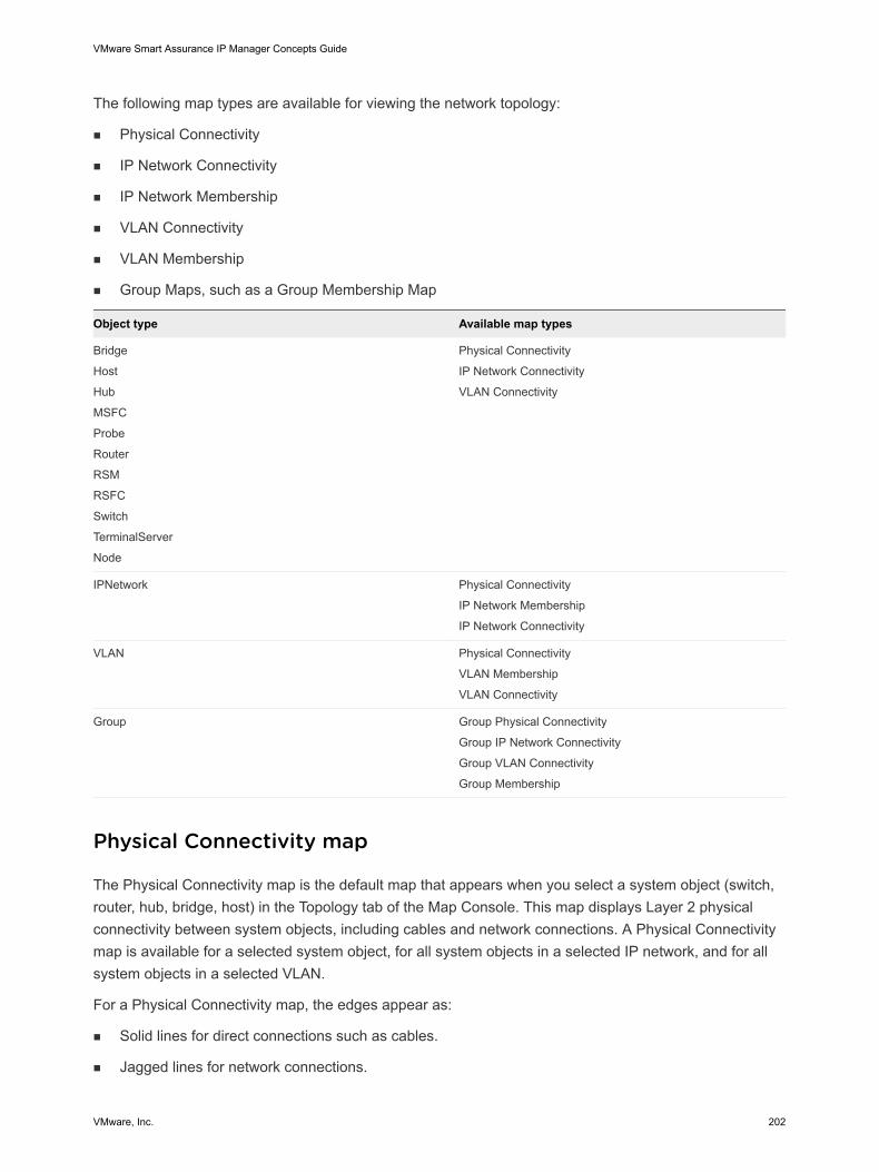
The following map types are available for viewing the network topology:
n Physical Connectivity
n IP Network Connectivity
n IP Network Membership
n VLAN Connectivity
n VLAN Membership
n Group Maps, such as a Group Membership Map
Object type Available map types
Bridge
Host
Hub
MSFC
Probe
Router
RSM
RSFC
Switch
TerminalServer
Node
Physical Connectivity
IP Network Connectivity
VLAN Connectivity
IPNetwork Physical Connectivity
IP Network Membership
IP Network Connectivity
VLAN Physical Connectivity
VLAN Membership
VLAN Connectivity
Group Group Physical Connectivity
Group IP Network Connectivity
Group VLAN Connectivity
Group Membership
Physical Connectivity map
The Physical Connectivity map is the default map that appears when you select a system object (switch,router, hub, bridge, host) in the Topology tab of the Map Console. This map displays Layer 2 physicalconnectivity between system objects, including cables and network connections. A Physical Connectivitymap is available for a selected system object, for all system objects in a selected IP network, and for allsystem objects in a selected VLAN.
For a Physical Connectivity map, the edges appear as:
n Solid lines for direct connections such as cables.
n Jagged lines for network connections.
VMware Smart Assurance IP Manager Concepts Guide
VMware, Inc. 202
If you display a Physical Connectivity map for a selected IP network or VLAN, the map displays thephysical connectivity of the system objects inside the IP network or VLAN. An icon representing theIP network or VLAN does not appear.
In a Physical Connectivity map, a hop is the distance between two system objects that are physicallyconnected.
IP Network Connectivity map
The IP Network Connectivity map is the default map that appears when you select an IP network in theTopology tab of the Map Console. It displays Layer 3 connectivity between routers and IP networks. An IPNetwork Connectivity map is available for a selected switch, router, RSM, hub, host, or IP network.
For an IP Network Connectivity map, the edges appear as:
n Solid lines for IP addresses for objects on the connected IP network.
n Jagged lines for network connections.
In an IP Network Connectivity map, a hop is a logical hop. It represents the distance between adevice and the IP network.
IP Network Membership map
The IP Network Membership map displays all objects having an IP address on a selected IP network. Theedges appear as solid lines for participation in the logical group and do not change color.
For an IP Network Membership map, the concept of a hop is not applicable.
VLAN Connectivity map
The VLAN Connectivity map is the default map that appears when you select a VLAN object in theTopology tab of the Map Console. It displays VLANs, the switches that participate in the VLAN, and therouters that enable connections between VLANs. A VLAN Connectivity map is available for a selectedswitch, router, RSM, hub, host, or VLAN.
For a VLAN Connectivity map, the edges appear as:
n Solid lines for devices connected to ports on a VLAN or switch.
n Jagged lines for network connections.
In a VLAN Connectivity map, a hop is a logical hop. It represents the distance between an object(router or switch) and the VLAN.
If a switch appears in a VLAN Connectivity map and no edge connects the switch to the VLAN, theswitch cannot recognize the VLAN even though the switch has another port that participates in theVLAN.
VLAN Membership map
VMware Smart Assurance IP Manager Concepts Guide
VMware, Inc. 203
The VLAN Membership map displays all devices that are members of a selected VLAN. The edgesappear as solid lines for participation in a selected VLAN and do not change color.
For a VLAN Membership map, the concept of a hop is not applicable.
Group maps
A group consists of one or more infrastructure devices, IP networks, VLANs, or subgroups. Groups arecreated by the administrator and might not be available for the session. The VMware Smart AssuranceService Assurance Manager Configuration Guide provides information about creating groups andimporting data for groups.
Four types of group maps exist:
n Group Physical Connectivity map — This map displays physical connectivity between group objects.The solid line edges between groups represent one or more physical connections between objects ofdifferent groups. The edges do not change color to reflect their state. The number of hops cannot bechanged.
n Group IP Network Connectivity map — In this map, an edge between two groups indicates that thereare one or more IP networks common to the two groups. The group icon containing the IP network isdisplayed; no IP network icon is displayed. The number of hops cannot be changed.
n Group VLAN Connectivity map — In this map, an edge between two groups indicates that there areone or more VLANs common to the two groups. The group icon containing the VLAN is displayed; noVLAN icon is displayed. The number of hops cannot be changed.
n Group Membership — This map displays all the objects of a selected group or a subgroup. Theedges do not appear. The concept of a hop is not applicable.
Network containment
An object’s Containment view appears in a dialog box that organizes the information for the object into tabpages and tables.
The intent of the Containment view is to allow users to examine detailed component topology of anindividual object. The Global Console retrieves the topology information from the Global Manager andfrom the underlying Domain Managers. If an underlying Domain Manager is not attached to the console,the console automatically establishes a connection to the Domain Manager by using the user’s login ID.
Opening a network containment dialog box
To obtain containment information about an individual network object, you can use any of the followingcommon methods to open a Containment dialog box for the object:
n In a network map tree, right-click the object and then select Containment in the pop-up menu.
n In a network map display, right-click the object and then select Containment in the pop-up menu.
VMware Smart Assurance IP Manager Concepts Guide
VMware, Inc. 204
n In a Topology Browser Console, right-click the object and then select Containment in the pop-upmenu.
n In a Notification Log Console, double-click a notification for the object and click the Containmentbutton in the Notification Properties dialog box.
In an object’s Containment view, the tabs that appear depend on which IP Managers are deployed,which feature licenses are installed, and which components are discovered.
Note Containment is not available for user-defined groups and services.
“Network containment tab pages” table in the VMware Smart Assurance IP Manager ReferenceGuide, provides information on Network classes, Containment tab pages, and the associatedattributes.
Root-cause problems, exceptions, and events
IP Availability Manager diagnoses root-cause problems and detects (computes) events from statuschanges gathered from or issued by devices in the managed environment. It uses the events assymptoms to diagnose root-cause problems.
Note Events used as symptoms to diagnose a failure can also be perceived as impacts resulting fromthe failure.
IP Availability Manager also generates exceptions, or aggregate events, where an exception is acollection of problems or events associated with a particular managed system, IPv6Network, or VLAN. IPAvailability Manager generates an exception whenever any of the composite problems or events for thesystem, IPv6Network, or VLAN occur. For example, IP Availability Manager will generate an exception fora router when a card on the router has a problem or the router is down.
The Global Manager imports all problems diagnosed by IP Availability Manager and certain key eventsdetected by IP Availability Manager. It also imports the IPv6Network inaccessible exception. The problemnotifications (one problem per notification), notifications (one event per notification), and IPv6Networkexception notifications (one exception per notification) are displayed in the Global Console.
The VMware Smart Assurance IP Manager Reference Guide provides information on key attributes,diagnosed problems, generated exceptions, and detected events for all categories of network objecttypes in the IP Availability Manager data model.
Trap analysis
A system or network adapter is considered to be unstable if it fluctuates too often between up and downstates over a short period of time.
VMware Smart Assurance IP Manager Concepts Guide
VMware, Inc. 205
The IP Availability Manager monitors a system or network adapter’s state through the SNMP traps itreceives and determines when to generate an unstable notification based on a combination of fixedvalues and user-controlled settings. The IP Availability Manager also calculates a stable time in which towait before clearing an Unstable notification.
IP Availability Manager monitors the following SNMP traps to determine a change in an object’s state:
n coldStart and warmStart traps for a system
n linkUp or linkDown traps for a network adapter
IP Availability Manager primarily uses linkDown traps for the analysis of unstable network adapters.However, for devices that only send linkUp traps, IP Availability Manager does use linkUp traps.When a device sends both linkUp and linkDown traps, IP Availability Manager uses linkDown trapsfor the unstable analysis.
Thresholds associated with unstable analysis
IP Availability Manager uses the following values to diagnose an object as unstable:
n Minimum Traps — The minimum number of Link/Restart traps received in order to conclude that theobject is unstable. This variable is set by the LinkTrapThreshold parameter (contained in theInterface/Port Flapping setting) for network adapters and the RestartTrapThreshold parameter(contained in the Connectivity setting) for systems.
n Trap Window — The period within which the Minimum Traps must be received to declare the objectunstable. This window is set by the LinkTrapWindow parameter (contained in the Interface/PortFlapping setting) for network adapters and the RestartTrapWindow parameter (contained in theConnectivity setting) for systems. After an object is declared unstable, IP Availability Managercomputes the Stable Time.
n Stable Time — The amount of time that must elapse without additional Link/Restart traps before IPAvailability Manager declares the object stable again. Stable Time depends on the length of time thatthe object was unstable. This is at least as large as the unstable length of time, and at least as largeas the Trap Window. However, the stable time cannot be longer than 1 hour.
Example of unstable analysis
Unstable system/network adapter diagnosis illustrates how a system or network adapter is diagnosed asbeing unstable.
1 Up
2 Down
3 80 secs
4 idle
5 1st Trap
6 Last Trap
VMware Smart Assurance IP Manager Concepts Guide
VMware, Inc. 206
7 idle
8 waiting
9 Send
10 Unstable
11 Notification
12 Clear
13 Unstable
14 Notification
15 80 secs
16 unstable
Figure 6-1. Unstable system/network adapter diagnosis
In the example, assume that the Link/RestartTrapWindow parameter has a value of 30 seconds and thatthe Link/RestartTrapThreshold parameter has a value of 2.
IP Availability Manager performs the following actions:
1 As soon as IP Availability Manager receives a linkDown trap from a physical port or interface (or acoldStart/warmStart trap from a system), it begins counting.
2 When IP Availability Manager receives two or more traps within the 30-second Trap Window, itconsiders the network adapter or system to be unstable and sends an Unstable notification. TheMinimum Traps variable (set by the Link/RestartTrapWindow parameter) determines the number oftraps (2) that IP Availability Manager must receive within the Trap Window (set by the Link/RestartTrapWindow parameter) before IP Availability Manager considers an object unstable.
3 IP Availability Manager continues to receive traps for 80 seconds after the initial trap. This results in aStable Time of 80 seconds.
The Stable Time is the amount of time IP Availability Manager waits before it clears the Unstablenotification. In our example, the Stable Time is set at 80 seconds since it is greater than the TrapWindow (30 seconds) and less than one hour.
As you can see, IP Availability Manager uses a relative measure to determine how long an objectmust be stable before it clears the Unstable notification. This measure is proportional to the amount oftime an object is unstable. The longer an object is unstable the longer it must be stable before theUnstable notification is cleared. Because the object in our example remains unstable for 80 seconds,IP Availability Manager clears the Unstable notification no sooner than 80 seconds after it receivesthe final trap.
Unstable notifications for backup or dial-on-demand interfaces
VMware Smart Assurance IP Manager Concepts Guide
VMware, Inc. 207
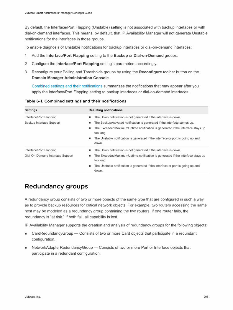
By default, the Interface/Port Flapping (Unstable) setting is not associated with backup interfaces or withdial-on-demand interfaces. This means, by default, that IP Availability Manager will not generate Unstablenotifications for the interfaces in those groups.
To enable diagnosis of Unstable notifications for backup interfaces or dial-on-demand interfaces:
1 Add the Interface/Port Flapping setting to the Backup or Dial-on-Demand groups.
2 Configure the Interface/Port Flapping setting’s parameters accordingly.
3 Reconfigure your Polling and Thresholds groups by using the Reconfigure toolbar button on theDomain Manager Administration Console.
Combined settings and their notifications summarizes the notifications that may appear after youapply the Interface/Port Flapping setting to backup interfaces or dial-on-demand interfaces.
Table 6-1. Combined settings and their notifications
Settings Resulting notifications
Interface/Port Flapping
Backup Interface Support
n The Down notification is not generated if the interface is down.
n The BackupActivated notification is generated if the interface comes up.
n The ExceededMaximumUptime notification is generated if the interface stays uptoo long.
n The Unstable notification is generated if the interface or port is going up anddown.
Interface/Port Flapping
Dial-On-Demand Interface Support
n The Down notification is not generated if the interface is down.
n The ExceededMaximumUptime notification is generated if the interface stays uptoo long.
n The Unstable notification is generated if the interface or port is going up anddown.
Redundancy groups
A redundancy group consists of two or more objects of the same type that are configured in such a wayas to provide backup resources for critical network objects. For example, two routers accessing the samehost may be modeled as a redundancy group containing the two routers. If one router fails, theredundancy is “at risk.” If both fail, all capability is lost.
IP Availability Manager supports the creation and analysis of redundancy groups for the following objects:
n CardRedundancyGroup — Consists of two or more Card objects that participate in a redundantconfiguration.
n NetworkAdapterRedundancyGroup — Consists of two or more Port or Interface objects thatparticipate in a redundant configuration.
VMware Smart Assurance IP Manager Concepts Guide
VMware, Inc. 208
n NetworkConnectionRedundancyGroup — Consists of two or more NetworkConnection, Cable, orTrunkCable objects that participate in a redundant configuration.NetworkConnectionRedundancyGroups (NCRG) are simply reference classes, they are not createdduring discovery. There is only one relationshipset: ComposedOf/PartOf between members of theNetworkConnection class. If that is populated, the typical events (ReducedRedundancy, AtRisk,AllComponentsDown) work as expected.
n SystemRedundancyGroup — Consists of two or more system (Switch, Router, Hub, Bridge, Host)objects that participate in a redundant configuration.
n HSRPGroup — Consists of two or more Cisco devices that support the Hot Standby Router Protocol(HSRP) and are configured to ensure that user traffic recovers immediately and transparently fromfirst hop failures in network edge devices or access circuits. The devices are connected to the samesegment of a network and, using HSRP, work together to present the appearance of a single routeron the LAN. The devices in an HSRPGroup share an IP address and a MAC (Layer 2) address.
n VRRPGroup — Consists of two or more VRRP enabled routers. The VRRPGroup is created for eachVirtual Router Identifier (VRID) and is composed of a logical element defined per interface perVRRPGroup on a VRRP router called VRRPEndpoint. VRRPEndpoints belonging to the sameVRRPGroup (that is, having the same VRID) have a common virtual IP and a Virtual MAC. TheVirtual MAC is defined as xx-xx-xx-xx-xx-VRID.
Card redundancy groups
IP Availability Manager automatically creates CardRedundancyGroups during discovery for Cisco devicesthat support the CISCO-STACK-MIB. Each such group consists of two cards. You can view the cardredundancy groups and their members by using the Domain Manager Administration Console.
In addition, you can create redundancy groups for cards that do not support the CISCO-STACK-MIB. Theprocess for manually creating a card redundancy group is similar to that for creating a system redundancygroup, described in the following section. First, create an instance of the CardRedundancyGroup classand then insert the cards that participate in the redundancy group into the ComposedOf relationship.
System redundancy groups
Redundancy groups for network adapters, network connections, and systems must be manually createdby using the dmctl utility or an Adapter Scripting Language (ASL) script.
To create a redundancy group for one of these types of objects:
1 Create an instance of one of the redundancy group classes.
2 Insert the objects that participate in the redundancy group into the ComposedOf relationship of theredundancy group.
The following example uses the dmctl utility to create an instance of a system redundancy group andinserts two members into the group:
/opt/InCharge7/IP/smarts/bin/dmctl -s INCHARGE-AM-PM
Server INCHARGE-AM-PM User: admin
VMware Smart Assurance IP Manager Concepts Guide
VMware, Inc. 209
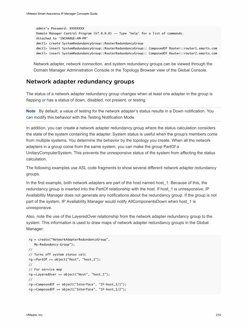
admin's Password: XXXXXXXX
Domain Manager Control Program (V7.0.0.0) -- Type 'help' for a list of commands.
Attached to 'INCHARGE-AM-PM'
dmctl> create SystemRedundancyGroup::RouterRedundancyGroup
dmctl> insert SystemRedundancyGroup::RouterRedundancyGroup:: ComposedOf Router::router1.smarts.com
dmctl> insert SystemRedundancyGroup::RouterRedundancyGroup:: ComposedOf Router::router2.smarts.com
Network adapter, network connection, and system redundancy groups can be viewed through theDomain Manager Administration Console or the Topology Browser view of the Global Console.
Network adapter redundancy groups
The status of a network adapter redundancy group changes when at least one adapter in the group isflapping or has a status of down, disabled, not present, or testing.
Note By default, a value of testing for the network adapter’s status results in a Down notification. Youcan modify this behavior with the Testing Notification Mode.
In addition, you can create a network adapter redundancy group where the status calculation considersthe state of the system containing the adapter. System status is useful when the group's members comefrom multiple systems. You determine the behavior by the topology you create. When all the networkadapters in a group come from the same system, you can make the group PartOf aUnitaryComputerSystem. This prevents the unresponsive status of the system from affecting the statuscalculation.
The following examples use ASL code fragments to show several different network adapter redundancygroups.
In the first example, both network adapters are part of the host named host_1. Because of this, theredundancy group is inserted into the PartOf relationship with the host. If host_1 is unresponsive, IPAvailability Manager does not generate any notifications about the redundancy group. If the group is notpart of the system, IP Availability Manager would notify AllComponentsDown when host_1 isunresponsive.
Also, note the use of the LayeredOver relationship from the network adapter redundancy group to thesystem. This information is used to draw maps of network adapter redundancy groups in the GlobalManager:
rg = create("NetworkAdapterRedundancyGroup",
My-Redundancy-Group");
//
// Turns off system status calc
rg->PartOf += object("Host", "host_1");
//
// For service map
rg->LayeredOver += object("Host", "host_1");
//
rg->ComposedOf += object("Interface", "IF-host_1/1");
rg->ComposedOf += object("Interface", "IF-host_1/2");
VMware Smart Assurance IP Manager Concepts Guide
VMware, Inc. 210
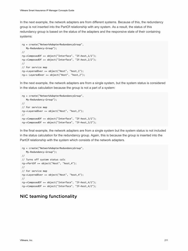
In the next example, the network adapters are from different systems. Because of this, the redundancygroup is not inserted into the PartOf relationship with any system. As a result, the status of thisredundancy group is based on the status of the adapters and the responsive state of their containingsystems:
rg = create("NetworkAdapterRedundancyGroup",
My-Redundancy-Group");
//
rg->ComposedOf += object("Interface", "IF-host_1/1");
rg->ComposedOf += object("Interface", "IF-host_2/2");
//
// For service map
rg->LayeredOver += object("Host", "host_1");
rg-> LayeredOver += object("Host", "host_2");
In the next example, the network adapters are from a single system, but the system status is consideredin the status calculation because the group is not a part of a system:
rg = create("NetworkAdapterRedundancyGroup",
My-Redundancy-Group");
//
// For service map
rg->LayeredOver += object("Host", "host_3");
//
rg->ComposedOf += object("Interface", "IF-host_3/1");
rg->ComposedOf += object("Interface", "IF-host_3/2");
In the final example, the network adapters are from a single system but the system status is not includedin the status calculation for the redundancy group. Again, this is because the group is inserted into thePartOf relationship with the system which consists of the network adapters.
rg = create("NetworkAdapterRedundancyGroup",
My-Redundancy-Group");
//
// Turns off system status calc
rg->PartOf += object("Host", "host_4");
//
// For service map
rg->LayeredOver += object("Host", "host_4");
//
rg->ComposedOf += object("Interface", "IF-host_4/1");
rg->ComposedOf += object("Interface", "IF-host_4/2");
NIC teaming functionality
VMware Smart Assurance IP Manager Concepts Guide
VMware, Inc. 211
The primary purpose of the NIC teaming functionality is that when a teamed NIC is employed, thestandard MIB-II tables only represent the logical (teamed) NIC. This inherently inhibits the creation of L2connectivity between the Host, with the teamed NICs, and the adjacent switch or switches. The reason isthat the same logical MAC is observed on multiple access ports. The NIC teaming functionality pulls thephysical NIC information (including the BIM - Burned-in MAC) from the Enterprise MIBs and creates aNetworkAdapterRedundancyGroup to represent the logical grouping of the physical NICs. This allows L2Cable connections to form normally with adjacent Switches.
Note NIC teaming is possible for a number of different media types. However, the primary focus is onattempting to solve the issue for Ethernet-media devices.
NIC teaming support is applicable specifically to device specific discovery. NIC teaming support occurs atthree different points in IP Availability Manager which are as follows:
n IP Availability Manager initialization — This involves loading of the various meta-data to providenetwork access redundancy and allow rapid convergence when a failure occurs.
n oid2Type configuration — This involves defining the specific probes to be launched for the vendorsthat are supported.
n Discovery probes — This involves additional data collection handled through the normal additionaldiscovery probes.
Upon discovery of the device (host) that is configured for NIC teaming, a redundancy group namely,NetworkAdapterRedundancyGroup is created in the IP Availability Manager. ANetworkAdapterRedundancyGroup consists of two or more port or interface objects that participate ina redundant configuration (NIC teaming). The NARG (NetworkAdapterRedundancyGroup) can indeedconsist of Ports or Interfaces, but the members of the teamed NIC will always be created asInterfaces:
Relationship: The NetworkAdapterRedundancyGroup has a ComposedOf relationship with Interfacesand Interfaces have a PartOf relationship with NetworkAdapterRedundancyGroup.
Network adapter redundancy group for NIC Teaming
NIC teaming functionality provides network access redundancy and allows for rapid convergence when afailure occurs. NIC teaming is the process of grouping together several physical NICs (Network InterfaceCards) into one single logical NIC, which can be used for network fault tolerance and/or transmission loadbalancing. In a team of two or more NICs, the secondary NIC assumes the primary or active role, if theprimary NIC fails. However, failover will not occur unless the primary NIC is specified.
NIC teaming has two purposes:
n Fault Tolerance: By binding more than one physical NIC to a logical NIC, high availability ismaximized. Even if one NIC fails, the network connection does not cease and continues to operate onother NICs.
VMware Smart Assurance IP Manager Concepts Guide
VMware, Inc. 212
n Load Balancing: Balancing the network traffic load on a server can enhance the functionality of theserver and the network. Load balancing within a network interconnect controller (NIC) team enablesdistributing traffic amongst the members of the NIC team so that traffic is routed among all availablepaths. In most scenarios of Load Balancing, it is required that teamed connections usually terminateon the same remote device and that the device has an Etherchannel (or equivalent protocol)configured.
HSRPGroups
During discovery, IP Availability Manager automatically creates HSRPGroups for Cisco devices thatsupport the CISCO-HSRP-MIB and are configured in an HSRPGroup. Each such group is composed oftwo or more routers and their interfaces.
You can view the HSRPGroups and their members by using the Domain Manager Administration Consoleand the Global Console. Analysis and monitoring of a HSRPGroup occurs automatically after the group iscreated and its member routers are inserted into the group.
VRRP Groups
During discovery of the VRRP enabled routers, IP Availability Manager creates a new redundancy groupcalled VRRPGroup. The VRRPGroup is created for each Virtual Router Identifier (VRID). It is composedof a logical element defined per interface per VRRPGroup on a VRRP router called VRRPEndpoint.VRRPEndpoints belonging to the same VRRPGroup (that is, having the same VRID) have a commonvirtual IP and a Virtual MAC. The Virtual MAC is defined as xx-xx-xx-xx-xx-VRID. The VRRP-enabledrouter having the highest priority is considered as the master router and all other routers are consideredas backup routers.
Note Virtual IP of VRRP is derived from vrrpAssoIpAddr, which is part of Indexes invrrpAssoIpAddrTable. If the vrrpAssoIpAddrTable does not contain values in the MIB, then VRRPGroupwill not be created. If ipNetToMediaTable does not contain values with current Virtual IP for thatVRRPGroup, then relationships like HostedBy, LayeredOver, ConnectedVia, Underlying,ConcreteDependency_Dependent will not be created.
Basic VRRP Configuration
Basic VRRP configuration illustrates the basic VRRP configuration.
VMware Smart Assurance IP Manager Concepts Guide
VMware, Inc. 213
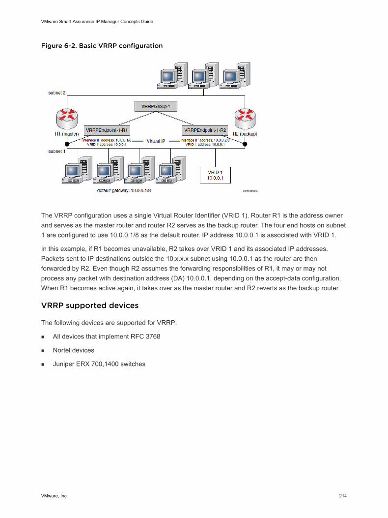
Figure 6-2. Basic VRRP configuration
The VRRP configuration uses a single Virtual Router Identifier (VRID 1). Router R1 is the address ownerand serves as the master router and router R2 serves as the backup router. The four end hosts on subnet1 are configured to use 10.0.0.1/8 as the default router. IP address 10.0.0.1 is associated with VRID 1.
In this example, if R1 becomes unavailable, R2 takes over VRID 1 and its associated IP addresses.Packets sent to IP destinations outside the 10.x.x.x subnet using 10.0.0.1 as the router are thenforwarded by R2. Even though R2 assumes the forwarding responsibilities of R1, it may or may notprocess any packet with destination address (DA) 10.0.0.1, depending on the accept-data configuration.When R1 becomes active again, it takes over as the master router and R2 reverts as the backup router.
VRRP supported devices
The following devices are supported for VRRP:
n All devices that implement RFC 3768
n Nortel devices
n Juniper ERX 700,1400 switches
VMware Smart Assurance IP Manager Concepts Guide
VMware, Inc. 214
Performance Manager andServer Performance Manager 7This chapter includes the following topics:
n About IP Performance Manager
n Performance monitoring
n Performance analysis
n Performance notifications
n Before you start
n SNMP traps processed
n DisplayName and Name attributes
About IP Performance Manager
Knowing the health of the network objects in your network is crucial to ensuring optimum networkperformance. Constant monitoring, especially of critical ports in the network, is necessary to detect whenperformance deteriorates so that you can take appropriate corrective action.
IP Performance Manager monitors the performance of Layer 2 and Layer 3 network objects in switchedand routed networks, and automates the analysis of faults using performance thresholds. Faults canoccur in systems (switches, routers, hubs, bridges, and hosts) and in network adapters (ports andinterfaces). When a performance threshold is exceeded, IP Performance Manager generates a system-level exception notification.
Note Thresholds can be set in the Polling and Thresholds tab in the Domain Manager AdministrationConsole. The VMware Smart Assurance IP Manager User Guide provides information on how to setthresholds.
For example, when a particular network adapter exceeds the ErrorThreshold, IP Performance Managernotifies HighErrorRate fault for network adapter and generates an ErrorException for the system thatcontains the network adapter. In addition, if the network adapter is a member of a Virtual Local AreaNetwork (VLAN), IP Performance Manager also generates the exception notification at the VLAN level.
Performance monitoring
VMware, Inc. 215
After the initial discovery and modeling of the network, IP Performance Manager continuously monitorsthe status of the discovered systems using:
n Internet Control Message Protocol (ICMP) polling
n Simple Network Management Protocol (SNMP) polling
IP Performance Manager also processes SNMP trap messages received from the network to obtainstatus information for the discovered systems.
The VMware Smart Assurance IP Manager Reference Guide provides information about the MIBspolled and SNMP traps processed by the IP Performance Manager.
Performance analysis
IP Performance Manager retrieves fault-related, intra-system information from each network object anduses that information to conduct performance analysis.
Performance notifications
IP Performance Manager exports the results of its network performance analysis to the Global Managerin the form of notifications, which are displayed in the Notification Log Console view of the GlobalConsole. The notifications identify IP Performance Manager by its domain name in the Source attributeand also the IP Performance Manager can be identified by its domain manager group. Users can double-click a notification to view detailed information about the notification.
IP Performance Manager creates three types of notifications: faults, events, and exceptions. Exceptionsare also referred to as aggregate events.
n A fault indicates a performance problem detected by IP Performance Manager. Examples of faultsare:
n HighErrorRate for a network adapter
n HighUtilization of a switch’s backplane
n HighBufferMissRate on a system’s memory component
n An event indicates an abnormal condition detected by IP Performance Manager.
n An exception indicates that one or more faults are occurring in a particular system or VLAN.
VMware Smart Assurance IP Manager Concepts Guide
VMware, Inc. 216
The VMware Smart Assurance IP Manager User Guide provides information about viewing thenotifications, and the VMware Smart Assurance IP Manager Reference Guide provides descriptionsand examples of the types of faults detected by IP Performance Manager.
Note You view the impacts for a network problem notification by clicking the Impact tab in theNotification Properties dialog box. The Impact tab lists all of the affected objects for the notification.Because IP Performance Manager does not diagnose root-cause problems, it does not diagnoseimpacts. Therefore, the Notification Properties dialog box for notifications generated by IPPerformance Manager does not contain the Impact tab.
Before you start
The Network Objects and Their Failures section in the VMware Smart Assurance IP Manager ReferenceGuide identifies the topology objects discovered and the events notified by the IP Performance Manager.
Console operations are controlled by certain console operation options such as Notification Properties,Expand Map Node, and Show Containment. The VMware Smart Assurance Service Assurance ManagerConfiguration Guide provides instructions on changing the console operations.
IP Performance Manager also instantiates device connection, collection, management agent, andredundancy group object types, but because IP Performance Manager does no analysis for these objecttypes, they are not discussed here. The VMware Smart Assurance IP Manager Reference Guidedescribes all of the object types instantiated by IP Performance Manager.
All of the object types instantiated by IP Performance Manager are available to a Global Consoleattached to IP Performance Manager, and a subset are available to a Global Console attached to theGlobal Manager. The VMware Smart Assurance IP Manager Reference Guide provides a list of the objecttypes imported by the Global Manager.
SNMP traps processed
IP Performance Manager processes data found in the following fields of each SNMP trap message:
n Enterprise (the sysObjectID of the agent/object)
n Generic Trap Identifier
n Specific Trap Identifier
n Variable-Bindings
n IP address of the SNMP agent
IP Performance Manager uses trap messages for two purposes:
n Discovery
n Analysis
VMware Smart Assurance IP Manager Concepts Guide
VMware, Inc. 217
SNMP traps processed for discovery
A trap message processed for discovery purposes conveys one of the following conditions for a device inthe managed network:
n A device, not yet in the modeled topology, was started.
n A device, already in the modeled topology, was equipped with an additional field replaceable unit(FRU) or had an FRU removed; for example, a card was inserted into the device.
n A device, already in the modeled topology, had a TCP connection closed by a remote application; forexample, a Telnet session to the device was terminated.
SNMP traps processed for analysis
A trap message processed for analysis purposes pertains to a device that has been discovered andtherefore is already in the modeled topology. IP Performance Manager extracts the information from thetrap message and updates the appropriate device attributes.
Note IP Performance Manager uses trap messages and the results obtained from periodic SNMP pollingto detect network degradations that adversely affect network performance.
Chapter 3, MIBs Polled and SNMP Traps Processed, in the VMware Smart Assurance IP ManagerReference Guide, provides more information.
DisplayName and Name attributes
Each network object has a unique name, which is defined by the DisplayName and Name attributes forthe object.
Naming convention for network objects
For a discovered system, IP Performance Manager uses a consistent naming convention to assign thesystem and each of its components a unique name. The name assigned to a system is determined by thesetting of the NameFormat parameter in the name-resolver.conf file, which is located in the BASEDIR/smarts/conf/discovery directory. The assigned name becomes the value of the system’s Name attribute.Refer How discovery names a system for information about the name resolution process used to name asystem.
Note The values of a system’s Name attribute and DisplayName attribute may be different, dependingon the setting of the DisplayNameFormat parameter in the discovery.conf file. The VMware SmartAssurance IP Manager Reference Guide describes the configuration parameters in the discovery.conf file.
To name a discovered network object, IP Performance Manager uses the appropriate naming format. Thenaming formats are the default naming conventions. If no naming format is listed for the Display Name,the naming format is the same as the one listed for Name.
VMware Smart Assurance IP Manager Concepts Guide
VMware, Inc. 218
NAS 8This chapter includes the following topics:
n Introduction to network-attached storage
n The VMware Smart Assurance IP NAS solution
n NAS IP discovery
n Celerra devices for NAS Extension functionality
n Scenarios
n NAS notifications
n NAS topology map
n NAS containment
Introduction to network-attached storage
Network-attached storage along with storage area networks (SANs) are increasingly important asenterprise storage solutions. SANs are optimized for high-volume block-oriented data transfers, whileNAS provides storage services for applications that access data at the file level. Network-attachedstorage systems include centrally managed servers and an operating system that is optimized for fast fileaccess and heterogeneous file sharing over an IP network.
NAS provides facilities for high availability, rapid recovery, data protection, ease of management, and databackup and recovery. NAS is typically implemented for messaging, development applications, businessand regulatory compliance, and general file sharing. NAS is flexible and extensible, allowing for theaddition of storage devices to a network, as needed.
A NAS system includes a network server, file servers, and software for configuring and mapping filelocations to the network-attached devices. Each NAS device is attached to a local area network (typically,an Ethernet network) and assigned an IP address. The storage system may be a separate back-endsystem connected either logically or physically to the NAS system.
A NAS system discovers Control Station as a host through SNMP and gets information on file serversusing HTTP adapter. A logical entity called NASChassis will PackageSystem host and fileservers.
Overview of the IP Availability Manager Extension for NAS
VMware, Inc. 219
The VMware Smart Assurance IP Availability Manager Extension for NAS (NAS Extension) is applied toan existing IP Availability Manager installation. After installation, the Availability Manager can discoverNAS devices, and perform root cause and impact analysis on these devices.
The VMware Smart Assurance Installation Guide for SAM, IP, ESM, MPLS, and NPM Managers providesinformation on installation and startup issues for the IP Availability Manager Extension for NAS. The guidealso provides information on how to install and start the HTTPS Adapter service.
With the NAS Extension, the Availability Manager discovers and models network-attached storagedevices as IP devices. Supported systems include VMware Celerra®systems (Data Movers and ControlStations), and Network Appliance (NetApp) Filers.
The Availability Manager with the NAS Extension identifies IP-related failures, diagnoses root causeproblems, and calculates the impacts of failures.
To discover and monitor the NAS topology, the Availability Manager reads configuration information withinthe Celerra Network Server using the HTTPS Adapter, an XML/HTTPS discovery probe. The VMwareSmart Assurance Global Console displays the topology, notifications, and maps related to both the IP andNAS elements.
The NAS Extension is implemented through the IP Availability Manager and Service Assurance Manager.
Certified NAS Devices
The following devices are certified for use with the IP Availability Manager Extension for NAS:
n Celerra CNS, NS series, and NSX, with NAS release 4.0 and later.
Note To support NAS Extension management functionality, the Celerra Control Station must supportXHMP service and have HTTPS enabled.
n NetApp: F700, F800 and F900 series with ONTAP 6.1—6.5
VMware Celerra devices
Celerra is a high performance IP storage platform. It delivers NAS (Network Attached Storage) and iSCSIcapabilities to consolidate application storage and file servers in either an integrated configuration, or as agateway connected to a CLARiiON or Symmetrix storage system.
A Celerra installation includes the following IP-related devices:
n Celerra Network Server
n Celerra Control Station.
n Celerra Data Movers
NAS device relationships shows these relationships.
VMware Smart Assurance IP Manager Concepts Guide
VMware, Inc. 220
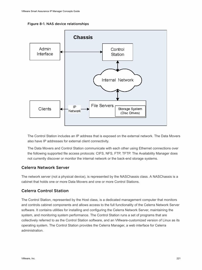
Figure 8-1. NAS device relationships
The Control Station includes an IP address that is exposed on the external network. The Data Moversalso have IP addresses for external client connectivity.
The Data Movers and Control Station communicate with each other using Ethernet connections overthe following supported file access protocols: CIFS, NFS, FTP, TFTP. The Availability Manager doesnot currently discover or monitor the internal network or the back-end storage systems.
Celerra Network Server
The network server (not a physical device), is represented by the NASChassis class. A NASChassis is acabinet that holds one or more Data Movers and one or more Control Stations.
Celerra Control Station
The Control Station, represented by the Host class, is a dedicated management computer that monitorsand controls cabinet components and allows access to the full functionality of the Celerra Network Serversoftware. It contains utilities for installing and configuring the Celerra Network Server, maintaining thesystem, and monitoring system performance. The Control Station runs a set of programs that arecollectively referred to as the Control Station software, and an VMware-customized version of Linux as itsoperating system. The Control Station provides the Celerra Manager, a web interface for Celerraadministration.
VMware Smart Assurance IP Manager Concepts Guide
VMware, Inc. 221
Celerra Control Station is discovered as a Host by IP. Host (Celerra control system) is defined bySystemsPackagedIn relationship with NASChassis. Conversely, NASChassis has a PackagesSystemsrelationship with FileServer and Host.
Celerra File Servers or Data Mover
The Data Movers, represented by the FileServer class, are the Celerra components that transfer databetween the storage system and the network client. A Celerra Network Server can have from one to 14Data Movers.The Data Movers are managed via the Control Station.
A Data Mover can be active (also called primary) or, in a Celerra Network Server model that supportsmultiple Data Movers, can be a standby for other Data Movers.
Each Data Mover is independent; there is no communication between Data Movers. If a Data Mover fails,the Control Station manages the failover to the standby Data Mover, assuming a standby has beenconfigured.
A Data Mover and the Control Station communicate with each other using both Ethernet and serialconnections. A Data Mover communicates with the network using network interface cards (NICs), whichmay support 10/100/1000Base T Ethernet or optical Gigabit Ethernet.
A Data Mover communicates with the back-end data storage systems using Fibre Channel connections.In the Celerra Clustered Network Server, storage processing is provided by a component of the DataMover, a Fibre Channel HBA card, that connects to the storage array through a Fibre Channel switch. Inthe Celerra NS series, storage processing is provided by an auxiliary storage processor enclosurecontaining two storage processors.
Celerra File Servers or Data Movers are discovered as its FileServers by IP. A FileServer is defined byComposedOf relationship with FileSystem. Conversely, a FileSystem is defined by PartOf relationshipwith FileServer.
NetApp Filer
NetApp Filers, also represented by the FileServer Class, are the NetApp storage systems. These devicescombine file system technology with a proprietary operating system that provides for management as wellas optimized storage utilization.
The VMware Smart Assurance IP NAS solution
The IP NAS solution architecture consists of the following components:
n IP Availability Manager — A Domain Manager that discovers, monitors, and analyzes failures in theunderlying IP network. With the NAS Extension applied, the Availability Manager discovers andmonitors NAS devices, correlates events, diagnoses root-cause problems, and calculates impacts.
n Global Manager — Abstracts and consolidates information from the Domain Managers anddeduplicates notifications.
n Global Console — Provides display capability for notifications, maps, and other graphical information.
VMware Smart Assurance IP Manager Concepts Guide
VMware, Inc. 222
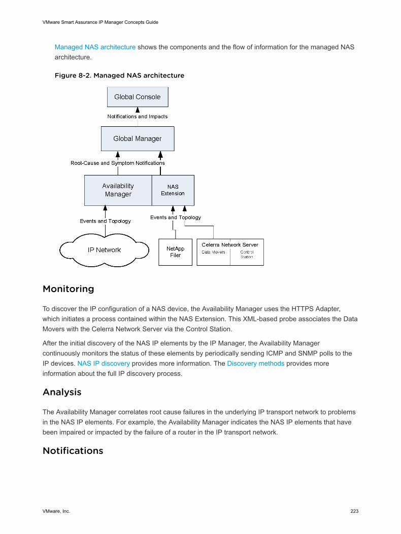
Managed NAS architecture shows the components and the flow of information for the managed NASarchitecture.
Figure 8-2. Managed NAS architecture
Monitoring
To discover the IP configuration of a NAS device, the Availability Manager uses the HTTPS Adapter,which initiates a process contained within the NAS Extension. This XML-based probe associates the DataMovers with the Celerra Network Server via the Control Station.
After the initial discovery of the NAS IP elements by the IP Manager, the Availability Managercontinuously monitors the status of these elements by periodically sending ICMP and SNMP polls to theIP devices. NAS IP discovery provides more information. The Discovery methods provides moreinformation about the full IP discovery process.
Analysis
The Availability Manager correlates root cause failures in the underlying IP transport network to problemsin the NAS IP elements. For example, the Availability Manager indicates the NAS IP elements that havebeen impaired or impacted by the failure of a router in the IP transport network.
Notifications
VMware Smart Assurance IP Manager Concepts Guide
VMware, Inc. 223
The Availability Manager reports its analysis results to the Global Manager in the following types ofnotifications: root-cause problem notifications, symptomatic event notifications, and aggregate eventnotifications.
Relevant notifications are displayed in the Notification Log Console view of the Global Console. Root-cause failures diagnosed by the Availability Manager display a value of “Yes” for the value of the IsRootattribute and identify the Availability Manager by its domain name in the Source attribute.
Impacts
The Availability Manager calculates the Impacts that the failures of one managed element may have onother managed elements. Impact information is included in notifications.
NAS IP discovery
The Availability Manager with the NAS Extension uses standard ICMP (Ping) and SNMP probes todetermine device status and containment information. In addition, the NAS Extension uses an HTTPSAdapter to gather configuration information about Celerra Control Station devices, and some post-processing steps to complete the topology creation.
File Servers present in different networks can be discovered in different IP Managers. During post-processing the fileservers are related to the NASChassis.
Note The internal Celerra IP network (the IP network that supports communication between file serversand the control station hosts) is automatically excluded from discovery.
ICMP and SNMP probes
The ICMP probe determines whether a device is operational.
The SNMP probe uses the management, MIB-2, system information to determine the type of device. Ifthe NAS Extension determines that the device is a Control Station, the Availability Manager launches theHTTPS Adapter probe. In addition, if the MIBs are included in the SNMP Agent of the device, the SNMPprobe gathers containment information about the device’s interfaces and IP address.
HTTPS/XML discovery probe
The HTTPS Adapter gathers information about Celerra devices that are unavailable through theAvailability Manager SNMP probes. When the Availability Manager encounters a NAS device duringdiscovery, it launches a probe that queries the Control Station for information such as the associatedFileServers and software version.
Discovery in the domain manager
IP Manager discovers the Control Station and gets the list of file servers and its details through HTTPadapter, this information is cached in the NASChassis class.
VMware Smart Assurance IP Manager Concepts Guide
VMware, Inc. 224
The Control Station objects such as, Host, fileserver, and NASChassis will be created in the IP Manager.
Note When the Host (Control Station) is discovered from IP Manager, both the Host (Control Station)and File Server (Data Mover) objects are moved to the pending list, as UNDISCOVERED although thehost is present in the topology. When the Data Movers are discovered, all the NAS devices are removedfrom the pending list.
NAS post processing
Post-processing creates the NAS topology as follows:
n Sets the NASChassis object display name
n Sets IP Address, Software Version, Slots and Standby.
n Sets the FileServer object display name
n Sets the Host (Control Station) object display name
n Deletes obsolete NASChassis, FileServer and Host (Control Station) objects
The IP Availability Manager associates Host objects (Control Stations) and FileServer objects(Celerra Data Movers) with the NASChassis object.
In addition, the Availability Manager establishes relationships between these components and theunderlying IP network.
The NAS topology is stored in the Repository and displayed on the Global Console using theTopology Browser and various maps. For more information, refer to NAS notifications.
Celerra devices for NAS Extension functionality
To support NAS Extension functionality, you may need to configure the following:
n Control Station and Data Mover IP addresses
n Control Station usernames and passwords
Control Station and Data Mover IP addresses
The IP Availability Manager Extension for NAS requires access to the Control Station and Data Mover IPaddresses that are exposed on the external network. You configure the IP addresses after the devices arecabled to the network switches.
For information about cabling the Celerra Network Server, refer to the Celerra NS500/NS600/NS700/NS704 Integrated Configuration Version 5.4 Setup Guide.
The Configuring and Managing Celerra Networking and Configuring and Managing Celerra Network HighAvailability technical modules provide more information about how to configure the external IP addressesonce the cables are in place.
VMware Smart Assurance IP Manager Concepts Guide
VMware, Inc. 225
Control Station usernames and passwords
When using the HTTPS Adapter, the Availability Manager accesses each Celerra Control Station device.Some Control Station devices may restrict access to configured usernames and passwords. If the defaultusername and password (nasadmin) are used, no configuration is required. For information aboutencryption and other security issues, refer to the VMware Smart Assurance System Administration Guide.
Scenarios
The Availability Manager builds a data model of the discovered NAS IP elements in the managedenvironment. The model represents the discovered elements as instances of the VMware SmartAssurance ICIM classes.
The NAS IP elements are represented by instances of the following ICIM classes:
n NASChassis
n FileServer
n Host (Celerra Control Station)
During the discovery post-processing phase, the IP Manager creates the relationships andconnections between the storage objects: Celerra Data Mover (FileServer object), NAS NetworkServer (NASChassis object), and Celerra Control Station (Host object).
Note that, in addition, the Availability Manager discovers the Layer 2 and Layer 3 elements andrelationships that are described in the VMware Smart Assurance IP Manager Reference Guide; forexample, Cable, Card, Interface. The VMware Smart Assurance IP Manager Reference Guide alsoprovides more information about the VMware Smart Assurance ICIM classes.
Scenario 1: External IP network cable linking to NAS device fails
External network cable failure to a file server shows a scenario where the external connection to a fileserver fails because a cable is down (1 in the figure). Because a file server may be equipped with a hotspare and failover may occur automatically, NAS functionality may not be affected. However, the operatorneeds to know that the cable has failed and which devices may have been affected.
VMware Smart Assurance IP Manager Concepts Guide
VMware, Inc. 226
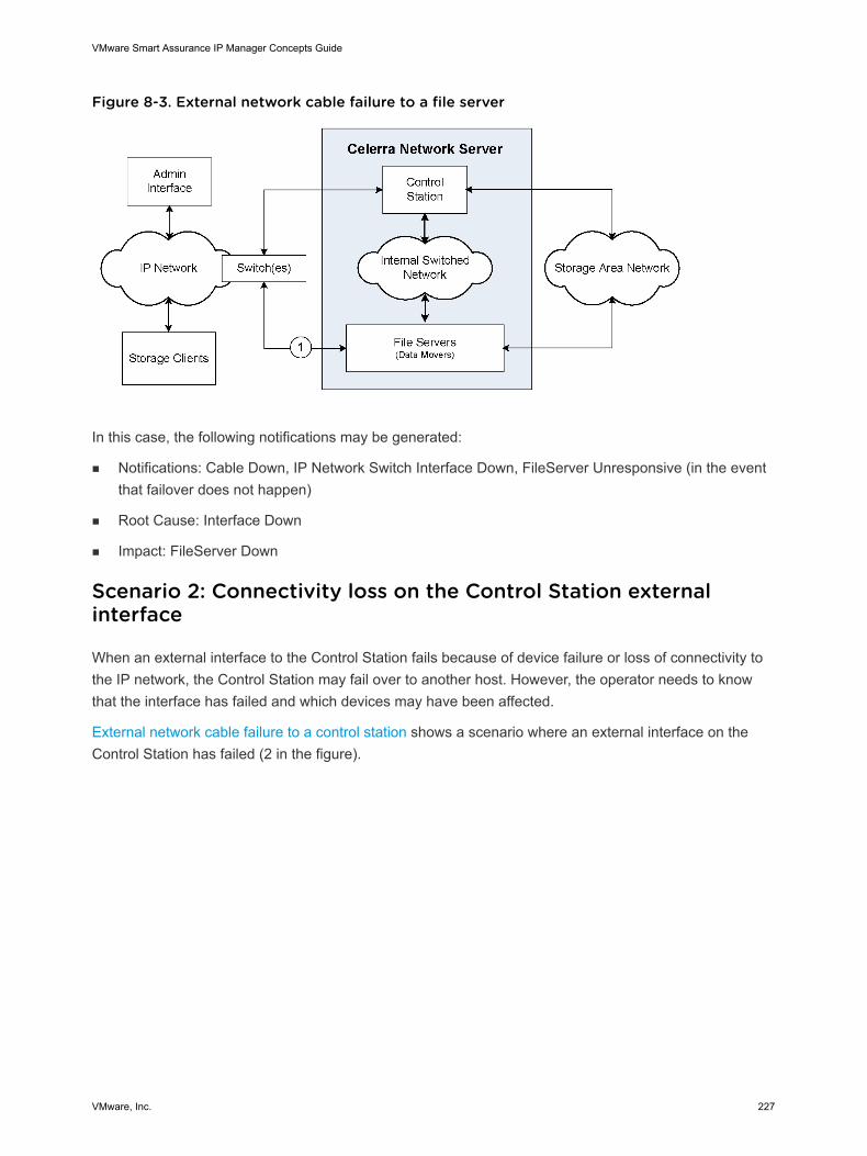
Figure 8-3. External network cable failure to a file server
In this case, the following notifications may be generated:
n Notifications: Cable Down, IP Network Switch Interface Down, FileServer Unresponsive (in the eventthat failover does not happen)
n Root Cause: Interface Down
n Impact: FileServer Down
Scenario 2: Connectivity loss on the Control Station externalinterface
When an external interface to the Control Station fails because of device failure or loss of connectivity tothe IP network, the Control Station may fail over to another host. However, the operator needs to knowthat the interface has failed and which devices may have been affected.
External network cable failure to a control station shows a scenario where an external interface on theControl Station has failed (2 in the figure).
VMware Smart Assurance IP Manager Concepts Guide
VMware, Inc. 227
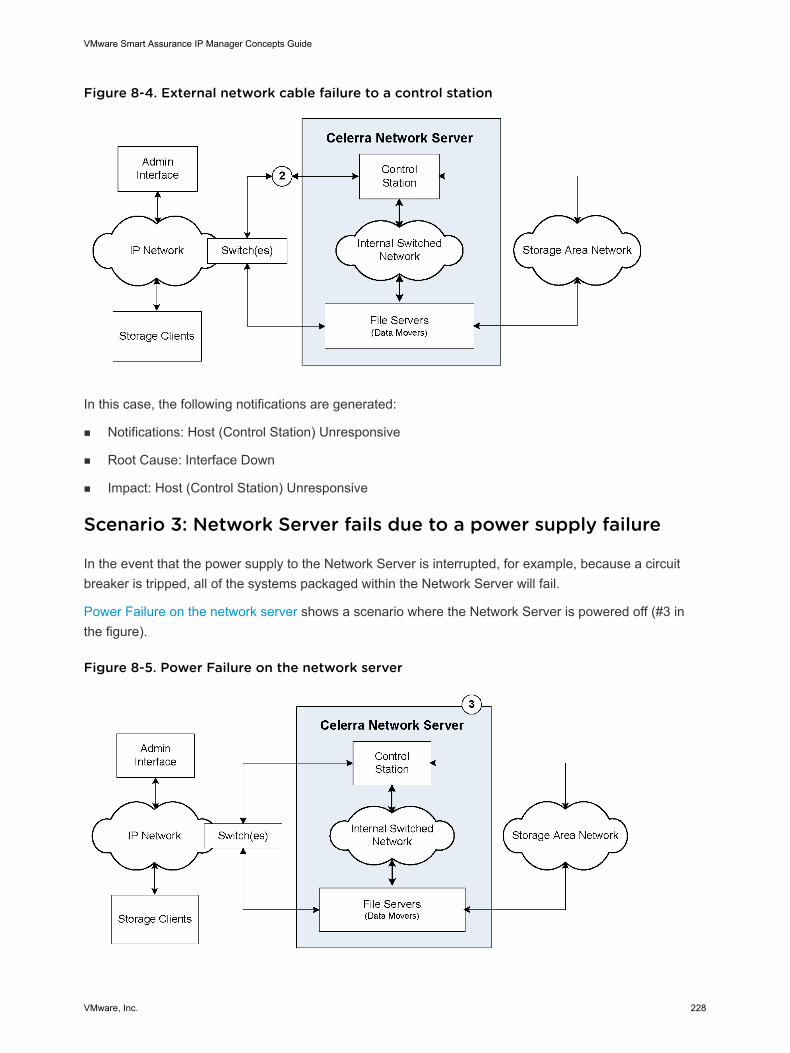
Figure 8-4. External network cable failure to a control station
In this case, the following notifications are generated:
n Notifications: Host (Control Station) Unresponsive
n Root Cause: Interface Down
n Impact: Host (Control Station) Unresponsive
Scenario 3: Network Server fails due to a power supply failure
In the event that the power supply to the Network Server is interrupted, for example, because a circuitbreaker is tripped, all of the systems packaged within the Network Server will fail.
Power Failure on the network server shows a scenario where the Network Server is powered off (#3 inthe figure).
Figure 8-5. Power Failure on the network server
VMware Smart Assurance IP Manager Concepts Guide
VMware, Inc. 228
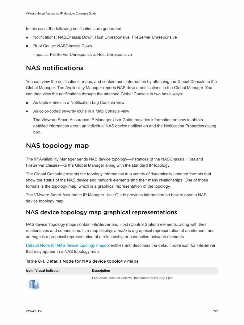
In this case, the following notifications are generated:
n Notifications: NASChassis Down, Host Unresponsive, FileServer Unresponsive
n Root Cause: NASChassis Down
Impacts: FileServer Unresponsive, Host Unresponsive
NAS notifications
You can view the notifications, maps, and containment information by attaching the Global Console to theGlobal Manager. The Availability Manager reports NAS device notifications to the Global Manager. Youcan then view the notifications through the attached Global Console in two basic ways:
n As table entries in a Notification Log Console view
n As color-coded severity icons in a Map Console view
The VMware Smart Assurance IP Manager User Guide provides information on how to obtaindetailed information about an individual NAS device notification and the Notification Properties dialogbox.
NAS topology map
The IP Availability Manager sends NAS device topology—instances of the NASChassis, Host andFileServer classes—to the Global Manager along with the standard IP topology.
The Global Console presents the topology information in a variety of dynamically updated formats thatshow the status of the NAS device and network elements and their many relationships. One of thoseformats is the topology map, which is a graphical representation of the topology.
The VMware Smart Assurance IP Manager User Guide provides information on how to open a NASdevice topology map.
NAS device topology map graphical representations
NAS device Topology maps contain FileServer and Host (Control Station) elements, along with theirrelationships and connections. In a map display, a node is a graphical representation of an element, andan edge is a graphical representation of a relationship or connection between elements.
Default Node for NAS device topology maps identifies and describes the default node icon for FileServerthat may appear in a NAS topology map.
Table 8-1. Default Node for NAS device topology maps
Icon / Visual indicator Description
FileServer, such as Celerra Data Mover or NetApp Filer
VMware Smart Assurance IP Manager Concepts Guide
VMware, Inc. 229
You can replace the standard map nodes with other map nodes that are preferred by your organization.For detailed information about maps, refer to the VMware Smart Assurance Service Assurance ManagerOperator Guide.
NAS Connectivity Map
The NAS Connectivity map shows logical connectivity between NAS FileServer elements and NAS Hostelements. No physical connectivity details are included in this map. See #unique_453/unique_453_Connect_42__IP_CONCEPTS_NAS_38378 for an example.
The initial layout of a NAS Connectivity map depends on the element that you select to launch the map.The edge marked with a + (plus) sign indicates that the edge can be expanded to show hiddenMountPoints.
Selecting a NAS element results in an initial layout that centers around the selected element (also knownas the map’s focal object) and shows the relationships to all elements within one hop of the selectedelement. Expanding the expandable nodes and edges reveals additional relationships and elements andeventually ends in a fully expanded map.
NAS device map types
The following Availability Manager map types show NAS devices.
n Physical Connectivity
n IP Network Connectivity
n NAS Connectivity
n SAN Connectivity
Physical connectivity map with a NAS FileServer shows a Physical Connectivity map for a NASFileServer. In this map, the FileServer (123DM2NFS, a Celerra Data Mover) is displayed with a majoralert.
VMware Smart Assurance IP Manager Concepts Guide
VMware, Inc. 230
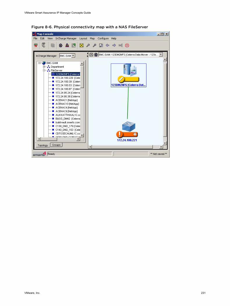
Figure 8-6. Physical connectivity map with a NAS FileServer
VMware Smart Assurance IP Manager Concepts Guide
VMware, Inc. 231
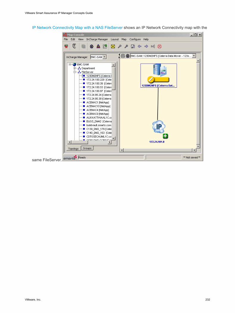
IP Network Connectivity Map with a NAS FileServer shows an IP Network Connectivity map with the
same FileServer.
VMware Smart Assurance IP Manager Concepts Guide
VMware, Inc. 232
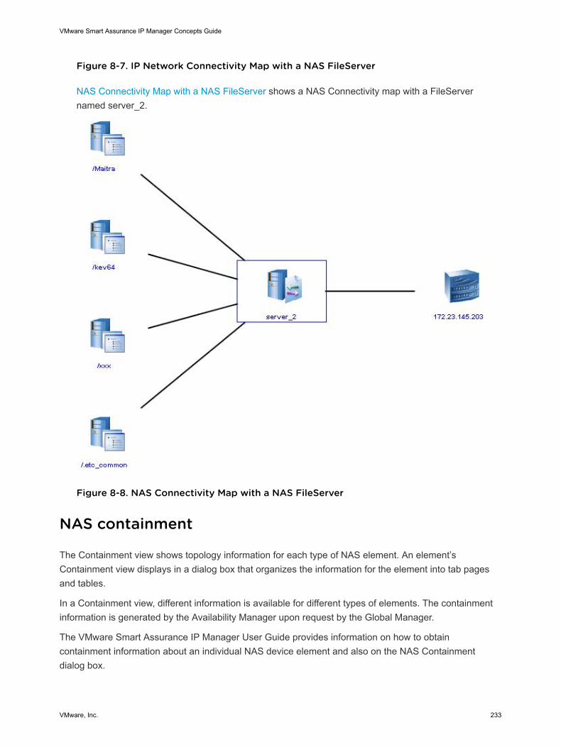
Figure 8-7. IP Network Connectivity Map with a NAS FileServer
NAS Connectivity Map with a NAS FileServer shows a NAS Connectivity map with a FileServernamed server_2.
Figure 8-8. NAS Connectivity Map with a NAS FileServer
NAS containment
The Containment view shows topology information for each type of NAS element. An element’sContainment view displays in a dialog box that organizes the information for the element into tab pagesand tables.
In a Containment view, different information is available for different types of elements. The containmentinformation is generated by the Availability Manager upon request by the Global Manager.
The VMware Smart Assurance IP Manager User Guide provides information on how to obtaincontainment information about an individual NAS device element and also on the NAS Containmentdialog box.
VMware Smart Assurance IP Manager Concepts Guide
VMware, Inc. 233
Terminology 9This section describes common terms used in the IP Manager.
This chapter includes the following topics:
n System and device
n Modeled topology
n Object
n Domain Manager
n Satellite Domain Manager
n Device connection
n Discovery
n Map Console
n NASChassis Element
n Edge (Map Console display component)
n IP Availability Manager
n IP Performance Manager
n Event
n Icon (Map Console display component)
n IP Manager
n Global Manager
n Notification
n Notification Log
n Repository
n Global Console
n Impact Analysis
n Logical link
n Partition
n Managed Element
VMware, Inc. 234
n Root-Cause Analysis
n Topology Browser
n Adapter
n FileServer Element
n Certification
n Certification Matrix
n Codebook
n Correlation Model
n Correlator
n Broker
n Containment
n ICMP
n ICMP operation
n SNMP
n SNMP key components
n SNMP basic operations
n SNMP versions
n SNMPv1, SNMPv2c, and SNMPv3 security
n NASChassis
n FileServer
n Comparable terms
n Wildcard patterns
System and device
The term system, as used in this document, is a generic term representing a computer-based networkentity, such as a switch, router, hub, bridge, or host. The term device, as used in this document, hasessentially the same meaning as system except that device also conveys a sense of specific model, suchas a specific model of switch, router, hub, bridge, or host.
Modeled topology
VMware Smart Assurance IP Manager Concepts Guide
VMware, Inc. 235
IP Availability Manager uses VMware Smart Assurance ICIM class models to create (within its repository)instances of the managed network systems (switches, routers, hubs, bridges, and hosts), theirdependencies, their internal components, and their connections. The modeled topology mirrors the realtopology in the managed network.
Object
The term “object” has a dual meaning: It simultaneously represents both:
n An VMware Smart Assurance object in the modeled topology.
n A physical or logical entity in the real topology. An VMware Smart Assurance object corresponds to aphysical or logical entity in the real topology.
Domain Manager
A Domain Manager is a service assurance application that is associated with a particular type ofinformation technology domain, such as networks, systems, applications, or application services. For IPManager, the domain is IP network transport. A Domain Manager includes a Repository of the managedtopology and a problem correlation model that monitors network elements, uses correlation technology topinpoint the root causes of failures, and diagnoses the effects of failures on related elements. DomainManagers report results to the Global Manager for consolidation, and display through the Global Console.
Each Domain Manager is autonomous in the sense that it:
n Maintains its own data models, repository, and problem signatures.
n Monitors and analyzes the discovered objects in its own domain.
VMware Smart Assurance IP Manager represents four VMware Smart Assurance Domain Managers:
n VMware Smart Assurance IP Availability Manager
n VMware Smart Assurance IP Performance Manager
n VMware Smart Assurance IP Server Performance Manager
n VMware Smart Assurance IP Availability Manager Extension for NAS
IP Availability Manager and IP Performance Manager are examples of VMware Smart AssuranceDomain Managers. You can choose to start IP Availability Manager (AM) only, IP PerformanceManager (PM) only or a combination of both IP Availability Manager and IP Performance Manager(AM-PM).
The VMware Smart Assurance Installation Guide for SAM, IP, ESM, MPLS, and NPM Managersprovides the procedure to install services manually for the underlying servers used in the IPManagement Suite.
Satellite Domain Manager
VMware Smart Assurance IP Manager Concepts Guide
VMware, Inc. 236
A satellite Domain Manager refers to any of the VMware Smart Assurance Domain Managers that importtopology, CLI device-access objects (if needed), and status updates from the IP Availability Manager.
Satellite Domain Managers include:
n MPLS Manager
n Multicast Manager
n Network Protocol Manager for BGP
n Network Protocol Manager for EIGRP
n Network Protocol Manager for IS-IS
n Network Protocol Manager for OSPF VoIP Availability Manager
n VMware Smart Assurance VoIP Availability Manager
IP Availability Manager Extension for NAS supplies additional event information to Storage Insight forAvailability.
Note A feature license controls whether IP Availability Manager Extension for NAS software isavailable for configuration. With this extension, IP Availability Manager can discover and monitorVMware Celerra®® NAS gateways and diagnose network-attached storage (NAS) connectivityproblems.
Device connection
A device connection is a link between two network adapters. IP Availability Manager performsconnectivity analysis on the following device connection object types:
n Cable — A connection between a port and an interface. For example, a cable connects a port on aswitch to an interface on a router.
n TrunkCable — A connection between two ports. Switches are often trunked to connect multiplesegments or to provide redundant pathways through the network.
n NetworkConnection — A connection between two interfaces. A network connection can be a logicalconnection or a physical connection. An example of a logical connection is when routers areconnected through a virtual circuit and none of the intermediate network devices are included in thetopology. An example of a physical connection is when routers are connected through a serial orpoint-to-point connection.
Discovery
VMware Smart Assurance IP Manager Concepts Guide
VMware, Inc. 237
VMware Smart Assurance discovery is the process of using VMware Smart Assurance object classmodels to create a representation of the managed topology within the repository, or database, of aDomain Manager. For the IP Manager, data is collected from the managed topology to create instancesof the managed network systems, their relationships, their internal components, and their logicalconnections.
When a system is added to the managed network environment, the IP Manager performs discovery todetermine the system’s configuration and its relationships to other managed systems and components.When a system is removed from the managed network environment and deleted from the topology, the IPManager removes the system and all of its components from the modeled topology.
Systems can be added to or deleted from the modeled topology at any time. Adding new systems doesnot impede the ability of the IP Manager to monitor systems that are already managed.
Map Console
In the Global Console, the Map Console displays graphical representations of physical and logicaltopologies including display of managed element icons and edges (connections between elements).Network topology maps for NAS devices include:
n Physical Connectivity Map
n IP Network Connectivity Map
NASChassis Element
In the VMware Smart Assurance model for the NAS Extension, the class that represents the CelerraNetwork Server.
In the Global Console for the NAS Extension, a NASChassis is a representation of a Celerra NetworkServer, which is the cabinet that contains NAS system elements including a Control Station, Data Movers,and other components that are not monitored by VMware Smart Assurance.
Edge (Map Console display component)
In a map view, an edge represents a connection between two elements. Note that a map edge is not tobe confused with a device such as an edge router.
IP Availability Manager
VMware Smart Assurance IP Manager Concepts Guide
VMware, Inc. 238
VMware Smart Assurance IP Availability Manager is an example of an VMware Smart Assurance DomainManager, where a Domain Manager is a service-assurance application associated with a particular typeof information-technology domain (networks, systems, applications, and network application services).For IP Availability Manager, the domain is IP network transport connectivity. Each Domain Manager isautonomous in the sense that it maintains its own data models, repository, and problem signatures, andmonitors and analyzes the discovered objects in its own domain.
IP Performance Manager
VMware Smart Assurance IP Performance Manager is an VMware Smart Assurance Domain Manager,where a Domain Manager is a service-assurance application associated with a particular type ofinformation-technology domain (networks, systems, applications, application services). For IPPerformance Manager, the domain is IP network transport performance. Each Domain Manager isautonomous in the sense that it maintains its own data models, repository, and problem signatures, andmonitors and analyzes the discovered objects in its own domain.
IP Server Performance Manager is an enhanced version of IP Performance Manager and is availablethrough a feature license. In addition to the standard capabilities of IP Performance Manager, IP ServerPerformance Manager can also discover and monitor host disks, host filesystems, and additionalinformation about host processors and memory.
Event
A notable condition that occurs in a network device. The condition may be identified by a message sentfrom the network element, by a management station polling the element, or by an adapter or third-partysoftware. A Domain Manager uses events, alerts, and other data to perform root-cause and impactanalysis.
Icon (Map Console display component)
In a map view for the NAS Extension, an icon represents an entity such as a FileServer or Host element.In the map view, icons are connected by edges.
IP Manager
The IP Manager discovers Layer 2 and Layer 3 connectivity in multivendor, switched, and routednetworks. It monitors and analyzes network connectivity and performance, and exports network topology,problems, and events to the VMware Smart Assurance Service Assurance Manager (Global Manager).
Global Manager
VMware Smart Assurance IP Manager Concepts Guide
VMware, Inc. 239
The Global Manager integrates the topology, problem, and event information that is imported from the IPManager component servers and the satellite Domain Managers, and relates the information to servicesand customers. It also provides cross-domain and end-to-end impact analysis.
The Global Manager displays the topology, problem, and event information through the Global Console.
Notification
In the Notification Log of the Global Console, an VMware Smart Assurance message, issued by aDomain Manager, that indicates a problem or other significant event.
Notification Log
In the Global Console, a listing of current notifications, including comprehensive information about theelement involved, impact on other elements, root-cause indication, severity, acknowledgment status,escalation information, and so on.
Repository
The VMware Smart Assurance in-memory, object-oriented data structure that stores information about themanaged elements currently in a network, and the relationships between the elements.
Global Console
The Global Console provides a graphical user interface for configuration and administration of GlobalManager, Adapter Platforms, Domain Managers, and externally running VMware Smart Assuranceadapters, such as the SNMP Trap Adapter.
When the Global Console is attached to the Global Manager, you can browse the topology in variousforms, including maps, and to view notifications about problems that impact availability and performance.
Impact Analysis
The process of analyzing the effect that root-cause problems have on other elements in the managedsystem. Impact analysis is performed by Domain Managers, such as the Availability Manager.
Logical link
A logical link models the path that connects service access points to each other. IP Availability Managerperforms connectivity analysis on the following logical link object types:
IP Network - A logical link that allows any two IPv4 addresses that are “ConnectedVia” the IPv4Networkto communicate with one another.
VMware Smart Assurance IP Manager Concepts Guide
VMware, Inc. 240
IPv6Network — A logical link that allows any two IPv6 addresses that are “ConnectedVia” theIPv6Network to communicate with one another.
VLAN — A logical link that allows any two ports (or MAC addresses) that are “PartOf” the VLAN tocommunicate with one another.
Partition
A partition is a group of managed devices formed by IP Availability Manager to help in root-causeanalysis. IP Availability Manager builds a topology that describes managed devices in your network andtheir interconnections. If a device is modeled in the topology, there must be a path in the actual networkthat connects the device to the management station. Ideally, IP Availability Manager can also haverepresentations of all the devices on that path.
However, some devices along the path might not actually be represented in your network topology. Forexample, those devices might not have SNMPAgents, or IP Availability Manager might not have access totheir SNMPAgents, or access to the agents might be blocked by a firewall or some other administrativemechanism. Also, if you do not use autodiscovery, your seed file or information obtained from anotherNetwork Management System (NMS) might be incomplete. Or, you might have explicitly unmanaged ordeleted some of the devices which are on that path.
IP Availability Manager's root-cause analysis algorithms need to determine the connectivity amongmanaged devices. When the topology is incomplete, IP Availability Manager creates partitions to group allthe related managed devices, which helps analysis to proceed.
Within a single partition, any two managed devices are indeed connected by a path. However, objectswithin distinct partitions have no path between them in the modeled topology, even though they areconnected in the actual network.
Because many configurations produce large numbers of apparently isolated objects, usually hosts, IPAvailability Manager only creates partitions with two or more devices.
You can assign names to the partitions in your network using the partition.conf file. The VMware SmartAssurance IP Manager User Guide provides more information about naming partitions.
Managed Element
An instance of a physical or logical network element that is monitored by a Domain Manager.
Root-Cause Analysis
The process of analyzing the cause and effect relationships among alarms, alerts, and events in complexsystems in order to determine the authentic problem. Root-cause analysis is performed by DomainManagers.
VMware Smart Assurance IP Manager Concepts Guide
VMware, Inc. 241
Topology Browser
In the Global Console, the Topology Browser provides a complete inventory (actual and inrepresentational form) of managed elements in the Repository of a Domain Manager, and theinterconnections between those elements. The Topology Browser displays the topology in hierarchicalform arranged by classes and instances.
Adapter
A program that integrates an VMware Smart Assurance Manager with external components. For the NASExtension, an HTTPS Adapter queries the Celerra Control Station for internal topology information.
FileServer Element
In the VMware Smart Assurance model for the NAS Extension, the class that represents Data Moversand Filers. In the Global Console for the NAS Extension, a FileServer element is a representation of aCelerra Data Mover or NetApp Filer.
Certification
A label assigned to a network element (system, device, service or application) during the discoveryprocess. The label is based on information that is contained in the oid2type*.conf files. Labels include:
CERTIFIED---Indicates that the element is discovered using standard mib-2 data and proprietary MIBs.
TEMPLATE---Indicates that the OID is recognized by a new entry in oid2type*.conf. Note thatoid2type*.conf is a user-modifiable file with no default entries.
Certification Matrix
Listing of devices that VMware Smart Assurance certifies for management by an VMware SmartAssurance Manager.
Codebook
An VMware Smart Assurance data structure that associates problems with the symptoms they cause.This information is used for root-cause and impact analysis using the VMware Smart Assurance patentedCodebook Correlation Technology.
Correlation Model
VMware Smart Assurance IP Manager Concepts Guide
VMware, Inc. 242
An object-oriented data model that describes the properties of an element, including the characteristicproblems of the element, problem symptoms, and symptom propagation patterns to related elements.
Correlator
A general-purpose correlation analysis engine that performs filtering and model processing, along withroot-cause and effects analysis. It is driven by three inputs: problem models, topology, and real-time dataand events.
Broker
The VMware Smart Assurance Broker facilitates Global Console connections to the componentapplications in an VMware Smart Assurance system deployment.
When you start a Global Console process, the process connects to the Broker and launches a dialog boxthrough which the user views and selects any component application that is registered with the Broker.After the user selects an application, the Global Console connects to the application and disconnectsfrom the Broker. The Broker can support IPv4 and IPv6 protocols. If the component applications in yourdeployment are identified by IPv4 and IPv6 addresses, the Broker must reside on a dual-stack host sothat it has both an IPv4 address and an IPv6 address. If all component applications in your deploymentuse the same IP protocol version, the Broker must reside on a host with an IP address that accepts thatprotocol version.
Containment
The Containment dialog box provides detailed information about a managed element. Containmentinformation varies depending upon the type of element and the type of analysis being performed by theunderlying domain. As examples, for a network connection, the containment information includes detailsabout connection points; for a device managed by IP Performance Manager, containment informationincludes details about the device’s memory. The Containment dialog box is available for selectednotifications in the Notification Log Console, for selected instances in the Topology Browser Console, andfor selected nodes in the Map Console. When an element is managed by multiple Domain Managers, theContainment dialog box includes all the containment information for each domain.
ICMP
Internet Control Message Protocol is tightly integrated with IP. ICMP messages, which are delivered in IPpackets, are used for out-of-band messages that are related to network operation. Some of ICMP’sfunctions are to announce network errors, to announce network congestion, to announce timeouts, and toassist in troubleshooting network problems.
VMware Smart Assurance IP Manager Concepts Guide
VMware, Inc. 243
ICMP supports an Echo function that sends a packet on a round-trip between two hosts. Ping, which is acommon network management tool that is based on the Echo function, transmits a series of packets tomeasure average round-trip times and to compute loss percentages. Ping is central to the IP ManagerICMP polling.
The IP Manager supports both IPv4 ICMP polling and IPv6 ICMP polling. An IPv4 ICMP poller sendsICMP messages for use with IP version 4. An IPv6 ICMP poller sends ICMP messages for use with IPversion 6. All IP Manager products support IPv4 and IPv6 ICMP polling.
ICMP operation
The IP Manager uses ICMP polling for two purposes:
n To determine whether a system is reachable
n To monitor a system after the system has been discovered
SNMP
The Simple Network Management Protocol is used by network management applications for discovery,fault management, and performance management. SNMP is an application-layer protocol that exchangesmanagement information between a network management application, such as the IP Manager, and oneor more managed network objects, called agents.
SNMP, itself, does not provide network management. What SNMP does provide is a framework, orinfrastructure, on which network management applications can be built.
In this document, unless otherwise noted, SNMP works in conjunction with both IPv4 and IPv6 protocols.
SNMP key components
SNMP key components are the management station, agent, management information base, and theSNMP protocol. Each SNMP agent or SNMP manager maintains a MIB. An agent MIB containsinformation about the network system managed by the SNMP agent, and about the agent itself. Amanager MIB contains network management information that is extracted by the SNMP manager fromeach agent MIB.
SNMP basic operations
SNMP includes the following basic operations:
n GET
n SET
n NOTIFY
n INFORM
VMware Smart Assurance IP Manager Concepts Guide
VMware, Inc. 244
SNMP versions
Currently, there are three versions of the SNMP protocol: v1, v2c, and v3. SNMPv1 and v2c offerrudimentary authentication and authorization schemes, whereas SNMPv3 offers robust authenticationand authorization schemes plus data privacy.
SNMPv1, SNMPv2c, and SNMPv3 security
SNMPv1 security consists of a pairing of an SNMP agent with some arbitrary set of SNMP managers toform an SNMP community. Each SNMP community is given a name called the community name orcommunity string for the community. Common community names are public (read-only), private (read-write), and trap. The permissions (read-only, read-write) for a community name indicate the read-writepermissions of an SNMP manager when using that community name to access an agent’s MIB.Community names can be thought of as passwords to SNMPv1 agents.
Like SNMPv1, SNMPv2c uses the notion of communities to establish trust between SNMP managers andSNMP agents. Unlike SNMPv1, SNMPv2c uses an updated version of the structure of managementinformation (SMI), which extends the MIB object tree, allows several new data types, and makes anumber of other changes. SNMPv2c is more efficient than SNMPv1 and has better error-handlingcapabilities.
SNMPv3 provides integrity, authenticity, data privacy, and access control for SNMP messages exchangedbetween an SNMP manager and the managed SNMP agents. Unlike the community-based administrativemodel of SNMPv1 and V2C, SNMPv3 unambiguously identifies the source and destination of each SNMPmessage. And instead of using community names to establish trust between SNMP managers and SNMPagents, SNMPv3 uses the following security-related services to establish trust:
n Authentication
The source includes information in each sent message that identifies the source as authentic, andperforms the required functions to ensure message integrity. A typical authentication scheme requiresthat the source and destination parties share the same authentication key.
n Privacy
Messages are encrypted to achieve privacy. The encryption is done in such a way that only theintended destination can perform the decryption. A typical privacy scheme requires that the sourceand destination parties share the same privacy key.
n Access control
Both the source and destination play a part in access control. Each destination may have a distinctaccess policy for each potential source, which gives an administrator considerable flexibility in settingup an SNMP management system and assigning various levels of authorization to different users.
NASChassis
VMware Smart Assurance IP Manager Concepts Guide
VMware, Inc. 245
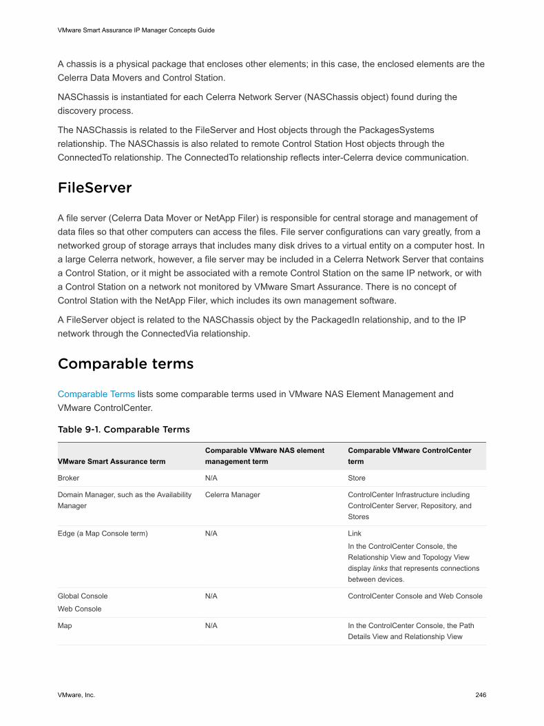
A chassis is a physical package that encloses other elements; in this case, the enclosed elements are theCelerra Data Movers and Control Station.
NASChassis is instantiated for each Celerra Network Server (NASChassis object) found during thediscovery process.
The NASChassis is related to the FileServer and Host objects through the PackagesSystemsrelationship. The NASChassis is also related to remote Control Station Host objects through theConnectedTo relationship. The ConnectedTo relationship reflects inter-Celerra device communication.
FileServer
A file server (Celerra Data Mover or NetApp Filer) is responsible for central storage and management ofdata files so that other computers can access the files. File server configurations can vary greatly, from anetworked group of storage arrays that includes many disk drives to a virtual entity on a computer host. Ina large Celerra network, however, a file server may be included in a Celerra Network Server that containsa Control Station, or it might be associated with a remote Control Station on the same IP network, or witha Control Station on a network not monitored by VMware Smart Assurance. There is no concept ofControl Station with the NetApp Filer, which includes its own management software.
A FileServer object is related to the NASChassis object by the PackagedIn relationship, and to the IPnetwork through the ConnectedVia relationship.
Comparable terms
Comparable Terms lists some comparable terms used in VMware NAS Element Management andVMware ControlCenter.
Table 9-1. Comparable Terms
VMware Smart Assurance termComparable VMware NAS elementmanagement term
Comparable VMware ControlCenterterm
Broker N/A Store
Domain Manager, such as the AvailabilityManager
Celerra Manager ControlCenter Infrastructure includingControlCenter Server, Repository, andStores
Edge (a Map Console term) N/A Link
In the ControlCenter Console, theRelationship View and Topology Viewdisplay links that represents connectionsbetween devices.
Global Console
Web Console
N/A ControlCenter Console and Web Console
Map N/A In the ControlCenter Console, the PathDetails View and Relationship View
VMware Smart Assurance IP Manager Concepts Guide
VMware, Inc. 246
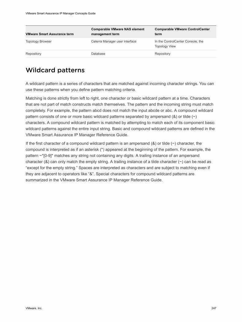
VMware Smart Assurance termComparable VMware NAS elementmanagement term
Comparable VMware ControlCenterterm
Topology Browser Celerra Manager user interface In the ControlCenter Console, theTopology View
Repository Database Repository
Wildcard patterns
A wildcard pattern is a series of characters that are matched against incoming character strings. You canuse these patterns when you define pattern matching criteria.
Matching is done strictly from left to right, one character or basic wildcard pattern at a time. Charactersthat are not part of match constructs match themselves. The pattern and the incoming string must matchcompletely. For example, the pattern abcd does not match the input abcde or abc. A compound wildcardpattern consists of one or more basic wildcard patterns separated by ampersand (&) or tilde (~)characters. A compound wildcard pattern is matched by attempting to match each of its component basicwildcard patterns against the entire input string. Basic and compound wildcard patterns are defined in theVMware Smart Assurance IP Manager Reference Guide.
If the first character of a compound wildcard pattern is an ampersand (&) or tilde (~) character, thecompound is interpreted as if an asterisk (*) appeared at the beginning of the pattern. For example, thepattern ~*[0-9]* matches any string not containing any digits. A trailing instance of an ampersandcharacter (&) can only match the empty string. A trailing instance of a tilde character (~) can be read as“except for the empty string.” Spaces are interpreted as characters and are subject to matching even ifthey are adjacent to operators like “&”. Special characters for compound wildcard patterns aresummarized in the VMware Smart Assurance IP Manager Reference Guide.
VMware Smart Assurance IP Manager Concepts Guide
VMware, Inc. 247

![Artificial Intelligence Based Model for Channel Status ...on the radio parameters. The CE [38] consists of user interface, sensor interface, radio interface, scheduler and cognitive](https://img.pdfslide.net/doc/110x75/5e7afceb548f30113a4e8f86/artificial-intelligence-based-model-for-channel-status-on-the-radio-parameters.jpg)