Embed Size (px)
Citation preview
Oracle® Communications SessionBorder Controller and SessionRouterVNF Essentials Guide
Release S-CZ7.3.9March 2018

Oracle Communications Session Border Controller and Session Router VNF Essentials Guide, Release S-CZ7.3.9
Copyright © 2014, 2017, Oracle and/or its affiliates. All rights reserved.
This software and related documentation are provided under a license agreement containing restrictions on use anddisclosure and are protected by intellectual property laws. Except as expressly permitted in your license agreement orallowed by law, you may not use, copy, reproduce, translate, broadcast, modify, license, transmit, distribute, exhibit,perform, publish, or display any part, in any form, or by any means. Reverse engineering, disassembly, or decompilationof this software, unless required by law for interoperability, is prohibited.
The information contained herein is subject to change without notice and is not warranted to be error-free. If you findany errors, please report them to us in writing.
If this is software or related documentation that is delivered to the U.S. Government or anyone licensing it on behalf ofthe U.S. Government, then the following notice is applicable:
U.S. GOVERNMENT END USERS: Oracle programs, including any operating system, integrated software, anyprograms installed on the hardware, and/or documentation, delivered to U.S. Government end users are "commercialcomputer software" pursuant to the applicable Federal Acquisition Regulation and agency-specific supplementalregulations. As such, use, duplication, disclosure, modification, and adaptation of the programs, including any operatingsystem, integrated software, any programs installed on the hardware, and/or documentation, shall be subject to licenseterms and license restrictions applicable to the programs. No other rights are granted to the U.S. Government.
This software or hardware is developed for general use in a variety of information management applications. It is notdeveloped or intended for use in any inherently dangerous applications, including applications that may create a risk ofpersonal injury. If you use this software or hardware in dangerous applications, then you shall be responsible to take allappropriate fail-safe, backup, redundancy, and other measures to ensure its safe use. Oracle Corporation and its affiliatesdisclaim any liability for any damages caused by use of this software or hardware in dangerous applications.
Oracle and Java are registered trademarks of Oracle and/or its affiliates. Other names may be trademarks of theirrespective owners.
Intel and Intel Xeon are trademarks or registered trademarks of Intel Corporation. All SPARC trademarks are used underlicense and are trademarks or registered trademarks of SPARC International, Inc. AMD, Opteron, the AMD logo, andthe AMD Opteron logo are trademarks or registered trademarks of Advanced Micro Devices. UNIX is a registeredtrademark of The Open Group.
This software or hardware and documentation may provide access to or information about content, products, andservices from third parties. Oracle Corporation and its affiliates are not responsible for and expressly disclaim allwarranties of any kind with respect to third-party content, products, and services unless otherwise set forth in anapplicable agreement between you and Oracle. Oracle Corporation and its affiliates will not be responsible for any loss,costs, or damages incurred due to your access to or use of third-party content, products, or services, except as set forth inan applicable agreement between you and Oracle.
Contents
About this Guide
1 The Oracle Communications SBC and SR as VNFs
Qualified Hypervisors, Hardware and I/O Modes 1-1Virtual Machine Platform Resources 1-2Hyper-threading and CPU Affinity 1-3Host Hypervisor CPU Pinning 1-3Distribution Components 1-3Configuration Overview 1-4Co-Product Support 1-5Transcoding Support 1-5VLAN Support 1-5Provisioning Entitlements 1-6SPL and Baseline Information 1-6
2 Network Functions Virtualization Overview
3 Introduction to Platform Preparation and Software Deployment
Virtual Machines 3-1
4 Virtual Machine Platforms
Create and Deploy on Oracle VM Manager 4-1Create and Deploy on KVM 4-3Create and Deploy on VMware® 4-5
5 Configuring Your Device for NFV
Media Manager Configuration 5-1Core Configuration 5-2
iii
Virtual MAC Addresses for VNFs 5-4System Shutdown 5-4
6 Boot Management
Boot Parameters 6-1Boot Parameter Definitions 6-2
Changing Boot Parameters 6-3Change Boot Parameters from the ACLI 6-3Change Boot Parameters by Interrupting a Boot in Progress 6-4
7 Formatting Disks for VM Deployments
Formatting Procedure for VM Deployments 7-1
8 VM Interfaces
The MACTAB File 8-1Working with the MACTAB File 8-2Serial Interfaces 8-2
9 References and Debugging
Packet Trace Over Systems using DPDK 9-1Starting a Local Packet Trace on Systems Running DPDK 9-2Stopping a Local Packet Trace on Systems Running DPDK 9-2
SNMP MIBs and Traps 9-3apUsbcSysDPDKObjects 9-3apUsbcSysScalingObjects 9-4
Show Commands 9-4show datapath-config 9-4show platform limits 9-5
Supporting Configuration 9-6Log Files for the VNF 9-6
A Known Issues and Caveats
Known Issues A-1Caveats A-2
iv

B DPDK-Based OVS Installation
v

List of Figures
4-1 Properties Dialog for OVF Deployment 4-6
4-2 OVF Deployment Status Dialog 4-7
vi
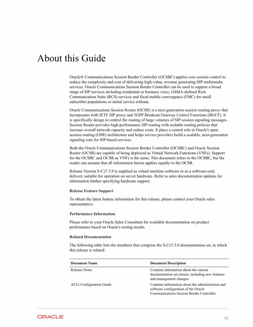
About this Guide
Oracle® Communications Session Border Controller (OCSBC) applies core session control toreduce the complexity and cost of delivering high-value, revenue generating SIP multimediaservices. Oracle Communications Session Border Controller can be used to support a broadrange of SIP services including residential or business voice, GSMA-defined RichCommunication Suite (RCS) services and fixed mobile convergence (FMC) for smallsubscriber populations or initial service rollouts.
Oracle Communications Session Router (OCSR) is a next generation session routing proxy thatincorporates both IETF SIP proxy and 3GPP Breakout Gateway Control Functions (BGCF). Itis specifically design to control the routing of large volumes of SIP session signaling messages.Session Router provides high-performance SIP routing with scalable routing policies thatincrease overall network capacity and reduce costs. It plays a central role in Oracle's opensession routing (OSR) architecture and helps service providers build a scalable, next-generationsignaling core for SIP-based services.
Both the Oracle Communications Session Border Controller (OCSBC) and Oracle SessionRouter (OCSR) are capable of being deployed as Virtual Network Functions (VNFs). Supportfor the OCSBC and OCSR as VNFs is the same. This document refers to the OCSBC, but thereader can assume that all information herein applies equally to the OCSR.
Release Version S-Cz7.3.9 is supplied as virtual machine software or as a software-onlydelivery suitable for operation on server hardware. Refer to sales documentation updates forinformation further specifying hardware support.
Release Feature Support
To obtain the latest feature information for this release, please contact your Oracle salesrepresentative.
Performance Information
Please refer to your Oracle Sales Consultant for available documentation on productperformance based on Oracle's testing results.
Related Documentation
The following table lists the members that comprise the S-Cz7.3.0 documentation set, to whichthis release is related:
Document Name Document Description
Release Notes Contains information about the currentdocumentation set release, including new featuresand management changes.
ACLI Configuration Guide Contains information about the administration andsoftware configuration of the OracleCommunications Session Border Controller.
vii
Document Name Document Description
ACLI Reference Guide Contains explanations of how to use the ACLI,with alphabetical listings and descriptions of allACLI commands and configuration parameters.
Maintenance and Troubleshooting Guide Contains information about logs, performanceannouncements, system management, inventorymanagement, upgrades, working withconfigurations, and managing backups andarchives.
MIB Reference Guide Contains information about ManagementInformation Base (MIBs), Acme Packet’senterprise MIBs, general trap information,including specific details about standard traps andenterprise traps, Simple Network ManagementProtocol (SNMP) GET query information(including standard and enterprise SNMP GETquery names, object identifier names and numbers,and descriptions), examples of scalar and tableobjects.
Accounting Guide Contains information about accounting support,including details about RADIUS and Rfaccounting.
HDR Resource Guide Contains information about the Historical DataRecording (HDR) feature. This guide includesHDR configuration and system-wide statisticalinformation.
Administrative Security Essentials Contains information about support for theAdministrative Security license.
Security Guide Contains information about security considerationsand best practices from a network and applicationsecurity perspective for the OracleCommunications Session Border Controller familyof products.
Training
Oracle offers extensive training on products via Oracle University. Find information on classes,curriculum and registration at http://education.oracle.com. Instructor-led, remote instructor, andself-directed classes are available, depending on the subject. Curriculum can include lectureand hands-on activities.
The Oracle SBC Configuration and Administration class provides an introduction to theSession Border Controller.
Support and Advanced Customer Services
Oracle provides access to product documentation, service request tools, and other relatedinformation via My Oracle Support. Oracle also offers expert Advanced Customer services onthis and all other products via My Oracle Support. Information about service offerings andprocurement is available at https://support.oracle.com.
Intended Audience
The information presented in this document is intended for Sales Engineers, SolutionArchitects, Implementation Engineers, and Support Technicians working on NFV
About this Guide
viii
environments. This document explains Oracle's solution and its configuration, meetingcustomer needs at a high level.
Revision History
Date Description
March 2017 • Initial ReleaseMarch 2017 • Removes incorrect reference to SLBMay 2017 • Corrects typo in 'About this Guide'
• Adds caveat on unsupported GUIJune 2017 • Removes IMS-AKA/RTP caveatDecember 2017 • Adds Upgrade Caveat about updating companion bootloader for p4+
upgradeMarch 2018 • Adds VMAC procedure for VNF HA
About this Guide
ix
1The Oracle Communications SBC and SR asVNFs
The OCSBC and OCSR are capable of being deployed as VNFs. Support for the OCSBC andOCSR as VNFs is the same. This document refers to the OCSBC, but the reader can assumethat the information applies equally to the OCSR.
VNF deployment types include:
• A standalone (not orchestrated) instance Oracle Communications Session BorderController operating as a virtual machine running on a hypervisor, and
• Virtual Machine(s) deployed within an Orchestrated Network Functions Virtualization(NFV) environment.
Standalone OCSBC VNF deployment instances are always supported. Support within anorchestrated environment is dependent on orchestrator and OCSBC version. High Availabilityconfigurations are supported by both deployment types.
Qualified Hypervisors, Hardware and I/O ModesFor version S-Cz7.3.9, Oracle has qualified the components listed in this section.
Oracle has qualified this version of the Oracle Communications Session Border Controller torun on the following hypervisors:
• XEN 4.4: Specifically using Oracle Virtual Machine (OVM) 3.4.2
• KVM: Using version embedded in Oracle Linux 7 with UEK4u1.Note the use of the following KVM component versions:
– Compiled against library: libvirt 2.0.0
– Using library: libvirt 2.0.0
– Using API: QEMU 2.0.0
– Running hypervisor: QEMU 1.5.3
• VMware: Using ESXI 6.0 u2 on VMware vCenter Server
Qualified hardware platforms include:
• Netra X5-2
• Oracle X5-2
Qualified interface chipsets include:
• Intel x540/82599
• Intel i350
• Intel X710 / XL710
Qualified interface I/O modes include:
1-1
• PV (VIF on XEN)
• SR-IOV
• PCI Passthrough
Virtual Machine Platform ResourcesAn OCSBC and OCSR virtual machine requires CPU core, memory, disk size, and networkinterfaces specified for operation. The system uses the Data Plane Development Kit (DPDK)for datapath design, which imposes VNF-specific resource requirements for CPU cores.Deployment details, such as the use of distributed DoS protection, specify resource utilizationbeyond the defaults.
The user configures CPU core utilization from the ACLI based on their deployment. The usercan also define memory and hard disk utilization based on deployment, but must configure thehypervisor with these settings prior to startup if they need them to be different then the machinedefaults setup by the machine template (OVA).
Default VM Resources
VM resource configuration defaults to the following:
• 4 CPU Cores - specific to deployment (See Core Configuration in this document)
• 8 GB RAM
• 40 GB hard disk (pre-formatted)
• 8 interfaces as follows:
– 1 for management (wancom0 )
– 2 for HA (wancom1 and 2)
– 1 spare
– 4 for media
Interface Host Mode
The Oracle Communications Session Border Controller S-CZ7.3.9 VNF supports interfacearchitectures using Hardware Virtualization Mode - Paravirtualized (HVM-PV):
• ESXi - No manual configuration required.
• KVM - HVM mode is enabled by default. Specifying PV as the interface type results inHVM plus PV.
• XEN (OVM) - The user must configure HVM+PV mode.
CPU Core Resources
The Oracle Communications Session Border Controller S-CZ7.3.9 VNF requires an Intel Core2processor or higher, or a fully emulated equivalent including 64-bit SSSE3 and TSC support.
If the hypervisor uses CPU emulation (qemu etc), Oracle recommends that the deploymentpasses the full set of host CPU features to the VM.
Chapter 1Virtual Machine Platform Resources
1-2
Hyper-threading and CPU AffinityDue to the polling operation of DPDK, using Hyper-threaded cores can degrade the OCSBCVNF's performance. Oracle recommends the user disable Hyper-threading in the host system ifpossible, or configure CPU affinities on the hypervisor to ensure mapping from only one virtualCPU to each physical CPU core.
The user can learn how to configure CPU affinity via their hypervisor documentation.
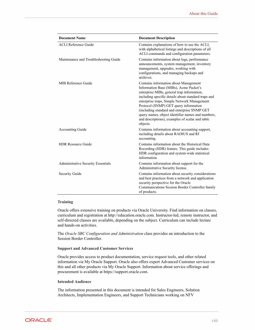
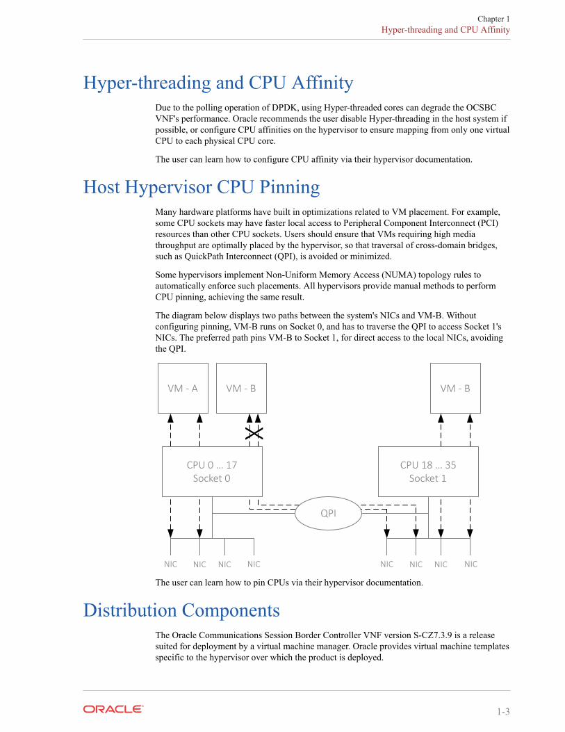
Host Hypervisor CPU PinningMany hardware platforms have built in optimizations related to VM placement. For example,some CPU sockets may have faster local access to Peripheral Component Interconnect (PCI)resources than other CPU sockets. Users should ensure that VMs requiring high mediathroughput are optimally placed by the hypervisor, so that traversal of cross-domain bridges,such as QuickPath Interconnect (QPI), is avoided or minimized.
Some hypervisors implement Non-Uniform Memory Access (NUMA) topology rules toautomatically enforce such placements. All hypervisors provide manual methods to performCPU pinning, achieving the same result.
The diagram below displays two paths between the system's NICs and VM-B. Withoutconfiguring pinning, VM-B runs on Socket 0, and has to traverse the QPI to access Socket 1'sNICs. The preferred path pins VM-B to Socket 1, for direct access to the local NICs, avoidingthe QPI.
VM - A VM - B
NIC NIC NIC NIC NIC NIC NIC NIC
X
VM - B
QPI
CPU 18 … 35Socket 1
CPU 0 … 17Socket 0
The user can learn how to pin CPUs via their hypervisor documentation.
Distribution ComponentsThe Oracle Communications Session Border Controller VNF version S-CZ7.3.9 is a releasesuited for deployment by a virtual machine manager. Oracle provides virtual machine templatesspecific to the hypervisor over which the product is deployed.
Chapter 1Hyper-threading and CPU Affinity
1-3
Oracle provides the version S-CZ7.3.9 Oracle Communications Session Border Controller VNFthe following distributions:
• nnSCZ739-img-vm_ovm.ova—Open Virtualization Archive (.ova) distribution of theOracle Communications Session Border Controller VNF for Oracle (XEN) virtualmachines.
• nnSCZ739-img-vm_kvm.tgz—Compressed image file including OracleCommunications Session Border Controller VNF for KVM virtual machines.
• nnSCZ739-img-vm_vmware.ova—Open Virtualization Archive (.ova) distribution ofthe Oracle Communications Session Border Controller VNF for ESXi virtual machines.
The Oracle (XEN) Virtual Machine, KVM, and ESXi packages include:
• Product software—Bootable image of the product allowing startup and operation as avirtual machine. This disk image is either in the vmdk or qcow2 format.
• usbc.ovf—XML descriptor information containing metadata for the overall package,including identification, and default virtual machine resource requirements. The .ovf fileformat is specific to the supported hypervisor.
• legal.txt—Licensing information, including the Oracle End-User license agreement(EULA) terms covering use of this software, and third-party license notifications.
Configuration OverviewOracle Communications Session Border Controller VNF deployments require configuration ofthe virtual machine environment and of the SBC itself. The user can consider SBCconfiguration as separate from VNF configuration. VNF-specific configuration allows forresource tuning, such as CPU core allocation, based on the deployment's performance andcapacity requirements.
When the user deploys the SBC VNF, they can configure operational information within thesystem's boot parameters, such as:
• Fixed management interface IP address
• Host name
In addition, the user must perform basic SBC configuration procedures after installation,including:
• Setting Passwords
• Setup Product
• Setup Entitlements
The user can refer to the ACLI Configuration Guide for instructions on these procedures.
For Xen-based hypervisors, the default boot mode uses DHCP to obtain an IP address for thefirst management interface (wancom0) unless a static IP is provisioned. Note that DHCP onwancom0 does not support lease expiry, so the hypervisor must provide persistent IP addressmapping. If persistent IP address mapping is not provided, the user must manually restart theVM whenever the wancom0 IP address changes due to a manual change or DHCP lease expiry.
Alternatively, your virtual machine or orchestration tools may provide a means of configuringoperational information.
Performance and capacity default values are configured for a typical VNF deployment.Application parameters can be further optimized by the user after deployment, including:
Chapter 1Configuration Overview
1-4
• Media manager traffic/bandwidth utilization tuning
• Datapath-related CPU core allocation
See the section on Configuring Your Device for NFV for VNF tuning configuration. Refer toyour VM documentation for VM environment configuration. Refer to the documentation listedin the About This Guide section of this document for SBC-related configuration.
Co-Product SupportThe products/features listed in this section run in concert with the Oracle CommunicationsSession Border Controller for their respective solutions.
Oracle Communications Session Delivery Manager
Oracle Communications Session Delivery Manager 7.5M3 and later support this GA release ofthe Oracle Communications Session Border Controller
Oracle Communications Application Orchestrator
Oracle Communications Application Orchestrator 1.1M3 and later support this GA release ofthe Oracle Communications Session Border Controller
Oracle Communications Session Border Controller
Oracle Communications Session Border Controller versions 7.3.0 and later support this GArelease for pooled transcoding.
Transcoding SupportThe system performs transcoding using embedded DSPs (TCU) or an external transcoder. Theuser configures the VNF to perform embedded transcoding by configuring it with one or moretranscoding cores. The user configures pooled transcoding to utilize an external transcodingSBC.
This version of the Oracle Communications Session Border Controller supports embedded,software-based transcoding of and between the following codecs:
• G.711 PCMU/PCMA
• G.729 A/B
Refer to the ACLI Configuration Guide for Command Line Interface instructions onconfiguring transcoding. References in the ACLI Configuration Guide to hardware-basedoperation is not relevant to embedded, software-based transcoding.
VLAN SupportThis version of the OCSBC supports VLANs within all supported virtual machineenvironments and interface architectures. Refer to the ACLI Configuration Guide forinstructions on configuring VLANs on the OCSBC. Note that when VLANs are configured, theOCSBC requires VLAN tags to be included in the packets delivered to/from the VM.
The user should evaluate the VLAN support of their deployment's hypervisor and interface I/Omode before implementation to ensure secure support for the transmission and receiving ofVLAN-tagged traffic. Please consult your hypervisor’s vendor documentation for details.
Chapter 1Co-Product Support
1-5
Provisioning EntitlementsVNF products licensing follows the standard C-series self-entitlements licensing model. Referto the ACLI Configuration Guide for instructions on setting entitlements.
SPL and Baseline InformationSPL Version Support
Current SPL Engine version supported:
• C2.0.0
• C2.0.1
• C2.0.2
• C2.0.9
• C2.1.0
• C2.1.1
• C2.2.0
• C2.2.1
• C2.3.2
• C3.0.0
• C3.0.1
• C3.0.2
• C3.0.3
• C3.0.4
• C3.0.6
• C3.0.7
• C3.1.0
• C3.1.1
• C3.1.2
• C3.1.3
• C3.1.4
• C3.1.5
• C3.1.6
Release and Patch Baseline
Current Patch Baseline: SCZ7.3.0m2p2 and 729p6.
Chapter 1Provisioning Entitlements
1-6
2Network Functions Virtualization Overview
Network Functions Virtualization (NFV) is a set of architectural standards to leverageenterprise and cloud technologies for virtualization and lifecycle resource automation intelecommunications core networks. It is focused on identifying the use cases and needs ofcommunications service providers for automated, virtualized infrastructure and networkfunctions, along with an architecture to frame discussions on meeting those needs, and ananalysis of the gaps with existing technologies. Standards defining the NFV architectureaddressed in this document include "ETSI GS NFV 002 Architectural Framework", ETSI GSNFV 004 "Virtualization Requirements" and related. Oracle can provide its OCSBC andOCSR, as well as other network systems, as Virtual Network Functions (VNFs) orManagement Systems for operation within an NFV-enabled environment.
One of the main drivers for NFV is capital equipment cost reduction for CSPs. Virtualfunctions running on fewer COTS servers is much cheaper than using multiple purpose builtappliances. NFV meets the needs for cost reduction in addition to allowing the CSP to turn upnew services and capacity more rapidly.
It is generally recognized now that operators desire to move their core network functions intoautomated and virtualized environments based on these technologies, starting with largeoperators in North America, Europe, and Asia. To accomplish this requires changes in theinfrastructure that hosts the network functions, changes in the network functions, and additionsto the management and automation of the life cycle of network services.
In the NFV Industry Specification Group under ETSI, which is where the bulk of industryfocus on defining the use cases and architecture for NFV have been, an architecturalframework, shown below, has been defined that is the basis for most discussions of the variousfunctional components needed for an NFV environment. These components are divided into theHardware, the VNFs and the virtualization layer. Commodity hardware provides the physicalcomponents for computing, and are the same as those without virtualization. The virtualizationlayer provides the means through which virtual machines can operate. The VNFs are the virtualmachines themselves, instantiated as Virtual Network Functions (VNFs). These componentsestablish a VNF deployment that can be fully operational, but without orchestration.
2-1
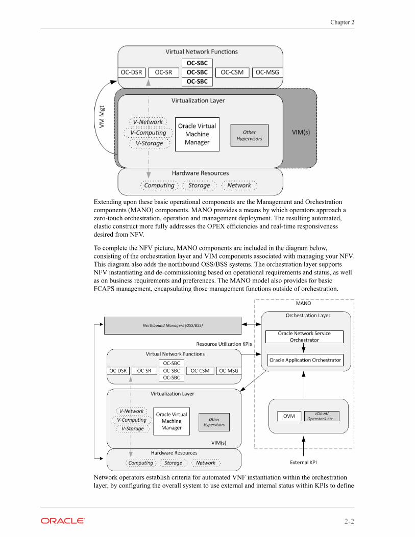
Extending upon these basic operational components are the Management and Orchestrationcomponents (MANO) components. MANO provides a means by which operators approach azero-touch orchestration, operation and management deployment. The resulting automated,elastic construct more fully addresses the OPEX efficiencies and real-time responsivenessdesired from NFV.
To complete the NFV picture, MANO components are included in the diagram below,consisting of the orchestration layer and VIM components associated with managing your NFV.This diagram also adds the northbound OSS/BSS systems. The orchestration layer supportsNFV instantiating and de-commissioning based on operational requirements and status, as wellas on business requirements and preferences. The MANO model also provides for basicFCAPS management, encapsulating those management functions outside of orchestration.
Network operators establish criteria for automated VNF instantiation within the orchestrationlayer, by configuring the overall system to use external and internal status within KPIs to define
Chapter 2
2-2

the triggers for changes to VNF resources. VNFs themselves provide critical status informationthat, when combined with organizational policy and other status triggers, the MANO uses toadjust network resources to network requirements in real time.
Oracle's NFV solution harnesses the extensive assets from its portfolio to deliver a vision of anetwork orchestration being driven by a business orchestration, which in turn delivers businessvalue to the customer. This vision builds on the investment that Oracle Communications hasmade in the BSS/OSS domain to deliver a BSS/OSS that is orchestrated along businessprocesses. The Oracle Communication Network Service Orchestrator provides the join of thetwo worlds by bridging the chiasm between Network Orchestration and Business Orchestration.
Oracle's NFV solution builds on the investment Oracle has made in the network domain to havean extensive portfolio of Network Functions as well as network orchestration.
Chapter 2
2-3
3Introduction to Platform Preparation andSoftware Deployment
This section introduces the deployment of Oracle Communications software onto the platformssupported by this version of the Oracle Communications Session Border Controller. ifapplicable, refer to Hardware Installation documentation for rack and stack procedures. Thisdocumentation explains platform preparation, power-on and software deployment to the pointwhere the user is ready to perform service configuration.
Platform support by Oracle Communications session delivery software extends to genericplatforms. As such, preparation of these platforms requires that the user perform tasksindependent of their session delivery product. Although the user needs to use platformdocumentation for this platform-specific information, Oracle distributes this documentation toprovide the user with:
• Settings required by the session delivery software.
• Guidance to procedures that apply to session delivery software.
Virtual MachinesVirtual Machines (VMs) supported by Oracle Communications Session Delivery softwarevaries across software version. Find specific version support within the context of yourversion's documentation.
Operation over VMs is roughly equivalent to deployment over COTS/Server hardware.Platform preparation, however, differs greatly. In addition, platform preparation differs greatlybetween VM platforms.
Preparation procedures that apply to all VM platforms include the following steps:
1. Make the VM template available to the VM manager.
2. Configure the VM manager to apply the template correctly for Oracle CommunicationsSession Delivery software.
3. Power-on the VM. If the deployment is using a VM template, the system uses that templateto automatically install onto the virtual drive, after which the server reboots. Deploymentsusing raw images do not perform an installation process.
VM deployment requires extensive knowledge about the specific platform that is notdocumented herein. The intent of this documentation is to provide information that helps theuser navigate the deployment and perform tasks that are specifically related to OracleCommunications Session Delivery software.
3-1
4Virtual Machine Platforms
Oracle distributes virtual machine templates, each containing a virtual disk image and defaultconfiguration for the supported profile of each VM platform. VM platform support isdependent on your Oracle product version.
This section addresses requirements associated with running applicable software as virtualmachines. It also provides basic instructions on loading and starting machine templates.
VM distributors maintain extensive documentation sites. You must use those vendors'documentation for full explanations and instructions on VM deployment and operation.
Create and Deploy on Oracle VM ManagerThis section provides detail on deploying Oracle Communications Session Delivery products inan Oracle Virtual Machine environment and assumes Oracle VM Manager 3.4.2. The sectionalso assumes the user understands deployment in these environments and that the majority ofdeployment tasks, from hardware installation and startup to VM resource and managementsetup, is complete.
For information on Oracle OVM, including server and manager documentation, refer to thefollowing links. The bottom link opens the page specifically to Oracle OVM version 3.4.2.
http://www.oracle.com/technetwork/documentation/vm-096300.htmlhttp://docs.oracle.com/cd/E64076_01/
Once hardware, VM resources and VM management are in place, the user prepares the VMmanagement environment. High level steps include:
• Discover Oracle VM Servers
• Discover Storage (File Server or SAN)
• Create a Virtual Machine Network
• Create a Server Pool
• Create a Storage Repository
Note:
The following procedure describes a typical deployment. The system may displaydifferent screens, depending on the deployment.
Oracle Communications Session Delivery product-specific setup steps include the following.
• Add Resources to Storage Repository
– Import an assembly
– Import a virtual machine template (from the assembly)
4-1
• Create a virtual machine from a template
• Configure processing resources
• Assign Networks
• Specify Boot Order
• Connect to the console
• Start your virtual machine
Use the Oracle VM Manager to deploy your VMs. Browsing the manager displays themanagement application, with tabs across the top for VM Manager configuration and display,and two panes providing access to controls and components for specific VM management.
Follow the steps below to deploy your VM(s):
1. From the Oracle VM Manager application Home page, navigate to the Repositories tab.
2. Click the Virtual Appliances folder on the left pane, then click the download icon fromthe center pane.
Oracle VM Manager displays the Import Virtual Appliance dialog.
3. Type the URL, either the HTTP or the FTP server, of your .ova appliance into the VirtualAppliance download location text box.
4. Check the Create VM checkbox.
5. Select the server pool to which your new machine belongs from the Server Pooldropdown.
6. Click OK.
Oracle VM manager creates your Virtual Machine.
7. Select VM Files folder on the left pane and verify the file is present.
8. Select the Servers and VMs tab and select the server pool.
9. Click on the Perspective drop down menu and select Virtual Machines.
10. Right click on the Virtual Machine and select Edit.
11. Edit your VM to configure the desired CPU, memory and core resources. Consider thefollowing settings:
• Operating System - Oracle Linux 7
• Domain Type - XEN HVM PV Drivers
• Memory - Set according to your deployment (defaults to 8G)
• Processors - Set according to your deployment (defaults to 4)
12. Open the Networks tab to manage your networks using the Network drop-down selectionbox. OVM does not display MAC addresses until the user applies the configuration.
The SBC enumerates and binds network interfaces in the order presented by the hypervisorto the virtual machine. If it presents 3 or less interfaces, the bind order is wancom0, s0p0,s1p0. If it presents more than 3 interfaces, the bind order is:
a. wancom0
b. wancom1
c. wancom2
d. spare
Chapter 4Create and Deploy on Oracle VM Manager
4-2
e. s0p0
f. s1p0
g. s0p1
h. s1p1
If your hypervisor randomly allocates addresses for network interfaces, the interface orderat the hypervisor does not necessarily match that at the SBC. You can use the interface-mapping show command to determine the MAC address to interface order, and ifnecessary, adjust it using the interface-mapping swap command.
13. If you want to increase the default disk size, click the Disks tab and the pencil icon to set alarger disk size.
Do not decrease disk size.
14. Click the Boot Order tab and ensure that Disk is the first (or only) option in the boot orderlist.
15. Click OK.
The system applies your settings to your VM.
16. Click the Console icon from the menu bar.
Oracle VM Manager displays a terminal screen with the serial CLI operational.
17. Highlight the target and click the Start button.
Oracle VM Manager starts your VM, displaying the startup sequence and, ultimately,providing ACLI access in the console.
Create and Deploy on KVMFor complete KVM documentation, refer to http://www.linux-kvm.org/page/Documents.
1. Install the Virtualization Host group and virt-install.
# yum groupinstall "Virtualization Host"# yum install virt-install
2. Extract the image.
# tar xvf nnSCZ739.64-img-vm_kvm.tarnnSCZ739.64-img-vm_kvm.ovfnnSCZ739.64-img-vm_kvm.qcow2legal.txt
3. Use virt-manager to create the management and media network interfaces.
• Create a virtual bridged network for management interfaces.
• Create virtual networks for media interfaces.
4. Provision a new virtual machine.
# virt-install \ --name SBC739 \ --description "nnSCZ739 KVM" \ --os-type=Linux \ --os-variant=rhel7 \ --ram=8192 \ --vcpus=4 \ --disk path=/opt/nnSCZ739.64-img-
Chapter 4Create and Deploy on KVM
4-3
vm_kvm.qcow2,bus=virtio,size=10,format=qcow2 \ --network bridge=br-Mgmt \ --network bridge=br-Mgmt \ --network bridge=br-Mgmt \ --network bridge=br-Mgmt \ --network network=media1 \ --network network=media2 \ --import \ --cpu host
Note:
Use interface-mapping to pin the four br-Mgmt network interfaces to wancom0,wancom1, wancom2, and spare.
--name
Identify a unique name for the virtual machine on this hypervisor.
--description
Describe this virtual machine.
--os-type
Specify the operating system type.
--os-variant
Optimize the configuration for a specific operating system.
--ram
Allocate a specific amount of RAM to this virtual machine.
--vcpus
Allocate a specific number of virtual CPUs to this virtual machine.
--disk
Specify the path to the disk image.
--network
Connect the virtual machine to a host network.
--import
Skip the operating system installation process and build a guest around the disk imagespecified with --disk.
--cpu
Configure the CPU model and CPU features exposed to the virtual machine.
See man virt-install for more information.
Note:
The --cpuset and --numatune options may be used to establish CPU affinity andsocket pinning.
Chapter 4Create and Deploy on KVM
4-4
Create and Deploy on VMware®This section provides detail on deploying Oracle Communications Session Delivery productsover the ESXI hypervisor and assumes VMware 6. The section also assumes the userunderstands deployment in these environments and that the majority of deployment tasks, fromhardware installation and startup to VM resource and management setup, is complete.
For information on VMware 6, which is also supported, refer to the following link.
https://www.vmware.com/support/pubs/vsphere-esxi-vcenter-server-6-pubs.html
Before You Begin:
• Confirm that the VMware version 6 Hypervisor is installed on an appropriate networkserver.
• Confirm that the server has 40GB of space for this installation.
Note:
The following procedure describes a typical deployment. The system may displaydifferent screens, depending on the deployment.
Detail on Oracle Communications Session Delivery product-specific setup steps is shownbelow.
1. On the vSphere Client application Home page, go to File > Deploy OVF Template File.
2. On the Source screen, browse to the target .ova file, and click Next.
3. On the End User License Agreement screen, click Accept and click Next.
4. On the Name and Location screen, do the following and click Next.
• Name. Enter a name for the template.
• Inventory Location. Select the location where you want to deploy the template.
5. On the Host / Cluster screen, select the host or cluster where you want to run the deployedtemplate, and click Next.
6. If applicable to your deployment, select the resource, from the Resource Pool screen, inwhich you want to deploy this template, and click Next.
7. On the Storage screen, select the destination storage for the virtual machine files, and clickNext.
8. On the Disk Format screen, select Thick Provisioned Lazy Zeroed, and click Next.
9. On the Network Mapping screen, map the networks used in this template to networks inyour inventory, and click Next.
The SBC enumerates and binds network interfaces in the order presented by the hypervisorto the virtual machine. If 3 or less interfaces are presented, the bind order is wancom0,s0p0, s1p0. If more than 3 interfaces are presented, the bind order is:
a. wancom0
b. wancom1
Chapter 4Create and Deploy on VMware®
4-5
c. wancom2
d. spare
e. s0p0
f. s1p0
g. s0p1
h. s1p1
If your hypervisor randomly allocates addresses for network interfaces, the interface orderat the hypervisor does not necessarily match that at the SBC. You can use the interface-mapping show command to determine the MAC address to interface order, and ifnecessary, adjust it using the interface-mapping swap command.
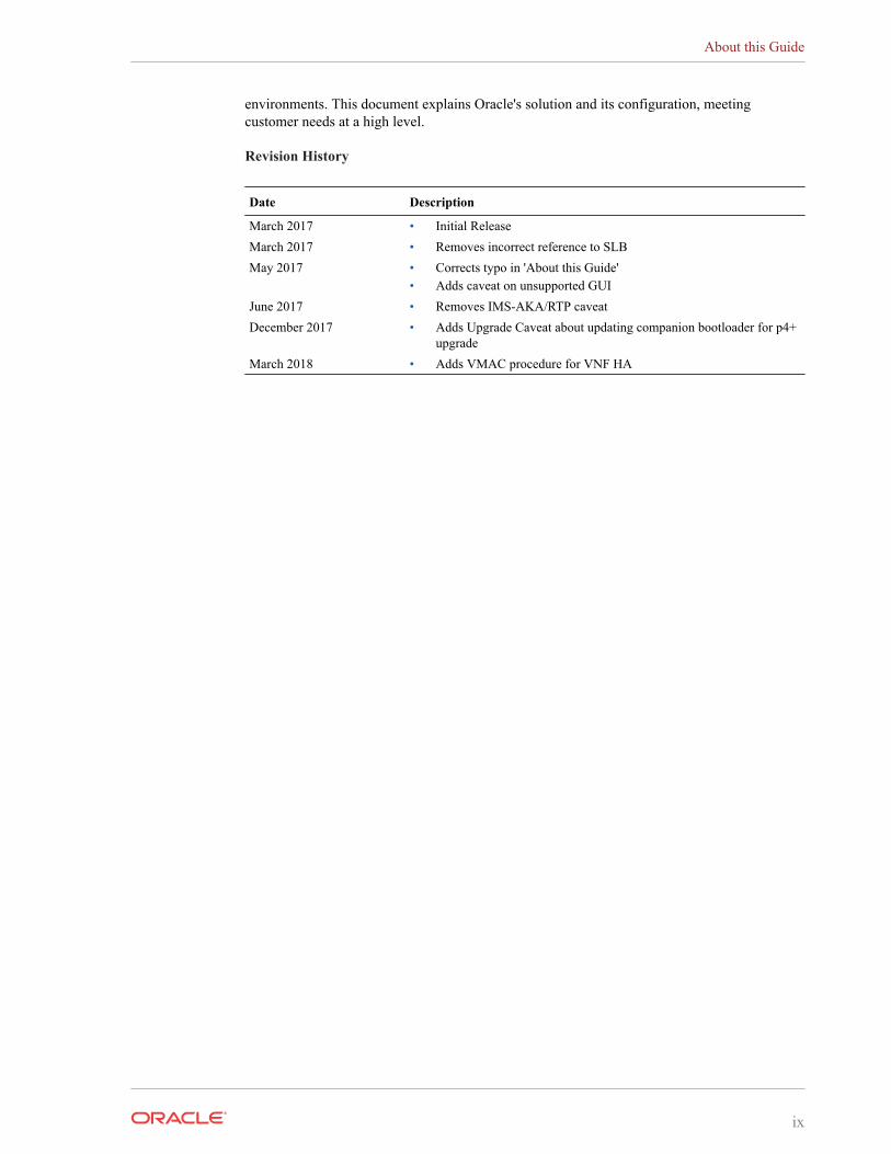
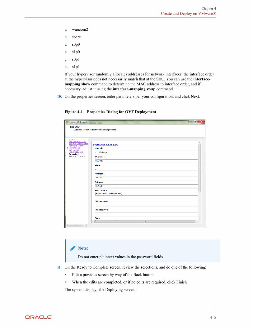
10. On the properties screen, enter parameters per your configuration, and click Next.
Figure 4-1 Properties Dialog for OVF Deployment
Note:
Do not enter plaintext values in the password fields.
11. On the Ready to Complete screen, review the selections, and do one of the following:
• Edit a previous screen by way of the Back button.
• When the edits are completed, or if no edits are required, click Finish
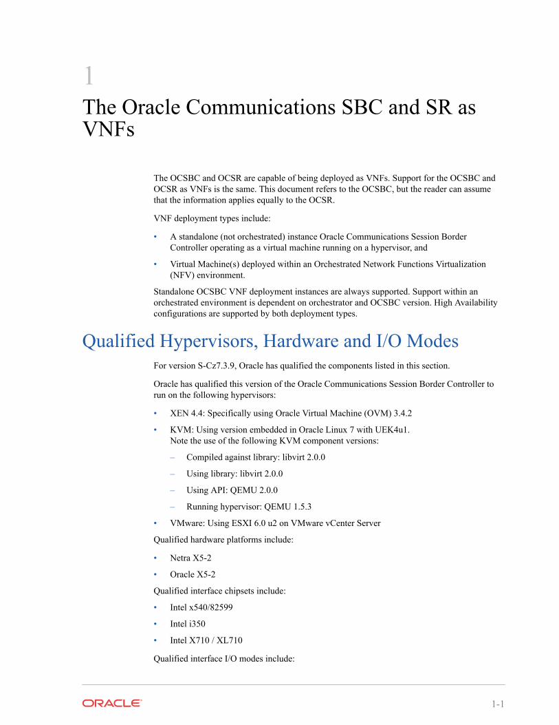
The system displays the Deploying screen.
Chapter 4Create and Deploy on VMware®
4-6
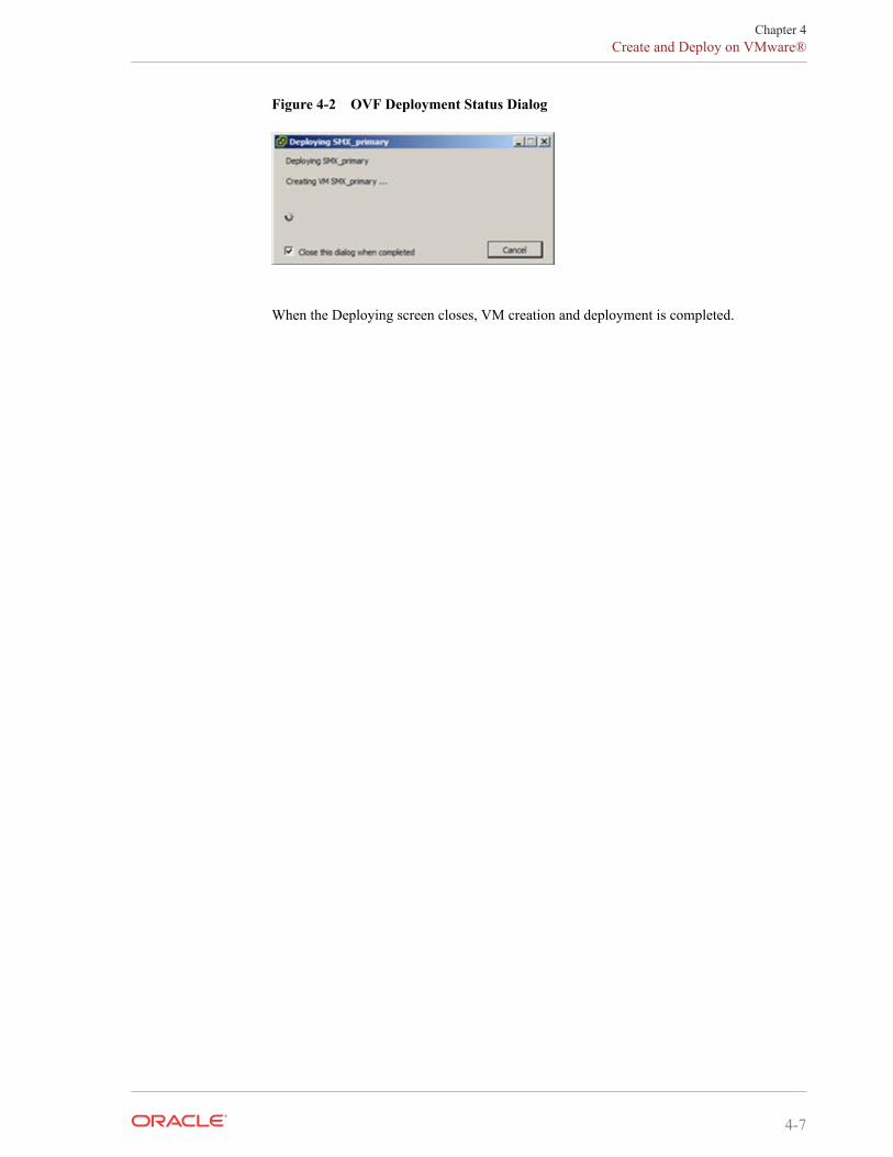
Figure 4-2 OVF Deployment Status Dialog
When the Deploying screen closes, VM creation and deployment is completed.
Chapter 4Create and Deploy on VMware®
4-7
5Configuring Your Device for NFV
Operating the Oracle Communications Session Border Controller as a VNF introducesconfiguration requirements that define resource utilization by the virtual machine. Theapplicable configuration elements allow the user to optimize resource utilization based on theapplication's needs and VM resource sharing.
Oracle Communications Session Border Controller configuration for VNF includes settings toaddress:
media-manager — Set media manager configuration elements to constrain bandwidthutilization, based on traffic type.
system-config > [core configuration parameters] — Set these parameters to specify CPUresources available to DoS, forwarding and transcoding processes.
Note:
Early versions of this software used the bootparameter named other, set toisolcpus=[value]. Remove this setting for this and all ensuing versions of OracleCommunications Session Border Controller software.
Media Manager ConfigurationThe Oracle Communications Session Border Controller provides the user with a means oftuning the media manager.
As the Oracle Communications Session Border Controller can classify traffic for use in DoSpolicing, bandwidth may be reserved for certain traffic types. Reserved bandwidth is expressedas a percentage of maximum available system bandwidth. The system's maximum bandwidth isdetermined by the hardware configuration and the number of available signaling cores. Themaximum system bandwidth is defined as the speed of ingress traffic sent to the host, measuredin packets per second (PPS). It is reported in the show platform limits command, referring tothe "Maximum Signaling rate".
The following configuration options are available in the media-manager-config. These optionsare used to configure reserved bandwidth for application signaling, and ARP, and untrustedtraffic.
• max-signaling-packets—Set the maximum overall bandwidth available for the host pathin packets per second, which includes signaling messages from trusted and untrustedsources. It also includes any Telnet and FTP traffic on media ports. The maximum valuefor each platform (shown below) is used as the default value for that platform. The validrange is:
– Minimum-71000
– Maximum-Depends on platform as shown below
* For COTs and VM platforms, the maximum is system dependent
5-1
• min-untrusted-signaling—The minimum percentage of maximum system bandwidthavailable for untrusted traffic. The rest of the bandwidth is available for trusted resources,but can also be used for untrusted sources per max-untrusted-signaling. Default: 30.Range: 1-100.
• max-untrusted-signaling—The percentage of the maximum signaling packets you wantto make available for messages coming from untrusted sources. This is a floatinghighwater mark and is only available when not in use by trusted sources. Default: 100.Range:1-100.
• tolerance-window—The size of the window, in seconds, used to measure host accesslimits for measuring the invalid message rate and maximum message rate for the realmconfiguration. Default: 30. Range: 0-4294967295.
• max-arp-rate—The maximum percentage or max-signaling-packets available for ARPtraffic. Default: 30. Range: 1-100.
The user can also set controls on untrusted traffic from either realm or static ACL configurationusing the untrusted-signal-threshold parameter.
Core ConfigurationThe user configures CPU core settings using system-config parameters. This configuration isbased on the specific needs of every individual implementation. These parameters allow theuser to set the number of cores they want to assign to forwarding, DoS, and transcodingfunctionality. The system determines which cores perform those functions, automaticallyassigning cores for optimal operation in each environment.
The user determines and manages their core configuration based on the services they need. Thesystem allocates cores to signaling upon installation. The user adds forwarding cores to matchtheir needs for handling media. The user also adds DoS and/or transcoding cores if they needthose functions in their deployment. The user must then reboot the system for coreconfiguration changes to take effect.
Note the following:
• By default, core 0 is always set to signaling.
• The system selects cores based on function; users do not assign cores.
• The system sets unassigned cores to signaling, with a maximum of 24.
When the user makes core assignments, the Oracle Communications Session Border Controllerprovides an error message if the system detects an issue. In addition, the system performs acheck when the user issues the verify-config command to ensure that the total number offorwarding, plus DOS, plus transcoding cores does not exceed the maximum number ofphysical cores. After the user saves and activates a configuration that includes a change to thecore configuration, the system displays a prompt to remind the user that a reboot is required forthe changes to take place.
The user can verify core configuration from the ACLI, using the show datapath-configcommand or after core configuration changes during the save and activation processes. Whenusing hyperthreading, which divides cores into a single physical (primary) and a single logical(secondary) core, this display may differ. Bear in mind that the Oracle Communications SessionBorder Controller binds functions to primary or secondary cores using its own criteria, withsecondary cores performing signaling functions only. Hypervisors that provide a view into thetype of core assigned to a function allow show datapath-config to display primary cores inupper-case letters and secondary cores in lower-case letters. Other hypervisors show all cores asphysical.
Chapter 5Core Configuration
5-2
The Oracle Communications Session Border Controller uses the following lettering (upper- andlower-case) in the ACLI to show core assignments:
• S - Signaling
• D - DoS
• F - Forwarding
• X - Transcoding
The system-config element includes the following parameters for core assignment:
• dos-cores— Sets the number of cores the system must allocate for DOS functionality. Amaximum of one core is allowed.
• forwarding-cores—Sets the number of cores the system must allocate for the forwardingengine. Valid values are from 1 to 128.
• transcoding-cores—Sets the number of cores the system must allocate for transcoding.Valid values are from 0 to 128, with a default of 0.
To change core assignments, access the system-config, as follows.
ORACLE# configure terminalORACLE(configure)# systemORACLE(system)# system-configORACLE(system-config)#
Change existing core assignment settings using the system-config parameters listed above. Forexample, to reserve a core for DoS processing:
ORACLE#(system-config) dos-cores 1
The Oracle Communications Session Border Controller VNF has no system-based maximumnumber of cores, other than the range of the system-config parameters.
Note:
Refer to the New in this Release section at the beginning of this Essentials Guide forany release-specific core configuration constraints.
The system checks CPU core resources before every boot, as configuration can affect resourcerequirements. Examples of such resource requirement variations include:
• There is at least 1 CPU assigned to signaling (by the system).
• If DoS is required, then there are at least 1 CPU assigned to forwarding and 1 to DoS.
• If DoS is not required, then there is at least 1 CPU assigned to forwarding.
The system performs resource utilization checks every time it boots for CPU, memory andhard-disk to avoid configuration/resource conflicts.
Core configuration is supported by HA. For HA systems, resource utilization on the backupmust be the same as the primary.
Chapter 5Core Configuration
5-3
Note:
The hypervisor always reports the datapath CPU usage fully utilized. This isolates aphysical CPU to this work load. However, this may cause the hypervisor to generate apersistent alarm indicating that the VM is using an excessive amount of CPU, possiblytriggering throttling. The user should configure their hypervisor monitoringappropriately, to avoid such throttling.
Virtual MAC Addresses for VNFsVirtual Network Functions (VNFs) rely on their hypervisor environment for MAC addressestablishment, advertisement and resolution. As such, you cannot derive these addresses usingthe same method as you do for Acme platforms. For VNFs, Oracle recommends establishingprivate MAC addressing for virtual MAC address configuration.
To support HA, you configure virtual Ethernet (MAC) address MAC addresses based on theBurned In Addresses (BIA) of the media interfaces. To determine what the virtual MACaddresses should be, you first identify a BIA and then calculate the virtual MACs based on that.
To define the virtual addresses you need to configure for each interface:
1. Identify the base MAC of eth0/wancom0 physical interface using the show interfacescommand. For example, in the following display, you can see the base MAC is00:50:56:C0:00:08:
eth(unit number 0):Flags: (0x78843) UP BROADCAST MULTICAST ARP RUNNING INET_UPType: ETHERNET_CSMACDinet: 111.22.0.123Broadcast address: 111.22.255.255Netmask 0xffff0000 Subnetmask 0xffff0000Ethernet address is 00:50:56:C0:00:08
2. Set the bottom nibble of the first byte to 2 to define the address as locally administered.
3. Set the top nibble of the first byte to 0 and increment it for each interface.
For example, using the base-MAC for eth0, 00:50:56:C0:00:08, you assign the virtualaddresses as follows:
• First media interface virtual MAC = 02:50:56:C0:00:08
• Second media interface virtual MAC = 12:50:56:C0:00:08
• Third media interface virtual MAC = 22:50:56:C0:00:08
• Forth media interface virtual MAC = 32:50:56:C0:00:08
System ShutdownUse the system's halt command to gracefully shutdown the VNF.
ACMEPACKET# halt
-------------------------------------------------------WARNING: you are about to halt this SD!-------------------------------------------------------
Chapter 5Virtual MAC Addresses for VNFs
5-4

Halt this SD [y/n]?:
See the ACLI Reference Guide for further information about this command.
Chapter 5System Shutdown
5-5
6Boot Management
Boot Management includes the tasks needed to ensure the system is operating according to theusers requirements as it starts up. Requirements met by properly managing system boot includedefining management access IP, specifying the load to boot and specifying a system name. Theuser may set this information manually or configure the operational environment to provide it.
Boot management consists of tasks working with the following:
• Boot Loaders—The user needs to perform file management tasks to ensure that thesoftware used to boot the system is compatible with the application system software itself.This typically includes verifying boot loader and application system software version forcompatibility and placing the correct boot loader software in the correct location.
• Boot Parameters—The user sets boot parameters to specify their requirements for boot,including defining management access IP, specifying the load to boot and specifying asystem name.
• Boot Flags—The user can, optionally, set special boot parameters called boot flags tofurther define how the system boots. The user may also set boot flags for diagnosticpurposes under the guidance of Oracle support personnel.
Boot ParametersBoot parameters specify the information that your device uses at boot time when it prepares torun applications.
This section explains how to view, edit, and implement device’s boot parameters, and bootflags. Boot parameters:
• Allow you to set the IP address for the management interface (wancom0).
• Allow you to set a system prompt. The target name parameter also specifies the title namedisplayed in your web browser and SNMP device name parameters.
• Specify the software image to boot and from where the system boots that image.
Boot flags are arguments to a specific boot parameter, and allow functional settings, such as theuse of DHCP for acquiring a management port address, as well as various diagnostic startupconfigurations.
Configuring boot parameters has repercussions on your system’s physical and networkinterface configurations. When you configure these interfaces, you can set values that mightoverride the boot parameters.
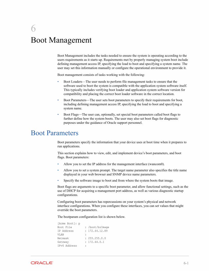
The bootparam configuration list is shown below.
[Acme Boot]: pBoot File : /boot/bzImageIP Address : 172.44.12.89VLAN :Netmask : 255.255.0.0Gateway : 172.44.0.1IPv6 Address :
6-1
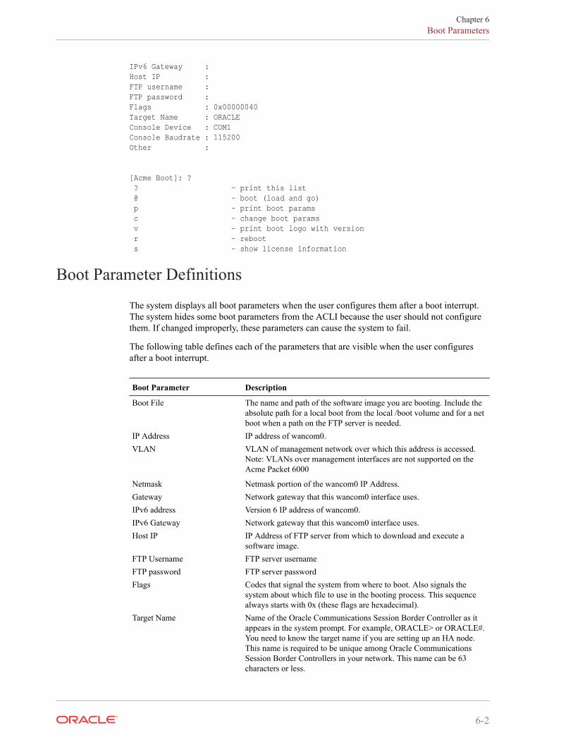
IPv6 Gateway : Host IP :FTP username :FTP password :Flags : 0x00000040Target Name : ORACLEConsole Device : COM1Console Baudrate : 115200Other :
[Acme Boot]: ? ? - print this list @ - boot (load and go) p - print boot params c - change boot params v - print boot logo with version r - reboot s - show license information
Boot Parameter Definitions
The system displays all boot parameters when the user configures them after a boot interrupt.The system hides some boot parameters from the ACLI because the user should not configurethem. If changed improperly, these parameters can cause the system to fail.
The following table defines each of the parameters that are visible when the user configuresafter a boot interrupt.
Boot Parameter Description
Boot File The name and path of the software image you are booting. Include theabsolute path for a local boot from the local /boot volume and for a netboot when a path on the FTP server is needed.
IP Address IP address of wancom0.VLAN VLAN of management network over which this address is accessed.
Note: VLANs over management interfaces are not supported on theAcme Packet 6000
Netmask Netmask portion of the wancom0 IP Address.Gateway Network gateway that this wancom0 interface uses.IPv6 address Version 6 IP address of wancom0.IPv6 Gateway Network gateway that this wancom0 interface uses.Host IP IP Address of FTP server from which to download and execute a
software image.FTP Username FTP server usernameFTP password FTP server passwordFlags Codes that signal the system from where to boot. Also signals the
system about which file to use in the booting process. This sequencealways starts with 0x (these flags are hexadecimal).
Target Name Name of the Oracle Communications Session Border Controller as itappears in the system prompt. For example, ORACLE> or ORACLE#.You need to know the target name if you are setting up an HA node.This name is required to be unique among Oracle CommunicationsSession Border Controllers in your network. This name can be 63characters or less.
Chapter 6Boot Parameters
6-2
Boot Parameter Description
Console Device Serial output device type, dependent on platform. COM1 applies tovirtual serial consoles, VGA to virtual video console. VGA is thedefault on VMware and KVM. COM1 is the default on OVM .
Console Baud Rate The speed in bits per second which the console port operates at. Itoperates at 115200 BPS, 8 data bits, no stop bit, parity NONE.
Other Allows miscellaneous and deployment-specific boot settings.
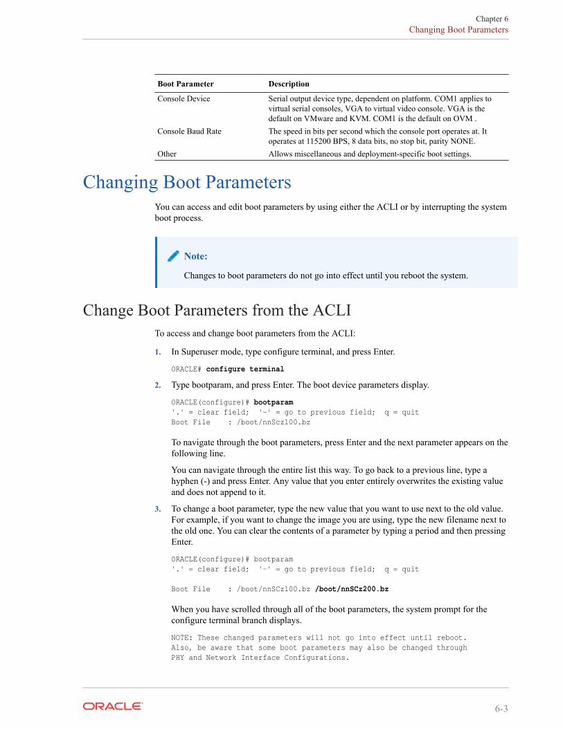
Changing Boot ParametersYou can access and edit boot parameters by using either the ACLI or by interrupting the systemboot process.
Note:
Changes to boot parameters do not go into effect until you reboot the system.
Change Boot Parameters from the ACLITo access and change boot parameters from the ACLI:
1. In Superuser mode, type configure terminal, and press Enter.
ORACLE# configure terminal
2. Type bootparam, and press Enter. The boot device parameters display.
ORACLE(configure)# bootparam'.' = clear field; '-' = go to previous field; q = quitBoot File : /boot/nnScz100.bz
To navigate through the boot parameters, press Enter and the next parameter appears on thefollowing line.
You can navigate through the entire list this way. To go back to a previous line, type ahyphen (-) and press Enter. Any value that you enter entirely overwrites the existing valueand does not append to it.
3. To change a boot parameter, type the new value that you want to use next to the old value.For example, if you want to change the image you are using, type the new filename next tothe old one. You can clear the contents of a parameter by typing a period and then pressingEnter.
ORACLE(configure)# bootparam'.' = clear field; '-' = go to previous field; q = quit
Boot File : /boot/nnSCz100.bz /boot/nnSCz200.bz
When you have scrolled through all of the boot parameters, the system prompt for theconfigure terminal branch displays.
NOTE: These changed parameters will not go into effect until reboot.Also, be aware that some boot parameters may also be changed throughPHY and Network Interface Configurations.
Chapter 6Changing Boot Parameters
6-3
ORACLE(configure)#
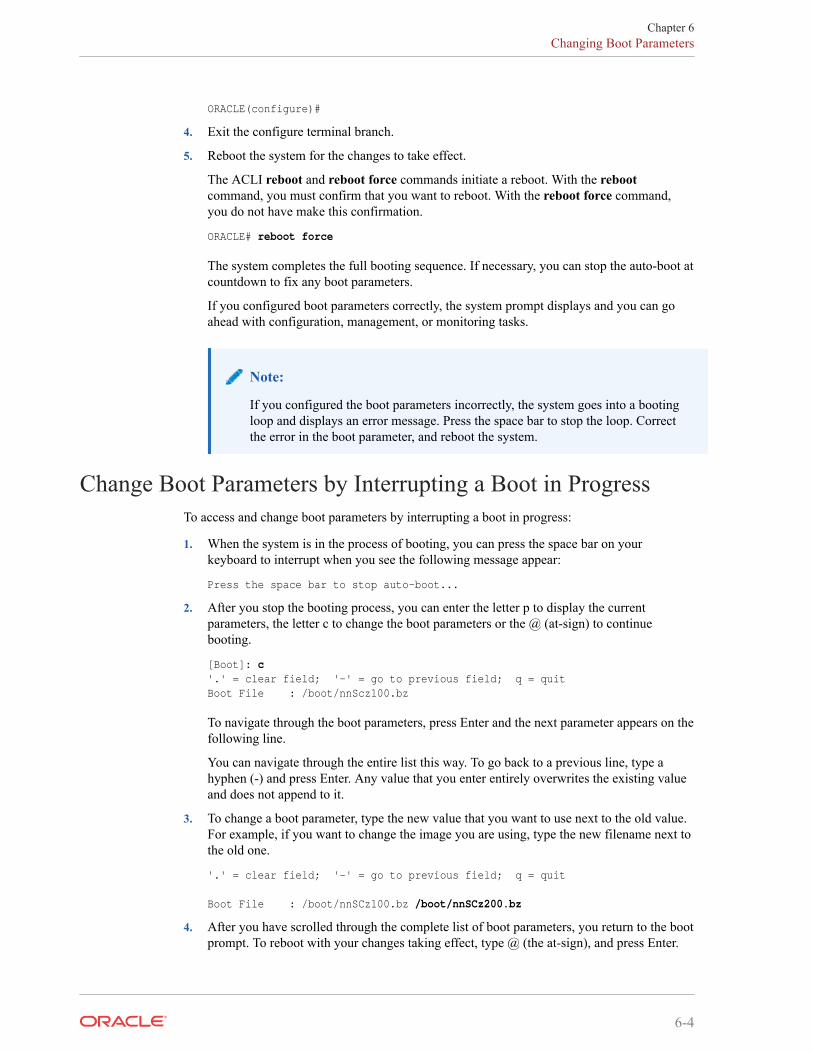
4. Exit the configure terminal branch.
5. Reboot the system for the changes to take effect.
The ACLI reboot and reboot force commands initiate a reboot. With the rebootcommand, you must confirm that you want to reboot. With the reboot force command,you do not have make this confirmation.
ORACLE# reboot force
The system completes the full booting sequence. If necessary, you can stop the auto-boot atcountdown to fix any boot parameters.
If you configured boot parameters correctly, the system prompt displays and you can goahead with configuration, management, or monitoring tasks.
Note:
If you configured the boot parameters incorrectly, the system goes into a bootingloop and displays an error message. Press the space bar to stop the loop. Correctthe error in the boot parameter, and reboot the system.
Change Boot Parameters by Interrupting a Boot in ProgressTo access and change boot parameters by interrupting a boot in progress:
1. When the system is in the process of booting, you can press the space bar on yourkeyboard to interrupt when you see the following message appear:
Press the space bar to stop auto-boot...
2. After you stop the booting process, you can enter the letter p to display the currentparameters, the letter c to change the boot parameters or the @ (at-sign) to continuebooting.
[Boot]: c'.' = clear field; '-' = go to previous field; q = quitBoot File : /boot/nnScz100.bz
To navigate through the boot parameters, press Enter and the next parameter appears on thefollowing line.
You can navigate through the entire list this way. To go back to a previous line, type ahyphen (-) and press Enter. Any value that you enter entirely overwrites the existing valueand does not append to it.
3. To change a boot parameter, type the new value that you want to use next to the old value.For example, if you want to change the image you are using, type the new filename next tothe old one.
'.' = clear field; '-' = go to previous field; q = quit
Boot File : /boot/nnSCz100.bz /boot/nnSCz200.bz
4. After you have scrolled through the complete list of boot parameters, you return to the bootprompt. To reboot with your changes taking effect, type @ (the at-sign), and press Enter.
Chapter 6Changing Boot Parameters
6-4
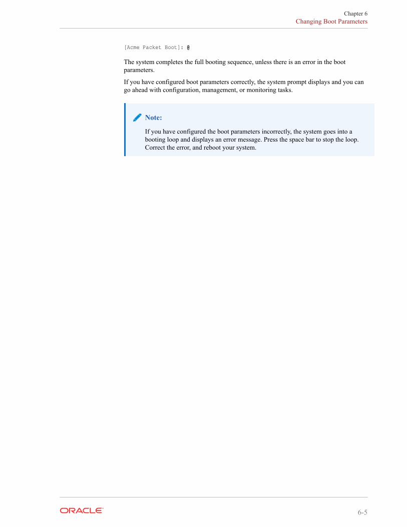
[Acme Packet Boot]: @
The system completes the full booting sequence, unless there is an error in the bootparameters.
If you have configured boot parameters correctly, the system prompt displays and you cango ahead with configuration, management, or monitoring tasks.
Note:
If you have configured the boot parameters incorrectly, the system goes into abooting loop and displays an error message. Press the space bar to stop the loop.Correct the error, and reboot your system.
Chapter 6Changing Boot Parameters
6-5
7Formatting Disks for VM Deployments
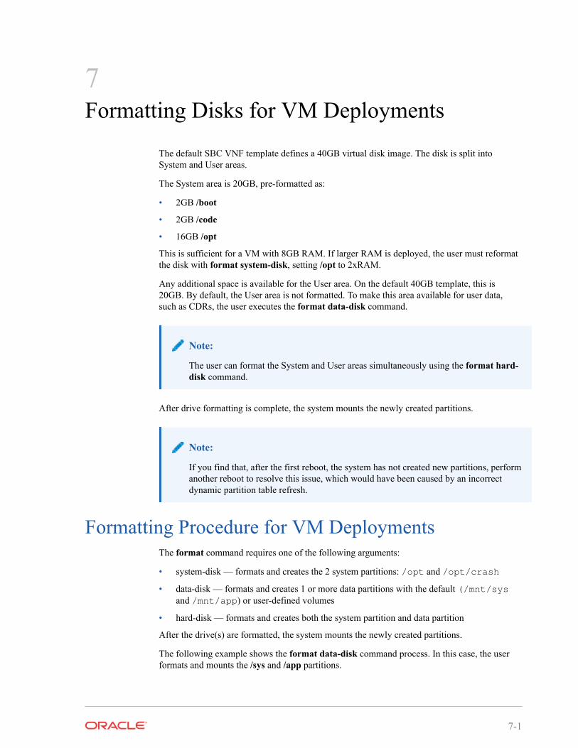
The default SBC VNF template defines a 40GB virtual disk image. The disk is split intoSystem and User areas.
The System area is 20GB, pre-formatted as:
• 2GB /boot
• 2GB /code
• 16GB /opt
This is sufficient for a VM with 8GB RAM. If larger RAM is deployed, the user must reformatthe disk with format system-disk, setting /opt to 2xRAM.
Any additional space is available for the User area. On the default 40GB template, this is20GB. By default, the User area is not formatted. To make this area available for user data,such as CDRs, the user executes the format data-disk command.
Note:
The user can format the System and User areas simultaneously using the format hard-disk command.
After drive formatting is complete, the system mounts the newly created partitions.
Note:
If you find that, after the first reboot, the system has not created new partitions, performanother reboot to resolve this issue, which would have been caused by an incorrectdynamic partition table refresh.
Formatting Procedure for VM DeploymentsThe format command requires one of the following arguments:
• system-disk — formats and creates the 2 system partitions: /opt and /opt/crash
• data-disk — formats and creates 1 or more data partitions with the default (/mnt/sysand /mnt/app) or user-defined volumes
• hard-disk — formats and creates both the system partition and data partition
After the drive(s) are formatted, the system mounts the newly created partitions.
The following example shows the format data-disk command process. In this case, the userformats and mounts the /sys and /app partitions.
7-1
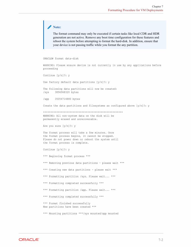
Note:
The format command may only be executed if certain tasks like local CDR and HDRgeneration are not active. Remove any boot time configuration for these features andreboot the system before attempting to format the hard-disk. In addition, ensure thatyour device is not passing traffic while you format the any partition.
ORACLE# format data-disk
WARNING: Please ensure device is not currently in use by any applications before proceeding
Continue [y/n]?: y
Use factory default data partitions [y/n]?: y
The following data partitions will now be created:/sys 3894968320 bytes /app 35054714880 bytes
Create the data partitions and filesystems as configured above [y/n]?: y
******************************************************WARNING: All non-system data on the disk will bepermanently erased and unrecoverable.
Are you sure [y/n]?: y
The format process will take a few minutes. Oncethe format process begins, it cannot be stopped.Please do not power down or reboot the system untilthe format process is complete.
Continue [y/n]?: y
*** Beginning format process ***
*** Removing previous data partitions - please wait ***
*** Creating new data partitions - please wait ***
*** Formatting partition /sys. Please wait... ***
*** Formatting completed successfully ***
*** Formatting partition /app. Please wait... ***
*** Formatting completed successfully ***
*** Format finished successfullyNew partitions have been created ***
*** Mounting partitions ***/sys mounted/app mounted
Chapter 7Formatting Procedure for VM Deployments
7-2
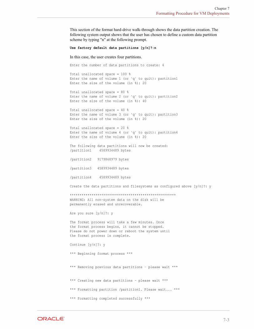
This section of the format hard-drive walk-through shows the data partition creation. Thefollowing system output shows that the user has chosen to define a custom data partitionscheme by typing "n" at the following prompt.
Use factory default data partitions [y/n]?:n
In this case, the user creates four partitions.
Enter the number of data partitions to create: 4
Total unallocated space = 100 %Enter the name of volume 1 (or 'q' to quit): partition1Enter the size of the volume (in %): 20
Total unallocated space = 80 %Enter the name of volume 2 (or 'q' to quit): partition2Enter the size of the volume (in %): 40
Total unallocated space = 40 %Enter the name of volume 3 (or 'q' to quit): partition3Enter the size of the volume (in %): 20
Total unallocated space = 20 %Enter the name of volume 4 (or 'q' to quit): partition4Enter the size of the volume (in %): 20
The following data partitions will now be created:/partition1 4589934489 bytes
/partition2 9179868979 bytes
/partition3 4589934489 bytes
/partition4 4589934489 bytes
Create the data partitions and filesystems as configured above [y/n]?: y
******************************************************WARNING: All non-system data on the disk will bepermanently erased and unrecoverable.
Are you sure [y/n]?: y
The format process will take a few minutes. Oncethe format process begins, it cannot be stopped.Please do not power down or reboot the system untilthe format process is complete.
Continue [y/n]?: y
*** Beginning format process ***
*** Removing previous data partitions - please wait ***
*** Creating new data partitions - please wait ***
*** Formatting partition /partition1. Please wait... ***
*** Formatting completed successfully ***
Chapter 7Formatting Procedure for VM Deployments
7-3
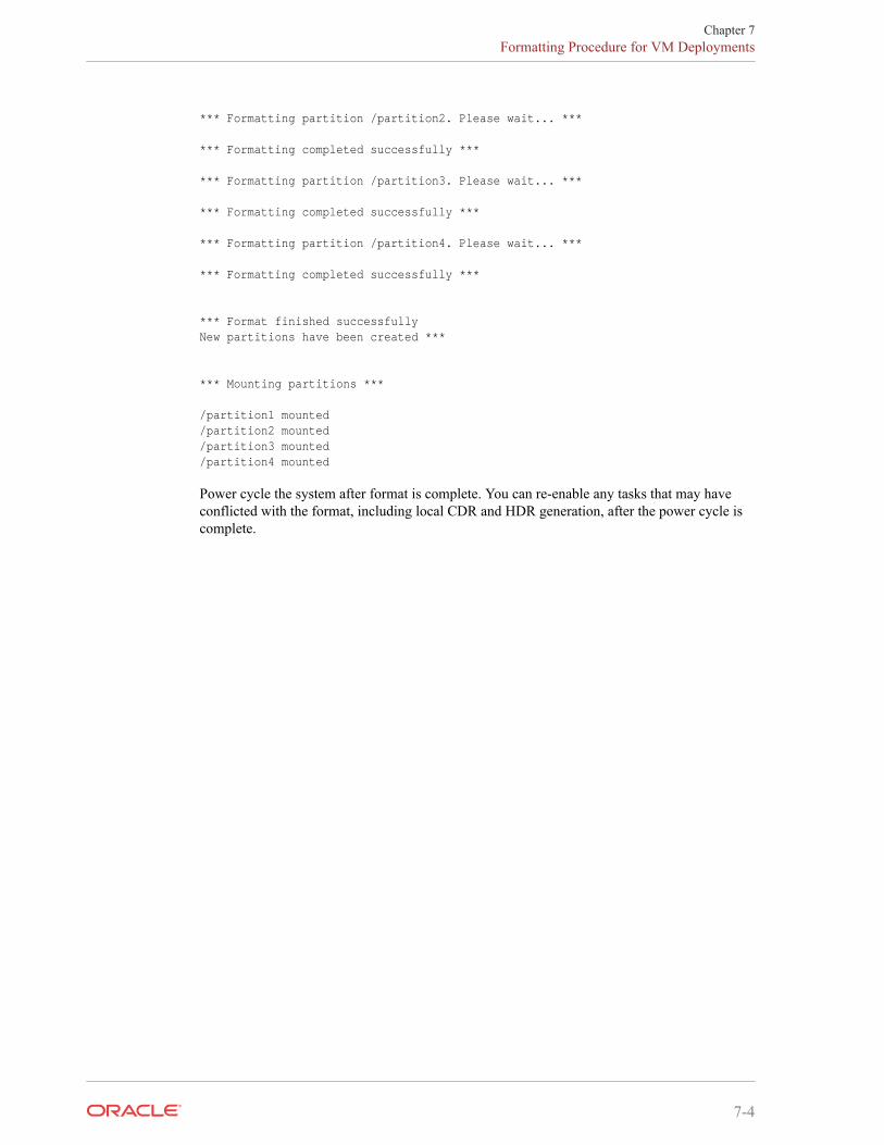
*** Formatting partition /partition2. Please wait... ***
*** Formatting completed successfully ***
*** Formatting partition /partition3. Please wait... ***
*** Formatting completed successfully ***
*** Formatting partition /partition4. Please wait... ***
*** Formatting completed successfully ***
*** Format finished successfullyNew partitions have been created ***
*** Mounting partitions ***
/partition1 mounted/partition2 mounted/partition3 mounted/partition4 mounted
Power cycle the system after format is complete. You can re-enable any tasks that may haveconflicted with the format, including local CDR and HDR generation, after the power cycle iscomplete.
Chapter 7Formatting Procedure for VM Deployments
7-4
8VM Interfaces
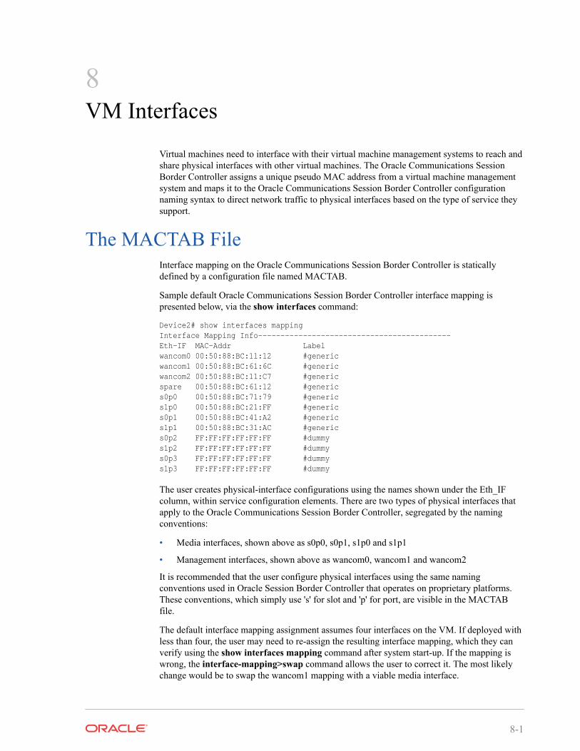
Virtual machines need to interface with their virtual machine management systems to reach andshare physical interfaces with other virtual machines. The Oracle Communications SessionBorder Controller assigns a unique pseudo MAC address from a virtual machine managementsystem and maps it to the Oracle Communications Session Border Controller configurationnaming syntax to direct network traffic to physical interfaces based on the type of service theysupport.
The MACTAB FileInterface mapping on the Oracle Communications Session Border Controller is staticallydefined by a configuration file named MACTAB.
Sample default Oracle Communications Session Border Controller interface mapping ispresented below, via the show interfaces command:
Device2# show interfaces mappingInterface Mapping Info-------------------------------------------Eth-IF MAC-Addr Labelwancom0 00:50:88:BC:11:12 #genericwancom1 00:50:88:BC:61:6C #genericwancom2 00:50:88:BC:11:C7 #genericspare 00:50:88:BC:61:12 #generics0p0 00:50:88:BC:71:79 #generics1p0 00:50:88:BC:21:FF #generics0p1 00:50:88:BC:41:A2 #generics1p1 00:50:88:BC:31:AC #generics0p2 FF:FF:FF:FF:FF:FF #dummys1p2 FF:FF:FF:FF:FF:FF #dummys0p3 FF:FF:FF:FF:FF:FF #dummys1p3 FF:FF:FF:FF:FF:FF #dummy
The user creates physical-interface configurations using the names shown under the Eth_IFcolumn, within service configuration elements. There are two types of physical interfaces thatapply to the Oracle Communications Session Border Controller, segregated by the namingconventions:
• Media interfaces, shown above as s0p0, s0p1, s1p0 and s1p1
• Management interfaces, shown above as wancom0, wancom1 and wancom2
It is recommended that the user configure physical interfaces using the same namingconventions used in Oracle Session Border Controller that operates on proprietary platforms.These conventions, which simply use 's' for slot and 'p' for port, are visible in the MACTABfile.
The default interface mapping assignment assumes four interfaces on the VM. If deployed withless than four, the user may need to re-assign the resulting interface mapping, which they canverify using the show interfaces mapping command after system start-up. If the mapping iswrong, the interface-mapping>swap command allows the user to correct it. The most likelychange would be to swap the wancom1 mapping with a viable media interface.
8-1
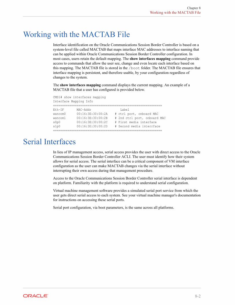
Working with the MACTAB FileInterface identification on the Oracle Communications Session Border Controller is based on asystem-level file called MACTAB that maps interface MAC addresses to interface naming thatcan be applied within Oracle Communications Session Border Controller configuration. Inmost cases, users retain the default mapping. The show interfaces mapping command provideaccess to commands that allow the user see, change and even locate each interface based onthis mapping. The MACTAB file is stored in the /boot folder. The MACTAB file ensures thatinterface mapping is persistent, and therefore usable, by your configuration regardless ofchanges to the system.
The show interfaces mapping command displays the current mapping. An example of aMACTAB file that a user has configured is provided below.
CMS1# show interfaces mappingInterface Mapping Info============================================================Eth-IF MAC-Addr Labelwancom0 00:16:3E:30:00:2A # ctrl port, onboard MACwancom1 00:16:3E:30:00:2B # 2nd ctrl port, onboard MACs0p0 00:16:3E:30:00:2C # First media interfaces1p0 00:16:3E:30:00:2D # Second media interrface============================================================
Serial InterfacesIn lieu of IP management access, serial access provides the user with direct access to the OracleCommunications Session Border Controller ACLI. The user must identify how their systemallows for serial access. The serial interface can be a critical component of VM interfaceconfiguration as the user can make MACTAB changes via the serial interface withoutinterrupting their own access during that management procedure.
Access to the Oracle Communications Session Border Controller serial interface is dependenton platform. Familiarity with the platform is required to understand serial configuration.
Virtual machine management software provides a simulated serial port service from which theuser gets direct serial access to each system. See your virtual machine manager's documentationfor instructions on accessing these serial ports.
Serial port configuration, via boot parameters, is the same across all platforms.
Chapter 8Working with the MACTAB File
8-2
9References and Debugging
Packet Trace Over Systems using DPDKThe Oracle Communications Session Border Controller's packet trace tool provides the userwith the ability to capture traffic from the Oracle Communications Session Border Controlleritself. The packet capture command is documented elsewhere, but the syntax and operation forsystems using DPDK is not the same.
There are two capture modes across the product line, one that saves traffic locally and one thatmirrors traffic to a user-specified target. Software only deployments, including S-CZ7.3.9,support local capture only.
The user invokes the tool from the ACLI, manually specifying:
• How to capture (local only for S-CZ7.3.9)
• What to capture
• Capture start and stop
Local capture supports PCAP filters to specify the signaling traffic you want to capture. Thedefault packet trace filter uses the specified interface to capture both ingress and egress traffic.The user can then use the packet-trace command's syntax to filter based on target IP ad well aslocal and remote port. To further specify captured traffic, the user can also append thecommand with a PCAP filter enclosed in quotes. PCAP filter syntax is widely published.
The user can run only a single capture on a given interface. However, the user can run multiplecaptures simultaneously, as long as they are on separate interfaces.
Local packet capture is dependent on access control configuration, not capturing any deniedtraffic.
Note:
Do not run packet-trace simultaneously with other Oracle Communications SessionBorder Controller replication features, such as LI, SRS, SIP Monitoring and Trace, andCall Recording. These features may interfere with each other, corrupting each's results.
Packet Trace Local enables the Oracle Communications Session Border Controller to capturetraffic between two endpoints, or between itself and a specific endpoint. To accomplish this, theOracle Communications Session Border Controller replicates the packets sent and received andsaves them to disk in .PCAP format.
By default, the system saves the .PCAP file in /opt/traces, naming it with the applicableinterface name as well as the date and time of the capture. Alternatively, the user can specifyfile name using the system supports the PCAP filter flags -w.
The system rotates the PCAPs created in this directory by size. The last 25 files are kept andare rotated when they reach 100 MB. If there are capture files in the /opt/traces directory when
9-1
this command is run, the system prompts the user to remove them before running new captures.If preferred, the user can decline this file deletion.
Starting a Local Packet Trace on Systems Running DPDKYou use the start a packet trace by entering the appropriate ACLI command with these pieces ofinformation:
• Network interface (name:subport ID combination)
• (Optional) IP address to be traced; if you do not enter local and/or remote ports when youstart the trace, the Oracle Communications Session Border Controller traces all opensockets.
• (Optional) Local UDP/TCP port on which the Oracle Communications Session BorderController sends and receives traffic to be traced.
• (Optional) Remote UDP/TCP port to which the Oracle Communications Session BorderController sends traffic, and from which it receives traffic to be traced; you cannot enterthe remote port without specifying a local port.
• (Optional) Enter a tcpdump command line within quotes.
Note that the system supports local packet trace on all platforms. To start a packet trace withlocal and remote ports specified:
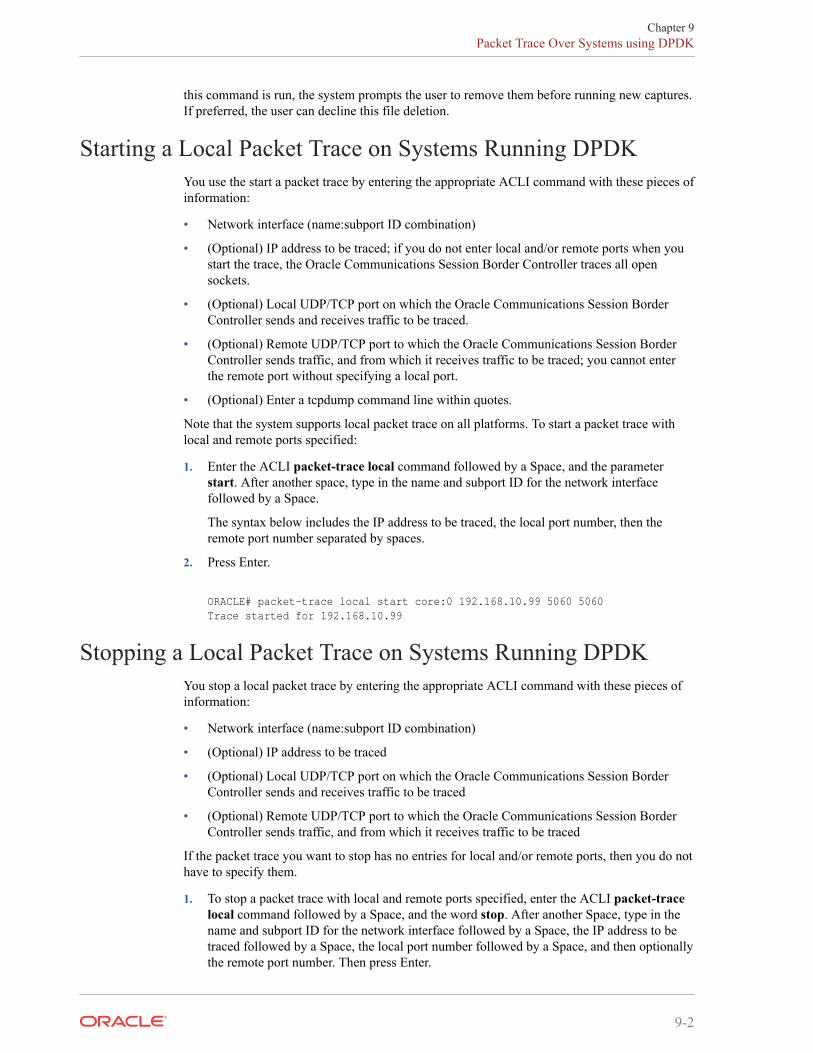
1. Enter the ACLI packet-trace local command followed by a Space, and the parameterstart. After another space, type in the name and subport ID for the network interfacefollowed by a Space.
The syntax below includes the IP address to be traced, the local port number, then theremote port number separated by spaces.
2. Press Enter.
ORACLE# packet-trace local start core:0 192.168.10.99 5060 5060Trace started for 192.168.10.99
Stopping a Local Packet Trace on Systems Running DPDKYou stop a local packet trace by entering the appropriate ACLI command with these pieces ofinformation:
• Network interface (name:subport ID combination)
• (Optional) IP address to be traced
• (Optional) Local UDP/TCP port on which the Oracle Communications Session BorderController sends and receives traffic to be traced
• (Optional) Remote UDP/TCP port to which the Oracle Communications Session BorderController sends traffic, and from which it receives traffic to be traced
If the packet trace you want to stop has no entries for local and/or remote ports, then you do nothave to specify them.
1. To stop a packet trace with local and remote ports specified, enter the ACLI packet-tracelocal command followed by a Space, and the word stop. After another Space, type in thename and subport ID for the network interface followed by a Space, the IP address to betraced followed by a Space, the local port number followed by a Space, and then optionallythe remote port number. Then press Enter.
Chapter 9Packet Trace Over Systems using DPDK
9-2
ORACLE# packet-trace local stop core:0 192.168.10.99 5060 5060
2. To stop all packet traces on the Oracle Communications Session Border Controller, enterthe ACLI packet-trace local command followed by a Space, and the word stop. Afteranother Space, type the word all and press Enter.
ORACLE# packet-trace local stop all
SNMP MIBs and TrapsThe following MIBs and traps are supported for the Oracle Communications Session BorderController. Please consult the Oracle Communications Session Border Controller MIBReference Guide for more SNMP information.
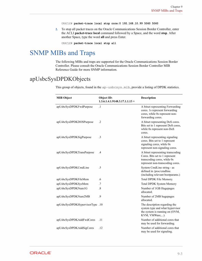
apUsbcSysDPDKObjectsThis group of objects, found in the ap-usbcsys.mib, provide a listing of DPDK statistics.
MIB Object Object ID:1.3.6.1.4.1.9148.3.17.1.1.13 +
Description
apUsbcSysDPDKFwdPurpose .1 A bitset representing Forwardingcores. 1s represent forwardingcores, while 0s represent non-forwarding cores.
apUsbcSysDPDKDOSPurpose .2 A bitset representing DoS cores.Bits set to 1 represent DoS cores,while 0s represent non-DoScores.
apUsbcSysDPDKSigPurpose .3 A bitset representing signalingcores. Bits set to 1 representsignaling cores, while 0srepresent non-signaling cores.
apUsbcSysDPDKTransPurpose .4 A bitset representing transcodingCores. Bits set to 1 representtranscoding cores, while 0srepresent non-transcoding cores.
apUsbcSysDPDKCmdLine .5 System CmdLine string - asdefined in /proc/cmdline.(including relevant bootparams.)
apUsbcSysDPDKFileMem .6 Total DPDK File Memory.apUsbcSysDPDKSysMem .7 Total DPDK System MemoryapUsbcSysDPDKNum1G .8 Number of 1GB Hugepages
allocated.apUsbcSysDPDKNum2MB .9 Number of 2MB hugepages
allocated.apUsbcSysDPDKHypervisorType .10 The description regarding the
system type and what hypervisorthe system is running on (OVM,KVM, VMWare,...).
apUsbcSysDPDKAddFwdCores .11 Number of additional cores thatmay be used for forwarding.
apUsbcSysDPDKAddSigCores .12 Number of additional cores thatmay be used for signaling.
Chapter 9SNMP MIBs and Traps
9-3
MIB Object Object ID:1.3.6.1.4.1.9148.3.17.1.1.13 +
Description
apUsbcSysDPDKAddTransCores .13 Number of additional cores thatmay be used for transcoding.
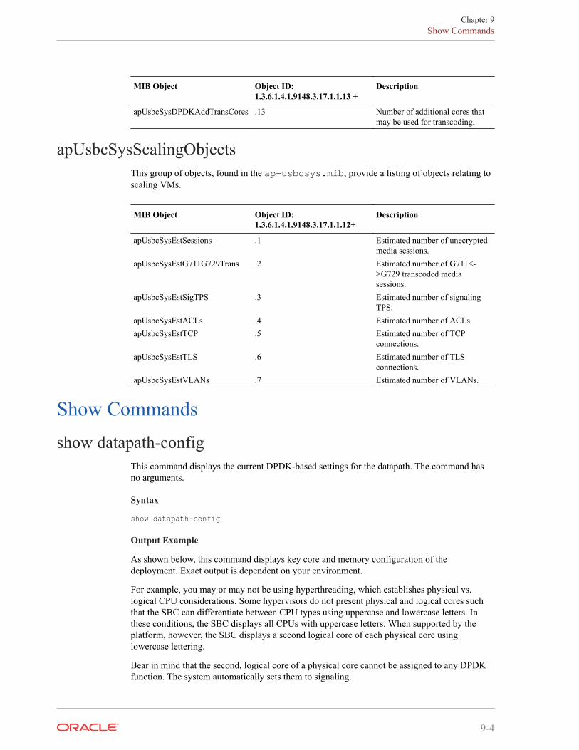
apUsbcSysScalingObjectsThis group of objects, found in the ap-usbcsys.mib, provide a listing of objects relating toscaling VMs.
MIB Object Object ID:1.3.6.1.4.1.9148.3.17.1.1.12+
Description
apUsbcSysEstSessions .1 Estimated number of unecryptedmedia sessions.
apUsbcSysEstG711G729Trans .2 Estimated number of G711<->G729 transcoded mediasessions.
apUsbcSysEstSigTPS .3 Estimated number of signalingTPS.
apUsbcSysEstACLs .4 Estimated number of ACLs.apUsbcSysEstTCP .5 Estimated number of TCP
connections.apUsbcSysEstTLS .6 Estimated number of TLS
connections.apUsbcSysEstVLANs .7 Estimated number of VLANs.
Show Commandsshow datapath-config
This command displays the current DPDK-based settings for the datapath. The command hasno arguments.
Syntax
show datapath-config
Output Example
As shown below, this command displays key core and memory configuration of thedeployment. Exact output is dependent on your environment.
For example, you may or may not be using hyperthreading, which establishes physical vs.logical CPU considerations. Some hypervisors do not present physical and logical cores suchthat the SBC can differentiate between CPU types using uppercase and lowercase letters. Inthese conditions, the SBC displays all CPUs with uppercase letters. When supported by theplatform, however, the SBC displays a second logical core of each physical core usinglowercase lettering.
Bear in mind that the second, logical core of a physical core cannot be assigned to any DPDKfunction. The system automatically sets them to signaling.
Chapter 9Show Commands
9-4
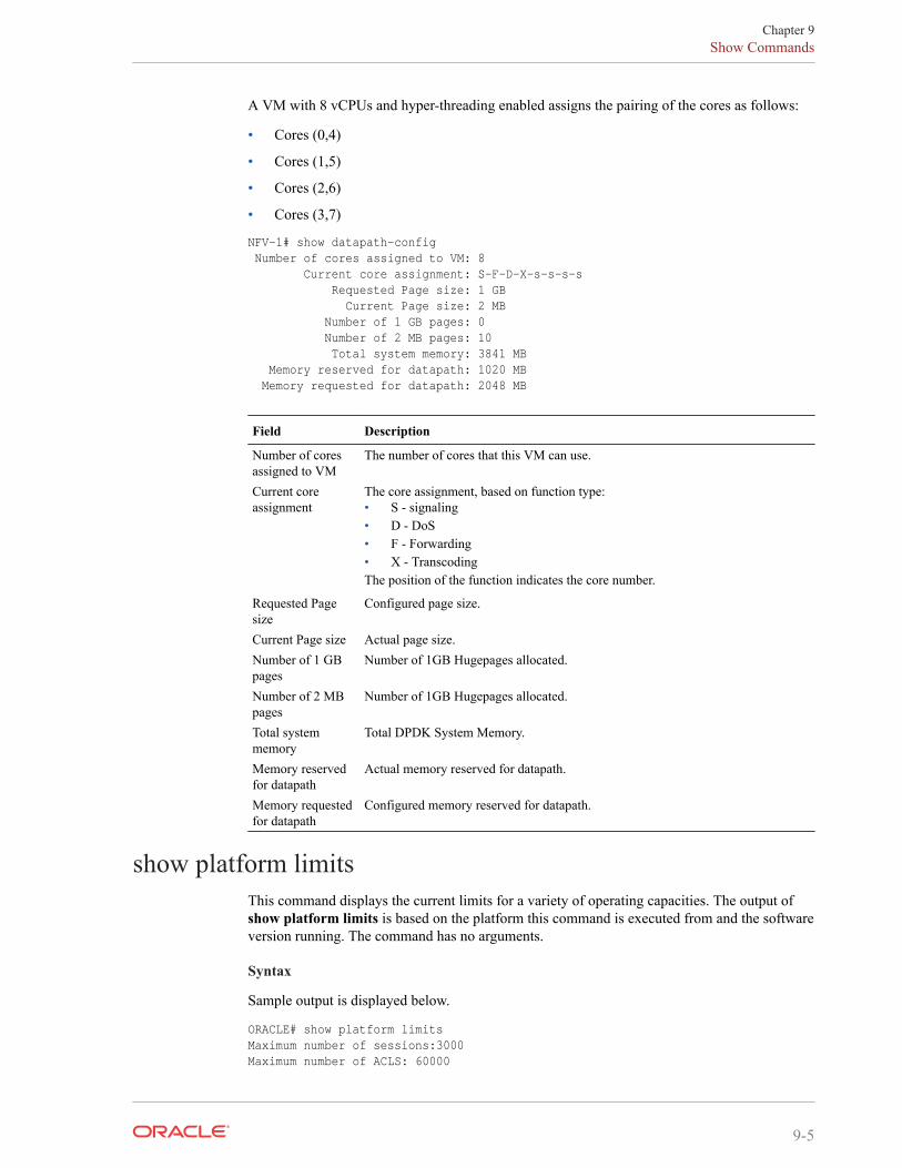
A VM with 8 vCPUs and hyper-threading enabled assigns the pairing of the cores as follows:
• Cores (0,4)
• Cores (1,5)
• Cores (2,6)
• Cores (3,7)
NFV-1# show datapath-config Number of cores assigned to VM: 8 Current core assignment: S-F-D-X-s-s-s-s Requested Page size: 1 GB Current Page size: 2 MB Number of 1 GB pages: 0 Number of 2 MB pages: 10 Total system memory: 3841 MB Memory reserved for datapath: 1020 MB Memory requested for datapath: 2048 MB
Field Description
Number of coresassigned to VM
The number of cores that this VM can use.
Current coreassignment
The core assignment, based on function type:• S - signaling• D - DoS• F - Forwarding• X - TranscodingThe position of the function indicates the core number.
Requested Pagesize
Configured page size.
Current Page size Actual page size.Number of 1 GBpages
Number of 1GB Hugepages allocated.
Number of 2 MBpages
Number of 1GB Hugepages allocated.
Total systemmemory
Total DPDK System Memory.
Memory reservedfor datapath
Actual memory reserved for datapath.
Memory requestedfor datapath
Configured memory reserved for datapath.
show platform limitsThis command displays the current limits for a variety of operating capacities. The output ofshow platform limits is based on the platform this command is executed from and the softwareversion running. The command has no arguments.
Syntax
Sample output is displayed below.
ORACLE# show platform limits Maximum number of sessions:3000 Maximum number of ACLS: 60000
Chapter 9Show Commands
9-5
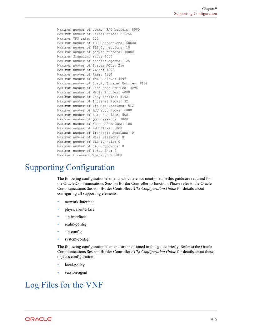
Maximum number of common PAC buffers: 8000 Maximum number of kernel-rules: 216256 Maximum CPS rate: 300 Maximum number of TCP Connections: 60000 Maximum number of TLS Connections: 10 Maximum number of packet buffers: 30000 Maximum Signaling rate: 4000 Maximum number of session agents: 125 Maximum number of System ACLs: 256 Maximum number of VLANs: 4096 Maximum number of ARPs: 4104 Maximum number of INTFC Flows: 4096 Maximum number of Static Trusted Entries: 8192 Maximum number of Untrusted Entries: 4096 Maximum number of Media Entries: 6000 Maximum number of Deny Entries: 8192 Maximum number of Internal Flows: 32 Maximum number of Sip Rec Sessions: 512 Maximum number of RFC 2833 Flows: 6000 Maximum number of SRTP Sessions: 500 Maximum number of QoS Sessions: 3000 Maximum number of Xcoded Sessions: 100 Maximum number of HMU Flows: 6000 Maximum number of Transport Sessions: 0 Maximum number of MSRP Sessions: 0 Maximum number of SLB Tunnels: 0 Maximum number of SLB Endpoints: 0 Maximum number of IPSec SAs: 0 Maximum Licensed Capacity: 256000
Supporting ConfigurationThe following configuration elements which are not mentioned in this guide are required forthe Oracle Communications Session Border Controller to function. Please refer to the OracleCommunications Session Border Controller ACLI Configuration Guide for details aboutconfiguring all supporting elements.
• network-interface
• physical-interface
• sip-interface
• realm-config
• sip-config
• system-config
The following configuration elements are mentioned in this guide briefly. Refer to the OracleCommunications Session Border Controller ACLI Configuration Guide for details about theseobject's configuration:
• local-policy
• session-agent
Log Files for the VNF
Chapter 9Supporting Configuration
9-6

The following log files capture log messaging related to VNF:
• log.usdp - Contains DPDK processing log messages.
• log.usdpClient - Contains log messages related to overall system.
Refer to Oracle Support personnel for details on working with these files and their content.
Chapter 9Log Files for the VNF
9-7
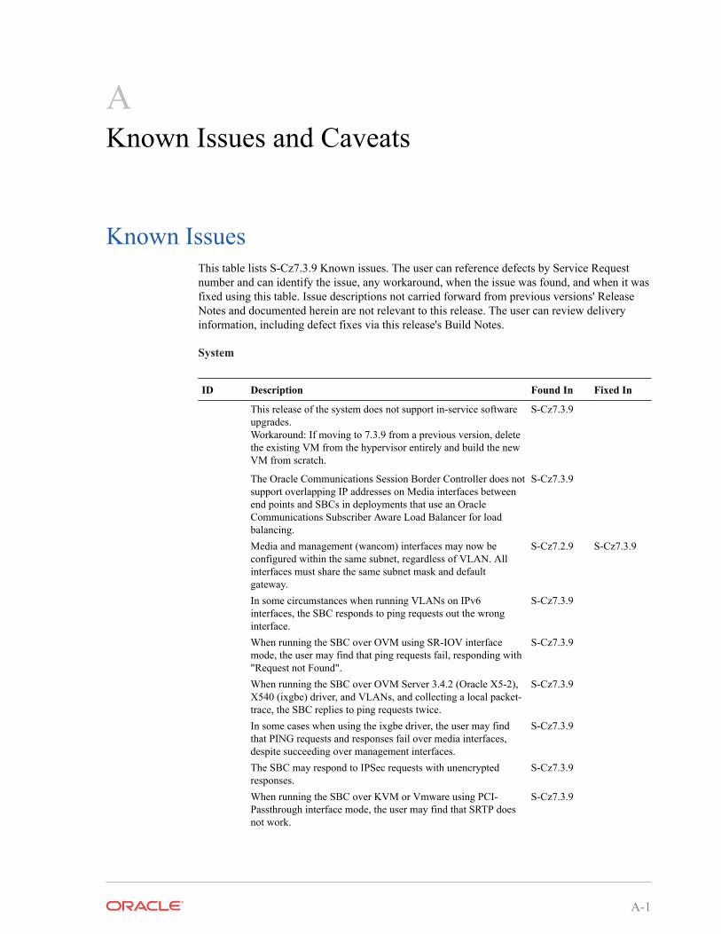
AKnown Issues and Caveats
Known IssuesThis table lists S-Cz7.3.9 Known issues. The user can reference defects by Service Requestnumber and can identify the issue, any workaround, when the issue was found, and when it wasfixed using this table. Issue descriptions not carried forward from previous versions' ReleaseNotes and documented herein are not relevant to this release. The user can review deliveryinformation, including defect fixes via this release's Build Notes.
System
ID Description Found In Fixed In
This release of the system does not support in-service softwareupgrades.Workaround: If moving to 7.3.9 from a previous version, deletethe existing VM from the hypervisor entirely and build the newVM from scratch.
S-Cz7.3.9
The Oracle Communications Session Border Controller does notsupport overlapping IP addresses on Media interfaces betweenend points and SBCs in deployments that use an OracleCommunications Subscriber Aware Load Balancer for loadbalancing.
S-Cz7.3.9
Media and management (wancom) interfaces may now beconfigured within the same subnet, regardless of VLAN. Allinterfaces must share the same subnet mask and defaultgateway.
S-Cz7.2.9 S-Cz7.3.9
In some circumstances when running VLANs on IPv6interfaces, the SBC responds to ping requests out the wronginterface.
S-Cz7.3.9
When running the SBC over OVM using SR-IOV interfacemode, the user may find that ping requests fail, responding with"Request not Found".
S-Cz7.3.9
When running the SBC over OVM Server 3.4.2 (Oracle X5-2),X540 (ixgbe) driver, and VLANs, and collecting a local packet-trace, the SBC replies to ping requests twice.
S-Cz7.3.9
In some cases when using the ixgbe driver, the user may findthat PING requests and responses fail over media interfaces,despite succeeding over management interfaces.
S-Cz7.3.9
The SBC may respond to IPSec requests with unencryptedresponses.
S-Cz7.3.9
When running the SBC over KVM or Vmware using PCI-Passthrough interface mode, the user may find that SRTP doesnot work.
S-Cz7.3.9
A-1
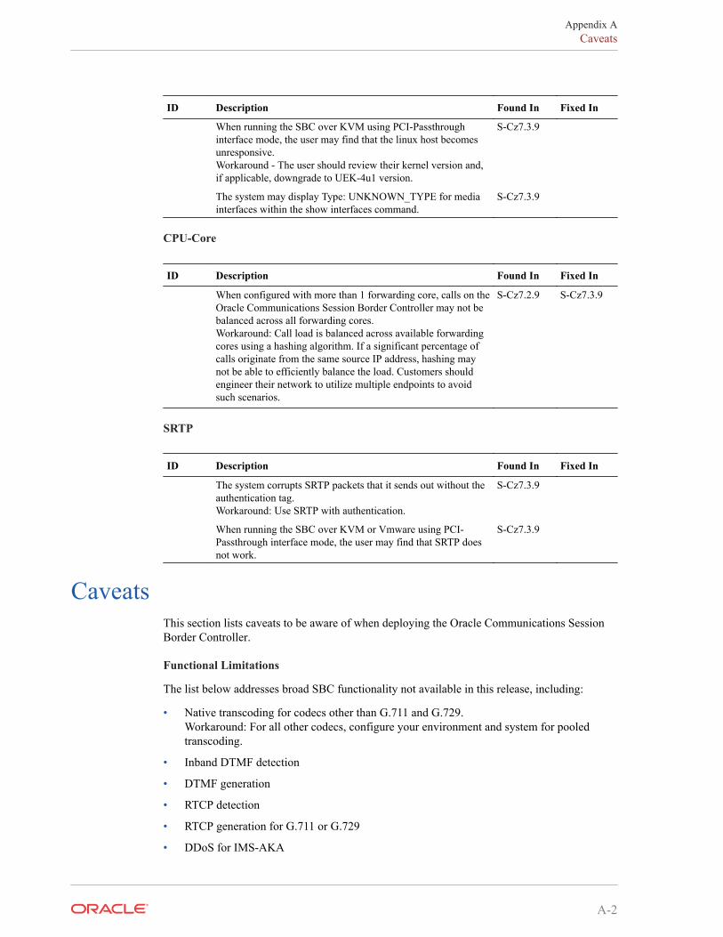
ID Description Found In Fixed In
When running the SBC over KVM using PCI-Passthroughinterface mode, the user may find that the linux host becomesunresponsive.Workaround - The user should review their kernel version and,if applicable, downgrade to UEK-4u1 version.
S-Cz7.3.9
The system may display Type: UNKNOWN_TYPE for mediainterfaces within the show interfaces command.
S-Cz7.3.9
CPU-Core
ID Description Found In Fixed In
When configured with more than 1 forwarding core, calls on theOracle Communications Session Border Controller may not bebalanced across all forwarding cores.Workaround: Call load is balanced across available forwardingcores using a hashing algorithm. If a significant percentage ofcalls originate from the same source IP address, hashing maynot be able to efficiently balance the load. Customers shouldengineer their network to utilize multiple endpoints to avoidsuch scenarios.
S-Cz7.2.9 S-Cz7.3.9
SRTP
ID Description Found In Fixed In
The system corrupts SRTP packets that it sends out without theauthentication tag.Workaround: Use SRTP with authentication.
S-Cz7.3.9
When running the SBC over KVM or Vmware using PCI-Passthrough interface mode, the user may find that SRTP doesnot work.
S-Cz7.3.9
CaveatsThis section lists caveats to be aware of when deploying the Oracle Communications SessionBorder Controller.
Functional Limitations
The list below addresses broad SBC functionality not available in this release, including:
• Native transcoding for codecs other than G.711 and G.729.Workaround: For all other codecs, configure your environment and system for pooledtranscoding.
• Inband DTMF detection
• DTMF generation
• RTCP detection
• RTCP generation for G.711 or G.729
• DDoS for IMS-AKA
Appendix ACaveats
A-2
• MSRP functionality
• TSCF functionality
• H.323 signaling or H.323-SIP inter-working
• In-service software upgrades for KVM and OVM deployments
• The SIP Monitor & Trace and WebGUI features are unsupported. Ensure that the system>web-server-config> state- parameter is set to disabled.
General Caveats
This section lists functional caveats applicable to this release.
• This release of the system does not support the following IPSec components:
– IKEv1
– Authentication header (AH)
– The AES-XCBC authentication algorithm
– Dynamic reconfiguration of security-associations
– Hitless HA failover of IPSec connections.
• The OVM server 3.4.2 does not support the virtual back-end required for para-virtualized(PV) networking. VIF emulated interfaces are supported but have lower performance.Consider using SR-IOV or PCI-passthru as an alternative if higher performance isrequired.
• Default levels for scalability and are set to ensure appropriate throttling based on platformcapacity factors such as hypervisor type, number and role of CPU cores, available hostmemory and I/O bandwidth. In some cases, those defaults may not be appropriate andthrottling may occur at lower or higher call rates than expected. Please contact OracleTechnical Support for details on how to override the default throttles, if required.
• To support HA failover, MAC anti-spoofing must be disabled for media interfaces on thehost hypervisor/vSwitch/SR-IOV_PF.
• For the Netra X5-2, the VNF currently only supports the X710 in the onboard slot forManagement and HA and the 82599 in the expansion slot, when using KVM. This is akernel defect; the user can monitor the kernel errata to uplift this fix when it becomesavailable.
• Attempting to use more than 6 cores for more than ~26k sessions results in RX bufferleaks. If this traffic rate persists, buffers become exhausted and the system crashes.
Upgrade Caveat
When upgrading from S-CZ7.3.9p3 (or earlier) to S-CZ7.3.9p4 or later, you must also updatethe target release's companion stage 3 bootloader.
Appendix ACaveats
A-3
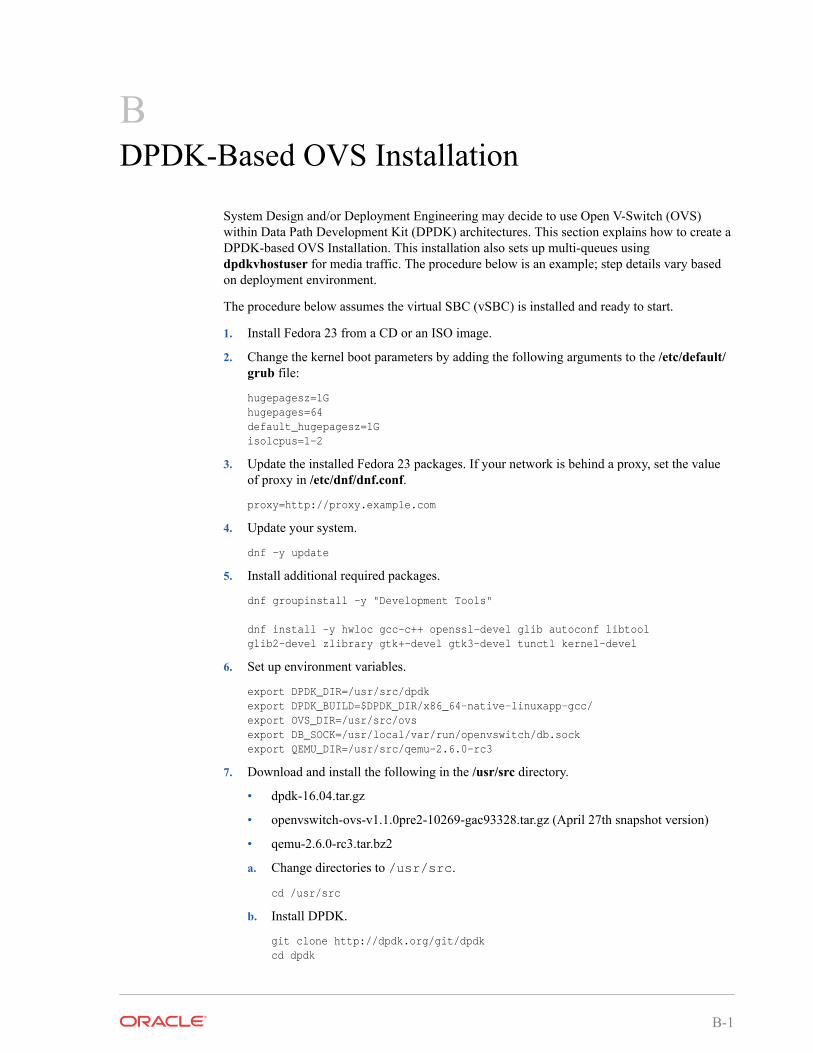
BDPDK-Based OVS Installation
System Design and/or Deployment Engineering may decide to use Open V-Switch (OVS)within Data Path Development Kit (DPDK) architectures. This section explains how to create aDPDK-based OVS Installation. This installation also sets up multi-queues usingdpdkvhostuser for media traffic. The procedure below is an example; step details vary basedon deployment environment.
The procedure below assumes the virtual SBC (vSBC) is installed and ready to start.
1. Install Fedora 23 from a CD or an ISO image.
2. Change the kernel boot parameters by adding the following arguments to the /etc/default/grub file:
hugepagesz=1Ghugepages=64default_hugepagesz=1Gisolcpus=1-2
3. Update the installed Fedora 23 packages. If your network is behind a proxy, set the valueof proxy in /etc/dnf/dnf.conf.
proxy=http://proxy.example.com
4. Update your system.
dnf -y update
5. Install additional required packages.
dnf groupinstall -y "Development Tools"
dnf install -y hwloc gcc-c++ openssl-devel glib autoconf libtoolglib2-devel zlibrary gtk+-devel gtk3-devel tunctl kernel-devel
6. Set up environment variables.
export DPDK_DIR=/usr/src/dpdkexport DPDK_BUILD=$DPDK_DIR/x86_64-native-linuxapp-gcc/export OVS_DIR=/usr/src/ovsexport DB_SOCK=/usr/local/var/run/openvswitch/db.sockexport QEMU_DIR=/usr/src/qemu-2.6.0-rc3
7. Download and install the following in the /usr/src directory.
• dpdk-16.04.tar.gz
• openvswitch-ovs-v1.1.0pre2-10269-gac93328.tar.gz (April 27th snapshot version)
• qemu-2.6.0-rc3.tar.bz2
a. Change directories to /usr/src.
cd /usr/src
b. Install DPDK.
git clone http://dpdk.org/git/dpdkcd dpdk
B-1
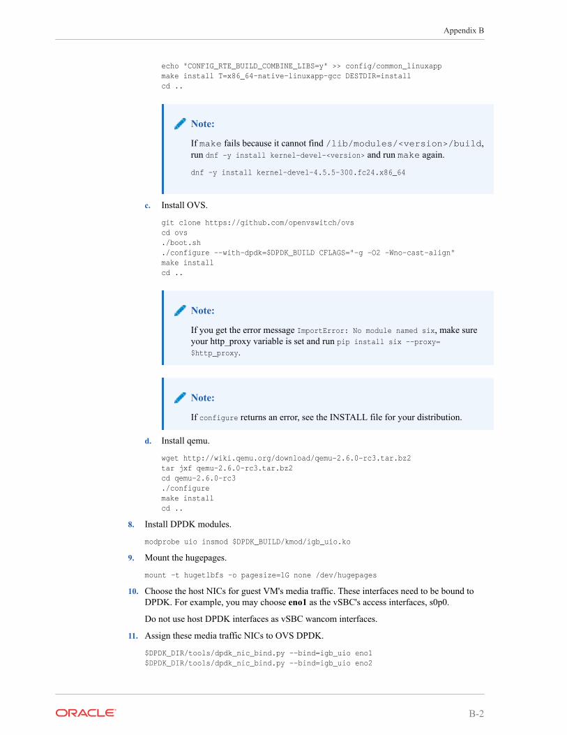
echo "CONFIG_RTE_BUILD_COMBINE_LIBS=y" >> config/common_linuxappmake install T=x86_64-native-linuxapp-gcc DESTDIR=installcd ..
Note:
If make fails because it cannot find /lib/modules/<version>/build,run dnf -y install kernel-devel-<version> and run make again.
dnf -y install kernel-devel-4.5.5-300.fc24.x86_64
c. Install OVS.
git clone https://github.com/openvswitch/ovscd ovs./boot.sh./configure --with-dpdk=$DPDK_BUILD CFLAGS="-g -O2 -Wno-cast-align"make installcd ..
Note:
If you get the error message ImportError: No module named six, make sureyour http_proxy variable is set and run pip install six --proxy=$http_proxy.
Note:
If configure returns an error, see the INSTALL file for your distribution.
d. Install qemu.
wget http://wiki.qemu.org/download/qemu-2.6.0-rc3.tar.bz2tar jxf qemu-2.6.0-rc3.tar.bz2cd qemu-2.6.0-rc3./configuremake installcd ..
8. Install DPDK modules.
modprobe uio insmod $DPDK_BUILD/kmod/igb_uio.ko
9. Mount the hugepages.
mount -t hugetlbfs -o pagesize=1G none /dev/hugepages
10. Choose the host NICs for guest VM's media traffic. These interfaces need to be bound toDPDK. For example, you may choose eno1 as the vSBC's access interfaces, s0p0.
Do not use host DPDK interfaces as vSBC wancom interfaces.
11. Assign these media traffic NICs to OVS DPDK.
$DPDK_DIR/tools/dpdk_nic_bind.py --bind=igb_uio eno1$DPDK_DIR/tools/dpdk_nic_bind.py --bind=igb_uio eno2
Appendix B
B-2
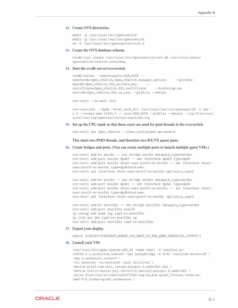
12. Create OVS directories.
mkdir -p /usr/local/etc/openvswitchmkdir -p /usr/local/var/run/openvswitchrm -f /usr/local/etc/openvswitch/conf.d
13. Create the OVS database schema.
ovsdb-tool create /usr/local/etc/openvswitch/conf.db /usr/local/share/openvswitch/vswitch.ovsschema
14. Start the ovsdb server/ovsvswitch.
ovsdb-server --remote=punix:$DB_SOCK --remote=db:Open_vSwitch,Open_vSwitch,manager_options --private-key=db:Open_vSwitch,SSL,private_key --certificate=Open_vSwitch,SSL,certificate --bootstrap-ca-cert=db:Open_vSwitch,SSL,ca_cert --pidfile --detach
ovs-vsctl --no-wait init
ovs-vswitchd --dpdk -vhost_sock_dir /usr/local/var/run/openvswitch -c 0xe -n 4 --socket-mem 16384,0 -- unix:$DB_SOCK --pidfile --detach --log-file=/usr/local/var/log/openvswitch/ovs-vswitchd.log
15. Set up the CPU mask so that these cores are used for pmd threads in the ovsvswitch.
ovs-vsctl set Open_vSwitch . other_config:pmd-cpu-mask=6
This starts two PMD threads, and therefore two RX/TX queue pairs.
16. Create bridges and ports. (You can create multiple ports to launch multiple guest VMs.)
ovs-vsctl add-br eno1br -- set bridge eno1br datapath_type=netdevovs-vsctl add-port eno1br dpdk0 -- set Interface dpdk0 type=dpdkovs-vsctl add-port eno1br vhost-user-port0-on-eno1br -- set Interface vhost-user-port0-on-eno1br type=dpdkvhostuserovs-vsctl set Interface vhost-user-port0-on-eno1br options:n_rxq=2
ovs-vsctl add-br eno2br -- set bridge eno2br datapath_type=netdevovs-vsctl add-port eno2br dpdk1 -- set Interface dpdk1 type=dpdkovs-vsctl add-port eno2br vhost-user-port0-on-eno2br -- set Interface vhost-user-port0-on-eno2br type=dpdkvhostuserovs-vsctl set Interface vhost-user-port0-on-eno2br options:n_rxq=2
ovs-vsctl add-br ens1f2br -- set bridge ens1f2br datapath_type=netdevovs-vsctl add-port ens1f2br ens1f2ip tuntap add mode tap tap0-on-ens1f2brip link set dev tap0-on-ens1f2br up ovs-vsctl add-port ens1f2br tap0-on-ens1f2br
17. Export your display.
export DISPLAY=IPADDRESS_WHERE_YOU_WANT_TO_SEE_QEMU_GRAPHICAL_OUTPUT:1
18. Launch your VM.
/usr/local/bin/qemu-system-x86_64 -name vsbc1 -S -machine pc-i440fx-2.1,accel=kvm,usb=off -cpu SandyBridge -m 8192 -realtime mlock=off \-smp 4,sockets=1,cores=4 \-rtc base=utc -no-shutdown -boot strict=on \-device piix3-usb-uhci,id=usb,bus=pci.0,addr=0x1.0x2 \-device virtio-serial-pci,id=virtio-serial0,bus=pci.0,addr=0x5 \-drive file=/usr/src/vms/nnSCZ739a6-img-vm_kvm.qcow2,if=none,id=drive-ide0-0-0,format=qcow2,cache=none \
Appendix B
B-3
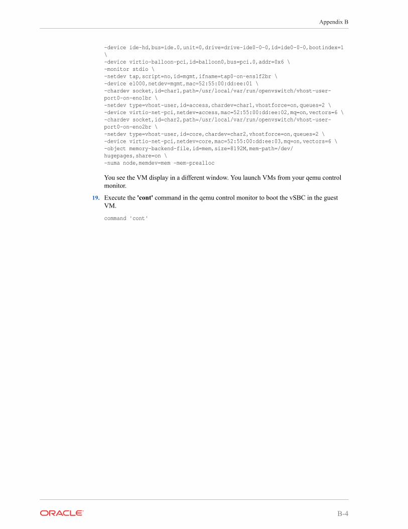
-device ide-hd,bus=ide.0,unit=0,drive=drive-ide0-0-0,id=ide0-0-0,bootindex=1 \-device virtio-balloon-pci,id=balloon0,bus=pci.0,addr=0x6 \-monitor stdio \-netdev tap,script=no,id=mgmt,ifname=tap0-on-ens1f2br \-device e1000,netdev=mgmt,mac=52:55:00:dd:ee:01 \-chardev socket,id=char1,path=/usr/local/var/run/openvswitch/vhost-user-port0-on-eno1br \-netdev type=vhost-user,id=access,chardev=char1,vhostforce=on,queues=2 \-device virtio-net-pci,netdev=access,mac=52:55:00:dd:ee:02,mq=on,vectors=6 \-chardev socket,id=char2,path=/usr/local/var/run/openvswitch/vhost-user-port0-on-eno2br \-netdev type=vhost-user,id=core,chardev=char2,vhostforce=on,queues=2 \-device virtio-net-pci,netdev=core,mac=52:55:00:dd:ee:03,mq=on,vectors=6 \-object memory-backend-file,id=mem,size=8192M,mem-path=/dev/hugepages,share=on \-numa node,memdev=mem -mem-prealloc
You see the VM display in a different window. You launch VMs from your qemu controlmonitor.
19. Execute the 'cont' command in the qemu control monitor to boot the vSBC in the guestVM.
command 'cont'
Appendix B
B-4