Embed Size (px)
DESCRIPTION
O & M manual for PUMPS etc
Citation preview
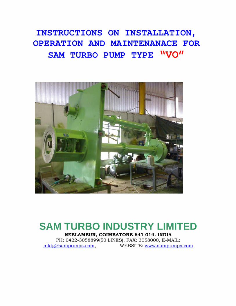
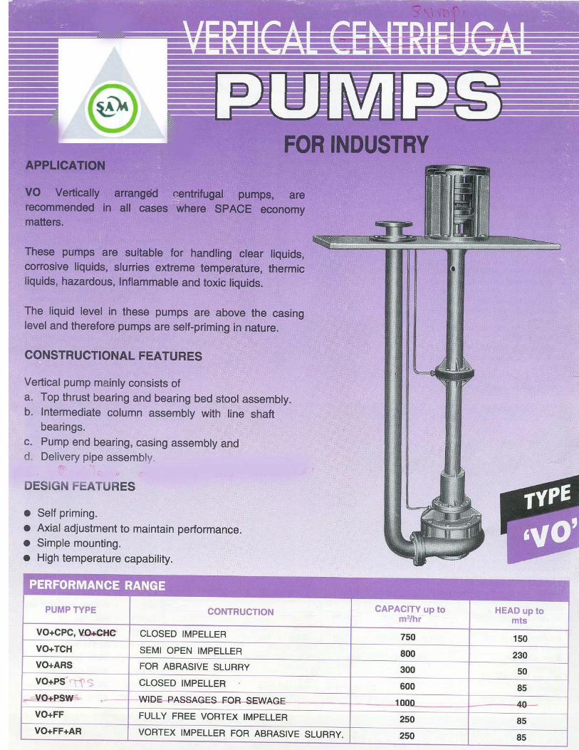
INSTRUCTIONS ON INSTALLATION, OPERATION AND MAINTENANACE FOR
SAM TURBO PUMP TYPE “VO”
SAM TURBO INDUSTRY LIMITED NEELAMBUR, COIMBATORE-641 014. INDIA
PH: 0422-3058899(50 LINES), FAX: 3058000, E-MAIL: [email protected], WEBSITE: www.sampumps.com
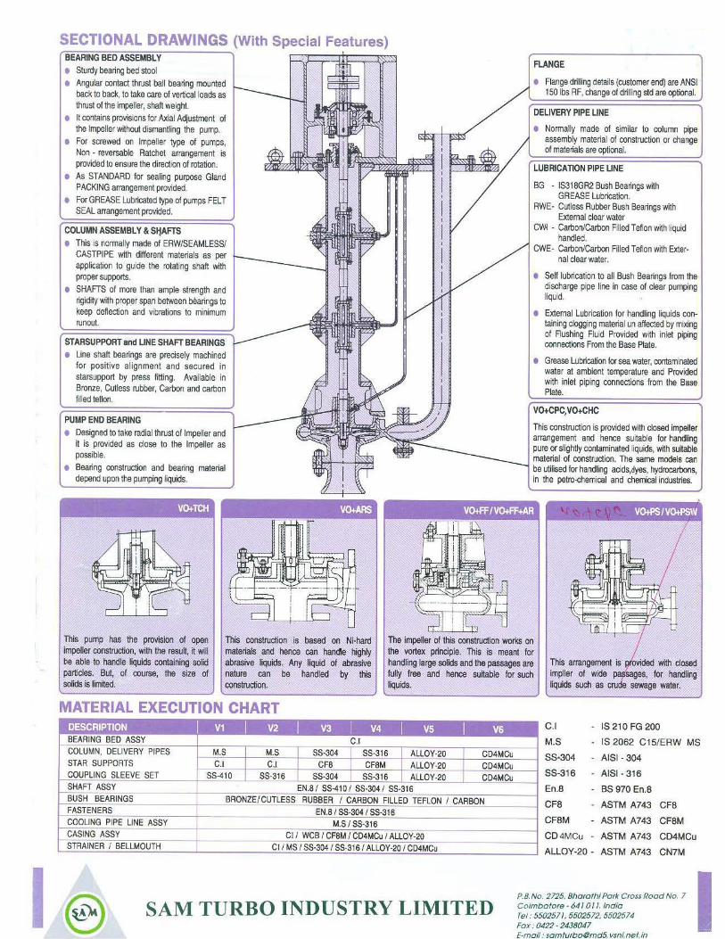
FOREWORD AND GUARANTEE: This erection and operation manual should be read in all cases by the fitters before erection and start up. We are not liable for the damage incurred due to failure to observe the instructions for erection and operation. During the period of guarantee, repair work should be done by our fitters only or should get our approval in writing before attending to the complaint themselves. Contrary to our acknowledgement of order if you use the pumps for a different service please get our concurrence. Otherwise, the guarantee for the pump will not apply. TYPES OF PUMPS: “VO & VR”, is the Vertical version of Sam’s standard Horizontal pumps CHC, CH.FF, FF+AR, AR,PS and PSW. VO: Pump shaft supported in sleeve type bearing for wet pit installation with liquid Lubrication. VR: Pump Shaft supported in metallic Ball & Roller bearings with grease lubrication for dry pit only. FOUR CHOICES OF LUBRICATION ARRANGEMENT Four choices of sleeve type Bearings and lubrication arrangement offered to meet duty requirements depending on the liquid in case of “VO” type pumps and they are designated as:- a. VO + BG : Bronze Bush Bearings with Grease lubrication arrangement. b. VO + C/TW: Carbon / Teflon Bush bearing arrangement with external water/ steam
lubrication. c. VO + C/ Tld: Carbon / Teflon Bush bearing arrangement with lubrication by the liquid handled. d. VO + RW : Rubber bush bearing arrangement with lubrications of external water under pressure. Check up from name plate of the pump model received by you and its lubrication arrangement. This is very important.
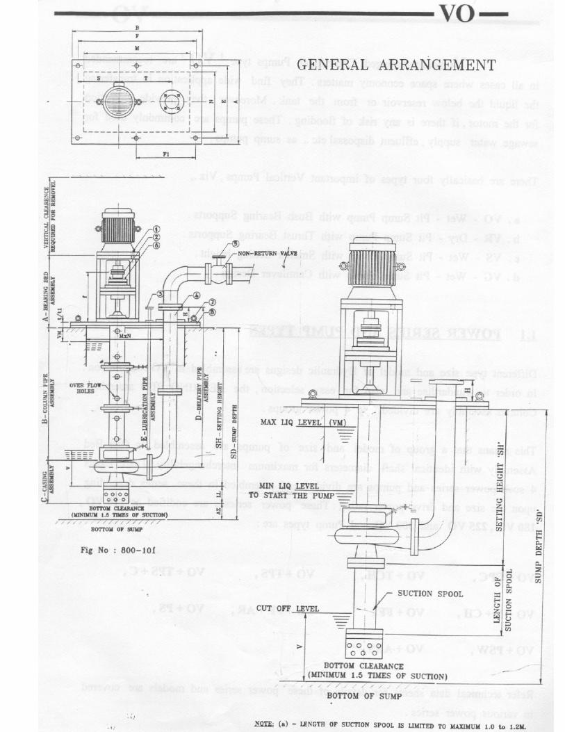
1. DESCRIPTION OF ARRANGEMENT: (Ref.Fig.No.810- M5. Page 19)
VO + BG: In case of sleeve type Bronze Bearings individual pipe lines are provided for supply
Grease to each sleeve type Bearings support from the top of sole plate itself.
NOTE: For pump above setting height of 5M, a Grease Pump driven by the main
pump is supplied along with the pump which feeds small quantity of grease
for all the Bearing through individual pipe lines.
MAINTENANCE OF GREASE PUMP:
Ensure that the Grease Reservoir is filled up always with sufficient quantity. In
the case of Reservoir is empty, the pump will fail. The quantity of grease feeding in
the grease pump. It is normally factory set.
Page 1 --------------
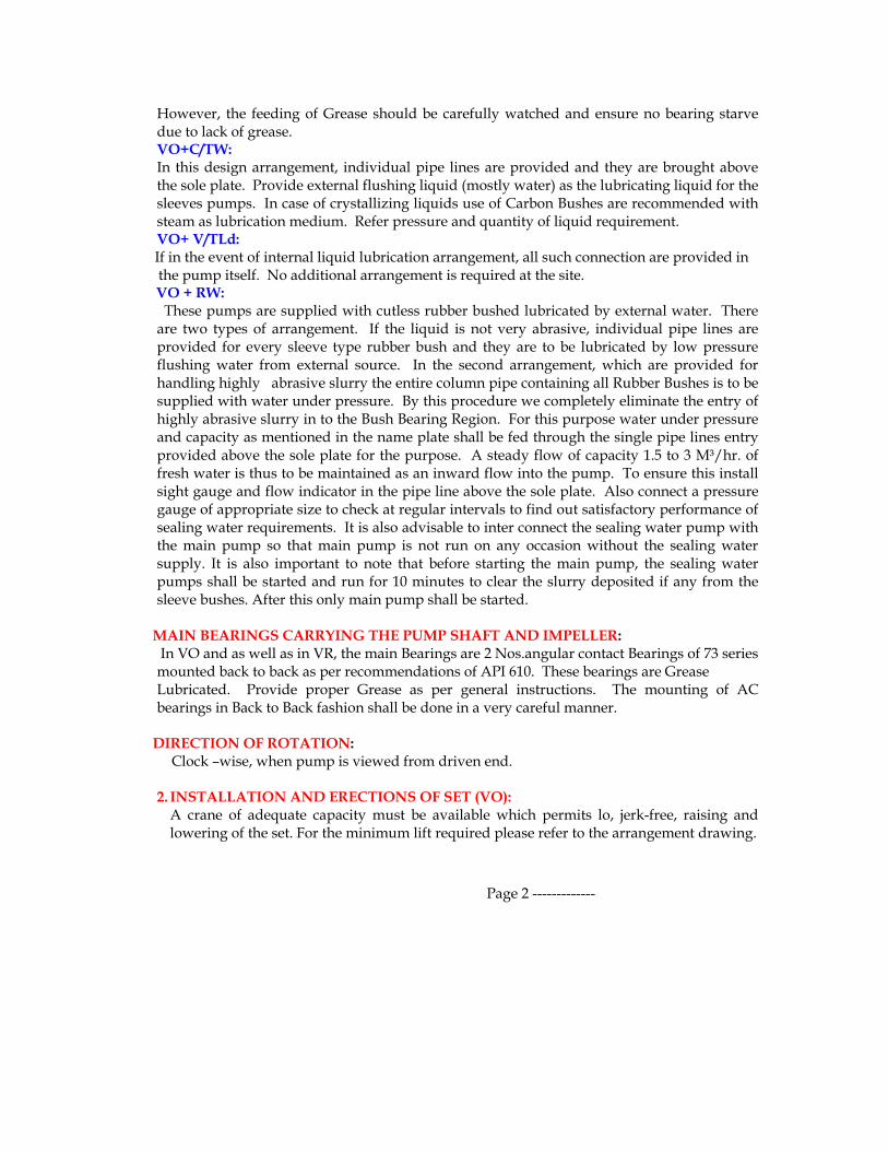
However, the feeding of Grease should be carefully watched and ensure no bearing starve due to lack of grease. VO+C/TW: In this design arrangement, individual pipe lines are provided and they are brought above the sole plate. Provide external flushing liquid (mostly water) as the lubricating liquid for the sleeves pumps. In case of crystallizing liquids use of Carbon Bushes are recommended with steam as lubrication medium. Refer pressure and quantity of liquid requirement. VO+ V/TLd:
If in the event of internal liquid lubrication arrangement, all such connection are provided in the pump itself. No additional arrangement is required at the site.
VO + RW: These pumps are supplied with cutless rubber bushed lubricated by external water. There are two types of arrangement. If the liquid is not very abrasive, individual pipe lines are provided for every sleeve type rubber bush and they are to be lubricated by low pressure flushing water from external source. In the second arrangement, which are provided for handling highly abrasive slurry the entire column pipe containing all Rubber Bushes is to be supplied with water under pressure. By this procedure we completely eliminate the entry of highly abrasive slurry in to the Bush Bearing Region. For this purpose water under pressure and capacity as mentioned in the name plate shall be fed through the single pipe lines entry provided above the sole plate for the purpose. A steady flow of capacity 1.5 to 3 M³/hr. of fresh water is thus to be maintained as an inward flow into the pump. To ensure this install sight gauge and flow indicator in the pipe line above the sole plate. Also connect a pressure gauge of appropriate size to check at regular intervals to find out satisfactory performance of sealing water requirements. It is also advisable to inter connect the sealing water pump with the main pump so that main pump is not run on any occasion without the sealing water supply. It is also important to note that before starting the main pump, the sealing water pumps shall be started and run for 10 minutes to clear the slurry deposited if any from the sleeve bushes. After this only main pump shall be started.
MAIN BEARINGS CARRYING THE PUMP SHAFT AND IMPELLER:
In VO and as well as in VR, the main Bearings are 2 Nos.angular contact Bearings of 73 series mounted back to back as per recommendations of API 610. These bearings are Grease Lubricated. Provide proper Grease as per general instructions. The mounting of AC bearings in Back to Back fashion shall be done in a very careful manner.
DIRECTION OF ROTATION: Clock –wise, when pump is viewed from driven end.
2. INSTALLATION AND ERECTIONS OF SET (VO):
A crane of adequate capacity must be available which permits lo, jerk-free, raising and lowering of the set. For the minimum lift required please refer to the arrangement drawing.
Page 2 -------------
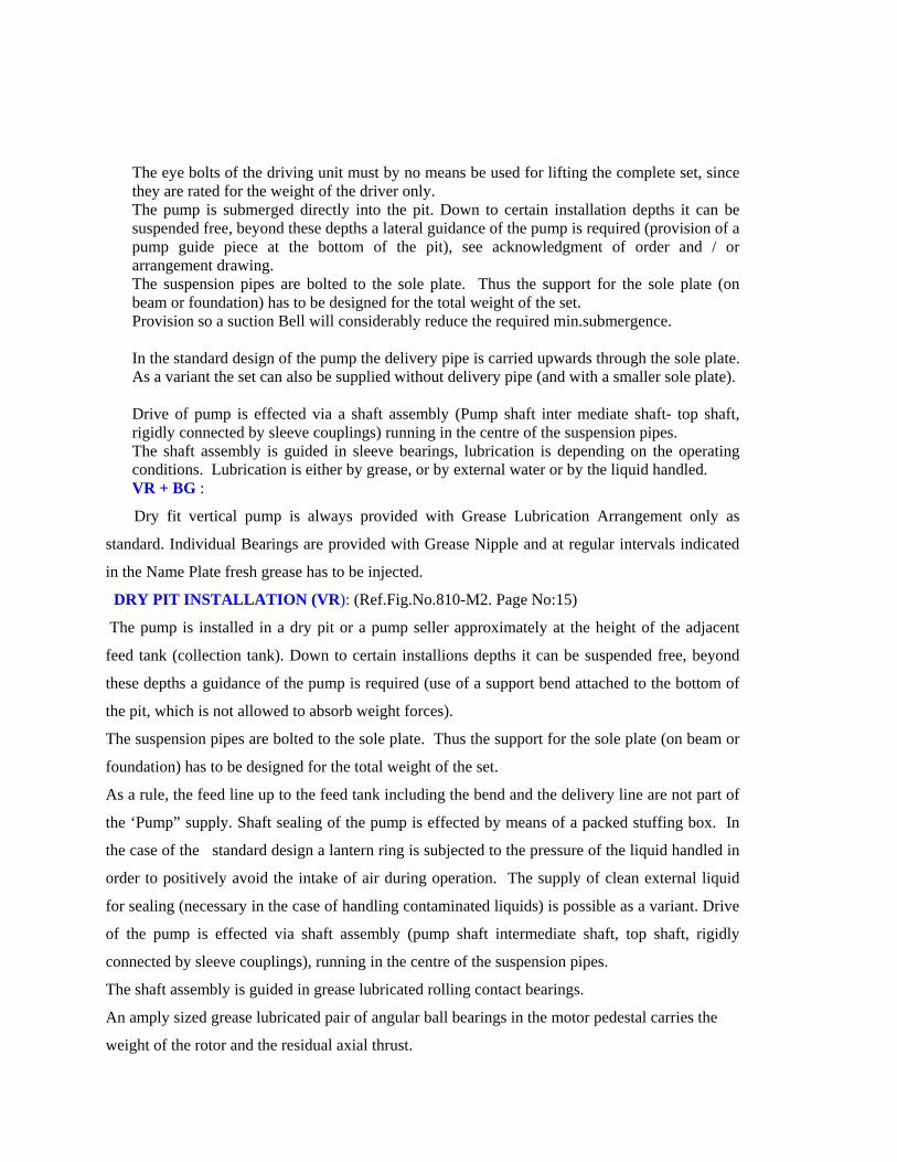
The eye bolts of the driving unit must by no means be used for lifting the complete set, since they are rated for the weight of the driver only. The pump is submerged directly into the pit. Down to certain installation depths it can be suspended free, beyond these depths a lateral guidance of the pump is required (provision of a pump guide piece at the bottom of the pit), see acknowledgment of order and / or arrangement drawing. The suspension pipes are bolted to the sole plate. Thus the support for the sole plate (on beam or foundation) has to be designed for the total weight of the set. Provision so a suction Bell will considerably reduce the required min.submergence. In the standard design of the pump the delivery pipe is carried upwards through the sole plate. As a variant the set can also be supplied without delivery pipe (and with a smaller sole plate). Drive of pump is effected via a shaft assembly (Pump shaft inter mediate shaft- top shaft, rigidly connected by sleeve couplings) running in the centre of the suspension pipes. The shaft assembly is guided in sleeve bearings, lubrication is depending on the operating conditions. Lubrication is either by grease, or by external water or by the liquid handled. VR + BG :
Dry fit vertical pump is always provided with Grease Lubrication Arrangement only as
standard. Individual Bearings are provided with Grease Nipple and at regular intervals indicated
in the Name Plate fresh grease has to be injected.
DRY PIT INSTALLATION (VR): (Ref.Fig.No.810-M2. Page No:15)
The pump is installed in a dry pit or a pump seller approximately at the height of the adjacent
feed tank (collection tank). Down to certain installions depths it can be suspended free, beyond
these depths a guidance of the pump is required (use of a support bend attached to the bottom of
the pit, which is not allowed to absorb weight forces).
The suspension pipes are bolted to the sole plate. Thus the support for the sole plate (on beam or
foundation) has to be designed for the total weight of the set.
As a rule, the feed line up to the feed tank including the bend and the delivery line are not part of
the ‘Pump” supply. Shaft sealing of the pump is effected by means of a packed stuffing box. In
the case of the standard design a lantern ring is subjected to the pressure of the liquid handled in
order to positively avoid the intake of air during operation. The supply of clean external liquid
for sealing (necessary in the case of handling contaminated liquids) is possible as a variant. Drive
of the pump is effected via shaft assembly (pump shaft intermediate shaft, top shaft, rigidly
connected by sleeve couplings), running in the centre of the suspension pipes.
The shaft assembly is guided in grease lubricated rolling contact bearings.
An amply sized grease lubricated pair of angular ball bearings in the motor pedestal carries the
weight of the rotor and the residual axial thrust.
2. Shafts.
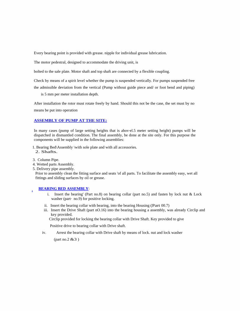
Every bearing point is provided with grease. nipple for individual grease lubrication.
The motor pedestral, designed to accommodate the driving unit, is
bolted to the sale plate. Motor shaft and top shaft are connected by a flexible coupling.
Check by means of a spirit level whether the pump is suspended vertically. For pumps suspended free
the admissible deviation from the vertical (Pump without guide piece and/ or foot bend and piping)
is 5 mm per meter installation depth.
After installation the rotor must rotate freely by hand. Should this not be the case, the set must by no
means be put into operation
ASSEMBLY OF PUMP AT THE SITE:
In many cases (pump of large setting heights that is abov·el.5 meter setting height) pumps will be dispatched in dismantled condition. The final assembly, be done at the site only. For this purpose the components will be supplied in the following assemblies:
1. Bearing Bed\Assembly \with sole plate and with all accessories.
Prior to assembly clean the fitting surface and seats 'of all parts. To facilitate the assembly easy, wet all fittings and sliding surfaces by oil or grease.
3. Column Pipe. 4. Wetted parts Assembly. 5. Delivery pipe assembly.
BEARING BED ASSEMBLY: .
i. Insert the bearing' (Part no.8) on bearing collar (part no.5) and fasten by lock nut & Lock washer (part· no.9) for positive locking.
ii. Insert the bearing collar with bearing, into the bearing Housing (Part 00.7) iii. Insert the Drive Shaft (part nO.16) into the bearing housing a assembly, was already Circlip and
key provided. Circlip provided for locking the bearing collar with Drive Shaft. Key provided to give
Positive drive to bearing collar with Drive shaft.
iv. Arrest the bearing collar with Drive shaft by means of lock. nut and lock washer
(part no.2 &3 )
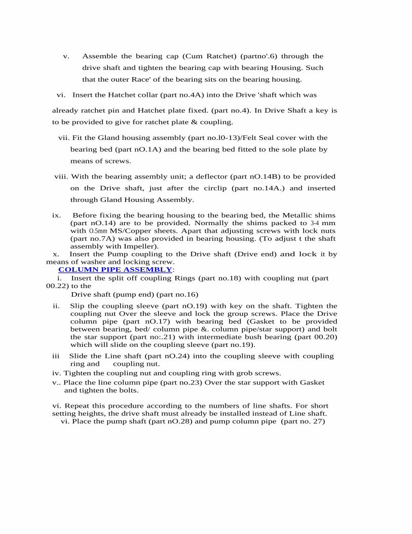
vi. Place the pump shaft (part nO.28) and pump column pipe (part no. 27)
v. Assemble the bearing cap (Cum Ratchet) (partno'.6) through the
drive shaft and tighten the bearing cap with bearing Housing. Such
that the outer Race' of the bearing sits on the bearing housing.
vi. Insert the Hatchet collar (part no.4A) into the Drive 'shaft which was
already ratchet pin and Hatchet plate fixed. (part no.4). In Drive Shaft a key is
to be provided to give for ratchet plate & coupling.
vii. Fit the Gland housing assembly (part no.l0-13)/Felt Seal cover with the
bearing bed (part nO.1A) and the bearing bed fitted to the sole plate by
means of screws.
viii. With the bearing assembly unit; a deflector (part nO.14B) to be provided
on the Drive shaft, just after the circlip (part no.14A.) and inserted
through Gland Housing Assembly.
ix. Before fixing the bearing housing to the bearing bed, the Metallic shims (part nO.14) are to be provided. Normally the shims packed to 3-4 mm with O.5mm MS/Copper sheets. Apart that adjusting screws with lock nuts (part no.7A) was also provided in bearing housing. (To adjust t the shaft assembly with Impeller).
x. Insert the Pump coupling to the Drive shaft (Drive end) and lock it by means of washer and locking screw.
COLUMN PIPE ASSEMBLY: i. Insert the split off coupling Rings (part no.18) with coupling nut (part 00.22) to the
Drive shaft (pump end) (part no.16)
ii. Slip the coupling sleeve (part nO.19) with key on the shaft. Tighten the coupling nut Over the sleeve and lock the group screws. Place the Drive column pipe (part nO.17) with bearing bed (Gasket to be provided between bearing, bed/ column pipe &. column pipe/star support) and bolt the star support (part no:.21) with intermediate bush bearing (part 00.20) which will slide on the coupling sleeve (part no.19).
iii Slide the Line shaft (part nO.24) into the coupling sleeve with coupling ring and coupling nut.
iv. Tighten the coupling nut and coupling ring with grob screws. v.. Place the line column pipe (part no.23) Over the star support with Gasket
and tighten the bolts.
vi. Repeat this procedure according to the numbers of line shafts. For short setting heights, the drive shaft must already be installed instead of Line shaft.
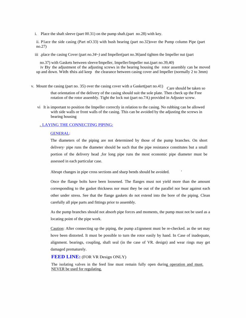
i. Place the shaft sleeve (part 00.31) on the pump shaft.(part no.28) with key.
ii. P1ace the side casing (Part nO.33) with bush bearing (part no.32)over the Pump column Pipe (part no.27)
iii .place the casing Cover (part no.34~) and Impeller(part no.36)and tighten the Impeller nut (part
no.37) with Gaskets between sleeve/Impeller, Impeller/Impeller nut.(part no.39,40) iv By the adjustment of the adjusting screws in the bearing housing the rotor assembly can be moved up and down. With this aid keep the clearance between casing cover and Impeller (normally 2 to 3mm)
Care should be taken so that orientation of the delivery of the casing should suit the sole plate. Then check up the Free rotation of the rotor assembly. Tight the lock nut (part no.7A) provided in Adjuster screw.
v. Mount the casing (part no. 35) over the casing cover with a Gasket(part no.41)
vi It is important to position the Impeller correctly in relation to the casing. No rubbing can be allowed
with side walls or front walls of the casing. This can be avoided by the adjusting the screws in bearing housing
. LAYING THE CONNECTING PlPING:
GENERAL:
The diameters of the piping are not determined by those of the pump branches. On short
delivery· pipe runs the diameter should be such that the pipe resistance constitutes but a small
portion of the delivery head ,for long pipe runs the most economic pipe diameter must be
assessed in each particular case.
Abrupt changes in pipe cross sections and sharp bends should be avoided. '
Once the flange bolts have been loosened. The flanges must not yield more than the amount
corresponding to the gasket thickness nor must they be out of the parallel nor bear against each
other under stress. See that the flange gaskets do not extend into the bore of the piping. Clean
carefully all pipe parts and fittings prior to assembly.
As the pump branches should not absorb pipe forces and moments, the pump must not be used as a
locating point of the pipe work.
Caution: After connecting up the piping, the pump a1ignment must be re-checked. as the set may
hove been distorted. It must be possible to turn the rotor easily by hand. In Case of inadequate,
alignment. bearings, coupling, shaft seal (in the case of VR. design) and wear rings may get
damaged prematurely.
FEED LINE: (FOR VR Design ONLY)
The isolating valves in the feed line must remain fully open during operation and must. NEVER be used for regulating.
DELIVERY ,LINE
Install a gate valve or, an .output control valve in the delivery line as close' to the pump branch as possible. As a matter .of principle, it is recommended to place i?- non-return valve between the pump branch and regulating valve, thus protecting the pump branch and regulating valve, thus protecting the pump against reverse rotation and water hammer which may occur in case of sudden shut-down.
STARTING - UP AND STOPPING:- PRECAUTIONS TO BE TAKEN BEFORE OPERATION
Packing of the stuffing Box (For YO + RW) design only. The pumps are delivered by us with the stuffing box unpacked. Cut the individual packing rings from the packing plait supplied to suitable length using a gauging plug of the same diameter as the shaft protecting sleeve.' The cut pieces. must not be too long.
A gap of I mm between the joints after fitting will, in any case, prove less detrimental than squeezing too long pieces together. When installing the packing rings the joints of two consecutive rings must be staggered. Sequence of installation of the packing rings and lantern ring :
I packing ring - lantern ring- 3. packing rings.
The gland must not be tightened too firmly because other-wise the packing and the shaft sleeve may get damaged. Make sure that the gland is no\ tightened unevenly and does not rub on the shaft sleeve the shaft must' turn easily by hand.
Lubrication of bearings by external water (fresh water) (for VO + R W design with external water lubrication only)
The sleeve bearings of the shaft assembly and the sleeve bearing' in the pump must not run dry. Thus the external water lubrication must be switched on before starting the set .. ,
CHECK OF DIRECTION OF ROTATION
The direction of rotation" must correspond to the direction arrow to the sole plate. For checking' the
direction of rotation the motor may be started for a MOMENT ONLY. It is always better to remove the
motor separately from the pump and check the direction of rotation.
STARTING -UP:
The regulating valve in the delivery line should be closed or, in the case of automatic operation, the
full back pressure should be on the non-return valve.
Once the pump has run· up to working speed, open the regulating valve in the delivery line slowly
until the required service data of the pump are reached. Prolonged operation against closed
regulating valve in thy delivery line may lead to destruction of the internal pump parts and must
therefore be avoided.
For YO (wet pit installation) see that the lowest admissible liquid level in the pit (minimum
submergence) is maintained during starting-up as well as during operation. The required minimum
submergence prevents vibration and thus damage to the set - which may occur: due to the formation
of air entraining vortices which may extend as far as the interior of the pump.
In case of VR (dry 'pit installation) tighten gland at first only slightly for running-in even if the leakage is greater. than what is normal. After a certain running-in' period the gland should be tightened evenly until there is only slight leakage from the stuffing box.
An alteration of the service data of the pump which might become necessary may be effected only, with the aid of the regulating valve in the delivery line.
Particular care should be taken that
a. The driver does not get overloaded if the specific weight of ·the liquid handled is greater than that originally provided. When starting-up automatically operated plants, all isolating valves, hence the delivery gate valve too, must be kept open.
STOPPING:
If there is no back-flow preventer (a 'swing' type or 'lift' type or other check valve) close the regulating valve in the delivery line. Do not switch off driver until then.
Close isolating valve in the feed line only if necessary.
RE-STARTING :
Before re-starting the set, take care that pump shaft does not rotate back rotating in opposite direction may lead to wards. Starting with the shaft damage.
NON-REVERSE RATCHET:
All vertical pumps are provided with Non –Reverse Ratchet arrangements. This prevents wrong directions of rotation.
SUPERVISI9N AND MA1NTENANCE OF THE INDIVIDUALLY LUBRICATED ROLLING CONTACT BEARINGS:
Bearings in the motor pedestal (for all, variants) Intermediate bearings for variant VRT (dry pit 1nstallation).
BEARING TEMPERATURE. The Bearing temperature must not exceed 80°C. RE-GREASING (INTERVALS).
Re-greasing, using a grease gun, through the grease nipples. During regreasing there is always the risk of dirt entering the bearing space. Care should be taken that grease container and greasing devices are clean and that -the lubricant will not be contaminated when transferred into another container.
Lubricating intervals at pump speed:
1500 1 / min. 1800 1 / min. 3000 1 / min.
Every 2500 Every 2000 Every 1500
Operating Operating Operating
Hours Hours Hours
Lubricating quantities – Lubricants:
When installing the rolling contact bearings with a fresh grease charge, the
Hollow spaces of the-rolling contact bearings shall always be completely filled with grease the housing space on both sides, however, only be filled one third.
If the bearings are over greased (too much grease in' the bearing) there is the danger of hot running.
As lubricating grease a lithium soap high quality bearing grease shall be used which is free from resins and acids and which shall have, a rust inhibiting effect. Grease properties
Consistency No. : 2 ( Work penetration : ( 265 -295)
Usable temperature: upto 100ºC Dropping point not below : 160ºC
SUPERVISION AND MAINTENANCE OF THE PACKED STUFFING BOX: FOR VRT DESIGN ONLY :
In order to dissipate the friction heat on the sealing surface a packed stuffing box must always drip slightly. Should, however, the leakage increase too much and should it not diminish when evenly tightening the gland, the packing must be renewed.
The installation of the new packing 1-sto be done 'with special attention to the following points:
a. The surface of the shaft protecting sleeve must be in perfect condition, otherwise the shaft ~protecting', sleeve must be changed.
b. The old packing must be completely' removed as otherwise' the running faces of the shaft protecting sleeve \will get damaged within short ti me in spite of the new packing.
c. The quality of the packing material used must suit the operating conditions.
DISMANTLING AND ASSEMBLING
If the set has been maintained and serviced carefully, breakdowns which necessary date the dis mantling should not occur. If, however" faults occur, the cause should be located before dismantling, if possible.
If technical persons are not available, we recommend that you request the service of an erection engineer or dispatch the set to, our works for checking.' If the set is being stripped by yourselves, all parts must be handled with greatest care, avoiding
blows and shocks
All parts must be carefully cleaned, tested for wear and, if necessary, reconditioned or replaced with new parts. '
When assembling the pump take into account the pump section drawing. After assembly, the rotor must turn easily by hand. Otherwise the bearings coupling, shaft' seal and wear rings opposite the impeller may get damaged prematurely.
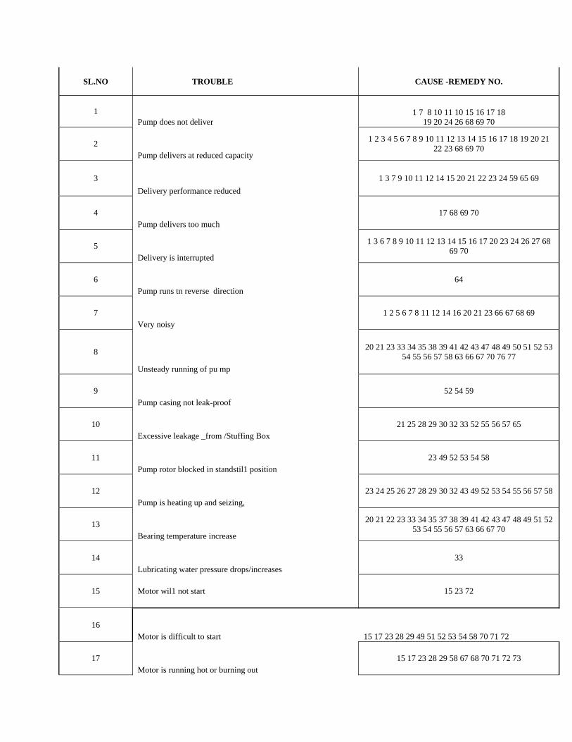
SL.NO TROUBLE CAUSE -REMEDY NO.
1 Pump does not deliver
1 7 8 10 11 10 15 16 17 18 19 20 24 26 68 69 70
2 Pump delivers at reduced capacity
1 2 3 4 5 6 7 8 9 10 11 12 13 14 15 16 17 18 19 20 21 22 23 68 69 70
3 Delivery performance reduced
1 3 7 9 10 11 12 14 15 20 21 22 23 24 59 65 69
4 Pump delivers too much
17 68 69 70
5 Delivery is interrupted
1 3 6 7 8 9 10 11 12 13 14 15 16 17 20 23 24 26 27 68 69 70
6 Pump runs tn reverse direction
64
7 Very noisy
1 2 5 6 7 8 11 12 14 16 20 21 23 66 67 68 69
8
Unsteady running of pu mp
20 21 23 33 34 35 38 39 41 42 43 47 48 49 50 51 52 53 54 55 56 57 58 63 66 67 70 76 77
9 Pump casing not leak-proof
52 54 59
10 Excessive leakage _from /Stuffing Box
21 25 28 29 30 32 33 52 55 56 57 65
11 Pump rotor blocked in standstil1 position
23 49 52 53 54 58
12 Pump is heating up and seizing,
23 24 25 26 27 28 29 30 32 43 49 52 53 54 55 56 57 58
13 Bearing temperature increase
20 21 22 23 33 34 35 37 38 39 41 42 43 47 48 49 51 52 53 54 55 56 57 63 66 67 70
14 Lubricating water pressure drops/increases
33
15 Motor wil1 not start 15 23 72
16 Motor is difficult to start 15 17 23 28 29 49 51 52 53 54 58 70 71 72
17 Motor is running hot or burning out
15 17 23 28 29 58 67 68 70 71 72 73
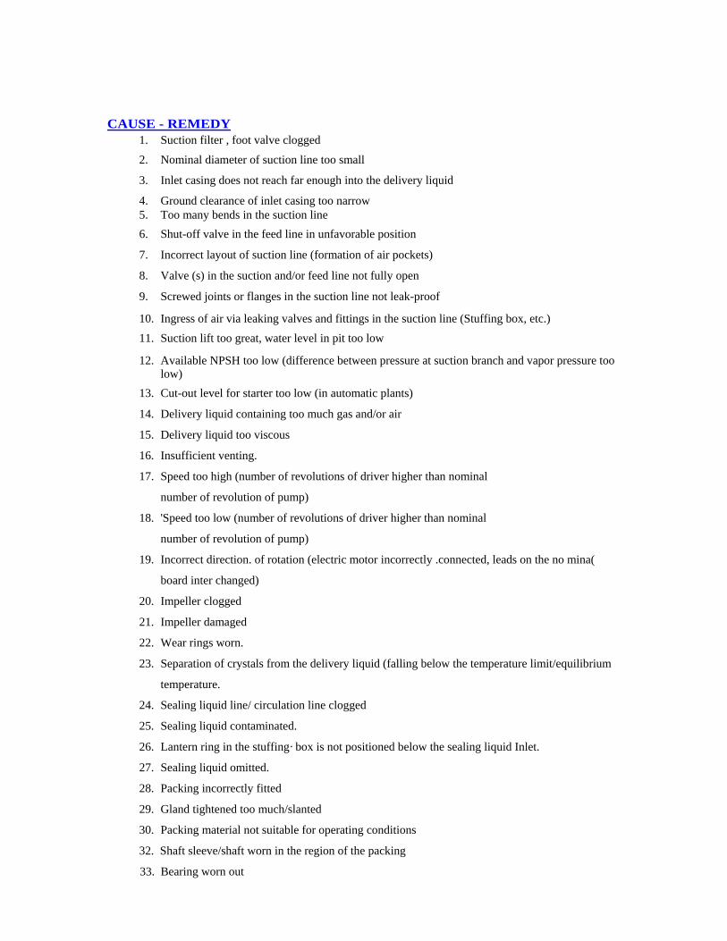
CAUSE - REMEDY
1. Suction filter , foot valve clogged
2. Nominal diameter of suction line too small
3. Inlet casing does not reach far enough into the delivery liquid
4. Ground clearance of inlet casing too narrow 5. Too many bends in the suction line 6. Shut-off valve in the feed line in unfavorable position
7. Incorrect layout of suction line (formation of air pockets)
8. Valve (s) in the suction and/or feed line not fully open
9. Screwed joints or flanges in the suction line not leak-proof
10. Ingress of air via leaking valves and fittings in the suction line (Stuffing box, etc.)
11. Suction lift too great, water level in pit too low
12. Available NPSH too low (difference between pressure at suction branch and vapor pressure too low)
13. Cut-out level for starter too low (in automatic plants)
14. Delivery liquid containing too much gas and/or air
15. Delivery liquid too viscous
16. Insufficient venting.
17. Speed too high (number of revolutions of driver higher than nominal
number of revolution of pump)
18. 'Speed too low (number of revolutions of driver higher than nominal
number of revolution of pump)
19. Incorrect direction. of rotation (electric motor incorrectly .connected, leads on the no mina(
board inter changed)
20. Impeller clogged
21. Impeller damaged
22. Wear rings worn.
23. Separation of crystals from the delivery liquid (falling below the temperature limit/equilibrium
temperature.
24. Sealing liquid line/ circulation line clogged
25. Sealing liquid contaminated.
26. Lantern ring in the stuffing· box is not positioned below the sealing liquid Inlet.
27. Sealing liquid omitted.
28. Packing incorrectly fitted
29. Gland tightened too much/slanted
30. Packing material not suitable for operating conditions
32. Shaft sleeve/shaft worn in the region of the packing
33. Bearing worn out
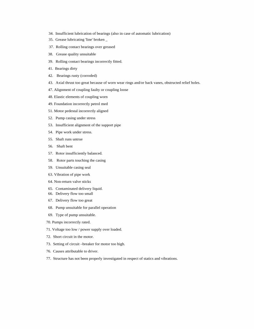
34. Insufficient lubrication of bearings (also in case of automatic lubrication) 35. Grease lubricating 'line' broken _
37. Rolling contact bearings over greased
38. Grease quality unsuitable 39. Rolling contact bearings incorrectly fitted.
41. Bearings dirty
42. Bearings rusty (corroded)
43. Axial thrust too great because of worn wear rings and/or back vanes, obstructed relief holes.
47. Alignment of coupling faulty or coupling loose
48. Elastic elements of coupling worn
49. Foundation incorrectly petrol med
51. Motor pedestal incorrectly aligned
52. Pump casing under stress
53. Insufficient alignment of the support pipe
54. Pipe work under stress.
55. Shaft runs untrue
56. Shaft bent
57. Rotor insufficiently balanced.
58. Rotor parts touching the casing
59. Unsuitable casing seal
63. Vibration of pipe work
64. Non-return valve sticks
65. Contaminated delivery liquid. 66. Delivery flow too small
67. Delivery flow too great
68. Pump unsuitable for parallel operation
69. Type of pump unsuitable.
70. Pumps incorrectly rated.
71. Voltage too low / power supply over loaded.
72. Short circuit in the motor.
73. Setting of circuit –breaker for motor too high.
76. Causes attributable to driver.
77. Structure has not been properly investigated in respect of statics and vibrations.
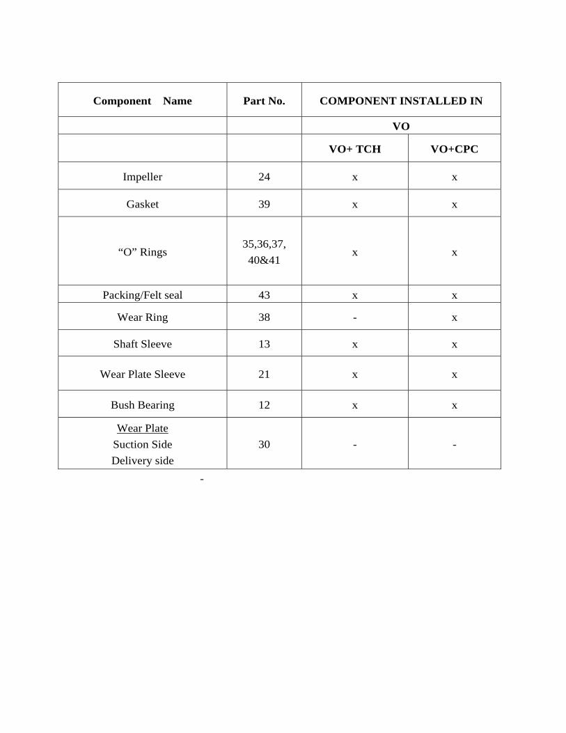
Component Name Part No. COMPONENT INSTALLED IN
VO
VO+ TCH VO+CPC
Impeller 24 x x
Gasket 39 x x
“O” Rings 35,36,37, 40&41
x x
Packing/Felt seal 43 x x
Wear Ring 38 - x
Shaft Sleeve 13 x x
Wear Plate Sleeve 21 x x
Bush Bearing 12 x x
Wear Plate Suction Side Delivery side
30 - -
-