Embed Size (px)
Citation preview
A P P L I C A T I O N S G U I D E
Voice Evacuation Systems

1
A P P L I C A T I O N S G U I D E
Voice Evacuation Systems
ContentsSection 1: Introduction . . . . . . . . . . . . . . . . . . . . . . . . . . . . . . . . . . . . . . . . . . . . . . . . . . . . . . . . . . . . . . . . . . . . . . . . . . . . . . . . . . . . . . . . . . . . . . . . . . . . . . . . . . . . . . . . . . . . . . . . . . . 2Section 2: Basics of sound . . . . . . . . . . . . . . . . . . . . . . . . . . . . . . . . . . . . . . . . . . . . . . . . . . . . . . . . . . . . . . . . . . . . . . . . . . . . . . . . . . . . . . . . . . . . . . . . . . . . . . . . . . . . . . . . . . . . . . . . 2 What is sound? . . . . . . . . . . . . . . . . . . . . . . . . . . . . . . . . . . . . . . . . . . . . . . . . . . . . . . . . . . . . . . . . . . . . . . . . . . . . . . . . . . . . . . . . . . . . . . . . . . . . . . . . . . . . . . . . . . . . . . . . . . . . . . 2 How is sound created? . . . . . . . . . . . . . . . . . . . . . . . . . . . . . . . . . . . . . . . . . . . . . . . . . . . . . . . . . . . . . . . . . . . . . . . . . . . . . . . . . . . . . . . . . . . . . . . . . . . . . . . . . . . . . . . . . . . . . . . . 2 How does sound travel? . . . . . . . . . . . . . . . . . . . . . . . . . . . . . . . . . . . . . . . . . . . . . . . . . . . . . . . . . . . . . . . . . . . . . . . . . . . . . . . . . . . . . . . . . . . . . . . . . . . . . . . . . . . . . . . . . . . . . . . 2Section 3: Measuring sound output . . . . . . . . . . . . . . . . . . . . . . . . . . . . . . . . . . . . . . . . . . . . . . . . . . . . . . . . . . . . . . . . . . . . . . . . . . . . . . . . . . . . . . . . . . . . . . . . . . . . . . . . . . . . . . . . 2 Sound pressure level (SPL) . . . . . . . . . . . . . . . . . . . . . . . . . . . . . . . . . . . . . . . . . . . . . . . . . . . . . . . . . . . . . . . . . . . . . . . . . . . . . . . . . . . . . . . . . . . . . . . . . . . . . . . . . . . . . . . . . . . . 2 Decibels (dB) . . . . . . . . . . . . . . . . . . . . . . . . . . . . . . . . . . . . . . . . . . . . . . . . . . . . . . . . . . . . . . . . . . . . . . . . . . . . . . . . . . . . . . . . . . . . . . . . . . . . . . . . . . . . . . . . . . . . . . . . . . . . . . . . 3 A-weighted scale . . . . . . . . . . . . . . . . . . . . . . . . . . . . . . . . . . . . . . . . . . . . . . . . . . . . . . . . . . . . . . . . . . . . . . . . . . . . . . . . . . . . . . . . . . . . . . . . . . . . . . . . . . . . . . . . . . . . . . . . . . . . . 3 Adding SPL from two speakers . . . . . . . . . . . . . . . . . . . . . . . . . . . . . . . . . . . . . . . . . . . . . . . . . . . . . . . . . . . . . . . . . . . . . . . . . . . . . . . . . . . . . . . . . . . . . . . . . . . . . . . . . . . . . . . . . 3 Rules of thumb pertaining to dB . . . . . . . . . . . . . . . . . . . . . . . . . . . . . . . . . . . . . . . . . . . . . . . . . . . . . . . . . . . . . . . . . . . . . . . . . . . . . . . . . . . . . . . . . . . . . . . . . . . . . . . . . . . . . . . . 3Section 4: Basics of speaker operation . . . . . . . . . . . . . . . . . . . . . . . . . . . . . . . . . . . . . . . . . . . . . . . . . . . . . . . . . . . . . . . . . . . . . . . . . . . . . . . . . . . . . . . . . . . . . . . . . . . . . . . . . . . . . 3 Parts of a speaker . . . . . . . . . . . . . . . . . . . . . . . . . . . . . . . . . . . . . . . . . . . . . . . . . . . . . . . . . . . . . . . . . . . . . . . . . . . . . . . . . . . . . . . . . . . . . . . . . . . . . . . . . . . . . . . . . . . . . . . . . . . . 3 Theory of operation . . . . . . . . . . . . . . . . . . . . . . . . . . . . . . . . . . . . . . . . . . . . . . . . . . . . . . . . . . . . . . . . . . . . . . . . . . . . . . . . . . . . . . . . . . . . . . . . . . . . . . . . . . . . . . . . . . . . . . . . . . . 3 Cone materials . . . . . . . . . . . . . . . . . . . . . . . . . . . . . . . . . . . . . . . . . . . . . . . . . . . . . . . . . . . . . . . . . . . . . . . . . . . . . . . . . . . . . . . . . . . . . . . . . . . . . . . . . . . . . . . . . . . . . . . . . . . . . . . 4 Speakers for particular frequency bands . . . . . . . . . . . . . . . . . . . . . . . . . . . . . . . . . . . . . . . . . . . . . . . . . . . . . . . . . . . . . . . . . . . . . . . . . . . . . . . . . . . . . . . . . . . . . . . . . . . . . . . . 4 Types of speakers . . . . . . . . . . . . . . . . . . . . . . . . . . . . . . . . . . . . . . . . . . . . . . . . . . . . . . . . . . . . . . . . . . . . . . . . . . . . . . . . . . . . . . . . . . . . . . . . . . . . . . . . . . . . . . . . . . . . . . . . . . . . 4 Full Range Versus Component Systems . . . . . . . . . . . . . . . . . . . . . . . . . . . . . . . . . . . . . . . . . . . . . . . . . . . . . . . . . . . . . . . . . . . . . . . . . . . . . . . . . . . . . . . . . . . . . . . . . . . . . . . 4 High Impedance (70 .7 volt/25 volt) Distributed Line Systems . . . . . . . . . . . . . . . . . . . . . . . . . . . . . . . . . . . . . . . . . . . . . . . . . . . . . . . . . . . . . . . . . . . . . . . . . . . . . . . . . . . . . . . 5Section 5: Basics of voice evacuation system amplifiers . . . . . . . . . . . . . . . . . . . . . . . . . . . . . . . . . . . . . . . . . . . . . . . . . . . . . . . . . . . . . . . . . . . . . . . . . . . . . . . . . . . . . . . . . . . . . . 5Section 6: Standards that relate to speakers . . . . . . . . . . . . . . . . . . . . . . . . . . . . . . . . . . . . . . . . . . . . . . . . . . . . . . . . . . . . . . . . . . . . . . . . . . . . . . . . . . . . . . . . . . . . . . . . . . . . . . . . 5 Americans with Disabilities Act Accessibility Guidelines . . . . . . . . . . . . . . . . . . . . . . . . . . . . . . . . . . . . . . . . . . . . . . . . . . . . . . . . . . . . . . . . . . . . . . . . . . . . . . . . . . . . . . . . . . 5 UL 1480 . . . . . . . . . . . . . . . . . . . . . . . . . . . . . . . . . . . . . . . . . . . . . . . . . . . . . . . . . . . . . . . . . . . . . . . . . . . . . . . . . . . . . . . . . . . . . . . . . . . . . . . . . . . . . . . . . . . . . . . . . . . . . . . . . . . . . . 6 Audibility tests . . . . . . . . . . . . . . . . . . . . . . . . . . . . . . . . . . . . . . . . . . . . . . . . . . . . . . . . . . . . . . . . . . . . . . . . . . . . . . . . . . . . . . . . . . . . . . . . . . . . . . . . . . . . . . . . . . . . . . . . . . . . . 6 Frequency response requirements . . . . . . . . . . . . . . . . . . . . . . . . . . . . . . . . . . . . . . . . . . . . . . . . . . . . . . . . . . . . . . . . . . . . . . . . . . . . . . . . . . . . . . . . . . . . . . . . . . . . . . . . . . . 6 ULC-S541-99 . . . . . . . . . . . . . . . . . . . . . . . . . . . . . . . . . . . . . . . . . . . . . . . . . . . . . . . . . . . . . . . . . . . . . . . . . . . . . . . . . . . . . . . . . . . . . . . . . . . . . . . . . . . . . . . . . . . . . . . . . . . . . . . . . 6 Frequency response and output sound pressure level requirements . . . . . . . . . . . . . . . . . . . . . . . . . . . . . . . . . . . . . . . . . . . . . . . . . . . . . . . . . . . . . . . . . . . . . . . . . . . . . 6 Harmonic distortion . . . . . . . . . . . . . . . . . . . . . . . . . . . . . . . . . . . . . . . . . . . . . . . . . . . . . . . . . . . . . . . . . . . . . . . . . . . . . . . . . . . . . . . . . . . . . . . . . . . . . . . . . . . . . . . . . . . . . . . . 6 Anechoic vs . Reverberant chamber testing . . . . . . . . . . . . . . . . . . . . . . . . . . . . . . . . . . . . . . . . . . . . . . . . . . . . . . . . . . . . . . . . . . . . . . . . . . . . . . . . . . . . . . . . . . . . . . . . . . . . . . 6Section 7: Codes that relate to voice evacuation design . . . . . . . . . . . . . . . . . . . . . . . . . . . . . . . . . . . . . . . . . . . . . . . . . . . . . . . . . . . . . . . . . . . . . . . . . . . . . . . . . . . . . . . . . . . . . 7 NFPA 72; Chapter 7 requirements . . . . . . . . . . . . . . . . . . . . . . . . . . . . . . . . . . . . . . . . . . . . . . . . . . . . . . . . . . . . . . . . . . . . . . . . . . . . . . . . . . . . . . . . . . . . . . . . . . . . . . . . . . . . . . . 7 Audibility requirements . . . . . . . . . . . . . . . . . . . . . . . . . . . . . . . . . . . . . . . . . . . . . . . . . . . . . . . . . . . . . . . . . . . . . . . . . . . . . . . . . . . . . . . . . . . . . . . . . . . . . . . . . . . . . . . . . . . . . 7 Intelligibility requirements . . . . . . . . . . . . . . . . . . . . . . . . . . . . . . . . . . . . . . . . . . . . . . . . . . . . . . . . . . . . . . . . . . . . . . . . . . . . . . . . . . . . . . . . . . . . . . . . . . . . . . . . . . . . . . . . . . 7 Narrow band signaling . . . . . . . . . . . . . . . . . . . . . . . . . . . . . . . . . . . . . . . . . . . . . . . . . . . . . . . . . . . . . . . . . . . . . . . . . . . . . . . . . . . . . . . . . . . . . . . . . . . . . . . . . . . . . . . . . . . . . 7 NFPA 101 . . . . . . . . . . . . . . . . . . . . . . . . . . . . . . . . . . . . . . . . . . . . . . . . . . . . . . . . . . . . . . . . . . . . . . . . . . . . . . . . . . . . . . . . . . . . . . . . . . . . . . . . . . . . . . . . . . . . . . . . . . . . . . . . . . . . 7 NFPA 1 . . . . . . . . . . . . . . . . . . . . . . . . . . . . . . . . . . . . . . . . . . . . . . . . . . . . . . . . . . . . . . . . . . . . . . . . . . . . . . . . . . . . . . . . . . . . . . . . . . . . . . . . . . . . . . . . . . . . . . . . . . . . . . . . . . . . . . 8 International Building Code & International Fire Code . . . . . . . . . . . . . . . . . . . . . . . . . . . . . . . . . . . . . . . . . . . . . . . . . . . . . . . . . . . . . . . . . . . . . . . . . . . . . . . . . . . . . . . . . . . . . 8Section 8: System Design . . . . . . . . . . . . . . . . . . . . . . . . . . . . . . . . . . . . . . . . . . . . . . . . . . . . . . . . . . . . . . . . . . . . . . . . . . . . . . . . . . . . . . . . . . . . . . . . . . . . . . . . . . . . . . . . . . . . . . . . . 8 Speaker frequency response . . . . . . . . . . . . . . . . . . . . . . . . . . . . . . . . . . . . . . . . . . . . . . . . . . . . . . . . . . . . . . . . . . . . . . . . . . . . . . . . . . . . . . . . . . . . . . . . . . . . . . . . . . . . . . . . . . 8 Total harmonic distortion . . . . . . . . . . . . . . . . . . . . . . . . . . . . . . . . . . . . . . . . . . . . . . . . . . . . . . . . . . . . . . . . . . . . . . . . . . . . . . . . . . . . . . . . . . . . . . . . . . . . . . . . . . . . . . . . . . . . . . 8 How to lay out speakers to meet NFPA requirements . . . . . . . . . . . . . . . . . . . . . . . . . . . . . . . . . . . . . . . . . . . . . . . . . . . . . . . . . . . . . . . . . . . . . . . . . . . . . . . . . . . . . . . . . . . . . 8 Voltage drop on speaker circuits . . . . . . . . . . . . . . . . . . . . . . . . . . . . . . . . . . . . . . . . . . . . . . . . . . . . . . . . . . . . . . . . . . . . . . . . . . . . . . . . . . . . . . . . . . . . . . . . . . . . . . . . . . . . . . . 9Section 9: Intelligibility . . . . . . . . . . . . . . . . . . . . . . . . . . . . . . . . . . . . . . . . . . . . . . . . . . . . . . . . . . . . . . . . . . . . . . . . . . . . . . . . . . . . . . . . . . . . . . . . . . . . . . . . . . . . . . . . . . . . . . . . . . 10 Definition . . . . . . . . . . . . . . . . . . . . . . . . . . . . . . . . . . . . . . . . . . . . . . . . . . . . . . . . . . . . . . . . . . . . . . . . . . . . . . . . . . . . . . . . . . . . . . . . . . . . . . . . . . . . . . . . . . . . . . . . . . . . . . . . . . . 10 Factors that are controllable by a voice evacuation system designer . . . . . . . . . . . . . . . . . . . . . . . . . . . . . . . . . . . . . . . . . . . . . . . . . . . . . . . . . . . . . . . . . . . . . . . . . . . . . . 10 Factors that aren’t controllable by a system designer . . . . . . . . . . . . . . . . . . . . . . . . . . . . . . . . . . . . . . . . . . . . . . . . . . . . . . . . . . . . . . . . . . . . . . . . . . . . . . . . . . . . . . . . . . . . 10 Measurement methods . . . . . . . . . . . . . . . . . . . . . . . . . . . . . . . . . . . . . . . . . . . . . . . . . . . . . . . . . . . . . . . . . . . . . . . . . . . . . . . . . . . . . . . . . . . . . . . . . . . . . . . . . . . . . . . . . . . . . . . 10References . . . . . . . . . . . . . . . . . . . . . . . . . . . . . . . . . . . . . . . . . . . . . . . . . . . . . . . . . . . . . . . . . . . . . . . . . . . . . . . . . . . . . . . . . . . . . . . . . . . . . . . . . . . . . . . . . . . . . . . . . . . . . . . . . . . . 12Glossary . . . . . . . . . . . . . . . . . . . . . . . . . . . . . . . . . . . . . . . . . . . . . . . . . . . . . . . . . . . . . . . . . . . . . . . . . . . . . . . . . . . . . . . . . . . . . . . . . . . . . . . . . . . . . . . . . . . . . . . . . . . . . . . . . . . . . . . 12
V O I C E E V A C U A T I O N S Y S T E M
Section 1
Introduction
The purpose of this guide is to provide information about voice evacuation systems used in conjunction with fire alarm systems. It outlines basic principles that should be considered in the design of systems. Though this information is based upon industry expertise and many years of experience, it is intend-ed to be used only as a guide. The requirements of applicable codes and standards, as well as directives of the Authorities Having Jurisdiction (AHJ) should be followed. In particular, the most current version of NFPA 72 for installation and testing of systems is a key element in the effectiveness of voice evacua-tion systems.
Section 2
Basics of Sound
What Is sound?Sound is the result of changing air pressure over time.
hoW Is sound Created?More technically speaking, air contains molecules, or small particles, that are continuously in motion. Each molecule exerts small pressure deviations on the steady-state atmospheric pressure. When an object, such as a speaker, is set into vibration, the molecules travel parallel to the direction in which the wave spreads.
hoW does sound travel?However, the air molecules themselves don’t move very far. They simply transfer these pressure chang-es into sound waves. Sound waves move away from the sound source, such as a speaker, at a speed determined by the sound source. The further the distance from the sound source, the less intense the sound waves become.
Imagine a swimming pool full of children. One child takes a flying leap off the edge and drops like a cannonball into the water. As the seconds pass, you see the ring of waves spread from the child out to the edges of the pool. Sound waves work in the same way. The more power the source, or speaker, emits, the wider the sound waves spread. The fur-ther out the sound waves travel, the less intense they become.
Regularly, though, the sound waves are intercepted by other sound waves. Imagine two children jump-ing into the water at the same time. Their waves overlap. Similarly, when a sound wave is intercepted by an outside force, a portion is reflected into a different direction. If you are installing fire system speakers in a high-ambient noise environment,
understanding sound output is imperative to repro-ducing an audible message.
Section 3
Measuring Sound Output
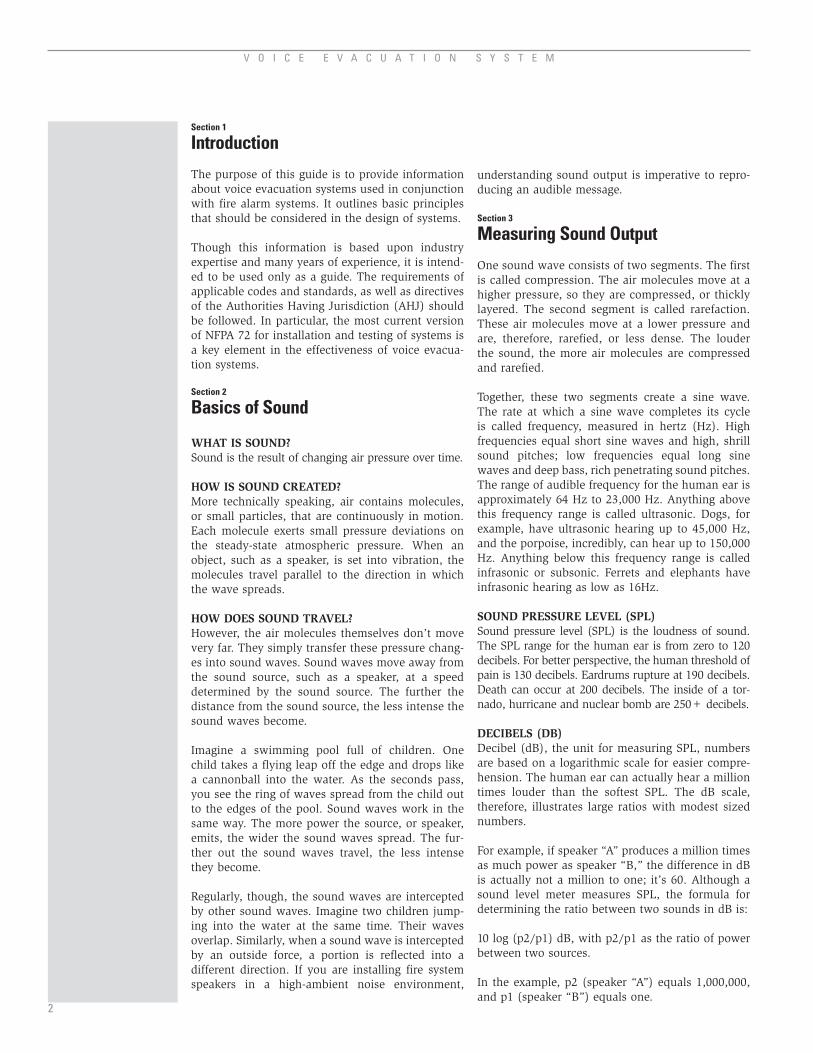
One sound wave consists of two segments. The first is called compression. The air molecules move at a higher pressure, so they are compressed, or thickly layered. The second segment is called rarefaction. These air molecules move at a lower pressure and are, therefore, rarefied, or less dense. The louder the sound, the more air molecules are compressed and rarefied.
Together, these two segments create a sine wave. The rate at which a sine wave completes its cycle is called frequency, measured in hertz (Hz). High frequencies equal short sine waves and high, shrill sound pitches; low frequencies equal long sine waves and deep bass, rich penetrating sound pitches. The range of audible frequency for the human ear is approximately 64 Hz to 23,000 Hz. Anything above this frequency range is called ultrasonic. Dogs, for example, have ultrasonic hearing up to 45,000 Hz, and the porpoise, incredibly, can hear up to 150,000 Hz. Anything below this frequency range is called infrasonic or subsonic. Ferrets and elephants have infrasonic hearing as low as 16Hz.
sound pressure level (spl)Sound pressure level (SPL) is the loudness of sound. The SPL range for the human ear is from zero to 120 decibels. For better perspective, the human threshold of pain is 130 decibels. Eardrums rupture at 190 decibels. Death can occur at 200 decibels. The inside of a tor-nado, hurricane and nuclear bomb are 250+ decibels.
deCIbels (db)Decibel (dB), the unit for measuring SPL, numbers are based on a logarithmic scale for easier compre-hension. The human ear can actually hear a million times louder than the softest SPL. The dB scale, therefore, illustrates large ratios with modest sized numbers.
For example, if speaker “A” produces a million times as much power as speaker “B,” the difference in dB is actually not a million to one; it’s 60. Although a sound level meter measures SPL, the formula for determining the ratio between two sounds in dB is: 10 log (p2/p1) dB, with p2/p1 as the ratio of power between two sources.
In the example, p2 (speaker “A”) equals 1,000,000, and p1 (speaker “B”) equals one.
2
S Y S T E M S E N S O RS Y S T E M S E N S O R
Therefore:10 log (p2/p1) dB = 10 log (1,000,000/1) dB = 10 log (1,000,000) dB = 60 dB
+60 dB
Whisper Busy Street
a-WeIghted sCaleAn A-weighting filter is sometimes used when mea-suring SPL with frequencies around 3,000-6,000Hz. Because the human ear is most sensitive in this range, the filter ensures that the measured dB cor-responds with perceived loudness. In other words, the filter desensitizes the sound level meter to the extreme high and low frequencies. These sound lev-els are still measured in decibels, but are symbolized by dBA. Other weighting scales are sometimes used in other applications.
addIng spl from tWo speakersIf you have two speakers that are in close proximity, the sound from the speakers is additive. However, you can’t simply add the two dB levels to determine the sound level. For example, one 80 dB speaker plus a second 80 dB speaker does not equal 160 dB.Instead, you have to convert the SPLs back to their actual powers, add them and then, recalculate the level in dB. To simplify this process, a calculator on the System Sensor web site is available (www.systemsensor.com).
If the two dB level are identical, then you simply add 3 dB to either one. If the SPL from one speaker is more than 10 dB higher than the other, then you can simply use the higher SPL dB value.
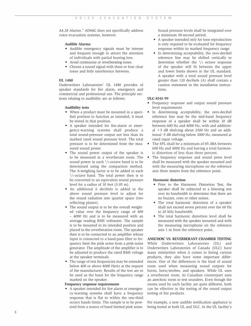
rules of thumb pertaInIng to dbSound pressure levels drop by 6 dB for every dou-bling of distance and increase by 3 dB for every dou-bling of power. For example, take a one watt speaker that provides 85 dBA at 10 feet. At two watts, the speaker will provide 82 dBA at 20 feet and 88 dBA at 10 feet. This rule of thumb is important to remember when determining whether you need fewer high-powered centralized speakers or more low-powered, dispersed speakers.
10ft
84 dBA
1W
10ft
87 dBA
2W
20ft
81 dBA
2W
Figure 2 . Rules of Thumb Pertaining to dB .
Section 4
Basics of Speaker Operation
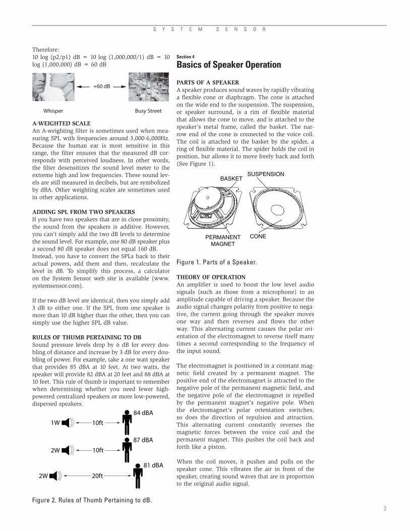
parts of a speakerA speaker produces sound waves by rapidly vibrating a flexible cone or diaphragm. The cone is attached on the wide end to the suspension. The suspension, or speaker surround, is a rim of flexible material that allows the cone to move, and is attached to the speaker’s metal frame, called the basket. The nar-row end of the cone is connected to the voice coil. The coil is attached to the basket by the spider, a ring of flexible material. The spider holds the coil in position, but allows it to move freely back and forth (See Figure 1).
BASKET
PERMANENTMAGNET
SUSPENSION
CONE
Figure 1 . Parts of a Speaker .
theory of operatIon An amplifier is used to boost the low level audio signals (such as those from a microphone) to an amplitude capable of driving a speaker. Because the audio signal changes polarity from positive to nega-tive, the current going through the speaker moves one way and then reverses and flows the other way. This alternating current causes the polar ori-entation of the electromagnet to reverse itself many times a second corresponding to the frequency of the input sound.
The electromagnet is positioned in a constant mag-netic field created by a permanent magnet. The positive end of the electromagnet is attracted to the negative pole of the permanent magnetic field, and the negative pole of the electromagnet is repelled by the permanent magnet’s negative pole. When the electromagnet’s polar orientation switches, so does the direction of repulsion and attraction. This alternating current constantly reverses the magnetic forces between the voice coil and the permanent magnet. This pushes the coil back and forth like a piston.
When the coil moves, it pushes and pulls on the speaker cone. This vibrates the air in front of the speaker, creating sound waves that are in proportion to the original audio signal.
3

V O I C E E V A C U A T I O N S Y S T E M
Cone materIalsThe cone, the part of the speaker that physically moves the air molecules, comes in a variety of materials, including paper, polypropylene and car-bon fiber.
Paper is the conventional material for speaker cones. Among its simplicities is its flexibility to form into a wide variety of shapes. However, the paper must be chemically coated to adjust to changes in the environment, such as humidity. As humidity increases, the percentage of moisture within the paper increases. This leads to changes in cone mass and other parameters. Despite this and its simplistic technology, a well engineered paper cone can still deliver frequency responses as smooth as any high technology material.
Polypropylene is a thermoplastic polymer. In other words, polypropylene is a plastic material that melts to a liquid when heated over 320 degrees Fahrenheit and freezes to a brittle, glassy state when cooled. Polypropylene is found in objects such as dishwash-er-safe food containers and outdoor winter apparel. It’s also the most common plastic material used in speaker cones because of its immunity to humidity fluctuations, its high-frequency response and its con-sistent performance. On the other hand, some people feel that this material can slowly stretch under stress, or that generated heat can soften the cone.
Carbon fiber is composite material made from a fabric of fibers that are bonded by an epoxy resin, a tar-like material found in strong glues and enamels. These fibers have a high degree of tensile potency. As a result, the stiffness and damping characteristics of carbon fiber provide a lower degree of vibration to speaker cones, resulting in a crisp reproduction of sound.
speakers for partICularfrequenCy bandsWoofers, tweeters, and mid-range speakers are loud-speakers, also known as drivers. They are designed to reproduce sound at different frequencies.
Woofers, for example, are designed to produce the lowest frequencies (20Hz to 200Hz). Their cones are suspended to maximize a back and forth exten-sion because, as we learned, sine waves lengthen as they become lower in frequency (see Measuring Sound Output).
Mid-range speakers, on the other hand, have less cone extension. Tweeters are almost motionless, producing the highest frequencies; reminiscent of violins, flutes and birds. Even so, mid-range speak-ers and tweeters can produce sound within their frequency range just as powerfully as woofers.
Now, if you placed a woofer on top of your kitchen table, it would eventually vibrate itself right onto
your floor. So, in order to absorb the vibrations, woofers must be surrounded by heavy wood, or other solid material, called enclosures. Although enclosures exist solely to accommodate woofers, mid ranges and tweeters are often mounted within the enclosures for convenience.
In order to understand how the enclosures affect sound quality, make note that drivers are exposed to air in front and back, hence emitting sound forward and backward. The backward-radiated sound, called a backwave, can cause interference with or cancel out front waves.
There are two main types of speaker enclosures, and they deal with backwaves differently. Sealed speaker enclosures simply seal off the speaker’s backwave, reproducing a fairly broad frequency range with little deviation or distortion.
Bass reflex enclosures, on the other hand, make use of the back wave. By installing a tube in the enclo-sure, the back wave is routed through the tube. If the tube is long enough, the back wave, at certain frequencies, will be more in sync with and reinforce the front wave. The enclosure, therefore, assists the driver at the point where its output is weakening, thus, extending the low frequency response.
types of speakers full range versus Component systems Speakers can be divided into two categories: full
range and component. Full range speakers, also known as coaxial speakers, mount a woofer for the low frequencies, a tweeter to produce the high frequencies and sometimes a mid-range inside the woofer cone. Full-range speakers are ideal for quick and simple replacement applications.
Component speakers include collaborating parts (called components): a woofer, a tweeter and a crossover (a network of filters, coils and capaci-tors that direct specific frequency ranges to the appropriate speaker components). The com-ponents are made of better materials than full-range speaker parts and are not connected by the woofer cone. The tweeters can be mounted in a place that provides the most realistic sound.
hIgh ImpedanCe (70.7 volt/25 volt) dIstrIbuted lIne systems:
Impedance, expressed in ohms, is the resistance within the enclosure to a flow of power from a speaker’s amplifier, or receiver. To better under-stand impedance, imagine a water pipe and pump. The water pump acts as your amplifier, pumping volts (pressure measured in volts) and current (flow measured in amperes) through the water pipe. The water flowing through the pipe, a combination of the volts and current, is your power (measured in watts). The diameter of the pipe itself is the impedance.
4

S Y S T E M S E N S O RS Y S T E M S E N S O R
If your water pipe is too large (low impedance, or little resistance), the pump must supply more current in order to fill the pipe with water. Because this puts strain on the pump, you will need a higher-powered pump. On the flip side, if your water pipe is too small (high impedance, or high resistance), the current will be restricted, disrupting the water flow.
In order to make large sound systems cost effective and easy to design, constant-voltage systems were developed. Direct drive, low volt-age speaker systems (like a home stereo system) would simply not be practical over long wire distances because of voltage drop. So, a system was developed that produced constant voltage at all of the speakers in the system. Constant-voltage fire alarm speaker systems in the United States require 70.7 volt or 25 volt distributed line systems, also known as 70 volt and 25 volt systems. These systems not only provide a safe, efficient way to connect many loudspeakers to one amplifier and make impedance-matching simpler, they ensure optimum volume; eliminate wasted power, stress or damage to the ampli-fier and speakers; and reduce reverberant noise, distortion and uneven sound distribution. See Figure 3 and 4.
8ΩTOAMPLIFIER
8Ω SPEAKER
Figure 3 . A Typical Low Impedance System (direct drive) .
8Ω
TO AMPLIFIER OUTPUT
STEP-UP TRANSFORMER
STEP-DOWN TRANSFORMER
SPEAKER CABLE
SPEAKERLOWIMPEDANCE
25 OR 70 VOLTS
HIGHIMPEDANCE
Figure 4 . A Typical High Impedance System .
The idea of constant-voltage speaker systems
comes from electrical power distribution. The power company boosts the voltage of the elec-tricity at the source to very high voltages to get it from point A to point B and then steps it back down for the homeowner. The power company does this to minimize the loss of power on the distribution wires. The same principle works for audio signals. It should be noted that the transfer of power form 8 ohm to 25 (or 70 volt) audio systems causes a loss of power due to losses in
the transformers at the power source and at the speaker.
Although the principles of operation for 70 volt and 25 volt systems are the same, the 25 volt system is a less efficient way to achieve similar results. Most constant-voltage distributed sound systems in the U.S. use a 70 volt signal, which allows longer wire runs. It should be noted that 70 volt systems can have 8 times longer circuit runs for the same wire gauge. See “Voltage Drop on Speaker Circuits” section for more information.
Twenty-five volt systems, on the other hand, don’t
require conduit, or tubes for electrical wires, and are exempt from many local safety codes. Because of this additional safety, almost all educational facilities require the 25 volt standard.
Most fire alarm speakers support both voltages, so whether you choose to install the 70 volt or 25 volt system, make sure your speakers have dual-voltage transformers with primary power taps. This will allow you to stock and use one product for both applications.
Section 5
Basics of voice evacuation system amplifiers
Voice evacuation system amplifiers, also known as voice evacuation panels, are a key component of fire alarm systems as they play back recorded program-mable messages for emergency communications. To ensure they are operational, standard amplifier features include indicator messages for power, sys-tem trouble, message generator trouble, microphone trouble, record/playback, status of speaker zones, battery trouble, speaker circuit trouble and others.
Other standard amplifier features are field adjustable voltage (25 or 70.7 volts), built-in alert tone genera-tors with steady, slow whoop, high/low or chime capabilities, field selectable tones, speaker zone control, independently field-programmable input circuits, power limited outputs, auxiliary power outputs that provide local power for addressable control modules and compatibility with fire alarm control panels.
Section 6
Standards that relate to speakers
amerICans WIth dIsabIlItIes aCt aCCessIbIlIty guIdelInesThe Americans with Disabilities Act Accessibility Guidelines (ADAAG) lists the technical requirements for accessibility to buildings and facilities by individ-uals with disabilities. The principle standards relating to alarms can be found in “4. Accessible Elements and Spaces: Scope and Technical Requirements.
5
V O I C E E V A C U A T I O N S Y S T E M
16
A4.28 Alarms.” AD44G does not specifically address voice evacuation systems, however.
audible alarms: Audible emergency signals must be intense and frequent enough to attract the attention of individuals with partial hearing loss. Avoid continuous or reverberating tones. Choose a sound signal with three or four clear tones and little interference between.
ul 1480Underwriters Laboratories’ UL 1480 provides of speaker standards for fire alarm, emergency and commercial and professional use. The principle sec-tions relating to audibility are as follows:
audibility tests When a product must be mounted in a speci-fied position to function as intended, it must be tested in that position. A speaker intended for fire-alarm or emer-gency-warning systems shall produce a total sound-pressure output not less than its marked rated sound pressure level. The total pressure is to be determined from the mea-sured sound power. The sound power output of the speaker is to be measured in a reverberant room. The sound power in each 1/3-octave band is to be determined using the comparison method. The A-weighing factor is to be added to each 1/3-octave band. The total power then is to be converted to an equivalent sound pressure level for a radius of 10 feet (3.05 m). An additional 6 decibels is added to the above sound pressure level to adjust for the sound radiation into quarter space (two reflecting planes). The sound output is to be the overall weight-ed value over the frequency range of 400 – 4000 Hz and is to be measured with an average reading RMS voltmeter. The sample is to be mounted in its intended position and placed in the reverberation room. The speaker then is to be connected to an amplifier whose input is connected to a band-pass filter to fre-quency limit the pink noise from a pink-noise generator. The amplitude of the amplifier is to be adjusted to produce the rated RMS voltage at the speaker terminals. The range of test frequencies may be extended below 400 or above 4000 Hertz at the request of the manufacturer. Results of the test are to be used as the basis for the frequency range marked on the speaker.
frequency response requirements A speaker intended for fire-alarm or emergen-cy-warning systems shall have a frequency response that is flat to within the one-third octave bands limits. The sample is to be pow-ered from a source of band limited pink noise.
•
••
•
•
•
•
•
•
•
Sound pressure levels shall be integrated over a minimum 30-second period. A speaker intended only for tone reproduction is only required to be evaluated for frequency response within its marked frequency range. In determining acceptability, the zero-decibel reference line may be shifted vertically to determine whether the 1/3 octave response of the speaker will fit between the upper and lower limits shown in the UL standard. A speaker with a total sound pressure level greater than 120 decibels (A) shall contain a caution statement in the installation instruc-tions.
ulC-s541-99 Frequency response and output sound pressure level requirements In determining acceptability, the zero-decibel reference line may be the mid-band frequency response of a speaker shall be within 10 dB between 600 Hz and 4000 Hz, with and addition-al +5 dB shelving about 2500 Hz and an addi-tional -5 dB shelving below 1000 Hz, measured at rated input voltage. The SPL shall be a minimum of 85 dBA between 600 Hz and 4000 Hz and having a total harmon-ic distortion of less than three percent. The frequency response and sound press level shall be measured with the speaker mounted and with the measuring microphone on the reference axis three meters from the reference point.
harmonic distortion Prior to the Harmonic Distortion Test, the speaker shall be subjected to a listening test over its bandwidth to determine that there are no buzzes, cries or other noises. The total harmonic distortion of a speaker shall not exceed seven percent over the 60 Hz to 20 kHz bandwidth. The total harmonic distortion level shall be measured with the speaker mounted and with the measuring microphone on the reference axis 1 m from the reference point.
aneChoIC vs. reverberant Chamber testIng While Underwriters Laboratories (UL) and Underwriters Laboratories of Canada (ULC) have many similarities when it comes to listing various products, they also have some important differ-ences. One of the differences is the kind of sound room used when measuring sound outputs for horns, horn/strobes, and speakers. While UL uses a reverberant room, its Canadian counterpart uses an anechoic room to test sounders. Even though the rooms used by each facility are quite different, both can be effective in the testing of the sound output testing of fire products.
For example, a new audible notification appliance is being tested at both UL and ULC. In the UL facility’s
•
•
•
•
•
•
•
•
•

S Y S T E M S E N S O RS Y S T E M S E N S O R
7
reverberant chamber, the horn’s sound pressure level measures 75 decibels at 24 volts DC. In the ULC facility’s anechoic chamber, the same horn might sound at 96 decibels at 24 volts DC. While the results are different at each facility, both are consid-ered acceptable in their respective area.
The UL’s reverberation chamber is often used to measure the sound absorption of products such as theater seating, carpets and other noise barriers. When rooms are being designed, it is important that the absorption properties of the surfaces in the room are known so that the noise level during use can be predicted. One example of an area with poor rever-berant conditions is a railway station. Most of these stations are too reverberant (have too little absorp-tion), which can make verbal communication very difficult. Knowing the absorption of building ele-ments is important to avoid such design mistakes.
Section 7
Codes that relate to voiceevacuation design
nfpa 72; Chapter 7 requirementsThis information is from NFPA 72, National Fire Alarm Code, 2007 edition.
The National Fire Protection Association (NFPA) publishes standards for the proper application, installation and maintenance of fire protection products. The principle standards relating to voice evacuation are as follows:
nfpa 72, Chapter 7: notification appliances for fire alarm systemsNFPA 72 guarantees a reasonable degree of pro-tection for life and property from fire by defining requirements for signal initiation, transmission, notification and annunciation, as well as the levels of performance and the reliability of various fire alarm systems.
audibility requirements General:
Average ambient sound levels greater than 105 dBA require visible notification appliances. Total sound pressure levels produced by ambient sound pressure levels and all operat-ing audible notification appliances must not exceed 120 dBA within the occupied area.
Public mode: Audible public mode signals must have a sound level of at least 15 dB above the average ambient sound level or 5 dB above the maximum sound level having a dura-tion of at least 60 seconds, whichever is greater. Measurements must be taken with an A-weighted scale (dBA) at 5 feet above the floor in occupied areas.
•
•
•
Private mode: Audible private mode signals must have a sound level of at least 10 dB above the aver-age ambient sound level or 5 dB above the maximum sound level for at least 60 seconds, whichever is greater. Measurements must be taken with an A-weighted scale (dBA) at 5 feet above the floor in occupied areas. In sleeping areas, audible appliances must have a sound level of at least 15 dB above the average ambient sound level, or 5 dB above the maximum sound level for at least 60 seconds, or a sound level of at least 75 dB, whichever is greater. Measurements must be taken with an A-weighted scale (dBA) at pil-low level in occupied areas.
Intelligibility requirements Where required, emergency voice/alarm commu-
nications systems must be able to reproduce prere-corded or live messages with voice intelligibility.
narrow band signaling Narrow band signaling is now an acceptable
alternative method allowed by NFPA 72 for ensuring the audibility of voice evacuation sys-tems. It is primarily used in applications that have a high ambient noise level, such as facto-ries, where meeting the 15 dB requirement in the code is not practical.
Narrow band signaling is based on the principle
that for a signal to be audible, it need only exceed the background noise in a small frequency band. The 15 dB above ambient requirement in the code is an oversimplification that sometimes results in systems that are over designed (louder than necessary). Essentially, the narrow band signaling method is implemented by first per-forming an analysis of the ambient noise in the area that will be covered by the voice evacuation system. The amplitude of the noise across the audible spectrum needs to be determined. Once that information is known, a system designer can select a frequency for an alarm tone that exceeds the noise only in a particular one or 1/3 octave band.
While this method is sound from an engineering standpoint, it requires much greater knowledge on the part of system designers and as such is not yet widely used. There are few fire alarm systems that support this type of design.
nfpa 101, lIfe safety CodeNFPA 101 guarantees a reasonable degree of pro-tection for life and property from fire by providing requirements for designing, operating and maintain-ing buildings. Requirements are based on building type and occupancy. The code outlines specific occupancies that require voice evacuation systems as opposed to ordinary sounders.
•
•

V O I C E E V A C U A T I O N S Y S T E M
nfpa 1, unIform fIre Code™NFPA 1 provides state, county and local jurisdictions with an effective local fire code. The code is compatible with regulatory adoption procedures, including admin-istration and code enforcement, occupancies, pro-cesses, equipment and hazardous materials provisions. This Code is intended to provide state, county, and local jurisdictions with an effective local fire code.
International building Code & International fire CodeThe International Building Code and International Fire Code were created by the ICC in an effort to get all areas of the US to comply with one set of standards. The purpose of the International Building Code and International Fire Code in terms of fire protection is to protect safety to life and property from fire and other hazards attributed to the built environment and to provide safety to fire fighters and emergency responders during emergency opera-tions. BOCA, ICBO and SBCCI formed the umbrella organization ICC. The purpose of ICC is to produce a single set of model building and fire codes. Notably, NFPA is not a member of this organization.
The organizations are:
Building Officials and Code Administrators (BOCA)
• International Conference of Building Officials (ICBO)
• Southern Building Code Congress International (SBCCI)
Section 8
System Design
speaker frequenCy responseRemember that the frequency range of the human ear is approximately 64 Hz to 23,000 Hz (see Measuring Sound Output). A speaker’s frequency response indi-cates how much of that range a speaker can reproduce. The closer the speaker can match the original recording, the more intelligible and natural the output will sound.
Ideally, voice evacuation speakers should have a frequency response between 150 Hz and 11,000 Hz, the frequencies that male and female voices fall into. The frequency response should be as flat as possible, that is, the response should not vary considerably at the low and high ends, in order to reproduce the most intelligible sound. Remember that the frequency response range required by UL for fire alarm systems is 400 - 4Khz.
total harmonIC dIstortIonTotal harmonic distortion (THD) is a key factor in intelligibility. Audio signals suffer some distortion as they pass through electronic circuits. This dis-tortion can be introduced by various components in the voice evacuation system, and the effect is cumulative. Systems designed with low harmonic distortion tend to provide voice messages that are
•
more intelligible than those that do not. Harmonic distortion specifications are typically provided by the manufacturer of the amplifier and speakers on their data sheets.
Mathematically, RMS is a measurement of the magni-tude of a set of numbers. In other words, if you have a set of numbers and want to find the RMS, you first square all the numbers to get rid of any negatives. Then, you take the average of the squares. Finally, you take the square root of the average. In reality, the RMS value of a signal that changes with time is the value that will produce the equivalent amount of heating on a resistive load. That is, it is a way of expressing an AC signal as a single value.
hoW to lay out speakers to meet nfpa requIrementsIn order to lay out speakers for a voice evacuation system, there are several things one needs to know about the speakers and the environment that they will be placed in.
The following information is needed to meet NFPA requirements:
The average ambient background noise level of the area Room characteristics, i.e., length, width, and height of the ceiling and reflectivity of the sur-faces in the room. The coverage angle or polar plot of the speaker
In order to determine the average noise level in an area, it must be measured using a sound pres-sure level meter using the A-weighted scale. When the measurement is taken, the technician should replicate the conditions that will likely be in place later when the space is occupied. For example, air handling units must be turned on. If the conditions cannot be replicated, a measurement should be taken in a similar building that is occupied. Books are also available that give approximate ambient sound levels for various types of environments. This information is provided in the Annex of NFPA 72.
It perhaps goes without saying that the system designer also will need information on the area that will require speakers. The height of the ceiling is a key factor in determining density of coverage as is the type of wall and floor coverings. Hard surfaces will be more reflective, and more speakers at lower tap settings will be required in order to minimize reverberation and reduced intelligibility.
Perhaps the most important piece of information needed in designing a system that will have good intelligibility is the coverage angle of the speaker. The coverage angle is defined as the angle at which the sound pressure level from a speaker drops to 6 dB below its on axis reading (for a given frequency). For any given center-to-center speaker spacing, the
•
•
•
8

S Y S T E M S E N S O R
9
coverage angle will determine the amount of varia-tion in the sound level throughout an area. A polar plot is simply another way of representing very similar information. Typically, the coverage angle or polar plot is most useful for voice intelligibility purposes when measured at 2 kHz although other frequencies are sometimes provided.
In a voice evacuation system, the most cost-effective method for spacing speakers will likely be using a coverage pattern known as edge-to-edge. This pat-tern spaces speakers so that the point at which the SPL of one speaker drops to 6 dB below its on-axis reading is the same point as the 6 dB down point on the next speaker. That is, there is effectively no overlap in the coverage of the various speakers in the system except at very low levels. It is important to note that the polar coverage angle of the speaker that is typically on a data sheet is not the angle that is needed to space the speakers in a design. The polar coverage angle needs to be con-verted to a listening plane coverage angle, which is much narrower (See Figure 2). Manufacturers usu-ally use the polar coverage angle because it makes it look as if the speaker covers much more area. Polar plots show where the speaker sound pressure level drops by 6 dB in all directions from the speaker. What is needed for a design, however, is the projec-tion of that coverage onto a flat plane five feet above the floor (where NFPA 72 requires the sound to be measured). Tables are available in sound engineer-ing handbooks that will assist the system designer in converting polar coverage angle to listening plane coverage angle.
voltage drop on speaker CIrCuItsIn a voice evacuation system, power at the input to a speaker generally equates to the sound pressure level that speaker will produce. So, if the voltage at the speaker is lowered due to the impedance of the speaker wires, the system will not be as loud. How much of a factor the wire in a system becomes is a function of the size (gauge) and length of the wire. In high impedance systems like the 70.7 or 25 V RMS amplifiers used in fire alarm voice evacuation, the length of the wire is much less a factor. Also, as stated previously, 70-volt audio systems can tolerate greater wire lengths than 25-volt systems.
The first step in determining the length of wire that can be used on a particular amplifier is to decide how much loss can be tolerated. High end audio sys-tems will typically specify less than a 0.5 dB power loss due to the speaker cables. In fire alarm sys-tems, where the frequency response requirements are less stringent, a 1.5 dB power loss is probably acceptable. This is a determination that the system designer will need to make based on the overall project objectives.
More than likely, since the distance from the amplifi-er to the speakers is fixed, the only variable that can be changed is the gauge of the wire. A lower gauge wire means the wire diameter is larger and the resis-tance is lower. This means that a longer distance can be traversed from the amplifier to the speaker. See Table 1 and Table 2 for speaker wire distance guidelines. Note that for 25-volt speaker systems, the distances can simply be divided by eight. To use
Known information:
• From the speaker data sheet, the SPL is 81 dBA at 10 ft. at 1 watt.• Coverage angle is 120˚, angle at which SPL drops by 6 dB from on axis value.
60˚10 ft.
75 dBA 8.7 ft. 87 dBA
81 dBA
CEILING
LISTENING PLANE
5 ft.
10 ft.
Conclusion:
• At 60˚ off axis, SPL will be 75 dBA at 5 ft. from the floor.• If another speaker is placed 17.4 ft. (8.7 ft. times 2) from this one, the SPL at the point directly between the speakers will be 3 db higher (78 dBA).
5 ft.
Figure 5 . Speaker Coverage Example .

V O I C E E V A C U A T I O N S Y S T E M
10
the tables simply add up the total power of all the speakers on the circuit then find the corresponding row relating to that load power and read the length of wire permitted for a particular wire gauge.
Despite what some speaker wire manufacturers may say, the primary wire factor affecting sound quality is wire gauge (resistance). Expensive or exotic wire is not required for good sound.
Section 9
Intelligibility
defInItIonIn the context of fire alarm voice evacuation systems, the only definition of intelligibility that matters is the one in NFPA 72. The code defines voice intelligibility as audible voice information that is distinguishable and understandable. faCtors that are Controllable by a voICe evaCuatIon system desIgner
A strong signal-to-noise ratio. NFPA 72, in gen-eral, requires public mode evacuation signals to be 15 dB above ambient noise (see NFPA 72). Signal-to-noise ratios above this level will pro-duce diminishing returns. A frequency response between 150 Hz and 11,000 Hz, the frequencies that male and female voices fall into. The frequency response should not vary greatly between the low and high ends. This can be achieved by choosing broadband speakers that produce a wide frequency range. Minimal total harmonic distortion. Among other factors, distortion can be caused by damaged speakers, overloaded amplifiers, speaker installa-tion, incorrect wire size and message generators or recordings. Minimal reverberation. Reverberation is when sound continues after the source has been turned off, due to echoing off of walls and other surfac-es. Reverberation can be minimized by decreas-ing the amount of sound energy introduced into a room. Generally, using more speakers at lower power tap settings produces better intelligibility than using fewer speakers at higher tap settings. Speakers also should be located close to the listener. For example, place speakers on walls in rooms with high ceilings.
•
•
•
•
Articulate spokespeople. The more reverber-ant your voice evacuation system is, the more you will want to control enunciation and rate of speech. Uniform speaker coverage. Variation between 3 dB and 6 dB should be the design goal, with the lower limit being used in reverberant areas.
faCtors that are not Controllable by a system desIgner
Room geometry and dimensionsFurnishings and decorationsBuilding occupant activities Heating, ventilating, and air conditioning sys-tem noiseVehicular traffic on adjacent roadwaysThe listener
measurement methodsVoice intelligibility is inherently a subjective system characteristic. A message that may be clear to one person may not be clear to another. In the past, intelligibility was measured using specially trained groups of listeners. Such a method was not practical for fire alarm voice evacuation system evaluation. With the addition of voice intelligibility into the National Fire Alarm Code, there has been greater emphasis on devising an inexpensive, objective, and reliable method for measuring intelligibility.
There are some rules of thumb that may be helpful in achieving audibility and intelligibility. In apart-ment buildings and hotels, there should be no more than one door between an occupant and a speaker. The average attenuation of a door is roughly 25 dB. As a general rule, a speaker must be placed in every bedroom (to assure 70 or 75 dB at the head of the bed) and on every level to assure 10 dB above ambient in residential occupancies. Many reference books are available with further information on the sound attenuation provided by various materials.
•
•
••••
••

S Y S T E M S E N S O R
11
Wire Gauge (AWG) 22 20 18 16 14 12 10 8
Cable Ohms * 32 .3 20 .3 12 .8 8 5 .1 3 .2 2 1 .3
Load Power
1000 0 0 0 0 58 93 148 228
500 0 29 46 74 116 185 296 456
400 0 36 58 93 145 231 370 570
250 37 58 93 148 232 370 593 912
200 46 73 116 185 290 463 741 1139
150 61 97 154 247 387 617 987 1510
100 92 146 231 370 581 926 1481 2279
75 122 194 308 493 774 1233 1973 3034
60 153 243 386 617 968 1542 2468 3797
50 183 292 463 741 1162 1852 2963 4558
40 229 365 579 926 1452 2315 3703 5697
25 367 584 926 1481 2324 3703 5925 9116
20 459 730 1157 1852 2905 4629 7407 11,391
16 572 911 1444 2311 3625 5777 9244 14,221
10 917 1459 2315 3703 5809 9258 14,813 22,790
8 1147 1824 2893 4629 7261 11,573 18,527 28,483
5 1834 2919 4629 7407 11,618 18,517 29,627 45,580
Wire Gauge (AWG) 22 20 18 16 14 12 10 8
Cable Ohms * 32 .3 20 .3 12 .8 8 5 .1 3 .2 2 1 .3
Load Power
1000 0 0 0 0 185 295 471 725
500 0 93 147 236 370 589 943 1450
400 0 116 184 295 462 736 1178 1813
250 117 186 295 471 739 1178 1885 2900
200 146 232 368 589 924 1473 2356 3625
150 194 309 490 785 1231 1962 3139 4829
100 292 464 736 1178 1848 2945 4713 7250
75 389 618 981 1569 2462 3923 6277 9657
60 486 774 1227 1963 3079 4907 7851 12,079
50 584 929 1473 2356 3696 5891 9425 14,500
40 729 1161 1841 2945 4620 7363 11,781 18,125
25 1167 1857 2945 4713 7392 11,781 18,850 29,000
20 1459 2321 3682 5891 9240 14,727 23,563 36,250
16 1821 2897 4595 7352 11,532 18,379 29,406 45,241
10 2918 4643 7363 11,781 18,481 29,453 47,126 72,501
8 3647 5804 9204 14,727 23,101 36,817 58,907 90,626
5 5836 9286 14,727 23,563 36,961 58,907 94,251 145,002
Table 1 . High Impedance, 70-V, Loudspeaker Distribution Cable Lengths and Gauges for 0 .5-dB Loss .
*Cable Ohms is expressed in ohms per 1000 feet . The figure is multiplied by two to account for both wires in the pair .
Reprinted from Audio Systems Design and Installation, Philip Giddings, Chapter 14, pp . 332-333, Copyright 1997, with permission from Elsevier .
Table 2 . High Impedance, 70-V, Loudspeaker Distribution Cable Lengths and Gauges for 1 .5-dB Loss .

V O I C E E V A C U A T I O N S Y S T E M
112
references1. Fay, RR Hearing in Vertebrates: a Psychophysics Databook (Winnetka, IL: Hill-Fay Associates, 1988).2. Warfield, D “The study of hearing in animals” ed. W. Gay Methods of Animal Experimentation (London: Academic Press, 1973) 43-143.3. CG222 Computer Animation II Spring 2002, Instructor: Claudia Cumbie-Jones <http://webspace.ringling.edu/~ccjones/01-02/sophcaii/sound.
assign.html>4. Wolfe, Joe “What is a Decibel?” October 20, 2004 <http://www.phys.unsw.edu.au/~jw/dB.html>5. Giddings, Philip Audio Systems Design and Installation (Boston: Elsevier Science and Technology Books, June 1997) pp. 332-333.6. Seto, William W. Schaum’s Outline of Theory and Problems of Acoustics (New York: McGraw-Hill Book Company, 1971).7. JBL Professional Sound System Design Reference Manual (Northridge, CA: Harmon International Company, 1999).8. Kamlet, Rick, “Designing better sounding in-ceiling business music systems” (Northridge, CA: Harmon International Company, 2004).9. “Speech Intelligibility – A Technical Note,” Technical Notes, Volume 1, Number 26 (Northridge, CA: Harmon International Company).
glossarya-Weighted filter - ensures the measured dB corresponds with perceived loudness. americans with disabilities act accessibility guidelines (adaag) - lists the technical requirement for accessibility to buildings and facilities by individuals with disabilities.amplifier - part of a voice evacuation system that boosts the level of the signal from the microphone so that it can drive a speaker.anechoic room - a room without echo.back waves - backward-radiated sound that causes interference with or cancels out front waves.base reflex enclosures - routes the back wave through a tube to reinforce the front wave.Carbon fiber - composite material used in speaker cones.Component speakers - a woofer, tweeter and a crossover collaborate to provide the most realistic sound.Compression - a segment of thickly layered molecules at high pressure.Cone (diaphragm) - part of speaker that physically moves the air molecules.Current - flow of electricity through a circuit over a period of time; measured in amperes.dba - sound pressure level measurement with an A-weighted filter.decibels (db) - logarithmic scale measuring the intensity of sounds (SPL). distributed line systems (70 volt or 25 volt) - provide a safe, efficient way to connect many loudspeakers to one amplifier; make impedance-matching simpler; ensure optimum volume; eliminate wasted power, stress or damage to the amplifier and speakers; and reduce reverberant noise, distortion and uneven sound distribution.drivers - woofers, mid-range, and tweeters are referred to as this.enclosures - solid material that surrounds drivers to absorb vibrations.frequency - rate in which the sine wave completes one cycle. full range speakers (coaxial speakers) - mount a woofer for low frequencies, a tweeter for high frequencies and sometimes mount a mid-range inside the woofer cone for quick and simple replacement applications.hertz - unit of measurement for frequencyImpedance (ohms) - the resistance to the flow of an electric current in a circuit measured in ohms. International building Code - code created by the ICC to protect life and property from fire and other hazards attributed to the built environment and to provide safety to fire fighters and emergency responders during emergency operations.International Code Council Inc. (ICC) - produce a single set of model building and fire codes. International fire Code - code created by the ICC to protect life and property from fire and other hazards attributed to the built environment and to provide safety to fire fighters and emergency responders during emergency operations.national fire protection association (nfpa) - administers the development of and publishes codes, standards and other materials concerning all phases of fire safety.nfpa 101 - defines requirements for designing, operating and maintaining buildings. nfpa 72 - defines requirements for signal initiation, transmission, notification and annunciation, as well as the levels of performance and the reliability of various fire alarm systems.ohms - the unit of measurement of electrical resistance. The value of resistance through where a potential difference of one volt will maintain a cur-rent of one ampere.paper - conventional material for speaker cones.polypropylene - thermoplastic polymer material for speaker cones.power (watts) - energy per unit time. For speakers, voltage in volts times current in amps.rarefaction - a segment of less dense molecules at low pressure.reverberant room - a room with echo used to measure the sound absorption of products.sealed speaker enclosures - seal off the speaker’s back wave.sound - changing air pressure over time.sound pressure level (spl) - loudness of sound.sound waves - vibrations in the air.total harmonic distortion (thd) - distortion suffered by audio signals as they pass through electronic circuits.tweeters - speakers that produce highest frequencies.ul 1480 - speaker standards for fire alarm, emergency and commercial and professional use. voice coil - the heart of the speaker where current flows. The voice coil is energized by the amplifiers output signal, and, in turn, moves the cone in and out to produce the audible sound.voice evacuation system amplifiers (voice evacuation panels) - play back recorded programmable messages for emergency communications.voice intelligibility - the clarity of a recorded voice message.volts - a unit of electrical pressure. One volt is the electrical pressure that will cause one ampere of current to flow through one ohm of resistance. Watts - a unit of electrical power used to indicate the rate of energy produced or consumed by an electrical device. It is the current multiplied by volt-age used by a device.Woofers - speakers that produce lowest frequencies (20-200 HZ).

S Y S T E M S E N S O R

©2006 System Sensor . The company reserves the right to change specifications at any time . A05-1053-000