Embed Size (px)
Citation preview
©prnot y
2004 Force10 Networks, Inc. oduct names are trademarks o
et be generally available. Fo
VoIP Deployment Feature Note
Force10 has successfully tested VoIP phone systems from Avaya, Cisco and Mitel together with the C-Series and S-Series switch/routers. This feature note provides abrief introduction to PoE phones, the steps needed to configure the switch/routers to support each VoIP phone system, interoperability notes for each vendor, and troubleshooting steps. Version 2.0 for FTOS 7.8.1.0 January 12, 2009
All rights reserved. Force10, the Force10 logo, EtherScale, and FTOS are trademarks of Force10 Networks, Inc. All other brand and r registered trademarks of their respective holders. Information in this document is subject to change without notice. Certain features may rce10 Networks, Inc. assumes no responsibility for any errors that may appear in this document.
1
VoIP Deployment Feature Note
Table of Contents Table of Contents............................................................................................................................. 2 Device Versions and Topology ........................................................................................................ 2 Introduction ...................................................................................................................................... 3 Introduction ...................................................................................................................................... 4
• Requirements for Different VoIP Phone Systems ..................................................................... 4 Ethernet Switch Configuration ......................................................................................................... 4
• Power over Ethernet.................................................................................................................. 4
• PowerSmart Power Manager .................................................................................................... 6
• Automatic Mode......................................................................................................................... 6
• Static Mode ......................................................................................................................... 6
• PowerSmart Power Allocation................................................................................................... 7
• LLDP and LLDP-MED Configuration......................................................................................... 7
• Native VLAN Configuration ....................................................................................................... 9
• QoS Configuration..................................................................................................................... 9 Deployment Notes for Each Phone ............................................................................................... 11
• Avaya ....................................................................................................................... 11
• Cisco ....................................................................................................................... 11
• Mitel ....................................................................................................................... 11
• General Notes ....................................................................................................................... 11 Troubleshooting ............................................................................................................................. 12
• Monitoring 12
• SNMP MIB and Traps Support................................................................................................ 12
• LLDP Packet Tracing .............................................................................................................. 12 Appendix ........................................................................................................................................ 14
• Avaya dhcpd.conf File ......................................................................................................... 14 Device Versions and Topology
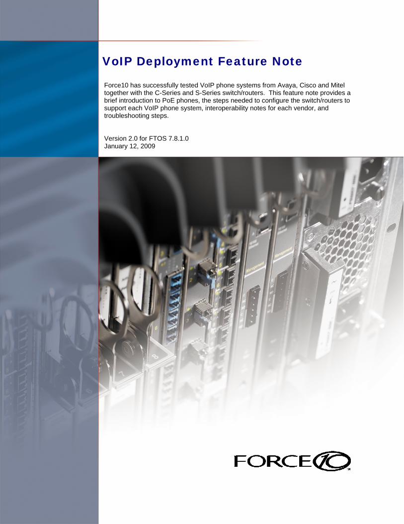
Device Software Version
Force10 FTOS FTOS 7.8.1.0
Avaya 4160SW and 4621SW Phones 2.8.3
Cisco 7961G-GE, V1 and V2 Phones SIP.8.3.3SR2
Mitel 5330 Phones 3300 MX Controller ICP Release 7.0.21.5
- 2 -
VoIP Deployment Feature Note
C300
Cisco CallManager
Linux Server (for Avaya)
Mitel Controller
- 3 -
VoIP Deployment Feature Note
Introduction VoIP phones on the market today follow the same basic boot and operations process:
1. Wait for an LLDP packet from the Ethernet switch 2. Send a DHCP discovery packet to find the DHCP server 3. Send a DHCP request to the DHCP server to get an IP address 4. Send an LLDP-MED packet to the Ethernet switch 5. Wait for an LLDP-MED packet from the Ethernet switch and read the Network Policy TLV to get the VLAN ID,
L2 Priority and DSCP value 6. Download applications and software from the call manager 7. After configuration, voice packets are sent as tagged frames and data packets are sent as untagged frames
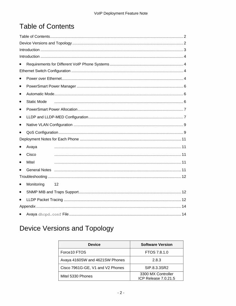
Requirements for Different VoIP Phone Systems Avaya phones require the Avaya Communication Manager appliance. This appliance was simulated for this configuration example by using a Linux server that was configured as the DHCP and file server for the phones. A VLAN was created and configured as tagged on the ports that connected the phones, and untagged on the port that connected the server. The Avaya application files for the phones were copied to the server and were sent to the phones after they booted. The dhcp.conf file was configured with specific attributes that the Avaya phones needed to operate and can be found in the Appendix. Cisco phones require an appliance running the Cisco Call Manager software, which includes a DHCP server. A VLAN was created and configured as tagged on the ports that connected the phones, and untagged on the port that connected the call manager. Mitel phones require the Mitel Controller and a DHCP server. A VLAN was created and configured as tagged on the ports that connected the phones, and untagged on the port that connected the call manager. Through this document, any references to “call manager” refer to the Avaya Communication Manager, the Cisco Call Manager, or the Mitel Controller.
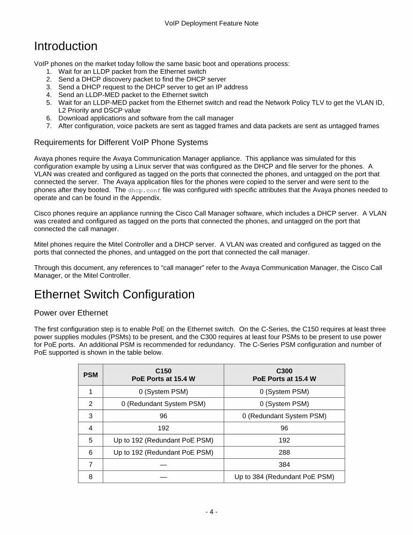
Ethernet Switch Configuration Power over Ethernet The first configuration step is to enable PoE on the Ethernet switch. On the C-Series, the C150 requires at least three power supplies modules (PSMs) to be present, and the C300 requires at least four PSMs to be present to use power for PoE ports. An additional PSM is recommended for redundancy. The C-Series PSM configuration and number of PoE supported is shown in the table below.
PSM C150 PoE Ports at 15.4 W
C300 PoE Ports at 15.4 W
1 0 (System PSM) 0 (System PSM)
2 0 (Redundant System PSM) 0 (System PSM)
3 96 0 (Redundant System PSM)
4 192 96
5 Up to 192 (Redundant PoE PSM) 192
6 Up to 192 (Redundant PoE PSM) 288
7 — 384
8 — Up to 384 (Redundant PoE PSM)
- 4 -
VoIP Deployment Feature Note
The S-Series S25V and S50V support PoE in both stand alone and stacking modes. The power supply built into the system provides 470 watts, which is allocated to system and PoE power. For applications that require more power for PoE or power redundancy, an external 470 watt power supply is available. The external power supply can operate in two modes:
• Load sharing: provides 470 W redundant power in case a power supply fails • Current sharing: provides 940 W total power when the current sharing terminal is connected (the power
stack-unit command is used to allocate PoE power) Power for PoE is allocated as follows on the S-Series:
• FTOS 7.7.1.0: 150 watts for system power and 320 watts for PoE power (20 ports @ 15.4 watts) • FTOS 7.8.1.0: S25V - 110 watts for system power and 360 watts for PoE power (~24 ports @ 15.4 watts)
S50V - 150 watts for system power and 320 watts for PoE power (20 ports @ 15.4 watts)
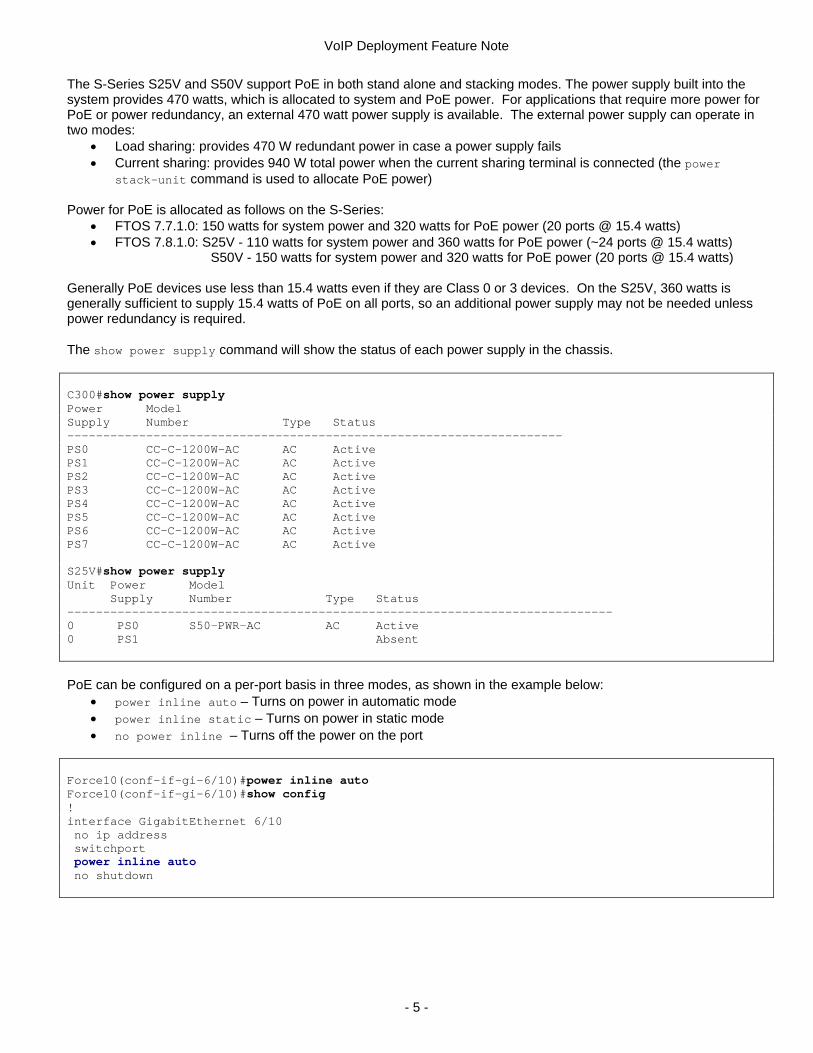
Generally PoE devices use less than 15.4 watts even if they are Class 0 or 3 devices. On the S25V, 360 watts is generally sufficient to supply 15.4 watts of PoE on all ports, so an additional power supply may not be needed unless power redundancy is required. The show power supply command will show the status of each power supply in the chassis. C300#show power supply Power Model Supply Number Type Status --------------------------------------------------------------------- PS0 CC-C-1200W-AC AC Active PS1 CC-C-1200W-AC AC Active PS2 CC-C-1200W-AC AC Active PS3 CC-C-1200W-AC AC Active PS4 CC-C-1200W-AC AC Active PS5 CC-C-1200W-AC AC Active PS6 CC-C-1200W-AC AC Active PS7 CC-C-1200W-AC AC Active S25V#show power supply Unit Power Model Supply Number Type Status ---------------------------------------------------------------------------- 0 PS0 S50-PWR-AC AC Active 0 PS1 Absent
PoE can be configured on a per-port basis in three modes, as shown in the example below:
• power inline auto – Turns on power in automatic mode • power inline static – Turns on power in static mode • no power inline – Turns off the power on the port
Force10(conf-if-gi-6/10)#power inline auto Force10(conf-if-gi-6/10)#show config ! interface GigabitEthernet 6/10 no ip address switchport power inline auto no shutdown
- 5 -
VoIP Deployment Feature Note
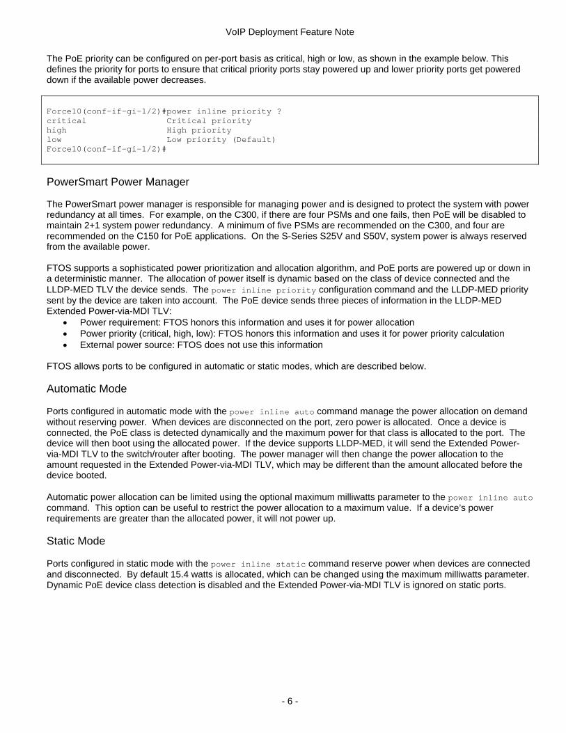
The PoE priority can be configured on per-port basis as critical, high or low, as shown in the example below. This defines the priority for ports to ensure that critical priority ports stay powered up and lower priority ports get powered down if the available power decreases. Force10(conf-if-gi-1/2)#power inline priority ? critical Critical priority high High priority low Low priority (Default) Force10(conf-if-gi-1/2)#
PowerSmart Power Manager
The PowerSmart power manager is responsible for managing power and is designed to protect the system with power redundancy at all times. For example, on the C300, if there are four PSMs and one fails, then PoE will be disabled to maintain 2+1 system power redundancy. A minimum of five PSMs are recommended on the C300, and four are recommended on the C150 for PoE applications. On the S-Series S25V and S50V, system power is always reserved from the available power. FTOS supports a sophisticated power prioritization and allocation algorithm, and PoE ports are powered up or down in a deterministic manner. The allocation of power itself is dynamic based on the class of device connected and the LLDP-MED TLV the device sends. The power inline priority configuration command and the LLDP-MED priority sent by the device are taken into account. The PoE device sends three pieces of information in the LLDP-MED Extended Power-via-MDI TLV:
• Power requirement: FTOS honors this information and uses it for power allocation • Power priority (critical, high, low): FTOS honors this information and uses it for power priority calculation • External power source: FTOS does not use this information
FTOS allows ports to be configured in automatic or static modes, which are described below. Automatic Mode
Ports configured in automatic mode with the power inline auto command manage the power allocation on demand without reserving power. When devices are disconnected on the port, zero power is allocated. Once a device is connected, the PoE class is detected dynamically and the maximum power for that class is allocated to the port. The device will then boot using the allocated power. If the device supports LLDP-MED, it will send the Extended Power-via-MDI TLV to the switch/router after booting. The power manager will then change the power allocation to the amount requested in the Extended Power-via-MDI TLV, which may be different than the amount allocated before the device booted. Automatic power allocation can be limited using the optional maximum milliwatts parameter to the power inline auto command. This option can be useful to restrict the power allocation to a maximum value. If a device’s power requirements are greater than the allocated power, it will not power up. Static Mode
Ports configured in static mode with the power inline static command reserve power when devices are connected and disconnected. By default 15.4 watts is allocated, which can be changed using the maximum milliwatts parameter. Dynamic PoE device class detection is disabled and the Extended Power-via-MDI TLV is ignored on static ports.
- 6 -
VoIP Deployment Feature Note
PowerSmart Power Allocation
PoE power allocation is dependent on the total inline power available to the system and the power priority calculation. The power priority calculation is based on the following four parameters:
1. Mode: automatic or static mode, static mode has higher priority than automatic mode 2. Configured priority (critical, high, low): the priority configured with the power inline priority command 3. LLDP-MED priority (critical, high, low): the priority sent by the device in the Extended Power-via-MDI TLV 4. Slot and port number: only used as a tie breaker, the lowest numbered port has the highest priority
PowerSmart updates the system and PoE power allocation when an event happens that requires the priorities to be evaluated:
• The port configuration changes • The device sends a different LLDP-MED priority • A device is connected or disconnected • A power supply is added or removed
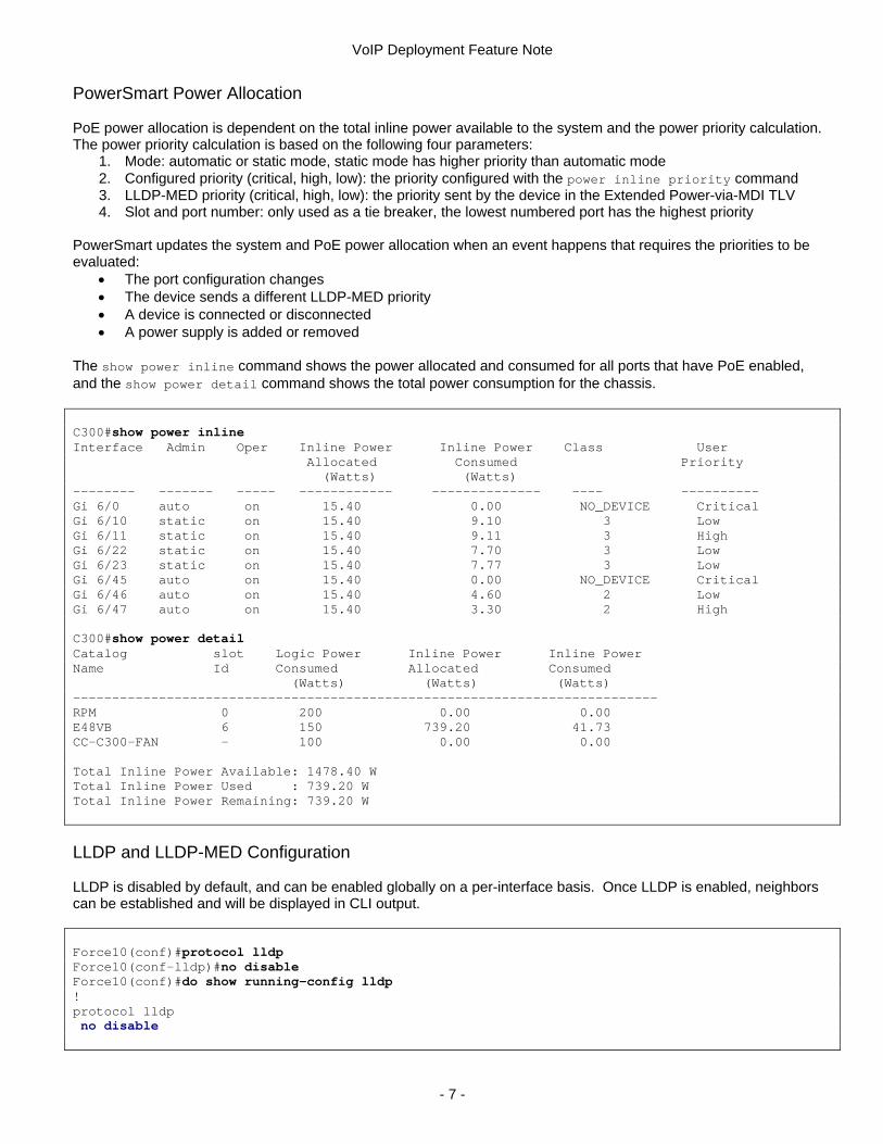
The show power inline command shows the power allocated and consumed for all ports that have PoE enabled, and the show power detail command shows the total power consumption for the chassis. C300#show power inline Interface Admin Oper Inline Power Inline Power Class User Allocated Consumed Priority (Watts) (Watts) -------- ------- ----- ------------ -------------- ---- ---------- Gi 6/0 auto on 15.40 0.00 NO_DEVICE Critical Gi 6/10 static on 15.40 9.10 3 Low Gi 6/11 static on 15.40 9.11 3 High Gi 6/22 static on 15.40 7.70 3 Low Gi 6/23 static on 15.40 7.77 3 Low Gi 6/45 auto on 15.40 0.00 NO_DEVICE Critical Gi 6/46 auto on 15.40 4.60 2 Low Gi 6/47 auto on 15.40 3.30 2 High C300#show power detail Catalog slot Logic Power Inline Power Inline Power Name Id Consumed Allocated Consumed (Watts) (Watts) (Watts) --------------------------------------------------------------------------- RPM 0 200 0.00 0.00 E48VB 6 150 739.20 41.73 CC-C300-FAN - 100 0.00 0.00 Total Inline Power Available: 1478.40 W Total Inline Power Used : 739.20 W Total Inline Power Remaining: 739.20 W
LLDP and LLDP-MED Configuration LLDP is disabled by default, and can be enabled globally on a per-interface basis. Once LLDP is enabled, neighbors can be established and will be displayed in CLI output. Force10(conf)#protocol lldp Force10(conf-lldp)#no disable Force10(conf)#do show running-config lldp ! protocol lldp no disable
- 7 -
VoIP Deployment Feature Note
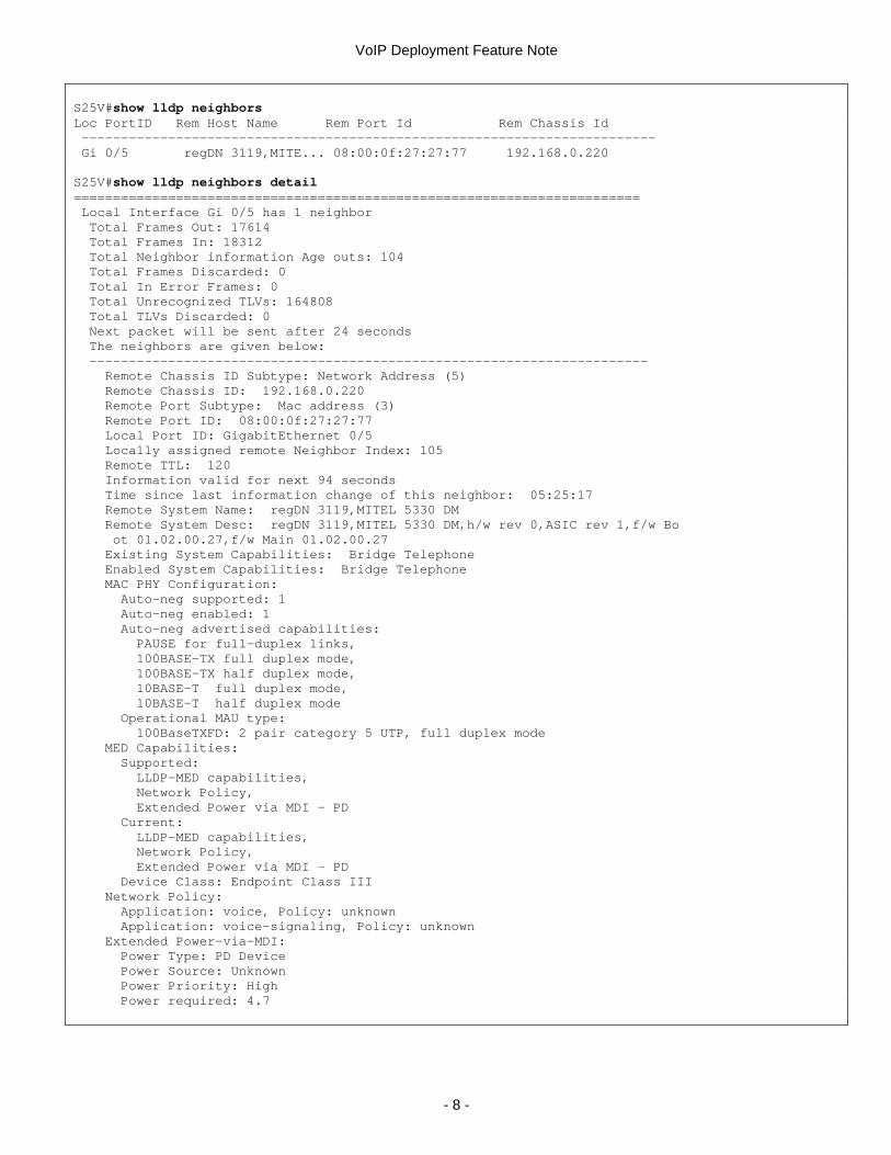
S25V#show lldp neighbors Loc PortID Rem Host Name Rem Port Id Rem Chassis Id ------------------------------------------------------------------------- Gi 0/5 regDN 3119,MITE... 08:00:0f:27:27:77 192.168.0.220 S25V#show lldp neighbors detail ======================================================================== Local Interface Gi 0/5 has 1 neighbor Total Frames Out: 17614 Total Frames In: 18312 Total Neighbor information Age outs: 104 Total Frames Discarded: 0 Total In Error Frames: 0 Total Unrecognized TLVs: 164808 Total TLVs Discarded: 0 Next packet will be sent after 24 seconds The neighbors are given below: ----------------------------------------------------------------------- Remote Chassis ID Subtype: Network Address (5) Remote Chassis ID: 192.168.0.220 Remote Port Subtype: Mac address (3) Remote Port ID: 08:00:0f:27:27:77 Local Port ID: GigabitEthernet 0/5 Locally assigned remote Neighbor Index: 105 Remote TTL: 120 Information valid for next 94 seconds Time since last information change of this neighbor: 05:25:17 Remote System Name: regDN 3119,MITEL 5330 DM Remote System Desc: regDN 3119,MITEL 5330 DM,h/w rev 0,ASIC rev 1,f/w Bo ot 01.02.00.27,f/w Main 01.02.00.27 Existing System Capabilities: Bridge Telephone Enabled System Capabilities: Bridge Telephone MAC PHY Configuration: Auto-neg supported: 1 Auto-neg enabled: 1 Auto-neg advertised capabilities: PAUSE for full-duplex links, 100BASE-TX full duplex mode, 100BASE-TX half duplex mode, 10BASE-T full duplex mode, 10BASE-T half duplex mode Operational MAU type: 100BaseTXFD: 2 pair category 5 UTP, full duplex mode MED Capabilities: Supported: LLDP-MED capabilities, Network Policy, Extended Power via MDI - PD Current: LLDP-MED capabilities, Network Policy, Extended Power via MDI - PD Device Class: Endpoint Class III Network Policy: Application: voice, Policy: unknown Application: voice-signaling, Policy: unknown Extended Power-via-MDI: Power Type: PD Device Power Source: Unknown Power Priority: High Power required: 4.7
- 8 -
VoIP Deployment Feature Note
FTOS only transmits LLDP-MED packets on a port after it has received one, to ensure that LLDP-MED packets are only exchanged with devices that support them. LLDP-MED must be enabled in the LLDP configuration as follows. Force10(conf)#protocol lldp Force10(conf-lldp)#advertise med Force10(conf-lldp)#show config ! protocol lldp advertise med no disable
Each IP phone vendor transmits their voice and data packets with a specific default 802.1p priority and DSCP value. These defaults can be changed through the LLDP-MED Network Policy configuration option. The phones can be provisioned with the following three attributes:
• VLAN • 802.1p priority • DSCP value
When the phone receives this TLV, it starts transmitting tagged packets with the specified VLAN, 802.1p priority and DSCP value. Of the three phones tested, only Mitel phones honor the configuration option. Cisco phones honor the VLAN and continue to use its own default 802.1p priority and DSCP value. Avaya phones ignore this option and have a proprietary way of learning the VLAN, which is discussed in the “Avaya Deployment Notes” section below. Most IP phones look for “voice” or “voice-signaling” application types in this option. Configure the VLAN, 802.1p priority and DSCP value that should be used by the phones. The VLAN must be the same VLAN that connects the call manager. Force10(conf-lldp)#advertise med voice 2000 5 55 Force10(conf-lldp)#advertise med voice-signaling 2000 5 55 Force10(conf-lldp)#show config ! protocol lldp advertise med advertise med voice 2000 5 55 advertise med voice-signaling 2000 5 55 no disable
Native VLAN Configuration Many phones require or can use a native VLAN mode which sends tagged and untagged Ethernet frames on the same physical port. Configure each port as portmode hybrid to enable native VLAN mode on the switch/router. QoS Configuration QoS policies can be configured in order to ensure that voice traffic gets higher priority over the data traffic in the network. Four steps are needed to create a QoS policy:
1. Classify the voice traffic using a class map 2. Associate the classified voice traffic with a hardware queue using a policy map 3. Apply the policy map on the ports that connect the phones 4. Configure strict priority queuing for the hardware (service) queue for voice traffic
Packets can be classified using 802.1p bits, DSCP values or an ACL. The following example uses DSCP values for classification. Voice traffic is sent with DSCP 20 and data traffic with DSCP 0. Voice traffic will be sent to service queue 1, which will be put into strict priority mode so that this queue always is serviced first.
- 9 -
VoIP Deployment Feature Note
! Create a class map based on the DSCP value. Force10(conf)#class-map match-all voice-dscp-cmap Force10(conf-class-map)#match ip dscp 20 Force10(conf-class-map)#show config ! class-map match-all voice-dscp-cmap match ip dscp 20 ! Create an input policy map using the class map and associate it with service queue 1. Force10(conf)#policy-map-input voice-policy-inp Force10(conf-policy-map-in)#service-queue 1 class-map voice-dscp-cmap Force10(conf-policy-map-in)#show config ! policy-map-input voice-policy-inp service-queue 1 class-map voice-dscp-cmap ! Apply the policy map on the ports that connect the phones. Force10(conf-if-gi-6/46)#service-policy input voice-policy-inp Force10(conf-if-gi-6/46)#show config ! interface GigabitEthernet 6/46 no ip address switchport service-policy input voice-policy-inp no shutdown ! Enable strict priority queuing with the highest priority for service queue 1. This is a global command. Force10(conf)#strict-priority unicast 1 Force10(conf)#do show running-config | grep strict strict-priority unicast 1
You can also use the trust diffserv option to queue based on received default DSCP values, as shown in the following example. The configuration guide lists the default DSCP to service queue mappings, which should be used to configure the corresponding service queue as strict priority. Force10#show running-config policy-map-input ! policy-map-input HonorDSCP trust diffserv Force10#show run interface gigabitethernet 6/11 ! interface GigabitEthernet 6/11 no ip address portmode hybrid switchport service-policy input HonorDSCP power inline auto no shutdown
- 10 -
VoIP Deployment Feature Note
If QoS classification should use the default 802.1p bits instead of DSCP values, use the command service-class dynamic dot1p on the ports that connect the phones. The configuration guide lists the default 802.1p bits to service queue mappings, which should be used to configure the corresponding service queue as strict priority. Force10#show running-config interface gi 6/10 ! interface GigabitEthernet 6/10 no ip address portmode hybrid switchport service-class dynamic dot1p power inline auto shutdown
Deployment Notes for Each Phone Avaya
Avaya software version 2.6 and higher support LLDP-MED, but the LLDP-MED Network Policy TLV is not supported yet. An unofficial software release is available that enables the Avaya phones to use the VLAN ID advertised with LLDP-MED. Details are in this thread on the Avaya website http://www.avayausers.com/showthread.php?t=7194. As a workaround you can use the VLAN Name TLV supported in FTOS 7.7.1.0 to provision the VLAN ID on the Avaya phones. The VLAN name must start with the word “voice” (case insensitive) as shown in this example. Force10(conf)#interface vlan 2 Force10(conf-if-vl-2)#name voiceNetwork Force10(conf-if-vl-2)#protocol lldp Force10(conf-lldp)#advertise dot1-tlv vlan-name vlan-id 2
Avaya phones use 802.1p priority 6 and DSCP value 46 for voice traffic. References: http://www.avaya.com/master-usa/en-us/resource/assets/applicationnotes/extreme-dot1x01.pdf Cisco When configured to use LLDP-MED, Cisco phones use the VLAN but ignore the QoS values that are sent in software version 8.3(3) or later. The phones use 802.1p priority 5 and DSCP value 46 for voice traffic. References: http://www.cisco.com/en/US/technologies/tk652/tk701/technologies_white_paper0900aecd804cd46d.html Mitel When configured to use LLDP-MED, Mitel phones send 802.1p priority 0 and DSCP value 0 initially and then use the VLAN and QoS values that are sent through LLDP-MED. General Notes • Phones pick up network policy changes via LLDP when they boot. If the network policy changes on the
switch/router, then the phones must be rebooted for the policy to take effect. • If the port that connects a phone is untagged, the phone can’t learn the VLAN and 802.1p priority. LLDP can be
configured to advertise the 802.1p priority using the command advertise med <app> priority-tagged.
- 11 -
VoIP Deployment Feature Note
Troubleshooting Monitoring If there is a speed or duplex mismatch, the following message will be logged: %RPM0-P:CP %LLDP-3-MAC_PHY_CFG: Configuration mismatch with neighbor on interface Gi 6/23 A power configuration mismatch may be logged because FTOS currently does not support power negotiation: %RPM0-P:CP %LLDP-3-EXT_POW_MDI: Configuration mismatch with neighbor on interface Gi 6/10 SNMP MIB and Traps Support The following MIBs are supported:
• LLDP MIB http://www.ieee802.org/1/files/public/MIBs/lldp.mib • LLDP-EXT-MED MIB http://www.tiaonline.org/standards/technology/voip/documents/ANSI-TIA-
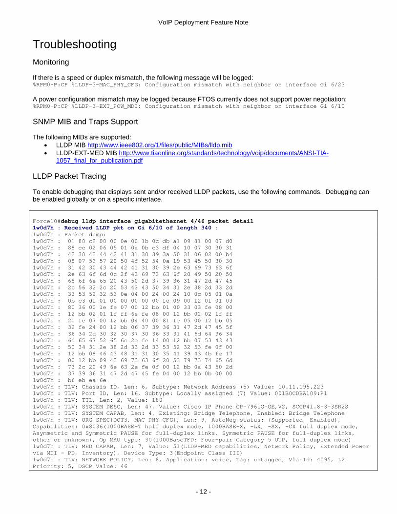
1057_final_for_publication.pdf LLDP Packet Tracing To enable debugging that displays sent and/or received LLDP packets, use the following commands. Debugging can be enabled globally or on a specific interface. Force10#debug lldp interface gigabitethernet 4/46 packet detail 1w0d7h : Received LLDP pkt on Gi 6/10 of length 340 : 1w0d7h : Packet dump: 1w0d7h : 01 80 c2 00 00 0e 00 1b 0c db a1 09 81 00 07 d0 1w0d7h : 88 cc 02 06 05 01 0a 0b c3 df 04 10 07 30 30 31 1w0d7h : 42 30 43 44 42 41 31 30 39 3a 50 31 06 02 00 b4 1w0d7h : 08 07 53 57 20 50 4f 52 54 0a 19 53 45 50 30 30 1w0d7h : 31 42 30 43 44 42 41 31 30 39 2e 63 69 73 63 6f 1w0d7h : 2e 63 6f 6d 0c 2f 43 69 73 63 6f 20 49 50 20 50 1w0d7h : 68 6f 6e 65 20 43 50 2d 37 39 36 31 47 2d 47 45 1w0d7h : 2c 56 32 2c 20 53 43 43 50 34 31 2e 38 2d 33 2d 1w0d7h : 33 53 52 32 53 0e 04 00 24 00 24 10 0c 05 01 0a 1w0d7h : 0b c3 df 01 00 00 00 00 00 fe 09 00 12 0f 01 03 1w0d7h : 80 36 00 1e fe 07 00 12 bb 01 00 33 03 fe 08 00 1w0d7h : 12 bb 02 01 1f ff 6e fe 08 00 12 bb 02 02 1f ff 1w0d7h : 20 fe 07 00 12 bb 04 40 00 81 fe 05 00 12 bb 05 1w0d7h : 32 fe 24 00 12 bb 06 37 39 36 31 47 2d 47 45 5f 1w0d7h : 36 34 2d 30 32 30 37 30 36 33 31 41 6d 64 36 34 1w0d7h : 6d 65 67 52 65 6c 2e fe 14 00 12 bb 07 53 43 43 1w0d7h : 50 34 31 2e 38 2d 33 2d 33 53 52 32 53 fe 0f 00 1w0d7h : 12 bb 08 46 43 48 31 31 30 35 41 39 43 4b fe 17 1w0d7h : 00 12 bb 09 43 69 73 63 6f 20 53 79 73 74 65 6d 1w0d7h : 73 2c 20 49 6e 63 2e fe 0f 00 12 bb 0a 43 50 2d 1w0d7h : 37 39 36 31 47 2d 47 45 fe 04 00 12 bb 0b 00 00 1w0d7h : b6 eb ea 6e 1w0d7h : TLV: Chassis ID, Len: 6, Subtype: Network Address (5) Value: 10.11.195.223 1w0d7h : TLV: Port ID, Len: 16, Subtype: Locally assigned (7) Value: 001B0CDBA109:P1 1w0d7h : TLV: TTL, Len: 2, Value: 180 1w0d7h : TLV: SYSTEM DESC, Len: 47, Value: Cisco IP Phone CP-7961G-GE,V2, SCCP41.8-3-3SR2S 1w0d7h : TLV: SYSTEM CAPAB, Len: 4, Existing: Bridge Telephone, Enabled: Bridge Telephone 1w0d7h : TLV: ORG_SPEC[DOT3, MAC_PHY_CFG], Len: 9, AutoNeg status: (Supported, Enabled), Capabilities: 0x8036(1000BASE-T half duplex mode, 1000BASE-X, -LX, -SX, -CX full duplex mode, Asymmetric and Symmetric PAUSE for full-duplex links, Symmetric PAUSE for full-duplex links, other or unknown), Op MAU type: 30(1000BaseTFD: Four-pair Category 5 UTP, full duplex mode) 1w0d7h : TLV: MED CAPAB, Len: 7, Value: 51(LLDP-MED capabilities, Network Policy, Extended Power via MDI - PD, Inventory), Device Type: 3(Endpoint Class III) 1w0d7h : TLV: NETWORK POLICY, Len: 8, Application: voice, Tag: untagged, VlanId: 4095, L2 Priority: 5, DSCP Value: 46
- 12 -
VoIP Deployment Feature Note
1w0d7h : TLV: NETWORK POLICY, Len: 8, Application: voice-signaling, Tag: untagged, VlanId: 4095, L2 Priority: 4, DSCP Value: 32 1w0d7h : TLV: EXT POWER, Len: 7, Power type: PD Device, Source: Unknown, Priority: Unknown, Power required: 12.9 Watts 1w0d7h : TLV: ENDOFPDU, Len: 0 1w0d7h : Forming LLDP pkt to send out of interface Gi 6/10 1w0d7h : TLV: Chassis ID, Len: 7, Subtype: Mac address (4), Value: 00:01:e8:48:e6:94 1w0d7h : TLV: Port ID, Len: 21, Subtype: Interface name (5), Value: GigabitEthernet 6/10 1w0d7h : TLV: TTL, Len: 2, Value: 120 1w0d7h : TLV: ORG_SPEC [DOT3, MAC_PHY_CFG] , Len: 9, AutoNeg status: (Supported, Enabled), Ad Capab: 0x6c03(1000BASE-T full duplex mode, 1000BASE-T half duplex mode, 100BASE-TX full duplex mode, 100BASE-TX half duplex mode, 10BASE-T full duplex mode, 10BASE-T half duplex mode), Op MAU type: 30(1000BaseTFD: Four-pair Category 5 UTP, full duplex mode) 1w0d7h : TLV: MED CAPAB, Len: 7, Capabilities: LLDP-MED capabilities, Network Policy, Location Identification, Extended Power via MDI - PSE, Device Type: Network Connectivity 1w0d7h : TLV: NETWORK POLICY, Len: 8, Value: App:voice, Tag:untagged, L2 Priority:5, DSCP Value:55 1w0d7h : TLV: NETWORK POLICY, Len: 8, Value: App:voice-signaling, Tag:untagged, L2 Priority:5, DSCP Value:55 1w0d7h : TLV: ENDOFPDU, Len: 0 1w0d7h : Sending LLDP pkt out of Gi 6/10 of length 96 1w0d7h : Packet dump: 1w0d7h : 01 80 c2 00 00 0e 00 01 e8 48 eb 21 81 00 00 00 1w0d7h : 88 cc 02 07 04 00 01 e8 48 e6 94 04 15 05 47 69 1w0d7h : 67 61 62 69 74 45 74 68 65 72 6e 65 74 20 36 2f 1w0d7h : 31 30 06 02 00 78 fe 09 00 12 0f 01 03 6c 03 00 1w0d7h : 1e fe 07 00 12 bb 01 00 0f 04 fe 08 00 12 bb 02 1w0d7h : 01 00 01 77 fe 08 00 12 bb 02 02 00 01 77 00 00 1w0d7h : 1w0d7h : LLDP frame sent out successfully of Gi 6/10
- 13 -
VoIP Deployment Feature Note
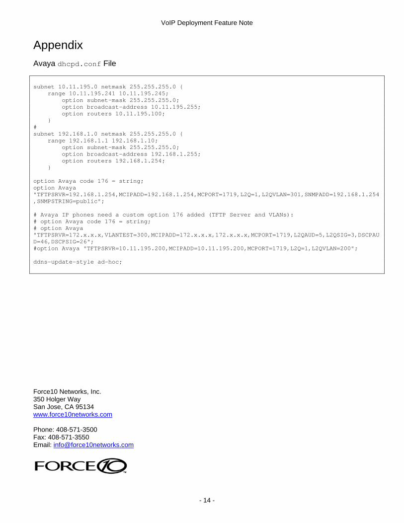
Appendix Avaya dhcpd.conf File subnet 10.11.195.0 netmask 255.255.255.0 { range 10.11.195.241 10.11.195.245; option subnet-mask 255.255.255.0; option broadcast-address 10.11.195.255; option routers 10.11.195.100; } # subnet 192.168.1.0 netmask 255.255.255.0 { range 192.168.1.1 192.168.1.10; option subnet-mask 255.255.255.0; option broadcast-address 192.168.1.255; option routers 192.168.1.254; } option Avaya code 176 = string; option Avaya "TFTPSRVR=192.168.1.254,MCIPADD=192.168.1.254,MCPORT=1719,L2Q=1,L2QVLAN=301,SNMPADD=192.168.1.254,SNMPSTRING=public"; # Avaya IP phones need a custom option 176 added (TFTP Server and VLANs): # option Avaya code 176 = string; # option Avaya "TFTPSRVR=172.x.x.x,VLANTEST=300,MCIPADD=172.x.x.x,172.x.x.x,MCPORT=1719,L2QAUD=5,L2QSIG=3,DSCPAUD=46,DSCPSIG=26"; #option Avaya "TFTPSRVR=10.11.195.200,MCIPADD=10.11.195.200,MCPORT=1719,L2Q=1,L2QVLAN=200"; ddns-update-style ad-hoc; Force10 Networks, Inc. 350 Holger Way San Jose, CA 95134 www.force10networks.com Phone: 408-571-3500 Fax: 408-571-3550 Email: [email protected]
- 14 -