Embed Size (px)
Citation preview

ISSN: 2319-8753
International Journal of Innovative Research in Science,
Engineering and Technology
(ISO 3297: 2007 Certified Organization)
Vol. 2, Issue 8, August 2013
Copyright to IJIRSET www.ijirset.com 3701
DESIGN AND ANALYSIS OF KINETIC
ENERGY RECOVERY SYSTEM IN
BICYCLES Sreevalsan S Menon
1, Sooraj M S
2, Sanjay Mohan
3, Rino Disney
4, Suneeth Sukumaran
5
Final year student, Department of Mechanical Engineering, JyothiEngineering & College,
Cheruthuruthy, Thrissur, India1,2,3,4
Assistant Professor, Department of Mechanical Engineering, JyothiEngineering & College,
Cheruthuruthy, Thrissur, India5
Abstract: Kinetic Energy Recovery System (KERS) is a system for recovering the moving vehicle's kinetic energy
under braking and also to convert the usual loss in kinetic energy into gain in kinetic energy.When riding a bicycle, a
great amount of kinetic energy is lost while braking, making start up fairly strenuous. Here we used mechanical kinetic
energy recovery system by means of a flywheel to store the energy which is normally lost during braking, and reuse it
to help propel the rider when starting. The rider can charge the flywheel when slowing or descending a hill and boost
the bike when accelerating or climbing a hill. The flywheel increases maximum acceleration and nets 10% pedal energy
savings during a ride where speeds are between 12.5 and 15 mph.
Keywords: KERS, Regenerative braking, Flywheel energy storage, Flywheel bicycle, Mechanical KERS, Smart
braking
I. INTRODUCTION
KERS is a collection of parts which takes some of the kinetic energy of a vehicle under deceleration, stores this energy
and then releases this stored energy back into the drive train of the vehicle, providing a power boost to that vehicle. For
the driver, it is like having two power sources at his disposal, one of the power sources is the engine while the other is
the stored kinetic energy. Kinetic energy recovery systems (KERS) store energy when the vehicle is braking and return
it when accelerating. During braking, energy is wasted because kinetic energy is mostly converted into heat energy or
sometimes sound energy that is dissipated into the environment. Vehicles with KERS are able to harness some of this
kinetic energy and in doing so will assist in braking. By a proper mechanism, this stored energy is converted back into
kinetic energy giving the vehicle extra boost of power.There are two basic types of KERS systems i.e. Electrical and
Mechanical. The main difference between them is in the way they convert the energy and how that energy is stored
within the vehicle. Battery-based electric KERS systems require a number of energy conversions each with
corresponding efficiency losses. On reapplication of the energy to the driveline, the global energy conversion efficiency
is 31–34%. The mechanical KERS system storing energy mechanically in a rotating fly wheel eliminates the various
energy conversions and provides a global energy conversion efficiency exceeding 70%, more than twice the efficiency
of an electric system.
This design of KERS bicycle was motivated by a desire to build a flywheel energy storage unit as a proof of concept.
On a flat road, the cyclist can maintain a fixed cruising speed to get from point to point. Globally all roads are flat with
impediments such as intersections, cars, and turns that force the cyclist to reduce speed, then accelerate.

ISSN: 2319-8753
International Journal of Innovative Research in Science,
Engineering and Technology
(ISO 3297: 2007 Certified Organization)
Vol. 2, Issue 8, August 2013
Copyright to IJIRSET www.ijirset.com 3702
Fig.1 Flywheel KERS Bicycle
A flywheel can temporarily store the kinetic energy from the bicycle when the rider needs to slow down. The energy
stored in the flywheel can be used to bring the cyclist back up to cruising speed. In this way the cyclist recovers the
energy normally lost during braking. In addition to increased energy efficiency, the flywheel-equipped bicycle is more
fun to ride since the rider has the ability to boost speed.The flywheel bicycle model is shown in figure 1.
II. KERS BICYCLE WORKING
A crank wheel connected to the rear wheels always rotates the clutch plate, connected in the flywheel axle. This is
being achieved by using chain transmission at a specified gear ratio, crank to clutch sprocket helps us to increase the
overall speed of flywheel. Now at a time when a speed reduction is required, clutch is applied which makes the contact
between the clutch and flywheel. Then the flywheel starts rotating, also the speed of bicycle is decreased. Thus a
regenerative braking system is achieved. On course energy is stored in flywheel. In case the brake has to be applied
fully then after flywheel rotations clutch is disengaged and the brake is applied. Now when we again rides the bicycle
during which we would apply clutches at this time as rear wheel rotation is lesser compared to flywheel the energy gets
transmitted from the flywheel to the wheels. Now also we can reduce the overall pedalling power required in course of
overrides by having clutch fully engaged. We can reduce overall pedalling power by 10 per cent. Also situation arises
such as traffic jam, down climbing a hill where we do not intend to apply brake fully. For such cases we can apply our
smart braking system which would allow us to decelerate and allow us to boost acceleration after this during normal
riding and distance that can be covered by pedalling can also improve.
During normal rides situations may arise we need to reduce the speed without braking fully such as traffic jams taking
turns etc. we can store the energy that would normally be wasted due to speed reduction by the application of clutch.
When the clutch is engaged that time due to initial engage the flywheel rotation consumes energy which would result in
speed reduction thus a braking effect. After some instances the energy is being stored in the flywheel this can be
reused by the engage of clutch plate and energy transfer from the flywheel occurs whenever the rotation is high enough
to rotate rear wheel. Thus if sudden braking then applied we can disengage the flywheel connections so that flywheel
energy is not wasted and going to take ride the speed of rear wheel is null and hence engage would help in returning the
energy from the flywheel to rear wheel. While riding downhill we always use braking for allowing slowdown. This is
the best case where we can store maximum amount of energy in our flywheel. The flywheel can be engaged for full
downhill ride and after all for some distance we need not ride the bicycle which would be done by the flywheel. This is
the main advantage area of KERS bicycle. During long drive the engage can be made full time. This will help in
reducing the overall pedalling effort. It has been found that the pedalling power can be reduced by 10 per cent during
long drives. Also this would help in avoiding pedalling effort at some points of ride. The complete KERS bicycle is
shown in figure 2 below.

ISSN: 2319-8753
International Journal of Innovative Research in Science,
Engineering and Technology
(ISO 3297: 2007 Certified Organization)
Vol. 2, Issue 8, August 2013
Copyright to IJIRSET www.ijirset.com 3703
Fig. 2 KERS Bicycle
III. DESIGN REQUIREMENTS
There are many requirements that need to be met to produce a product that is both feasible and optimal. There are also
some constraints, both geometric and engineering that also need to be satisfied. The following list describes these
requirements and constraints:
Store energy while braking
This is the main requirement and the overall objective of the device and must be suitable to meet the rider‟s
needs.
Return energy to start up
Once the energy is stored in the device, it is necessary to have a simple way to release this energy back to the
user in positive way. This can be accomplished with an innovative chain drive system.
Must fit on a bicycle
This is one of the most difficult constraints to achieve and most important because we are dealing with such
confined spacing. The objective is to fit the flywheel and accessories in the bicycle.
Light weight
The importance of having a light weight design is driven by the rider‟s desire to have a bicycle that is more
manoeuvrable and more portable. This is also a direct trade off with how much energy can be stored in the
flywheel.
Good stopping range
The stopping range is important because this product needs to be usable in real life situations. This component
can be optimized to have the shortest stopping distance using dynamic analysis.
Good stopping force
The force required to stop is dependent on the stopping range and the comfort levels of the rider. It is also
related to the possible flywheel features.
Inexpensive and affordable
This product must be able to make a profit and be desirable.
Safe to user and environmentally friendly
Safety is always a very important aspect whenever there is a consumer product.
Economical
The product economical and the products for this design must be cheaply available.
Reliable

ISSN: 2319-8753
International Journal of Innovative Research in Science,
Engineering and Technology
(ISO 3297: 2007 Certified Organization)
Vol. 2, Issue 8, August 2013
Copyright to IJIRSET www.ijirset.com 3704
It is important to have a product that is reliable and this requirement will affect the normal bicycling process
and must be easy to use.
Manufacturability
In order to make anything economical, it needs to be manufacturability, hence the important of having a
product that can be made easily and cheaply.
Aesthetically pleasing
This is not a requirement that needs to be taken heavily, but the design should always have nice look about it,
because looks will persuade the rider.
Modular
Having a device that can be adapted to existing bicycles is essential to be added to the existing ones so that it‟s
easier to adopt. This also can reduce other types of manufacturing costs.
Should not hinder normal riding
To have a successful accessory for a bicycle, the ride should not feel a noticeable change in the riding
performance or in the normal riding motion. A device that impedes the normal riding experience would be
considered undesirable.
Controlled release
The energy that is released back to the user must be done in a safe and manageable fashion. This can be a
consideration after the prototype is completed.
IV. FABRICATION PROCESS
A. Frame Modification
The frame modification is the first part of the fabrication that has to be done. The frame has to be modified by adding
steel tube. One end has to be welded at the handle end and the other at the rear wheel centre. The frame should have
enough strength so as to carry the flywheel and the additional forces that comes to play. The modification should not
hinder normal riding. Also the modified frame should have enough space in order to accommodate flywheel and clutch
assemblies. This is shown in figure 3 below.
Fig. 3 Frame Modified
ISSN: 2319-8753
International Journal of Innovative Research in Science,
Engineering and Technology
(ISO 3297: 2007 Certified Organization)
Vol. 2, Issue 8, August 2013
Copyright to IJIRSET www.ijirset.com 3705
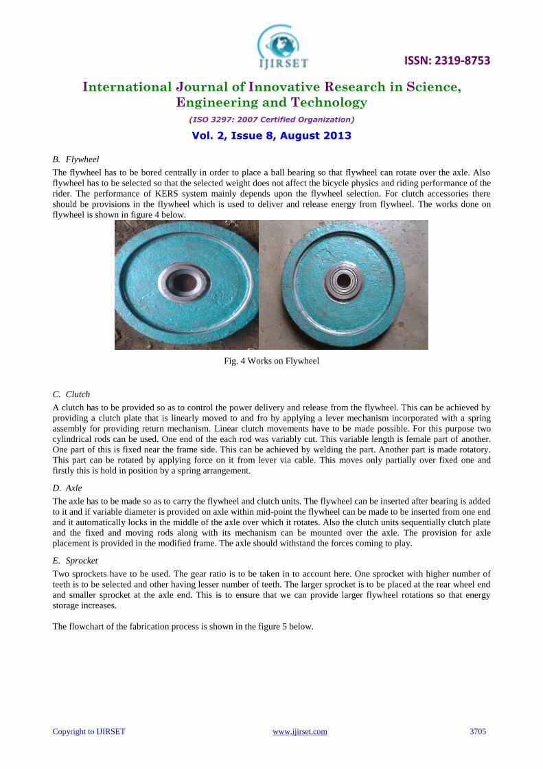
B. Flywheel
The flywheel has to be bored centrally in order to place a ball bearing so that flywheel can rotate over the axle. Also
flywheel has to be selected so that the selected weight does not affect the bicycle physics and riding performance of the
rider. The performance of KERS system mainly depends upon the flywheel selection. For clutch accessories there
should be provisions in the flywheel which is used to deliver and release energy from flywheel. The works done on
flywheel is shown in figure 4 below.
Fig. 4 Works on Flywheel
C. Clutch
A clutch has to be provided so as to control the power delivery and release from the flywheel. This can be achieved by
providing a clutch plate that is linearly moved to and fro by applying a lever mechanism incorporated with a spring
assembly for providing return mechanism. Linear clutch movements have to be made possible. For this purpose two
cylindrical rods can be used. One end of the each rod was variably cut. This variable length is female part of another.
One part of this is fixed near the frame side. This can be achieved by welding the part. Another part is made rotatory.
This part can be rotated by applying force on it from lever via cable. This moves only partially over fixed one and
firstly this is hold in position by a spring arrangement.
D. Axle
The axle has to be made so as to carry the flywheel and clutch units. The flywheel can be inserted after bearing is added
to it and if variable diameter is provided on axle within mid-point the flywheel can be made to be inserted from one end
and it automatically locks in the middle of the axle over which it rotates. Also the clutch units sequentially clutch plate
and the fixed and moving rods along with its mechanism can be mounted over the axle. The provision for axle
placement is provided in the modified frame. The axle should withstand the forces coming to play.
E. Sprocket
Two sprockets have to be used. The gear ratio is to be taken in to account here. One sprocket with higher number of
teeth is to be selected and other having lesser number of teeth. The larger sprocket is to be placed at the rear wheel end
and smaller sprocket at the axle end. This is to ensure that we can provide larger flywheel rotations so that energy
storage increases.
The flowchart of the fabrication process is shown in the figure 5 below.

ISSN: 2319-8753
International Journal of Innovative Research in Science,
Engineering and Technology
(ISO 3297: 2007 Certified Organization)
Vol. 2, Issue 8, August 2013
Copyright to IJIRSET www.ijirset.com 3706
Fig. 5 Fabrication flowchart
V. RESULT AND ANALYSIS
The flywheel bicycle increases efficiency on rides where the rider slows often. The additional weight is outweighed by
the ability to recover energy normally lost during braking. Thus the addition of extra weight does not make it difficult
for the rider. Also clutch provided helps in deciding the time period of activity. The overall result is that KERS system
is efficient in storing the energy normally lost in braking and returns it for boosting.
A. Weight And Performance
Normally energy stored in the flywheel is directly proportional to the weight and radius. Hence increase in weight
proves to improve the performance. But as we know that the maximum safe weight that can be used is limited due to
frame properties and rider compatibility. And also after some extent the radius can‟t be increased and the energy
storage thus seems to be limited to some particular extend. This is also because of the fact that the total running speed
is being reduced due to weight. Energy storage capacity increases with increase in weight but limitation seems to be the
speed driving the flywheel. And performance of system is directly linked with the energy stored. Thus a graph can be
plotted between performance and weight. Optimum value lies between 5 and 8 kg.
Energy stored in flywheel, Ek= 1
2𝐼ω2
Where, „I‟ is the moment of inertia
„ω‟ is the rotational velocity (rpm)
Moment of inertia, I = 𝑘𝑚𝑟2
Where, „k‟ is inertial constant (depends on shape)
„m‟ is mass of the disc
„r‟ is the radius
Thus Ek is directly proportional to the mass of the disc
The flywheel and transmission add weight to the bicycle. The increased weight will add to the energy required to
accelerate the bicycle and to ride it uphill. However, once the rider has provided the energy to reach a cruising speed,
the flywheel reduces the energy cost of slowing down from this speed since it aids in subsequent acceleration. Roads
are optimal environment for the flywheel bicycle because it‟s flat and there are lots of reasons for the cyclist to slow

ISSN: 2319-8753
International Journal of Innovative Research in Science,
Engineering and Technology
(ISO 3297: 2007 Certified Organization)
Vol. 2, Issue 8, August 2013
Copyright to IJIRSET www.ijirset.com 3707
down. The performance versus weight graph is shown in figure 6 and the comparison of weight of ordinary and
flywheel bicycle is shown in figure 7 below.
Fig.6 Performance Versus Weightfig. 7 Weight Comparison Between Flywheel Bicycle And
Conventional Bicycle
B. Comparison Analysis
Comparison is made between conventional bicycle and the KERS bicycle. The major things looked up was velocity,
kinetic energy and pedal power input. The velocities of both seemed to be similar but the distance covered by flywheel
is somewhat greater. A graph velocity versus time between both bicycles can be plotted. Next is the kinetic energy
taken in to account. The flywheel has an extra kinetic energy that is being stored and hence from conventional bicycle
flywheel bicycle is having an additional kinetic energy of flywheel. Graph connecting kinetic energy and time can be
plotted. Now pedal power is taken to account. The flywheel bicycle has additional acceleration that is being boosted up
by the flywheel acceleration. Hence conventional bicycle pedalling power can be achieved by less effort in case of
flywheel bicycle. A graph can for pedal power input versus time.
A side-by-side comparison, shown in figure, of the flywheel bicycle and a conventional bicycle during a ride cycle
illustrates how the flywheel bicycle saves energy. Once at cruising speed the riders of both bikes reduce speed
temporarily and return to the cruising speed three times before coming to a stop. This frequent deceleration and
acceleration is typical of a rider riding through red lights where he/she must slow for crossing traffic. During
deceleration, the rider on the conventional bicycle applies the brakes to reduce speed, while the rider on the flywheel
bicycle shifts the transmission to charge the flywheel. In both deceleration stages, the kinetic energy of the bike is
reduced, but on the flywheel bike, the energy is transferred to the flywheel. The pedal power input is plotted for both
riders. Both input pedal power to overcome the same drag force, shown in blue. In order to return to cruising speed,
the rider on the conventional bike needs to input pedal power to accelerate, shown in green. However the rider on the
flywheel bike can transfer energy from the flywheel back to the bike by shifting the transmission to boost the bike. The

ISSN: 2319-8753
International Journal of Innovative Research in Science,
Engineering and Technology
(ISO 3297: 2007 Certified Organization)
Vol. 2, Issue 8, August 2013
Copyright to IJIRSET www.ijirset.com 3708
rider of the flywheel bike doesn‟t need pedal power to accelerate! The sum of the drag and acceleration power is
shown in grey. The area of this sum of pedal power input is the total pedal energy input since energy is the integral of
power over time. Hence, the rider on the flywheel bicycle uses less energy than the rider on the conventional bike. This
is depicted in figure 8 below.
Fig. 8 Ride Cycle comparison between flywheel bicycle and conventional bicycle
C. Overdrive Test
This test was carried out to find out how much pedalling power can be saved by having KERS bicycle. This was done
by riding the bicycle on a slope and initial pedalling was given same and noted down the distance at which the bicycle
stops when flywheel is not being connected. Then taken 10 m back point from the stopping distance. The experiment
was again done by riding cycle with flywheel coupled from 10 m side and noted down the extra distance that was
covered by the bicycle. The result was tabulated. The values reveal a total gain in energy of about nearly 10 per cent.
Thus flywheel bicycles can help in reducing the overall pedalling power by 10 per cent used in overdrives.

ISSN: 2319-8753
International Journal of Innovative Research in Science,
Engineering and Technology
(ISO 3297: 2007 Certified Organization)
Vol. 2, Issue 8, August 2013
Copyright to IJIRSET www.ijirset.com 3709
TABLE I OVERDRIVE TEST
Number of trials
Distance Covered
Flywheel Engaged Flywheel disengaged
1 10 metres 10.60 metres
2 10 metres 10.76 metres
3 10 metres 10.72 metres
4 10 metres 10.86 metres
VI. CONCLUSION
KERS system used in the vehicles satisfies the purpose of saving a part of the energy lost during braking. Also it can be
operated at high temperature range and are efficient as compared to conventional braking system. The results from
some of the test conducted show that around 30% of the energy delivered can be recovered by the system. KERS
system has a wide scope for further development and the energy savings. The use of more efficient systems could lead
to huge savings in the economy of any country. Here we are concluding that the topic KERS got a wide scope in
engineering field to minimize the energy loss. As now a day‟s energy conservation is very necessary thing. Here we
implemented KERS system in a bicycle with an engaging and disengaging clutch mechanism for gaining much more
efficiency. As many mating parts is present large amount of friction loss is found in this system which can be improved.
Boost is reduced because of friction. Continuously variable transmission can be implemented to this system which
would prove in drastic improvement in energy transmissions.
REFERENCES
[1] Siddharth K. Patil., “Regenerative Braking System in Automobiles”, International Journal of Research in Mechanical Engineering
&Technology vol.2, pp.45-46,2012. [2] Chibulka.J.,“Kinetic Energy Recovery System by means of Flywheel Energy Storage”, Advanced Engineering Vol. 3,No. 1, pp. 27-38,1998.
[3] S.J.Clegg, “A Review of Regenerative Braking System”, Institute of Transport Studies, University of Leeds, Working paper of 471, 1996.
[4] SaharatChanthanumataporn, SarawutLerspalungsanti and MonsakPimsarn, “Design of Regenerative Braking System for an electric vehicle modified from used car”, Second TSME International Conference on Mechanical Engineering, 19-21 Oct,2011.
[5] Dr. IqbalHusain, “Electric and hybrid Vehicles: DesignFundamentals”, CRC press, Taylor and Francis Group, USA,2012.
[6] Gao, Y., Chen , L., Ehsani, M.,“Investigation of theEffectiveness of Regenerative Braking for EV and HEV”,SAE Paper 1999-01-2910,1999.
[7] John M. Miller , “Propulsion Systems for Hybrid Vehicles”, Institute of Electrical Engineers, UK,2004.
[8] Chen, J-X , Jiang, J-Z. Wang, X-J.,“Research of Energy Regeneration Technology in Electric Vehicle”, Shanghai University Press, Vol. 7, No
2, pp.25-36,2008. [9] Papalambros, P.Y., and D.J. Wilde , “Principles of Optimal Design”, 2nd Ed. Cambridge University Press, New Your, NY,2010.