Embed Size (px)
Citation preview

ISSN (Print) : 2320 – 3765
ISSN (Online): 2278 – 8875
International Journal of Advanced Research in Electrical,
Electronics and Instrumentation Engineering
(An ISO 3297: 2007 Certified Organization)
Vol. 3, Issue 8, August 2014
10.15662/ijareeie.2014.0308022 Copyright to IJAREEIE www.ijareeie.com 11131
A Parametric Analysis of Magnetic Braking –
The Eddy Current Brakes – For High Speed
and Power Automobiles and Locomotives
Using SIMULINK
Er. Shivanshu Shrivastava
B.Tech, Department of Electrical & Electronics Engineering, VIT University, Vellore, India
ABSTRACT: Eddy Current braking technique is a classical example of how effective and efficient braking be obtained
from application of magnetic field. Eddy current braking is based on the principle of relative motion between a
magnetic source and a metal. In this paper, eddy current braking system is modeled in SIMULINK and effects of
various parameters are observed over the overall braking. This would provide a comparative study between the various
parameters involved and understand the braking system.
I.INTRODUCTION
Braking forms an important part of motion of any automobile or locomotive. Effective braking ensures the safety of the
passengers and goods an automobile or a locomotive is carrying. Hence, new and effective braking techniques are
required which increase the efficiency of the existing braking system by either replacing the older systems or by
providing an auxiliary support whenever required. The main advantage of eddy current brakes lies over the fact that,
more the relative motion between the metal and the magnetic source, more would be the braking force observed by the
metal disc. Owing to their efficiency at very high speeds these brakes are used in high speed locomotives and their
scope can be further increased to high performance/racing automobiles. Another important advantage is that it has no
loses due to friction and thus improves the overall efficiency of the system. Thus, it is important to understand the
various parameters that affect the braking force.
II.BACKGROUND
Current is induced when a conductor is introduced in a variable magnetic flux. This can be achieved by either exerting
a time varying magnetic field over a static conductor or a static magnetic field over a moving conductor. In Eddy
current braking system, a conducting disc is rotated in the air gap of the magnetic field produced by a permanent
magnet or an electromagnet. Using electromagnets is a much efficient method since; the setup can be activated as per
requirement. When the disc rotates in the magnetic field, eddy currents are induced into the conductor in such a manner
that they oppose the cause producing it. As a result of the interaction between the magnetic field produced by the
induced eddy currents and the magnetic field of the electromagnet, a braking force is experienced which causes braking
or retardation of the disc. This braking force is dependent upon the velocity of rotating disc. The braking force
increases as the velocity of disc increases.
When the metal plate enters the magnetic field, a Lorentz force,
F = q (𝒗 × 𝑩 )
The force experienced by the electron in the disc causes induced current which in such a way that it opposes the cause
producing it. Thus, induced current flows in closed paths. Certain papers [2] mention about the proposed models and
the equations regarding the eddy current braking. They propose W.R. Smythe‟s Model, D.Schieber‟s Model and J.H.
Wouterse‟s Model.

ISSN (Print) : 2320 – 3765
ISSN (Online): 2278 – 8875
International Journal of Advanced Research in Electrical,
Electronics and Instrumentation Engineering
(An ISO 3297: 2007 Certified Organization)
Vol. 3, Issue 8, August 2014
10.15662/ijareeie.2014.0308022 Copyright to IJAREEIE www.ijareeie.com 11132
The former two propose valid results at low speeds whereas the third model is acceptable at high speed ranges also. It
states that at low speed:
𝐹𝑒 =1
4
𝜋
𝜌𝐷2𝑑𝐵0
2𝑐𝑣
𝑐 =1
2= 1 −
1
4
1
1 +𝑟1𝐴
2
𝐴 − 𝑟1
𝐷
2
At high speeds the braking force is :
𝑣𝑘 =2
𝜇°
1
𝑐𝜀 𝜌
𝑑
𝑥
𝐷
𝐹𝑒 =
1
𝜇°
𝑐
𝜀 𝜋
4 𝐷2𝐵0
2 𝑥
𝐷
𝐹𝑒 = 𝐹𝑒
2𝑣𝑘
𝑣+
𝑣𝑣𝑘
The list of various symbols used is given in table 1:
Table 1 : List of Symbols
Symbol Meaning and Measurement
𝝆 Specific resistance of disc material
𝜺 Ratio of zone width to air gap
𝒗𝒌 Critical Speed i.e., Speed at which
exerted force is maximum
𝑩𝟎 Strength of Magnetic Field
𝒅 Thickness of disc (m)
D Diameter of Soft Iron pole (m)
𝒄 Proportionality factor, ratio of total
disc resistance to resistance of part
under pole
𝒗 Tangential Speed of Rotating disc
𝒙 Air gap between the poles
r1 Distance of centre of pole from centre
of disc
A Total radius of disc
III.OBSERVATIONS
The SIMULINK model is modeled using the above mentioned equation of "𝐹𝑒" at both high speed and low speed. In
order to determine the dependency of the braking torque, 𝐹𝑒 , over a particular parameter, that parameter is varied as a
Ramp signal keeping the other parameters constant. Through this we generate a time varying signal of the parameter
under consideration. For example, if the dependency of braking torque over velocity of disc is to be established then the
velocity of disc is fed as a Ramp signal varying with time of positive slope. Results can be obtained with any time

ISSN (Print) : 2320 – 3765
ISSN (Online): 2278 – 8875
International Journal of Advanced Research in Electrical,
Electronics and Instrumentation Engineering
(An ISO 3297: 2007 Certified Organization)
Vol. 3, Issue 8, August 2014
10.15662/ijareeie.2014.0308022 Copyright to IJAREEIE www.ijareeie.com 11133
varying signal of any slope, the author chooses time varying ramp signals. The basic SIMULINK model would look as
following :
Figure 1 :SIMULINK Model
Effect of change in velocity, 𝒗:
In Fig 2, The speed is varied from 0-250 m/s i.e., 0-900km/hr. The following graph is obtained with Velocity on Y-
axis and time on X-axis. A ramp Signal with slope 5 is used to provide velocity varying with time. The highest speed
being 250m/s.
Figure 2 : Velocity increasing with time
Figure 3: Braking Force at Low Speeds Figure 4: Braking Force at High Speeds

ISSN (Print) : 2320 – 3765
ISSN (Online): 2278 – 8875
International Journal of Advanced Research in Electrical,
Electronics and Instrumentation Engineering
(An ISO 3297: 2007 Certified Organization)
Vol. 3, Issue 8, August 2014
10.15662/ijareeie.2014.0308022 Copyright to IJAREEIE www.ijareeie.com 11134
In Fig 3, It can be clearly observed that, as the speed increases the braking torque (on Y-axis) also increases. At High
Speed i.e., greater than 100 m/s the modeling is carried out according to the equation of braking force at high speeds. In
Fig. 4, As observed, it can be concluded that the braking torque increases as velocity increases and hence, the braking
torque stops acting when the velocity of the disc equals to zero. The reason of the trends observed in the above to graph
is because, as stated by Lorentz law, mentioned above, as the relative velocity increases the magnitude of eddy current
induced in disc increases which causes, and thus the induced eddy currents would try to oppose the cause producing it
and hence higher value of braking torque is obtained. braking torque is directly proportional to the relative velocity of
the source to the rotating metal. As the relative velocity between then increases, more braking force would be
generated. This particular reason aids Eddy current brakes to be used in at High Speed applications as the high
magnitude of braking force can be generated.
Effect of change in Magnetic Field, 𝑩𝟎:
In fig 4, the Magnetic field is increased from 0-2T, then its effect on the braking torque can be observed in Figure 5 and
figure 6 for low speeds and high speeds respectively. The trend observed in both Fig 5 and Fig 6, indicates that the
observed braking force increases as the magnitude of Magnetic Field increases. Since, the braking force increases, thus
the brakes would work more over the wheel to stop its rotation and reduce its speed efficiently and much faster than the
conventional braking system. The reason for the trends obtained in Fig 5 and Fig 6 can also be explained by Lorentz
law. Since, eddy currents induced also depend upon the magnetic field of the source producing it. As the magnetic field
increases so will the eddy currents induced and hence, the increased magnitude of eddy currents would oppose the
cause producing it. The interaction of the two magnetic fields of the source and that produced by induced eddy current
would generate the braking torque in a value proportional to the change in magnetic field. Thus, increase in magnetic
field causes increase in braking force.
Figure 4 : Increasing Magnetic field Figure 5 : Braking Force at low Speed
Figure 6 : Braking Force at High Speed - Increases as Magnetic Field increases
ISSN (Print) : 2320 – 3765
ISSN (Online): 2278 – 8875
International Journal of Advanced Research in Electrical,
Electronics and Instrumentation Engineering
(An ISO 3297: 2007 Certified Organization)
Vol. 3, Issue 8, August 2014
10.15662/ijareeie.2014.0308022 Copyright to IJAREEIE www.ijareeie.com 11135
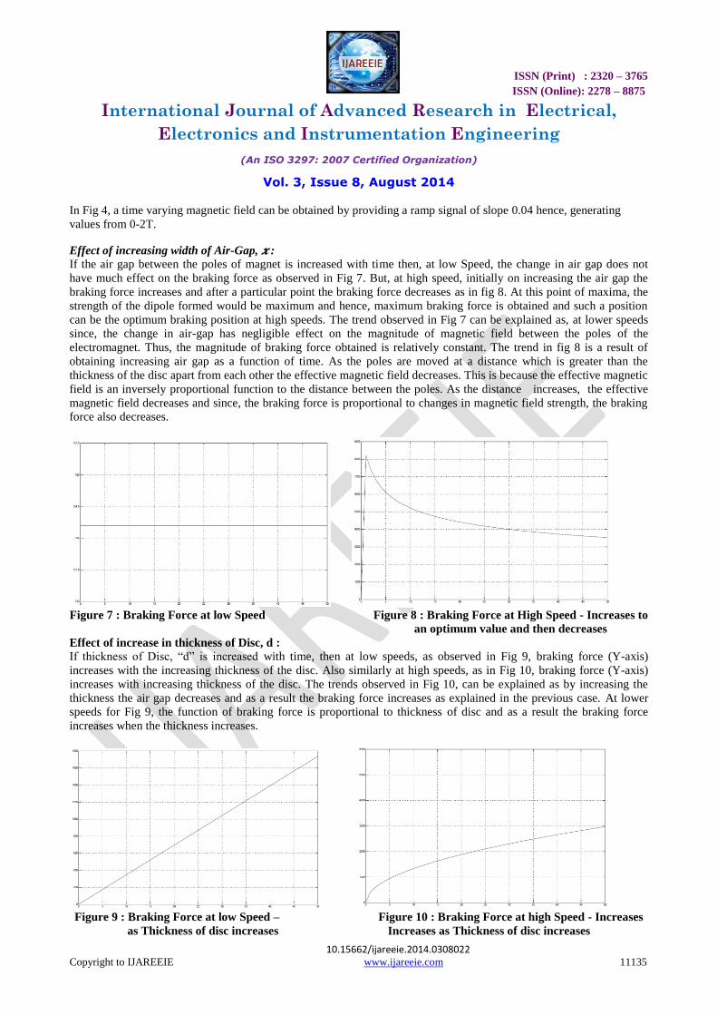
In Fig 4, a time varying magnetic field can be obtained by providing a ramp signal of slope 0.04 hence, generating
values from 0-2T.
Effect of increasing width of Air-Gap, 𝒙 : If the air gap between the poles of magnet is increased with time then, at low Speed, the change in air gap does not
have much effect on the braking force as observed in Fig 7. But, at high speed, initially on increasing the air gap the
braking force increases and after a particular point the braking force decreases as in fig 8. At this point of maxima, the
strength of the dipole formed would be maximum and hence, maximum braking force is obtained and such a position
can be the optimum braking position at high speeds. The trend observed in Fig 7 can be explained as, at lower speeds
since, the change in air-gap has negligible effect on the magnitude of magnetic field between the poles of the
electromagnet. Thus, the magnitude of braking force obtained is relatively constant. The trend in fig 8 is a result of
obtaining increasing air gap as a function of time. As the poles are moved at a distance which is greater than the
thickness of the disc apart from each other the effective magnetic field decreases. This is because the effective magnetic
field is an inversely proportional function to the distance between the poles. As the distance increases, the effective
magnetic field decreases and since, the braking force is proportional to changes in magnetic field strength, the braking
force also decreases.
Figure 7 : Braking Force at low Speed Figure 8 : Braking Force at High Speed - Increases to
an optimum value and then decreases
Effect of increase in thickness of Disc, d :
If thickness of Disc, “d” is increased with time, then at low speeds, as observed in Fig 9, braking force (Y-axis)
increases with the increasing thickness of the disc. Also similarly at high speeds, as in Fig 10, braking force (Y-axis)
increases with increasing thickness of the disc. The trends observed in Fig 10, can be explained as by increasing the
thickness the air gap decreases and as a result the braking force increases as explained in the previous case. At lower
speeds for Fig 9, the function of braking force is proportional to thickness of disc and as a result the braking force
increases when the thickness increases.
Figure 9 : Braking Force at low Speed – Figure 10 : Braking Force at high Speed - Increases
as Thickness of disc increases Increases as Thickness of disc increases

ISSN (Print) : 2320 – 3765
ISSN (Online): 2278 – 8875
International Journal of Advanced Research in Electrical,
Electronics and Instrumentation Engineering
(An ISO 3297: 2007 Certified Organization)
Vol. 3, Issue 8, August 2014
10.15662/ijareeie.2014.0308022 Copyright to IJAREEIE www.ijareeie.com 11136
Effect of increase in position of centre of pole from centre of disc, r1:
Centre of pole refers to the distance of point where, line joining the centers of both the poles and the surface of the disc
meet, measured along the surface of the disc. As observed in fig 11 and fig 12, If this distance is increased, then the
braking force would decrease. This is because as we move away from the centre the effect of magnetic field produced
by the eddy current does not provide the same braking force as it did closer to the centre. This is because the effective
field at any point producing the eddy current depends inversely over r1. As r1 increases magnitude of effective
magnetic field decreases and thus braking force decreases. Braking force would be maximum at the centre and least at
the edges.
Figure 11 : Braking Force at low speeds – Figure 12 : Braking Force at high speeds - Decreases
asdistance from centre to pole increases Decreases as distance from centre to pole increases
Effect of increase in Diameter of pole which increases the area of magnetism over the disc, D :
If the diameter of soft iron pole is increased or the diameter of the area at which the magnetic source acts is increased
then the braking force also increases as can be observed from both fig 13 and fig 14. This is because as the diameter of
pole is increased the effective area where the eddy currents are produced increases. This causes an increase in
magnitude of the eddy currents, which produce magnetic field in the direction opposite to the cause producing the eddy
current. As the area is increased, magnitude of eddy current produced would increase and thus, increasing the force in
direction opposite to that of the source producing the eddy currents would be produced.
Figure 13 : Braking Force at low speeds – Figure 14 : Braking force at high speeds : Increases
as effective area increases Increases as effective area increases
IV. ADVANTAGES AND DISADVATAGES
Advantages:
Eddy current brakes depend upon the velocity the disc. Braking Force is more for higher velocity and reduces as
velocity is reduced and stops acting if the disc stops rotating. Also, Frictional loses are greatly reduced since, it has no
moving or sliding parts. This even reduces cost of maintenance. It can be used in addition to the existing brake system
as an auxiliary brakes to provide efficient braking at very high speeds.

ISSN (Print) : 2320 – 3765
ISSN (Online): 2278 – 8875
International Journal of Advanced Research in Electrical,
Electronics and Instrumentation Engineering
(An ISO 3297: 2007 Certified Organization)
Vol. 3, Issue 8, August 2014
10.15662/ijareeie.2014.0308022 Copyright to IJAREEIE www.ijareeie.com 11137
Disadvantages :
Since, it is dependent upon velocity of the disc hence, it cannot hold the disc at rest, as opposed to the holding force
provided by the static friction of conventional brakes. Also, the braking force decreases as the speed decreases and
hence, conventional brakes are required if more braking force is required. Maybe costly if operated for low speed
applications.
VI. PERFORMANCE EFFECTS ON AN EXISTING SYSTEM
Based on the observations above, it can be observed that if the above mentioned parameters are changed their effects
would be observed over the existing system with which they are working upon. If the magnitude of magnetic field is
increased or decreased then the braking force would increase or decrease respectively causing much faster and efficient
braking. Also the distance between the pole plays a major role at high speeds. The poles should be at a distance of the
optimum braking point, because of which the most efficient braking is obtained. Also, thickness of the disc, and
positioning of the poles play another important role. Altering any of the factor would alter the performance of the
brakes and hence, alter its efficiency. Also all parameters should parameters should be designed in such a way that
braking force doesn‟t reach a point where jerks are observed while braking and sliding of disc is not observed. The
applications include being used in High speed trains and high performance lifts. Hence, all the parameters needs to be
designed keeping the above observed trends in consideration. Also, eddy current braking system can act as a very
efficient braking system at high speeds and thus, be used as auxiliary brakes for many high speed applications along
with the conventional mechanical brakes being used. Since, both the brakes would act on the wheel or the shaft
responsible for braking, the effective time where the brakes act can be reduced and hence, the automobile or
locomotive be stopped in a much lesser time and distance.
V. CONCLUSION
Thus, the eddy current brakes are modeled and the various factors and parameters affecting the efficient braking are
observed. The above analysis could be reviewed while designing of eddy current brakes.
REFERENCES
[1] Manuel I Gonz´alez, “Experiments with Eddy Currents: the Eddy Brakes”, Institute of Physics Publishing, Vol. 25 , pp 463-468, 2004. [2] Der-Ming Ma, Jaw- Kuen Shiau, “The design of Eddy-current Magnet Brakes”, Transactions of Canadian Society for Mechanical Engineering,
Vol 35, pp 19-37, 2011.
[3] Jure Hribar, “Magnetic Braking”, Journal of mathematics and physics - University of Ljubljana, Vol 5, pp 26-39- 2008 [4] Marshall S V and Skitek G G, “Electromagnetic Concepts and Applications” 3rd edition (Englewood Cliffs, NJ: Prentice-Hall) pp 298–9,1990.
[5] El-Hawary, “Electrical Energy Systems”, Boca Raton, FL: CRC Press, pp 36–40, 2000
[6] Gagarin, G., Kroger, U. And Saunweber, E., „„Eddy-current magnetic track brakes for high speed trains,‟‟ Joint ASME/IEEE/AAR Railroad Conference, pp. 95–99, 1987
[7] Mcconnell, H.M., „„Eddy-current phenomena in ferromagnetic material,‟‟ AIEE Transactions, Vol. 73, part I, pp. 226–234, July, 1954.
[8] Sears F W, Zemansky M W, Young H D and Freedman R A “ F´ısica Universitaria, Novena Edici”, vol 2 (Mexico: Addison-Wesley), pp 957–8,1999
[9] Thomas D. Rossing and John R. Hull, “Magnetic Levitation”, Vol 2, The Physics Teacher, 552-561,1991.
[10] Tipler P, “Physics for Scientists and Engineers” 4th edn (New York: Freeman),pp 938–9,1999. [11] Serway R and Beichner R “Physics for Scientists and Engineers with Modern Pysics”, 5th edn (Fort Worth:Saunders) pp 997–9, 2000
[12] http://inventors.about.com/library/inventors/blrailroad3.html
[13] Electric Pulse magnetic Braking using Mechatronics [14] Iniguez J, Raposo V, Hernandez-Lopez A, Flores A G and Zazo M, “Study of the conductivity of a metallic tube by analysing the damped fall
of a magnet” Eur. J. Phys., Vol25, pp-593–604, 2004
[15] Levin Y, da Silveira F L and Rizzato F B, “Electromagnetic braking: a simple quantitative model”, Am. Journal of Phys. Vol 74, pp 815–7, 2006